


Measure what you see.
wave-scan dual wave-scan II
Operating Instructions
Betriebsanleitung
Mode de’emploi
A member of |
Additives & Instruments |
wave-scan dual
wave-scan II
Operating Instructions
Bedienungsanleitung
Mode d’emploi
|
|
|
|
|
|
|
|
|
|
|
|
|
|
|
|
|
|
Patent pending |
|
265 018 367 EDF 0709 |
|||
Patent angemeldet |
|
|
|
||
Demande de brevet en cours |
|
|
|
||
BYK-GardnerGmbH |
BYK-GardnerUSA |
||||
LausitzerStr.8 |
9104 Guilford Road |
||||
D-82538Geretsried |
Columbia, MD 21046 |
||||
Germany |
|
|
USA |
|
|
Tel. |
0-800-gardner |
Phone |
800-343-7721 |
|
|
|
(0-800-4273637) |
|
301-483-6500 |
|
|
|
+49-8171-3493-0 |
Fax |
800-394-8215 |
|
|
Fax |
+49-8171-3493-140 |
|
301-483-6555 |
|
|
www.byk.com/instruments
 Français Deutsch English
1

English
This instruction manual is an important part of this instrument. It contains essential information about setting up, placing in service and use. If you pass the device on to another user, please ensure that the instruction manual is included with the instrument. The manual must be studied carefully before working with the equipment. Please contact your regional service office if you have any questions or require additional information about the device.
The technology and fittings are based on state-of-the art optic and electronic technology. New developments and innovations are constantly being integrated into the equipment. Thus, the diagrams, dimensions, and technical data used in this manual may have changed as a result of adapting the device to new information and improvements.
© Copyright 2005 BYK-Gardner GmbH All rights reserved
No portion of the software, documentation or other accompanying materials may be translated, modified, reproduced, copied or otherwise duplicated (with the exception of a backup copy), or distributed to a third party, without prior written authorization from BYK-Gardner GmbH. In any case, this requires the prior written consent of BYK-Gardner.
BYK-Gardner GmbH offers no guarantee that the software will function without error or that the functions incorporated therein can be executed in all applications and combinations selected by you.
No liability other than as provided by law is assumed for direct or indirect damage sustained in association with the use of the instrument, the software or documentation.
BYK-Gardner GmbH reserves the right to update the software and written documentation without prior notice.
2
|
|
Table of contents |
|
|
|
|
|
|
|
|
English |
|
|
|
|
|
|
|
Contents/Inhalt |
|
|
||
|
|
|
|
||
|
|
|
Page/Seite |
|
|
|
English |
|
2 |
|
|
|
Deutsch |
62 |
|
|
|
|
Français |
122 |
|
|
|
|
|
|
|
|
|
|
|
|
Page |
|
|
1 |
Safety instructions |
4 |
|
|
|
2 |
Handling |
7 |
|
|
|
3 |
Commissioning and power supply |
8 |
|
|
|
4 |
System description |
11 |
|
|
|
5 |
Control elements |
14 |
|
|
|
6 |
Getting started |
16 |
|
|
|
7 |
Menu operation |
19 |
|
|
|
8 |
Overview of main menu |
21 |
|
|
|
9 |
Measure |
22 |
|
|
|
|
9.1 |
MEMORY |
25 |
|
|
|
9.2 |
Organizer |
26 |
|
|
|
9.3 |
Memory with Parameter input |
28 |
|
|
10 |
Configuration |
30 |
|
|
|
11 |
Advanced Configuration |
36 |
|
|
|
12 |
Memory |
38 |
|
|
|
13 |
Setup |
|
45 |
|
|
14 |
Testing the Instrument |
47 |
|
|
|
15 |
Installation of software |
49 |
|
|
|
16 |
Interface |
50 |
|
|
|
17 |
Technical data |
52 |
|
|
|
18 |
Delivery notes |
54 |
|
|
|
19 |
Infoand Error messages |
55 |
|
|
|
20 |
Cleaning and Maintenance |
60 |
|
|
|
21 |
EC Declaration of conformity |
182 |
|
|
|
3
English
1 |
Safety instructions |
|
|
|
|
No claims of product liability or warranty can be honored if the device is not operated in accordance with the operating instructions and the instructions on the instrument.
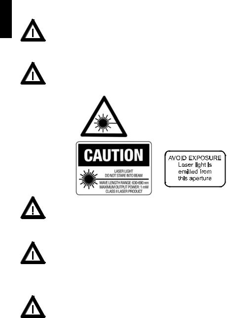
The measurement unit is a class II laser product.
The labels shown below are on the housing and base of the measurement unit.
|
|
|
|
Great Britain |
|
Laser Light |
|
|
|
Do not stare into beam |
|
|
|
Class 2 Laser Product |
|
|
|
max < 1 mW 630 – 690 nm |
|
|
|
According to IEC 825 |
|
|
|
|
|
|
|
|
|
|
|
(EN 60825) |
|
USA |
|
|
|
Caution:
Since the laser beam used for sampling can penetrate your eye and cause injuries, never dismantle the instrument and never look directly into the measurement aperture when the device is turned on.
• If you use the unit and accessories properly, there are no hazards to fear – none of a mechanical nature and none caused by electrical shock.
The following paragraphs contain information about the safe use of the device.
• Please use only original accessories provided by the manufacturer. Only the included external power supply may be used to power the docking station. See “Delivery Notes” and the “Technical Data” for further information.
4

Safety instructions |
1 |
|
|
• Avoid exposure to continuous humidity and condensation (see |
|
|
English |
Technical Data). Avoid splashing with water, chemicals or other liquids. |
|
|
|
|
|
|
|
• Never attempt to make any repairs to the instrument, neither |
|
|
|
|
|
|
|
mechanical nor electrical. Please consult our Technical Customer |
|
|
|
Service. |
|
|
|
• Only devices that meet the requirements for low-voltage safety |
|
|
|
may be connected to the USB interface. |
|
|
|
• For operation with the external power supply, care should be |
|
|
|
taken to ensure the nominal voltage of the power supply unit (see |
|
|
|
the manufacturer’s plate on the power supply unit) matches the |
|
|
|
voltage supplied by the power outlet. |
|
|
|
• The measurement device and accessories may be disconnected |
|
|
|
from the power supply as follows: |
|
|
|
Instrument: |
|
|
|
a)by removing the battery compartment or
b)by removing the rechargeable battery pack or
c)by removing the measurement unit from the docking station
Docking station:
a)by disconnecting the plug from the power supply unit on the docking station
b)by disconnecting the power supply unit plug from the socket
The power supply unit can be disconnect from the power supply by disconnecting the power connection line plug from the socket. Make certain that the power supply unit plug is easily accessible. Use only the power supply connection line included with delivery.
• When working with the batteries and the rechargeable battery pack, make certain there is no short circuit on the contacts. Metallic objects must not come in contact with the bare contacts.
5

1 |
Safety instructions |
|
English |
• Safety advices for batteries and rechargeable batteries: Do not |
|
crush or dismantle, do not heat or incinerate, do not immerse in any |
||
|
||
|
liquid. This may cause explosion or release harmful substances. |
|
|
• Rechargeable Li-Ion battery packs: Do not charge at temperatures |
|
|
below 0°C. The allowable discharge temperature range is -20 to |
|
|
+60°C. Please refer to the charging instructions in section „Power |
|
|
Supply“. |
|
|
• Caution: Batteries and rechargeable batteries are special waste |
|
|
and must not be disposed of with household trash. Make certain to |
|
|
observe the disposal instructions of the battery or rechargeable |
|
|
battery manufacturer. |
|
|
• You will find the technical data for all system components such as |
|
|
the measurement unit, battery compartment, rechargeable battery |
|
|
pack, docking station and power supply unit on the respective |
|
|
manufacturer’s plates and in the section Technical Data |
|
|
• Defects and extraordinary loads |
If safe operation can no longer be presumed, shut down the device and secure it against unintended operation.
The device must be presumed unsafe to operate:
•if visible damage is evident
•if the instrument is no longer working
•if it has been stored for long periods under adverse conditions
•after harsh treatment during shipping.
•This symbol means: Do not dispose of this product together with your household waste. Please refer to the information of your local community or contact our dealers regarding the proper handling of end-of life electric and electronic equipment.
Recycling of this product will help to conserve natural resources and prevent potential negetive consequences for the environment and human health caused by inappropriate waste handling
6
Handling |
2 |
|
|
• The measurement unit contains sensitive precision optical and electronic |
|
|
English |
parts. Do not drop it and protect it from being bumped or jostled! |
|
|
|
|
|
|
|
• Do not hold the unit by the measurement aperture or allow any foreign |
|
|
|
|
|
|
|
objects to get into this opening. |
|
|
|
• Do not expose the unit to direct sunlight for extended periods of time. Do |
|
|
|
not store it in a hot or dusty environment. The case that comes with the unit |
|
|
|
offers the best protection when the unit is being stored. |
|
|
|
• Avoid prolonged exposure to high relative humidity and do not allow water |
|
|
|
to form from condensation (see Technical Data). |
|
|
|
• Protect the measuring unit from moisture, chemicals and corrosive vapors. |
|
|
|
• Remove the batteries from the battery compartment when the device will go unused for an extended period of time. This will prevent potential damage to the unit.
• The display may go blank if the device is exposed to excessive static electricity. If this happens, wait until the instrument turns itself off automatically and then turn it on again.
• When the device is not in use, place it in the docking station. It is protected there and the rechargeable batteries included with delivery will be recharged.
7
3
English
Commissioning and power supply
Rechargeable battery pack
Battery compartment
Before operating the instrument for the first time, please read the operating manual and take particular notice of the Safety Instructions. Unpack the instrument and check the delivery for completeness (See chapter “Delivery Notes”).
Powering the instrument
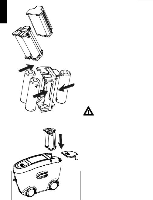
The measurement unit can be operated either with rechargeable battery pack included with delivery or with AA (LR6) alkaline batteries.
Battery:
To operate the instrument using batteries, the battery compartment must be fitted with three 1.5-V mignon AA(LR6) batteries and must be inserted into the measurement unit until it locks into place.
Ensure that the batteries are correctly oriented in the
compartment according to the (+) and (-) marks. See adjacent figure.
Use only alkaline batteries (AA /LR6)!
Depending on the specific brand, the capacity of the battery included with delivery is sufficient for about 1000 measurements. When the battery voltage falls below the required operating voltage in the course of operation, the following message appears on the display:
“Low Battery!”
To ensure that the instrument is always ready for operation, it is recommended to have the battery
8
Commissioning and power supply |
3 |
compartment and spare batteries handy, especially when performing measurements in the field.
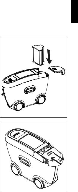
Rechargeable battery pack:
To place the instrument in service, the rechargeable battery pack must be inserted until it locks in place.
The rechargeable battery pack can only be attached when it is in the correct position.
When inserting the rechargeable battery pack, ensure that its contacts are aligned with those of the instrument. See adjacent figure.
The capacity of the rechargeable battery pack included with delivery is sufficient for about 1000 measurements. When the voltage of the rechargeable battery pack falls below the required operating voltage in the course of operation, the following message appears on the display: “Low Battery!”
Docking station power supply:
Power is supplied to the docking station through the external power supply unit. Connect the external power supply unit to the docking station. Connect the appropriate end of the power connection line to the power supply unit and the plug end of the power connection line to the power outlet after verifying that the specifications of the power supply unit match the power source in terms of current and voltage.
Note:To ensure uniform utilization, the rechargeble battery packs should be exchanged regularly between instrument and docking station (weekly recommended).
9 |
English
3 |
Commissioning and power supply |
English |
Charging the rechargeable battery |
||
The rechargeable battery pack |
|||
|
|||
|
included with delivery may be charged |
||
|
in the docking station. Charging time |
||
|
for an empty battery pack is aprox. 2 |
||
|
hours. Please note chapter “Safety |
||
|
Instructions”! |
||
|
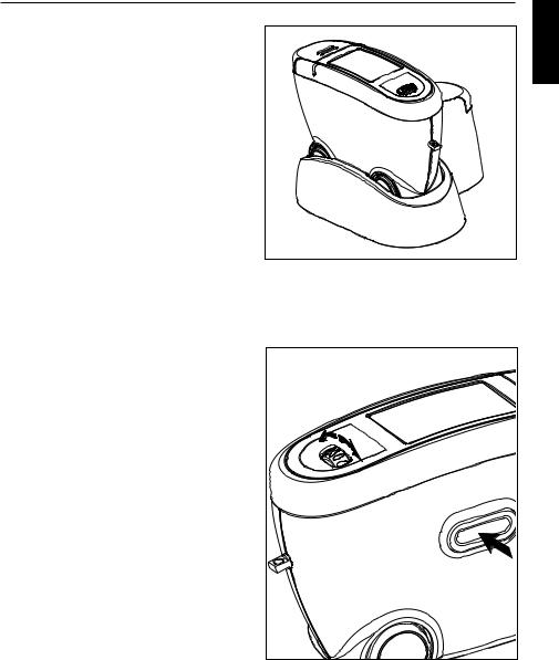
1. Battery pack in the instrument: |
||
|
The lithium ion rechargeable battery |
||
|
will begin charging immediately upon |
||
|
insertion of the instrument into the |
||
|
docking station. To do this, power |
||
|
must be supplied to the docking |
||
|
station through the corresponding po- |
||
|
wer supply unit. |
||
|
Insert the measurement unit into the |
||
|
docking station as shown in the |
||
|
neighboring illustration. |
||
|
2. Battery pack on docking station: |
||
|
A second charging shaft is located |
||
|
behind the shaft for the instrument. In- |
||
|
sert the second battery pack here for |
||
|
charging, so it will be handy at any |
||
|
time to replace the other battery when |
||
|
it is discharged. |
||
|
|
The compartment for AA |
|
|
|
batteries may not be inserted |
|
1 |
into the charging shaft. |
||
2 |
|
||
|
Charging indicator for: |
||
|
1: additional battery pack |
||
|
2: instrument |
||
|
Indication light: |
||
|
green: ready |
||
|
red: |
charging |
|
10

System description |
4 |
Please read the instruction manual before using the instrument and note the safety instructions.
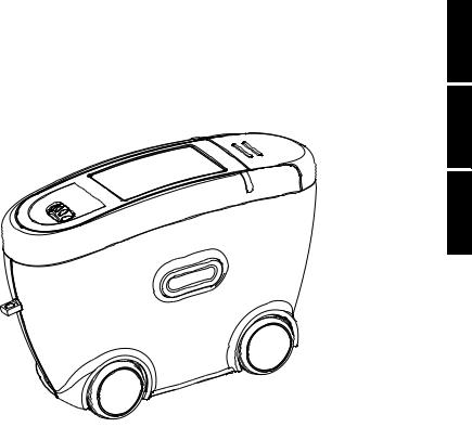
The measurement unit is used to evaluate the appearance of high-quality surfaces (Orange Peel, DOI).
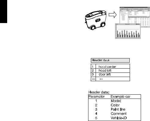
The measurement system consists of the portable measurement device, docking station and the auto-chart program.
English
Depending on the application, the system can be used in various ways, from single measurements in R & D up to routine quality control procedures (e.g. automobile).
In order to guarantee a flexible data analysis, it is essential to allocate the data to a clearly defined object (identification).
The so-called “Organizer” file clearly defines the object to be measured. The Organizer needs to be created in the auto-chart software and defines the measurement sequence (sampling procedure). This file is transferred to the instrument then to guide the user during measurement.
2 |
1 |
8 |
3 |
|
7 |
4 |
|
6 |
|
5 |
|
Organizer
Center Hood n=1/3
L 7.6
S 18.3
11
English
4 |
System description |
The saved results are transferred to the
PC and displayed as a QC report.
The data is saved in a database for further analysis over time. Preprepared test reports in the auto-chart software assist in analyzing the data.
Storage structure
Each measurement series contains a header and the individual measurements with name (test zone) and measured values.
In the header, up to 5 parameters can be defined for object identification. Parameters 1 to 3 are defined in the Organizer file, parameters 4 and 5 can be entered before storage in the data base. Additionally, date and time of the measurement are stored.
This structure determines the data organization in the instrument and in the data base. In addition to using Organizers, i. e. definition of parameters before the measurements, parameters and test zones can also be entered during the measurements. See chapter “Memory”.
12

System description |
4 |
Application hints:
Measurement task
1. Single measurements, e.g. occasional sample-measurements
Recommendation
-Menu “Measure“ > “MEMORY“.
-Transfer results directly to Excel file “wscLink_4“ (auto-chart main directory).
2.Objects with several test zones. Test sequence / identifikation can be standardized, e.g. automobile or addon parts
3.Regular test series. Test sequence / identifikation can be standardized, e.g. batch control
-Generate Organizer in auto-chart and transfer it to the instrument.
-Take readings, see chapter 9.2.
-Transfer results to auto-chart and store in data base.
-Data analysis with “QC reports” in auto-chart.
see 2.
4. Occasional test series. Test sequence / identifikation can not be standardized, e.g. projects
-Generate new Memory (chapter Memory, Config. New).
-Take readings, see chapter 9.1.
-Transfer results directly to Excel file “wscLink_4“ (auto-chart main directory).
English
13
5 |
Control elements |
English |
|
|
2 |
|
3 |
|
1 |
|
4 |
|
6 |
|
5 |
|
7 |
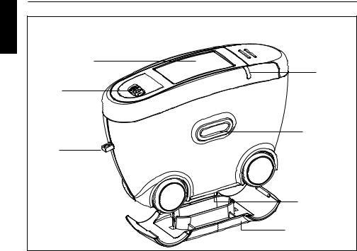
Measurement unit
1Mode scroll wheel: Menu selection
2Display for user guidance and measurement values
3Signal lamp
4Operate button: Turn on, measurement and confirmation of menu items.
5Measurement aperture
6Opening for hand strap
7Cover
14
Control elements |
5 |
The basic system consists of the |
English |
measurement device and the docking |
|
station. |
|
The docking station is used to |
|
exchange data and to charge the |
|
rechargeable battery pack. |
|
When the unit is not in use, place it in |
|
the docking station. In this way the |
|
rechargeable battery pack will be |
|
charged and the instrument will always |
|
be ready for measurements. |
|
The operate button and scroll wheel are used to control the system. Pressing “operate“ turns the unit on and causes a menu to be displayed. All settings within the menus are made by turning the wheel and pressing “operate”.
Pressing the operate button performs measurements or runs selected functions. System operation is supported by an autodiagnosis test, comments and error messages. Measurement values and comments appear in the display.
15 |
6
English
Getting started
Turning the unit on and measuring
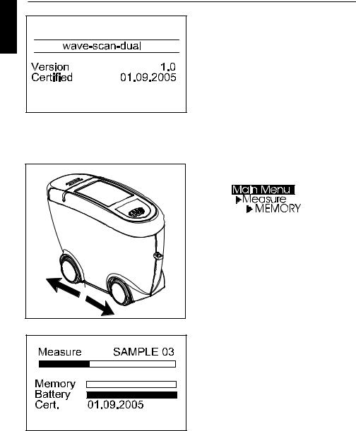
Turn the instrument on by pressing the operate button.
If the operate button is depressed while switching the unit on, a reference to the firmware appears along with the date of the last certification.
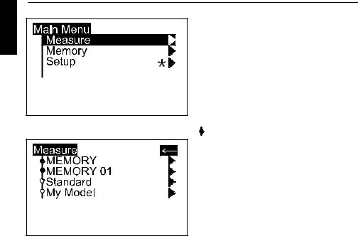
The unit then switches to the last measurement mode to be selected. If no measurement mode has been previously selected, the main menu
appears. For the first steps, select MEMORY under the “Measure” menu.
To perform a measurement, press and hold the operate button.
Move the instrument evenly and slowly over the sample surface.
During the measurement, the following information appears in the display:
The upper bar shows the progress of the measurement. The two lower bars provide information about the status of the memory and battery capacity.
16
Getting started
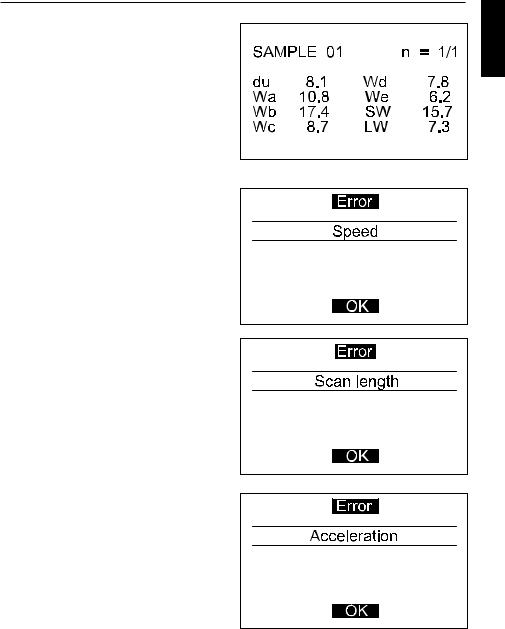
After completing a measurement, the measurement results are displayed. Performing the measurement requires some practice. The following error messages are especially likely to occur during the first trials.
A warning signal is heard and the light diode flashes at a rapid rate. At the same time, a message appears in the display indicating the type of error:
Speed
You have moved the measurement unit too quickly or unevenly over the sample. Confirm this information by pressing the operate button and repeat the measurement.
Scan length
The required scan length has not been reached completely.
Repeat the measurement, moving the device until a short audio confirmation is heard.
Small areas can be measured by moving the instrument back and forth.
Acceleration
The instrument was accelerated too fast across the specimen or the scan direction was changed too fast.
Confirm the message by pressing “operate” and repeat the measurement.
6
English
17
6
English
Getting started
Display of measurement results
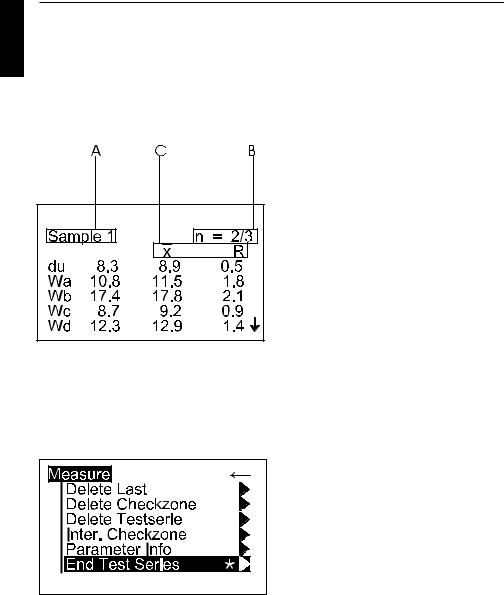
The measurement results displayed will vary depending on the options selected in the Configuration (see chapter 10, 11). Displayed results may be broken down into the following elements:
A: Name of the measured sample or checkzone.
B: The number of performed and predefined measurements (e.g. 2 of 3). The statistic function is activate if the predefined number of measurements is greater than 1.
C: If the statistic function is activated, the selected statistical values appear here.
The measurement values appear in the lower part of the display area.
Pressing the operate button now, the values will disappear and the number of readings is increased by one. Or, if a sample is finished, the name of the next checkzone/sample will be displayed.
To exit the measurements, press the scroll wheel. A menu for deleting, interrupt or ending the series appears. Use the scroll wheel to move the cursor to “End Test Series” and press operate. The display switches to the Measure menu after a request for confirmation.
18

Menu operation |
7 |
|
Navigation |
English |
|
All functions are controlled by the |
||
mode scroll wheel and the operate |
||
|
||
button. |
|
|
Pressing the operate button or the |
|
|
scroll wheel causes a menu to appear |
|
|
in the display. Turning the wheel allows |
|
|
you to move the cursor to the desired |
|
|
function. Select or activate the function |
|
|
by pressing the operate button. |
|
The following symbols can be found throughout the menus to aid navigation:
A black triangle to the right of a function indicates that selecting this function will open a sub-menu.
The arrow at the top right is used to move back one level within the menu system.
A check mark on the right indicates that the function in question has been activated.
In submenus which require a selection, the actual setting is indicated by a dot.
The star guides you to the Language menu.
Arrows pointing up or down indicate that there are other menu options above or below the part of the menu that is visible. To reach these menu options, simply turn the scroll wheel in the direction in which the arrow is pointing.
* |
19 |
7
English
Menu operation
Changing names and numbers
For some functions, you can enter or change the date or name. The triangle pointing upward marks the item that can be changed. To change the character, turn the scroll wheel. When you press the scroll wheel, the arrow jumps to the next character.
After you have adjusted the last character, confirm your input by pressing the operate key.
A confirmation message appears which allows you to save the settings or change incorrect entries. Use “Cancel” to exit the function without making any changes.
20

Overview of Main Menu |
8 |
Measure
MEMORY MY MEMORY
Standard
My Model
Memory
Config. New
Config. Change
Config. Delete
Data View
Data Delete
Setup
Default memory for single measurements
User-defined memory (appears only if generated under “Memory” menu)
To verify the device function on the test panel
Measurement with Organizer (appears only if loaded from PC)
Create a new memory
Change the settings of a memory
Delete a memory
View measured data of a memory
Delete measured data
Change the language, date/time and switch-off time; activate audio signal and confirmation by scroll wheel.
English
21
9 |
Measure |
English |
For beginning a new test series, select |
Measure from the Main Menu. The |
|
Measure menu offers a list of names to |
|
|
identify the new test series (Parame- |
|
ter1). Individual entries can be added |
|
to the list. |
|
Two types of test procedures can be |
|
differenciated by a symbol in front of |
|
the names: |
Memories:
generated in the instrument, allow to input identification parameters during measurement procedure.
 Organizer:
downloaded from the auto-chart software, offer a predefined test procedure for user guidance and identification.
A virgin instrument contains only two entries in the menu, which can not be deleted:
MEMORY - for simple measurement of samples.
Standard - for checking the instrument on the test tile (see chapter 14)
Select a desired item from the list to start the test series and perform the measurements according to section 6.
Differences between the measurement procedures will be explained in chapter 9.1 to 9.3.
22

Measure |
9 |
To exit a measurement series, press |
English |
the scroll wheel. A menu appears for |
|
deleting, interrupt and ending the |
|
series: |
|
Delete Last
Deletes the last measurement within a checkzone.There is no additional warning before the deletion.
Delete Checkzone
Deletes the entire last checkzone. There is no additional warning before the deletion.
Delete Test Series
Deletes the entire measurement series. A confirmation display appears before final deletion.
23

9
English
Measure
Interrupt Checkzone
This function allows you to exit a checkzone/sample before reaching the preset number of measurements or to skip a checkzone. Then you can continue the measurement series with the next checkzone.
If Interrupt is not activated in the Configuration menu (Chapt. 11) or the Configuration of the selected Organizer, a message will be displayed.
Parameter Info
Gives you an information about the selected parameters of the sample.
End Test Series
Ends the entire measurement series. A confirmation display appears. The instrument returns to the Measure menu.
If Interrupt is not activated in the Configuration, a message will be displayed in the case that the test series is not finished yet.
Note:
Only complete series can be saved, i.e. you can exit series only by deletion.
24
Measure
9.1 MEMORY
This is a memory with default settings for single measurements on samples.
The settings can be changed for individual needs, e.g. scale selection, statistics or scan length.
For further information please refer to chapter “Configuration”.
Changes in the configuration are only possible if no measurement data are saved under the desired memory name. Before you change the configuration, first backup the stored data and then delete them.
9
English
25

9 |
Measure |
|
English |
9.2 Organizer |
|
An organizer file defines a test |
||
sequence for user guidance, e. g. for |
||
|
||
|
measuring a car body with several |
|
|
checkzones. These files can be |
|
|
generated with the auto-chart |
|
|
software. |
If no Organizer is loaded in the device, one must be transferred from a PC.
Once an Organizer is selected, a menu appears for Parameter 2 of the Organizer. Colors are listed as an example of this in the menu to the side. After you have selected the appropriate color, a selection menu appears for Parameter 3.
The illustrated example features automotive paint lines.
If “Input Comment” is activated in the Organizer, you are prompted to enter additional information.
If “Input ID” is activated in the Organizer, you are prompted to enter a code, e.g. the vehicle ID.
Upon definition of all parameters, the following measurement series is identified and the instrument goes into measurement mode.
26

Measure
The name of the checkzone to be measured first, appears on the left side of the display.
The number of performed and predefined measurements (e.g. 2 of 3) appear in the upper right corner.
Once the number of measurements for the checkzone is reached, a double audio signal is heard.
The display shows the results of the measurement and indicates that the measurement of the checkzone is complete (e.g.3/3).
Pressing briefly the operate button allows the next checkzone to appear in the display.
The instrument is ready for the next measurement.
Once all checkzones have been measured, the instrument returns to the Measure menu.
9
English
27
9 |
Measure |
|
English |
9.3 Memory with Parameter Input |
|
By using the internal memory function |
||
of the instrument, measurement series |
||
|
||
|
and samples/checkzones can be |
|
|
identified by individual names during |
|
|
the test procedure. |
|
|
Therefore, input options of the menu |
|
|
item Advanced Configuration need to |
|
|
be activated for the desired memory. |
|
|
You can use the existing MEMORY in |
|
|
the instrument or create another |
|
|
memory name (Parameter 1). For |
|
|
more information about change of |
|
|
configuration please refer to section |
|
|
Configuration. |
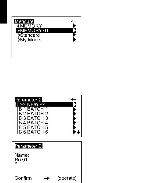
Select a memory for which Input Parameter 2, 3, Input Comment or Input ID are activated. A menu appears to assign a name.
If there are preexisting names for this memory, they are shown in a list for selection. The >>NEW<< option opens another menu with a list of all names available in the instrument. Here, the menu item >>NEW<< opens an input mask which allows you to create a new designation.
Enter the name by using the scroll wheel. When finished, press the operate button.
28

Measure |
9 |
A confirmation display appears which |
English |
allows to verify that the entered data is |
|
correct. |
|
|
|
Next, a selection menu may appear to |
|
enter an additional parameter. |
|
Proceed as described above. |
|
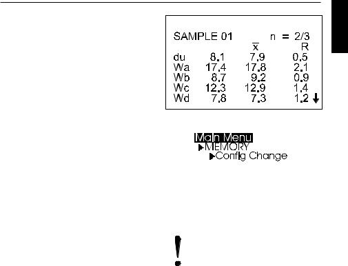
If a memory is selected that already contains measurements, the test series can be continued.
A display appears to confirm this. By selecting No, a new test series will be started.
The device goes to the measurement mode, you can start taking readings.
Once you have reached the preset number of measurements (n = ...), you might be prompted to enter a name for the checkzone (“Input Checkzone” aktivated).
Proceed by entering the name of the checkzone as described above for the parameters.
If “Input Checkzone” is deactivated, the instrument automatically assigns the name SAMPLE 01 and then increments this name.
To exit the test series, presss the scroll wheel and activate End Test Series.
29
 Loading...