


Additives & Instruments
A member of
Measure what you see.
LCM III
Manual
Betriebsanleitung
Mode d’emploi
Istruzioni d´uso

Table of contents
Section 1 Specifications ............... .................................... ................................... .................................... .............. 3
Section 2 General Information .................................. .......................................................... .................................. 5
2.1 Safety information ..................................... .... ... ... ... ... .......................................... ............................................... 5
2.1.1 Use of hazard information .......................................... .......................................... ..................................... 5
2.1.2 Precautionary labels ................................................................................................................................. 5
2.1.3 Chemical and Biological Safety ........................................ ... ... ... .... ... ........................................................ 5
2.2 Overview of product ........................................................................................................................................... 6
Section 3 Installation ............................................................................................................................................. 7
3.1 Unpack the instrument .................................. ... ... .......................................... ... .................................................. 7
3.2 Environment considerations ............................................. ... ... .... ... ..................................................................... 7
3.3 Power connections ....... ... .... ... ... .......................................... ... .... ... ..................................................................... 8
3.4 Connection ............. ... ... ... .... ... ....................................... ... ... ... .... ... ... ... ............................................................... 9
3.5 Cell compartments and cell adapter ................... ... ... .... .......................................... ... ... ... .... ... ......................... 10
3.5.1 Cell compartments and adapter .............................................................................................................. 10
3.5.2 Installation of the cell adapter .................................... ... .... ... ... ... .... ... ... ... ................................................ 11
Section 4 Start Up ................................................................................................................................................ 13
4.1 Power the instrument on and off ...................................................................................................................... 13
4.2 Language selection ................ ... ... .... ... ... ... .... ... ... ... .......................................... ................................................ 13
4.3 Self-Check ................ ... .............................................................................. ... ... ... .... ......................................... 13
4.4 Characteristics in continuous operation ........................................................................................................... 14
Section 5 Standard Operations .................... .......................... .......................... .......................... ......................... 15
5.1 Overview .......................................................................... ... ... .... ... ... ... ............................................................. 15
5.1.1 Tips for the use of the touch screen ..................................... ... ... .... ... ... ... ... .... ... ... ... .... ............................ 15
5.1.2 Use of the alphanumeric keypad ..... .... ... ................................................................................................ 15
5.1.3 Main Menu .............................................................................................................................................. 16
5.2 Instrument Setup mode ....................... ............................. ............................. ................................................... 16
5.2.1 Operator ID ............................................................................................................................................. 16
5.2.2 Sample ID ............................................................................................................................................... 17
5.2.3 Date and time .......................................................................................................................................... 18
5.2.4 Display and sound preferences ........................................... ... ... .... ... ... ... ... .... ... ...................................... 19
5.2.5 Power Management ................................................................................................................................ 19
5.2.6 PC and printer ......................................................................................................................................... 20
5.2.6.1 Printer setup ............................................................................................................................... 21
5.2.6.2 PC setup ..................................................................................................................................... 23
5.2.6.3 Print data .................................................................................................................................... 23
5.2.7 Password ................................................................................................................................................ 24
5.2.7.1 Deactivate a password ............................................................................................................... 25
5.3 Store, recall, send and delete data .................................................................................................................. 26
5.3.1 Auto/manual data storage ....................................................................................................................... 26
5.3.2 Recall stored data from the data log ....................................................................................................... 26
5.3.3 Send data from the data log .................................................................................................................... 27
5.3.4 Delete stored data from the data log ....................................................................................................... 28
5.4 Sampling and sample preparation ................................................................................................................... 29
1

Table of Contents
5.5 Color measurement ......................................................................................................................................... 30
5.5.1 Take a color measurement ..................................................................................................................... 31
5.5.1.1 Touch-sensitive areas on the measurement window .................................................................. 32
5.5.1.2 Parameter setup options ................................ ............. ............. ............ ............. .......................... 33
5.5.1.3 Change the color scale after a measurement .............................................................................33
5.5.2 Determine the Iodine color value ............................................................................................................ 34
5.5.3 Determine the Hazen color value (Pt-Co or APHA-method) ......................... ... .... ... ... ... .... ... ... ... ... .... ... ...34
5.5.4 Determine the Gardner color value ......................................................................................................... 35
5.5.5 Mineral oil color value (ASTM D 1500 and ISO 2049) ............................................ ... ... .... ... ... ................ 35
5.5.6 Determine the Saybolt color number (ASTM D 156) .............................................................................. 35
Section 6 Advanced Operations ............................................................... .......................................................... 37
6.1 System checks ................................................................................................................................................. 37
6.1.1 Instrument information .................. ... ... .......................................... .......................................................... 37
6.1.2 Upgrade of the instrument software ....................... .............................................. ................................... 38
6.1.3 Optical checks ..................... ... ... ....................................... ... .... ... ... ... .... ... ... ............................................. 38
6.1.3.1 Verification kit ................................... ... ... ... .... ... ... ... .... ... ... ... .... ... ................................................ 38
6.1.4 Output checks ..................................................... ... ....................................... ... .... ... ................................ 40
6.1.5 Lamp history ............................. .... ... ....................................................................................................... 40
6.1.6 Factory service ................. ... ... ... .... ... .......................................... ... .......................................................... 41
6.1.7 Service time ..................... ... ... ... .... ... ... ... ....................................... ... .... ... ... ... ... .... ................................... 41
6.1.8 Instrument backup ........................... ... .................................................................................................... 43
Section 7 Maintenance ........................................................................................................................................ 47
7.1 Cleaning requirements ..................................................................................................................................... 47
7.1.1 Housing and cell compartment ............................................................................................................... 47
7.1.2 Display ................... ... ... .... ... ... ....................................... ... ... .... ... ... .......................................................... 47
7.1.3 Cuvettes/sample cells ............................................ ....................................... ... .... ... ... ............................. 47
7.2 Insert or change of the battery ......................................................................................................................... 48
7.2.1 Information about using the battery ........... ... ... ... ... .... ... ....................................... ... ... ... .... ...................... 49
7.2.1.1 Recycle the lithium battery .......................................................................................................... 49
7.2.1.2 Optimal operation of the battery ................................................................................................. 50
7.2.1.3 Lifespan of the battery ...................... ... ... ... .... ... ... ... .... ... ... .......................................................... 50
7.2.1.4 Load the battery/Operating time ....................... ... ... .... ... ... ... .... ... ... ... ... ....................................... 50
7.3 Lamp replacement ........................................................................................................................................... 51
Section 8 Tr oubleshooting .............................................. .............................................................. ......................55
Index ...................................................................................................................................................................... 57
2

Section 1 Specifications
Specifications are subject to change without notice.
Performance specifications
Operating mode Color measurement
DIN 6162 Iodine color value
ISO 6271 Hazen color value
Colorimetric evaluation
Source lamp Gas-filled Tungsten (visible)
Wavelength range 400–700 nm
Wavelength accuracy ± 2 nm
Wavelength calibration Automatic
ISO 4630 Gardner color value
ASTM D 1209 Saybolt color value
ASTM D 1500 Mineral oil color value
Wavelength range for color
measurement
Photometric accuracy
Photometric linearity
Stray light > 3.0 Abs. at 500 nm with OG570/3
Data log 200 color measurements
Physical and environmental specifications
Width 220 mm (8.6 in.)
Height 135 mm (5.3 in.)
Depth 330 mm (12.9 in.)
Weight
Operating requirements 10–40 °C (50–104 °F), max. 80 % relative humidity (non-condensing)
Storage requirements –40–60 °C (-40–140 °F) max. 80 % relative humidity (non-condensing)
Additional technical data
Mains connection
Interfaces
Enclosure rating
400 to 700 nm
5 mAbs at 0.0 to 0.5 Abs
1% at 0.50 to 2.0 Abs
< 0.5 % to 2 Abs
< = 1 % at > 2 Abs with neutral glass at 546 nm
4.06 kg (8.95 Ibs) without battery
4.38 kg (9.66 Ibs) with battery
15 V- / 30 VA
Plug-in power supply unit: (100–240 V/50–60 Hz)
Use only screened cables with maximum length of 3 meters.
1 x USB type A
1 x USB type B
IP 41 with closed lid
IP 42 with Protective Cover in place
Protection Class Safety class II
3

Specifications
4
Section 2 General Information
2.1 Safety information
Please read this entire manual before unpacking, setting up or
operating this equipment. Pay attention to all danger, warning and
caution statements. Failure to do so could result in ser iou s injury to
the operator or damage to the equipment.
To make sure that the protection provided by this equipment is not
impaired, do not use or install this equipment in any manner other
than that specified in this
2.1.1 Use of hazard information
manual.
2.1.2 Precautionary labels
DANGER
Indicates a potentially or imminently hazardous situation
which, if not avoided, will result in death or serious injury.
WARNING
Indicates a potentially or imminently hazardous situation
which, if not avoided, could result in death or serious injury.
CAUTION
Indicates a potentially hazardous situation that may result in
minor or moderate injury.
Important Note: Indicates a situation which, if not avoided, may
cause damage to the instrument. Information that requires special
emphasis.
Note: Information that supplements points in the main text.
Read all labels and tags attached to the instrument. Personal injury
or damage to the instrument could occur if not
if noted on the instrument, will be included with a danger or caution
statement in the manual.
observed. A symbol,
This symbol, if noted on the instrument, references the instruction manual for operation and/or safety information.
Electrical equipment marked with this symbol may not be disposed of in European public disposal systems after
12 August of 2005. In conformity with European local and national regulations (EU Directive 2002/96/EC),
European electrical equipment users must now return old or end-of life equipment to the Producer for disposal at no
charge to the user.
Note: For return for recycling, please contact the equipment producer or supplier for instructions on how to return
end-of-life equipment, producer-supplied electrical accessories and all auxiliary items for proper disposal.
2.1.3 Chemical and Biological Safety
DANGER
Potential Chemical/ Biological Exposure Hazards. Handling
chemical samples, standards and reagents can be dangerous.
Users of this product are advised to familiarize themselves
with safety procedures and the correct use of chemicals, and
to carefully read all relevant Material Safety Data Sheets.
5

General Information
2.2 Overview of product
Normal operation of this instrument may involve the use of
hazardous chemicals or biologically harmful samples.
• The user must observe all cautionary information printed on the
original solution containers and safety data sheet prior to their use.
• All waste solutions must be disposed in accordance with local and
national law.
• The type of protective equipment must be selected according to
the concentration and amount of the dangerous substance at the
specific workplace.
The LCM III is a color measuring instrument for determin the color
values of transparent, optically clear liquids. The instrument comes
with a complete set of application programs and multi-language
support.
The LCM III can carry out an exact colorimetric evaluation in
conformity with ISO/ASTM standards with just a single
measurement and display the result in terms of traditional color
systems such as Iodine, Hazen or Gardner color numbers.
6

Section 3 Installation
WARNING
Electrical and Fire Hazards. Use only the provided power
supply. Only qualified personn el should conduct the tasks
described in this section of the manual.
3.1 Unpack the instrument
The LCM III comes packaged with the following items:
• LCM III
• Dust cover
• External power supply, including 4 adapter for EU, UK, USA
• cuvette/cell adapter Z
• LCM III user manual
Note: If any of these items are missing or damaged, contact the
manufacturer or a sales representative immediatly.
3.2 Environment considerations
The following conditions are necessary to make sure correct
instrument operation and accurate resu lts:
• Place the instrument firmly on an even surface. Do not push
and AUS/China
any objects under the instrument.
• Maintain an ambient temperature of 10 to 40 ºC (50 to 104 ºF)
for proper instrument operation.
• The relative humidity should be less than 80 %; moisture
should not condense on the instrument.
• Leave at least a 15 cm (6 in.) clearance at the top and on all
sides for air circulation to avoid overheating of electrical parts.
• Do not operate or store the instrument in extremely dusty,
damp or wet locations.
• Keep the surface of the instrument, the cell compartment and
all accessories clean and dry at all times. Splashes or spills on
and in the instrument should be cleaned up immediately (see
section 7.1 on page 47).
• After a continuous operating time of more than 24 hour without
switching off the instrument we recommend to perform a new
calibration with a distilled water cuvette/sample cell.
• After a continuous operating time of more than 7 days without
switching off the instrument we recommend to switch off an d on
the instrument to perform a new system check with filter
adjustment and lambda-calibration.
Important Note: Protect the instrument from temperature
extremes, including heaters, direct sunlight and other heat sources.
7

Installation
3.3 Power connections
Install the correct adapter plug on the supplied external power
supply (
Correctly mounted, both housing of power supply and plug are in
line. Plug the external power supply cord into the connector on the
back panel of the instrument, then plug the supply into a power
outlet (100–240 V~ / 50–60 Hz). Press the power switch on the
back of the instrument to initialize power (
Figure 1). Slide the adapter on until it "clicks" into position.
Figure 2 on page 9).
Figure 1 Power adapter
1 Power supply with EU adapter plug installed 3 USA adapter plug
2 UK adapter plug 4 AUS/China adapter plug
8
3.4 Connection
Installation
The LCM III has two USB interfaces as a standard feature, located
on the back of the instrument (
The USB Type A interface is used for communications with a
printer, USB memory stick or keyboard. A USB memory stick is
used to update instrument software.
The USB Type B interface is used for communications with a PC.
The optional Data Trans software must be installed on the PC for
this use.
A USB hub may be used to connect several accessories at a time.
Note: USB cables must not be longer than 3 meters (10 feet).
These USB interfaces enable data and graphics to be output to a
Printer and a PC and upgrade instrument software (see
section 6.1.2 on page 38).
Figure 2).
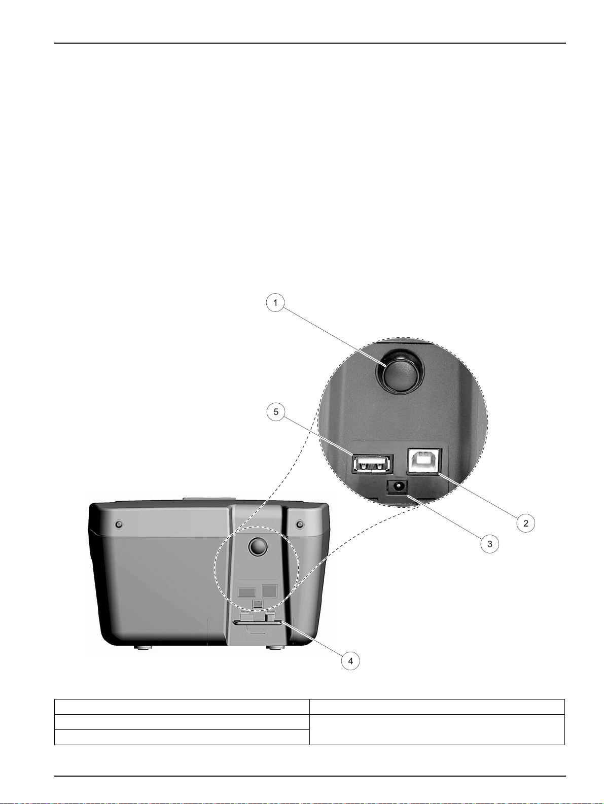
Figure 2 Interfaces
1 On/Off switch 4 Cover
2 USB type B 5 USB type A
3 Plug in power supply
9

Installation
3.5 Cell compartments and cell adapter
3.5.1 Cell compartments and adapter
The LCM III has two cell compartments (Figure 3). Only one
cuvette/sample cell type at a time can be used for a measurement.
Cell compartment #1
• 11-mm round cuvettes/sample cells
For measurements with 11 mm round cuvettes/sample cells in
cell compartment #1 insert the adapter Z into cell
compartment #2.
Cell compartment #2
Cell compartment #2 uses adapters to accommodate different
cuvette/sample cell types.
• 50 mm rectangular cuvettes/sample cells (can be inserted
directly into the cell compartment without using an adapter).
• 10 mm square cuvettes/sample cells (can be inserted with the
adapter Z)
Important Note: Be sure that the adapter Z is inserted proper into
the cell compartment. Press the adapter down until it snap into the
compartment.
Figure 3 Cell compartments
1 Cell compartment #1 2 Cell compartment #2
10

1 Adapter Z: 10 mm square cell adapter
Installation
Figure 4 Cell adapter Z
3.5.2 Installation of the cell adapter
1. Open the cell compartment.
2. Insert the adapter for measurements with the round
cuvette/sample cell (11 mm) and/or 10 mm square
cuvette/sample cell so the arrow on top of the adapter po int s to
the left (Figure 4) and the orientation tab fits the groove in the
compartment opening.
Note: The arrow on top of the adapter indicates the direction of the light
beam path.
11

Installation
12

Section 4 Start Up
4.1 Power the instrument on and off
1. Plug in to the power supply (laboratory analysis) or insert the
battery (field analysis).
2. The push-button switch on the back of the instrument switches
the instrument on (press for about 1 second) and off (press for
about 3 to 5 seconds). An acoustic signal confirms that the
instrument has been switched off.
Note: Do not turn the instrument off and on in rapid succession. Always
wait about 20 seconds before turning the instrument on again, otherwise
the electronic and mechanical systems will be damaged.
4.2 Language selection
The LCM III software includes several language options. The first
time the instrument is turned on, the language selection screen will
appear.
4.3 Self-Check
1. Select the desired language.
2. Press OK to confirm. The self-check will start automatically.
Changing the language setting
The instrument functions in the selected language until the option is
changed.
1. While turning the instrument on, touch the screen at any point
until the list for selecting a language appears (about
30 seconds).
2. Select the required language.
3. Press OK to confirm. The self-check will start automatically.
Each time the instrument is powered, a series of diagnostic tests
are performed automatically to make sure operation of major
system components.
This procedure, which takes approximately two minutes, checks the
system, lamp, filter adjustment, wavelength calibration and volt age.
Each test which functions correctly is confirmed with a check mark.
Note: For further error messages during self-check, see Section 8 on page
55.
13

Start Up
The Color Measurement Menu is displayed when diagnostics are
completed. Insert a cuvette/sample cell with distilled water to
calibrate.The calibration starts automatically when the LCM III
recognizes a 11 mm round vial in the cell compartment #1. For the
use of square cuvettes/sample cells in the cell compartment #2,
press Start to start the calibration.
Insert the sample cuvette/cell. For the use of 11 mm round vials the
measurement starts automatically. For the use of square
cuvettes/sample cells in the cell compartment #2, press Measure to
start the measurement.
See section 5.1.3 Main Menu on page 16 for a detailed description.
4.4 Characteristics in continuous operation
After a continuous operating time of more than 24 hour without
switching off the instrument we recommend to perform a new
calibration with a distilled water cuvette/sample cell.
After a continuous operating time of more than 7 days without
switching off the instrument we recommend to switch of f and on the
instrument to perform a new system check with filter adjustment
and lambda-calibration.
14

Section 5 Standard Operations
5.1 Overview
5.1.1 Tips for the use of the touch screen
The entire screen is touch-activated. T o make a selection, press the
screen with a fingernail, fingertip, pencil eraser or a stylus. Do not
press the screen with a sharp object, such as the tip of a ball
point
pen.
• Do not place anything on top of the screen, to prevent damage
or scratching on the screen.
• Press keys, words or icons to select them.
• Use scroll bars to move up and down long lists very quickly.
Press and hold the scroll bar, then move up or down to move
through the list.
• Highlight an item from a list by pressing it once. When the item
has been successfully selected, it will be displayed as reversed
text (light text on a dark background).
5.1.2 Use of the alphanumeric keypad
This display is used to enter letters, numbers and symbols as
needed when programming the instrument. Unavailable options are
disabled (grayed out). The icons on the right and left of the screen
are described in
The central keypad changes to reflect the selected entry mode.
Press a key repeatedly until the desired character appears on the
screen. A space can be entered by using the underscore on the
YZ_ key.
Note: A USB keyboard (with US keyboard layout) or a USB Barcode
handset scanner can be used for input.
Table 1 Alphanumeric keypad
Icon / key Description Function
ABC/abc Alphabetic
# % Symbols Punctuation, symbols and numerical sub- and superscripts may be entered.
123 Numeric For entering regular numbers.
CE Clear Entry Clear the entry.
Left Arrow Backspace
Right Arrow Advance
When entering alphabetic characters (ex. user-entered units), this key allows to
toggle between upper and lower case letters.
Moves back one position. This deletes the character previously entered in the new
position.
Moves to the next space in an entry when two adjacent characters occur on the
same key.
Table 1.
15

Standard Operations
5.1.3 Main Menu
A variety of modes may be selected from the Main Menu. Table 2
briefly describes each menu option.
Table 2 Main Menu options
Option Function
Color Measurement
System Checks
Recall Data Stored data can be recalled, filtered, sent to Printer, Memory stick or PC and deleted.
Instrument Setup
The COLOR MEASUREMENT mode is used to determine visual color values like Hazen,
Gardner and Saybolt
The system checks menu offers a number of options, including optical checks, output checks,
lamp history, instrument update, service time and instrument backup.
In this mode, user-specific or method-specifi c settings can be entered: Operator-ID, Sample-ID,
Date & Time, Display & Sound, PC & Printer, Password
5.2 Instrument Setup mode
5.2.1 Operator ID
1. Select Instrument Setup in the Main Menu.
A selection of configuration options appear.
Use this option to enter up to 30 sets of operator initials (up to five
characters each). Also the color can assigned for each Operator ID.
This feature helps record which operator measured each sample.
16

Standard Operations
1. Press Operator ID in the Instrument Setup.
2. Press New to enter a new Operator ID.
3. Use the alphanumeric keypad to enter a new Operator ID.
4. Press OK to confirm.
5. The display shows the selected Operator ID.
6. Press OK to return to Instrument Setup.
7. The selected Operator ID is activated.
5.2.2 Sample ID
Note: Press Delete to remove an Operator ID from the list.
Note: Alternatively , enter or change an Operator ID in measurement mode.
In the results screen, press Options>More>Instrument Setup or if an
Operator ID is already assigned, select the Operator ID symbol
immediately in the results screen.
Use this option to enter up to 100 Sample Identification tags (up to
13 characters each) into the instrument. Sample IDs can be used to
specify the sample location or other sample specific information.
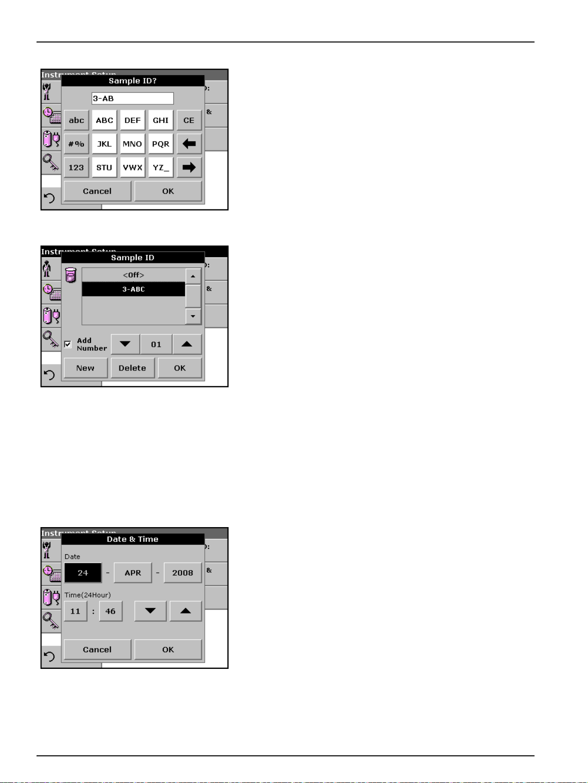
1. Press Sample ID in the Instrument Setup.
2. Press New to enter a new Sample ID.
17
Standard Operations
3. Use the alphanumeric keypad to enter a new Sample ID.
Note: If a USB Barcode handset scanner is connected, Sample IDs
can also be scanned.
4. Press OK to confirm.
5. To number the Sample IDs sequentially (e.g. Inflow (01 etc.)),
select Add Number.
• Use the arrow keys to specify the first number of the
sequence.
5.2.3 Date and time
• Use the key between the arrow keys to enter the first
number of the sequence using the alphanume ric ke ypad.
6. Press OK to return to Instrument Setup.
7. The Sample ID is activated. Each Sample ID is automatically
numbered in ascending order after a measurement. The
number is shown in parentheses behind the Sample ID.
Note: To remove a Sample ID, highlight the ID and press Delete.
Note: A Sample ID can be entered or changed in measurement mode. In
the results screen, press Options>More>Instrument Setup. If a Sample
ID is already assigned, select the Sample ID symbol in the results screen.
1. Press Date & Time in the Instrument Setup.
2. The date and time are subdivided over a number of fields.
Press the appropriate field and use the arrow keys to change
the value.
18
3. Press OK to return to Instrument Setup.

5.2.4 Display and sound preferences
1. Press Display & Sound in the Instrument Setup.
The following options will be displayed:
• Display Contrast—Adjusts the display brightness to suit
• Screen touch—Activates//Deactivates a short beep each time
• Reading done—Activates/Deactivates a sound when a
•Timer—Adjusts the length of the timer sound. Select Short or
2. Select Long to change the number of audio signals.
Standard Operations
lighting conditions.
the screen is pressed (Default:off).
reading is complete (Default: short beep every time a reading is
complete).
Long. Long beeps are recommended for noisy environments.
5.2.5 Power Management
Use the alphanumeric keypad to enter/specify the number of
audio signals (4–25).
Note: A high number of audio signals increases the duration of the
tones and a small number of audio signals reduces the duration of the
tones.
3. Press OK to confirm. The selected number of the audio signals
sounds as a corresponding acoustic signal.
4. Press OK to return to Instrument Setup.
The LCM III can run on mains or battery power.
Note: The battery is not part of the standard scope of delivery.
1. Select Power Management in the ”Instrument Setup“ menu.
The battery symbol indicates the charge status of the battery
in
%.
Note: The timer settings in the Power Management menu are only
active when the instrument is runn i n g on ba ttery power.
19

Standard Operations
2. Select one of the options under Standby mode to set the
length of the idle period that can elapse before the instrument
switches to the Standby mode when running on battery power.
Note: In standby mode, the backlighting of the screen is switched off.
Touching the display causes the lighting to switch on again.
3. Select one of the options under Auto off to set the length of the
idle period that can elapse before the instrument automatically
switches off when running on battery power.
After the instrument switches itself off automatically, you have to press the
push-button switch on the back of the instrument to start it again.
5.2.6 PC and printer
The LCM III is provided with 2 USB interfaces, which are located on
the back of the instrument (see
interfaces can be used for exporting data and graphics to a printer,
updating data and for data communication to a personal computer.
These interfaces can be used for the connection of a USB stick, an
external USB keyboard or a USB Barcode handset scanner.
Note: A USB hub may be used to connect several accessories at a time.
A USB memory stick is used to upgrade data, see section 6.1.2 on
page 38.
Important Note: A screened USB cable must not be longer than
3
m!
Table 3 USB connector
USB Interfaces Description
USB (Type B)
USB (Type A) This USB port can be used to connect a printer, a USB memory stick and keyboard.
This USB interface is only intended for the LCM III to PC connection (with installation of the Data
Trans Software).
Figure 2 on page 9). These
20

5.2.6.1 Printer setup
Standard Operations
1. Press PC & Printer in the Instrument Setup.
A list with information about the connections opens.
For reasons of compatibility, the printer language must be
HP
PCL 3.
1. Press Printer.
2. Press Setup to display the Printer Setup screen.
Printer Setup:
• Resolution: Font size
• Paper: Paper size
Note: If an optional Thermal Printer is connected, the function "Auto Send"
on/off is available.
21

Standard Operations
3. Select Auto-Send: On to send all measured dat a automatically
to the Thermal printer.
Note: The option Auto-Send is not available for any other printer (e.g. ink
jet printer).
4. Press Resolution to select the print quality.
Select between
• 100 dpi
• 150 dpi
• 300 dpi
5. Press OK to confirm.
Note: Press OK again to return to the Instrument Setup menu.
6. Press Paper to select the paper size.
Select between
• Letter
• Legal
• Executive
• A4
7. Press OK to confirm.
Note: Press OK again to return to the Instrument Setup menu.
22
5.2.6.2 PC setup
Standard Operations
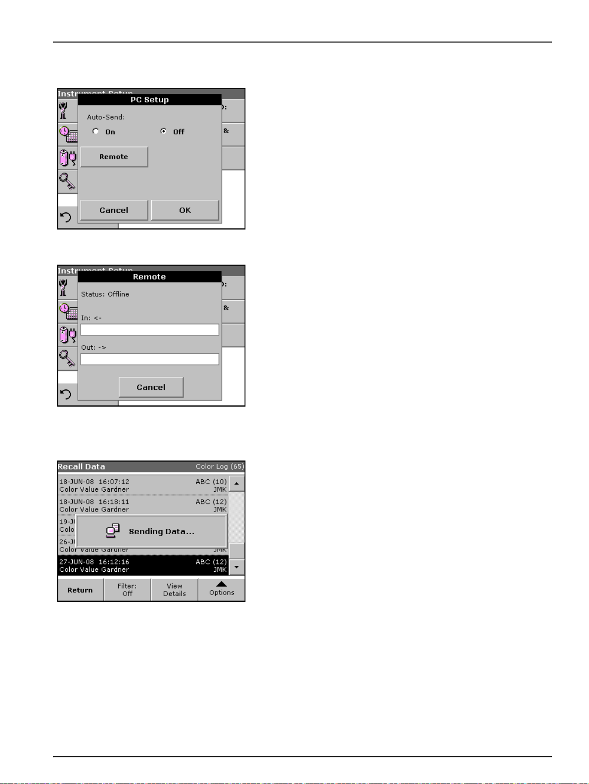
1. Press PC.
2. Press Setup to display the PC Setup screen.
3. With Auto-Send ON selection each measurement result will be
automaticly sent to a PC.
4. Select Remote to etablish a bi-directional PC connectio n to
send and receive commands and data (reserved for advanced
application).
5.2.6.3 Print data
1. Press Recall Data in the Main Menu.
2. Select the data source, where the data to be printed are stored.
3. A list is displayed. Data can be filtered. For more information
see 5.3.2 Recall stored data from the data log on page 26.
4. Press the Printer icon.
5. Highlight Single point or Filtered data or All data and press
OK to confirm.
6. Sending Data is displayed until the data have been printed.
23

Standard Operations
5.2.7 Password
The Password menu contains a variety of security settings to
control access to various functions. For example, prevent
unauthorized changes to stored programs or instrument
configurations.
1. Press Password in the Instrument Setup menu.
2. In order to highlight the Security List assign a password. Press
Set Password.
3. Use the alphanumeric keypad to enter a new Password (up to
10 characters each) and press OK to confirm.
The access to the Security List is activated.
4. Press Security List to lock various functions for unauthorized
users.
24

5.2.7.1 Deactivate a password
Standard Operations
5. Highlight the desired functions to control.
6. Confirm the Security List with OK to return to the Password
menu.
7. Press On to highlight the new settings of the Security List.
8. Enter the new Password again to confirm.
9. Press OK to return to Instrument Setup.
Note: The alphanumeric keypad to the Password inquiry appears when a
user tries to reach a locked setting.
1. Press Password in the Instrument Setup.
2. Use the alphanumeric keypad to enter the former Password
and press OK to confirm.
3. Press Off to deactivate the settings of the Security List.
4. Press OK to return to Instrument Setup.
Note: Use this function to delete the former Password or to enter a new
one.
25

Standard Operations
5.3 Store, recall, send and delete data
The Data Log will store up to 200 color measurments taken in the
Color Measurements modes.
A complete record of the analysis is stored, including the Date,
Time, Results, Sample
5.3.1 Auto/manual data storage
The data storage parame ter indicates whether dat a are to be stored
automatically or manually (in which case the user has to decide
which data to store).
ID and Operator ID.
1. Press Store: On/Off in the Options menu.
•Store On setting: All measurement data are stored
•Store Off setting: No measurement data are stored.
Note: When the instrument memory (data log) is full, the oldest data are
automatically deleted allowing the new data to be stored.
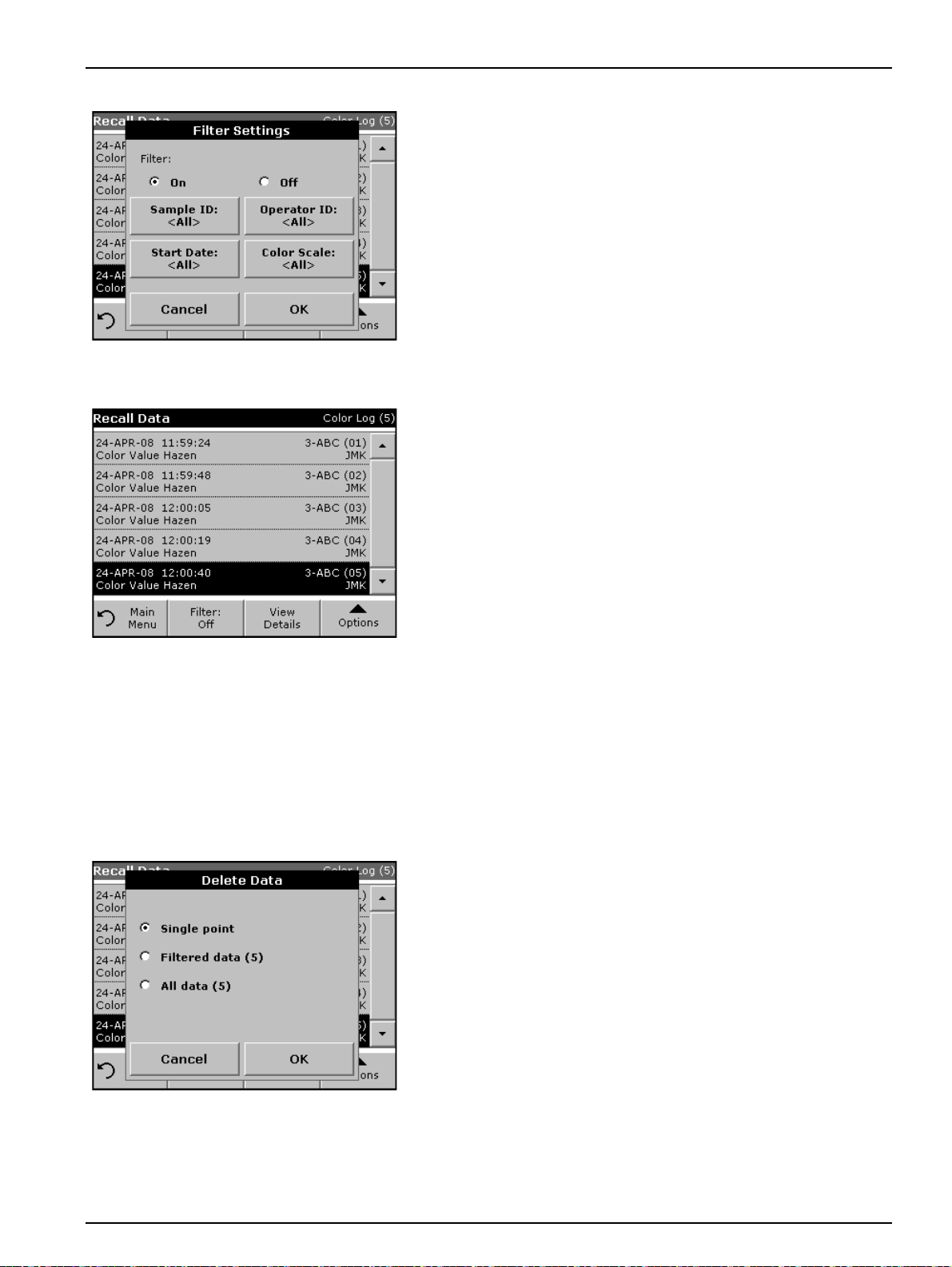
5.3.2 Recall stored data from the data log
1. Press Recall Data in the Main Menu.
2. Press Data Log.
A listing of the stored data is displayed.
3. Press Filter: On/Off.
automatically.
However, this setting can be changed to Store On in the
result display through Configuration. The reading currently
shown in the display is then stored.
26
Standard Operations
4. The function Filter Settings is used to search for specific
items.
5. Highlight On to turn on the filters to select data by
• Sample ID
• Operator ID
• Start Date
• Color Scale
or any combination of the four.
6. Press OK to confirm the selection. The selected items are
listed.
7. Press View Details to get more information.
5.3.3 Send data from the data log
8. Turn on the filter to select data by Color Scale.
Data is sent from the data log as CSV (Comma Separated Value)
files through a USB memory stick to a file named DATALOG. The
file can then be processed using a spreadsheet program. The file
name will be formatted as:
DLYear_Month_Day_Hour_Minute_Second. CSV.
To send data to a Printer, see section 5.2.6.3 on page 23.
1. Plug in the USB device (Figure 2 on page 9).
2. Press Recall Data from the Main Menu. Press Options and
then the PC & Printer icon.
3. Select the data to send to the memory stick and press OK.
Note: The number in parenthesis is the total number of data sets
assigned to this selection.
To send measurement data to a PC:
The optional Data Trans software must be installed on the PC for
the subsequent to process for meas u re m en t da ta.
27

Standard Operations
1. Press PC & Printer in the Instrument Setup.
2. Select PC.
3. Press Setup to display the PC Setup screen.
For further installation instructions, refer to the Data Tr ans user
manual.
4. Select Auto-Send: On to send all measured dat a automatically
to the PC.
Note: If Auto-Send: Off is selected, the "PC & Printer" key must be
pressed, in order to send data to the PC.
The remote function is only for monitoring the data transfer.
5.3.4 Delete stored data from the data log
1. Press Recall Data in the Main Menu.
2. Press Data Log, then Options>Delete.
3. Highlight Single Point or Filtered data or All data and press
OK to confirm.
Note: The number in parentheses is the total number of data sets
assigned to this selection.
28

5.4 Sampling and sample preparation
Take a representative sample from the product you want to
measure in accordance with DIN EN ISO 15528 (or ASTM
D3925-02).
If the material shows any visual haziness, remove the haze by
either filtration, centrifugation, heating, ultrasonic treatment or
suitable means.
Heat partly solid samples before measuring in order to dissolve the
solid material in the liquid. The preparation must not cause any
chemical changes in the sample.
Make sure that during the measurement are no bubbles in the
sample.
There are three cuvette/sample cell types available for color
measurement with the LCM III, differing by material (glass, PS and
PMMA) and path length (10 mm,11 mm and 50 mm). Fill the
cuvette/sample cell to approximately 2 cm. The light beam passes
through the cuvette/sample cell around 0.5 cm to 1.5 cm above the
base of the cuvette/sample cell.
The program calculates and displays Iodine, Hazen, Gardner,
Saybolt, Klett and ASTM D 1500 color values automatically, taking
into account the cuvette/sample cell type.
Standard Operations
A dry thermostat is available for the 11 mm disposable round glass
cuvettes/sample cells. The dry thermostat heats the
cuvettes/sample cells to any temperatur e be tween ambiant and
150 °C.
Important Note: The samples must be clear and free of turbidities.
If products in paste or solid form cannot be measured directly, the
product must be melted before being transferred to the
cuvettes/sample cells. Make sure the cuvettes/sample cells do not
contain any air bubbles.
• Always hold the cuvette/sample cell close to the top, to make
sure that there are no fingerprints in the measurement zo ne of
the cuvette/sample cell. Use suitable transfer pipettes to
introduce samples into the cuvettes/sample cells.
• Slowly add samples to the cuvettes/sample cells cells to make
sure air bubbles do not form on the cuvette/sample cell wall
and in the sample. Air bubbles will cause false readings.
• If air bubbles are entrapped, remove them by heat, vacuum,
ultrasonic treatment or other suitable means.
• Clean the outside of the cuvettes/sample cells thoroughly
before inserting them in the cell compartment.
Important Note: Before using disposable cuvettes/sample cells
made by PS (Polystyrene) or PMMA (Polymethyl methacrylate) be
sure that the cuvettes/sample cells will not be destroyed by
samples, otherwise the cell compartment can be damaged.
29

Standard Operations
5.5 Color measurement
Proper sample preparation is extremely importa nt for accurate color
measurement. To make sure an accurate measurement is taken,
refer to the following sample preparation guidelines:
• Always clean the glass cuvettes/sample cells immediately after
use.
• Only use optically preferred samples for measurement. Make
sure the cuvette/sample cell are clean and show no signs of
opaqueness.
• Slowly fill the liquid into the cuvette/sample cell to prevent air
bubbles in the sample.
• Refer to section 5.4 on page 29 for more sample and sampling
preparation information.
The Color Measurement mode is used to determine absolute color
values in the Hazen or Gardner.
The LCM III uses an independent calibration data set for each type
of cuvette/sample cell size (11 mm round vial and 50 mm
rectangular cells).
It is possible to calibrate the instrument with one, two or three types
of cuvettes/sample cells and to use these different cuvette/sample
cell types in parallel.
For the use of the 10 mm square cuvette/sample cell and 11 mm
round vials it is necessary to insert the adapter Z into the cell
compartment #2. For measurements with 50 mm rect angular
cuvettes/sample cells please remove the adapter.
The cell compartment #1 has an automatically cell detection. For
use of the 11 mm round vial in the cell compartment #1 the
measurement starts automatically.
For the use of square cuvettes/sample cells in the cell compartment
#2, press Start or Measure to start the measurement.
30

5.5.1 Take a color measurement
Standard Operations
1. Press Color Measurement.
2. Insert a cuvette/sample cell with distilled water to calibrate.
Important Note: Carried out the calibration always very carefully,
as a faulty calibration can cause inaccurate results to be obtained.
3. The calibration starts automatically when the LCM III
recognizes a 11 mm round vial in the cell compartment #1.
For the use of square cuvettes/sample cells in the cell
compartment #2, press Start to start the calibration.
4. The type of cuvette/sample cell and the actual progress of
calibration is shown in a seperat window.
5. After the calibration is done the screen shows an empty
measurement window. In the upper right corner of the window
the selected cuvette/sample cell size is displayed. The middle
button changes to Measure.
31

Standard Operations
6. Insert the sample cuvette/cell.
For the use of 11 mm round vials the measurement starts
automatically.
For the use of square cuvettes/sample cells in the cell
compartment #2, press Measure to start the measurement.
7. The result of the color calculation is displayed.
Note: The control bar displayed on the right of the displayed result
shows the relationship of the measurement result to the measuring
range.
8. For the next measurement, remove the cuvette/sample cell and
insert the next sample cuvette/cell or press Measure to
measure the same sample again.
5.5.1.1 Touch-sensitive areas on the measurement window
On the screen are touch-sensitive areas where the user has
immediate access to special software options.
Figure 5 Touch-sensitive areas on the measurement window
1 Open Operator ID to change or add operator ID
(see section 5.2.1 on page 16 )
2 Open Sample ID to change or add sample ID
(see section 5.2.2 on page 17)
3 Open Select Color Scale and select scale for
display (see section 5.5.1.3 on page 33)
4 Change the displayed color scale to the next color
system which is selected in the Operator ID color
scale list for display. (see section 5.5.1.3 on page
33)
5 Change Date & Time (see section 5.2.3 on page
18)
6 Open Power Management to indicate the charge
status of the battery in %. (see section 5.2.5 on
page 19)
32

5.5.1.2 Parameter setup options
Table 4 Stored programs options
Options Description
More For further Options
Store: On
With the STORE ON setting, all measurement data are stored automatically. With the STORE OFF
setting, no measurement data are stored.
Standard Operations
Press Option for Parameter Setup.
Send Data To send data to a printer, computer or USB memory stick (Type A)
Color Scale Select the color scale
Send Data To send data to a printer, computer or USB memory stick (Type A)
Color Scales for
Operator ID
Configure the color scale for the display and for print.
5.5.1.3 Change the color scale after a measurement
1. Press the touch-sensitive area 3, e.g. Color Value Hazen.
33

Standard Operations
2. A list of all color scales is displayed.
3. Select the required scale .
4. Press OK to confirm.
5. The current result of the actual reading and all further
measurements will be displayed in the selected color scale.
5.5.2 Determine the Iodine color value
DIN 6162 defines the Iodine color value as mg of iodine per 100 mL
of potassium iodide solution. Color matching with the Iodine color
determines the depth of color of clear liquids like solvents,
plasticisers, resins, oils and fatty acids, whose color is similar to
that of a solution of iodine and potassium iodide of the same
thickness.
For iodine color values of less than or approximately 1, the
determination of the Hazen value according to DIN-ISO 6271 is to
be preferred. Sampling and preparation are described in section
on page 29.The Iodine value can be accurately determined using
an 11 mm round glass cuvette/sample cell.
5.5.3 Determine the Hazen color value (Pt-Co or APHA-method)
The Hazen color value (ISO 6271, also known as "AHPA-method "
or Platinum-Cobalt Scale) is defined as mg of platinum per 1 litre of
solution. The Hazen parent solution is composed of 1.246 g of
potassium hexachloroplatinate (IV) and 1.00 g of cobalt(II)chloride
dissolved in 100 ml of hydrochloric acid and filled up to 1000 ml with
distilled water.
The Hazen-color scale is used to evaluate the colors of nearly
water-clear products. It has narrower gradations in the light yellow
range than the Iodine scale and extends to water-clear color casts.
5.4
34
Note: Samples with Hazen values between 50 and 1000 can be measured
with sufficient accuracy in 10 mm square and 11 mm round

cuvettes/sample cells. Hazen values below 50 are measured in 50 mm
cuvettes/sample cells. Hazen values below 10 are only be measured with
the 50 mm cuvette/sample cell used for calibration, because nearly
water-clear products can easily give faulty measuring results due to
cuvette/sample cell tolerances.
5.5.4 Determine the Gardner color value
The Gardner color value is defined in DIN-ISO 4630.The lighter
Gardner color values (1 to 8) are based on
potassium-chloroplatinate solutions, while the darker ones (9 to 18)
are based on solutions of iron(III)chloride, cobalt(II)chloride and
hydrochloric acid. The LCM III can determine Gardner values at all
cuvette/sample cell path lengths (only values 0 to 4 in 50 mm
cuvettes/sample cells).
The 10 mm and 11 mm cuvettes/sample cells provide sufficient
accuracy.
5.5.5 Mineral oil color value (ASTM D 1500 and ISO 2049)
The mineral oil color scale is used to evaluate the color of mineral
oil products such as lubricating oils, fuel oil, diesel fuel and paraf fin.
The color scale starts at color value 0 for water-white, non-colored
oils and ends at 8 for very dark brown oils. Substances are visually
evaluated in multiples of 0.5 (0.5; 1.0; 1.5 etc.).The LCM III displays
the results in multiples of 0.1. For samples whose color value is
higher than 8,*** is displayed.
Standard Operations
Note: Because of the intensive color of the ASTM D 1500 color value, it is
calculated only for 11 mm round or 10 mm square cuvettes/sample cells.
No calculation is carried out for the 50 mm path length.
5.5.6 Determine the Saybolt color number (ASTM D 156)
The Saybolt color scale is used to evaluate refined oil products
such as petrol and kerosene, as well as for petroleum waxes and
pharmaceutical white oils.
The Saybolt color properties are comparable to those of the Hazen
scale (APHA). The Saybolt color scale starts at color number +30
(lightest color , equivalent to approximate ly 8 to 10 Hazen) and ends
at -16 (strongest color, equivalent to approximately 350 Hazen).
Note: The measurements can be carried out with 10 mm, 11 mm or 50 mm
cuvette/sample cell path lengths. A longer path length increases the degree
of accuracy associated with the measurements (50 mm recommended).
35

Standard Operations
36

Section 6 Advanced Operations
6.1 System checks
1. Press System Checks in the Main Menu.
The System Checks menu contains instrument information and
various performance tests.
6.1.1 Instrument information
1. Press Instrument Information in the System Checks menu.
2. The model, serial number and software version are displayed.
37

Advanced Operations
6.1.2 Upgrade of the instrument software
1. Go to http://www.hach-lange.com
2. Select the country and go to Download>Software.
3. Enter LCM III in ”Search for documents“.
4. Locate the appropriate download and follow the prompts for
saving the file(s) to the USB memory stick or to the PC.
5. Unpack the ZIP file and save the files to the USB mem ory st ick .
6. Press Instrument Update in the System Checks menu.
7. Connect the USB memory stick to the USB interface (type A)
on the instrument, see section 3.4 on page 9.
8. Press OK. The link is established automatically and the
software is updated.
6.1.3 Optical checks
6.1.3.1 Veri fication kit
9. Press OK to return to the System Checks menu.
Note: When the instrument software has been updated, a prompt to restart
the instrument is displayed.
1. Press Optical Checks in the System Checks menu.
The Optical Checks menu for checking the wavelength accuracy,
stray light and photometric accuracy.
An test filter set (Verification Kit) containing four precision glass
filters, target values and instructions is available as an aid for
carrying out comprehensive in-house instrument checks.
The Verification Kit is desig ned for periodic monitoring of scattered
light, photometric accuracy and the wavelength accuracy of the
spectrophotometers.
38
When results exceed allowable tolerances (given in the quality
control certificate to the test record), contact the manufacturer.

Advanced Operations
1. Press Nominal Values.
2. Press Edit.
An automatic menu guidance queries values (filters,
wavelength, nominal values and tolerances) given in the quality
control certificate, to the following specifications:
• Stray Light
• Photometrical accuracy
• Wavelength accuracy
3. Press OK when all values are entered and the overview is
displayed.
4. Press Verification.
5. Insert the adapter Z (Figure 4 on page 11) in
cell compartment #2.
39

Advanced Operations
6. Remove any cuvettes/sample cells from the cell compartment
and press Start.
7. Insert the different filter in the given order one after the other.
Press Next after inserting a filter.
6.1.4 Output checks
6.1.5 Lamp history
After the last measurement the results are displayed.
8. Press PC & Printer icon to send the data to a USB memory
stick, PC or to a printer.
The files will be stored automatically as CSV file (Comma
Separated Value). The file name will be formatted as
“Verification.csv“.
If a printer is connected a test printing of the current screen will be
printed.
The Lamp History menu provides the amount of time that the lamp
has been on (Hours).
40

6.1.6 Factory service
Advanced Operations
After a lamp is replaced, the display of the total operating time is
reset to 0.
1. Press Lamp History in the System Checks menu.
2. Press Reset VIS and the Visible Lamp will be reset.
3. Press OK to return to System Checks.
The Factory Service menu is password protected. This menu is not
intended for customer use.
6.1.7 Service time
In order to make sure a regular inspection, an automatic memory
reference for the service times can be entered. After switching the
instrument on this memory reference will be activated and indicated
at the appropriate time.
1. Press Service Time in the System Checks menu.
2. Select On and then Last Service to enter the date of the last
inspection.
3. Press OK to confirm.
41

Advanced Operations
4. Select Next Service to determine a specific period of time up to
the next inspection.
5. Press OK to confirm.
If the next service is due, the message "Next service is due!" is
displayed after switching on the instrument.
6. Press OK to return to the Main Menu.
Contact the manufacturer to arrange an appointment for the next
service.
42

6.1.8 Instrument backup
Advanced Operations
Before the next service date the Instrument Backup men u offers
the possibility to store all programs, measuring data, Operator ID,
Sample ID, passwords and all adjustable data on a USB stick.
1. Press Instrument Backup in the System Checks menu.
2. Connect the USB memory stick (section 3.4 on page 9).
3. Press Store to start a Backup.
Note: If the USB stick is not connected, the message "Please insert USB
Memory" is displayed. Connect a USB stick, in order to store the data.
Press OK to confirm and press Store again.
Note: If the Backup was already stored before, the message "Data already
exists. Overwrite?" is displayed. Press OK to overwrite the dat a.
43

Advanced Operations
If the file was stored the message Instrument Backup is stored to
USB stick will be displayed.
4. Press OK to return to the System Checks menu.
Restore backup data:
Important Note: All current data will be overwritten when restoring
the Backup file!
1. Press Instrument Backup in the System Checks menu.
2. Connect the USB memory stick containing the Backup
(section 3.4 on page 9).
3. Press Restore to pass back the data.
Note: If the USB stick is not connected, the message "Please insert USB
Memory" is displayed. Connect a USB stick, in order to store the data.
Press OK to confirm and press Restore again.
44

Advanced Operations
4. Press OK to confirm after the message “Instrument Backup
from S/N XXXXXXX. Restore?“ is displayed.
5. After the backup start the instrument again.
45

Advanced Operations
46

Section 7 Maintenance
7.1 Cleaning requirements
7.1.1 Housing and cell compartment
CAUTION
Potential Chemical, Biological Eye and Skin Hazards.
Only qualified personnel should conduct the tasks described
in this section of the manual.
Important Note: Remove any cuvettes/sample cells that are still in
the instrument and dispose of cuvettes/sample cells or its contents
using an approved disposal method.
CAUTION
Potential Pinch, Eye, Burn and Chemical Hazards.
Always disconnect power from the instrument before
attempting any cleaning operations.
Important Note: Under no circumstances should the instrument,
display or the accessories be cleaned with solvents such as white
spirit, acetone, etc.
• Clean the enclosure, cuvette/sample cell compartments and all
accessories with a soft damp cloth. A mild soap solution can
also be used. Do not get excess water in the cuvette/sample
cell compartments. Do not insert a brush or sharp object into
Cell Compartment #1 to avoid damaging the mechanical
components.
7.1.2 Display
7.1.3 Cuvettes/sample cells
• Dry the cleaned parts carefully with a soft cotton cloth.
• Take care not to scratch the display. Do not touch the screen
with ball pens, pencils or similar pointed objects.
• Clean the display with a soft, lint-free and oil-free cotton cloth.
Diluted window cleaner liquid can also be used.
CAUTION
Potential Chemical/ Biological Exposure Hazards.
Use proper laboratory practices whenever there is a risk of
chemical exposure.
1. After performing a procedure, clean glass cuvettes/sample cells
2. Afterwards, rinse the cuvettes/sample cells several times with
Important Note: Glass cuvettes/sample cells that have been used
for organic solvents (such as chloroform, benzene, toluene, etc.)
must be rinsed with acetone before being treated with cleaning
agents. In addition, another rinse with acetone is necessary as a
final treatment step before the cuvettes/sample cells are dried.
with cleaning agents.
tap water and then thoroughly with deionized water.
47

Maintenance
7.2 Insert or change of the battery
1. Remove the cuvette from the cell compartment.
2. Switch the instrument off.
3. Unplug the power cord.
4. Turn the instrument over carefully and place it on a soft surface.
5. Use a screwdriver or a coin to remove the screw from the
cover.
6. Remove the cover and place it to one side.
CAUTION
For quality and safety reasons, only the manufacturer’s lithium
batteries (LZV551) should be used for this instrument. Use of
non-instrument-specific battery types may impair the
functioning of and/or damage the instrument electronics by
overloading them, or depending on battery types can even
result in fire or explosion hazards.
7. Carefully push the battery from right to left into the
compartment, with the labeled face upward.
48

8. Push in the battery so that the contacts of the instrument can
be plugged into the socket of the battery.
Important Note: Take care that the battery contacts are always
clean. Soiled contacts can result in contact heating and voltage
drop, interfering with the proper operation of the
spectrophotometer.
9. Use a screwdriver or a coin to replace the screw securing the
cover.
10. Carefully stand the instrument upright.
11. Plug in power supply again – the Instrument is now ready for
use. The battery charges up.
7.2.1 Information about using the battery
7.2.1.1 Recycle the lithium battery
A lithium battery allows the LCM III to be used as a portable
instrument.
Maintenance
Disposal: At the end of their lifespan, batteries should be returned
to the manufacturer to ensure that they are disposed of properly.
Please return the batteries individually, in a plastic bag or the
original packaging, to the manufacturer (information about th e
charge status of the battery can be found in the "Instrument Setup”
menu under
CAUTION
Pay special attention to the following information for the
Lithium battery pack:
• Do not short-circuit the contacts.
5.2.5 Power Management on page 19).
• Keep the battery away from fire.
• Do not expose the battery to temperatures above 60 °C (such
temperatures may occur , for example, in a car lef t in the sun, or
in direct sunlight).
• Take care that the battery does not become wet.
• Take care that the battery is not exposed to impacts, blows, etc.
Do not drop it. Do not step on it by accident.
49

Maintenance
7.2.1.2 Optimal operation of the battery
• Do not take the battery apart or modify it in any way.
• The performance of the battery decreases with the
temperature.
The battery is charged automatically when the plug-in power supply
on the back of the instrument is connected and is plugged into a
mains socket (100–240 Volt/50–60 Hz).
7.2.1.3 Lifespan of the battery
7.2.1.4 Load the battery/Operating time
CAUTION
Use only the manufacturer's specified external power supply
to operate the instrument and charge the internal lithium
battery pack. The specified power supply and it's plug shape,
it voltage rating (12 V, 2 A) and it's electromagnetic
characteristics are critical to assur ing the LCM III's
performance and the safety of the user.
Important Note: We advise charging the battery at an ambient
temperature between 10 °C and 30 °C, as this is the range in which
it can be most effectively charged to 100 %.
The battery has a limited lifespan. The more it is used, the more its
capacity is reduced. If a fully charged battery only allows the
instrument to be used for a relatively short time, replace th e battery
with a new one.
Note: Y ou need not run down the battery completely before recharging it. If
you recharge the battery when it still has some residual charge, this does
not reduce its capacity!
The time required to charge a newly installed battery is about
3.5
hours.
50
Operating time of a fully charged battery:
Charge: If a battery is charged to 100 % capacity, and the user
carries out 10 measurements per day, and the instrument is left on
after each measurement for the full 15 minutes before it
automatically switches off, the battery can be used for 6 to 7 days
before it needs recharging.

7.3 Lamp replacement
Maintenance
CAUTION
To avoid a possible electric shock, disconnect the instrument
from the power source before servicing the lamp.
1. Remove the cuvette from the cell compartment.
2. Switch the instrument off.
3. Unplug the power cord.
WARNING
Burn Hazard. Wait until the lamp cools down. Contact with the
hot lamp can cause burns.
4. Turn the instrument over carefully and place it on a sof t surface.
5. Use a screwdriver or a coin to remove the screw from the
6. Remove the cover and place it to one side.
7. If there is a battery in the instrument, push it out and put it to
cover.
one side too, see section 7.2.1 on page 49.
8. Use a screwdriver (slotted or cross-headed) to remove the
screws from the lamp fitting.
51

Maintenance
WARNING
Burn Hazard. Wait until the lamp cools down. Contact with the
hot lamp can cause burns.
9. Lift the lamp fitting carefully.
10. Put both screws to one side.
11. Push up on the pressure spring.
52
12. Remove the halogen lamp complete with the plug panel.

Maintenance
13. Carefully unplug the halogen lamp from the plug panel.
Important Note: Hold the lamp by the fitting only. Avoid touching
the glass, as substances on the skin can bake onto the lamp bulb
and thus accelerate the aging process of the lamp.
14. Plug a new halogen lamp to the panel.
15. Insert the halogen lamp with the half rounded part pointing
down.
16. Press the plug with slight pressure into the direction of the
halogen lamp and push the pressure spring down, so that it will
engage.
17. Carefully insert the lamp fitting again.
18. Use a screwdriver (slotted or cross-headed) to replace the
screws to secure the lamp fitting.
19. Put the battery back in place, see section 7.2.1 on page 49.
20. Use a screwdriver or a coin to screw the back cover to the
instrument.
21. Carefully stand the instrument upright.
22. Plug in the power supply.
23. Reset the Lamp History, see section 6.1.5 on page 40.
53

Maintenance
54

Section 8 Troubleshooting
Problem/Display screen Likely Cause Action
Please insert adapter Z.
Color = ***
Error
Selfcheck stopped.
Please check the lamp.
Please close the lid.
Error [xx]
Error
Selfcheck stopped.
Please remove the cuvette.
Please close the lid.
Error
Selfcheck stopped.
Hardware error.
Error [x]
Error
Too much ambient light!
Move device into shade
or close the lid!
For measurements with 11 mm round
cells the adapter Z is required.
Sample coloring outside the measuring
range.
Self-Check Test stops while starting the
instrument
Self-Check Test stops while starting the
instrument
Electronic defect
The instrument sensors detects too
much ambient light.
Insert the adapter Z into cell
compartment #2.
Press OK.
Dilute the sample or select appropriate
color scale.
Check the lamp and replace, if
necessary.
Close the lid.
Press Start Again.
Remove the cuvette/sample cell from
the cell compartment.
Press OK.
Contact the manufacturer or a sale s
representative and indicate the error
number
Reduce ambient light. (Avoid direct sun
light.)
Close the lid.
55

Troubleshooting
56

Index
A
Alphanumeric keypad .............................................. 15
APHA-method
ASTM D 1500
ASTM D 156
Audio signals
.......................................................... 34
.......................................................... 35
............................................................ 35
........................................................... 19
C
Cell adapter Z ...........................................................11
Color Measurement
Cuvettes/cells
................................................. 16
.......................................................... 47
D
Data
deleting
recalling
sending
storing
Date and Time
DIN 6162
DIN-ISO 2049
DIN-ISO 4630
DIN-ISO 6271
Display
Display and Sound
Disposal
..................................................26, 28, 29
.......................................................26, 29
........................................................26, 29
..........................................................26, 29
......................................................... 18
.................................................................. 34
.......................................................... 35
.......................................................... 35
.......................................................... 34
...............................................................15, 47
................................................... 19
..................................................................... 6
F
Factory Service ........................................................ 41
Filter Settings
........................................................... 27
G
Gardner color value ................................................. 35
H
Hazard Information .................................................... 5
Hazen color value
.................................................... 34
I
Instrument Backup .............................................43, 44
Instrument Information
Instrument Setup
Interfaces
Internet
Iodine color value
.............................................................9, 20
..................................................................... 38
............................................. 37
..................................................... 16
..................................................... 34
L
Lamp, see VIS-Lamp
Language
................................................................. 13
M
Main Menu ............................................................... 16
Maintenance
Mineral oil color value
............................................................ 47
.............................................. 35
O
Operator ID
deleting
Optical Checks
Output Checks
Overview of Product/Function
.............................................................. 17
......................................................... 38
......................................................... 40
.................................... 6
P
Password ................................................................. 24
activating
........................................................... 24
deactivating
PC and Printer
Printer Setup
Printing data
Programm overview
....................................................... 25
.............................................20, 21, 23
............................................................ 21
............................................................. 23
................................................. 16
R
Recall Data .............................................................. 16
S
Safety Information ...................................................... 5
Sample ID
Sample preparation
Sampling
Saybolt color number
Security List
Self-Check
Send Data
Service Time
Software
Spezifications
Stored Data
System Check
System Checks
................................................................ 17
creating
deleting
.............................................................. 17
.............................................................. 18
.................................................. 29
.................................................................. 29
............................................... 35
............................................................. 24
............................................................... 13
................................................................ 27
............................................................ 41
................................................................... 38
............................................................. 3
.............................................................. 26
....................................................13, 41
........................ 16, 37, 38, 40, 41, 43
T
Timer ........................................................................ 19
Touch Screen
Touch-sensitive area
Troubleshooting
........................................................... 15
................................................ 32
....................................................... 55
U
Unpacking the instrument .......................................... 7
Update
..................................................................... 38
V
Verification Kit .......................................................... 38
VIS-Lamp
Lamp Control
Lamp History
..................................................... 40
57

58

Inhaltsverzeichnis
Kapitel 1 Technische Daten .............................................. ...... .......... .......... ......... .......... .......... ......... .......... ........... 3
Kapitel 2 Allgemeine Informationen ...................... ............................................................. .................................. 5
2.1 Sicherheitshinweise ........................................................................................................................................... 5
2.1.1 Bedeutung von Gefahrenhinweisen .......................................................................................................... 5
2.1.2 Warnetiketten ............................................................................................................................................ 5
2.1.3 Chemische und biologische Sicherheit ..................................................................................................... 6
2.2 Produktüberblick .... ... .......................................... .......................................... ..................................................... 6
Kapitel 3 Installation .............................................................................................................................................. 7
3.1 Auspacken des Gerätes ..................................................................................................................................... 7
3.2 Umgebungsbedingungen ................. ... ... ... .... ... ... .......................................... ... ... .... ... ... ... .... .............................. 7
3.3 Spannungsversorgung/Stromanschluss .......................................... ... .... ... ... ... ... .... ... ... ... .... ... ........................... 8
3.4 Schnittstellen ....... ...................................... .... ... ... ... ... .... ... ....................................... ........................................... 9
3.5 Küvettenschächte und Küvettenadapter .......................................................................................................... 10
3.5.1 Küvettenschächte und Adapter .. ... ... .... ... ................................................................................................ 10
3.5.2 Installation des Küvettenadapters ........................................................................................................... 11
Kapitel 4 Inbetriebnahme .................................................................................................................................... 13
4.1 Ein- bzw. Ausschalten des Gerätes ................................................................................................................. 13
4.2 Sprachauswahl ............... .... ... ............................................................................. .... ... ...................................... 13
4.3 Testprogramm ........ ... ... .......................................... .......................................... ................................................ 13
4.4 Merkmale beim kontinuierlichen Betrieb .......................................................................................................... 14
Kapitel 5 Standardfunktionen ............................................................................................................................. 15
5.1 Überblick .......................................................................... ... ... .... ... ... ... .... ... ...................................................... 15
5.1.1 Hinweise zur Verwendung des Kontaktbildschirms (Touch Screen) ...................................................... 15
5.1.2 Benutzung des alphanumerischen Tastenfelds ...................................................................................... 15
5.1.3 Hauptmenü ............................................................................................................................................. 16
5.2 Geräte Setup .................................................................................................................................................... 16
5.2.1 Anwender-ID ........................................................................................................................................... 16
5.2.2 Proben-ID ................................................................................................................................................ 17
5.2.3 Datum und Uhrzeit .................................................................................................................................. 18
5.2.4 Bildschirm- und Toneinstellungen ........................................................................................................... 19
5.2.5 Energieverwaltung .................................................................................................................................. 19
5.2.6 PC und Drucker ...................................................................................................................................... 20
5.2.6.1 Drucker-Setup ............................................................................................................................. 21
5.2.6.2 PC Setup .................................................................................................................................... 23
5.2.6.3 Drucken von Daten ........... ... .... ... ... ... .......................................... ... .... ... ... ... .... ... ... ... ................... 23
5.2.7 Passwort ................................................................................................................................................. 24
5.2.7.1 Deaktivieren eines Passworts ..................................................................................................... 25
5.3 Speichern, Abrufen, Senden und Löschen von Daten ..................................................................................... 26
5.3.1 Automatische/manuelle Speicherung von Messdaten ............................................................................ 26
5.3.2 Abrufen von gespeicherten Daten aus dem Datenspeicher ................................................................... 26
5.3.3 Senden von Daten aus dem Datenspeicher ........................................................................................... 27
5.3.4 Löschen von gespeicherten Daten aus dem Datenspeicher .................................................................. 28
5.4 Probennahme und Vorbereitung von Proben ...................................................................................
............... 29
1

Inhaltsverzeichnis
5.5 Farbmessung ................................................................................................................................................... 30
5.5.1 Durchführung einer Farbmessung .......................................................................................................... 31
5.5.1.1 Berührungsempfindliche Bereiche im Messfenster .................................................................... 32
5.5.1.2 Optionen zum Einrichten der Parameter .................................................................................... 33
5.5.1.3 Ändern der Farbskala nach einer Messung ................................................................................33
5.5.2 Bestimmung der Jod-Farbzahl ......................... .......................................... ............................................. 34
5.5.3 Bestimmung der Hazen-Farbzahl (Pt-Co- oder APHA-Methode) ........................................................... 34
5.5.4 Bestimmung der Gardner-Farbzahl ........................................................................................................ 35
5.5.5 Mineralöl-Farbzahl (ASTM D 1500 und ISO 2049) ................................................................................. 35
5.5.6 Bestimmung der Saybolt-Farbzahl (ASTM D 156) .............. .... ... ... ... .... ... ... ... ... .... ... ... ... .... ... ... ... ............. 35
Kapitel 6 Erweiterte Funktionen ......................................................................................................................... 37
6.1 System Check .................................................................................................................................................. 37
6.1.1 Geräteinformationen ............................................................................................................................... 37
6.1.2 Aktualisierung der Gerätesoftware .......................................................................................................... 38
6.1.3 Optik-Prüfungen .................................. ... .... ... ... ... .......................................... ... .... ... ................................ 38
6.1.3.1 Prüffiltersatz ............................... .......................................... .... ................................................... 38
6.1.4 Ausgangsprüfungen ............................... .... ... ... ... ... .... ... ... ... .... ................................................................ 41
6.1.5 Lampenbetriebszeit ....................... ... ... ... .......................................... .... ................................................... 41
6.1.6 Kundendienstmenü ....................................................... ... ... .... ... ... ... .... ... ... ... ... ....................................... 41
6.1.7 Servicezeiten ................................ ... ... ....................................... ... ... .... ... ... ... ... ....................................... 41
6.1.8 Geräte Backup ........................................................................................................................................ 43
Kapitel 7 Wartung .......................................................................... ................ .................... ................................... 47
7.1 Reinigung von Gerät und Küvetten .................................................................................................................. 47
7.1.1 Gehäuse und Küvettenschacht ............................................................................................................... 47
7.1.2 Display ................... ... ... .... ... ... ....................................... ... ... .... ... ... .......................................................... 47
7.1.3 Küvetten .................... ... .... ... ... ... .... ...................................... .... ... ... ... .... ................................................... 47
7.2 Einsetzen bzw. Austauschen des Akkus ......................................................................................................... 48
7.2.1 Informationen über den Gebrauch von Akkus ........................................................................................ 49
7.2.1.1 Recycling des Lithium-Ion-Akkus ................................................................................................ 49
7.2.1.2 Optimaler Betrieb des Akkus ...................................................................................................... 50
7.2.1.3 Lebensdauer des Akkus ............................................................................................................. 50
7.2.1.4 Laden des Akkus / Nutzungsdauer ............................................................................................. 51
7.3 Lampenwechsel ............................................................................................................................................... 51
Kapitel 8 Fehler- bzw. Displaymeldungen ......................................................................................................... 55
Index ...................................................................................................................................................................... 57
2

Kapitel 1 Technische Daten
Änderungen vorbehalten!
Leistungsspezifikationen
Anzeigemodus Farbmessung
DIN 6162 Jodfarbzahl
ISO 6271 Hazen-Farbzahl
Farbmetrische Auswertung
Lichtquelle Halogenlampe
Wellenlängenbereich 400–700 nm
Wellenlängengenauigkeit ± 2 nm
Wellenlängen-Kalibrierung automatisch
ISO 4630 Gardner-Farbzahl
ASTM D 1209 Saybolt-Farbe
ASTM D 1500 Mineralöl-Farbe
Wellenlängenbereich für
Farbmessung
Photometrische Genauigkeit
Photometrische Linearität
Streulicht > 3,0 Ext. bei 500 nm mit OG570/3
Datenspeicher 200 Farbmessungen
Abmessungen des Messgeräts und Umweltbedingungen
Breite 220 mm
Höhe 135 mm
Tiefe 330 mm
Gewicht
Umgebungsbedingungen (Betrieb) max. 10–40 °C 80 % relative Feuchte (ohne Kondensatbildung)
Umgebungsbedingungen (Lage rung) max. -40–60 °C 80 % relative Feuchte (ohne Kondensatbildung)
Zusätzliche technische Daten
Netzanschluss
Schnittstellen
Gehäuseschutzart
Schutzklasse Schutzklasse II
400 bis 700 nm
5 m Ext bei 0,0 - 0,5 Ext
1 % bei 0,50 - 2,0 Ext
< 0,5 % - 2 Ext
< = 1 % bei > 2 Ext mit neutralem Glas bei 546 nm
4,06 kg ohne Batterie
4,38 kg mit Batterie
15 V- / 30 VA
Externes Netzteil: (100–240 V/50–60 Hz)
Verwenden Sie nur geschirmte Kabel mit max. 3 m Länge.
1 x USB A
1 x USB B
IP 41 mit geschlossenem Deckel
IP 42 mit aufgesetztem Protective Cover (Schutzkappe)
3

Technische Daten
4

Kapitel 2 Allgemeine Informationen
2.1 Sicherheitshinweise
Lesen Sie die Bedienungsanleitung sorgfältig und vollständig
durch, bevor Sie das Gerät auspacken, aufstellen und in Betrieb
nehmen. Beachten Sie bitte alle Hinweise, die mit Gefahr, Vorsicht
bzw. Achtung gekennzeichnet sind. Nichtbeachtung dieser
Informationen kann schwerwiegend e Verletzungen der Anwender
oder Beschädigung am Gerät zur Folge haben.
Damit die im Gerät vorgesehenen Schutzvorrichtungen nicht
beeinträchtigt werden, darf das Gerät auf keinen Fall anders als in
dieser Bedienungsanleitung beschrieben installiert oder benutzt
werden.
2.1.1 Bedeutung von Gefahrenhinweisen
2.1.2 Warnetiketten
GEFAHR
Weist auf eine potenzielle oder unmittelbare Gefahrensituation
hin, deren Nichtbeachtung zu ernsthaften Verletzungen oder
sogar zum Tod führt.
ACHTUNG
Weist auf eine potenzielle oder unmittelbare Gefahrensituation
hin, deren Nichtbeachtung zu ernsthaften Verletzungen oder
sogar zum Tod führen kann.
VORSICHT
Weist auf eine potenzielle Gefahrensituation hin, deren
Nichtbeachtung zu kleineren oder mittelschweren
Verletzungen führen kann .
Wichtiger Hinweis: Weist auf eine Situation hin, die, wenn nicht
vermieden, Beschädigung am Gerät zur Folge haben kann.
Wichtige Informationen, auf die besonders zu achten ist.
Hinweis: Zusätzliche Informationen zum Haupttext.
Beachten Sie alle am Gerät angebrachten Etiketten, Schilder und
Aufkleber. Bei Nichtbeachtung dieser Warnetiketten können
Verletzungen oder Schäden am Gerät auftreten. Wenn dieses
Symbol am Gerät angebracht ist, sollten die zugehörigen
Gefahrenhinweise oder Vorsichtsmaßnahmen in der
Bedienungsanleitung beachtet werden.
Wenn dieses Symbol am Gerät angebracht ist, verweist es auf Bedienungs- und/oder Sicherheitshinweise in der
Bedienungsanleitung.
Elektrogeräte, die mit diesem Symbol gekennzeichnet sind, dürfen nach dem 12. August 2005 nicht im normalen
öffentlichen Abfallsystem entsorgt werden, sondern müssen gesondert gesammelt werden. Nach den Maßgaben der
EU-Richtlinie 2002/96/EG müssen Elektro- und Elektronik-Altgeräte kostenlos von den Nutzern zur Entsorgung an
den Hersteller zurückgegeben werden können.
Hinweis: Zur Rücknahme zwecks Recycling wenden Sie sich bitte an den Hersteller oder Lieferanten des Geräts,
um Informationen zur Rückgabe von Elektro- und Elektronik-Altgeräten, zu den vom Hersteller geliefertem
Elektrozubehör und zu allen Zusatzteilen zur vorschriftsmäßigen Entsorgung zu erhalten.
5

Allgemeine Informationen
2.1.3 Chemische und biologische Sicherheit
2.2 Produktüberblick
GEFAHR
Potenzielle Gefahren bei chemischer/biologischer Exposition.
Das Arbeiten mit chemischen Proben, Standards und
Reagenzien ist mit Gefahren verbunden. Es wird Benutzern
dieser Produkte empfohlen, sich vor der Arbeit mit
Sicherheitsverfahren und dem richtigen Gebrauch der
Chemikalien vertraut zu machen und alle einschlägigen
Sicherheitsdatenblätter aufmerksam zu lesen.
• Der Benutzer muss vor dem Umgang mit diesen Stoffen alle
• Sämtliche verbrauchte Lösungen müssen in Übereinstimmung
• Die Art der Schutzausrüstung muss entsprechend der
Das LCM III ist ein Farbmessgerät zur Farbzahlbestimmung von
transparenten, optisch klaren Flüssigkeiten. Das Gerät wird inklusiv
aller verfügbaren Farbzahlberechnungen geliefert und unterstützt
mehrere Sprachen.
auf den Gebinden der Originallösung und im
Sicherheitsdatenblatt gedruckten Gefahrenhinweise und
Sicherheitsinformationen beachten.
mit den nationalen Vorschriften und Gesetzen entsorgt werden.
Konzentration und Menge des gefährlichen Stoffs am
jeweiligen Arbeitsplatz gewählt werden.
Das LCM III kann eine exakte farbmetrische Auswertung
entsprechend den ISO/ASTM-Standards mit nur einer einzigen
Messung ausführen und das Ergebnis in Form klassischer
Farbsysteme wie Jod-, Hazen- oder Gardner-Farbzahlen anzeigen.
6

Kapitel 3 Installation
3.1 Auspacken des Gerätes
3.2 Umgebungsbedingungen
ACHTUNG
Elektrische Gefahren und Brandgefahr. Sie dürfen nur das
mitgelieferte Netzteil verwenden. Nur qualifiziertes Personal
darf die in diesem Kapitel der Bedienungsanleitung
beschriebenen Arbeiten durchführen.
Zum Lieferumfang des LCM III gehören folgende Komponenten:
• LCM III
• Staubschutzhaube
• Steckernetzteil inkl. 4 Adap ter für EU, GB, USA und AUS/China
• Küvetten Adapter Z
• Bedienungsanleitung LCM III
Hinweis: Sollte eines der aufgelisteten Teile fehlen oder defekt sein,
wenden Sie sich bitte sofort an den Hersteller oder die zuständige
Vertretung.
Die folgenden Bedingungen sind erforderlich, damit das Gerät
einwandfrei läuft und präzise Ergebnisse liefert.
• Stellen Sie das Gerät sicher auf eine ebene Fläche. Schieben
Sie keine Gegenstände unter das Gerät.
• Zur ordnungsgemäßen Funktion des Geräts muss die
Umgebungstemperatur bei Betrieb 10–40 °C betragen.
• Die relative Feuchte muss unter 80 % (ohne
Kondensatbildung) liegen.
• Oberhalb und an allen Seiten des Gerätes sollte ein Abstand
von mindestens 15 cm eingehalten werden, damit Luft
zirkulieren kann und eine Überhitzung der elektrischen Teile
vermieden wird.
• Das Gerät darf nicht an extrem staubigen, feuchten oder
nassen Orten in Betrieb gesetzt oder gelagert werden.
• Halten Sie die Oberfläche des Geräts, den Küvettenschacht
und sämtliches Zubehör jederzeit sauber und trocken. Spritzer
oder verschüttete Stoffe auf oder im Gerät müssen sofort
gereinigt werden (siehe Kapitel 7.1 auf Seite 47).
• Nach einer kontinuierlichen Betriebszeit von mehr als
24 Stunden ohne Ausschalten des Gerät s wird empfohlen, ein e
neue Kalibrierung mit einer Küvette mit destilliertem Wasser
auszuführen.
• Nach einer kontinuierlichen Betriebszeit von mehr als 7 Tagen
ohne Ausschalten des Geräts wird empfohlen, das Gerät ausund wieder einzuschalten, um eine neue Systemprüfung mit
Filterabgleich und Lambda-Kalibrierung auszuführen.
Wichtiger Hinweis: Schützen Sie das Gerät vor extremen
Temperaturen, dies schließt Heizungen, direkte
Sonneneinstrahlung und andere Hitzequellen ein.
7

Installation
3.3 Spannungsversorgung/Stromanschluss
Befestigen Sie den richtigen Adapterstecker am mitgelieferten
Steckernetzteil (
er mit einem hörbaren Klick einrastet. Bei richtiger Befestigung sind
Gehäuse des Netzteils und der Stecker in einer Linie. Stecken Sie
das Kabel des
stecken
(100–240 V~ / 50–60 Hz). Schalten Sie den Netzschalter
an
(
Abbildung 2 auf Seite 9) zu starten.
Sie dann den Stecker des Netzteils in eine Netzsteckdose
der Rückseite des Geräts ein, um die Stromversorgung
Abbildung 1). Schieben Sie den Adapter auf, bis
Steckernetzteils in die Rückseite de s Gerät s ein und
Abbildung 1 Netzadapter
1 Steckernetzteil mit installiertem EU-Adapter 3 USA-Adapter
2 GB-Adapter 4 AUS/China-Adapter
8

3.4 Schnittstellen
Installation
Das LCM III verfügt serienmäßig über 2 USB-Schnittstellen, die
sich auf der Rückseite des Gerätes befinden (
Der USB-A-Anschluss dient zur Kommunikation mit einem Drucker ,
USB-Speicher oder einer Tastatur. Ein USB-Speicher wird zur
Aktualisierung der Gerätesoftware verwendet.
Der USB-B-Anschluss dient zum Datenaustausch mit einem PC.
Die Datenübertragung auf einem Personalcomputer ist nur mit der
optionalen Software Data Trans möglich.
Über einen USB-Hub können auch verschiedene Zubehörgeräte
gleichzeitig angeschlossen werden.
Hinweis: USB-Kabel dürfen nicht länger als 3 m sein.
Diese Schnittstellen dienen der Ausgabe von Daten und Grafiken
auf Druckern und PCs und der Aktualisierung der Gerätesoftware
(siehe
Kapitel 6.1.2 auf Seite 38).
Abbildung 2).
Abbildung 2 Schnittstellen
1 Ein/Aus-Schalter 4 Abdeckung
2 USB B 5 USB A
3 Buchse für Netzkabel
9

Installation
3.5 Küvettenschächte und Küvettenadapter
3.5.1 Küvettenschächte und Adapter
Das LCM III hat zwei Küvettenschächte (Abbildung 3). Es kann nur
jeweils ein Küvettentyp für eine Messung eingesetzt werden.
Küvettenschacht (1) für:
• 11 mm Rundküvetten/Probenküvetten
Setzen Sie für Messungen mit 11 mm Rundküvetten in
Küvettenschacht (1) den Adapter Z in Küvettenschacht (2) ein.
Küvettenschacht (2) für:
Folgende Küvettentypen können in die verschiedenen
Küvettenadapter und in den Küvettenschacht (2) eingesetzt
werden.
• Ohne Adapter, direkt in den Küvettenschacht, können 50 mm
Rechteckküvetten eingesetzt werden.
• Mit Adapter Z können 10 mm Rechteckküvetten eingesetzt
werden.
Wichtiger Hinweis: Es muss sichergestellt werden, dass der
Adapter Z richtig in den Küvettenschacht eingesetzt ist. Drücken
Sie den Adapter nach unten, bis er im Küvettenschacht einrastet.
Abbildung 3 Küvettenschächte
1 Küvettenschacht (1) 2 Küvettenschacht (2)
10

Abbildung 4 Küvettenadapter Z
1 Adapter Z: 10 mm Rechteck-Küvettenadapter
Installation
3.5.2 Installation des Küvettenadapters
1. Öffnen Sie den Küvettenschacht.
2. Setzen Sie den Adapter für Messungen mit der
Hinweis: Der Pfeil auf dem Adapter zeigt die Richtung des Strahlengangs
an.
11 mm Rundküvette und/oder 10 mm Rechteckküvette so ein,
dass der Pfeil auf der Oberseite des Adapters nach links
(Abbildung 4) zeigt und dass die Ausrichtlasche in die Rille in
der Schachtöffnung passt.
11

Installation
12

Kapitel 4 Inbetriebnahme
4.1 Ein- bzw. Ausschalten des Gerätes
1. Stromkabel anschließen (Laboranalytik) bzw. Akku einsetzen
(Feldanalytik).
2. Mit dem Tastschalter auf der Geräterückseite wird das Gerät
sowohl eingeschaltet (ca. 1 Sekunde drücken) als auch
ausgeschaltet (ca. 3 bis 5 Sekunden drücken). Das
Ausschalten des Gerätes wird durch ein akustisches Signal
bestätigt.
Hinweis: Ein rasches Aus- und Einschalten ist zu vermeiden. Vor einem
erneuten Einschalten müssen Sie ca. 20 Sekunden warten, um die
Elektronik und Mechanik des Gerätes nicht zu beschädigen.
4.2 Sprachauswahl
Die Software des LCM III unterstützt mehrere Sprachen. Wenn Sie
das Gerät zum ersten Mal einschalten, öffnet sich die Liste zur
Auswahl einer Sprache au tomatisch.
4.3 Testprogramm
1. Wählen Sie die gewünschte Sprache.
2. Bestätigen Sie die Eingabe mit OK. Das Testprogramm startet
im Anschluss automatisch.
Änderung der Spracheinstellung
Das Gerät arbeitet in der gewählten Sprache, bis die Option
geändert wird.
1. Während Sie das Gerät einschalten, berühren Sie den
Bildschirm an einer beliebigen Stelle so lange, bis die Liste zur
Auswahl einer Sprache er scheint (ca. 30 Sekunden).
2. Wählen Sie die gewünschte Sprache.
3. Bestätigen Sie die Auswahl mit OK. Das Testprogramm startet
im Anschluss automatisch.
Mit jedem Einschalten des Geräts wird eine Reihe von
Diagnosetests automatisch ausgeführt, um sicherzustellen, dass
die wichtigen Komponenten des Systems einwandfrei
funktionieren.
Im Verlauf dieses Programms, das ca. zwei Minuten lang
ausgeführt wird, werden Systemtests, Lampentests, Filterabgleich,
Wellenlängenkalibrierung und Spannungstests durchgeführt. Auf
dem Bildschirm wird jede überprüfte Funktion entsprechend
abgehakt.
Hinweis: Informationen zu weiteren Fehlermeldungen während des
Testprogramms finden Sie unter
Kapitel 8 auf Seite 55.
13

Inbetriebnahme
Nach Beendigung des Testprogramms wird direkt das
Farbmessmenü angezeigt. Setzen Sie eine Küvette mit
destilliertem Wasser ein, um die Kalibrierung auszuführen. Die
Kalibrierung beginnt automatisch, wenn das LCM III eine
Rundküvette im Küvettenschacht (1) erkennt. Bei Verwendung von
Rechteckküvetten im Küvettenschacht (2) drücken Sie nach dem
Einsetzen der Kalibrierküvette auf Start.
Setzen Sie die Probenküvette ein. Bei Verwendung von
Rundküvetten startet der Messvorgang auto m at i sch nac h de m
Einsetzen der Küvette. Bei Verwendung von Rechteckküvetten
drücken Sie Messen zum Start der Messung.
In Kapitel 5.1.3 Hauptmenü auf Seite 16 finden Sie eine detaillierte
Beschreibung.
4.4 Merkmale beim kontinuierlichen Betrieb
Nach einer kontinuierlichen Betriebszeit von mehr als 24 Stunden
ohne Ausschalten des Geräts wird empfohlen, eine neue
Kalibrierung mit einer Küvette mit destilliertem Wasser
auszuführen.
Nach einer kontinuierlichen Betriebszeit von mehr als 7 Tagen ohne
Ausschalten des Geräts wird empfohlen, das Gerät aus- und
wieder einzuschalten, um eine neue Systemprüfung mit
Filterabgleich und Lambda-Kalibrierung auszuführen.
14

Kapitel 5 Standardfunktionen
5.1 Überblick
5.1.1 Hinweise zur Verwendung des Kontaktbildschirms (Touch Screen)
Der gesamte Bildschirm wird über Berührung betätigt. Eine
Auswahl wird durch Antippen mit dem Fingernagel, der
Fingerkuppe, einem Radiergummi oder speziellem Taststift
getroffen. Berühren Sie den Bildschirm nicht mit scharfen
Gegenständen (z.
• Stellen oder le gen Sie keine Gegenständ e auf dem Disp lay ab,
da es sonst zerkratzt werden könnte.
• Berühren Sie Schaltflächen, Wörter oder Symbole um sie
auszuwählen.
• Zum schnellen Blättern in langen Listen stehen Bildlaufleisten
zur Verfügung. Halten Sie die Bildlaufleiste gedrückt, und
blättern Sie durch Auf- und Abwärtsbewegung durc h die List e.
• Durch Antippen eines Listeneintrags lässt sich dieser
hervorheben. Nach erfolgter Auswahl wird der Eintrag als
inverser Text dargestellt (heller Text auf dunklem Hintergrund).
B. einer Kugelschreiberspitze).
5.1.2 Benutzung des alphanumerischen Tastenfelds
Diese Anzeige dient zur Eingabe von Buchstaben, Zahlen und
Symbolen zur Programmierung des Geräts. Nicht verfügbare
Optionen sind deaktiviert (erscheinen in grau). Die Symbole links
und rechts am Bildschirm werden in
Die Bezeichnungen des mittleren Tastenfeldes ändern sich je nach
ausgewählter Eingabefunktion. Berühren Sie jede Taste so oft, bis
das gewünschte Zeichen auf dem Bildschirm erscheint. Ein
Leerzeichen wird als Unterstrich über die Taste YZ_ eingegeben.
Hinweis: Eine USB-Tastatur (mit US-Tastaturlayout) oder ein
USB-Barcode-Handscanner kann zur Eingabe verwendet werden.
Tabelle 1 Alphanumerisches Tastenfeld
Symbol/Taste Beschreibung Funktion
ABC/abc Alphabetisch
# % Symbole Eingabe von Satzzeichen, Symbolen sowie hoch und tief gestellten Zahlen
123 Numerisch Eingabe von normalen Zahlen
CE Löschen Vorhanden en Eintrag löschen.
Pfeil links Rücktaste
Pfeil rechts Weiter
Bei Eingabe alphabetischer Zeichen (z. B. Anwendereinheiten) können Sie mit
dieser Taste zwischen Klein- und Großbuchstaben umschalten.
Eine Zeichenposition zurück gehen. Dies löscht das zuvor an der neuen Position
eingegebene Zeichen.
Navigiert zum nächsten Leerzeichen bei einer Eingabe, wenn zwei nebeneinander
liegende Zeichen auf der gleichen Taste liegen.
Tabelle 1 beschrieben.
15

Standardfunktionen
5.1.3 Hauptmenü
Option Funktion
Farbmessung
System Check
Messdaten Abrufen
Geräte Setup
Der Farbmessungsmodus wird verwendet, um Farbzahlen wie Hazen, Gardner und Saybolt zu
bestimmen.
Unter das Menü „System Check“ fallen eine Reihe von Optionen, wie Optik-Prüfungen,
Ausgangsprüfungen, Lampenbetriebszeit, Geräte-Update, Servicezeiten und Geräte Backup.
Die gespeicherten Daten können abgerufen, gefiltert, an einen Drucker, Speicherstick oder PC
gesendet und gelöscht werden.
In diesem Menü werden anwenderspezifische bzw. verfahrensspezifische Einstellungen
vorgenommen: Anwender-ID, Proben-ID, Datum und Uhrzeit, Bildschirm und Ton, PC und
Drucker, Passwort wählen.
Über das Hauptmenü sind zahlreiche Programmfunktionen
wählbar.
Tabelle 2 beschreibt jede Menüoption kurz.
Tabelle 2 Hauptmenüoptionen
5.2 Geräte Setup
5.2.1 Anwender-ID
1. Wählen Sie im Hauptmenü die Menüoption Geräte Setup.
Eine Auswahl von Konfigurationsoptionen wird angezeigt.
Mit dieser Option lassen sich bis zu 30 verschiedene
Anwender-Kürzel (mit jeweils max. 5 Zeichen) eingeben. Auch die
Farbe kann für jede Anwender-ID zugewiesen werden. Diese
Funktion hilft nachzuvollziehen, welcher Anwender jeweils eine
Probe gemessen hat.
16

Standardfunktionen
1. Wählen Sie Anwender-ID im Geräte Setup.
2. Wählen Sie Neu, um eine neue Anwender-ID einzugeben.
3. Benutzen Sie das alphanumerische Tastenfeld, um eine neue
Anwender-ID einzugeben.
4. Bestätigen Sie die Eingabe mit OK.
5. Das Display zeigt die gewählte Anwender-ID.
6. Tippen Sie auf OK, um zum Menü „Geräte Setup“
zurückzukehren.
7. Die gewählte Anwender-ID ist jetzt aktiv.
5.2.2 Proben-ID
Hinweis: Wählen Sie Löschen, um eine Anwender-ID aus der Liste zu
entfernen.
Hinweis: Alternativ kann eine Anwender-ID auch im Messmodus
eingegeben bzw. geändert werden. Tippen Sie im Ergebnisdisplay auf
Optionen>Weitere>Geräte Setup, oder wenn eine Anwender-ID bereits
zugeordnet ist, tippen Sie im Ergebnisdisplay direkt auf das Symbol
„Anwender-ID“.
Mit dieser Option lassen sich bis zu 100 verschiedene
Probebezeichnungen (mit jeweils max. 13 Zeichen) in das Gerät
eingeben. Damit lassen sich z.
B. der Ort der Probenahme oder
andere probenspezifische Informationen festhalten.
1. Wählen Sie Proben-ID im Geräte Setup.
2. Wählen Sie Neu, um eine neue Proben-ID einzugeben.
17

Standardfunktionen
3. Benutzen Sie das alphanumerische Tastenfeld, um eine neue
Proben-ID einzugeben.
Hinweis: Wenn ein USB-Barcode-Handscanner angeschlossen ist,
können Proben-IDs auch eingescannt werden.
4. Bestätigen Sie die Eingabe mit OK.
5. Wenn Sie Proben-IDs fortlaufend nummerieren möchten (z. B.
Zulauf (01) usw.), wählen Sie Anzahl hinzufüg.
• Legen Sie die erste Zahl der fortlaufenden Nummerierung
über die Pfeiltasten fest.
5.2.3 Datum und Uhrzeit
• Benutzen Sie die Schaltfläche zwischen den Pfeiltasten,
um die erste Zahl der fortlaufenden Nummerierung über
das alphanumerische Tastenfeld direkt einzugeben.
6. Tippen Sie auf OK, um zum Menü „Geräte Setup“
zurückzukehren.
7. Die Proben-ID ist jetzt aktiv. Jede Proben-ID wird nach einer
Messung automatisch aufsteigend nummeriert. Die Zahl wird in
Klammern hinter die Proben-ID gestellt.
Hinweis: Zum Entfernen einer Proben-ID aktivieren Sie die ID durch
Antippen und wählen Sie Löschen.
Hinweis: Eine Proben-ID kann im Messmodus eingegeben oder geändert
werden. Tippen Sie im Ergebnisdisplay auf Optionen>Weitere>Geräte
Setup. Wenn eine Proben-ID bereits zugeordnet ist, wählen Sie im
Ergebnisdisplay das Symbol „Proben-ID“.
1. Wählen Sie Datum und Uhrzeit im Geräte Setup.
2. Das Datum und die Uhrzeit sind über eine Reihe von Feldern
verteilt. Tippen Sie auf das ent sprechende Fel d und ändern Sie
den Wert über die Pfeiltasten.
18
3. Tippen Sie auf OK, um zum Menü „Geräte Setup“
zurückzukehren.

5.2.4 Bildschirm- und Toneinstellungen
1. Wählen Sie Bildschirm und Ton im Geräte Setup.
Die folgenden Optionen werden angezeigt:
• Bildschirmkontrast: Passt die Bildschirmhelligkeit an die
• Touch Screen: Aktiviert/deaktiviert einen kurzen Ton bei jeder
• Messung beendet: Aktiviert/deaktiviert einen Ton, wenn die
•Timer: Stellt die Länge des Tons bei Ablauf des Timers ein. Sie
2. Wählen Sie Lang, um die Anzahl der akustischen Signale zu
Standardfunktionen
vorherrschenden Lichtverhältnisse an.
Berührung des Bildschirms (Standard: Aus).
Messung beendet ist (Standard: kurzer Signalton bei jeder
beendeten Messung).
können zwischen Kurz oder Lang wählen. Bei lauten
Umgebungen empfiehlt es sich, einen längeren Ton zu wählen.
ändern.
5.2.5 Energieverwaltung
Benutzen Sie das alphanumerische Tastenfeld, um die Anzahl
der akustischen Signale (4–25) einzugeben/festzulegen.
Hinweis: Eine große Anzahl akustischer Signale verlängert die Dauer
der Töne, eine geringe Anzahl verkürzt die Dauer der Töne.
3. Bestätigen Sie die Eingabe mit OK. Die ausgewählte Anzahl
akustischer Signaltöne ertönt als entsprechendes Signal.
4. Tippen Sie auf OK, um zum Menü „Geräte Setup“
zurückzukehren.
Das LCM III kann wahlweise im Netz- oder Akkubetrieb genutzt
werden.
Hinweis: Der Akku wird standardmäßig nicht mitgeliefert.
1. Wählen Sie Energieverwaltung im ”Geräte Setup“ Menü.
Das Batteriesymbol zeigt den Ladezustand des Akkus in % an.
Hinweis: Die Timer-Einstellungen im Menü Energieverwaltung sind
nur im Akku Betrieb aktiv.
19

Standardfunktionen
2. Wählen Sie die Schaltfäche unter Stromsparmodus an, um
das Gerät nach einem von Ihnen festgelegten Zeitraum auf
Standby zu setzen.
Hinweis: Die gewählten Zeiten im Stromsparmodus geben den
Zeitraum an, nachdem die Hintergrundbeleuchtung des Displays
abgeschaltet wird. Durch Berühren des Displays wird die Beleuchtung
wieder eingeschaltet.
3. Wählen Sie die Schaltfläche unter Autom. Ausschalten an,
um eine automatische Abschaltung des Gerätes zu aktivieren,
wenn das Gerät eingeschaltet ist, jedoch nicht aktiv (z.B. zur
Messung) genutzt wird.
Hinweis: Nach dem automatischen Ausschalten muss das Gerät,
mittels des Tastschalters auf der Geräterückseite, wieder
eingeschaltet werden
5.2.6 PC und Drucker
USB-Schnittstellen Beschreibung
USB B
USB A
Diese USB-Schnittstelle ist nur für die Verbindung des LCM III mit dem PC vorgesehen (mit
Installation der Software Data Trans).
Diese USB-Schnittstelle ist für den Anschluss eines Druckers, eines USB-Speichers und einer
Tastatur vorgesehen.
Das LCM III verfügt über 2 USB-Schnittstellen, die sich auf der
Rückseite des Geräts befinden (siehe
Abbildung 2 auf Seite 9).
Diese Schnittstellen können zur Ausgabe von Daten und Grafiken
auf Druckern, der Datenaktualisierung und der Datenübertragung
auf einen PC genutzt werden. Sie sind für den Anschluss eines
USB-Speichers, einer extern en USB-Tastatur oder eines
USB-Barcode-Handscanners bestimmt.
Hinweis: Über einen USB-Hub können auch verschiedene Zubehörgeräte
gleichzeitig angeschlossen werden.
Ein USB-Speicher wird zur Aktualisierung von Daten verwendet,
siehe
Kapitel 6.1.2 auf Seite 38.
Wichtiger Hinweis: Ein abgeschirmtes USB-Kabel darf nicht
länger als 3 m sein!
Tabelle 3 USB-Anschlüsse
20

5.2.6.1 Drucker-Setup
Standardfunktionen
1. Wählen Sie PC und Drucker im Geräte Setup.
Eine Informationsliste über den aktuellen Verbindungsstatus wird
geöffnet.
Aus Kompatibilitätsgründen muss die Druckersprache HP PCL 3
sein.
1. Tippen Sie auf Drucker.
2. Tippen Sie auf Setup, um das Menü zur Druckereinrichtung
anzuzeigen.
Drucker einrichten:
• Auflösung: Schriftgröße
• Papier: Papierformat
Hinweis: Wenn ein optionaler Thermodrucker angeschlossen ist, steht die
Option „Auto-Send“ ein/aus zur Verfügung.
21

Standardfunktionen
3. Aktivieren Sie Auto-Send: Ein, um alle Messdaten
automatisch zum Thermodrucker zu senden.
Hinweis: Die Option Auto-Send steht für keinen anderen Drucker zur
Verfügung (z.
B. Tintenstrahldrucker).
4. Tippen Sie auf Auflösung, um die Druckqualität zu wählen.
Zur Auswahl stehen
• 100 dpi
• 150 dpi
• 300 dpi
5. Bestätigen Sie die Eingabe mit OK.
Hinweis: Tippen Sie nochmals auf OK, um zum Menü Geräte Setup
zurückzukehren.
6. Tippen Sie auf Papier, um das Papierformat zur wählen.
Zur Auswahl stehen
• Letter
• Legal
• Executive
• A4
7. Bestätigen Sie die Eingabe mit OK.
Hinweis: Tippen Sie nochmals auf OK, um zum Menü Geräte Setup
zurückzukehren.
22

5.2.6.2 PC Setup
Standardfunktionen
1. Tippen Sie auf PC.
2. Tippen Sie auf Setup, um das Menü zum PC-Setup
anzuzeigen.
3. Wenn für Auto-Send die Einstellung Ein ausgewählt wurde,
wird jedes Messergebnis automatisch an einen PC gesendet.
4. Wählen Sie Remote aus, um eine bidirektionale
PC-Verbi ndung zum Senden und Empfangen von Befe hlen und
Daten einzurichten (reserviert für erweiterte Anwendungen).
5.2.6.3 Drucken von Daten
1. Wählen Sie im Hauptmenü die Menüoption Messdaten
Abrufen.
2. Wählen Sie die Datenquelle, in oder auf der die zu druckenden
Daten gespeichert sind.
3. Eine Liste wird angezeigt. Daten können gefiltert werden.
Weitere Informationen siehe 5.3.2 Abrufen von gespeicherten
Daten aus dem Datenspeicher auf Seite 26.
4. Tippen Sie auf das Symbol Drucker.
5. Aktivieren Sie die gewünschte Option Einzelpunkt oder
Gefilterte Daten oder Alle Daten, und bestätigen Sie die
Auswahl mit OK.
6. Daten senden wird auf dem Display angezeigt, bis die Daten
gedruckt wurden.
23

Standardfunktionen
5.2.7 Passwort
Das Menü Passwort enthält eine Vielzahl von
Sicherheitseinstellungen, um den Zugriff auf verschiedene
Funktionen zu beschränken. Sie können z.
Änderungen an gespeicherten Programmen oder
Gerätekonfigurationen verhindern.
1. Wählen Sie Passwort im Menü „Geräte Setup “.
2. Sie müssen ein Passwort vergeben, um die Sicherheitsliste
zu aktivieren. Tippen Sie auf Passw einrichten.
B. unbefugte
3. Geben Sie ein neues Passwort (bis zu jeweils 10 Zeichen lang)
über das alphanumerische Tastenfeld ein, und bestätigen Sie
mit OK.
Der Zugriff auf die Sicherheitsliste wird aktiviert.
4. Tippen Sie auf Sicherheitsliste, um verschiedene Funktionen
für unbefugte Benutzer zu sperren.
24

5.2.7.1 Deaktivieren eines Passworts
Standardfunktionen
5. Aktivieren Sie die Kontrollkästc he n, um die ge wün sc ht en
Funktionen zu sperren.
6. Bestätigen Sie die Sicherheitsliste mit OK, um zum Menü
„Passwort“ zurückzukehren.
7. Aktivieren Sie das Optionsfeld Ein, um die neuen Einstellungen
der Sicherheitsliste zu aktivieren.
8. Geben Sie zur Bestätigung das Passwort erneut ein.
9. Tippen Sie auf OK, um zum Menü „Geräte Setup“
zurückzukehren.
Hinweis: Das alphanumerische T astenfeld zur Passwortabfrage erscheint,
wenn ein Anwender versucht, eine gesperrte Einstellung zugänglich zu
machen.
1. Wählen Sie Passwort im Menü „Geräte Setup“.
2. Geben Sie das zur Zeit gültige Passwort über das
alphanumerische Tastenfeld ein, und bestätigen Sie mit OK.
3. Aktivieren Sie das Optionsfeld Aus, um die Einstellungen der
Sicherheitsliste zu deaktivieren.
4. Tippen Sie auf OK, um zum Menü „Geräte Setup“
zurückzukehren.
Hinweis: Nutzen Sie diese Funktion, um ein bestehendes Passwort zu
löschen oder ein neues einzugeben.
25

Standardfunktionen
5.3 Speichern, Abrufen, Senden und Löschen von Daten
Der Datenspeicher speichert bis zu 200 Farbmessungen, die in
den Modi für Farbmessungen und Far bd ifferenzm es su ng ers tellt
wurden.
Es wird ein komplettes Analyseprotokoll gespeichert, einschließlich
Datum, Uhrzeit, Ergebnisse, Proben-ID und Anwender-ID.
5.3.1 Automatische/manuelle Speicherung von Messdaten
Der Parameter Datenspeicherung gibt an, ob Daten automatisch
oder manuell gespeichert werden sollen (im letzteren Fall muss der
Anwender entscheiden, welche Daten gespeichert werden sollen).
1. Tippen Sie auf Speichern: Ein/Aus im Menü „Optionen“.
• Einstellung Speichern: Ein: Alle ermittelten Messdaten
werden automatisch gespeichert.
• Einstellung Speichern: Aus: Keine Messdaten werden
gespeichert. Diese Einstellung kann jedoch im
Ergebnisdisplay über Konfiguration wieder in Speichern:
Ein geändert werden. In diesem Fall wird der im
Ergebnisdisplay aktuell angezeigte Messwert gespeichert.
Hinweis: Wenn der Speicher (Datenspeicher) des Geräts seine maximale
Speicherkapazität erreicht hat, wird automatisch der älteste Datensatz
gelöscht, damit die neuen Daten gespeichert werden können.
5.3.2 Abrufen von gespeicherten Daten aus dem Datenspeicher
1. Wählen Sie im Hauptmenü die Menüoption Messdaten
Abrufen.
2. Tippen Sie auf Datenspeicher.
Eine Liste der gespeicherten Daten wird angezeigt.
26
3. Tippen Sie auf Filter: Ein/Aus.

Standardfunktionen
4. Die Funktion Filtereinstellung dient zur Suche nach
bestimmten Elementen.
5. Aktivieren Sie das Optionsfeld Ein. Die Daten können jetzt
nach den folgenden Auswahlkriterien gefiltert werden:
• Proben-ID
• Anwender-ID
• Startdatum
• Farbskala
Eine beliebige Kombination dieser vier Auswahlkriterien ist
möglich.
6. Bestätigen Sie die Auswahl mit OK. Die ausgewählten
Elemente werden in einer Liste angezeigt.
7. Tippen Sie auf Details anzeigen, um weitere Informationen zu
erhalten.
8. Aktivieren Sie den Filter, um Daten nach Farbskala
auszuwählen.
5.3.3 Senden von Daten aus dem Datenspeicher
Daten werden aus dem Datenspeicher als CSV-Dateien
(Comma
Datei
dann in
Der
DLJahr_Monat_Tag_Stunde_Minute_Sekunde. CSV.
Informationen zum Senden von Daten an einen Drucker finden Sie
in Kapitel
1. Stecken Sie das USB-Speichergerät ein (Abbildung 2 auf Seite
Separated Value) über einen USB-Speicher in eine
mit dem Namen DATALOG gesendet. Die Datei lässt sich
einem Tabellenkalkulationsprogramm weiterverarbeiten.
Dateiname hat das Format:
5.2.6.3 auf Seite 23.
9).
2. Wählen Sie im Hauptmenü die Menüoption Messdaten
Abrufen. Tippen Sie auf Optionen und dann auf das Symbol
PC und Drucker.
3. Wählen Sie die Datenkategorie aus, die Sie an den
USB-Speicher senden wollen, und tippen Sie auf OK.
Hinweis: Die Zahl in Klammern ist die Gesamtanzahl von
Datensätzen, die dieser Auswahl zugeordnet sind.
27

Standardfunktionen
So senden Sie Messdaten an einen PC:
Die nachfolgende V erarbeitung der Messdate n auf einem PC ist nur
mit der optionalen Software Data Trans möglich.
1. Wählen Sie PC und Drucker im Geräte-Setup.
2. Wählen Sie PC.
3. Tippen Sie auf Setup, um das Menü zum PC-Setup
anzuzeigen.
Weitere Installationsanweisungen entnehmen Sie der
Bedienungsanleitung für Data Trans.
4. Aktivieren Sie Auto-Send: Ein, um alle Messdaten
automatisch zum PC zu senden.
Hinweis: Wenn das Kontrollkästchen Auto-Send: Aus aktiviert ist,
muss auf die Schaltfläche „PC und Drucker“ getippt werden, um Daten
zum PC zu senden.
Die Remote-Funktion dient nur zur Überwachung der
Datenübertragung.
5.3.4 Löschen von gespeicherten Daten aus dem Datenspeicher
1. Wählen Sie im Hauptmenü die Menüoption Messdaten
Abrufen.
2. Tippen Sie auf Datenspeicher und dann auf
Optionen >Löschen.
3. Aktivieren Sie die gewünschte Option Einzelpunkt oder
Gefilterte Daten oder Alle Daten, und bestätigen Sie die
Auswahl mit OK.
Hinweis: Die Zahl in Klammern ist die Gesamtanzahl von
Datensätzen, die dieser Auswahl zugeordnet sind.
28

5.4 Probennahme und Vorbereitung von Proben
Entnehmen Sie eine repräsentative Probe von dem Produkt
entsprechend der DIN EN ISO 15528 (oder ASTM D3925-02).
Wenn das Material jegliche Zeichen von Trübheit aufweist,
entfernen Sie diese Trübung entweder durch Filtration,
Zentrifugieren, Erhitzen, Ultraschallbehandlung od er geeignete
andere Mittel.
Erhitzen Sie teilweise feste Proben vor den Messungen, um das
feste Material in der Flüssigkeit aufzulösen. Die Vorbereitung darf
keine chemischen Änderungen in der Probe verursachen.
Stellen Sie sicher, dass während der Messung keine Blasen in der
Probe vorhanden sind.
Für die Farbmessung mit dem LCM III sind drei T ypen von Küvetten
verfügbar, die sich hinsichtlich Material (Glas, PS und PMMA) und
Schichtdicke (10
Sie die Küvette ungefähr 2
durchläuft die Küvette ungefähr 0,5
Bodens der Küvette.
Das Programm berechnet die Iod-, Hazen-, Gardner-, Saybolt-,
Klett- und ASTM D 1500-Farbzahlen automatisch und zeigt die
Werte an. Dabei wird der verwendete Küvettentyp berücksichtigt.
mm, 11 mm und 50 mm) unterscheiden. Befüllen
Standardfunktionen
cm hoch mit der Probe. Der Lichtstrahl
cm bis 1,5 cm oberhalb des
Ein Trockenthermostat ist für die runden Einweg-Glasküvetten mit
11
mm verfügbar. Der Trockenthermostat erhitzt die Küve tten auf
eine beliebige Temperatur zwischen Umgebungstemperatur und
150 °C.
Wichtiger Hinweis: Die Proben müssen klar und frei von
Trübungen sein. Wenn Produkte, die als Paste oder in fester Form
vorliegen, nicht direkt gemessen werden können, muss das
Produkt geschmolzen werden, bevor es in die Küvetten überführt
wird. Vergewissern Sie sich, dass die Küvetten keinerlei Luftblasen
enthalten.
• Halten Sie die Küvette immer weit oben, um zu gewährleisten,
dass sich keine Fingerabdrücke im Messbereich der Küvette
befinden. Verwenden Sie geeignete Pipetten zur Befüllung der
Küvetten.
• Befüllen Sie die Küvetten langsam mit der Probenflüssigkeit,
um sicherzustellen, dass sich keine Luftblasen an der
Küvettenwand und in der Probe bilden. Luftblasen haben
fehlerhafte Messwerte zur Folge.
• Wenn Luftblasen eingeschlossen werden, entfernen Sie diese
durch Hitze-, V akuum- oder Ultrascha llbehandlung bzw . andere
geeignete Mittel.
• Reinigen Sie die Außenseite der Küvetten gründlich, bevor Sie
diese in den Küvettenschacht einsetzen.
Wichtiger Hinweis: Bevor Sie Einweg-Küvetten aus PS
(Polystyrol) oder PMMA (Polymethylmethacrylat) verwenden,
müssen Sie sicherstellen, dass die Küvetten nicht durch d ie Proben
zerstört oder angelöst werden, was eine Beschädigung des
Küvettenschachts zur Folge hätte.
29

Standardfunktionen
5.5 Farbmessung
Die ordnungsgemäße Vorbereitung der Proben ist äußerst wichtig
für eine genaue Farbmessung. Um sicherzustellen, dass eine
genaue Messung erfolgt, müssen Sie die folgen d en Richt linie n für
die Vorbereitung von Proben heranziehen:
• Reinigen Sie die Glasküvetten stets sofort nach Verwendung.
• Verwe nden Sie nur optisch geeignete Proben für die Messung.
Stellen Sie sicher, dass die Küvetten sauber sind und an keiner
Stelle Kratzer oder Trübungen aufweisen.
• Füllen Sie die Flüssigkeit langsam in die Küvette, um die
Entstehung von Luftblasen in der Probe zu verhindern.
• In Kapitel 5.4 auf Seite 29 finden Sie weitere Informationen zur
Vorb ereitung von Proben und zur Probennahme.
Der Farbmessungsmodus wird verwendet, um absolute Farbzahlen
in den Farbskalen gemäß Hazen oder Gardner zu bestimmen.
Das LCM III verwendet einen unabhängigen
Kalibrierungsdatensatz für jeden Typ Küvettentyp
(11
mm Rundküvette und 10 und 50 mm Rechteckküvetten).
Es ist möglich, das Gerät mit einem, zwei oder drei Küvettentypen
zu kalibrieren und diese unterschiedlichen Küvettentypen
anschließend abwechselnd zu verwenden.
Für die Verwendung der 10 mm Rechteckküvette und
11
mm Rundküvetten ist es notwendig, de n Adapte r Z in de n
Küvettenschacht (2) einzusetzen. Für Messungen mit
50
mm Rechteckküvetten müssen Sie den Adapter entfernen.
Das LCM III verfügt über eine automatische Küvettenerkennung im
Küvettenschacht (1) und startet den entsprechenden Messvorgang
bei Rundküvetten selbstständig.
Bei Verwendung von Rechteckküvetten im Küvettenschacht (2)
drücken Sie nach dem Einsetzen der Küvette die Schalt fläche Start
oder Messen.
30

5.5.1 Durchführung einer Farbmessung
1. Tippen Sie auf Farbmessung.
2. Setzen Sie eine Küvette mit destilliertem Wasser ein, um die
Wichtiger Hinweis: Führen Sie die Kalibrierung immer sehr
sorgfältig aus, da eine fehlerhafte Kalibrierung zu ungenauen
Ergebnissen führen kann.
3. Die Kalibrierung beginnt automatisch, wenn das LCM III eine
Standardfunktionen
Kalibrierung auszuführen.
Rundküvette im Küvettenschacht (1) erkennt.
Bei Verwendung von Rechteckküvetten im Küvettenschacht (2)
drücken Sie nach dem Einsetzen der Kalibrierküvette auf Start.
4. Der verwendete Küvettentyp und der genaue
Kalibrierungsfortschritt werden in einem separaten Fenster
angezeigt.
5. Nachdem die Kalibrierung erfolgt ist, wird auf dem Bildschirm
ein leeres Messfenster angezeigt. In der oberen rechten Ecke
des Fensters wird die ausgewählte Größe der Küvette
angezeigt. Die mittlere Schaltfläche ändert sich in Messen.
31

Standardfunktionen
6. Setzen Sie die Probenküvette ein.
Bei Verwendung von Rundküvetten startet der Messvorgang
automatisch nach dem Einsetzen der Küvette.
Bei Verwendung von Rechteckküvetten drücken Sie Messen
zum Start der Messung.
7. Das Ergebnis der Farbberechnung wird angezeigt.
Hinweis: Der Balken, der rechts neben dem Ergebnis angezeigt wird,
zeigt das Messergebnisses in Relation zum Messbereich.
8. Entfernen Sie für die nächste Messung die Küvette, und setzen
Sie die nächste Probenküvette ein, oder tippen Sie auf
Messen, um dieselbe Probe nochmals zu messen.
5.5.1.1 Berührungsempfindliche Bereiche im Messfenster
Auf dem Bildschirm befinden sich berührungsempfindliche
Bereiche, in denen der Benutzer sofortigen Zugriff auf spezielle
Softwareoptionen hat.
Abbildung 5 Berührungsempfindliche Bereiche im Messfenster
1 Öffnen Sie Anwender-ID, um die Anwender-ID zu
ändern oder hinzuzufügen (siehe Kapitel 5.2.1 auf Seite
16)
2 Öffnen Sie Proben-ID, um die Proben-ID zu ändern oder
hinzuzufügen
(siehe Kapitel 5.2.2 auf Seite 17)
3 Öffnen Sie Farbskala wählen, und wählen Sie die Skala
für die Anzeige aus (siehe Kapitel 5.5.1.3 auf Seite 33)
4 Ändern Sie die angezeigte Farbskala in das nächste
Farbsystem, das in der Liste mit Farbskalen für die
jeweilige Anwender-ID für die Anzeige ausgewählt wird.
(siehe Kapitel 5.5.1.3 auf Seite 33)
5 Ändern Sie Datum & Uhrzeit (siehe Kapitel 5.2.3 auf
Seite 18)
6 Öffnen Sie im Akku-Betrieb Energieverwaltung, um den
Ladezustand des Akkus in % anzuzeigen (siehe Kapitel
5.2.5 auf Seite 19)
32

5.5.1.2 Optionen zum Einrichten der Parameter
Tippen Sie auf Option, um die Parameter einzurichten.
Tabelle 4 Optionen für gespeicherte Programme
Optionen Beschreibung
Weitere Weitere Optionen werden angezeigt.
Speichern: Ein
Die Einstellung Speichern: Ein speichert alle ermittelten Messdaten automatisch. Die
Einstellung Speichern: Aus speichert keinerlei Messdaten.
Standardfunktionen
Daten senden Zum Senden von Daten an einen Drucker, PC oder USB-Speicher (Typ A)
Farbskala Auswählen der Farbskala
Daten senden Zum Senden von Daten an einen Drucker, PC oder USB-Speicher (Typ A)
Farbskalen für
Anwender-ID
Konfigurieren Sie die Farbskala für die Anzeige und den Druck.
5.5.1.3 Ändern der Farbskala nach einer Messung
1. Tippen Sie auf den berührungsempfindlichen Bereich 3, z. B.
Hazen-Farbzahl.
33

Standardfunktionen
2. Eine Liste aller Farbskalen wird angezeigt.
3. Wählen Sie die gewünschte Skala aus.
4. Bestätigen Sie die Eingabe mit OK.
5. Das aktuelle Ergebnis und alle weiteren Messungen werden in
der ausgewählten Farbskala ange ze igt .
5.5.2 Bestimmung der Jod-Farbzahl
DIN 6162 definiert die Jod-Farbzahl als mg Jod pro 100 ml
Kaliumjodidlösung. Anhand der Farbzuordnung mit der
Jod-Farbscala wird die Farbtiefe von klaren Flüssigkeiten wie
Lösungsmitteln, Weichmachern, Harzen, Ölen und Fettsäuren
bestimmt, deren Farbe einer Lösung aus Jod und Kaliumjodid
derselben Konzentration entspricht.
Bei Jod-Farbzahlen von kleiner 1 sollte die Bestimmung des
Hazen-Werts gemäß DIN-ISO 6271 bevorzugt werden.
Probennahme und Vorbereitung werden in Kapitel
beschrieben. Die Jodfarbzahl kann mithilfe einer
11
mm Einwegglas-Rundküvette ausreichend genau bestimmt
werden.
5.5.3 Bestimmung der Hazen-Farbzahl (Pt-Co- oder APHA-Methode)
Die Hazen-Farbzahl (ISO 6271, auch als „AHPA-Methode“ oder
Platin-Kobalt-Skala bekannt) wird als mg Platin pro 1
definiert. Die Hazen-Stammlösung besteht aus 1,246 g
Kalium-Hexachloroplatinat (IV) und 1,00 g Kobalt(II)chlorid, die in
100 ml Salzsäure gelöst und mit destilliertem Wasser auf 1000 ml
aufgefüllt werden.
Die Hazen-Farbskala wird zum Auswerten der Farben von fast
wasserklaren Produkten verwendet. Sie weist engere Abstufungen
5.4 auf Seite 29
Liter Lösung
34

im hellgelben Bereich als die Jodfarbskala auf und erweitert diesen
Bereich auf wasserklare Farbstiche.
Hinweis: Proben mit Hazen-Werten zwischen 50 und 1000 können mit
ausreichender Genauigkeit in 10
gemessen werden. Hazen-Werte unterhalb von 50 sollten in
50 mm Küvetten gemessen werden. Hazen-Werte unterhalb von 10 sollten
nur mit der 50
verwendet wurde. Der Grund hierfür besteht darin, dass fast wasserklare
Produkte aufgrund von Küvettentoleranzen möglicherweise falsche
Messergebnisse verursachen können.
5.5.4 Bestimmung der Gardner-Farbzahl
Die Gardner-Farbzahl wird in DIN-ISO 4630 definiert. Die
Gardner-Farbzahlen für hellere Farbtöne (1 bis 8) basier en auf
Kalium-Chloroplatinat-Lösungen, während die Farbzahlen für
dunklere Farbtöne (9 bis 18) auf Lösungen von Eisen(III)chlorid,
Kobalt(II)chlorid und Salzsäure basieren. Das LC M III kann
Gardner-Werte bei allen Küvetten-Schichtdicken bestimmen (in
50
mm Küvetten jedoch nur Werte bis Gardner-Farbzahl 4).
Die 10 mm und 11 mm Küvetten bieten jedoch in der Regel eine
ausreichende Genauigkeit.
Standardfunktionen
mm Rechteck- und 11 mm Rundküvetten
mm Küvette gemessen werden, die für die Kalibrierung
5.5.5 Mineralöl-Farbzahl (ASTM D 1500 und ISO 2049)
Die Mineralöl-Farbskala wird verwendet, um die Farbe von
Mineralöl-Produkten wie Schmierölen, Heizöl, Dieselkraftstoff und
Paraffin zu bewerten. Die Farbskala beginnt bei der Farbzahl 0 für
wasserweiße, nicht gefärbte Öle und endet bei 8 für sehr dunkle
braune Öle. Die Substanzen werden optisch in Vielfachen von 0,5
(0,5; 1,0; 1,5 usw.) bewertet. Das LCM III
Vielfachen von 0,1 an. Bei Proben, deren Farbzahl höher als 8 ist,
wird *** angezeigt.
Hinweis: Aufgrund der intensiven Farbe der ASTM D 1500-Farbzahl wird
sie nur für 1 1
mm Schichtdicke wird keine Berechnung ausgeführt.
50
mm Rund- oder 10 mm Rechteckküvetten berechnet. Für die
5.5.6 Bestimmung der Saybolt-Farbzahl (ASTM D 156)
Die Saybolt-Farbskala wird verwendet, um raffinierte Ölprodukte
wie Benzin und Kerosin sowie Mineralölwachse und
pharmazeutische Weißöle zu bewerten.
Die Saybolt-Farbeigenschaften sind mit denen der Hazen-Skala
(APHA) vergleichbar. Die Saybolt-Farbskala beginnt bei der
Farbzahl +30 (hellste Farbe, entspricht ungefähr 8 bis 10 Hazen)
und endet bei -16 (stärkste Farbe, entspricht ungefähr 350 Hazen).
Hinweis: Die Messungen können mit Küvette mit Schichtdicken von
mm, 1 1 mm oder 50 mm ausgeführt werden. Eine größere Schichtdicke
10
erhöht die Messgenauigkeit (50 mm empfohlen).
zeigt die Ergebnisse in
35

Standardfunktionen
36

Kapitel 6 Erweiterte Funktionen
6.1 System Check
1. Wählen Sie im Hauptmenü die Menüoption System Check.
Das Menü „System Check“ beinhaltet Informationen über das Gerät
und über verschiedene Prüfprogramme.
6.1.1 Geräteinformationen
1. Tippen Sie auf Geräteinformation im Menü „System Check“.
2. Der Gerätetyp, die Seriennummer und die Software-Versionen
werden dargestellt.
37

Erweiterte Funktionen
6.1.2 Aktualisierung der Gerätesoftware
1. Gehen Sie zu http://www.hach-lange.com
2. Wählen Sie das Land und gehen Sie zu Download>Software.
3. Geben Sie LCM III in das Feld „Dokumentensuche“ ein.
4. Gehen Sie zum entsprechenden Download und folgen Sie den
5. Entpacken Sie die ZIP-Datei und speichern Sie die Dateien auf
6. Tippen Sie auf Geräte Update im Menü „System Check“.
7. Schließen Sie den USB-Speicher an den USB-Anschluss (USB
8. Bestätigen Sie mit OK. Die Verbindung erfolgt automatisch und
Hinweisen zum Sp eichern der Datei(en) auf dem USB-S peicher
oder auf dem PC.
dem USB-Speicher.
A) des Geräts an, siehe Kapitel 3.4 auf Seite 9.
die Software wird aktualisiert.
6.1.3 Optik-Prüfungen
6.1.3.1 Prüffiltersatz
9. Tippen Sie auf OK, um zum Menü „System Check“
zurückzukehren.
Hinweis: Wird die Gerätesoftware aktualisiert, wird der Kunde
anschließend zum Neustart des Gerätes aufgefordert.
1. Tippen Sie auf Optik-Prüfungen im Menü „System Check“.
Das Menü „Optik-Prüfungen“ dient zur Prüfung von
Wellenlängengenauigkeit, Streulicht und photometrischer
Genauigkeit.
Als optionales Zubehör zur umfassenden Eigenkontrolle ist der
zertifizierte Testfiltersatz (Prüffiltersatz) mit 4 Präzisionsglasfiltern,
Sollwerten und ausführlicher Beschreibung als Prüfmittel erhältlich.
Der Prüffiltersatz dient zur regelmäßigen Überwachung von
Streulicht, photometrischer Genauigkeit und der
Wellenlängengenauigkeit der Spektralphotometer.
38
Wenn Ergebnisse zulässige Toleranzen überschreiten (angegeben
auf dem Qualitätskontrollzertifikat gemäß Prüfnachweis), wenden
Sie sich an den Hersteller.

Erweiterte Funktionen
1. Tippen Sie auf Sollwerte.
2. Tippen Sie auf Bearbeiten.
Eine automatische Menüführung fragt die Werte (Filter,
Wellenlänge, Sollwerte und Toleranzen) auf dem
Qualitätskontrollzertifikat mit den folgenden Angaben ab:
• Streulicht
• Photometrische Richtigkeit
• Wellenlängengenauigkeit
3. Tippen Sie auf OK, wenn alle Werte eingegeben sind und die
Übersicht angezeigt wird.
4. Tippen Sie auf Prüfung.
5. Setzen Sie Adapter Z (Abbildung 4 auf Seite 11 ) in
Küvettenschacht (2) ein.
39

Erweiterte Funktionen
6. Entfernen Sie eventuell vorhandene Küvetten aus dem
Küvettenschacht und tippen Sie auf Start.
7. Setzen Sie die unterschiedlichen Filter in der angegebenen
Reihenfolge nacheinander ein. Tippen Sie auf Weiter,
nachdem Sie einen Filter eingesetzt haben.
Nach der letzten Messung werden die Ergebnisse angezeigt.
8. Tippen Sie auf das Symbol PC und Drucker, um Daten zu
einem USB-Speicher, PC oder einem Drucker zu senden.
Die Dateien werden als CSV-Dateien (Comma Separated Value)
gespeichert. Der Dateiname hat das Format: „Prüfung.csv“.
40

6.1.4 Ausgangsprüfungen
6.1.5 Lampenbetriebszeit
Erweiterte Funktionen
Bei angeschlossenem Drucker wird ein Testdruck des aktuellen
Bildschirms ausgegeben.
Das Menü „Lampenbetriebszeit“ liefert folgende Info rmatione n: Die
gesamte Betriebszeit einer Lampe (Stunden)
Nach einem Lampenwechsel wird die Anzeige der gesamten
Betriebszeit auf 0 zurückgesetzt.
1. Tippen Sie auf Lampenbetriebszeit im Menü „System Check“.
2. Tippen Sie auf VIS rücksetzen und die Daten der sichtbaren
Lampe werden zurückgesetzt.
3. Tippen Sie auf OK, um zum Menü „System Check“
zurückzukehren.
6.1.6 Kundendienstmenü
6.1.7 Servicezeiten
Die Nutzung des Kundendienstmenüs benötigt einen
Service-Code. Dieses Menü ist ausschließlich dem Kundendienst
zwecks Servicearbeiten vorbehalten.
Um eine regelmäßige Kontrolle des Geräts sicherzustellen , kann
eine automatische Erinnerung für die Servicezeiten eingegeben
werden. Nach Einschaltung des Geräts wird diese Erinnerung
aktiviert und zum entsprechenden Zeitpunkt angezeigt.
41
 Loading...