


Bedienungsanleitung
Instrucciones de operación
BYKLC3
Cat. no.: 1745
5
3
Tref25
nLF
M
C
A
L
S
T
O
R
C
L
0
2
5
0
AR
O
AR
Operating manual
Mode d’emploi
S
/
cm
°
C
TP
B
Y
K
L
C
3
Conductivity Pocket Meter
Leitfähigkeits-Taschenmessgerät
Conductimètres de poche
Medidor manual de la conductividad
Page 3
Seite 17
Page 31
Página 45
ba75719edfs01 05/2007

BYK LC 3
Note to this
operating manual
Hinweise zu dieser
Bedienungs-
anleitung
Remarque à ce
mode d’emploi
This operating manual contains a description of
! all basic functions,
! all instructions for a safe operation, and
! all technical data in a compact form.
A more detailed description is contained as a pdf document on enclosed CDROM.
Diese Bedienungsanleitung enthält in kompakter Form
! die Beschreibung aller Grundfunktionen,
! alle Hinweise für den sicheren Betrieb und
! alle technischen Daten.
Eine ausführlichere Beschreibung ist als pdf-Dokument auf beiliegender CDROM enthalten.
Ce mode d'emploi contient sous forme compacte
! la description de toutes les fonctions de base et
Observación
a estas
instrucciones
Copyright
! toutes les informations assurant un fonctionnement sûr, ainsi que
! tous les données techniques.
Une description plus étendue est contenu sur CD-ROM inclus.
Este manual de instrucciones incluye la descripción en forma resumida de
! todas las funciones básicas,
! todas las observaciones que le garantizan el
! funcionamiento normal y seguro, asimismo todo las especificaciones y
datos técnicos.
Una descripción más detallada en formato pdf se contiene en el CD-ROM
incluido.
© Geretsried 2007, BYK-Gardner GmbH
2

BYKLC3 List of contents
BYK LC 3 - List of contents
Safety . . . . . . . . . . . . . . . . . . . . . . . . . . . . . . . . . . . . . . . . . . . . 4
Display and jack field . . . . . . . . . . . . . . . . . . . . . . . . . . . . . . . . 4
Mains power . . . . . . . . . . . . . . . . . . . . . . . . . . . . . . . . . . . . . . . 5
Switching on the measuring instrument . . . . . . . . . . . . . . . . . . 5
Measuring. . . . . . . . . . . . . . . . . . . . . . . . . . . . . . . . . . . . . . . . . 6
Determining/Setting the cell constants . . . . . . . . . . . . . . . . . . . 7
Saving data . . . . . . . . . . . . . . . . . . . . . . . . . . . . . . . . . . . . . . . 9
Outputting the data memory . . . . . . . . . . . . . . . . . . . . . . . . . . . 9
Transmitting data . . . . . . . . . . . . . . . . . . . . . . . . . . . . . . . . . . . 9
Configuring . . . . . . . . . . . . . . . . . . . . . . . . . . . . . . . . . . . . . . . 10
Resetting to default settings . . . . . . . . . . . . . . . . . . . . . . . . . . 11
Technical data . . . . . . . . . . . . . . . . . . . . . . . . . . . . . . . . . . . . 12
Scope of delivery . . . . . . . . . . . . . . . . . . . . . . . . . . . . . . . . . . 15
3

Safety BYK LC 3
Safety
Safety
instructions
Display
The individual chapters of this operating manual use safety instructions like
the following to indicate various types of danger:
Warning
indicates instructions that must be followed precisely in order to avoid the
possibility of slight injuries or damage to the instrument or the environment.
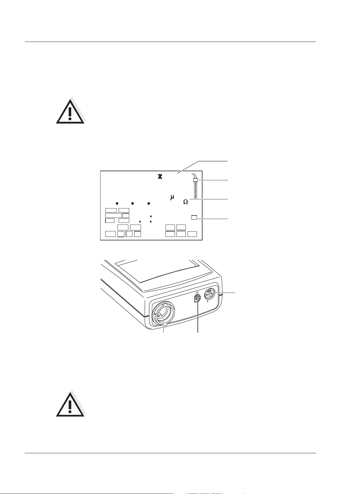
Display and jack field
Status display
indicator
TDS
S
8
1
Time
Day.Month No.
Year
Tref25
LoBat
nLF
Baud
Ident
8.
Tref20
Lin
8
8
Cal
OUpH
8
AutoCal DIN
AutoCal TEC
Sal
mV/pH
%
m
mbar
1/
°
8
Auto
ARng
mg/l
S/
M
cm
°
%
C
F
Store
AR
cm
Sal
K
/
cm
TP
RCL
Sensor symbol
Measured value
display
Function and
Temperature display
Jack field
3
12
1 Conductivity measuring cell
2 Plug-in power supply
3 RS232 interface or analog output/recorder
Warning
Only connect measuring cells to the measuring instrument that do not return
any unallowed voltages or currents (> SELV and > current circuit with current
limiting).
Almost all measuring cells fulfill these conditions.
4

BYKLC3 Mains power
Mains power
You can either operate the measuring instrument with batteries or with the
plug-in power supply. The plug-in power supply provides the measuring instrument with low voltage (7.5 V ... 12 V DC). This saves the batteries.
Warning
The line voltage at the operating site must lie within the input voltage range
of the original plug-in power supply (see T
Warning
Only use original plug-in power supplies (see T
ECHNICAL DATA).
ECHNICAL DATA).
2
3
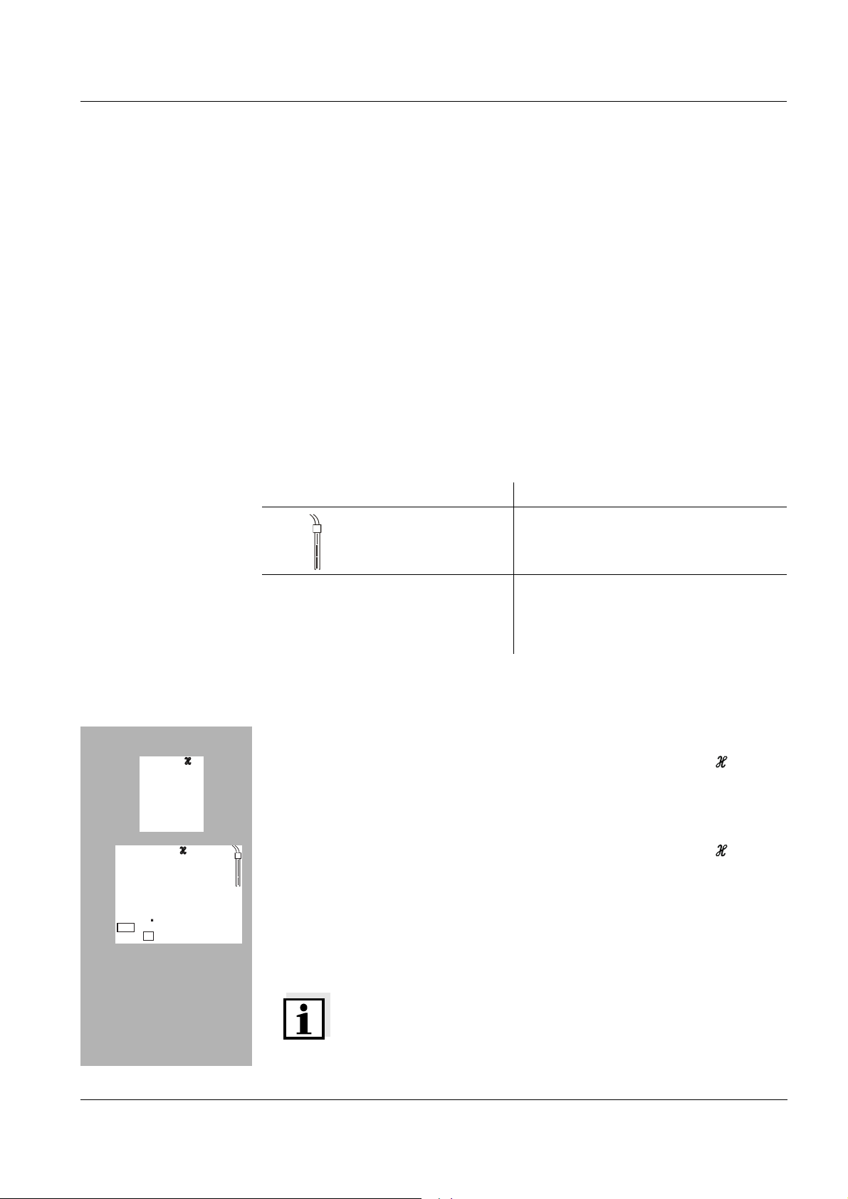
1
! Plug the jack (1) into the socket (2) of the measuring instrument.
! Connect the original plug-in power supply (3) to an easily accessible
mains socket.
Switching on the measuring instrument
! Press the <> key.
Display test appears briefly on the display.
After this, the measuring instrument automatically switches to the measuring mode. The display shows the relevant measured value.
5

Measuring BYK LC 3
Measuring
Overview of the measuring modes:
Salinity
Conductivity
µS/cm
Specific
resistance
McmΩ
depending on
the instrument setting
Special functions:
<M>
<M>
SAL
<M>
Total dis-
solved solids
(TDS) mg/l
AutoRead
(drift control)
AutoRange
measuring range
selection
Temperature
measurement
Factor for
dry filtrate residue
Temperature
compensation
The AutoRead function checks the stability of the measurement signal (except for the measurement of the ORP voltage). Activate AutoRead with
<AR>. Press <RUN/ENTER> to start the AutoRead measurement. During
the AutoRead measurement, AR flashes on the display until a stable measured value is reached. This can be terminated at any time taking over the
current measured value with <RUN/ENTER>.
There are several measuring ranges available for conductivity measurements. If a measuring range is exceeded, AutoRange causes the measuring
instrument to change automatically to the next measuring range. When the
AutoRange function is switched on, ARng appears on the display.
The measuring instrument automatically measures the temperature of the
sample with the integrated temperature sensor of the conductivity measuring
cell (display TP). In measuring cells without temperature sensors, the temperature can be entered manually with <▲> <▼>.
The factor for determining the dry filtrate residue is freely selectable in the
range 0.40 to 1.00. TDS is also displayed in the measuring mode as well as
the measured value. The factor can be changed if necessary with <▲> <▼>.
You can select from the following settings:
! Nonlinear temperature compensation (nLF) according to EN 27 888
! Linear temperature compensation (Lin) with selectable coefficients of
0.001 ... 3.000 %
! No temperature compensation (- - - -)
Press <CAL> until tc appears to set the temperature compensation. Then,
confirm with <RUN/ENTER>. Select the required option with <CAL>.
If necessary, select the temperature coefficients with <▲> <▼>. Return to the
measuring mode with <M>.
6
/K

BYK LC 3 Determining/Setting the cell constants
Determining/Setting the cell constants
Procedure The cell constants are determined in the control standard, 0.01 mol/l KCl.
Calibration
evaluation
You can determine the cell constants of the conductivity measuring cells in
the range of 0.450 ... 0.500 cm
You can also set the cell constants manually in the ranges
! 0.090 ... 0.110 cm
! 0.250 ... 2.500 cm-1
or select the fixed cell constants 0.010 cm
After the calibration, the measuring instrument automatically evaluates the
current status of the calibration. The evaluation appears on the display.
Display Cell constant [cm
E3
Invalid calibration
-1
-1
or 0.800 ... 1.200 cm
-1
.
0.450 ... 0.500 cm
0.800 ... 1.200 cm
Outside the range
0.450 ... 0.500 cm
or
0.800 ... 1.200 cm
-1
.
-1
]
-1
-1
-1
-1
E
CL
A
C
4
07
Tref25
Cal
L
2
L
Procedure for determining the cell constants:
! Connect a conductivity measuring cell to the measuring instrument.
! Press the <CAL> key repeatedly until the CELL display appears.
! Then press the <RUN/ENTER> key.
! Press the <CAL> key repeatedly until the CAL appears. Depending
on the calibration status, the instrument displays:
cm
1/
– the current, calibrated cell constant (with sensor symbol on the
display) or
– the fixed cell constant 0.475 1/cm (without sensor symbol on the
display). In this case, the measurement parameters are initialized.
Note
At this point, the procedure can be terminated with <M>.
! Immerse the conductivity measuring cell in the control standard solution,
0.01 mol/l KCI.
7

Determining/Setting the cell constants BYK LC 3
! Press <RUN/ENTER>. The AutoRead measurement begins.
! If the measured value is stable, the instrument displays the determined
cell constants and the calibration evaluation. The measuring instrument
A
C
4
07
Tref25
Cal
E
CL
8
6
01
Tref25
nLF
6
L
3
0
L
4
1/
ARng
cm
1/
S/
cm
cm
automatically stores the cell constants.
! Switch to the measuring mode with <M>.
Procedure for manually setting the cell constant:
! Press the <CAL> key repeatedly until the CELL display appears.
! Then press the <RUN/ENTER> key.
! Press the <CAL> key until a measured value and a value for the cell con-
stant appears in the required setting range.
! Set the value of the cell constant with <▲> <▼>.
! Switch to the measuring mode with <M>.
E
CL
2
9
0
01
Tref25
nLF
5
L
0
ARng
-1
Procedure for selecting fixed cell constants 0.010 cm
! Press the <CAL> key repeatedly until the CELL display appears.
! Then press the <RUN/ENTER> key.
! Press the <CAL> key until a measured value and the cell constant
S/
cm
cm
1/
0.010 cm
! Switch to the measuring mode with <M>.
-1
appear.
:
8

BYKLC3 Saving data
Saving data
Saving data
manually
Saving data
automatically Int 1
Press the <STO> key in the measuring mode (display No. with the number of
the next free memory location). Then press <RUN/ENTER> and enter the ID
number with <▲> <▼>. Terminate the save with <RUN/ENTER>. The instrument changes to the measuring mode.
The portable measuring instrument BYK LC 3 has an internal data memory.
It can store up to 800 datasets. The save interval (Int 1) determines the chronological interval between automatic save processes.
To set up the save interval, press <STO> while pressing the <RUN/ENTER>
key (display Int 1) and set the interval with <▲> <▼>key . Then, press
<RUN/ENTER> and enter the ID number with <▲> <▼>. Change to the last
active measuring mode with <RUN/ENTER>. The automatic save is switched
on (display Auto Store).
Outputting the data memory
You can output the data memory with the <RCL> key. By repeatedly pressing the <RCL> key, you reach the following functions:
StO dISP Output stored data on the display
StO SEr Output stored data via the serial interface
Transmitting data
manually
Transmitting data
automatically Int 2
CAL dISP Output calibration data on the display
CAL SEr Output calibration data via the serial interface
Start the output with <RUN/ENTER>.
Transmitting data
Press the <RUN/ENTER> key in the measuring mode.
This manually triggers a data transmission of the current measured value to
the serial interface at any time - independently of the selected intervals.
The interval to the data transmission (Int 2) determines the chronological interval between automatic data transmissions. After the selected interval expires, the current data record is transmitted to the interface. To set up the
transmission interval, press <RCL> while holding down the <RUN/ENTER>
key (display Int 2). Then, set the interval with <▲> <▼>.
9

Configuring BYK LC 3
Configuring
Note
You can leave the configuration menu at any time with <M>. The parameters
already changed are stored.
Procedure for configuring (factory settings appear in bold typeface):
! Switch off the measuring instrument.
! While pressing the <M> key, press <>.
1
Time
Baud
40
T
n
d
1
8
3
8
! Select the required Baud rate with <▲> <▼>.
0
Selection: 1200, 2400, 4800, 9600 Baud.
! Then press the <RUN/ENTER> key.
! Set the required calibration interval with <▲> <▼>.
Selection: 1... 180... 999 d.
! Then press the <RUN/ENTER> key.
0
A
C
Day.Month
t
Tref25
o
r
n
S
Y
E
ARng
2
5
S/
cm
d
n
4
9
00
! Switch the automatic measuring range selection AutoRange on/off with
<▲> <▼>.
Selection: YES (On), no (Off).
! Then press the <RUN/ENTER> key.
! Switchover the reference temperature of the conductivity with <▲> <▼>.
Selection: 25 °C (Tref25) and 20 °C (Tref20).
! Then press the <RUN/ENTER> key.
! Switch the units of the conductivity display on/off with <▲> <▼>.
Selection: S/cm, MΩ
! Then press the <RUN/ENTER> key.
! Select the date and time step-by-step with <▲> <▼>. In between, press
the <RUN/ENTER> key each time.
! When the last <RUN/ENTER> key has been pressed, the instrument
changes to the last active measuring mode.
⋅cm.
10

BYK LC 3 Resetting to default settings
Resetting to default settings
You can reset the measurement parameters and the configuration to the delivery status separately from one another (initialization).
Measurement
parameters
Configuration
parameters
The following measurement parameters can be reset to the delivery status:
Conductivity ( InI)
Measuring mode
AutoRange, automatic switchover
of the measurement range
Cell constant 0.475 cm
Temperature compensation nLF
Temperature coefficient of the linear temperature compensation
TDS factor 1.00
The following configuration parameters (InI) can be reset to the delivery status:
Baud rate 4800
Interval 1
(automatically saved) OFF
Interval 2
(for data transmission) OFF
On (YES)
0.475 cm
0.100 cm
2.000 %/K
-1
(calibrated)
-1
(manual range I)
-1
(manual range II)
I
n
I
n
o
Reset procedure:
! To switch it off, press <CAL><t> while pressing the <RUN/ENTER> key.
! To reset the measurement parameters with <▲> <▼>, select YES and
confirm with <RUN/ENTER>, or
! Continue to the configuration parameters (InI) without resetting with the
<RUN/ENTER> key.
! After the configuration parameters, InI changes the instrument to the last
active measurement mode.
11

Technical data BYK LC 3
Technical data
Dimensions
and weight
Mechanical
structure
Electrical
safety
Test certificates
Ambient
conditions
Length [mm] 172
Width [mm] 80
Height [mm] 37
Weight [kg] approx. 0.3
Type of protection IP 66
Protective class III
cETLus, CE
Storage - 25 °C ... + 65 °C
Operation -10 °C ... + 55 °C
Climatic class 2
Measuring ranges
[µS/cm]
0.000 ... 1.999
(only for cell constant = 0.090 ... 0.110 cm
0.00 ... 19.99
(only at a cell const. = 0.010 cm
cell const. = 0.090 ... 0.110 cm
-1
-1
and
)
0.0 ... 199.9
0 ... 1999
[mS/cm]
0.00 ... 19.99
0.0 ... 199.9
0 ... 500
Spec. resistance
[MΩ*cm]
0.000 ... 1.999
0.00 ... 19.99
0.0 ... 199.9
0 ... 1999
SAL 0.0 ... 70.0 according to the IOT table
TDS [mg/l] 0 ... 1999
Factor can be set to between 0.40 ... 1.00
T [°C] − 5.0 ... + 105.0
-1
)
12

BYKLC3 Technical data
Accuracy
(
± 1 digit)
Nonlinear compensation
Accuracy Sample temperature
± 0.5 % 0 °C ... 35 °C
according to EN 27 888;
± 0.5 % 35 °C ... 50 °C
extendednLF function
Linear compensation
Accuracy Sample temperature
± 0.5 % 10 °C ... 75 °C
(The accuracy percentage always refers to
the measured value.)
SAL Range 0.0 ... 42.0
Accuracy Sample temperature
± 0.1 5 °C ... 25 °C
± 0.2 25 °C ... 30 °C
TDS [mg/l] 1
T [°C] NTC 30:
Accuracy ± 0.1
Cell constant,
calibrating
Procedure for
setting the cell
constant:
Reference
temperature
Temperature input
PT 1000:
Accuracy Operating temperature
± 0.5 0 °C ... 15 °C
± 0.1 15 °C ... 35 °C
± 1 35 °C ... 55 °C
C [cm-1] 0.450 ... 0.500
0.800 ... 1.200
C [cm-1] 0.010 fixed
0.090 ... 0.110
0.250 ... 2.500
Tref Can be set to 20 °C or 25 °C
Manually [°C] -5 ... +100
13

Technical data BYK LC 3
Analog output Automatic switchover when the recorder is connected AK 323.
Output signal 0 ... 1.999 V for range
0 ... 1999 digits
Accuracy ± 0.5 % of display value
Internal resistance < 5 Ohm (current limited to max. 0.2 mA out-
put current)
Serial interface Automatic switchover when a PC or a printer is connected via the cable, AK
340/B or AK 325/S.
Type RS232, data output
Baud rate Can be set to 1200, 2400, 4800, 9600 Baud
Data bits 8
Stop bit 2
Power supply
Guidelines
and norms used
Parity None
Handshake RTS/CTS + Xon/Xoff
Cable length Max. 15 m
Batteries 4 x 1.5 V alkali-manganese batteries, Type AA
Operational life approx. 3000 operating hours
Mains The following applies to all plug-in power sup-
plies: Connection max. Overvoltage category II
Plug-in power supply unit
(Euro, US , UK, Australian plug)
FRIWO FW7555M/09, 15.1432
Friwo Part. No. 1822089
Input: 100 ... 240 V ~ / 50 ... 60 Hz / 400 mA
Output: 9 V = / 1,5 A
EMC EG guideline 89/336/EWG
EN 61326 A1:1998
EN 61000-3-2 A14:2000
EN 61000-3-3:1995
FCC Class A
14
Instrument safety EG guideline 73/23/EWG
EN 61010-1 A2:1995
Climatic class VDI/VDE 3540
Type of protection EN 60529:1991

BYKLC3 Scope of delivery
FCC Class A Equipment Statement
Note: This equipment has been tested and found to comply with the
limits for a Class A digital device, pursuant to Part 15 of the FCC Rules.
These limits are designed to provide reasonable protection against
harmful interference when the equipment is operated in a commercial
environment. This equipment generates, uses, and can radiate radio
frequency energy and, if not installed and used in accordance with the
instruction manual, may cause harmful interference to radio
communications. Operation of this equipment in a residential area is
likely to cause harmful interference in which case the user will be
required to correct the interference at his own expense.
Scope of delivery
! BYK LC 3 (cat. no.: 1745)
! Conductivity measuring cell TetraCon (cat. no.: 1741)
! Conductivity standard (cat. no.: 1747)
! Software MultiLab pilot (cat. no.: 1742)
! Adapter ADA USB/Ser
! Plug-in power supply, optional
! Operating manual and short operating manual
! CD-ROM
! 4 batteries, 1.5 V Mignon type AA (in the instrument)
15

Scope of delivery BYK LC 3
16

BYKLC3 Inhaltsverzeichnis
BYK LC 3 - Inhaltsverzeichnis
Sicherheit . . . . . . . . . . . . . . . . . . . . . . . . . . . . . . . . . . . . . . . . 18
Display und Buchsenfeld . . . . . . . . . . . . . . . . . . . . . . . . . . . . 18
Netzbetrieb . . . . . . . . . . . . . . . . . . . . . . . . . . . . . . . . . . . . . . . 19
Messgerät einschalten . . . . . . . . . . . . . . . . . . . . . . . . . . . . . . 19
Messen. . . . . . . . . . . . . . . . . . . . . . . . . . . . . . . . . . . . . . . . . . 20
Zellenkonstante bestimmen/einstellen . . . . . . . . . . . . . . . . . . 21
Speichern . . . . . . . . . . . . . . . . . . . . . . . . . . . . . . . . . . . . . . . . 23
Datenspeicher ausgeben . . . . . . . . . . . . . . . . . . . . . . . . . . . . 23
Daten übertragen . . . . . . . . . . . . . . . . . . . . . . . . . . . . . . . . . . 23
Konfigurieren . . . . . . . . . . . . . . . . . . . . . . . . . . . . . . . . . . . . . 24
Rücksetzen (Reset) auf Grundeinstellungen . . . . . . . . . . . . . 25
Technische Daten . . . . . . . . . . . . . . . . . . . . . . . . . . . . . . . . . 26
Lieferumfang . . . . . . . . . . . . . . . . . . . . . . . . . . . . . . . . . . . . . 29
17

Sicherheit BYK LC 3
Sicherheit
Sicherheits-
hinweise
Display
In den einzelnen Kapiteln dieser Bedienungsanleitung weisen Sicherheitshinweise wie der folgende auf Gefahren hin:
Achtung
kennzeichnet Hinweise, die genau beachtet werden müssen, um mögliche
leichte Verletzungen oder Schäden am Gerät oder der Umwelt zu vermeiden.
Display und Buchsenfeld
Statusanzeige
TDS
S
8
1
Time
Day.Month No.
Year
Tref25
LoBat
nLF
Baud
Ident
8.
Tref20
Lin
8
8
Cal
OUpH
8
AutoCal DIN
AutoCal TEC
Sal
mV/pH
%
m
mbar
1/
°
8
Auto
ARng
mg/l
S/
M
cm
°
%
C
F
Store
AR
cm
Sal
K
/
cm
TP
RCL
Sensorsymbol
Messwertanzeige
Funktions- und
Temperaturanzeige
Buchsenfeld
3
12
1 Leitfähigkeitsmesszelle
2 Steckernetzgerät
3 RS232 Schnittstelle bzw. Analogausgang/Schreiber
Achtung
Schließen Sie an das Messgerät nur Messzellen an, die keine unzulässigen
Spannungen oder Ströme (> SELV und > Stromkreis mit Strombegrenzung)
einspeisen können.
Nahezu alle Messzellen erfüllen diese Bedingungen.
18

BYKLC3 Netzbetrieb
Netzbetrieb
Sie können das Messgerät wahlweise mit Batterien oder mit dem Steckernetzgerät betreiben. Das Steckernetzgerät versorgt das Messgerät mit Klein-
spannung (7,5 V ... 12 V DC). Die Batterien werden dabei geschont.
Achtung
Die Netzspannung am Einsatzort muss innerhalb des Eingangs-Spannungsbereichs des Original-Steckernetzgeräts liegen (siehe T
Achtung
Verwenden Sie nur Original-Steckernetzgeräte (siehe T
2
ECHNISCHE DATEN).
ECHNISCHE DATEN).
3
1
! Stecker (1) in die Buchse (2) des Messgeräts stecken.
! Original Steckernetzgerät (3) an eine leicht zugängliche Steckdose an-
schließen
Messgerät einschalten
! Taste <> drücken.
Im Display erscheint kurz der Displaytest.
Das Messgerät schaltet danach automatisch in den Messmodus. Das
Display zeigt den zugehörigen Messwert an.
19

Messen BYK LC 3
Messen
Überblick über die Messmodi:
Salinität
Leitfähigkeit
µS/cm
Spezifischer
Widerstand
McmΩ
je nach Geräte-
einstellung
Spezialfunktionen:
<M>
<M>
SAL
<M>
Filtrattrocken-
rückstand TDS
mg/l
AutoRead
(Driftkontrolle)
Messbereichswahl
AutoRange
Temperatur-
messung
Faktor für
Filtrattrocken-
rückstand
Temperatur-
kompensation
Die Funktion AutoRead prüft die Stabilität des Messsignals. AutoRead mit
<AR> aktivieren. Der aktuelle Messwert wird eingefroren. Daher kann die Taste <AR> auch als "Hold-Funktion" zum Einfrieren von Messwerten verwendet werden. Zum Starten der AutoRead-Messung <RUN/ENTER> drükken.
Während der AutoRead-Messung blinkt die Anzeige AR, bis ein stabiler
Messwert vorliegt. Ein Abbruch mit Übernahme des aktuellen Messwerts ist
jederzeit mit <RUN/ENTER> möglich.
Es stehen für Leitfähigkeitsmessungen mehrere Messbereiche zur Verfü-
gung. AutoRange bewirkt, dass das Messgerät bei Überschreiten eines
Messbereichs automatisch in den nächsten Messbereich wechselt. Bei eingeschalteter Funktion AutoRange erscheint die Anzeige ARng.
Das Messgerät misst die Temperatur der Messlösung automatisch mit dem
integrierten Temperaturmessfühler der Leitfähigkeitsmesszelle (Anzeige
TP). Bei Messzellen ohne Temperaturmessfühler kann die Temperatur mit
<▲> <▼> manuell eingegeben werden.
Der Faktor zur Bestimmung des Filtrattrockenrückstands ist im Bereich 0,40
bis 1,00 frei einstellbar. Er wird im Messmodus TDS zusätzlich zum Messwert angezeigt. Faktor gegebenfalls mit <▲> <▼> ändern.
Sie können unter folgenden Einstellungen wählen:
! Nichtlineare Temperaturkompensation (nLF) nach EN 27 888
20
! Lineare Temperaturkompensation (Lin) mit einstellbarem Koeffizienten
von 0,001 ... 3,000 %
! Keine Temperaturkompensation (- - - -)
Zum Einstellen der Temperaturkompensation <CAL> drücken, bis tc erscheint. Anschließend mit <RUN/ENTER> bestätigen. Mit <CAL> gewünschte Option wählen. Gegebenenfalls Temperaturkoeffizienten mit
<▲> <▼> einstellen. Mit <M> zurück zum Messmodus.
/K

BYK LC 3 Zellenkonstante bestimmen/einstellen
Zellenkonstante bestimmen/einstellen
Verfahren Die Bestimmung der Zellenkonstante erfolgt im Kontrollstandard 0,01 mol/l
KCl.
Kalibrier-
bewertung
Sie können die Zellenkonstante der Leitfähigkeitsmesszelle im Bereich 0,450
... 0,500 cm
Sie können die Zellenkonstante außerdem in den Bereichen
! 0,090 ... 0,110 cm
! 0,250 ... 2,500 cm-1
manuell einstellen oder die feste Zellenkonstante 0,010 cm
Nach dem Kalibrieren bewertet das Messgerät automatisch den aktuellen
Zustand der Kalibrierung. Die Bewertung erscheint im Display.
Anzeige Zellenkonstante [cm
Unzulässige Kalibrierung
E3
-1
bzw. 0,800 ... 1,200 cm
-1
-1
bestimmen.
-1
0,450 ... 0,500 cm
0,800 ... 1,200 cm
außerhalb des Bereichs
0,450 ... 0,500 cm
oder
0,800 ... 1,200 cm
-1
-1
-1
-1
wählen.
-1
]
E
CL
A
C
4
07
Tref25
Cal
L
2
L
Ablauf Zellenkonstante bestimmen:
! Leitfähigkeitsmesszelle an das Messgerät anschließen.
! Taste <CAL> drücken, bis die Anzeige CELL erscheint.
! Anschließend Taste <RUN/ENTER> drücken.
! Taste <CAL> drücken, bis die Anzeige CAL erscheint. Je nach Kali-
brierzustand wird angezeigt:
cm
1/
– die aktuelle, kalibrierte Zellenkonstante (mit Sensorymbol im
Display) oder
– die feste Zellenkonstante 0,475 1/cm (ohne Sensorsymbol im
Display). In diesem Fall sind die Messparameter initialisiert.
Hinweis
An dieser Stelle kann mit <M> abgebrochen werden.
21

Zellenkonstante bestimmen/einstellen BYK LC 3
! Leitfähigkeitsmesszelle in die Kontrollstandardlösung 0,01 mol/l KCI
tauchen.
! <RUN/ENTER> drücken. Die AutoRead-Messung beginnt.
! Wenn der Messwert stabil ist, zeigt das Gerät die ermittelte Zellenkon-
stante und die Kalibrierbewertung an. Das Messgerät speichert die Zel-
A
C
4
07
Tref25
Cal
E
CL
L
3
L
cm
1/
lenkonstante automatisch.
! Mit <M> in den Messmodus wechseln.
Ablauf Zellenkonstante manuell einstellen:
! Taste <CAL> drücken, bis die Anzeige CELL erscheint.
! Anschließend Taste <RUN/ENTER> drücken.
8
6
6
01
Tref25
nLF
E
CL
2
9
0
01
Tref25
nLF
0
5
L
4
0
ARng
ARng
! Taste <CAL> drücken, bis ein Messwert und ein Wert für die Zellenkon-
S/
cm
cm
1/
S/
cm
cm
1/
stante im gewünschten Einstellbereich erscheint.
! Mit <▲> <▼> den Wert der Zellenkonstante einstellen.
! Mit <M> in den Messmodus wechseln.
-1
Ablauf feste Zellenkonstante 0,010 cm
! Taste <CAL> drücken, bis die Anzeige CELL erscheint.
! Anschließend Taste <RUN/ENTER> drücken.
! Taste <CAL> drücken, bis ein Messwert und die Zellenkonstante
0,010 cm
! Mit <M> in den Messmodus wechseln.
-1
erscheint.
wählen:
22

BYKLC3 Speichern
Speichern
Daten manuell
speichern
Daten automatisch
Speichern Int 1
Im Messmodus Taste <STO> drücken (Anzeige No. mit der Nummer des
nächsten freien Speicherplatzes). Anschließend <RUN/ENTER> drücken
und Identnummer mit <▲> <▼> eingeben. Speichern mit <RUN/ENTER>
abschließen. Das Gerät wechselt in den Messmodus.
Das Taschenmessgerät BYK LC 3 verfügt über einen internen Datenspeicher. Darin können bis zu 800 Datensätze abgespeichert werden. Das Speicherintervall (Int 1) bestimmt den zeitlichen Abstand zwischen
automatischen Speichervorgängen.
Zum Einstelllen des Speicherintervalls <STO> bei gedrückter Taste <RUN/
ENTER> drücken (Anzeige Int 1) und Intervall mit <▲> <▼> einstellen. An-
schließend <RUN/ENTER> drücken und Identnummer mit <▲> <▼> eingeben. Mit <RUN/ENTER> in den zuletzt aktiven Messmodus wechseln. Das
automatische Speichern ist eingeschaltet (Anzeige Auto Store).
Datenspeicher ausgeben
Mit der Taste <RCL> können Sie den Datenspeicher ausgeben. Durch mehrmaliges Drücken der Taste <RCL> gelangen Sie zu folgenden Funktionen:
StO dISP gespeicherte Daten auf Display ausgeben
Daten manuell
übertragen
Daten automatisch
übertragen Int 2
StO SEr gespeicherte Daten auf serielle Schnittstelle ausgeben
CAL dISP Kalibrierdaten auf Display ausgeben
CAL SEr Kalibrierdaten auf serielle Schnittstelle ausgeben
Ausgabe mit <RUN/ENTER> starten.
Daten übertragen
Im Messmodus Taste <RUN/ENTER> drücken.
Damit lösen Sie jederzeit manuell eine Datenübertragung des aktuellen
Messwertes zur seriellen Schnittstelle aus - unabhängig von den eingestellten Intervallen.
Das Intervall zur Datenübertragung (Int 2) bestimmt den zeitlichen Abstand
zwischen automatischen Datenübertragungen. Nach Ablauf des eingestellten Intervalls wird der aktuelle Datensatz an die Schnittstelle übertragen.
Zum Einstelllen des Übertragungsintervalls <RCL> bei gedrückter Taste
<RUN/ENTER> drücken (Anzeige Int 2). Anschließend Intervall mit <▲>
<▼> einstellen.
23

Konfigurieren BYK LC 3
Konfigurieren
Hinweis
Sie können das Konfigurationsmenü jederzeit mit <M> verlassen. Die bereits
geänderten Parameter sind gespeichert.
Ablauf Konfigurieren (Werkseinstellungen sind fett gekennzeichnet):
! Messgerät ausschalten.
! Bei gedrückter Taste <M> Taste <> drücken.
1
Time
Baud
40
T
n
d
1
8
3
8
! Gewünschte Baudrate mit <▲> <▼> einstellen.
0
Auswahl: 1200, 2400, 4800, 9600 Baud.
! Anschließend Taste <RUN/ENTER> drücken.
! Gewünschtes Kalibrierintervall mit <▲> <▼> einstellen.
Auswahl: 1... 180... 999 d.
! Anschließend Taste <RUN/ENTER> drücken.
0
A
C
Day.Month
t
Tref25
o
r
n
S
Y
E
ARng
2
5
S/
cm
d
n
4
9
00
! Automatische Messbereichswahl AutoRange mit <▲> <▼> aus/ein-
schalten.
Auswahl: YES (ein), no (aus).
! Anschließend Taste <RUN/ENTER> drücken.
! Referenztemperatur der Leitfähigkeit mit <▲> <▼> umschalten.
Auswahl: 25 °C (Tref25) und 20 °C (Tref20).
! Anschließend Taste <RUN/ENTER> drücken.
! Einheit der Leitfähigkeitsanzeige mit <▲> <▼> aus/einschalten.
Auswahl: S/cm, MΩ
! Anschließend Taste <RUN/ENTER> drücken.
! Datum und Uhrzeit Schritt für Schritt mit <▲> <▼> einstellen. Dazwi-
schen jeweils Taste <RUN/ENTER> drücken.
! Nach dem letzten Druck auf die Taste <RUN/ENTER> wechselt das Ge-
rät in den zuletzt aktiven Messmodus.
⋅cm.
24

BYKLC3 Rücksetzen (Reset) auf Grundeinstellungen
Rücksetzen (Reset) auf Grundeinstellungen
Sie können die Messparameter und die Konfiguration getrennt voneinander
auf den Lieferzustand rücksetzen (initialisieren).
Messparameter Die folgenden Messparameter lassen sich auf den Auslieferzustand rückset-
zen:
Leitfähigkeit ( InI)
Messmodus
Konfigurations-
parameter
Automatische Messbereichsumschaltung AutoRange
Zellenkonstante 0,475 cm
Temperaturkompensation nLF
Temperaturkoeffizient der linearen
Temperaturkompensation
TDS-Faktor 1,00
Die folgenden Konfigurationsparameter (InI) lassen sich auf den Auslieferzustand rücksetzen:
Baudrate 4800
Intervall 1
(automatisches Speichern) OFF
Intervall 2
(für Datenübertragung) OFF
Ablauf Rücksetzen:
Ein (YES)
0,475 cm
0,100 cm
2,000 %/K
-1
(kalibriert)
-1
(manueller Bereich I)
-1
(manueller Bereich II)
I
n
I
n
o
! Bei gedrückter Taste <RUN/ENTER> Taste <CAL> drücken.
! Zum Rücksetzen der Messparameter mit <▲> <▼> YES wählen und mit
<RUN/ENTER> bestätigen, oder
! mit Taste <RUN/ENTER> ohne Rücksetzen weiter zu den Konfigurati-
onsparametern (InI).
! Nach den Konfigurationsparametern InI wechselt das Gerät in den zu-
letzt aktiven Messmodus.
25

Technische Daten BYK LC 3
Technische Daten
Abmessungen
und Gewicht
Mechanischer
Aufbau
Elektrische
Sicherheit
Prüfzeichen
Umgebungs-
bedingungen
Länge [mm] 172
Breite [mm] 80
Höhe [mm] 37
Gewicht [kg] ca. 0,3
Schutzart IP 66
Schutzklasse III
cETLus, CE
Lagerung - 25 °C ... + 65 °C
Betrieb -10 °C ... + 55 °C
Klimaklasse 2
Messbereiche
[µS/cm]
0,000 ... 1.999
(nur bei Zellenkonst. = 0,090 ... 0,110 cm
0,00 ... 19,99
(nur bei Zellenkonst. = 0,010 cm
Zellenkonst. = 0,090 ... 0,110 cm
0,0 ... 199,9
0 ... 1999
[mS/cm]
0,00 ... 19,99
0,0 ... 199,9
0 ... 500
spez. Widerstand
[MΩ*cm]
0,000 ... 1,999
0,00 ... 19,99
0,0 ... 199,9
0 ... 1999
SAL 0,0 ... 70,0 nach IOT-Tabelle
TDS [mg/l] 0 ... 1999
Faktor einstellbar zwischen 0,40 ... 1,00
T [°C] − 5,0 ... + 105,0
-1
-1
und
)
-1
)
26

BYKLC3 Technische Daten
Genauigkeit
(± 1 digit)
Nichtlineare Kompensation :
Genauigkeit Messguttemperatur
± 0,5 % 0 °C ... 35 °C
nach EN 27 888;
± 0,5 % 35 °C ... 50 °C
erweiterte nLF-Funktion
Lineare Kompensation :
Genauigkeit Messguttemperatur
± 0,5 % 10 °C ... 75 °C
(der Prozentwert der Genauigkeit bezieht
sich jeweils auf den Messwert!)
SAL Bereich 0,0 ... 42,0
Genauigkeit Messguttemperatur
± 0,1 5 °C ... 25 °C
± 0,2 25 °C ... 30 °C
TDS [mg/l] 1
T [°C] NTC 30:
Genauigkeit ± 0,1
Zellenkonstante
kalibrieren
Zellenkonstante
einstellen
Referenz-
temperatur
Temperatureinabe
PT 1000:
Genauigkeit Betriebstemperatur
± 0,5 0 °C ... 15 °C
± 0,1 15 °C ... 35 °C
± 1 35 °C ... 55 °C
C [cm-1] 0,450 ... 0,500
0,800 ... 1,200
C [cm-1] 0,010 fest
0,090 ... 0,110
0,250 ... 2,500
Tref einstellbar 20 °C oder 25 °C
Manuell [°C] -5 ... +100
27

Technische Daten BYK LC 3
Analogausgang Automatische Umschaltung bei Anschluss des Schreiberkabels AK 323.
Ausgangssignal 0 ... 1,999 V für Bereichspanne
0 ... 1999 Digit
Genauigkeit ± 0,5 % vom Anzeigewert
Innenwiderstand < 5 Ohm (Strombegrenzung auf max.
0,2 mA Ausgangsstrom)
Serielle
Schnittstelle
Automatische Umschaltung bei Anschluss eines PCs oder eines Druckers
über das Kabel AK 340/B oder AK 325/S.
Typ RS232, Datenausgabe
Baudrate einstellbar
1200, 2400, 4800, 9600 Baud
Datenbits 8
Stoppbit 2
Parität keine (None)
Handshake RTS/CTS+Xon/Xoff
Kabellänge max. 15 m
28

BYKLC3 Lieferumfang
Energie-
versorgung
Batterien 4 x 1,5 V Alkali-Mangan-Batterien Typ AA
Laufzeit ca. 3000 Betriebsstunden
Netz Für alle Steckernetzgeräte gilt:
Anschluss max. Überspannungskategorie II
Steckernetzgerät mit
Euro-, US-, UK- und Austr.-Stecker:
FRIWO FW7555M/09, 15.1432
Friwo Part. No. 1822089
Input: 100 ... 240 V ~ /
50 ... 60 Hz / 400 mA
Output: 9 V = / 1,5 A
Angewendete
Richtlinien und
Normen
EMV EG-Richtlinie 89/336/EWG
EN 61326 A1:1998
EN 61000-3-2 A14:2000
EN 61000-3-3:1995
FCC Class A
Gerätesicherheit EG-Richtlinie 73/23/EWG
EN 61010-1 A2:1995
Klimaklasse VDI/VDE 3540
Schutzart EN 60529:1991
Lieferumfang
! BYK LC 3 (Kat.-Nr.: 1745)
! Leitfähigkeitsmesszelle TetraCon (Kat.-Nr.: 1741)
! Leitfähigkeitsstandard (Kat.-Nr.: 1747)
! Software MultiLab pilot (Kat.-Nr.: 1742)
! Adapter ADA USB/Ser
! Steckernetzgerät optional
! Bedienungsanleitung und Kurzanleitung
! CD-ROM
! 4 Batterien 1,5 V Mignon Typ AA (im Gerät)
29

Lieferumfang BYK LC 3
30

BYKLC3 Sommaire
BYK LC 3 - Sommaire
Sécurité . . . . . . . . . . . . . . . . . . . . . . . . . . . . . . . . . . . . . . . . . 32
Affichage et emplacement de la douille . . . . . . . . . . . . . . . . . 32
Alimentation du réseau. . . . . . . . . . . . . . . . . . . . . . . . . . . . . . 33
Allumer l'appareil de mesure . . . . . . . . . . . . . . . . . . . . . . . . . 33
Mesure . . . . . . . . . . . . . . . . . . . . . . . . . . . . . . . . . . . . . . . . . . 34
Déterminer/régler la constante de cellule . . . . . . . . . . . . . . . . 35
Enregistrement . . . . . . . . . . . . . . . . . . . . . . . . . . . . . . . . . . . . 37
Écrire en sortie la mémoire de données. . . . . . . . . . . . . . . . . 37
Transmission de données . . . . . . . . . . . . . . . . . . . . . . . . . . . 37
Configuration . . . . . . . . . . . . . . . . . . . . . . . . . . . . . . . . . . . . . 38
Remettre (Reset) à l'état initial . . . . . . . . . . . . . . . . . . . . . . . . 39
Données techniques. . . . . . . . . . . . . . . . . . . . . . . . . . . . . . . . 40
Fournitures à la livraison . . . . . . . . . . . . . . . . . . . . . . . . . . . . 43
31
Sécurité BYK LC 3
Sécurité
Indications de
sécurité
Affichage
Dans les chapitres suivants de ce mode d'emploi, des informations de sécurité comme celle qui suit visent sur des dangers possibles:
Attention
signale les indications à respecter précisément pour éviter des blessures légères, des endommagement de l'appareil ou de l'environnement.
Affichage et emplacement de la douille
Affichage de l'état
TDS
S
8
1
Time
Day.Month No.
Year
Tref25
LoBat
nLF
Baud
Ident
8.
Tref20
Lin
8
8
Cal
OUpH
8
AutoCal DIN
AutoCal TEC
Sal
mV/pH
%
m
mbar
1/
°
8
Auto
ARng
mg/l
S/
M
cm
°
%
C
F
Store
AR
cm
Sal
K
/
cm
TP
RCL
Symbole de sonde
Affichage des valeurs
mesurées
Affichage fonction
et température
Emplacement de la
douille
3
12
1 Cellule de mesure de la conductivité
2 Transformateur d'alimentation
3 RS232 Interface ou sortie analogique/enregistreur
Attention
Ne raccordez à l'appareil de mesure que des cellules de mesure ne pouvant
pas être alimentées par des tensions ou courants nonautorisés (> SELV et
> circuit avec limitation de courant).
A peu près toutes les cellules de mesure remplissent ces conditions.
32

BYKLC3 Alimentation du réseau
Alimentation du réseau
Vous pouvez alimenter l'appareil de mesure ou avec des piles ou bien avec
un transformateur d'alimentation. Le transformateur d'alimentation assure
l'alimentation de l'appareil de mesure en très basse tension
(7,5 V ... 12 V DC). ce qui ménage les piles.
Attention
La tension du secteur du lieu d'utilisation doit se situer dans la plage de tension d'entrée du transformateur d'alimentation original (voir D
NIQUES).
Attention
Utilisez uniquement les transformateurs d'alimentation originaux (voir D
NÉES TECHNIQUES).
2
ONNÉES TECH-
ON-
3
1
! Brancher le connecteur (1) dans la douille (2) de l'appareil de mesure.
! Brancher le transformateur d'alimentation (3) sur une prise facilement ac-
cessible.
Allumer l'appareil de mesure
! Appuyer sur la touche >.
A l'écran s'affiche rapidement le test d'affichage.
Ensuite, l'appareil de mesure commute automatiquement sur le mode de
mesure. L'affichage indique la valeur mesurée.
33

Mesure BYK LC 3
Mesure
Résumé des modes de mesure:
Salinité
Conductivité
µS/cm
Résistance
spécific
McmΩ
selon le ajustement
d l’appareil
Fonctions spéciales:
<M>
<M>
SAL
<M>
Residu
d’évaporation
(TDS) mg/l
AutoRead
(Contrôle de
dérive)
Choix de la plage
de mesure
AutoRange
Mesure de
température
Facteur pour
résidu sec du
filtrat
Compensation
de température
La fonction AutoRead examine la stabilité du signal de mesure (sauf mesure
d'un potentiel Redox). Activer AutoRead avec <AR>. Pour mettre en route la
mesure AutoRead, appuyer sur <RUN/ENTER>. Pendant la mesure AutoRead, l'indication AR clignote jusqu'à ce qu'une valeur de mesure stable se
présente. L'interruption avec enregistrement de la valeur de mesure actuelle
est possible à tout moment en appuyant <RUN/ENTER>.
Il y a plusieurs plages de mesure pour les mesures de la conductivité. AutoRange assure que, en cas d'un dépassement d'une plage de mesure, l'appareil de mesure change automatiquement dans la plage de mesure suivante.
Si la fonction AutoRange est activée, il est affiché ARng.
L'appareil mesure automatiquement la température de la solution de mesure
à l'aide de la sonde de température intégrée de la cellule de mesure de la
conductivité (Indication affichée TP). Quand il s'agit de cellules de mesure
sans sonde de température, l'introduction de la température peut se faire de
manière manuelle avec <▲> <▼>.
Le facteur pour déterminer le résidu sec du filtrat peut se régler librement
dans la plage de 0,40 à 1,00. Il s'affiche au mode de mesure TDS en plus de
la valeur de mesure. Modifier le facteur au besoin avec <▲> <▼>.
Vous pouvez choisir entre les positionnements suivants:
! Compensation de température non linéaire (nLF) selon NE 27 888
34
! Compensation de température linéaire (Lin) aux coefficients réglables
de 0,001 ... 3,000 %
! Pas de compensation de température (- - - -)
Pour ajuster la compensation de température appuyer sur <CAL> jusqu'à ce
que tc s'affiche. Ensuite confirmer avec <RUN/ENTER>. Choisir l'option
souhaitée avec <CAL>. Éventuellement ajuster le coefficient de température
avec <▲> <▼>. Avec <M> retour au mode de mesure.
/K

BYKLC3 Déterminer/régler la constante de cellule
Déterminer/régler la constante de cellule
Procédure La détermination de la constante de cellule s'effectue au standard de contrô-
le 0,01 mol/l KCl.
Evaluation de
calibration
Vous pouvez déterminer la constante de cellule de la cellule de mesure de la
conductivité dans la plage 0,450 ... 0,500 cm
Vous pouvez également régler de façon manuelle la constante de cellule
dans les plages
! 0,090 ... 0,110 cm
! 0,250 ... 2,500 cm-1
ou choisir la constante de cellule fixe à 0,010 cm
Après la calibration, l'appareil de mesure évalue automatiquement l'état actuel de la calibration. L'évaluation apparaît à l'écran.
Indication Constante de cellule [cm
E3
Calibration incorrecte
-1
0,450 ... 0,500 cm
0,800 ... 1,200 cm
en dehors de
0,450 ... 0,500 cm
ou
0,800 ... 1,200 cm
-1
ou bien 0,800 ... 1,200 cm
-1
.
-1
]
-1
-1
-1
-1
-1
.
E
CL
A
C
4
07
Tref25
Cal
L
2
L
Déroulement de la détermination de la constante de cellule:
! Raccorder à l'appareil de mesure la cellule de mesure de la conductivité.
! Appuyer sur la touche <CAL> éventuellement plusieurs fois jusqu'à af-
fichage de l'indication CELL.
! Ensuite appuyer sur la touche <RUN/ENTER>.
! Appuyer sur la touche <CAL> plusieurs fois au besoin jusqu'à affichage
de l'indication CAL. Suivant l'état de calibration s'affiche:
cm
1/
– la constante de cellule actuelle et calibrée (avec le symbole de sonde
dans la fenêtre) ou bien
– la constante de cellule fixe 0,475 1/cm (sans symbole de sonde dans
la fenêtre). Dans ce cas, les paramètres de mesure sont initialisés.
Remarque
À ce moment, on peut arrêter avec <M>.
35

Déterminer/régler la constante de cellule BYK LC 3
! Immerger la cellule de mesure de la conductivité dans la solution de con-
trôle standard 0,01 mol/l KCI.
! Appuyer sur <RUN/ENTER>. La mesure AutoRead se met en marche.
! Lorsque la valeur mesurée est stable, l'appareil indique la valeur de la
constante de cellule déterminée, ainsi que l'évaluation de calibration.
A
C
4
07
Tref25
Cal
E
CL
L
3
L
cm
1/
L'appareil de mesure enregistre automatiquement la constante de cellule.
! Commuter sur le mode de mesure avec <M>.
Déroulement régler la constante de cellule manuellement
! Appuyer sur la touche <CAL> éventuellement plusieurs fois jusqu'à af-
fichage de l'indication CELL.
! Ensuite appuyer sur la touche <RUN/ENTER>.
8
6
6
01
Tref25
nLF
E
CL
2
9
0
01
Tref25
nLF
0
5
L
4
0
ARng
ARng
! Appuyer sur la touche <CAL> jusqu'à affichage d'une valeur mesurée et
S/
cm
cm
1/
S/
cm
cm
1/
d'une valeur de la constante de cellule dans la plage de réglage souhaitée.
! Régler la valeur de cellule en appuyant sur la touche <▲> <▼>.
! Commuter sur le mode de mesure avec <M>.
-1
Déroulement choisir la constante de cellule fixe à 0,010 cm
! Appuyer sur la touche <CAL> éventuellement plusieurs fois jusqu'à af-
fichage de l'indication CELL.
! Ensuite appuyer sur la touche <RUN/ENTER>.
! Appuyer sur la touche <CAL>c jusqu'à affichage d'une valeur mesurée et
de la constante de cellule 0,010 cm
! Commuter sur le mode de mesure avec <M>.
-1
.
.
36

BYKLC3 Enregistrement
Enregistrement
Enregistrement
manuel de
données
Enregistrement
automatique de
données Int 1
Appuyer sur la touche <STO> au mode de mesure (indication affichée No.
avec le numéro de la position de mémoire disponible). Ensuite appuyer sur
<RUN/ENTER> et entrer le numéro d'identification avec <▲> <▼>. Finir l'en-
registrement avec <RUN/ENTER>. L'appareil commute sur le mode de mesure.
L'appareil de mesure de poche BYK LC 3 dispose d'une mémoire de données interne. Il est possible d'y enregistrer jusqu'à 800 groupes de données.
L'intervalle d'enregistrement (Int 1) détermine l'intervalle temporel entre les
processus d'enregistrement automatiques.
Pour régler l'intervalle d'enregistrement appuyer sur <STO> et appuyer en
même temps sur la touche <RUN/ENTER> (indication affichée Int 1) et ajus-
ter l'intervalle avec <▲> <▼>. Ensuite appuyer sur <RUN/ENTER> et entrer
le numéro d'identification avec <▲> <▼>. Commuter avec <RUN/ENTER>
dans le mode de mesure actif ultérieurement. L'enregistrement automatique
est activé (indication affichée Auto Store).
Écrire en sortie la mémoire de données
Appuyer sur la touche <RCL> pour écrire en sortie la mémoire de données.
Vous arrivez à des fonctions indiquées ci-dessous en appuyant plusieurs fois
sur la touche <RCL>:
Transmission
manuelle de
données
Transmission de
données
automatiqueb Int 2
StO dISP écrire en sortie des données enregistrées dans la fenêtre affichage
StO SEr écrire en sortie des données enregistrées sur l'interface sérielle
CAL dISP écrire en sortie des données de calibration dans la fenêtre affichage
CAL SEr écrire en sortie des données de calibration sur l'interface sérielle
Déclencher l'écriture en sortie avec <RUN/ENTER>.
Transmission de données
Appuyer sur la touche <RUN/ENTER> au mode de mesure.
Ainsi vous déclenchez à tout moment manuellement une transmission de
données de la valeur mesurée actuelle vers l'interface sérielle - indépendamment des intervalles configurés.
L'intervalle pour la transmission de données (Int 2) détermine l'intervalle de
temps entre les transmissions de données automatiques. Après déroulement
de l'intervalle réglé, le groupe de données actuel est transmis à l'interface.
Pour régler l'intervalle de transmission appuyer sur <RCL> et en même
temps la touche <RUN/ENTER> (indication affichée Int 2). Ensuite, régler
l'intervalle avec <▲> <▼>.
37

Configuration BYK LC 3
Configuration
Remarque
Vous pouvez quitter le menu de configuration à tout moment en appuyant sur
<M>. Les paramètres déjà modifiés sont enregistrés.
Déroulement de la configuration (Les ajustements faits à l'usine sont indi-
qués en gras):
! Éteindre l'appareil de mesure.
! Appuyer sur la touche <M> et en même temps sur <>.
Baud
8
40
! Ensuite, régler baudrate désiré avec <▲> <▼>.
0
Au choix: 1200, 2400, 4800, 9600 Baud.
! Ensuite appuyer sur la touche <RUN/ENTER>.
! L'intervalle de calibration souhaité se règle avec <▲> <▼>.
Au choix: 1... 180... 999 d.
! Ensuite appuyer sur la touche <RUN/ENTER>.
1
Time
n
A
C
Day.Month
t
Tref25
o
T
3
1
d
8
r
n
Y
E
2
5
S/
d
n
9
00
0
! Activer/désactiver le choix de la plage de mesure automatique AutoRange
avec <▲> <▼>.
Au choix: YES (allumé), no (éteint).
! Ensuite appuyer sur la touche <RUN/ENTER>.
S
ARng
! Commuter la température de référence de la conductivité avec <▲> <▼>
Au choix: 25 °C (Tref25) et 20 °C (Tref20).
! Ensuite appuyer sur la touche <RUN/ENTER>.
! Allumer/éteindre l'unité d'affichage de la conductivité avec <▲> <▼>.
cm
4
Au choix: S/cm, MΩ
! Ensuite appuyer sur la touche <RUN/ENTER>.
! Ajuster la date et l'heure en pas à pas avec <▲> <▼>. Entre les pas, ap-
puyer sur la touche <RUN/ENTER>.
! Après avoir appuyé la dernière fois sur la touche <RUN/ENTER> l'ap-
pareil commute au mode de mesure actif ultérieurement.
⋅cm.
38

BYK LC 3 Remettre (Reset) à l'état initial
Remettre (Reset) à l'état initial
Vous pouvez remettre à l'état initial de livraison séparément les paramètres
de mesure et la configuration (initialiser).
Paramètres de
mesure
Paramètres de
configuration
Les paramètres de mesure suivants sont à remettre à l'état initial de livraison:
Conductivité ( InI)
Mode de mesure
Commutation de la plage de mesure
automatique AutoRange
Constante de cellule 0,475 cm
Compensation de température nLF
Coefficient de température de la
compensation de température
linéaire
Facteur TDS 1,00
Les paramètres de configuration suivants (InI) sont à remettre à l'état initial
de livraison:
Débit en bauds 4800
Intervalle 1
(enregistrement automatique) OFF
ALLUMÉ (YES)
-1
(calibré)
0,475 cm
0,100 cm
2,000 %/K
-1
(plage manuelle I)
-1
(plage manuelle II)
I
n
I
n
o
Intervalle 2
(pour transmission de données) OFF
Déroulement remise à l'état initial:
! Appuyer sur la touche <RUN/ENTER> et en même temps sur <CAL>.
! Si les paramètres de mesure sont à remettre à l'état initial choisir avec
<▲> <▼> YES et confirmer avec <RUN/ENTER>, ou,
! sans remettre, continuer avec la touche <RUN/ENTER> jusqu'aux pa-
ramètres de configuration (InI ).
! Après les paramètres de configuration InI l'appareil commute au mode de
mesure actif ultérieurement.
39

Données techniques BYK LC 3
Données techniques
Dimensions
et poids
Construction
mécanique
Sécurité
électrique
Marque de
contrôle
Conditions
de milieu
Longueur [mm] 172
Largeur [mm] 80
Hauteur [mm] 37
Poids [kg] env. 0,3
Manière de protection IP 66
Classe de protection III
cETLus, CE
Stockage - 25 °C ... + 65 °C
Fonctionnement -10 °C ... + 55 °C
Plages de mesure
Catégorie climatique 2
[µS/cm]
0,000 ... 1.999
(seulement pour constante de cellule) =
0,090 ... 0,110 cm
-1
)
0,00 ... 19,99
(seulement pour const. de cellule = 0,010 cm
const. de cellule = 0,090 ... 0,110 cm
0,0 ... 199,9
0 ... 1999
[mS/cm]
0,00 ... 19,99
0,0 ... 199,9
0 ... 500
Résistance spéc.
[MΩ*cm]
0,000 ... 1,999
0,00 ... 19,99
0,0 ... 199,9
0 ... 1999
SAL 0,0 ... 70,0 selon tableau IOT
-1
-1
)
et
40
TDS [mg/l] 0 ... 1999
Facteur réglable entre 0,40 ... 1,00

BYKLC3 Données techniques
Précision
(± 1 digit)
[µS/cm]
0,000 ... 1.999
(seulement pour constante de cellule) =
0,090 ... 0,110 cm
-1
)
0,00 ... 19,99
(seulement pour const. de cellule = 0,010 cm
const. de cellule = 0,090 ... 0,110 cm
0,0 ... 199,9
0 ... 1999
[mS/cm]
0,00 ... 19,99
0,0 ... 199,9
0 ... 500
Résistance spéc.
[MΩ*cm]
0,000 ... 1,999
0,00 ... 19,99
0,0 ... 199,9
0 ... 1999
T [°C] − 5,0 ... + 105,0
Compensation non linéaire :
Précision température de la solution à
mesurer
± 0,5 % 0 °C ... 35 °C
selon NE 27 888;
± 0,5 % 35 °C ... 50 °C
-1
-1
)
et
Compensation linéaire :
Précision Température de la solution
à mesurer
± 0,5 % 10 °C ... 75 °C
(Le pourcentage de précision se réfère tou-
jours à la valeur mesurée!)
SAL Plage 0,0 ... 42,0
Précision Température de la solution
± 0,1 5 °C ... 25 °C
± 0,2 25 °C ... 30 °C
TDS [mg/l] 1
T [°C] NTC 30:
Précision ± 0,1
PT 1000:
Précision température de service
± 0,5 0 °C ... 15 °C
± 0,1 15 °C ... 35 °C
± 1 35 °C ... 55 °C
à mesurer
41

Données techniques BYK LC 3
Calibrer
constante de
C [cm-1] 0,450 ... 0,500
0,800 ... 1,200
cellule
Régler la
constante
de cellule
Température
-1
C [cm
] 0,010 fixe
0,090 ... 0,110
0,250 ... 2,500
Tref réglable à 20 °C ou 25 °C
de référence
Entrée de la
Manuelle [°C] - 5 ... 100
température
Sortie analogique Commutation automatique en cas de connexion d'un câble d'enregistreur
AK 323.
Signal de sortie 0 ... 1,999 V pour la fourchette
0 ... 1999 Digit
Précision ± 0,5 % de la valeur affichée
Résistance intérieure < 5 Ohm (Limitation du courant à 0,2 mA
courant de sortance max.)
Interface
sérielle
Commutation automatique en cas de connexion d'un PC ou d'une imprimante à l'aide du câble AK 340/B ou AK 325/S.
Type RS232, Sortie de données
Débit en bauds réglable 1200, 2400, 4800, 9600 Baud
Bits de donnée8
Bit d'arrêt2
Parité non (None)
42
Alimentation
d'énergie
Handshake RTS/CTS + Xon/Xoff
Longueur du câble 15 m max.
Piles 4 x 1,5 V piles alcalines au manganèse de type AA
Durée de service env. 3000 heures de service

BYKLC3 Fournitures à la livraison
Piles 4 x 1,5 V piles alcalines au manganèse de type AA
Secteur Pour tous les transformateurs d'alimentation, ob-
server:
connexion max. catégorie de surtension II
Transformateur d'alimentation avec fiches UE,
US, UK, Australie:
FRIWO FW7555M/09, 15.1432
Friwo Part. No. 1822089
Input: 100 ... 240 V ~ / 50 ... 60 Hz / 400 mA
Output: 9 V = / 1,5 A
Réglementations
et normes
appliquées
EMV Règlementation UE 89/336/CEE
EN 61326 A1:1998
EN 61000-3-2 A14:2000
EN 61000-3-3:1995
FCC Class A
Sécurité de l'appareil Règlementation UE 73/23/CEE
EN 61010-1 A2:1995
Catégorie climatique VDI/VDE 3540
Manière de protection EN 60529:1991
Fournitures à la livraison
! BYK LC 3 (cat. no.: 1745)
! Cellule de mesure de la conductivité TetraCon (cat. no.: 1741)
! Étalon de conductivité (cat. no.: 1747)
! Software MultiLab pilot (cat. no.: 1742)
! Adaptateur ADA USB/Ser
! Transformateur d'alimentation en option
! Mode d'emploi et guide abrégé
! CD-ROM
! 4 piles rondes 1,5 V de type AA (fournies dans l'appareil)
43

Fournitures à la livraison BYK LC 3
44

BYKLC3 Índice
BYK LC 3 - Índice
Seguridad . . . . . . . . . . . . . . . . . . . . . . . . . . . . . . . . . . . . . . . . 46
Display y bujes de conexión. . . . . . . . . . . . . . . . . . . . . . . . . . 46
Conexión a la red . . . . . . . . . . . . . . . . . . . . . . . . . . . . . . . . . . 47
Conectar el instrumento . . . . . . . . . . . . . . . . . . . . . . . . . . . . . 47
Medir . . . . . . . . . . . . . . . . . . . . . . . . . . . . . . . . . . . . . . . . . . . 48
Determinar / asignar la constante celular . . . . . . . . . . . . . . . . 49
Archivar en memoria . . . . . . . . . . . . . . . . . . . . . . . . . . . . . . . 51
Llamar los datos archivados en memoria. . . . . . . . . . . . . . . . 51
Transferir datos . . . . . . . . . . . . . . . . . . . . . . . . . . . . . . . . . . . 51
Configurar. . . . . . . . . . . . . . . . . . . . . . . . . . . . . . . . . . . . . . . . 52
Reajustar al valor inicial (Reset). . . . . . . . . . . . . . . . . . . . . . . 53
Especificaciones técnicas . . . . . . . . . . . . . . . . . . . . . . . . . . . 54
Volumen de suministro. . . . . . . . . . . . . . . . . . . . . . . . . . . . . . 57
45

Seguridad BYK LC 3
l
Seguridad
Instrucciones
de seguridad
Display
En los diferentes capítulos del presente manual las indicaciones de seguridad similares a la siguiente hacen referencia a riesgos:
Atención
identifica observaciones de seguridad que Ud. debe respetar para evitar
eventuales daños a personas y daños materiales al instrumento y cargas al
medio ambiente.
Display y bujes de conexión
Indicación del estado actua
TDS
S
8
1
Time
Day.Month No.
Year
Tref25
LoBat
nLF
Baud
Ident
8.
Tref20
Lin
8
8
Cal
OUpH
8
AutoCal DIN
AutoCal TEC
Sal
mV/pH
%
m
mbar
1/
°
8
Auto
ARng
mg/l
S/
M
cm
°
%
C
F
Store
AR
cm
Sal
K
/
cm
TP
RCL
Símbolo del sensor
Indicación del valor medido
Indicación de la función y
de la temperatura
Conexiones varias
3
12
1 Célula conductímetra
2 Transformador de alimentación
3 Interfase RS232 o salida analógica / registrador
Atención
Conecte al instrumento solamente células de medición que no eroguen tensiones o corrientes inadmisibles que pudieran deteriorarlo (> SELV y
> circuito con limitación de corriente).
La mayoría de las células de medición de tipo comercial cumplen con estos
requisitos.
46

BYKLC3 Conexión a la red
Conexión a la red
Usted puede trabajar con el instrumento conectándolo a la red, o bien independientemente, con pilas. El transformador para la conexión a la red suministra al instrumento de medición el bajo voltaje de alimentación
(7,5 V ... 12 V DC). La conexión a la red permite ahorrar pilas.
Atención
El voltaje de la red en el lugar de trabajo debe corresponder al voltaje de entrada del transformador de alimentación original (vea las E
TÉCNICAS).
Atención
Emplee exclusivamente transformadores de alimentación originales (vea las
E
SPECIFICACIONES TÉCNICAS).
2
SPECIFICACIONES
3
1
! Introducir el enchufe (1) en el buje (2) del instrumento.
! Enchufar el transformador de alimentación original (3) en un enchufe de
la red que sea fácilmente accesible.
Conectar el instrumento
! Presionar la tecla <>.
En el display aparece brevemente el test del display.
Luego el instrumento cambia automáticamente al modo de medición. El
display indica el valor medido actual.
47

Medir BYK LC 3
Medir
Sumario de los modos de medición:
Salinidad
Conductibilidad
µS/cm
Resistencia
especifico
McmΩ
Según el ajuste
del instrumento
Funciones especiales:
<M>
<M>
SAL
<M>
Residuo remanente
de vaporización
(TDS) mg/l
AutoRead
(control de deriva)
Selección del
rango de medición
AutoRange
Medición de la
temperatura
Factor del
resíduo seco de
filtración
La función AutoRead verifica la estabilidad de la señal de medición (excepto
al medir el potencial Redox). Activar la función AutoRead con <AR>. Para ini-
ciar la medición AutoRead, presionar <RUN/ENTER>. Durante la medición
AutoRead la indicación AR parpadea intermitentemente, hasta que la señal
medida se estabiliza. La medición con AutoRead puede ser interrumpida en
todo momento mediante <RUN/ENTER>, siendo registrado el valor actual.
Para las mediciones de la conductividad se disponen de varios rangos de
medición. La función AutoRange hace que el instrumento cambie automáti-
camente al siguiente rango de medición en el momento de sobrepasar el rango de medición actual. Estando conectada la función AutoRange, aparece la
indicación ARng.
El instrumento mide la temperatura de la solución de medición automática-
mente mediante el sensor térmico integrado de la célula conductímetra (indicación TP). Si se trata de células de medición sin sensor térmico, se puede
ingresar manualmente la temperatura mediante <▲> <▼>.
El factor para determinar el resíduo seco de filtración es ajustable libremente
en el rango de 0,40 hasta 1,00. En el modo de medición TDS el factor es in-
dicado junto con el valor medido. En caso necesario modificar el facto por
medio de <▲> <▼>.
Compensación de
la temperatura
48
Usted puede seleccionar entre las siguientes opciones:
! Compensación de temperatura no linear (nLF) según EN 27 888
! Compensación de temperatura linear (Lin) con coeficientes asignables
de 0,001 ... 3,000 %
! Sin compensación de temperatura (- - - -)
Para activar la compensación de temperatura, presionar <CAL>, hasta que
aparezca tc. A continuación, confirmar con <RUN/ENTER>. Con <CAL> se-
leccionar la opción deseada. En caso dado asignar el coeficiente de temperatura con <▲> <▼>. Con <M> volver al modo de medición.
/K
BYK LC 3 Determinar / asignar la constante celular
Determinar / asignar la constante celular
Procedimiento La constante celular es determinada con el estándar de control 0,01 mol/l
KCl.
Evaluación de
calibración
Ud. puede asignar la constante celular de la célula conductímetra en el rango
de 0,450 ... 0,500 cm
Además, Ud. puede asignar manualmente la constante celular en los rangos
de
! 0,090 ... 0,110 cm
! 0,250 ... 2,500 cm-1
o bien, elegir la constante celular fija de 0,010 cm
Después de la calibración, el instrumento evalúa automáticamente el estado
actual de la calibración. El valor de cada evaluación es indicado en el display.
Indicación Constante celular [cm
E3
Calibración inadmisible
-1
y 0,800 ... 1,200 cm-1.
-1
0,450 ... 0,500 cm
0,800 ... 1,200 cm
fuera del rango de
0,450 ... 0,500 cm
o bien,
0,800 ... 1,200 cm
-1
.
-1
]
-1
-1
-1
-1
E
CL
A
C
4
07
Tref25
Cal
L
2
L
Determinar el proceso de la constante celular:
! Conectar la célula conductímetra al instrumento.
! Presionar la tecla <CAL> repetidamente, hasta que aparezca CELL.
! Luego, presionar la tecla <RUN/ENTER>.
! Presionar la tecla <CAL> repetidamente, hasta que aparezca apare-
ce CAL. Dependiendo del estado de calibración, aparece:
cm
1/
– la constante celular actual calibrada (con el símbolo del sensor en el
display) o bien,
– la constante celular fija 0,475 1/cm (sin símbolo del sensor en el
display). En este caso los parámetros de medición han sido
inicializados.
Observación
En este momento se puede cancelar con <M>.
49

Determinar / asignar la constante celular BYK LC 3
! Sumergir la célula conductímetra en la solución de control estándar
0,01 mol/l KCI.
! Presionar <RUN/ENTER>. La medición AutoRead comienza.
! En el momento en que el valor medido se estabiliza, el instrumento indi-
ca la constante celular determinada y la evaluación de la calibración. El
A
C
4
07
Tref25
Cal
E
CL
L
3
L
cm
1/
instrumento archiva en memoria automáticamente el valor de la constante celular.
! Con <M> cambiar al modo de medición.
Asignar manualmente el proceso de la constante celular :
! Presionar la tecla <CAL> repetidamente, hasta que aparezca CELL.
! Luego, presionar la tecla <RUN/ENTER>.
8
6
6
01
Tref25
nLF
E
CL
2
9
0
01
Tref25
nLF
0
5
L
4
0
ARng
ARng
! Presionar la tecla <CAL> hasta que aparezca un valor medido y un valor
S/
cm
cm
1/
S/
cm
cm
1/
para la constante celular en el rango deseado.
! Con <▲> <▼> asignar el valor de la constante celular.
! Con <M> cambiar al modo de medición.
-1
Seleccionar el proceso de la constante celular fija de 0,010 cm
! Presionar la tecla <CAL> repetidamente, hasta que aparezca CELL.
! Luego, presionar la tecla <RUN/ENTER>.
! Presionar la tecla <CAL>, hasta que aparezca un valor medido y la cons-
tante celular 0,010 cm
! Con <M> cambiar al modo de medición.
-1
.
:
50

BYKLC3 Archivar en memoria
Archivar en memoria
Archivar
manualmente en
memoria
Archivar datos en
memoria en forma
automática Int 1
Encontrándose en el modo de medición, presionar la tecla <STO> (indicación No. con el número correspondiente a la siguiente posición de almacenamiento libre). A continuación presionar <RUN/ENTER> e ingresar el No.
de identificación con <▲> <▼>. Terminar el archivo en memoria con
<RUN/ENTER>. El instrumento cambia al modo de medición.
El instrumento BYK LC 3 dispone de una memoria interna. La capacidad de
la memoria alcanza para archivar 800 conjuntos de datos. El intervalo de almacenamiento (Int 1) determina el tiempo que transcurre entre dos almacenamientos consecutivos automáticos.
Para ajustar el intervalo de almacenamiento, presionar <STO> manteniendo
oprimida la tecla <RUN/ENTER> (indicación Int 1) y asignar el intervalo de-
seado mediante <▲> <▼>. A continuación presionar <RUN/ENTER> e ingresar el No. de identificación con <▲> <▼>. Con <RUN/ENTER> cambiar
al modo de medición activado de último. La función para almacenamiento
automático está conectada (indicación Auto Store).
Llamar los datos archivados en memoria
Con la tecla <RCL> se pueden llamar de la memoria los datos archivados.
Presionando repetidas veces la tecla <RCL> el instrumento le ofrece las siguientes funciones:
Transferir los
datos
manualmente
Transferencia
automática de los
datos Int 2
StO dISP Presentar en el display los datos archivados en memoria
StO SEr Transferir los datos archivados a la interfase serial
CAL dISP Presentar en el display los datos de calibración
CAL SEr Transferir los datos de calibración a la interfase serial
Iniciar la transferencia de datos con <RUN/ENTER>.
Transferir datos
Presionar la tecla <RUN/ENTER> encontrándose en el modo de medición.
De esta manera Ud. puede iniciar en cualquier momento la transmisión de
datos hacia la interfase serial de los valores medidos, independientemente
de los intervalos asignados.
El intervalo para la transferencia de datos (Int 2) determina el período de
tiempo entre dos transferencias consecutivas automáticas de datos. Después que ha transcurrido el intervalo asignado, el conjunto actual de datos
es transferido a la interfase. Para asignar el intervalo de tiempo entre dos
transferencias automáticas consecutivas <RCL> , manteniendo oprimida la
tecla, presionar <RUN/ENTER> (indicación Int 2). A continuación asignar el
intervalo con <▲> <▼>.
51

Configurar BYK LC 3
Configurar
Observación
Ud. puede abandonar el menú de configuración en todo momento mediante
<M>. Los parámetros modificados han sido archivados en memoria.
Proceso de configuración / programación (los valores asignados y/o pro-
gramados de fábrica aparecen en negrita):
! Desconectar el instrumento
! Manteniendo oprimida la tecla <M>, presionar la tecla <>.
Baud
8
40
! Fijar la cuota de transmisión (en baud) con <▲> <▼>.
0
Valores a elección: 1200, 2400, 4800, 9600 Baud.
! Luego, presionar la tecla <RUN/ENTER>.
! Asignar el intervalo de calibración deseado mediante <▲> <▼>.
Valores a elección: 1... 180... 999 d.
! Luego, presionar la tecla <RUN/ENTER>.
1
Time
n
A
C
Day.Month
t
Tref25
o
T
3
1
d
8
r
n
Y
E
2
5
S/
d
n
9
00
0
! Conectar / desconectar la selección automática del rango de medición
AutoRange, con <▲> <▼>.
Valores a elección: YES (conect.), no (desconect.).
! Luego, presionar la tecla <RUN/ENTER>.
S
ARng
! Cambiar la temperatura de referencia para la conductibilidad con <▲>
<▼>.
Valores a elección: 25 °C (Tref25) y 20 °C (Tref20).
! Luego, presionar la tecla <RUN/ENTER>.
! Conectar / desconectar la unidad en la indicación de la conductibilidad
cm
4
con <▲> <▼>.
Valores a elección: S/cm, MΩ
! Luego, presionar la tecla <RUN/ENTER>.
! Ajustar la fecha y la hora, paso a paso, con <▲> <▼>. Confirmar cada
ingreso presionando la tecla <RUN/ENTER>.
! Al presionar la tecla <RUN/ENTER> por última vez, el instrumento cam-
bia al modo de medición que estaba activo de último.
⋅cm.
52
BYK LC 3 Reajustar al valor inicial (Reset)
Reajustar al valor inicial (Reset)
Usted puede inicializar por separado los parámetros de medición y la configuración, es decir, puede reajustar los correspondientes parámetros a los
valores iniciales de fábrica.
Parámetros de
medición
Parámetros de
configuración
Los siguientes parámetros de medición pueden ser reajustados al valor inicial de fábrica:
Conductibilidad ( InI)
Modo de medición
Cambio automático del rango de
medición AutoRange
Constante celular 0,475 cm
Compensación de temperatura nLF
Coeficiente de temperatura de la
compensación linear de
temperatura
factor TDS 1,00
Los siguientes parámetros de configuración (InI) pueden ser reajustados al
valor inicial de fábrica:
Cuota de transmisión (en baud) 4800
Intervalo 1
(archivar en memoria automaticamente)
Conect. (YES)
-1
(calibrado)
-1
0,475 cm
0,100 cm
2,000 %/K
OFF
(rango manual I)
-1
(rango manual II)
I
n
I
n
Intervalo 2
(para transferencia de datos) OFF
Reajustar el proceso al valor inicial:
! Manteniendo oprimida la tecla <RUN/ENTER>, presionar la tecla
<CAL>.
! Para reajustar al valor inicial los parámetros de medición, con <▲> <▼>
seleccionar YES y con <RUN/ENTER>confirmar, o bien,
o
! continuar a los otros parámetros de configuración (InI) con la tecla
<RUN/ENTER>, sin inicializar los parámetros.
! Después de los parámetros de configuración InI el instrumento cambia
al modo de medición que estaba activo de último.
53

Especificaciones técnicas BYK LC 3
Especificaciones técnicas
Dimensiones
y peso
Diseño
mecánico
Seguridad
eléctrica
Marca de
tipificación
Condiciones
medioambientales
Longitud [mm] 172
Anchura [mm] 80
Altura [mm] 37
Peso [kg] aprox. 0,3
Tipo de protecciónIP66
clase de protecciónIII
cETLus, CE
de almacenamiento - 25 °C ... + 65 °C
de funcionamiento -10 °C ... + 55 °C
Rangos de
medición
clase climática 2
[µS/cm]
0,000 ... 1.999
(sólo si la constante celular = 0,090 ... 0,110 cm
0,00 ... 19,99
(sólo si la constante celular = 0,010 cm
constante celular. = 0,090 ... 0,110 cm
0,0 ... 199,9
0 ... 1999
[mS/cm]
0,00 ... 19,99
0,0 ... 199,9
0 ... 500
Resistencia especial
[MΩ*cm]
0,000 ... 1,999
0,00 ... 19,99
0,0 ... 199,9
0 ... 1999
SAL 0,0 ... 70,0 según tabla IOT
TDS [mg/l] 0 ... 1999
factor ajustable entre 0,40 ... 1,00
-1
)
-1
y
-1
)
54

BYKLC3 Especificaciones técnicas
Exactitud
(
± 1 dígito)
[µS/cm]
0,000 ... 1.999
(sólo si la constante celular = 0,090 ... 0,110 cm
0,00 ... 19,99
(sólo si la constante celular = 0,010 cm
constante celular. = 0,090 ... 0,110 cm
0,0 ... 199,9
0 ... 1999
[mS/cm]
0,00 ... 19,99
0,0 ... 199,9
0 ... 500
Resistencia especial
[MΩ*cm]
0,000 ... 1,999
0,00 ... 19,99
0,0 ... 199,9
0 ... 1999
T [°C] − 5,0 ... + 105,0
Compensación no linear :
Exactitud temperatura del medio a medir
± 0,5 % 0 °C ... 35 °C
según EN 27 888;
± 0,5 % 35 °C ... 50 °C
-1
)
-1
y
-1
)
Calibración de la
constante celular
Compensación linear:
Exactitud Temperatura del medio a medir
± 0,5 % 10 °C ... 75 °C
(el porcentaje de la exactitud se refiere siempre
al valor medido!)
SAL Rango de 0,0 ... 42,0
Exactitud de la temperatura del medio a medir
± 0,1 5 °C ... 25 °C
± 0,2 25 °C ... 30 °C
TDS [mg/l] 1
T [°C] NTC 30:
exactitud± 0,1
PT 1000:
exactitud temperatura de trabajo
± 0,5 0 °C ... 15 °C
± 0,1 15 °C ... 35 °C
± 1 35 °C ... 55 °C
C [cm-1] 0,450 ... 0,500
0,800 ... 1,200
55

Especificaciones técnicas BYK LC 3
ajustar la
constante celular
C [cm
-1
] 0,010 fijo
0,090 ... 0,110
0,250 ... 2,500
Temperatura de
Tref ajustable entre 20 °C y 25 °C
referencia
Ingreso de la
Manualmente [°C] - 5 ... + 100
temperatura
Salida analógica Conmutación automática al conectar el cable de registro AK 323.
Señal de salida 0 ... 1,999 V para el rango de
0 ... 1999 dígitos
Exactitud ± 0,5 % del valor indicado
Resistencia interna < 5 Ohm (limitación de la corriente a max.
0,2 mA de la corriente de salida)
Interfase serial Conmutación automática al conectar un ordenador PC o una impresora a tra-
vés del cable AK 340/B o bien, AK 325/S.
Tipo RS232, salida de datos
Cuota de transmisión
(en baud)
ajustable entre
1200, 2400, 4800, 9600 Baud
Bits de datos 8
Bit de parada 2
Paridad sin (none)
Handshake RTS/CTS + Xon/Xoff
Longitud del cable max. 15 m
56

BYKLC3 Volumen de suministro
Suministro
eléctrico
Pilas 4 x 1,5 V pilas alcalinas al manganeso tipo AA
vida útil aprox. 3000 horas de servicio
Red Para todos los transformadores de alimentación
vale:
conexión de sobretensión máxima según catego-
ría II
Transformador de alimentación con enchufes eu-
ropeo, americano, inglés, australiano:
FRIWO FW7555M/09, 15.1432
Friwo Part. No. 1822089
Input: 100 ... 240 V ~ / 50 ... 60 Hz / 400 mA
Output: 9 V = / 1,5 A
Directivas y
normas
aplicadas
EMV Directiva de la Comunidad Europea 89/336/EWG
EN 61326 A1:1998
EN 61000-3-2 A14:2000
EN 61000-3-3:1995
FCC Class A
Clase de seguridad del
aparato
Directiva de la Comunidad Europea 73/23/EWG
EN 61010-1 A2:1995
clase climática VDI/VDE 3540
Tipo de protección EN 60529:1991
Volumen de suministro
! BYK LC 3 (cat. núm.: 1745)
! TetraCon célula conductímetra (cat. núm.: 1741)
! Estándard de conductímetra (cat. núm.: 1747)
! Software MultiLab pilot (cat. núm.: 1742)
! Adaptador ADA USB/Ser
! Transformador de alimentación, opcional
! Instrucciones de operación e instrucciones breves
! CD-ROM
! 4 x 1,5 V pilas alcalinas al manganeso tipo AA
(ya instaladas en el instrumento)
57

Volumen de suministro BYK LC 3
58


BYK-Gardner GmbH
Lausitzer Str. 8
D-82538 Geretsried
Germany
Tel: +49-8171-3493-0
Fax: +49-8171-3493-140
E-Mail: info.byk.gardner@altana.com
Internet: www.byk.com
 Loading...