


Measure what you see.
Dornbiegeprüfer mit konischem Dorn
Conical Mandrel Bending Tester
Betriebsanleitung Operating Instructions
Mode d’emploi
Modo d’uso
A member of
Additives & Instruments

D E F I
0208
205 012 573
Dornbiegeprüfer
mit konischem Dorn
Best.-Nr. PF-5750
Conical
Mandrel Bending Tester
Cat. No. PF-5750
Mandrin de pliage
conique
Réf. PF-5750
Mandrino Conico
No di cat. PF-5750


Dornbiegeprüfer
mit konischem Dorn
Best.-Nr. PF-5750
Inhaltsverzeichnis
1. Allgemeines
2. Messung
3. Lieferumfang/Lieferhinweise
Technische Änderungen vorbehalten.


1. Allgemeines
Prüfung nach
ASTM D 1737
1988 zurückgenommen und ersetzt durch:
ASTM D 522
DIN 53150
DIN EN ISO 1519
DIN EN ISO 6860.
Das Abbiegen eines lackierten
Blechstreifens über einen bestimmten Radius gestattet eine Aussage
über die Dehnbarkeit und Haftfestigkeit eines Lackfi lms bei Biegebeanspruchung. In der ASTM und ISO
Norm wird die Prüfung mit einem
konischen Dorn beschrieben. Mit
dem Dornbiegeprüfer konisch lässt
sich mit einer Prüfung ein ganzer
Bereich unterschiedlicher Biegeradien erfassen.
Der konische Dorn besteht aus
einem 20 cm (8 in.) langen Kegelstumpf. Der Durchmesser ist
ab-nehmend von 38 mm (1 1/2 in.)
auf 3.2 mm (1/8 in.)
Der Dorn ist waagerecht auf einer
Grundplatte befestigt. Ein
Bedienungsgriff mit Ziehwalze ist
zum Biegen des Prüfbleches um
den Dorn vorgesehen. Am Prüfgerät
ist auch eine Vorrichtung zum Festspannen des Prüfbleches angebracht.

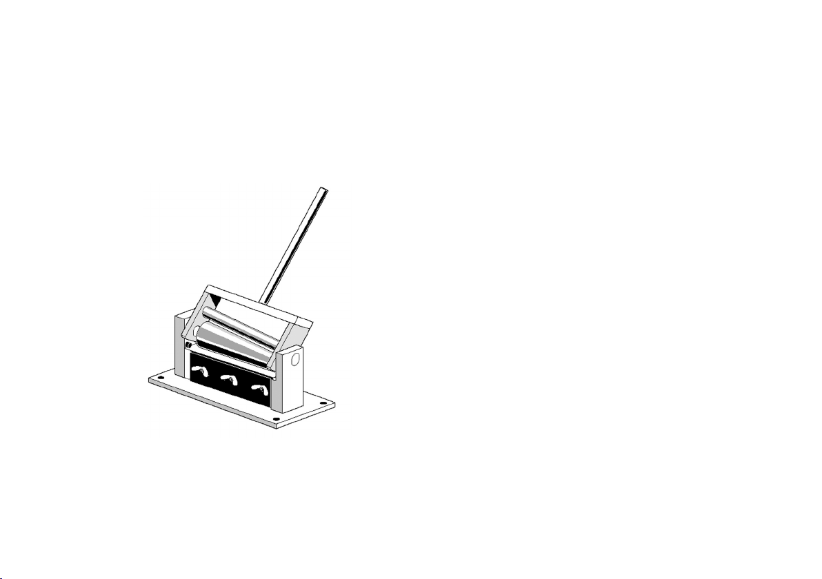
Abb. 1 Dornbiegeversuch

2. Messung
• Biegehebel in die untere,
horizontale Position bringen.
• Es ist ratsam, die beschichtete
Seite des Prüfbleches mit einem
Blatt Papier abzudecken, um
mechanische Verletzungen des
Films zu vermeiden.
Beurteilung der Probeplatte
Sofort danach wird die Beschichtung auf Rißbildung und / oder
Ablösen vom Untergrund, entweder
mit bloßem Auge oder, nach Vereinbarung, mit einer Lupe von 10facher Vergrößerung untersucht.
• Das Prüfblech mit der beschich teten Seite zur Ziehwalze zwischen
konischem Dorn und Blechgegen halter (Ziehwalze) so in das
Prüfgerät einsetzen, daß eine
kürzere Seite das dünne Ende
des Dorns berührt.
• Das Prüfblech durch Anziehen der
3 Flügelmuttern fest einspannen.
• Biegehebel gleichmäßig innerhalb
von etwa 2-3 Sekunden (15
Sekunden nach ASTM) um ca.
180° nach oben um den konischen
Dorn ziehen und damit das
Prüfblech biegen,
• Die Stelle markieren, an der die
Rißbildung aufhört.
Die Länge des Risses wird vom
dünnen Ende des Dorns aus entlang der Probeplattenoberfl äche in
cm gemessen. Aus drei Prüfungen
ist der Mittelwert zu bilden. Das Ergebnis wird auf ganze cm gerundet
angegeben.
Achtung: Die Prüfung und Auswertung ist unter Zuhilfenahme der DIN
EN ISO bzw. ASTM Normen durchzuführen.

2. Lieferumfang /
Lieferhinweise
Lieferumfang
Dornbiegeprüfer, konisch
aus Aluminium, eloxiert
mit konischem Edelstahldorn
Meßbereich: 1/8 in. bis 1 1/2 in.
(3,2 bis 38 mm)
Dorndurchmesser
Lieferhinweise
Katalog-Nr. PF-5750
Conical
Mandrel Bending Tester
Cat.-No. PF-5750
Contents
1. General
2. Measurement Procedure
3. Components / Ordering Guide
Technical data are subject to alterations.


1. General
Test in accordance with
ASTM D 1737
withdrawn in 1988 and replaced by:
ASTM D 522
DIN 53150
DIN EN ISO 1519
DIN EN ISO 6860.
Bending a coated sheet metal over
a defi ned radius allows an indication
of the elongation and adhesion of a
paint fi lm at bending stress. The
ASTM and ISO standards describe
the test method by means of a
conical mandrel. The use of a
conical mandrel bending tester
enables testing of a large variety of
bending radiuses at the same time.
The conical mandrel consists of an
20 cm (8 in.) long metal cone with a
diameter decreasing from 38 mm
(1 1/2 in.) to 3.2 mm (1/8 in.).
The mandrel is mounted on a base
plate in a horizontal position. An
operating lever with a drawbar is
provided for bending the test panel
around the mandrel. The instrument
is also equipped with a device for
clamping the test panel.

Fig. 1 Bend Test

2. Measurement Procedure
• Place the bending lever into its
lower, horizontal position.
• It is recommended to cover the
coated side of the test panel with
a sheet of paper to avoid
mechanical damage of the fi lm.
Evaluation of the Test Panel
Examine the coating immediately
for cracking and / or detachment
from the substrate either with the
unaided eye or, by agreement, with
a lens of 10fold magnifi cation.
• Slip the test panel with the coated
side towards the drawbar
between mandrel and drawbar
and in such a position that one
short edge touches the narrow
end of the mandrel.
• Fixedly clamp the test panel using
the 3 thumb nuts.
• Move the bending lever
continuously to the upper position,
thus bending the test panel over
the mandrel through 180° in about
2 - 3 sec. (15 sec. according to
ASTM).
• Mark the point at which the
cracking stops.
The length of the extent of cracking
is measured in cm along the test
panel from the small end of the
mandrel. Calculate the mean value
of three tests and report the result
to the nearest centimetre.
For a procedure evaluation consult
the DIN EN ISO or ASTM
standards.

2. Components /
Ordering Guide
Components
Conical Mandrel Bending Tester
made of anodized aluminum
with conical stainless steel mandrel
Measuring range: 1/8 to 1 1/2 in.
(3.2 to 38 mm)
mandrel diameter
Ordering Guide
Catalog No. PF-5750

Mandrin de pliage
conique
N° Réf. PF-5750
Table de matières
1. Informations générales
2. Mode opératoire
3. Fourniture /
Informations sur la livraison
Sous réserve de modifi cations techniques.


1. Informations générales
Essai selon les normes
ASTM D 1737
a été annulée 1988 et remplacé près:
ASTM D 522
DIN 53150
DIN EN ISO 1519
DIN EN ISO 6860.
Le pliage d'une bande de tôle
vernie sur un diamètre defi ni permet
d'examiner l'aptitude à
l'allongement et la propriété
adhésive d'une peinture sous
contrainte de fl exion. Les normes
ASTM et ISO décrivent l'essai de
pliage sur mandrin conique. A l'aide
du mandrin conique il est possible
de couvrir une étendue de
diamètres de pliage différents par
un seul essai.
Le mandrin conique consiste en un
cône tronqué 8 in. (20 cm) de long,
d'un diamètre diminuant de 1 1/2 in.
(38 mm) à 1/8 in. (3,2 mm).
Le mandrin est monté dans une
position horizontale sur une
embase. A l'aide d'une poignée de
manœuvre le panneau d'essai est
plié sur le mandrin. L'appareil est en
outre muni d'un dispositif pour
serrer le panneau d'essai.

Fig. 1 Essai de pliage

2. Mode opératoire
• Abaisser la poignée en position
horizontale.
• Il est recommandé de couvrir le
panneau díessai soigneusement
avec du papier pour emballage du
format du panneau pour éviter un
dégàt mécanique du fi lm.
• Introduire l'échantillon et le papier
entre le mandrin conique et la en
pièce de pliage - le côté vernis en
direction de la pièce de pliage de telle sorte q'un bord court du
panneau touche le diamètre
minimal du mandrin.
• Serrer l'échantillon et le papier les
fermement en utilisant les trois
écrous à oreilles.
• Relever la poignée régulièrement
en pliant ainsi à 180° le panneau
d'éssai sur le mandrin conique, la
durée du mouvement étant 2 - 3
sec. environ (15 sec. selon ASTM).
Evaluation du panneau d'essai
Examiner immédiatement
chantillon pour constater
l'apparition de craquelures ou de
décollement du fi lm, à l'œil nu ou
suivant accord, en utilisant une
lentille de grossissement 10.
Noter la longueur des craquelures
en cm à partir du diamètre minimal
du mandrin le long du panneau.
Calculer la moyenne de trois
résultats obtenus. Indiquer le
résultat en cm arrondis.
Pour une évaluation veuillez voir
les normes DIN EN ISO ou ASTM.
• Marquer le point où on ne peut
plus constater de craquelures.

3. Fourniture /
Informations sur la
livraison
Fourniture
Mandrin de pliage conique
en aluminium anodisé
avec un mandrin conique en acier
spécial
Gamme de mesure
du diamètre du mandrin:
1/8 in. à 1 1/2 in.
(3,2 à 38 mm)
Informations sur la livraison
N° Réf. PF-5750

Mandrino Conico
No di cat. PF-5750
Indice
1. Generale
2. Procedura
3. Guida all'ordine
I dati tecnici sono soggetti a modifi che.


1. Generale
Il metodo di prova è conforme alla
ASTM D 1737
revocata nell' 1988 e sostituito vicino:
ASTM D 522
DIN 53150
DIN EN ISO 1519
DIN EN ISO 6860.
La piegatura di una lamiera di
metallo verniciato su un raggio
defi nito dà un’indicazione
dell’allungamento e l’adesione di
un fi lm di vernice sotto stress di
piegatura. Le norme ASTM e ISO
descrivono il metodo di prova per
mezzo di un mandrino conico. L’uso
di un mandrino conico permette la
prova su una grande varietà di raggi
di piegatura nello stesso tempo.
Il mandrino conico consiste di un
cono di metallo lungo 20 cm (8 in.)
con un diametro decrescente da 38
mm (1 ½ in.) a 3.2 mm (1/8 in.)
Il mandrino viene montato su una
piatto base in posizione orizzontale.
Viene fornita una leva operatrice con
una barra per piegare il pannello
intorno al mandrino. Lo strumento
è anche fornito di pinza per fi ssare
il pannello di prova.

Fig. 1 Test di piegatura

2. Procedura
• Porre la leva piegatrice nella sua
posizione orizzontale più bassa.
• Si raccomanda di coprire la parte
verniciata del pannello di prova
con un foglio di carta per evitare
danni meccanici al fi lm.
• Far scivolare il pannello di prova
con la parte verniciata verso la
barra tra mandrino e la barra e in
posizione tale che un bordo corto
tocchi la parte fi nale stretta del
mandrino.
• Fissare il pannello di prova con
la pinza usando i 3 dadi.
• Muovere la leva piegatrice in
maniera continua e uniforme nella
posizione superiore, piegando
così il pannello di prova sul
mandrino per circa 180° in circa
2-3 secondi (15 secondi secondo
le ASTM).
Valutazione del pannello di prova
Esaminare immediatamente la
vernice per le crepe e/o il distacco
o ad occhio nudo o, convenzionalmente, con una lente 10x.
La lunghezza dell’estensione della
crepa viene misurata in cm lungo
il pannello di prova dalla parte più
piccola del mandrino. Calcolare il
valore medio di tre prove e riportare
il risultato al centimetro più vicino.
Per una valutazione della procedura
consultare le norme DIN EN ISO o
ASTM.
• Marcare il punto in cui la crepa
termina.

3. Guida all'ordine
No di cat. PF-5750Strumento di piegatura con
mandrino in alluminio anodizzato,
con mandrino conico in acciaio
inossidabile.
Campo di misura:
diametro del mandrino da
1/8 in a 1 ½ in. (da 3.2 a 38 mm)

BYK-Gardner GmbH
Lausitzer Str. 8
D-82538 Geretsried
Germany
Tel.: 0-800-gardner
(0-800-4273637)
+49-8171-3493-0
Fax: +49-8171-3493-140
www.byk.com/instruments/
BYK-Gardner USA
9104 Guilford Road
Columbia, MD 21046
USA
Phone: 800-343-7721
301-483-6500
Fax: 800-394-8215
301-483-6555


205 012 573 DEFI 0208
 Loading...