


Additives & Instruments
A member of
Measure what you see.
cloud-runner
Manual

cloud-runner
Manual
Patent pen ding 270 021 236 E 1010
BYK-Gardner GmbH
Lausitzer Str. 8
D-82538 Geretsried
Germany
T el. 0-800-gardn er
(0-800-427363 7)
+49-8171-3493-0
Fax +49-8171-3493-140
ww w .byk.com/instruments
BYK - Gardner USA
9104 Guilford Road
Columbia, MD 21046
USA
Phone800-343-7721
301-483-6500
Fax 800-394-8215
301-483-6555
1

Dear customer,
thank you for having decided for a BYK-Gardn er
product. BYK-Gardner is committed to providing you
with quality products and services. We offer
complete system solutions to solve your problems
in areas of gloss and physical properties. As the
basis of our worldwide business , we strongly believe
in total customer satisfaction. Therefore, in addition
to our products, we offer many VALUE-ADDED
services:
· T echnical Sales Force
· T e chnical & Application Support
· Application and Technical Seminars
· Repair & Certification Service
BYK-Gardner is part of Altana AG and a direct
subsidiary of BYK-Chemie GmbH, a leading supplier
of additives for coatings and plastics. T ogether, we
offer complete and unique solutions for you, our
customer.
Thank you for your trust and confidence. If there is
anything we can do better to serve your needs, do
not hesitate to let us know.
Y our BYK-Gar dner Team
2

T able of contents
T able of conten ts
1. Saf ety instr uct ions ............................................................................. 5
2. Syste m descr iption and De livery notes ...........................................11
Storage structure ................................................................................................ 11
3. Power s upply....................................................................................14
3.1 Rechargea ble b a ttery p ac k ...................................................................... 14
3.2 Docking station power supply ................................................................. 15
3.3 Charging the rechargeable battery ......................................................... 15
4. Controls.............................................................................................16
5. Getti ng st art ed ..................................................................................1 8
5.1 T urning the unit on and measuring ......................................................... 18
5.2 Display of mea su reme n t res ults ............................................................. 2 0
6. Te sting t he ins trum ent......................................................................21
7. Menu opera tion ................................................................................22
7.1 Navi gati on................................................................................................... 22
7.2 Overview of main menu ............................................................................ 23
7.3 Changing names and numbers ............................................................... 24
8. Measur e ............................................................................................2 5
8.1 Measure ...................................................................................................... 25
Interrupt Checkzone ........................................................................................... 27
Parameter Info .................................................................................................... 27
End Test Series ................................................................................................... 27
8.2 ME MORY..................................................................................................... 28
8.3 Orga nizer ....................................................................................................... 2 9
8.4 Memory with Para meter Inpu t ................................................................. 3 1
9 Configuration.................................................................................... 33
9.1 Number of Mea sure ments ....................................................................... 3 4
9.2 Scanlength ................................................................................................. 3 4
9.3 Angles ......................................................................................................... 3 4
9.4 Scale s ......................................................................................................... 3 5
3

T able of contents
10. A dvanc ed Confi guration....................................................................3 6
10.1 Interrupt .......................................................................................................36
10.2 Input Para meter 2, 3 and Comment .........................................................36
10.3 Input ID .........................................................................................................36
10.4 Input Checkzone .........................................................................................36
11. Memor y.............................................................................................37
11.1 Configuration New ......................................................................................37
11.2 Configuration Change ................................................................................38
11.3 Configuration Delete ..................................................................................38
11.4 Data Vie w.....................................................................................................39
11.5 Data Delete ..................................................................................................40
12. Setup................................................................................................. 41
12.1 Beeper..........................................................................................................41
12.2 Confirm with mode .....................................................................................41
12.3 Language .....................................................................................................41
12.4 Info................................................................................................................42
12.5 Date / Time ...................................................................................................42
12.6 Display Time ................................................................................................42
13 . Installation of s oftwa re..................................................................... 43
14 . Interface............................................................................................4 4
15. Technical Data.................................................................................. 45
16 . Info and Err or m essa ges ..................................................................4 7
17. Cleaning and maintenance ............................................................. 51
18. Service and Certification ................................................................53
19. Copyright ..........................................................................................55
4

1. Safety instru ctions
• Before operating the instrument the first time,
• If you use the unit and accessories properly,
• This product is equ ipped with safety features.
• No claims of product liability or warranty can be
• Keep these instructions for future reference.
Safety instructions
please read the operating instructions and take
particular notice of the safety instructions.
there are no hazards to fear .
Nevertheless, read the safety war nings carefully
and use the product only as described in these
instructions to avoid accidental injury or damage.
honored if the device is not operated in
accordance with the operating instructions.
• If you pass this instrument to somebody else,
make sure to include these instructions.
5

Safety instructions
The following symbols and terms are used.
This symbol warns of the danger of injury.
This symbol warns of the danger of injury caused by
electricity .
This sign points out add itional information.
DANGER
The term DANGER warns of pos sible severe
injuries and da nger to life.
WA RNING
The term WARNING warns of injuries and severe
material damage.
CAUTION
The term CAUTION warns of slight injuries or
damage.
6

Safety instructions
DA NGE R injur ies poss ible
• Defects and extraordinary loads
If safe operation can no longer be presumed,
shut down the device and secure it against
unintended operation.
The device must be presumed unsa fe to operate:
• if visible damage is evident
• if the instrument is no longer working
• if it has been stored for long periods under
adverse conditions
• after hars h treatment during shipping.
• Safety advices for batteries: Do not crush or
dismantle, do not heat or incinerate, do not
immerse in any liquid. This may cause explosion
or release harmful substances.
• Do not perform any repairs on the unit yourself.
The unit must be opened by trained
professionals only. Please contact our customer
service department in such cases.
• The measu rement device may be disconnected
from any power source as follows:
a) by removing the rechargeable battery pack
Docking station:
a) by disconnecting the plug from the docking
station or from
b) the mains socket.
Please make certain that the power supply plug is
easily accessible. Use only the power supply
included with delivery.
7

Safety instructions
• When working with the batteries make certain
there is no short circuit on the contacts. Metallic
objects must not come in contact with the bare
contacts.
WARNING severe materi al damag e
• The measurement unit consists of sensitive
optical and electronic precision parts. Prevent it
from being dropped, bumped or shaken!
• Avoid exposure to continuous hu midity and
condensation. A void splashing with water ,
chemicals or other liquids.
• Please use only accessories that are available
for the unit.
• Only devices that meet the requirements for low
voltage safety may be connected to the
interface.
8

Safety instructions
CAUTION material d amag e
• Do not allow any foreign objects to get into the
measur ement opening .
• Do not expose the unit to direct sunlight for
extended periods of time. Do not store it in a hot
or dusty environment. Use the instrument case
for storage.
• Recharg eable Li-Ion battery packs: Do not
charge at temperatures below 0°C. The allowable
discharge temperature range is -20 to +60°C.
Please refer to the charging instructions in
section „Power Supply“.
• D o not us e a ny a c e tone for clea ning the
unit! The unit housing is resistant to many
solvents. For cleaning you should use a soft,
moist cloth. Excessive dirt and dust can be
removed with ethanol or cleaning alcoho l.
• In case you intend not to use the instrument for
a longer period of time, take out the batteries.
Addit onal infor mation on use:
• You will find the technical data for all system
components on the res pective manufacturer’s
plates and in the section T echnical Data
• Batteries are special waste and must therefore
not be disposed of with household trash. Make
certain to observe the disposal instructions of the
battery or rec hargea ble battery manufacture r.
9

System description and Delivery notes
2. System description an d Deli v er y notes
Please read the instruction manual before using the
instrument and note the safety instructions.
The instrument simulates visual evaluation under
different obse rving angles and ch aracterizes clouds /
mottles by their size and visibility.
The measurement system consists of the portable
measurement device, docking station and the
smart -char t progr am.
Depending on the application, the system can be
used in various ways, from single measurements in
R & D up to routine quality control procedures (e.g.
automobile).
In order to guarantee a flexible data analysis, it is
essential to allocate the data to a clearly defined
object (identification).
10
The so-called “Organizer” file clearly defines the
object to be measured. The Organizer needs to be
created in the smart-chart software and defines the
measurement s equence ( sampling proce dure). This
file is transferred to the instrument then to guide the
user d uring measur ement.

Storage structure
System description and Delivery notes
The saved results are transferred to the PC and
displayed as a QC report.
The data is saved in a database for further analysis
over time. Pre-prepared test reports in the smartchart software assist in analyzing the data.
Each measurement series contains a header and
the individual measurements with name (test zon e)
and measured values.
In the header, up to 5 par ameters can be defined for
object identification. Parameters 1 to 3 are defined
in the Organizer file, parameters 4 and 5 can be
entered before storage in the data base.
Additionally, date and time of the measurement are
stored.
This structure determines the data organization in
the instrument and in the data base. In addition to
using Organizers, i. e. definition of parameters
before
the measurements, parameters and test
zones can also be entered during the
measu rements . See cha pter “Memo ry”.
11

System description and Delivery notes
Application hints:
Measurement task
1. Single measurements, e.g.
occasiona l sample-measurements
2. Objects with several test zones.
T est sequ ence / identifikation can be
standardized, e.g. automobile or addon parts
3. Regular test series. Test
sequence / identifikation can be
standardized, e.g. batch control
4. Occasional test series. Test
sequence / identifikation can not be
standardized, e.g. projects
Recommendation
- Me nu “Meas ure“ > “MEM ORY“.
- Transfer results to smart-chart.
- Generate Organizer in smartchart and transfer it to the
instrument.
- T ake readings, see chapter 8.3.
- Transfer results to smart-chart
and store in data base.
- Data analysis smart-chart.
see 2.
- Generate new Memory (chapter
Memory, Config. New).
- T ake readings, see chapter 8.2.
- Transfer results to smart-chart.
12

System description and Delivery notes
cloud-runner AM-6350
Comes complete with:
Mottling meter with pr otective cover, Reference tile
with certificate, smart-chart software on CD,
Docking station with USB cable, 2 rechargeable LiIon battery packs, Operating manual, Carrying case.
Acces sories and Replacements:
Reference Tile AM-6353
Docking S tation AM-6351
Battery Pack AM-6349
smart-chart sofware AW-4831
13

Power sup ply
3. Power supply
Before operating the instrument for the first time,
please read the operating manual and take
particular notice of the Safety Instructions. Unpack
the instrument and check the delivery for
completeness (See chap ter “Delivery Notes”).
Powering the ins trument
The measurement unit is operated with the
Rechargeable
batt ery pack
3.1 Rechargeable battery pack
rechargeab le battery pack included w ith delivery.
T o place the instrumen t in service, the rechargeab le
battery pack must be inserted until it locks in place.
The battery pack can only be attached when it is in
the correct position.
When inserting the battery pack, ensure that its
contacts are aligned with those of the instrument.
See adjace nt figure.
The capacity of the rechargeable battery pack
included with de livery is sufficient for about 1000
measurements. When the voltage of the battery
pack falls below the requ ired operating voltage in the
course of operation, the following messag e appea rs
on the display:
“Low Battery!”
14
Note: To ensure uniform utilization, the rechargeble
battery packs should be exchanged regularly
between instrument and docking station (weekly
recommended).

3.2 Docking station power supply
Power is supplied to the docking station through the
external power supply unit. Connect the external
power supply unit to the docking station. Connect
the appropriate end of the power connection line to
the power supply unit and the plug end of the power
connection line to the pow er outlet after verifying
that the specifications of the power supply unit
match the power source in terms of current and
voltage.
3.3 Ch arg i n g t h e rech arg eab l e bat tery
The rechargeable battery pack included with delivery
may be charged in the docking station. Charging
time for an empty battery pack is aprox. 2 hours.
Please note chapter “Safety Instructions”!
1. Battery pack in the instrument:
The lithium ion rechargeable battery will begin
charging immediately upon insertion of the
instrument into the docking station. To do this,
power must be supplied to the docking station
through the correspo nding power s upply unit.
Insert the measurement unit into the docking station
as show n in the neighboring illustration.
2. Battery pack on docking station:
A second charging shaft is located behind the shaft
for the instrument. Insert the second battery pack
here for charging, so it will be handy at any time to
replace the other battery when it is discharged.
Power sup ply
1 2
Charging indicator for:
1: additional battery pack
2: ins trument
Indication light:
green:ready
red: charging
15

Contr ols
4. Controls
2
1
3
7
4
5
6
Measur ement unit
1 Mode scroll wheel: Menu selection
2 Display for user guidan ce and meas urement values
3 Signal lamp
4 Operate button: Turn on, measurement and confirmation of menu items.
5 Measur ement aperture
6 Cover
7 Opening for hand strap
16

Contr ols
The basic system consists of the measurement
device and the docking station.
The docking station is used to exchange data and
to charge the rechargeable battery pack.
When the unit is not in use, place it in the docking
station. In this way the rechargeable battery pack
will be charged and the instrument will always be
ready for measurements.
The operate button and scroll wheel are used to
control the system. Pressing “operate“ turns the unit
on and causes a menu to be displayed. All settings
within the menus are made by turning the wheel and
pressing “operate”.
Pressing the o perate button performs
measurements or runs selected functions. System
operation is supported by an autodiagnosis test,
comments and error messages. Measurement
values and comments appear in the display.
17

Getting started
5. Getting st arted
5.1 Turning the unit on a nd mea suring
Turn the instrument on by pressing the operate
button.
If the operate button is depressed while switching
the unit on, a reference to the firmware appears
along with the date of the last certification.
The unit then switches to the last measurement
mode to be selected.
If no measurement mode has been previously
selected, the main menu appears. For the first
steps, select MEMORY under the “Measure” menu.
T o perform a measurement, press and hold the
operate b utton.
Move the instrument evenly and slow ly over the
sample surface.
18
During the measurement, the following information
appears in the display:
The upper bar shows the progress of the
measurement, while the arrow shows the scan
direction. The two lower bars provide information
about the status of the memory and battery
capacity.

Getting started
After completing a measurement, a signal is heard
and the measurement results are displayed.
Performing the measuremen t requires so me
practice. The following error messages a re
especially likely to occur during the first trials.
A warning signal is heard and the light diode flashes
at a rapid rate. At the same time, a message
appears in the display indicating the type of error:
Speed
Y ou have moved the measurement unit too quickly
or unevenly over the s ample. Confirm this
information by pressing the operate button and
repeat the measurement.
Scan length
The required scan length has not been reached
completely .
Repeat the meas urement, moving the device until a
short audio confirmation is heard.
Small areas can be measured by moving the
instrument back and forth.
Direction
The scan direction was changed.
Confirm the message by pre ssing “opera te” and
repeat the measurement.
19

Getting started
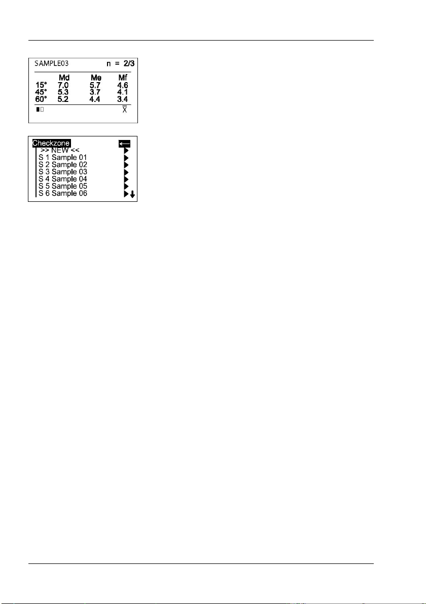
5.2 Display of measurement results
The measurement resu lts displayed w ill vary
A B
C
depending on the options selected in the
Configuration (see chapter 9, 10). Displayed results
may be broken down into the following elements:
A: Name of the measured sample or checkzone.
B: The number of performed and predefined
measurements (e.g. 2 of 3). The statistic function is
activate if the predefined number of measurements
is greater than 1.
C: The black rectangle shows the active page of the
display. You can access the second page by turning
the scroll wheel. If only one page is active, only one
rectangle is shown.
The measurement values appear in the lower part of
the display area.
Pressing the operate button now , the values will
disappear and the number of readings is increas ed
by one. Or, if a sample is finished, the name of the
next checkzone/sample will be displayed.
20
T o exit the measurements, press the scroll wheel. A
menu for deleting, interrupt or ending the series
appears. Use the scroll wheel to move the cursor to
“End T es t Series” and press operate. The display
switches to the Measure menu after a request for
confirmation.

6. Testing the instrument
Due to the measurement principle, calibration of the
equipment is not necessary. It is recommended,
however, to check the functionality of the instrument
at regular intervals (abou t once every 3 months). The
reference tile include d with delivery is provided for
this purpose.
Select the “Standard” in the Measure menu. The
configuration of this organizer is fixed and cannot be
changed.
The unit then switches to the measurement mode.
Place the instrument on the test tile as shown
above and perform three measurements.
If the values measured on the re ference tile are
within the printed tolerance range, the re quirements
are met.
If the mean value is not within the desired tolerance
range, try carefully cleaning the test tile. If this
produces no improvement, please con tact our
Customer Service department.
Reference tile:
T o ensure a precise instrument test, only original
test tiles from the manufacturer should be used.
Their surface must not be touched and must be
protected against scratches . Due to environmental
influences, however, the values of test tiles can
change over the course of time even if they are
handled gently. For this reason, have the test tiles
checked by the manufacturer at regular intervals
(annual checks are recommended). For cleaning the
test tile refer to chapter 17.
T es ting the instrument
21

Menu operation
7. Menu operation
7.1 Navigation
*
All functions are controlled by the mode scroll wheel
and the operate button.
Pressing the operate button or the scroll wheel
causes a menu to appear in the display. Turning the
wheel allows you to move the cursor to the desired
function. Select or activate the function by pressing
the operate button.
The following symbols can be found througho ut the
menus to aid navigation:
A black triangle to the right of a function indicates
that selecting this function will open a sub-menu.
The arrow at the top right is used to move back one
level within the menu system.
A check mark on the right indicates that the function
in question has been activated.
In submenus which require a selection, the actual
setting is indicated by a dot.
The star guides you to the Language menu.
22

Menu operation
7.2 O verview of mai n men u
Measure
MEMORY Default memory for single measurements
MY MEMORY User-defined memory (appears only if
generated under “Memory” menu)
Standard T o verify the device function on the test panel
My Model Measurement with Organizer (appears only if
loaded from PC)
Memory
Config. New Create a ne w memory
Config. Change Change the settings of a memory
Config. Delete Delete a memory
Data View View measured data of a memory
Data Delete Delete measured data
Setup Cha nge the language, date/time and switch-
off time; activate audio s ignal and
confirmation by scroll wheel.
23

Menu operation
7.3 Changing names a nd numbers
For some functions, you can enter or change the
date or name. The triangle pointing upw ard marks
the item that can be changed. T o change the
character, turn the scroll wheel. When you press
the scroll wheel, the arrow jumps to the next
charac ter .
After you have adjusted the last character, confirm
your input by pressing the operate key.
A confirmation message appears which allows you
to save the settings or change incorrect entries. Use
“Cancel” to exit the function without making any
changes.
24

8. Measure
8.1 Measure
Measure
For beginning a new test series, select Measure
from the Main Menu. The Measure menu offers a list
of names to identify the new test series
(Parameter1). Individual entries can be added to t he
list.
Two types of test procedures can be differenciated
by a symbol in front of the names:
Memories:
generated in the instrument, allow to input
identification parameters during measurement
procedure.
Organizer:
down loaded from the smart-cha rt softwar e, offer a
predefined test proced ure for user guida nce and
identification.
A virgin instrument contains only two entries in the
menu, which can not be deleted:
MEMORY - for simple measurement of samples.
Standard - for checking the instrument on the test
tile (see chapter 6)
Select a desired item from the list to start the test
series and perform the measurements according to
section 5.
Differences between the measurement procedures
will be explained in chapter 8.2 to 8.4.
25

Measure
T o exit a measurement series, press the scroll
wheel. A menu a ppears for deleting, interrupt and
ending the series:
Delete Last
Deletes the last measurement within a
checkzone.There is no ad ditional warning before the
deletion.
Delete Checkzone
Deletes the entire last checkzone. There is no
additional warning before the deletion.
Delete T est Series
Deletes the entire measurement series. A
confirmation display app ears before final deletion.
26

Interr upt Che ck zone
Parameter Info
End Test Series
Measure
This function allows you to exit a checkzone/sample
before reaching the pr eset number of measurements
or to skip a checkzone. Then you can continue the
measurement series with the next checkzone.
If Interrupt is not activated in the Configuration menu
(Chapt. 9) or the Configuration of the selected
Organizer, a message will be displayed.
Gives you an information about the selected
parameters of the sample.
Ends the entire measurement series. A confirmation
display appears. The instrument returns to the
Measure menu.
If Interrupt is not activated in the Configuration, a
message will be displayed in the case that the test
series is not finished yet.
Note:
Only complete series can be saved, i.e. you can
exit series only by deletion.
27

Measure
8.2 MEMOR Y
This is a memory with default settings for single
measurements on samples.
The settings can be changed for individual needs,
e.g. scale selection, statistics or scan length.
For further information pleas e refer to cha pter
“Configuration”.
Changes in the configuration are only possible if no
measurement data are s aved under the de sired
memory name. Before you change the configuration,
first backup the stored data and then delete them.
28

8.3 Organizer
Measure
An organizer file defines a test sequence for user
guidance, e. g. for measuring a car body with
several checkzones. These files can be generated
with the smart-chart software.
If no Organizer is loaded in the device, one must be
trans ferred from a PC.
Once an Organizer is selected, a menu appears for
Parameter 2 of the Organizer. Colors are listed as
an example of this in the menu to the side. After you
have selected the appropriate color, a selection
menu appear s for Parameter 3.
The illustrated example featu res automotive paint
line s.
If “Input Comment” is activated in the Organizer ,
you are prompted to enter ad ditional information.
If “Input ID” is activated in the Organizer , you are
prompted to enter a code, e.g. the vehicle ID.
Upon definition of all parameters, the following
measurement series is identified and the instrument
goes into measurement mode.
29

Measure
The name of the checkzone to be measured first,
appears on the left side of the display.
The number of performed and predefined
measurements (e.g. 2 of 3) appear in the upper right
corner.
Once the number of measurements for the
checkzone is reached, a double audio signal is
heard.
The display shows the results of the measurement
and indicates that the measurement of the
checkzone is complete (e.g.3/3).
Pressing briefly the operate button allows the next
checkzone to appear in the display.
The instrument is ready for the next measurement.
30
Once all checkzones have been measured, the
instrument returns to the Measure menu.

8.4 Memo ry w ith Parameter I np ut
By using the internal memory function of the
instrument, measurement series and samples/
checkzones can be identified by individual names
during the test procedure.
Therefore, input options of the menu item Advanced
Configuration nee d to be activated for the desired
memory.
Y ou can us e the existing MEMORY in the
instrument or create another memory name
(Parameter 1). For more information about cha nge of
configuration please refer to s ection Configuration.
Select a memory for which Input Parameter 2, 3,
Input Comment or Input ID are activated. A menu
appears to assign a name.
If there are preexisting names for this memory, they
are shown in a list for selection. The >>NEW<<
option opens another menu with a list of all names
available in the instrument. Here, the menu item
>>NEW<< opens an input mask which allows you
to create a new designation.
Enter the name by using the scroll wheel. When
finished, press the operate button.
A confirmation display appears which allow s to verify
that the entered data is correct.
Next, a selection menu may appear to enter an
additional para meter. Proceed a s des cribed above.
Measure
If a memory is selected that already contains
measurements, the test series can be continued.
A display appears to confirm this. By selecting No,
a new test series will be started.
The device goes to the measurement mode, you
can start taking readings.
31
Measure
Once you have reached the prese t number of
measurements (n = ...), you might be prompted to
enter a name for the checkzone (“Input Checkzone”
aktivated).
Proceed by entering the name of the checkzone as
described above for the parameters.
If “Input Checkzone” is deac tivated, the instrument
automatically assigns the name SAMPLE 01 and
then increments this name.
To exit the test series, presss the scroll wheel and
activate End T est Series.
32

9 Configuration
Configuration
For every memory, specific settings can be made
that affect the test procedure an d the evaluation of
the data.These s ettings are individually definable in
the Memory menu:
Config New
for a new memory
Config Change
for an existing memory
Once a memory is selected, the menu with the
various configuration items appears.
The complete contents of the menu are shown in
the neighboring illustration.
The current settings are displayed on the right side
next to the black triangles.
To exit the menu, scroll the cursor to
and press the operate button.
A display appears to confirm the changes.
33

Configuration
9.1 Number of Measurements
This function allows selection of the numbers of
readings to be taken per sample. If the number is
greater than 1, the measurements are statistically
evaluated. Turning the scroll wheel adjusts the
number while pressing it shifts the decimal place
one further over. Press ing operate completes the
process and a confirmation display appears.
9.2 Scanlength
The scanlength is adjustable between 10 and 100
cm in 1 cm steps to your individual needs. The little
black triangle shows the position to be adjusted.
Turn the mode wheel to adjust or press the wheel to
proceed to the next position. Pressing operate
completes the process and a confirmation display
appears.
Y ou can enter the scanlength alternatively by
pressing the operate button and by moving the
instrument over the surface to be scanned. Keep
the operate button pressed until the desired length
is reached. Then release the operate button. The
scanlength is displayed and you can confirm it by
press ing operate again.
9.3 Angles
34
Note:
Using a short scanlength will result in strong
statistical skewing of measurement values for large
mottle sizes (for minimum scan length please see
also under 9.4).
Three angles may be selected for the display of the
measurement results.
Select the desired angle and press the operate
button. A checkmark indicates the selected
angle(s).

9.4 Scales
Configuration
Eight scales may be selected for the display of the
measurement results.
Following scales are available:
Mottle S pe ctrum: Md...Mi
The measurement sign al is filtered into 6 different
ranges, which represent a s pecific range of mottle
sizes.
Mottle Ch art: T, M
a two-dimens ional evaluation of small and large
mottles.
T exture: a measure for mottles smaller ~ 25mm
Mottling: a measure for mottles larger ~ 25mm
Select the desired scale and press the operate
button.
Note:
Depending on the mottle size, a minimum scan
length is requ ired for measurement of:
Md to Mi 75 cm
Md to Mh 42 cm
Md to Mg 23 cm
Md to Mf 13 cm
Md to Me 10 cm
M 23 cm
35

Advanced Configuration
10. A dvan ced Configuration
10 .1 Interr upt
If statistic is activated in the configuration of the
selected memory (n > 1), you can interrupt a
checkzone (sample) before reaching the preset
number of meas urements.
10.2 I n put Parameter 2, 3 and Comment
When active, these parameters allow to assign
individual names for identification of a new test
series.
10 .3 Input ID
When this function is active, you can enter an
identification code e.g. vehicle ID number for each
new test series.
10 .4 Input Checkz one
When active, you can enter a des ignation for every
sample during a test series. When deactivated, the
instrument automatically assigns sample names
incrementally, beginning with SAMPLE 01.
36

11. Memory
1 1. 1 Configur ation New
Memory
In the Memory menu you can create new memories
with a configuration according to specific needs
(e.g. scales, statistics). Also, the configuration of
existing memories can be changed. Memories
which are no longer needed, will be deleted with the
function “Config Delete”.
Additionally, the menu allows to recall or delete a
measured test series.
After selecting this menu item, you will be prompted
to enter a name for the new Memory (Parameter 1).
Enter a name by using the scroll wheel. When
finished, press the “operate” button.
A display appears to check and confirm the entries.
The next step allows to copy the configuration from
an existing Memory or Organizer. Select the desired
entry from the list.
A menu will then appear with the copied
configuration for the new Memory .
T o change the settings, refer to chapter 9 and 10.
T o exit the menu, activate the arrow at the top of the
list. A confirmation display appears to complete the
creation of a new memory. The display now returns
to the Memory menu.
37

Memory
1 1 .2 Configura tion C hange
This function allows to modify the configuration of an
existing memory. A menu appears with a list of the
existing memories and organizers.
Select the desired memory.
A menu then appears listing the configuration of the
selected memory. T o change the settings, refer to
chapter 9 and 10.
T o exit the menu, activate the arrow at the top of the
menu.
Note: Changes to the settings of Organizer files are
not permitted. If an Organizer is selected, a warning
message w ill appear.
The configuration can only be changed if no
readings are s aved in the selected memory . Before
changing, first backup the readings and then delete
the data.
1 1 .3 Configuration D elete
38
The delete function opens the s election menu for the
memories wh ich are present.
Select the memory to be deleted.
A display appears to confirm the deletion process.
The instrument returns to the Memory menu.
Note: Deletion of a memory that contains
measurement data is not permitted.
If necessary, use the Data Delete function described
at the end of this chapter.
Deletion of an Organizer is only permitted if its
corresponding lock-function is deactivated in the
smart- chart s oftwa re (o rgan izer prote cted ).

11.4 Data V iew
Memory
Y ou can use this function to display all
measurement series stored in the instrument.
First, the selection menu for existing memories will
be shown.
Select the desired memory to recall its contents. If
the selected memory is identified by additional
parameters, further menus w ill appear:
Select Parameter 2.
Select Parameter 3.
As appropriate, select Comment and ID accordingly.
Finally, select the measurement series itself under
date and time.
The measurement values appear in the display.
Press the operate button to display the next
checkzo ne.
The numbers at the upper left of the display
represent the displayed/existing checkzone
numbers.
The checkzone name is displayed just below.
If more measurement data is present than can be
displayed, an arrow will appear on the right edge of
the display. Scroll down to view the remaining data.
Pressing the scroll will exit this display. The
instrument returns to the Memory menu.
39

Memory
11.5 Data Delete
This function deletes a desired test series stored in
the instrument.
Select the memory containing the data to be
deleted.
For the following selection of parameters and the
measurement series itself, please proceed as
described in the previous pa ragraph, Data View .
After selecting the desired test series, a display
appears to con firm the deletion.
The instrument returns to the Memory menu.
Note:
Measurement data of Organizers may only be
deleted if its corresponding lock-function is
deactivated in the smart-chart software(Organizer
protected).
40

12. Setup
12 . 1 Beeper
12 .2 Confirm with m ode
Setup
In the Setup menu you find functions to adjust the
following general settings of the instrument:
This menu option turns the beeper on or off. Use the
scroll wheel to move the cursor to Beeper and press
“operate”.
When the beeper is activated, a checkmark appears
at the end of the line.
Setting a checkmark on this option, activates the
function to select menu items by pressing the scroll
wheel too.
12 .3 Language
You can use this menu to select the display
language.
If a foreign language is activated actually, you
allways can find the language settings by following
the symbol in the menus.
*
Use the scroll wheel to move the cursor to the
desired language and press the operate key.
41

Setup
12.4 Info
12.5 Date / T ime
12.6 Display Time
This menu displays the following information about
the device:
• Catalog no
• Serial no
• Firmware version
• Free memory capacity
• Battery capacity
• Date of last certification
The unit contains an integrated clock. This makes
the date and time of the measur ement available for
data transfer to a PC. The date and time are not lost
even when the battery is changed. If necessary,
adjust the data by using the scroll wheel.
T o s ave energy, the unit automatically turns off after
a certain amount of time. You can determine what
this time is by specifying a switch off time between
15 and 99 seconds.
42

13. Installation of software
Before you install the software, make sure your
computer meets the following system requirements:
• Operating system: Windows® XP SP3 or higher
• Excel® version: 2003 incl. VBA
• Memory: min. 1GB
• Hard disk capacity: min 100 MB
• Monitor resolution: min 1280 x 1024 Pixel or higher
• Disk drive: CD-ROM or DVD
• Interface : Free U SB-Po rt
• Microsoft .NET Framework 3 .5 SP1
Running setup:
During installation full administrator rights are
necessary . You might need to contact your IT
support for this purpose.
After inserting the CD in the CD-ROM or DVD drive
Windows® starts the installation automatically. If
this is not the case, please run the file „install.exe“
in the main directory of the CD.
Follow the setup instructions on the screen.
Y ou are allowed to install and use the software on
up to two computers.
After successful installation the software can be
started via Start – Programs – BYK-Gardner –
smart-chart.
Installation of softw are
Note:
If you experience a limited functionality of the QCreports, please check the security settings of the
macro-function in Excel and set the level to
med iu m.
*Mi cros oft Wi ndows and E xcel ar e tradem arks of Mi cros oft C orp oration
43

Interface
14. In terface
Connecting the measurement unit to a PC
Data transfer to and from the measurement unit
takes place through the docking station. It contains
the USB interface connecting the instrument with a
PC.
The connection point for the USB cable is located
on the back of the docking station. Plug in the cable
included with delivery.
T o transfer data, the instrument must be inserted
into the docking station.
The data transfer itself takes place with the smartchart program, which is included with delivery .
Set up the computer and additional instruments as
described in the corresponding manuals. T o transfer
data, the connection cable must be connected to a
USB port. For the position and assignment of the
socket, please refer to your computer manual.
44

T echnical Data
15. Technical Data
General tech nical d ata:
T emperature range 10°C to 40°C (+50°F to 104°Foperation)
0°C to 60°C (+32°F to 140°F storage)
Rel. humidity up to 85% at 35°C (95°F), non-condensing
Measurement unit:
Application:
Clou d s ize Md 6 to 13 mm
Me 1 1 to 24 mm
Mf 19 to 42 mm
Mg 33 to 72 mm
Mh 57 to 126 mm
Mi 100 to 200 mm
Repeatability 5% or > 0.5 (standard deviation)
Reproducibility 8% or > 0.8 (standard deviation)
Object curvature > 500 mm
Scanlength 10 to 100 cm, selectable in 1cm steps
Smallest sample size 35 mm x 150 mm
Resolution 25 points / cm
Measuring Time < 4 sec.
Memory 1 000 reading s
Interface USB 1.1
Languages English, French, German, Italian, Japanese,
Portuguese,Spanish
Light Source White Power LED
Power sup ply rechargeable battery pack, approx. 1500 readings
Dimensions (WxLxH) 55 x 150 x 110 mm (2.2 x 5.9 x 4.3 in)
Weight 650 g (1.5 lbs.)
45

T echnical Data
Docking station:
Power sup ply 5 VDC; 2.5 A
Dimensions (WxLxH) 130 x 160 x 85mm (5.1 x 6.3 x 3.4 in)
Weight 450 g (1 lbs.)
External power supply:
Power sup ply Input: 100-240 VAC; 50/60 Hz; 800 mA
Output: 5 VDC; 4.0 A
Dimensions (WxLxH) 95 x 55 x 35mm (3.7 x 2.2 x 1.4 in)
Weight 320 g (0.7 lbs.)
46

16. Info and Error me ssages
Error
If an error occurs while using the instrument, the
display will indicate the error type.
Confirm the error by pressing the the operate button.
Repeat the process or the entry.
In the upper right corner, an additional number is
shown for service purposes.
Info
Informative displays always appear when deviceinternal settings or limits are reached or exceeded.
Confirm the message by pressing the the operate
button.
Info and error mess ages
47

Info and error mess ages
Error Messages
Identifies an interna l error . Load a firmware u pdate.
When in doubt, call the Customer Service
department.
The measurement unit was moved across the
sample too fast. The measurement is invalid and
must be repeated.
The operate key wa s releas ed before the full
scanlength was rea ched. Perform a new
measurement.
Day or month falls outside the valid range of 1 - 31
or 1 - 12. Repeat the entry.
Appears whe n the number of measurements in
“Memory-Config Change” is set to a value less than
1 or greater than 20. Repeat the setting with a value
between 1 and 20.
48
The specified year falls outside the valid range from
2000 to 2100. Please repeat the input with a valid
year.

Info and error mess ages
Error Messages
While adjusting the Display Time, you entered a
value outside the valid range from 15 - 99. Please
repeat the entry w ith a valid value.
Appears w hen the maximum number of
measurement series is reached for the selected
memory area.
No more free memory capacity available. Delete
measurement series w hich are no longer required.
Appears w hen you have measured 100 che ckzones
with one memory area. Create a new memory area
and continue your measurements.
When attempting to measure an Organizer near the
end of memory capacity, the instrument can detect,
based on the Organizer structure, that memory will
be exhausted before the en d of the measurement
series. It then generates this error before the
measurement b egins.
49

Info and error mess ages
Informa tion
The setting option “Interrupt” for the selected
memory is not activated or not allowed (Organizer).
Warning message indicating that measurement
values are present in the memory selected for
deletion.
Y ou can only assign a maximum of 100 sample
names per memory. That number has be en reached.
Y ou can only assign a maximum of 500 names for
Parameter 2 per memory. Tha t number has been
reached.
Y ou can only assign a maximum of 20 names for
Parameter 3 per memory. Tha t number has been
reached.
50
Y ou have ass igned an already existing name while
filing a memory area.
Y ou have attempted to change the settings of an
Organizer. Organizers cann ot be changed.
Y ou have attempted to delete a protected Organizer.
This notice appears when 95 % of the device
memory is filled.

17. Cleaning and maintenance
• Before cleanig, the instrument and accessories
must be disconnected from the power supply as
described in the safety instructions.
• Do not insert any objects into the measurement
aperture for cleaning. The instrument could get
damaged - a ffecting a pro per and s afe operatio n.
• Do not use any acetone! The instrument
housing is resistant to a number of solvents, but
cannot be guaranteed to withstand all chemicals.
Y ou should therefore use a soft, moist cloth for
cleaning. For cleaning excessive dirt, use
ethanol or cleaning alcohol.
• A cleaning mat to clean the unit’s wheels is
situated on top of the reference tile’s cover.
Therefore, roll the wheels several times over the
mat and then over a cleen sheet of paper. Dirt
will stick to the mat and can be removed with
clear water.
Cleaning a nd maintena nce
51

Cleaning a nd maintena nce
Cleaning the test tile
• Do not use any acetone!
The accuracy of the measurement can be
significantly impacted by using a dirty or
damaged test tile.
Since the surface of the test tile is highly
sensitive, cleaning must be undertaken with
great care.
T o clean the test tile, use a new lint-free cloth,
dust-free lens paper or an optical cloth.
Apply only slight pressure as you clean and
make certain there are no large particles stuck in
the cloth that could damage the surface.
For dirt that is difficult to remove, use an premoistened optical cloth. Then wipe the surface
with a dry optical cloth.
If the condition of the test tile seems doubtful
because of its appeara nce or measurement
errors, we will be happy to check it for you.
52

18. Service and Cer tification
Service
Besides the repair of your instrument we offer the
following ad ditional ser vices:
First diagnosis on the telephone or by e-mail
Call us or send us an e-mail and we will try to solve
your problem. If this is not successful, please send
us the instrument for repair.
Preventive main tenance, calibrati on, an d
recertification
For precautionary reaso ns we re commend regular
preventive maintenance. We carry out this preventive
maintenance automatically when you send us your
instrument for maintenance and rec ertification. We
clean the optics, check all functions, test and, if
required, adjust the measured values by using
reference standards . Y ou will receive a certificate,
which includes the retraceability to international
standards.
Loaners
During the period of repair we furnish you with a
loaner on req uest an d availability.
Maintenance agreement
In case you want to make sure that the necessary
maintenance is being done on a regular basis and
on time, we recommend a maintenance agreement.
Extended warranty contracts
Furthermore, you can request an extended w arranty
contract for additional 12 months.
Order ing infor ma tion:
SE-6350 extended warranty
Service and Certification
53

Service and Certification
Service Centers for BYK-Gardner products
Germany
BYK-Gardner GmbH
Lausitzer Strasse 8
82538 Geretsried
Germany
Phone:+49-8171-3493-0
Fax: +49-8171-3493-166
USA
BYK-Gardner USA
9104 Guilford Road
Columbia, MD 21046
USA
Phone:+1-301-483-6500
Fax: +1-301-483-6555
China
BYK-Gardner Shanghai Office
Room 1407, SIP AI PLA ZA
103, Cao Bao R oad
Shanghai 200233
P .R. C hina
Phone: +86-21 -6475-8570
Fax: +86-21-6475-7284
54
Brazil
BYK-Gardner La tin America
Rua das Aroeiras, 771
Bairro Jardim-Santo André-SP
CEP 09090-000
Brazil
Phone:+55-11-2147-1 199
Fax: +55-11-2147-1168

Copyright
19. Copyright
This instruction manual is an important part of this instrument. It co ntains essential information about setting up, placi ng in service and use. If you pass
the device on to another user , ple ase ensure that the instruction manual is
included with the instrume nt. The manual must be studied careful ly before
working with the equipment. Please contact your regional service office if
you have any questions or require additional information about the device.
The technology and fittings are based on state-of-the art optic and
electronic techno log y . New devel opments and innovati ons are co nstantly
being integrated into the equipment. Thus, the diagrams, dimensions, and
technical data used in this manual may have changed as a result of adapting
the device to new infor mation and improvements.
© Copyright 2010 B YK -Gardner GmbH
All righ ts reserv ed
No portion of the software, documentation or other accompanying materials
may be translated, modified, reproduced, copied or otherwise duplicated
(with the exception of a backup copy), or distributed to a third party, without
prior written authoriz ation from B YK -Gardner GmbH . In any case, this
requires the prior writte n consent of B YK -Gardner.
BYK -Gardner GmbH of fers no guarantee that the software wi ll functio n
without error or that the functions incorporated therei n can be executed in all
applications and combinations selected by you.
No liability other than as provided by law is assumed for direct or indirect
damage sustained in associa tion with the use o f the instrum ent, the software
or documentation.
BYK -G ardner GmbH reser ves the right to update the sof tware and written
documentation without prior notice .
55

270 021 236 E 1010
 Loading...