

Page 1
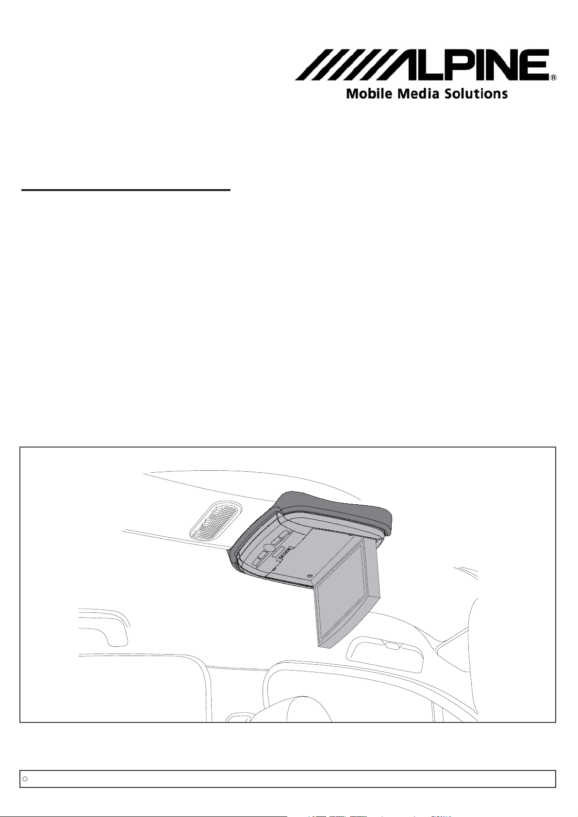
Renault Scénic
Deckenmonitor-Einbaukit
Installation kit for Rear Seat Entertainment
Kit d'assemblage pour écran de plafond
Kit de instalación para monitor de techo
Teilenummer/ Part number/ Référence/ Referencia
Änderungen des Lieferumfangs vorbehalten/ Equipment supplied is subject to alteration/ Ce produit est sujet à modifications sans préavis/ Sujeto a modicaciones sin previo aviso
RSE-K100SC
C
Copyright MS Design - Autotuning GmbH
Stand vom 22.12.09 Version 1.0/
Montageanleitung/ Mounting instructions/ Instructions de montage/ Instrucciones de montaje
1/12
Page 2
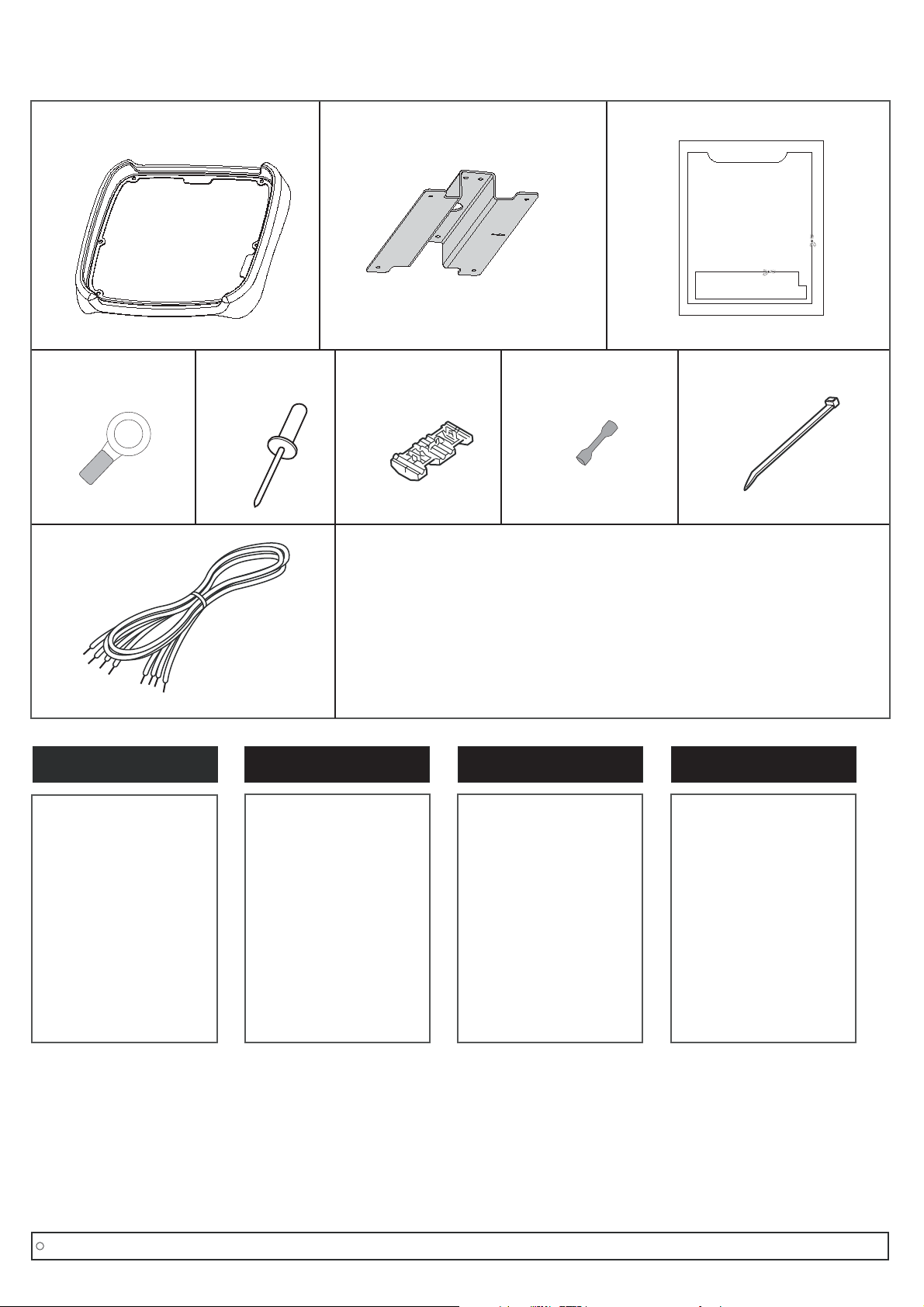
Stückliste / Parts list/ Liste de pièces/ Lista de componentes
4)
1)
9)
2)
3)
5) 6) 7) 8)
D
D
Pos. Bezeichnung Anzahl
1. Rahmen 1x
2. Halterung 1x
3. Schnittschablone 1x
4.
Ringkabelschuh 1x
5. Niete 5,0x12 6x
6.
Parallelverbinder 1x
7.
Quetschverbinder 4x
8.
Kabelbinder 5x
9. Ringkabelschuh 1x
GB
Item Description Quantity
1. Frame 1x
2. Mount 1x
3. Cutting template 1x
4.
Ring connector 1x
5. Rivet 5,0x12 6x
6.
Quick slide connector 1x
7.
Butt connector 4x
8.
Cable tie 5x
9.
Harness (extension) 1x
FR
Item Description Quantité
1. Garniture 1x
2. Entretoise 1x
3. Gabarit de découpage 1x
4.
Cosse annulaire 1x
5. Rivet 5,0x12 6x
6.
Clip rapide 1x
7.
Cosse 4x
8.
Collier 5x
9.
Faisceau (extension) 1x
ES
Item Descripción Cantidad
1. Marco 1x
2. Soporte 1x
3. Plantilla 1x
4.
Terminal de anilla 1x
5. Remache 5,0x12 6x
6.
Conector rápido de presión 1x
7.
Conector de empalme 4x
8.
Brida de plástico 5x
9.
Cableado (prolongación) 1x
C
Copyright MS Design - Autotuning GmbH
Montageanleitung/ Mounting instructions/ Instructions de montage/ Instrucciones de montaje
2/12
Page 3
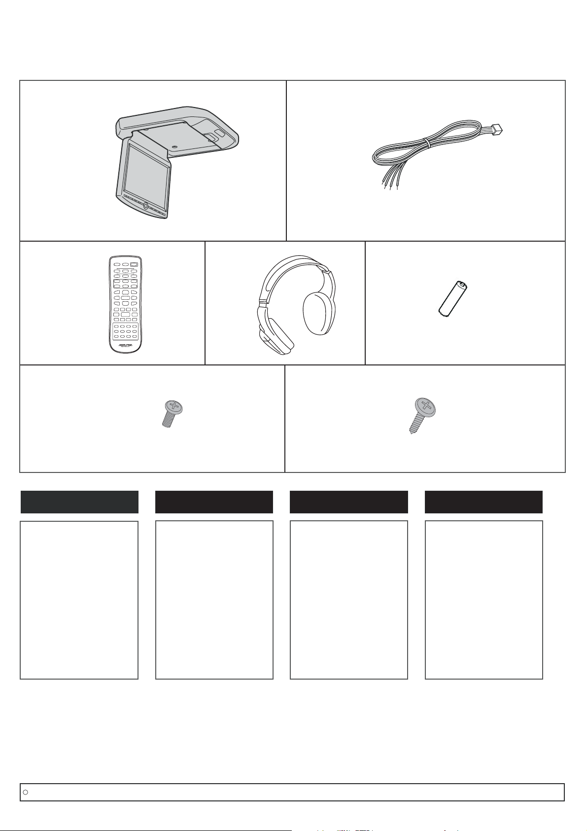
Im PKG Monitor Set enthalten / Included in PKG Entertainment Package/
Inclus dans l'emballage de l'écran PKG/ Incluido en el embalaje del PKG
a)
c)
d)
b)
e)
D
D
Pos. Bezeichnung Anzahl
a) DVD-Deckenmonitor 1x
b) Kabelbaum 1x
c) Fernbedienung 1x
d) Kopfhörer 1x
e) Batterien 4x
f) Schraube TB 3x8 6x
g) Schraube CM 4x8 4x
f)
GB
Item Description Quantity
a) DVD Overhead Monitor 1x
b) Harness 1x
c) Remote Control 1x
d) Headphone 1x
e) Batteries 4x
f) Screw TB 3x8 6x
g) Screw CM 4x8 4x
g)
FR
Item Description Quantité
a) Moniteur DVD plafonnier 1x
b) Faisceau 1x
c) Télécommande 1x
d) Casque 1x
e) Piles 4x
f) Vis TB 3x8 6x
g) Vis CM 4x8 4x
ES
Item Descripción Cantidad
a) Monitor de techo DVD 1x
b) Cableado 1x
c) Mando a distancia 1x
d) Auriculares inalámbricos 1x
e) Pilas 4x
f) Tornillo TB 3x8 6x
g) Tornillo CM 4x8 4x
C
Copyright MS Design - Autotuning GmbH
Montageanleitung/ Mounting instructions/ Instructions de montage/ Instrucciones de montaje
3/12
Page 4
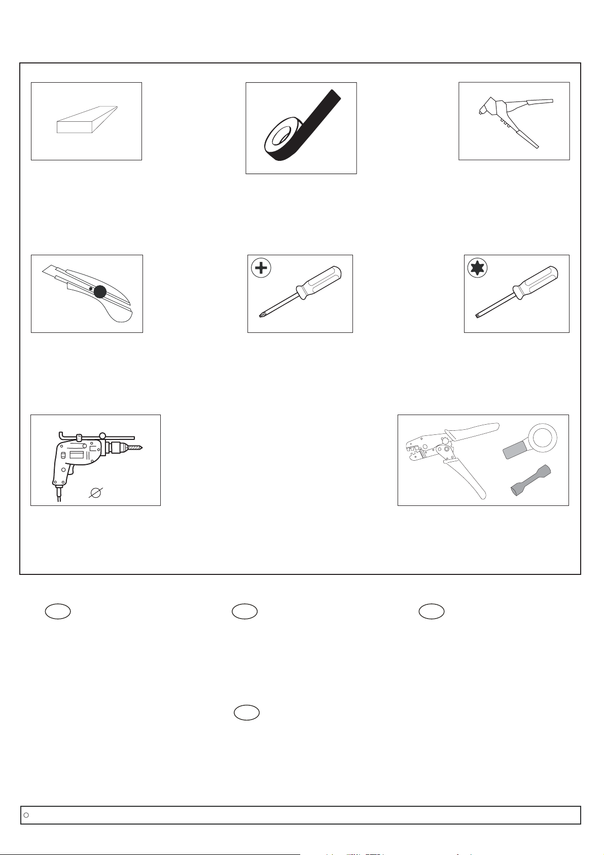
Werkzeuge / Tools/ Outils
Kunststoffkeil/
Plastic wedge/
Cale en plastique
Sacagrapas
Cutter-messer/
Cutter knife/
Cutter/
Cuchilla
Kreppband/
Crepe tape/
Adhésif papier/
Cinta adhesiva
Schraubendreher PH2/
Screwdriver PH2/
Tournevis Cruciforme Ph2/
Destornillador PH2
Nietzange/
Rivet gun/
Pince à rivets/
Remachadora
Schraubendreher torx T27;T30/
Screwdrivers torx T27;T30/
Tournevis Torx T27;T30/
Destornillado Torx T27;T30
5mm
Bohrmaschine/
Drill/
Perceuse/
Taladro
D GB F
Bitte die Montageanleitung vor Beginn
sorgfältig lesen.
Wir empfehlen die Montage in einer
Fachwerkstatt durchführen zu lassen.
Please read fitting instructions
thoroughly before commencing
installation.
We recommend that fitting is carried out
by a specialist workshop.
ES
Por favor lea minuciosamente las
instrucciones de montaje antes de
comenzar con la instalación.
Sugerimos que el montaje sea realizado
por un especialista.
Crimping tool for isolated connectors/
Alicate de engastar terminales aislados
iso
Crimpzange für isolierte verbinder/
Pince à sertir pour cosses ISO/
Lire attentivement la notice de
montage avant de commencer.
Nous recommandons de confier le
montage à un professionnel.
C
Copyright MS Design - Autotuning GmbH
Montageanleitung/ Mounting instructions/ Instructions de montage/ Instrucciones de montaje
4/12
Page 5

1
2
D
1. Innenraumleuchte und hintere Spiegeleinheit
ausclipsen.
2. A-Säulenverkleidung vorsichtig ausclipsen.
3. Seitliche Abdeckung demontieren.
GB
1. Unclip the interior lamp and the rear seat mirror.
2. Unclip the A-pillar cover carefully.
3. Dismount the side cover.
FR
1. Dé-clipper l'éclairage intérieur ainsi que le miroir
de vision des passagers arrière.
2. Dé-clipper délicatement le montant latéral
gauche.
3. Retirer le capot latéral gauche de la planche de
bord.
3
ES
1. Quitar la lámpara interior y el espejo retrovisor.
2. Quitar el plástico del pilar-A con cuidado.
3. Desmontar la tapa lateral.
C
Copyright MS Design - Autotuning GmbH
Montageanleitung/ Mounting instructions/ Instructions de montage/ Instrucciones de montaje
5/12
Page 6

4
5
D
4. Abdeckung unter der Handbremsbetätigung mit
geeignetem Werkzeug ausclipsen. Deckel des
unteren Ablagefachs entnehmen.
5. 2x Torx-Schrauben lösen und HandbremsBetätigung entnehmen.
6. Seitlich die gezeigten Torx-Schrauben entfernen.
GB
4. Unclip the cover under the handbrake. Dismantle
the lower console.
5. Remove both screws and dismount the control
parking brake switch.
6. Remove the shown torx-screws on the side.
FR
4. Dé-clipper la trappe située sous le frein à main.
Démonter la console inférieure.
5. Retirer les deux vis puis démonter le panneau de
commande de frein à main.
6
6. Retirer les vis torx situées sur le coté comme
indiqué.
ES
4. Quitar la tapa de debajo del freno de mano.
Retirar la parte inferior de la consola.
5. Soltar los dos tornillos y desmontar el interruptor
de parking.
6. Soltar los tornillos Torx visibles en el lateral.
C
Copyright MS Design - Autotuning GmbH
Montageanleitung/ Mounting instructions/ Instructions de montage/ Instrucciones de montaje
6/12
Page 7

7
8
D
7. Schraube links unten lösen.
8. Untere Armaturenverkleidung beginnend von
links ausclipsen. Die Verkleidung kann jetzt ein
Stück nach vorne gezogen werden, um den
Sicherungskasten leichter zu erreichen.
9. Mitgelieferte Schablone (3) ausschneiden, am
Himmel positionieren (kann ein wenig unter die
Abdeckung der hinteren Innenraumleuchte
geschoben werden) und mit Kreppband fixieren.
Nach dem Fixieren nochmals nachmessen, ob
die Schablone mittig sitzt.
GB
7. Remove the below screw on the left.
8. Unclip the dashboard cover on the left side. You
can’t remove the cover completely. It can be
pulled forward to allow you to reach the fuse box.
9. Cut out the provided template (3). Position the
template on the roof’s interior. Put a little bit of the
template under the interior lamp cover and fix it
with crepe tape. After that check the right position
again.
9
FR
7. Retirer la vis située sur la gauche comme
indiqué.
8. Dé-clipper la partie inférieure gauche du tableau
de bord. Elle ne peut par être retirée
complètement mais peut être repoussée de
manière à atteindre la boîte à fusibles.
9. Positionner le gabarit de découpage fourni (3), le
caler soigneusement en le coinçant légèrement
dans le support de l'éclairage intérieur. Ensuite, le
fixer à l'aide de l'adhésif papier.
ES
7. Soltar el tornillo inferior de la parte izquierda.
8. Quitar el plástico del salpicadero ubicado en la
parte izquierda. No puede extraer el plástico
completamente. Se puede tirar de el para permitir
alcanzar la caja de fusibles.
9. Cortar la plantilla suministrada (3). Posición de la
plantilla en el interior del techo. Poner una
pequeña parte de la plantilla debajo de la luz de
cortesía y fijar con cinta adhesiva. Después de
esto, comprobar su correcta posición.
C
Copyright MS Design - Autotuning GmbH
Montageanleitung/ Mounting instructions/ Instructions de montage/ Instrucciones de montaje
7/12
Page 8

10
11
1
2
3
44
1
2
3
D
D
Wie im Bild gezeigt, den inneren Bereich mit
10.
einem geeigneten Messer ausschneiden.
Darauf achten, dass die Dachhaut nicht
beschädigt wird.
11.
Den im PKG-Set enthaltenen Kabelbaum (b) mit
der mitgelieferten Verlängerung (9) unter
Verwendung der Quetschverbinder (7)
verlängern.
12.
Übersicht Kabelverlegung.
GB
10.
As shown in the picture, cut out the inner area
with a suitable knife.
Be careful not to damage the roofing.
11.
Extend the harness (b) from the PKG-kit with the
supplied extension-harness (9).
Use the butt connectors (7).
12.
Wiring diagram.
FR
10. Comme indiqué dans le dessin 10, découper
délicatement la partie intérieure à l'aide d'un
cutter. Attention à ne pas endommager le
pavillon.
11. Procéder à l'extension du faisceau (b) du PKG
avec le faisceau fourni (9). Pour cela utiliser les
cosses à sertir (7).
1: Gelb/ yellow/ jaune/ amarillo
2: Rot/ red/ rouge/ rojo
3: Schwarz/ black/ noir/ negro
4: Grün/ green/ vert/ verde
12
door/ green
Tür/ grün
door/ vert
puerta/ verde
12. Schéma de câblage.
ES
10. Como indica la figura, cortar el área interior con
una cuchilla.
Mucho cuidado con no dañar el techo.
iso
11. Prolongue el cableado (b) del kit del PKG con los
cables de extensión suministrados (9).
Use los terminales tubo de empalme (7).
12. Diagrama de cableado.
C
Copyright MS Design - Autotuning GmbH
Montageanleitung/ Mounting instructions/ Instructions de montage/ Instrucciones de montaje
8/12
Page 9

13
DD
13. Den gezeigten Sicherungskasten entriegeln.
14. Das rote Kabel vom mitgelieferten Kabelsatz mit
dem gelben Kabel vom Steckplatz SP4G
(Sicherung T) und das gelbe Kabel vom
Kabelsatz mit dem roten Kabel vom Steckplatz
SP2 (Sicherung G) verbinden.
Hinweis:
Es wird empfohlen, die Kabel durch
Löten zu verbinden.
15. Den Ringkabelschuh (4) am schwarzen
Massekabel aufcrimpen.
GB
13. Unlock the shown fuse box.
14.
Connect the red cable with the yellow one from
the slot SP4G (Fuse T) and the yellow cable from
the harness with the red cable from the slot SP2
(fuse G) of the fuse box.
We recommend soldering.Note:
14
A
BP76
3
BATT
15
BPT
4A 5A
MAM
2
15. Crimp the ring connector (4) to the black ground
cable.
ACC
FR
Kabelseite
S T UV
12
AP43 AP1A SP16 SP4G BPS1 BP3 15LP 15RP
11
B
BPT3
3
2F 2G 2H 2K 2L 2M 2N 2O 2P 2R
2
4B 5B
2
SP16 SP12 BP12
1F 1G 1H 1K 1L 1M 1N 1O 1P 1R
SP15 SP2 SP17 BP76 BP55 BP70 BCP3 BP32 BP25 BP77
1
1
SP16 SP3 BP11 BP87
2
1
2
C
22 2
11 1
1
2
D
W
1
E
2
13. Déverrouiller la boîte à fusibles comme indiqué.
14. Connecter le fil rouge avec le fil jaune de l'alvéole
repérée SP4G (fusible T) et le fil jaune du
faisceau au fil rouge de l'alvéole repérée SP2
(fusible G) de la boîte à fusible.
Il est recommandé de souder.
Nota:
15. Sertir la cosse annulaire (4) au fil de masse noir.
ES
13. Abra el compartimento de fusibles que se
muestra en la imagen.
14. Conectar el cable rojo con el amarillo de la ranura
SP4G (Fusible T) y el cable amarillo del cableado
con el cable rojo de la ranura SP2 (Fusible G) de
la caja de fusibles.
Recomendamos soldar los cables.
Nota:
15. Engaste el terminal de anilla (4) al cable negro de
masa.
C
Copyright MS Design - Autotuning GmbH
ground/ black
Masse/ schwarz
masse/ noir
masa/ negro
iso
Montageanleitung/ Mounting instructions/ Instructions de montage/ Instrucciones de montaje
9/12
Page 10

16
17
ground
Masse
D
16. Das Massekabel an der gezeigten Stelle mit der
Originalschraube fixieren.
17. Den gezeigten Stecker vom Flachbandkabel
abstecken.
18. Das grüne Kabel mittels Parallelverbinder (6) mit
dem pink/schwarz punktierten Kabel (Pin 15)
verbinden.
Hinweis: Es wird empfohlen die Kabel durch
Löten zu verbinden.
GB
16. Fix the ground cable at the shown position with
the original screw.
17. Unplug the shown connector of the flat cable.
18. Connect the green from the harness and the
pink/black dottet cable (pin 15). Use a quick slide
connector (6).
We recommend soldering.Note:
FR
16. Fixer le fil de masse comme indiqué à l'aide de la
vis d'origine.
18
door/ green
Tür/ grün
porte/ vert
puerta/ verde
17. Débrancher le connecteur du câble plat comme
indiqué.
18. Connecter le fil vert du faisceau avec le fil
rose/noir à points (Pine 15).
Utiliser un clip rapide (6).
Il est recommandé de souder.Nota:
ES
16. Fije el cable de masa, como indica la figura, en el
tornillo original.
17. Desenchufar, como indica la figura, el conector
plano.
18. Conectar el cable verde de nuestro cableado al
cable rosa/negro con pintas (pin 15) del conector.
Usar un roba corrientes (6).
Nosotros recomendamos soldar.Nota:
pink/ black dotted
pink/ schwarz punktiert
rose/ noir à points
fucsia/ negro punteado
C
Copyright MS Design - Autotuning GmbH
Montageanleitung/ Mounting instructions/ Instructions de montage/ Instrucciones de montaje
10/12
Page 11

19
20
D
19. Die Halterung (2) an der Querverstrebung
positionieren. Das Loch in der Mitte des Halters
dient als Positionshilfe. Der Pfeil im Halter zeigt
die Fahrtrichtung an. Bitte beachten Sie, dass der
Halter parallel zur Verstrebung positioniert
werden soll.
20. An den gezeigten Löchern durch die Halterung in
die Dachverstrebung bohren (max. 10mm!) Und
mit den mitgelieferten Nieten (5) befestigen.
21. Den Deckenmonitor (a) im Rahmen (1)
platzieren.
GB
19. Place the mount (2) on the cross bracing. The
midway hole of the mount helps to find the right
position. The arrow on the mount shows the
driving direction. Make sure the mount is parallel
to the bracing.
20.
Drill through the shown holes into the roof bracing
(max 10mm). Fix the mount with the provided
rivets (5).
21.
Place the overhead monitor (a) in the frame (1).
21
5,5mm
10mm
FR
19. Placer l'entretoise (2) sur la traverse. Le trou du
milieu de l'entretoise permet de trouver
l'emplacement adéquat. La flèche située sur
l'entretoise indique le sens de montage. S'assurer
que l'entretoise est bien parallèle à la traverse
20. Contre-percer la traverse à travers les trous
indiqués ci-contre (max 10mm). Fixer l'entretoise
à l'aide des rivets fournis (5).
!
21. Placer l'écran PKG (a) dans la garniture (1).
ES
19. Colocar el soporte (2) sobre la traviesa
transversal. La abertura central de la placa de
montaje ayuda e encontrar la posición correcta.
La flecha del soporte debe indicar hacia la
dirección del conductor. Asegúrese que el
soporte esté paralelo a la traviesa.
20. Taladre la traviesa del techo como indica el
soporte (max 10mm). Fije el soporte con los
remaches suministrados (5).
21. Coloque el monitor de techo (a) en el marco (1).
C
Copyright MS Design - Autotuning GmbH
Montageanleitung/ Mounting instructions/ Instructions de montage/ Instrucciones de montaje
11/12
Page 12

22
1,5Nm
TB 3x8
D
22.
Den Rahmen mit dem Monitor verschrauben.
Verwenden Sie hierfür die im PKG-Set
enthaltenen Schrauben (f).
23. Den Stecker anschließen und den Monitor mit
den Schrauben (g) vom PKG-Set an der
Halterung befestigen.
GB
22.
Fix the frame with the monitor. Use the screws (f)
supplied in the PKG-kit.
23.
Plug in the connector and fix the monitor to the
mount while using the screws (g) from the
PKG-kit.
FR
22. Fixer la garniture à l'écran. Utiliser les vis (f)
fournies avec le PKG.
23
23. Brancher le connecteur puis fixer l'écran à
l'entretoise en utilisant les vis (g) fournies avec le
PKG.
2,5Nm
ES
22. Fije el marco con el monitor. Utilice los tornillos (f)
suministrados en el kit del PKG.
23. Inserte el conector y fije el monitor al soporte con
los tornillos (g) suministrados en el kit del PKG.
CM4x8
CM4x8
C
Copyright MS Design - Autotuning GmbH
Montageanleitung/ Mounting instructions/ Instructions de montage/ Instrucciones de montaje
12/12
 Loading...