

Page 1
CDA-7878
FM/AM CD Receiver
R
EN
FR
•OWNER'S MANUAL
Please read before using this equipment.
•MODE D'EMPLOI
Veuillez lire avant d'utiliser cet appareil.
•MANUAL DE OPERACIÓN
Léalo antes de utilizar este equipo.
ALPINE ELECTRONICS, INC.
Tokyo office: 1-1-8 Nishi Gotanda,
Shinagawa-ku,
Tokyo 141-8501, Japan
Tel.: (03) 3494-1101
ALPINE ELECTRONICS OF AMERICA, INC.
19145 Gramercy Place, Torrance,
California 90501, U.S.A.
Tel.: 1-800-ALPINE-1 (1-800-257-4631)
ALPINE ELECTRONICS OF CANADA, INC.
Suite 203, 7300 Warden Ave. Markham,
Ontario L3R 9Z6, Canada
Tel.: 1-800-ALPINE-1 (1-800-257-4631)
ALPINE ELECTRONICS OF AUSTRALIA PTY. LTD.
6-8 Fiveways Boulevarde Keysborough,
Victoria 3173, Australia
Tel.: (03) 9769-0000
ALPINE ELECTRONICS GmbH
Kreuzerkamp 7-11 40878 Ratingen, Germany
Via C. Colombo 8, 20090 Trezzano Sul Naviglio
Tel.: 02102-45 50
ALPINE ITALIA S.p.A.
MI, Italy
Tel.: 02-48 47 81
ALPINE ELECTRONICS FRANCE S.A.R.L.
(RCS PONTOISE B 338 101 280)
98, Rue De La Belle Etoile, Z.I. Paris Nord Il
B.P. 50016 F-95945, Roissy, Charles De Gaulle
13 Tanners Drive, Blakelands, Milton Keynes
ALPINE ELECTRONICS DE ESPAÑA, S.A.
01013 Vitoria (Alava)-Apdo. 133, Spain
Cedex, France
Tel.: 01-48 63 89 89
ALPINE ELECTRONICS OF U.K., LTD.
MK14 5BU, U.K.
Tel.: 01908-61 15 56
Portal De Gamarra 36, Pabellón 32
Tel.: 34-45-283588
ES
ES
IT
SE
Yamagata Printing Co., Ltd.
2-6-34, Takashima, Nishi-ku, Yokohama,
Kanagawa, Japan
Designed by ALPINE Japan
Printed in Japan (Y)
68P41262Y55-O
Page 2
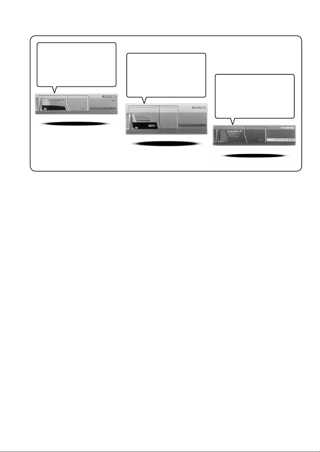
CD changer for CDA-7878.
Changeur CD pour CDA-7878.
Cambiador de CD para CDA-7878.
CD changer for CDA-7878.
Changeur CD pour CDA-7878.
Cambiador de CD para CDA-7878.
You cannot connect to CDA-7878.
Il est impossible de se raccorder au
CDA-7878.
No es posible conectarlo a CDA-7878.
CHA-S624
CHA-1214
CHM-S620
Alpine CD Changers Give You More!
More musical selections, more versatility, more convenience.
An Alpine CD Changer adds more musical choices to your sound system. All models except CHM-S620 can
be controlled from Alpine head units and deliver excellent sound quality. The CHA-S624 is a highperformance 6-disc changer with a new M DAC, Ai-NET compatibility, Optical Digital Output, 150 Disc
Title Memory and CD TEXT. The CHA-1214 Ai-NET model holds 12 discs, and the CHM-S620 M-Bus
model is a super-compact 6-disc changer.
Changeurs de CD Alpine : vous avez le choix!
Plus de sélections musicales, plus de souplesse, plus de confort.
Un changeur de CD Alpine permet d'augmenter la plage des sélections musicales de votre système embarqué.
Tous les modèles, à l'exception du CHM-S620, peuvent être contrôlés à partir des autoradios Alpine et offrent
une excellente qualité audio. Le modèle CHA-S624 est un changeur 6 disques ultra performant compatible
Ai-NET et équipé d'un convertisseur N/A standard, d'une sortie optique numérique, d'une mémoire d'une
capacité de 150 titres et de la fonction CD TEXT. Le modèle CHA-1214 Ai-NET peut contenir 12 disques.
Le modèle CHM-S620 M-Bus est un changeur 6 disques super compact.
¡Los cambiadores Alpine de CD le ofrecen más!
Más selecciones musicales, más versatilidad y más ventajas.
Un cambiador Alpine de CD añade más opciones musicales a su equipo de sonido. Todos los modelos,
excepto el CHM-S620, pueden controlarse desde las unidades principales de Alpine y proporcionar un sonido
de calidad excepcional. El modelo CHA-S624 es un cambiador de 6 discos de alto rendimiento con el nuevo
DAC "M" y compatibilidad con Ai-NET, salida digital óptica, memoria de títulos de 150 discos y TEXTO
CD. El modelo CHA-1214 Ai-NET admite 12 discos y el modelo CHM-S620 Bus-M es un cambiador de 6
discos y tamaño reducido.
Page 3

Contents
Operating Instructions
WARNING
WARNING.................................................. 2
CAUTION ................................................... 2
PRECAUTIONS ......................................... 2
Basic Operation
Detaching the Front Panel................................. 4
Attaching the Front Panel ................................. 4
Initial System Start-Up ..................................... 4
Turning Power On and Off ............................... 5
Display Angle Adjustment ................................ 5
Adjusting Volume/Balance (Between Left and
Right)/Fader (Between Front and Rear) ........ 5
Audio Mute Function ........................................ 5
Displaying Time................................................ 6
Setting Time ...................................................... 6
Adjusting Display Contrast ............................... 7
Subwoofer On and Off ...................................... 7
Switching the Phase of the Subwoofer Output ..... 8
Setting the Subwoofer Output........................... 8
Sound (Beep) Guide Function .......................... 9
Turning Mute Mode On/Off .............................. 9
Scroll Setting ................................................... 10
Setting the AUX Mode (V-Link) ..................... 11
Demonstration ................................................. 11
Defeat .............................................................. 12
Switching the Tuner Mode.............................. 12
Blackout Mode On and Off............................. 13
Switching the Display Modes ......................... 13
Setting the DHE/EQ for each Music Source .. 13
Displaying the Title/Text ................................. 14
Titling Discs/Stations ...................................... 15
Searching for Titled Discs/Titled Stations ...... 15
Erasing Disc Title/Station Title ....................... 15
Radio Operation
Manual Tuning ................................................ 16
Automatic Seek Tuning .................................. 16
Manual Storing of Station Presets .................. 17
Automatic Memory of Station Presets ............ 17
Tuning to Preset Stations ................................ 17
CD Player Operation
Opening and Closing the Movable display ..... 18
Playback .......................................................... 18
Music Sensor (Skip) ........................................ 19
Fast Forward and Backward ........................... 19
Repeat Play ..................................................... 19
M.I.X. (Random Play) .................................... 20
Scanning Programs ......................................... 20
Controlling CD Changer (Optional) ............... 21
Multi-Changer Selection ................................. 21
ENGLISH
MP3 Operation
Playing MP3 Files ........................................... 22
Music Sensor (Skip)........................................ 22
Fast Forward and Backward ........................... 23
Selecting Folders............................................. 23
File Search ...................................................... 23
Repeat Play ..................................................... 23
M.I.X. (Random Play) .................................... 23
Scanning Programs ......................................... 23
Setting the Range of MP3 File Selection ........ 24
About MP3 ...................................................... 24
Adjusting the Sound Operation
Selecting DHE Mode ...................................... 26
Equalizer Presets ............................................. 26
Adjusting and Storing the Equalizer Curve .... 27
Recalling the Stored Equalizer Curve ............. 27
Choosing the Listening Position Select (L.P.S.) ...
The Crossover/Time Correction...................... 28
Adjusting and Storing the Crossover/Time
Correction .................................................... 30
Recalling the Stored Crossover/Time Correction
Settings ............................................................
Customized Sound Database .......................... 32
27
31
XM Radio Operation
Receiving XM Channels with the XM Receiver
(Optional) .................................................... 33
Checking the XM Radio ID Number .............. 34
Storing XM Channel Presets........................... 34
Receiving Stored XM Channels...................... 35
Category Search .............................................. 35
Changing the Display...................................... 35
Remote Control Operation
Controls on Remote Control ........................... 36
Battery Replacement ....................................... 37
Operating the Audio Processor ....................... 38
Information
In Case of Difficulty ....................................... 40
Specifications .................................................. 43
Installation and Connections
Warning ........................................................... 44
Caution ............................................................ 44
Precautions ...................................................... 44
Installation ...................................................... 45
Connections .................................................... 46
LIMITED WARRANTY
1-EN
Page 4
WARNING
WARNING
This symbol means important instructions.
Failure to heed them can result in serious
injury or death.
DO NOT OPERATE ANY FUNCTION THAT TAKES
YOUR ATTENTION AWAY FROM SAFELY DRIVING
YOUR VEHICLE.
Any function that requires your prolonged attention
should only be performed after coming to a complete stop.
Always stop the vehicle in a safe location before
performing these functions. Failure to do so may result in
an accident.
KEEP THE VOLUME AT A LEVEL WHERE YOU CAN
STILL HEAR OUTSIDE NOISE WHILE DRIVING.
Failure to do so may result in an accident.
MINIMIZE DISPLAY VIEWING WHILE DRIVING.
Viewing the display may distract the driver from looking
ahead of the vehicle and cause an accident.
DO NOT DISASSEMBLE OR ALTER.
Doing so may result in an accident, fire or electric shock.
CAUTION
This symbol means important instructions.
Failure to heed them can result in injury or
material property damage.
HALT USE IMMEDIATELY IF A PROBLEM APPEARS.
Failure to do so may cause personal injury or damage to
the product. Return it to your authorized Alpine dealer or
the nearest Alpine Service Center for repairing.
DO NOT MIX NEW BATTERIES WITH OLD
BATTERIES. INSERT WITH THE CORRECT BATTERY
POLARITY.
When inserting the batteries, be sure to observe proper
polarity (+ and –) as instructed. Rupture or chemical
leakage from the battery may cause fire or personal injury.
KEEP FINGERS AWAY WHILE THE MOTORIZED
FRONT PANEL OR MOVING MONITOR IS IN
MOTION.
Failure to do so may result in personal injury or damage to
the product.
USE ONLY IN CARS WITH A 12 VOLT NEGATIVE
GROUND.
(Check with your dealer if you are not sure.) Failure to do
so may result in fire, etc.
KEEP SMALL OBJECTS SUCH AS BATTERIES OUT
OF THE REACH OF CHILDREN.
Swallowing them may result in serious injury. If
swallowed, consult a physician immediately.
USE THE CORRECT AMPERE RATING WHEN
REPLACING FUSES.
Failure to do so may result in fire or electric shock.
DO NOT BLOCK VENTS OR RADIATOR PANELS.
Doing so may cause heat to build up inside and may result
in fire.
USE THIS PRODUCT FOR MOBILE 12V
APPLICATIONS.
Use for other than its designed application may result in
fire, electric shock or other injury.
DO NOT PLACE HANDS, FINGERS OR FOREIGN
OBJECTS IN INSERTION SLOTS OR GAPS.
Doing so may result in personal injury or damage to the
product.
PRECAUTIONS
Temperature
Be sure the temperature inside the vehicle is between
+60°C (+140°F) and –10°C (+14°F) before turning your
unit on.
Moisture Condensation
You may notice the CD playback sound wavering due to
condensation. If this happens, remove the disc from the
player and wait about an hour for the moisture to
evaporate.
Damaged Disc
Do not attempt to play cracked, warped, or damaged
discs. Playing a bad disc could severely damage the
playback mechanism.
Maintenance
If you have problems, do not attempt to repair the unit
yourself. Return it to your Alpine dealer or the nearest
Alpine Service Station for servicing.
2-EN
Page 5

Never Attempt the Following
Do not grip or pull out the disc while it is being pulled
back into the player by the automatic reloading
mechanism.
Do not attempt to insert a disc into the unit when the unit
power is off.
Inserting Discs
Your player accepts only one disc at a time for playback.
Do not attempt to load more than one disc.
Make sure the label side is facing up when you insert the
disc. Your player will automatically eject any disc that is
inserted incorrectly. If the player continues to eject a
correctly inserted disc, push the RESET switch with a
pointed object such as a ballpoint pen.
Playing a disc while driving on a very bumpy road may
result in skips, but this will not scratch the disc or damage
the player.
New Discs
As a protective measure to prevent the CD from jamming,
the CD player will automatically eject discs with irregular
surfaces or inserted incorrectly. When a new disc is
inserted into the player and ejected after initial loading,
using your finger, feel around the inside of the centre hole
and outside edge of the disc. If you feel any small bumps
or irregularities, this could inhibit proper loading of the
disc. To remove the bumps, rub the inside edge of the hole
and outside edge of the disc with a ballpoint pen or other
such instrument, then insert the disc again.
Installation Location
Make sure the CDA-7878 will not be installed in a
location subjected to:
• Direct sun and heat
• High humidity and water
• Excessive dust
• Excessive vibrations
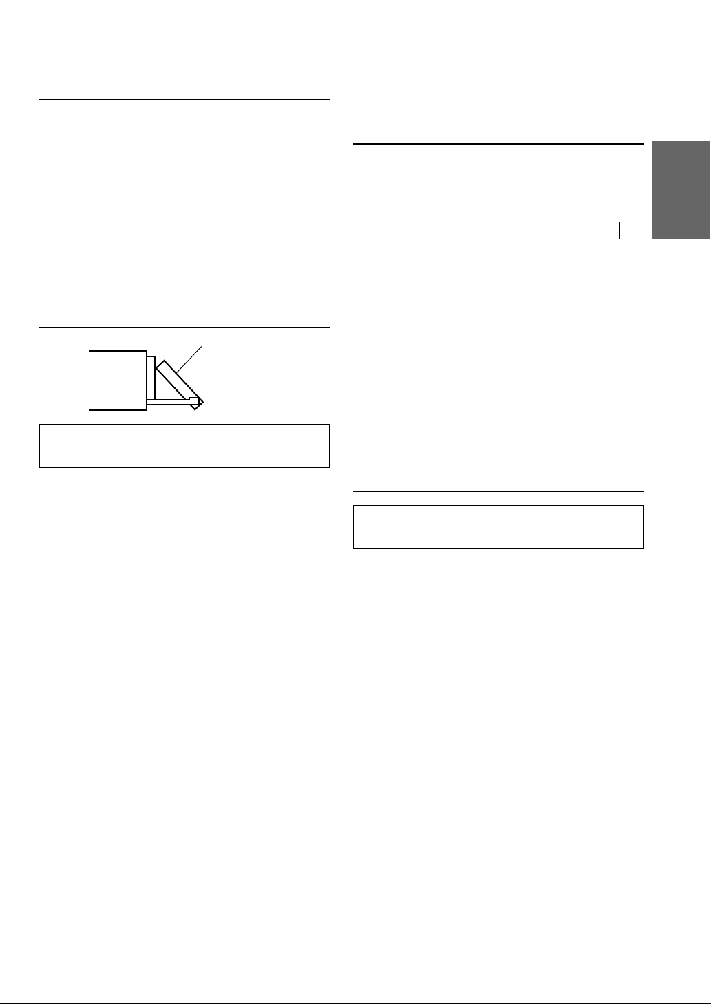
Correct Handling
Do not drop the disc while handling. Hold the disc so you
will not leave fingerprints on the surface. Do not affix
tape, paper, or gummed labels to the disc. Do not write on
the disc.
CORRECT
INCORRECT CORRECT
Disc Cleaning
Fingerprints, dust, or soil on the surface of the disc could
cause the CD player to skip. For routine cleaning, wipe
the playing surface with a clean, soft cloth from the centre
of the disc to the outer edge. If the surface is heavily
soiled, dampen a clean, soft cloth in a solution of mild
neutral detergent before cleaning the disc.
Center
Hole
Bumps
Center
Hole
New
Disc
Outside
(Bumps)
Irregular Shaped Discs
Be sure to use round shape discs only for this unit and
never use any special shape discs.
Use of special shape discs may cause damage to the
mechanism.
Disc Accessories
There are various accessories available on the market for
protecting the disc surface and improving sound quality.
However, most of them will influence the thickness and/or
diameter of the disc. Using such accessories can cause the
disc to be out of standard specifications and may create
operational problems. We recommend not using these
accessories on discs played in Alpine CD players.
Disc StabilizerTransparent Sheet
3-EN
Page 6
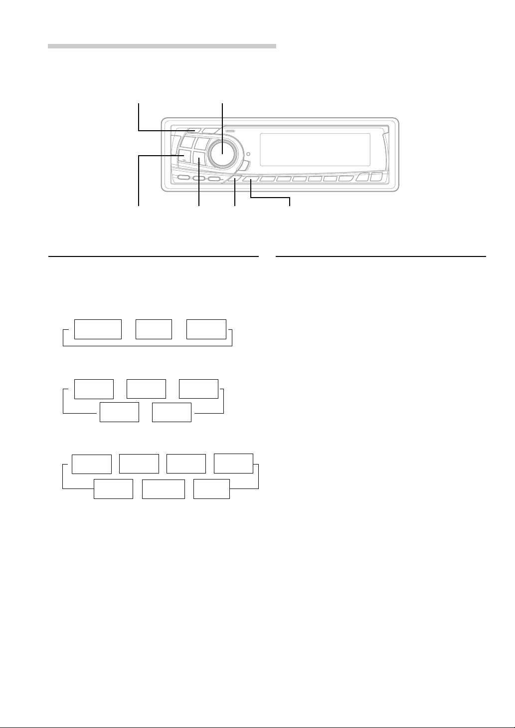
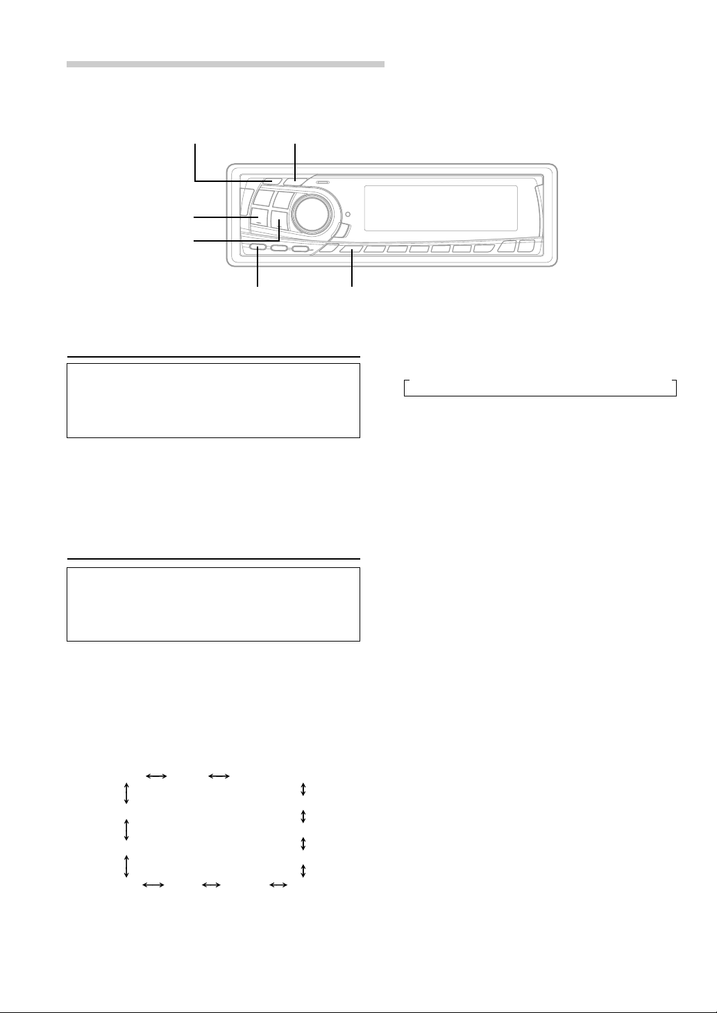
Basic Operation
1
POWER
MODE/Audio Control
RESET MUTE
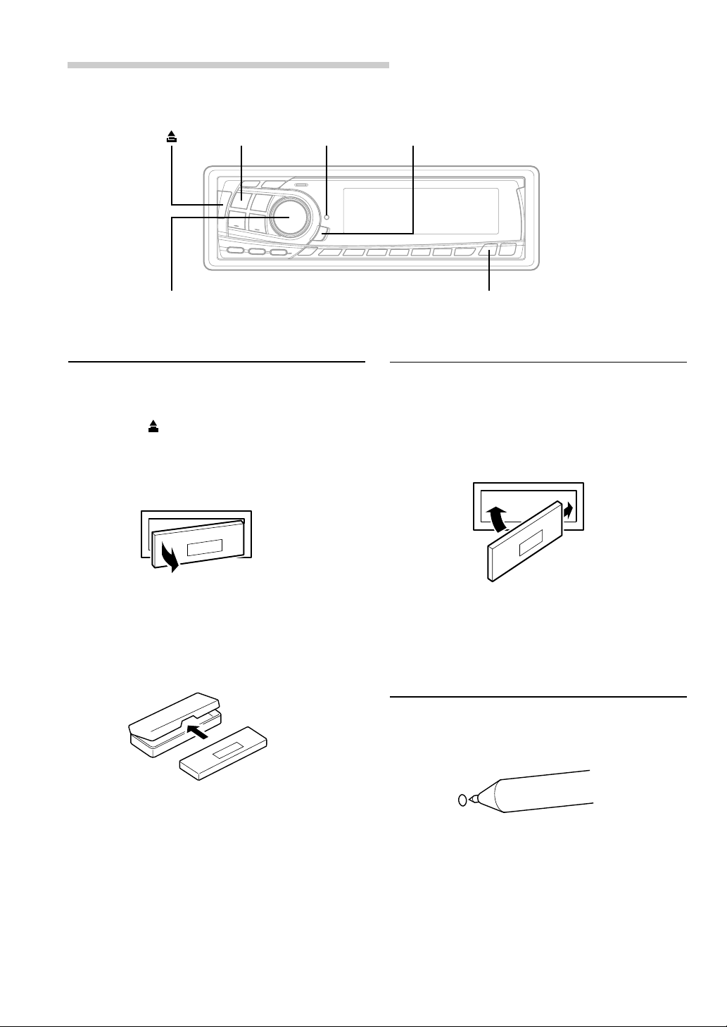
Detaching the Front Panel
1 Press and hold the POWER button for at least 2
seconds to turn off the power.
2 Press the (Release) button at upper left side
until the front panel pops out.
3 Grasp the left side of the front panel and pull it
out.
8
ANGLE
9
Attaching the Front Panel
1 First, insert the right side of the front panel into
the main unit. Align the groove on the front panel
with the projections on the main unit.
2 Push the left side of the front panel until it locks
firmly into the main unit.
2
1
NOTES
• The front panel may become hot in normal usage
(especially the connector terminals on the back of the
front panel.) This is not a malfunction.
• To protect the front panel, place it in the supplied
carrying case.
4-EN
NOTE
Before attaching the front panel, make sure that there is
no dirt or dust on the connector terminals and no foreign
object between the front panel and the main unit.
Initial System Start-Up
Immediately after installing or applying power to the
unit, it should be initialized. Press the RESET switch
with a ballpoint pen or any other pointed object.
Page 7
Turning Power On and Off
1 Press the POWER button to turn on the unit.
NOTE
The unit can be turned on by pressing any other button
except the c or CLK/TITLE button.
The volume level gradually increases to the
previous level you were listening to before the
unit was turned off. Press and hold the POWER
button for at least 2 seconds to turn off the unit.
NOTE
The first time power is turned on, the volume will start
from level 12 and the unit will be in the tuner mode.
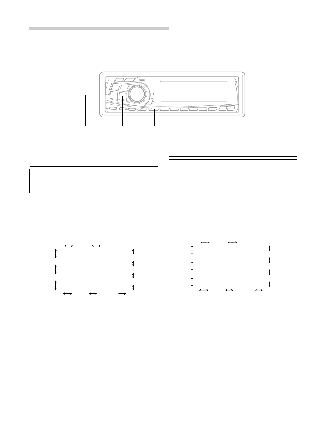
Display Angle Adjustment
Movable display
The movable display may be adjusted to 3
different angles depending upon user preference.
Adjusting Volume/Balance
(Between Left and Right)/Fader
(Between Front and Rear)
1 Press the MODE button repeatedly to choose
the desired mode.
Each press changes the modes as follows:
→ BALANCE → FADER → VOLUME
NOTES
• If the MODE button is not pressed within 5 seconds
after selecting the BALANCE or FADER mode, the
unit automatically returns to the VOLUME mode.
• When the subwoofer mode is ON, its level may also be
adjusted.
• When setting the 3WAY/2WAY switch (page 47) to
3WAY, you cannot adjust the FADER mode.
2 Rotate the Audio Control knob until the desired
sound is obtained in each mode.
NOTE
Depending on the connected devices, some functions and
display indications do not work.
1 Press the ANGLE 89 button to adjust the angle
of the movable display.
NOTES
• The display will close a half minute after the ignition
key is turned to the OFF position.
• The adjusted angle of the display is stored in memory.
There is no need to re-adjust the angle when the power
is turned back on.
CAUTION
Keep hands (or any other object) away from the display
while it is opening or closing to avoid damage or injury.
The back of the movable display will get very warm
under normal operating conditions. This is not a
malfunction. Do not touch.
Audio Mute Function
Activating this function will instantly lower the
volume level by 20 dB.
1 Press the MUTE button to activate the MUTE
mode. The audio level will decrease by about
20 dB.
Pressing the MUTE button again will bring the
audio back to its previous level.
5-EN
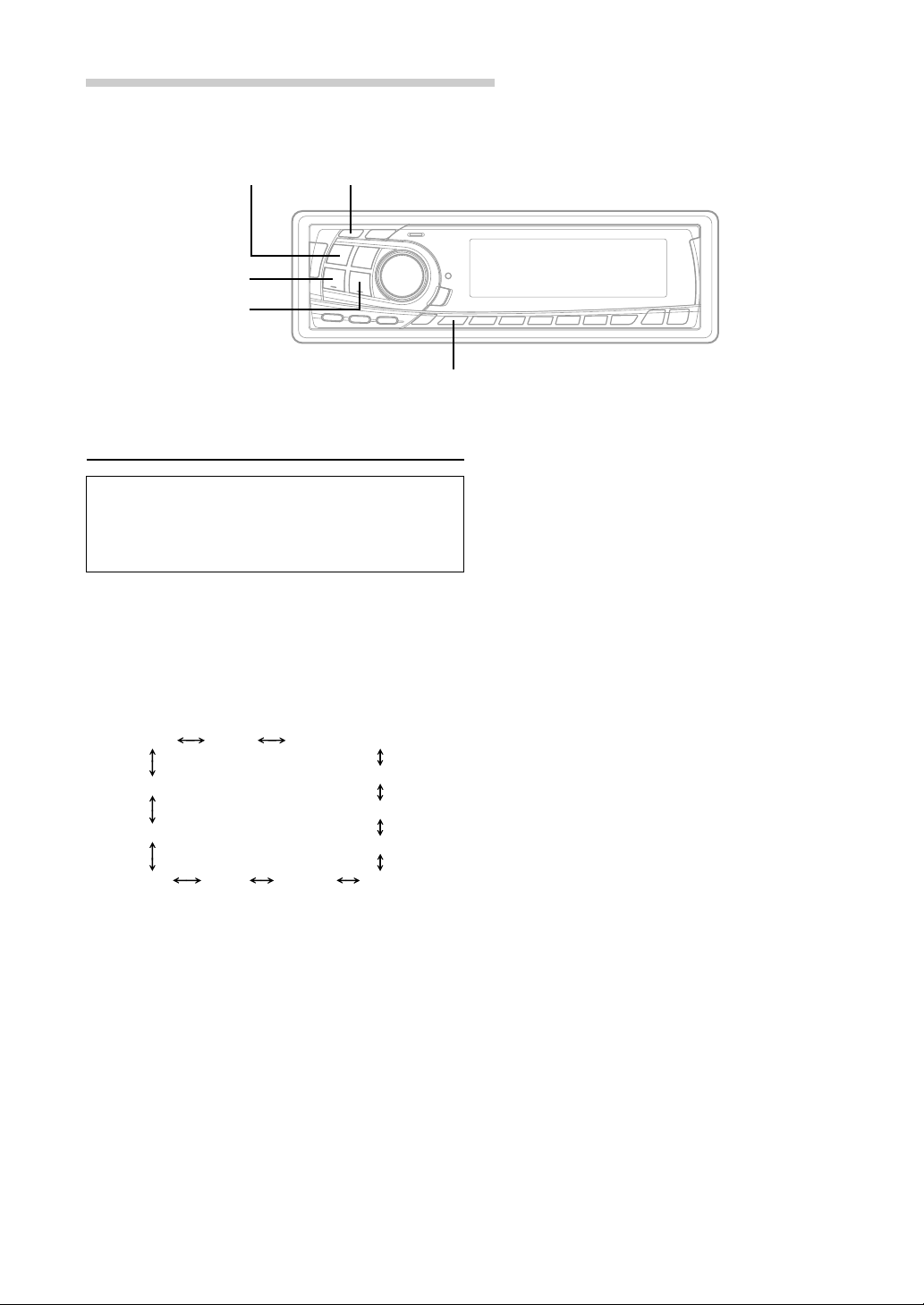
Page 8
Basic Operation
TUNE
g DN f UP
MODE/Audio Control
Displaying Time
1 Press the CLK (clock) button repeatedly until the
time is displayed.
Each press changes the modes as follows:
Radio mode
→
Radio frequency
CD Player/Changer modes
Playing time
→
mode
TITLE mode
MP3 modes
Playing time
→→→
mode
TITLE mode
Clock priority
→ →
mode
Clock priority
→→
mode
TRACK
←
TEXT mode
Clock priority
mode
Frame
←
display mode
TITLE mode
DISC TEXT
mode
←
Folder name
mode
ID3 tag
←
mode
→
File name
mode
SETUPCLK
Setting Time
1 In the Clock priority mode, press and hold the
CLK (clock) button for at least 2 seconds while
the time is displayed. The time indication will
blink.
2 Rotate the Audio Control knob to adjust the
hours while the time indication is blinking.
3 When the hours has been adjusted, press the
MODE button.
4 Rotate the Audio Control knob to adjust the
minutes while the time indication is blinking. The
time is automatically set 5 seconds after the
minute adjustment. The time can also be
manually set by pressing the MODE button.
NOTE
Selecting any tuner or CD function while in the clock
priority mode will interrupt the time display
momentarily. The function selected will be displayed for
about 5 seconds before the time returns to the display.
6-EN
Page 9

Adjusting Display Contrast
Subwoofer On and Off
You can adjust the display contrast for better
visibility.
1 Press and hold the SETUP button for at least 2
seconds.
2 Press the f UP button repeatedly to select
“CONTRAST.”
Each press of the f UP button changes the
modes as shown:
TUNER SUB-W
DEMO
CONTRAST
AUX MUTE SCROLL BEEP
∗ Displayed when you set SUB-W to ON.
NOTE
If you press the g DN button, the display scrolls in
reverse sequence.
3
Press the TUNE button to adjust the contrast of
the display. You can adjust in a range of -5 and
+5.
The initial setting at the factory is "0."
SUB-W (switching phase)
SUB-W STEREO/MONO
SRC DHE
DISC/FOLDER
4 Press the SETUP button to set the selected
mode.
1 Press and hold the SETUP button for at least 2
seconds.
2 Press the f UP button repeatedly to select
“SUB-W.”
Each press of the f UP button changes the
modes as shown:
TUNER SUB-W
DEMO
∗
∗
CONTRAST
AUX MUTE SCROLL BEEP
∗ Displayed when you set SUB-W to ON.
NOTE
If you press the g DN button, the display scrolls in
reverse sequence.
SUB-W (switching phase)
SUB-W STEREO/MONO
SRC DHE
DISC/FOLDER
3 Press the TUNE button to toggle mode between
SUB-W ON and SUB-W OFF.
4 Press the SETUP button after setting the SUB-W
ON.
5 Press the MODE button repeatedly to select the
SUB-W mode.
→ SUB-W → BALANCE
VOLUME ← FADER ←
∗
∗
6 Rotate Audio Control knob until the desired
sound is obtained in each mode.
7-EN
Page 10
Basic Operation
TUNE
g DN f UP
SETUP
Switching the Phase of the
Subwoofer Output
You can switch the phase of the subwoofer output
to NORMAL 0˚ or REVERSE 180˚.
To select the desired phase.
1 Press and hold the SETUP button for at least 2
seconds.
2 Press the fUP button to select “Switching the
phase of the SUB-W (SUB-W NORMAL or
REVERSE) mode.”
TUNER SUB-W
DEMO
CONTRAST
AUX MUTE SCROLL BEEP
∗ Displayed when you set SUB-W to ON.
NOTE
If you press the g DN button, the display scrolls in
reverse sequence.
SUB-W (switching phase)
SUB-W STEREO/MONO
SRC DHE
DISC/FOLDER
Setting the Subwoofer Output
You can set the subwoofer output to stereo or
monaural.
Make sure to set the correct output for your
subwoofer type.
1 Press and hold the SETUP button for at least 2
seconds.
2 Press the fUP button to select “Switching the
SUB-W monaural/Stereo (SUB-W STEREO or
MONO) mode.”
∗
∗
TUNER SUB-W
DEMO
CONTRAST
AUX MUTE SCROLL BEEP
∗ Displayed when you set SUB-W to ON.
NOTE
If you press the g DN button, the display scrolls in
reverse sequence.
SUB-W (switching phase)
SUB-W STEREO/MONO
SRC DHE
DISC/FOLDER
∗
∗
3 Press the TUNE button to select NORMAL (0˚) or
REVERSE (180˚).
NOTE
The initial setting at the factory is SUB-W NORMAL.
4 Press the SETUP button to set the selected
mode.
8-EN
3 Press the TUNE button to select SUB-W
STEREO or MONO.
SUB-W STEREO:
Subwoofer stereo (L/R) output
SUB-W MONO:
Subwoofer monaural output.
NOTE
The initial setting at the factory is SUB-W STEREO.
4 Press the SETUP button to set the selected
mode.
Page 11

Sound (Beep) Guide Function
Turning Mute Mode On/Off
This function will give audible feedback with
varying tones depending upon the button
pressed.
1 Press and hold the SETUP button for at least 2
seconds.
2 Press the f UP button repeatedly to select
“BEEP.”
Each press of the f UP button changes the
modes as shown:
TUNER SUB-W
DEMO
CONTRAST
AUX MUTE SCROLL BEEP
∗ Displayed when you set SUB-W to ON.
NOTE
If you press the g DN button, the display scrolls in
reverse sequence.
SUB-W (switching phase)
SUB-W STEREO/MONO
SRC DHE
DISC/FOLDER
3 Press the TUNE button to toggle the mode
between BEEP ON and BEEP OFF.
NOTE
The initial setting at the factory is BEEP ON.
4 Press the SETUP button to set the selected
mode.
If a device having the interrupt feature is
connected, audio will be automatically muted
whenever the interrupt signal is received from the
device. This function can be turned ON or OFF
from the head unit by following procedure below.
1 Press and hold the SETUP button for at least 2
seconds.
2 Press the f UP button to select the MUTE
mode. Each press changes the modes as shown:
∗
∗
TUNER SUB-W
DEMO
CONTRAST
AUX MUTE SCROLL BEEP
∗ Displayed when you set SUB-W to ON.
NOTE
If you press the g DN button, the display scrolls in
reverse sequence.
SUB-W (switching phase)
SUB-W STEREO/MONO
DISC/FOLDER
3 Press the TUNE button to turn on or off the
MUTE mode.
Each press toggles between the MUTE ON and
OFF modes.
NOTE
The initial setting at the factory is “MUTE ON.”
4 Press the SETUP button again to return to
normal operation.
∗
∗
SRC DHE
9-EN
Page 12
Basic Operation
SOURCE TUNE
g DN
f UP
SETUP
Scroll Setting
This CD player can scroll the disc and track
names recorded on CD-TEXT discs, as well as
the text information of MP3 files, folder names,
and ID3 tags.
1 Press and hold the SETUP button for at least 2
seconds.
2 Press the f UP button repeatedly to select
“SCROLL.”
Each press of the f UP button changes the
modes as shown:
TUNER SUB-W
DEMO
CONTRAST
AUX MUTE SCROLL BEEP
∗ Displayed when you set SUB-W to ON.
NOTE
If you press the g DN button, the display scrolls in
reverse sequence.
SUB-W (switching phase)
SUB-W STEREO/MONO
SRC DHE
DISC/FOLDER
3 Press the TUNE button to toggle mode between
SCROLL AUTO and MANU.
• SCROLL AUTO: the CD text information, the
text information of folder and file names, and
the ID3 tags are scrolled automatically.
• SCROLL MANU: the display is scrolled only
when a disc is loaded or when a track is changed
and the text information exceeds 12 digits.
4 When the setting is completed, press the SETUP
button to return to the normal mode.
NOTES
• Initial mode is “SCROLL MANU.”
• The unit scrolls CD text names, folder names, file
∗
∗
names or ID3 tag display. The disc titles input
manually (refer to page 15) cannot be scrolled.
10-EN
Page 13
Setting the AUX Mode (V-Link)
Demonstration
You can input TV/video sound by connecting an
optional Ai-NET/RCA Interface cable (KCA-121B)
or Versatile Link Terminal (KCA-410C) to this
component.
1 Press and hold the SETUP button for at least 2
seconds.
2 Press the f UP button repeatedly to select
“AUX.”
Each press of the f UP button changes the
modes as shown:
TUNER SUB-W
DEMO
CONTRAST
(AUX Mode Display Setting∗∗)
AUX
∗ Displayed when you set SUB-W to ON.
∗∗ Displayed when you set AUX IN to ON.
NOTE
If you press the g DN button, the display scrolls in
reverse sequence.
MUTE SCROLL BEEP
SUB-W (switching phase)
SUB-W STEREO/MONO
SRC DHE
DISC/FOLDER
3 Press the TUNE button to toggle the mode
between AUX IN ON and AUX IN OFF.
NOTES
• The initial setting at the factory is AUX IN OFF.
• You can set the AUX mode display by pressing the
g DN or f UP button after AUX IN ON is set,
select the AUX mode display setting, and then press
the TUNE button.
• When connecting the KCA-410C, you can set two AUX
mode displays.
This unit has a Demonstration feature which
simulates the display functions.
1 Press and hold the SETUP button for at least 2
seconds.
2 Press the f UP button to select the DEMO
mode. Each press changes the modes as shown:
TUNER SUB-W
DEMO
∗
∗
CONTRAST
AUX MUTE SCROLL BEEP
∗ Displayed when you set SUB-W to ON.
NOTE
If you press the g DN button, the display scrolls in
reverse sequence.
SUB-W (switching phase)
SUB-W STEREO/MONO
DISC/FOLDER
3 Press the TUNE button to turn on or off the
DEMO mode.
Each press toggles between DEMO ON and
DEMO OFF.
If no button is pressed for 30 seconds, the
DEMO mode activates.
NOTES
• The initial setting at the factory is “DEMO OFF.”
• To quit DEMO mode, set to “DEMO OFF.”
4 Press the SETUP button again to return to
normal operation.
∗
∗
SRC DHE
4 Press the SETUP button to return to normal
mode.
5 To adjust the volume, etc., first press the
SOURCE button and select the AUX mode, then
make the necessary adjustment.
NOTE
When using the Versatile Link Terminal (KCA-410C), you
can connect two external inputs. To select the mode,
press the BAND button on the unit.
11-EN
Page 14
Basic Operation
TUNE
g DN
f UP
DISP/B.OUT
DEFEAT
SETUP
Defeat
Use the DEFEAT button to return the previously
adjusted settings of DHE, EQ, and CSD
(Customized Sound Database) to the factory
default settings.
1 Press and hold the DEFEAT button for at least 2
seconds to turn Defeat on.
To cancel Defeat, press and hold the DEFEAT
button again for at least 2 seconds.
Switching the Tuner Mode
3 Press the TUNE button to switch the TUNER
mode.
→
TUNER HI-FI
•
TUNER
•
TUNER
•
TUNER
NOTES
• The initial setting at the factory is "NORMAL."
This is the best compromise between sound quality and
noise immunity.
• If you switch the tuner to HI-FI mode and find the
station is too noisy, we recommend you change back to
the NORMAL mode.
→
TUNER NORMAL
NORMAL : Standard setting
HI-FI :
STABLE : Noiseless priority setting
Sound quality priority setting
→
TUNER STABLE
The CDA-7878 incorporates the MAX TUNE SQ
for the highest quality tuner audio. Moreover, you
can choose between 3 settings to suit your own
personal sound preferences and usage.
1 Press and hold the SETUP button for at least 2
seconds.
2 Press the f UP button repeatedly to select
"TUNER."
Each press of the f UP button changes the
modes as shown:
TUNER SUB-W
DEMO
CONTRAST
AUX MUTE SCROLL BEEP
∗ Displayed when you set SUB-W to ON.
NOTE
If you press the g DN button, the display scrolls in
reverse sequence.
SUB-W (switching phase)
SUB-W STEREO/MONO
SRC DHE
DISC/FOLDER
4 When the setting is completed, press the SETUP
button to return to the normal mode.
∗
∗
12-EN
Page 15

Blackout Mode On and Off
When the Blackout mode is turned on, the display
will turn off to reduce power consumption.
This additional power enhances the sound quality.
1 Press and hold the B.OUT button for at least 2
seconds to start the blackout mode. By doing so
the display will turn off.
NOTE
If any button on the unit is pressed during the blackout
mode, the function will be displayed for 5 seconds to
show the operation before returning to Blackout mode.
To cancel the blackout mode, press and hold the
B.OUT button for at least 2 seconds.
Setting the DHE/EQ for each Music
Source
You can set the DHE/EQ independently for each
music source (e.g., radio, CD, MP3, etc.).
1 Press and hold the SETUP button for at least 2
seconds.
2 Press the f UP button repeatedly to select
"SRC DHE."
Each press of the f UP button changes the
modes as shown:
TUNER SUB-W
SUB-W (switching phase)
∗
Switching the Display Modes
You can select the display pattern mode from
three display patterns. You can also deactivate the
display.
1 Press the DISP (DISPLAY) button to select the
desired Display pattern mode.
Each press changes the display patterns.
→ Pattern1 → Pattern2 → Pattern3 → Display OFF
DEMO
CONTRAST
AUX MUTE SCROLL BEEP
∗ Displayed when you set SUB-W to ON.
NOTE
If you press the g DN button, the display scrolls in
reverse sequence.
SUB-W STEREO/MONO
SRC DHE
DISC/FOLDER
3 Press the TUNE button to toggle the mode
between SRC DHE ON and SRC DHE OFF.
SRC DHE ON:
You can set the DHE/EQ independently for each
music source (e.g., radio, CD, MP3, etc.).
SRC DHE OFF:
You can set the same DHE/EQ for all the music
sources at the same time.
NOTE
The initial setting at the factory is SRC DHE OFF.
4 Press the SETUP button to set the selected
mode.
∗
13-EN
Page 16

Basic Operation
BAND/
-/J
g DN f UP TITLE
T.S.M.
MODE/
Audio Control
Displaying the Title/Text
It is possible to display the CD/Station title if the
title has been previously inputted. For details, see
“
Titling Disc/Stations” (page 15). Text information,
such as the disc name and the track name, will be
displayed if playing a CD text compatible disc. It is
also possible to display the folder name, the file
name, and the ID3 tag, etc. while playing MP3 files.
1 Press the TITLE button.
The mode will change every time the button is
pressed.
About “Title” and “Text”
Title: With this device, it is possible to input the CD/
Station name (refer to page 15). This inputted
name is referred to as a “title.”
Text: Text compatible CDs contain text information
such as the disc name and track name. Such
text information is referred to as “text.”
Radio mode:
FREQUENCY DISPLAY
CLOCK DISPLAY
CD/Changer mode:
ELAPSED TIME DISPLAY
CLOCK DISPLAY
TEXT DISPLAY (DISC NAME)
TEXT DISPLAY (TRACK NAME)
↓
↓
↓
TITLE DISPLAY
↓
↓
↓
↓
↓
TITLE DISPLAY
∗1
∗1
MP3 mode:
ELAPSED TIME DISPLAY
FOLDER NAME DISPLAY
FILE NAME DISPLAY
ID3 TAG DISPLAY
FRAME DISPLAY
∗1
Displayed during playback of a disc with CD
↓
↓
CLOCK DISPLAY
↓
↓
↓
↓
↓
TITLE DISPLAY
∗2
∗3
Text. “NO TEXT” will be displayed when the
CD contains no Text data.
∗2
If an MP3 file contains ID3 tag information, all
the ID3 tag information is displayed (e.g.,
track name, artist name, and album name).
No other information is displayed.
“NO TAG” will be displayed when an MP3 file
contains no ID3 tag information.
∗3
The recording sampling rate and bit rate of
the MP3 file are displayed.
NOTES
• Some characters may not be displayed correctly with
this device, depending on the character type.
• The CD changer must also be CD Text compatible for
the Text information to be displayed.
• When the Scroll Setting (refer to page 10) is set to
“SCROLL MANU”, press and hold the TITLE button
for at least 2 seconds to scroll the Text information
only once (TEXT DISPLAY, FOLDER NAME
DISPLAY, FILE NAME DISPLAY or ID3 TAG
DISPLAY mode).
• “No Support” is displayed when the desired text
information cannot be displayed on this unit.
• If the title was not previously input, “------------” is
displayed.
14-EN
Page 17

Titling Discs/Stations
It is possible to title your favorite CD's or radio
stations.
1 Press the TITLE button and select the title
display mode.
For details, see “Displaying the Title/Text” (page
14).
2 Press and hold the TITLE button for at least 2
seconds. The first character will blink.
3 Press the BAND button to select the characters/
symbols.
→ Upper case → Lower case → Numeral/Symbol
4 Rotate the Audio Control knob to select the
desired letter/numeral/symbol available for
naming. (“A” for example).
5 Press the MODE button to store the first
character. The first character will stop blinking
and the display will automatically advance to the
next character. When that character begins to
blink, you may choose the next letter or symbol
of your title.
6 Repeat the steps 3 to 5 above to complete the
titling. Pressing the Audio Control button after
entering the 12th character, automatically stores
the title into memory.
When entering a title of less than 12 characters
(for example, 3 character title):
After entering 3 characters to complete your title,
the 4th character space will be blinking. Go to
step 7 to complete the title.
Searching for Titled Discs/Titled
Stations
If a CD/Station is titled, you can do a search for it.
(To title CDs or stations, refer to “Titling Discs/
Stations” on this page.)
1 When the unit is in radio or CD Changer mode,
press and hold the T.S.M. button for at least 2
seconds. The title blinks in the display.
2 Press the g DN or f UP button to select
the desired disc title from the CD changer, or the
desired station title.
3 Press the T.S.M. button to play the selected disc
or station.
The unit will automatically search for the disc or
station and begin play.
NOTE
This function cannot be performed when using a multichanger switching device.
Erasing Disc Title/Station Title
1 Press the TITLE button to select the titling mode.
Then, press and hold the button for at least 2
seconds.
2 Press and hold the -/J button for at least 2
seconds to activate the title scanning mode. The
title in the display will blink.
3 Press the g DN or f UP button repeatedly
until the title you want to erase is displayed.
4 Press and hold the -/J button for at least 2
seconds to erase the title displayed.
7 Press and hold the TITLE button for at least 2
seconds to record the title.
NOTES
• You can enter 24 radio station titles and 24 CD titles
on this unit. If you try to store beyond the limit, the
display will show “FULL DATA.” At this point, no
more titles can be stored.
• The CD Changer title length or memory capacity
varies depending upon the model being used.
• To input a new title, one of the previously inputted
titles must first be deleted.
• When you want to erase a title, enter the “
into all spaces.
• The operations described in steps 3 to 6 must be made
within 10 seconds. The input mode will be cancelled if
no action is taken for over 10 seconds.
• Removing power from the unit may delete these titles.
Use caution when manipulating the power cord.
” symbol
5 Press and hold the TITLE button for at least 2
seconds to cancel the title erasing mode.
NOTE
You cannot erase CD-TEXT.
15-EN
Page 18

Radio Operation
SOURCE BAND
g DN f UP
TUNE/A.ME Preset buttons (1 through 6)
Manual Tuning
1 Press the SOURCE button until a radio
frequency appears in the display.
2 Press the BAND button repeatedly until the
desired radio band is displayed.
Each press changes the band:
→ FM1 → FM2 → AM
3 Press the TUNE button repeatedly until “DX
SEEK” and “SEEK” disappear from the display.
NOTE
The initial mode is DX SEEK.
4 Press the g DN or f UP button to move
downward or upward one step respectively until
the desired station frequency is displayed.
NOTE
The ST indicator appears on the display when a Stereo
FM station is tuned in.
Automatic Seek Tuning
1 Press the SOURCE button until a radio
frequency appears in the display.
2 Press the BAND button repeatedly until the
desired radio band is displayed.
Each press changes the band:
→ FM1 → FM2 → AM
3 Press the TUNE button to illuminate the DX and
SEEK indicators in the display.
With the DX (Distance) mode activated, both
strong and weak stations will be tuned in the
Auto-Seek operation.
Press again to return to the local mode. The DX
indicator will turn off and the SEEK indicator will
remain illuminated. Now, only strong stations will
be tuned.
4 Press the g DN or f UP button to
automatically seek for a station downward or
upward respectively.
The unit will stop at the next station it finds.
Press the same button again to seek the next
station.
16-EN
Page 19

Manual Storing of Station Presets
Tuning to Preset Stations
1 Select the radio band and tune in a desired radio
station you wish to store in the preset memory.
2 Press and hold any one of the Preset buttons
(1 through 6) for at least 2 seconds until the
station frequency on the display blinks.
3 Press the Preset button into which you wish to
store the station while the frequency display is
blinking (within 5 seconds).
The display stops blinking once the station has
been memorized. The display shows the band,
preset No. with a triangle (9) and station
frequency memorized.
4 Repeat the procedure to store up to 5 other
stations onto the same band.
To use this procedure for other bands, simply
select the band desired and repeat the
procedure.
A total of 18 stations can be stored in the preset
memory (6 stations for each band; FM1, FM2
and AM).
NOTE
If you store a station in a preset memory which already
has a station, the current station will be cleared and
replaced with the new station.
1 Press the SOURCE button to select the radio
mode.
2 Press the BAND button repeatedly until the
desired band is displayed.
3 Press the station Preset button that has your
desired radio station in memory.
The display shows the band, preset number with
a triangle and frequency of the station selected.
Automatic Memory of Station
Presets
1 Press the SOURCE button to select the radio
mode.
2 Press the BAND button repeatedly until the
desired radio band is displayed.
3 Press and hold the A. ME button for at least 2
seconds.
The frequency on the display continues to
change while the automatic memory is in
progress. The tuner will automatically seek and
store 6 strong stations in the selected band.
They will be stored into buttons 1 to 6 in order of
signal strength.
When the automatic memory has been
completed, the tuner goes to the station stored in
the preset location No. 1.
NOTE
If no stations are stored, the tuner will return to the
original station you were listening to before the auto
memory procedure began.
17-EN
Page 20

CD Player Operation
SOURCE
-/J
f UP g DN REPEAT
Opening and Closing the Movable
display
1 Press the c button.
The movable display will open.
To close the movable display, press the c button
again.
The movable display will close.
NOTES
• Do not apply shock to the movable display when it is
open as it may result in malfunction of the unit.
• The display may be dim during low temperatures and
immediately after turning on the power. The brightness
will return to normal as time elapses.
• The display will stop at the set angle when closing.
CAUTION
Keep hands (or any other object) away from the display
while it is opening or closing to avoid damage or injury.
The back of the movable display will get very warm
under normal operating conditions. This is not a
malfunction. Do not touch.
c
Playback
1 Press the c button.
The movable display will open.
Insert a disc with the label side facing up.
2 Insert a disc with the label side facing up.
The disc will be pulled into the unit automatically.
The movable display will close and playback will
begin.
When a disc is already inserted, press the
SOURCE button to switch to the CD mode.
The mode will change every time the button is
pressed.
→ TUNER → CD → CD CHANGER∗
(∗ Only when the CD changer is connected)
3 To pause playback, press the -/J button.
Pressing the -/J button again will resume playback.
18-EN
4 To eject the disc, press the c button.
NOTE
If the CD does not eject, press c button again for more
than 2 seconds with the movable display open.
Page 21

About the usable discs.
We recommend using only compact discs
containing the marks shown below.
You can play CD-Rs (CD-Recordable)/CD-RWs
(CD-ReWritable) for audio use on this unit. You
can also play CD-Rs/CD-RWs containing MP3
formatted audio files.
• Some of the following CDs may not play on this
unit:
Flawed CDs, CDs with fingerprints, CDs
exposed to extreme temperatures or sunlight
(e.g., left in the car or this unit), CDs recorded
under unstable conditions, CDs on which a
recording failed a re-recording was attempted.
• Use discs with MP3 files written in the format
compliant with ISO 9660 level 1 or level 2. For
details, see page 25.
Music Sensor (Skip)
1 Momentarily press the g DN button once
during CD play to return to the beginning of the
current track. If you wish to access the beginning
of a track further back, repeatedly press until
you reach the desired track.
Press the f UP button once to advance to
the beginning of the next track. If you wish to
access the beginning of a track further ahead,
press repeatedly until the desired track is
reached.
NOTE
The music sensor feature is functional in the play or
pause mode.
Fast Forward and Backward
1 Press and hold the g DN or f UP button
to quickly move backward or forward until you
reach the desired section of the track.
On handling Compact Discs (CD/CD-R/
CD-RW)
• Do not touch the surface.
• Do not expose the disc to direct sunlight.
• Do not affix stickers or labels and do not write
on the surface.
• Clean the disc when it is dusty.
• Make sure that there are no bumps around the
disc.
• Do not use commercially available disc
accessories.
Do not leave the disc in the car or the unit for
a long time. Never expose the disc to direct
sunlight. Heat and humidity may damage the CD
and you may not be able to play it again.
Repeat Play
1 Press the REPEAT button to play back
repeatedly the track being played.
The track will be played repeatedly.
Press the REPEAT button again and select OFF
to deactivate the repeat play.
NOTES
• If a CD Changer is connected and the RPT-ALL mode
is selected, the unit repeatedly plays back all tracks on
the disc selected.
→ RPT- → RPT- ALL → (off)
• In case a 6-disc CD changer is connected:
In CD changer mode, press the “F” button to
illuminate the
within 5 seconds.
• In case a 12-disc CD changer is connected:
In changer mode, press the “F” button twice to
illuminate the
within 5 seconds.
indicator and go to step 1
indicator and go to step 1
19-EN
Page 22

CD Player Operation
SOURCE
F
M.I.X. (Random Play)
1 Press the M.I.X. button in the play or pause mode.
The tracks on the disc will be played back in a
random sequence. After all the tracks on the disc
have been played back once, the player will
begin a new random sequence play until the
M.I.X. mode is cancelled.
To cancel M.I.X. play, press the M.I.X. button
again to turn off the M.I.X.
NOTES
• If a CD Changer equipped with the ALL M.I.X. function
is connected, ALL M.I.X. will also be selectable.
In this mode, the tracks on all the CDs in the current
magazine will be included in the random playback
sequence.
→ M.I.X. → ALL -M.I.X. → (off)
Select buttons (1 through 6)BAND
M.I.X. SCAN
Scanning Programs
1 Press the SCAN button to activate the Scan
mode.
The first 10 seconds of each track will be played
back in succession.
To stop scanning, press the SCAN button and
deactivate the Scan mode.
NOTES
• In case a 6-disc CD changer is connected:
In CD changer mode, press the “F” button to illuminate
the
seconds.
• In case a 12-disc CD changer is connected:
In CD changer mode, press the “F” button twice to
illuminate the
within 5 seconds.
indicator and go to step 1 within 5
indicator and go to step 1
20-EN
Page 23

Controlling CD Changer (Optional)
Multi-Changer Selection
An optional 6-disc or 12-disc CD Changer may be
connected to the CDA-7878 if it is Ai-NET
compatible. With a CD Changer connected to the
Ai-NET input of the CDA-7878, the CD Changer
will be controllable from the CDA-7878.
Using the KCA-400C (Multi-Changer Switching
device) or the KCA-410C (Versatile Link Terminal)
multiple changers can be controlled by the CDA-
7878.
See the Multi-Changer Selection section on page
21 for selecting the CD Changers.
NOTES
• The controls on the CDA-7878 for CD Changer
operation are operative only when a CD Changer is
connected.
• The “changer” indicator illuminates in the CD Changer
mode.
• The DVD changer (optional) is controllable from the
CDA-7878 as well as the CD changer.
1 Press the SOURCE button to activate the
CHANGER mode. The display shows the
“Changer,” disc number and track number.
NOTE
The source indicator varies depending on the connected
source.
2 Press the Disc Select buttons (1 through 6)
corresponding to one of the discs loaded in the
CD Changer. The selected disc number appears
in the display and CD playback starts.
NOTES
• After selecting the desired disc, you can operate in the
same way as for the CDA-7878 CD player.
For details, please see the CD Operation section.
• If the
Select buttons become nonfunctional.
When a 12-disc CD Changer is connected:
To select discs numbered from 1 to 6, the
procedure is the same as for the 6-disc CD
Changer. To select discs numbered from 7 to 12,
first press the “F” button. This changes the “D”
indicator to “d.” Then press the desired Preset
button. With the “F” button activated, the Preset
buttons 1 to 6 will represent discs 7 to 12
respectively.
indicator is illuminated the Disc
Alpine's Ai-NET system will support up to 6 CD
Changers. When operating two or more changers,
the KCA-400C (Multi-Changer Switching device)
must be used. If you use 1 Switching device, you
can connect up to 4 CD Changers. If you use 2
Switching devices, you can connect up to 6 CD
Changers. When using KCA-410C (Versatile Link
Terminal), you can connect two changers and two
external outputs (AUX).
1 Press the SOURCE button on the CDA-7878 to
activate the CD Changer mode.
Alternatively, press the SOURCE button on the
Remote Control (RUE-4187) to activate the CD
Changer mode. Proceed to step 3 below to
select the desired CD Changer.
BANDSOURCE
2 Press the BAND button on the CDA-7878 or the
RUE-4187 to activate the CD Changer Selection
mode.
3 The CD Changer Selection mode remains active
for 3 seconds after step 2 is performed. Press
the BAND button until the desired CD Changer
indicator appears on the display.
NOTE
If the selected CD Changer is not connected, the display
will show “NO CHGR .”
Alternatively press the BAND button on the
Remote Control until the desired changer
indicator appears on the display.
4 To operate the selected changer, see “CD Player
Operation” section.
NOTE
For further details about the external input (AUX) when
using KCA-410C, see ”Setting the AUX Mode (V-Link)"
on page 11.
21-EN
Page 24

MP3 Operation
SOURCE
g DN
f UP
FOLDER DN FOLDER UP FILE SEARCH
-/J
MODE/Audio Control
Playing MP3 Files
You can play CD-ROMs, CD-Rs, and CD-RWs
containing MP3 files on this unit.
Use the format compliant with ISO 9660 level 1 or
level 2.
For further information about playing or storing
MP3 files, refer to pages 24 - 25 before using the
unit.
1 Press the c button.
The movable display will open.
Insert a disc containing an MP3 file with the
label side facing up.
2 Insert a disc containing an MP3 file with the label
side facing up.
The disc will be pulled into the unit automatically.
The movable display will close and playback will
begin.
When a disc is already inserted, press the
SOURCE button to switch to the CD mode.
The mode will change every time the button is
pressed.
→ TUNER → CD → CD CHANGER∗
c
M.I.X. REPEAT SCAN
4 To eject the disc, press the c button.
NOTES
• The unit can play discs containing both audio data
and MP3 data.
• The MP3 indicator is lit during MP3 playback.
Music Sensor (Skip)
1 Momentarily press the g DN button once
during CD play to return to the beginning of the
current file or track. If you wish to access the
beginning of a track further back, repeatedly
press until you reach the desired file or track.
Press the f UP button once to advance to
the beginning of the next file or track. If you wish
to access the beginning of a track further ahead,
press repeatedly until the desired file or track is
reached.
NOTES
• The music sensor feature is functional in the play or
pause mode.
• Files are played back in their pathname order which
was used when they were written to the CD.
(∗ Only when the CD changer is connected)
3 To pause playback, press the -/J button.
Pressing the -/J button again will resume
playback.
22-EN
Page 25

Fast Forward and Backward
M.I.X. (Random Play)
1 Press and hold the g DN or f UP button to
quickly move backward or forward until you
reach the desired section of the file.
Note
There is no audio output during fast forward/backward
for MP3 files.
Selecting Folders
1 Press the FOLDER DN or FOLDER UP button to
select the folder.
File Search
You can locate all the files on a disc and play
them.
1 Press the FILE SEARCH button during playback.
The unit switches to File Search Mode.
2 Rotate the Audio Control knob to select the
desired file.
3 Press the Mode button to cancel the File Search
Mode. The selected file starts to play.
1 Press the M.I.X. button in the play or pause mode.
The files or tracks on the disc will be played back
in a random sequence. After all the files and
tracks on the disc have been played back once,
the player will begin a new random sequence
play until the M.I.X. mode is cancelled.
To cancel M.I.X. play, press the M.I.X. button
again to turn off the M.I.X.
-M.I.X. ←→ (off)
Scanning Programs
1 Press the SCAN button to activate the Scan
mode.
The first 10 seconds of each file or track will be
played back in succession.
To stop scanning, press the SCAN button and
deactivate the Scan mode.
Repeat Play
1 Press the REPEAT button to play back
repeatedly the track being played.
The track will be played repeatedly.
Press the REPEAT button again and select OFF
to deactivate the repeat play.
RPT- ←→ (off)
23-EN
Page 26

MP3 Operation
TUNE
f UP g DN
SETUP
Setting the Range of MP3 File
Selection
You can set the range of MP3 file selection to
“entire disc contents” or “folder contents only.”
1 Press and hold the SETUP button for at least 2
seconds.
2 Press the f UP button repeatedly to select
DISC/FOLDER (track selection range).
Each press of the f UP button changes the
modes as shown.
TUNER SUB-W SUB-W switching phase
DEMO
CONTRAST
AUX MUTE SCROLL BEEP
∗ Displayed when you set SUB-W to ON.
NOTE
If you press the g DN button, the display scrolls in
reverse sequence.
SUB-W switching monaural/stereo
SRC DHE
DISC/FOLDER
3 Press the TUNE button to toggle the mode
between DISC ALL and FOLDER ONLY.
• DISC ALL : plays all the files on one disc
• FOLDER ONLY : plays files in the selected
folder only.
NOTE
The initial setting at the factory is DISC ALL.
About MP3
CAUTION
Except for personal enjoyment, duplicating audio
data (including MP3 data) or distributing,
transferring, or copying it, whether for free or for a
fee, without the permission of the copyright holder
is strictly prohibited by the Copyright Act and by
international treaty.
• What is MP3?
MP3, whose official name is “MPEG Audio Layer 3”,
is a compression standard prescribed by the ISO,
∗
∗
the International Standardization Organization and
MPEG which is a joint activity institution of the IEC.
MP3 files contain compressed audio data. MP3
encoding is capable of compressing the audio data
at extremely high ratios shrinking music files by as
much as one-tenth their original size. This is
achieved while still maintaining near CD quality.
The MP3 format realizes such high compression
ratios by eliminating the sounds that are either
inaudible to the human ear or masked by other
sounds.
• Method for creating MP3 files
The software used to create MP3 files is widely
sold or free from various sources. For details on
creating MP3 files, refer to the user's manual for
that software.
The MP3 files that can be played back by this
device have the file extension “mp3”. Files with no
extension can not be played back.
4 Press the SETUP button to set the selected
mode.
24-EN
Page 27

• Supported playback sampling rates and bit
rates
Sampling rates: 8 kHz - 44.1 kHz, bit rates: 8 320 kbps
Note that for sampling rates such as 11,025 kHz,
this device’s frame display (Page 14) may not
display correctly.
• ID3 tags
This device supports ID3 tag v1.
If ID3 tag data is in an MP3 file, this device can
display the title (track title), artist name, and album
name ID3 tag data.
This device can only display single-byte
alphanumeric characters and the underscore. For
non-supported characters, “No Support” is
displayed.
This device can only display up to 64 characters for
each data item.
• Producing MP3 discs
MP3 files are prepared, then written to a CD-R or
CD-RW using CD-R writing software. Each disc
can hold up to 255 files/folders (including Root
Folders).
• Media supported
The media that this device can play back are CDROMs, CD-Rs, and CD-RWs.
• Order of tracks
Track playback is based on the pathname order
used for the files when they were written to the CD.
• When CD audio and MP3 files are both present
on a disk, playback starts from Folder No. 2.
Also, the track display for CD audio data playback
is the track numbers recorded on the disc.
Terminology
Bit rate
This is the “sound” compression rate specified for
encoding. The higher the bit rate, the higher the
sound quality, but also the larger the files.
Sampling rate
This value shows how many times per second
the data is sampled (recorded). For example,
music CDs use a sampling rate of 44.1 kHz, so
the sound level is sampled (recorded) 44,100
times per second. The higher the sampling rate,
the higher the sound quality, but also the larger
the volume of data.
Encoding
Converting music CDs, WAVE (AIFF) files, and
other sound files into the specified audio
compression format.
• Corresponding File Systems
This device supports discs formatted with ISO9660
Level 1 or Level 2.
Under the ISO9660 standard,
there are some restrictions to remember.
The maximum nested folder depth is 8 (including
the root directory). File/folder names are limited
to 31 characters (including the extension).
Valid characters for folder/file names are letters AZ (all caps), numbers 0-9, and ‘_’ (underscore).
This device also can play back discs in Joliet,
RockRidge, Apple ISO, and other standards that
conform to ISO9660. However, sometimes the file
names, folder names, etc. are not displayed
correctly.
• Formats supported
This device supports CD-ROM XA, Mixed Mode
CD, Enhanced CD (CD-Extra) and Multi-Session.
This device can not correctly play back discs
recorded with Track At Once or packet writing.
ID3 tag
Song information such as track titles, artist
names, album names, etc., written into MP3 files.
25-EN
Page 28

Adjusting the Sound Operation
MODE/Audio Control
g DN
f UP
DHE Preset buttons (1 through 6)DSP
Selecting DHE Mode
Using digital signal processing technology, DHE
(Digital Harmonics Enhancer) operates on harmonic
components which determine tone and coloration of
the musical instruments. The process operates
independently on individual frequency bands, so each
instrument or vocal will be distinct. Play back clarity is
enhanced to compensate for road noises which would
normally detract from the listener’s enjoyment.
1 Press the DHE button to activate the DHE
selecting mode. The display flashes.
2 Press the f UP button to select the desired
mode.
→ BASS MODE1 ←→ BASS MODE2 ←→ BASS MODE3 ←
→ NON EFFECT ←→ ALL MODE ←→ VOCAL MODE ←
BASS MODE 1(DHE 1): Reproduces tight bass sound.
BASS MODE 2 (DHE 2): Reproduces ample volume
bass sound.
BASS MODE 3 (DHE 3): Reproduces bass sound
echoing in the core of your car.
VOCAL MODE (DHE4): Reproduces vocal sounds
more clearly.
ALL MODE (DHE5): Reproduces a well-balanced and
clear sound for all music genres.
NON EFFECT (OFF)
NOTE
If you press the g DN button, the display scrolls in
reverse sequence.
Selecting directly
Select the desired button (1 through 6).
[1] : BASS MODE1 [4] : VOCAL MODE
[2] : BASS MODE2 [5] : ALL MODE
[3] : BASS MODE3 [6] : NON EFFECT (OFF)
3 When the setting is complete, press the DHE
button to return to normal mode.
NOTE
This function is inoperable when DEFEAT is ON (refer
to page 12).
Equalizer Presets
3 typical equalizer settings are preset at the
factory for a variety of musical source material.
1 Press the DSP button and select the EQ mode.
The mode will change every time the button is
pressed.
→ EQ ←→ EQ MEMORY ←→ LPS ←→ OFF ←
2 Press either the g DN button or the f UP
button.
• With each press of the button, the equalizer
mode will display the selected equalizer
characteristic.
→ FLAT (OFF) ←→ POPS ←→ ROCK ←→ NEWS ←
FLAT: Flat frequency
POPS: Suppress midrange
ROCK:Emphasize lows and highs
NEWS:Boost midrange and suppress highs
and lows
Selecting directly
Select the desired button (1 through 4).
[1] : FLAT (OFF) [3] : ROCK
[2] : POPS [4] : NEWS
3 When the setting is complete, press the DHE
button to select OFF, and return to normal mode.
→ EQ ←→ EQ MEMORY ←→ LPS ←→ OFF ←
NOTE
This function is inoperable when DEFEAT is ON (refer
to page 12).
26-EN
Page 29

Adjusting and Storing the
Equalizer Curve
You can modify the Equalizer settings to create a
response curve more appealing to your personal
taste.
Direct select
Press one of 1 - 6 buttons to activate your
desired curve.
(If you select the PRESET 2)
1 Select the equalizer characteristic to adjust. See
"Equalizer Presets" (on page 26).
2 Press the MODE button. The Frequency band
indication in the display flashes.
3 Rotate the Audio Control knob to adjust to your
desired level.
4 Press the MODE button to flash the next
frequency band indication.
5 Rotate the Audio Control knob to adjust to your
desired level.
6 Repeat the steps 4 to 5 above until all the
frequency bands (16 kHz) are adjusted.
To store the adjusted contents
1) Press and hold the MODE button for at least 2
seconds.
The display flashes and you can store the
adjusted curve.
(When pressing one of the 1 - 6 buttons, you
can also store the adjusted curve.)
2) While the display is blinking, press one of the
1 - 6 buttons that you want to store.
NOTE
The contents of DHE/EQ can be stored. (The settings of
LPS are not stored.)
7 Press the DSP button to select OFF to return to
normal mode.
NOTE
You can also select the frequency band to be adjusted by
pressing the g DN button or f UP button.
3 Press the DSP button to select OFF to return to
normal mode.
→ EQ ←→ EQ MEMORY ←→ LPS ←→ OFF ←
NOTE
This function is inoperable when DEFEAT is ON (refer
to page 12).
Choosing the Listening Position
Selector (L.P.S.)
This feature gives the user the ability to adjust the
time delay of the 4 main speakers to provide the
ideal sound stage for each listener in the car. The
staging can be optimized for the front passenger,
driver, front passenger and driver, or front and
rear passengers and driver.
1 Press the DISP button to select LPS mode.
→ EQ ←→ EQ MEMORY ←→ LPS ←→ OFF ←
2 Press either g DN button or f UP button.
The seat position will change every time the
button is pressed.
Select the desired seat position.
→ OFF ← → ALL ← → FRONT ←
→ FRONT-R ←→ FRONT-L ←
Direct select
Press the desired button from the 1 - 5 buttons.
[1] : OFF [4] : FRONT-L
[2] : ALL [5] : FRONT-R
[3] : FRONT
Recalling the Stored Equalizer
Curve
1 Press the DSP button to select EQ MEMORY
mode.
→ EQ ←→ EQ MEMORY ←→ LPS ←→ OFF ←
2 Press the g DN button or f UP button to
select your desired curve form the MEMORY 1 MEMORY 6.
3 Press the DSP button to select OFF to return to
normal mode.
→ EQ ←→ EQ MEMORY ←→ LPS ←→ OFF ←
NOTE
You cannot use the L.P.S. and Time Correction at the
same time.
27-EN
Page 30

Adjusting the Sound Operation
The Crossover/Time Correction
Crossover:
This unit is equipped with an Active Crossover. The
crossover limits the frequencies delivered to the
outputs. Each channel is controlled independently.
Thus, each speaker pair can be driven by the
frequencies for which they have been optimally
designed.
The divider adjusts the HPF (high pass filter) or LPF
(low pass filter) of each band, and also the slope
(how fast the filter rolls off the highs or lows).
2 way mode
Adjustments should be made according to the
reproduction characteristics of the speakers.
Depending on the speakers, a passive network may
not be necessary. If you are unsure about this point,
please consult your authorized Alpine dealer.
3 way mode
Low range
speaker
Front high
range
speaker
Rear high
range
speaker
Cut-off frequency
(1/3 octave steps)
HPF LPF HPF LPF
20 Hz -
---200 Hz
20 Hz 200 Hz
20 Hz 200 Hz
(Different from actual display) (Different from actual display)
----
----
Low range High range Low range High rangeMid range
----
FLAT, 6,
12, 18,
24 dB/
oct
FLAT, 6,
12, 18,
24 dB/
oct
Slope
FLAT, 6,
12, 18,
24 dB/
Level
0 to
−12 dB
oct
----
----
0 to
−12 dB
0 to
−12 dB
Output frequency range
Low range
speaker
Mid range
speaker
High
range
speaker
* When setting the high range HPF filter to FLAT, do not turn
up the volume too much. This may damage the speaker.
Cut-off frequency
(1/3 octave steps)
HPF LPF HPF LPF
20 Hz -
---200 Hz
*
20 Hz 200 Hz
20 Hz 20 kHz
20 Hz -
20 kHz
----
FLAT, 6,
12, 18,
24 dB/
FLAT, 6,
12, 18,
24 dB/
Slope
----
oct
oct
FLAT, 6,
12, 18,
24 dB/
oct
FLAT, 6,
12, 18,
24 dB/
oct
----
Level
0 to
− 12 dB
0 to
−12 dB
0 to
−12 dB
Slope FLAT
Level adjusting
(0 to - 12 dB)
20 Hz
LPF cut-off
frequency
NOTES
• HPF (high pass filter): Cuts the lower frequencies and allows the higher frequencies to pass.
• LPF (low pass filter): Cuts the higher frequencies and allows the lower frequencies to pass.
• Slope: The level change (in dB) for a frequency change of one octave.
• The higher the slope value, the steeper the slope becomes.
• Adjust the slope to FLAT to bypass the HP or LP filters.
• Do not use a tweeter without the HPF on or set to a low frequency, as it may cause damage to the speaker due to the low
frequency content.
• You cannot adjust the crossover frequency higher than the HPF or lower than the LPF.
HPF cut-off
frequency
Slope adjusting
(Different from actual display)
28-EN
Page 31

Time Correction:
The distance between the listener and the speakers
in a car vary widely due to the special conditions of
the mobile environment. This difference in the
distances from the speakers to the listener creates a
shift in the sounds image and frequency
characteristics. This is caused by the time delay
between the sound reaching the listener’s right
versus the left ear.
To correct this, the CDA-7878 is able to delay the
audio signal to the speakers closest to the listener.
This effectively creates a perception of increased
distance for those speakers. The listener can be
placed at an equal distance between the left and
right speakers for optimum staging.
The adjustment will be made for each speaker in a
step of 0.1 mS.
The sound is not balanced because the distance
between the listening position and the various
speakers is different.
The difference in distance between the front left
speaker and the rear right speaker is 1.75 m (68-7/
8").
Time correction eliminates the differences in the time
required for the sound to reach the listening position.
The time of the front left speaker is corrected by 5.1
ms so that its sound reaches the listening position at
the same time as the sound of other speakers.
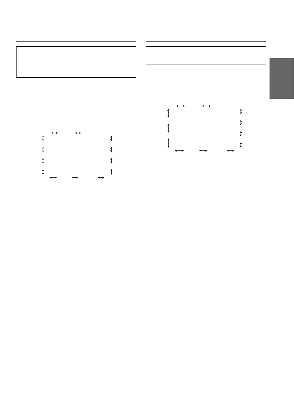
Example 2. Listening Position: All Seats
Adjust the time correction level of each speaker to
almost the same level.
Example 1. Listening Position: Front Left Seat
Adjust the time correction level of the front left
speaker to a high value and the rear right to zero or
a low value.
0.5 m
(19-11/16")
2.25 m
(88-9/16")
5.1 ms
Here we calculate the time correction value for the
front left speaker in the diagram at the left.
Conditions:
Farthest Speaker – listening position: 2.25 m (88-9/16")
Front left speaker – listening position: 0.5 m (19-11/16")
Calculation: L = 2.25 m – 0.5 m = 1.75 m (68-7/8")
*
Time correction = 1.75 ÷ 343
*Speed of sound: 343 m/s (765 mph) at 20˚C
× 1000 = 5.1 (ms)
1 Sit in the listening position (driver’s seat, etc.)
and measure the distance (in meters) between
your head and the various speakers.
2 Calculate the difference between the distance
to the farthest speaker and the other speakers.
L = (distance to farthest speaker) – (distance to
other speakers)
3 Divide the distances calculated for the speakers
by the speed of sound (343 m/s (765 mph) at
20˚C).
These values are the time correction values for
the different speakers.
In other words, giving the front left speaker a time
correction value of 5.1 ms makes it seem as if the
distance to the front left speaker is the same as the
distance to the farthest speaker.
29-EN
Page 32

Adjusting the Sound Operation
BAND
g DN
f UP
MODE/Audio Control
DIVIDER 1 2
Adjusting and Storing the Crossover/
Time Correction
Before performing the following procedures, refer
to “Crossover” (page 28) and “Time Correction”
(page 29).
1 Press and hold the DIVIDER button for at least 2
seconds.
Adjust the cut-off frequency/slope
2 Press the BAND button to select the channel to
adjust.
2 way system
→ Low range (LPF) → Front High range (HPF)
Rear High range (HPF)∗ ←
3 way system
→ Low range (LPF) → Mid range (HPF)
High range (HPF)∗ ← Mid range (LPF) ←
∗ Press the MODE button to activate the Output
Level-adjusting mode.
3 Press the g DN or f UP button to select
the desired cut-off frequency point (cross over
point).
2 way system
You can select the frequency from 20 Hz to 200
Hz (1/3 octave step) for each channel.
3 way system
Low range (LPF) /Mid range (HPF):
You can select the frequency from 20 Hz to 200
Hz (1/3 octave step).
Mid range (LPF) /High range (HPF):
You can select the frequency from 20 Hz to 20
kHz (1/3 octave step).
4 Rotate the Audio Control knob to adjust the
slope.
Slope can be adjusted to FLAT, 6, 12, 18, or 24
db/oct.
5 To adjust another channel, repeat steps 2 to 4.
When the adjustment is completed, press the
DIVIDER button.
Adjust the output level
6 Press the BAND to select the channel to be
adjusted.
2 way system
Low
→→ →
range (L)
Rear high∗
range (R)
3 way system
Low range
→→ →
(L)
High range∗
(R)
∗ Press the MODE button to switch to the Time
Correction Adjusting mode.
Low
range (R)
Rear high
←← ←
range (L)
Low range
(R)
High
←← ←
range (L)
Front high
range (L)
Front high
range (R)
Mid range
(L)
Mid range
(R)
7 Rotate the Audio Control knob to adjust the
output level.
You can adjust the level from –12 to 0.
8 To adjust another channel, repeat the steps 6 to
7, then press the DIVIDER button.
30-EN
Page 33

Adjusting the Time Correction
9 Press the BAND button to select the channel to
be adjusted.
2 way system
Low
→→ →
range (L)
Low
range (R)
Front high
range (L)
Recalling the Stored Crossover/
Time Correction Settings
1 Press the DIVIDER button.
Rear high∗
range (R)
3 way system
Low range
→→ →
(L)
High range∗
(R)
∗ Press the MODE button to switch to the Cut-off
frequency/Slope Adjusting mode.
10
Rotate the Audio Control knob to adjust the
value of the Time Correction (0.0 - 20.0).
11
To adjust another channel, repeat the steps 9 to
10.
12
When all the adjustments are completed, press
and hold the DIVIDER button for at least 2
seconds to cancel the Adjusting mode.
Storing the adjustments
You can store the adjustments.
13
Press and hold the MODE button for at least 2
seconds to store the settings (Or press the 1 or 2
button).
The display flashes.
Rear high
←← ←
range (L)
Low range
(R)
High
←← ←
range (L)
Front high
range (R)
Mid range
(L)
Mid range
(R)
2 Press the g DN or f UP button to select
the stored content (Memory 1 or Memory 2).
Direct Recalling
Press the [1] or [2] button to recall the stored
adjustment.
3 Press the DIVIDER button to return to normal
mode.
NOTE
If you press the MODE button in step 2, the unit switches
to adjusting mode.
14
While the display is flashing, press the 1 or 2
button.
The divider and the Time correction settings are
stored.
15
Press the DIVIDER button to return to normal
mode.
NOTES
• About the 2 w ay/3 w ay system
You can switch to 2way/3 way system mode with the 2
way/3 way switch on the side of the unit. (See on page
47)
3WAY
F/R/Sub-W
• You cannot use the L.P.S. and Time Correction at the
same time.
When setting to “3 WAY”:
The unit can be operated in 3-way
system.
When setting to “F/R/Sub-W”:
The unit can be operated in 2-way
system.
31-EN
Page 34

Adjusting the Sound Operation
MODE/Audio Control
g DN
f UP
CSD
Customized Sound Database
The unit is equipped with a Customized Sound
Database that creates the most suitable sound for
your car type.
You can fine tune the sound effects by inputting
the size of your front speaker or tweeter, whether
there is a Subwoofer, and the material of your
seats.
1 Press and hold the CSD button for at least 2
seconds.
2 Set your car type
Rotate the Audio Control knob to select your
car type, then press the MODE button.
3 Setting the front speaker
Rotate the Audio Control knob to select the
front speaker type, then press the MODE button.
→ 10cm ←→ 13 cm ←→ 16 cm ←
(DDDrive is an Alpine product)
4 Set the separate tweeter
Rotate the Audio Control knob to select
whether the unit has a separate tweeter or not,
then press the MODE button.
W/O TWEETER ←→ W/ TWEETER
(without separate
tweeter)
(with separate
tweeter)
5 Set the subwoofer
Rotate the Audio Control knob to select
whether the unit has a subwoofer or not, then
press the MODE button.
W/O SUB-W ←→ W/ SUB-W
(without Subwoofer)
(with Subwoofer)
6 Set the material of your seats
Rotate the Audio Control knob to select your
seats’ material, then press the MODE button.
CLOTH ←→ LEATHER
7 Complete the settings
After completing the settings, rotate the Audio
Control knob to select CSD OK, then press the
MODE button.
CSD OK? ←→ CSD NO?
CSD OK: The unit automatically customizes the
sound effect according to the above
settings.
CSD NO: Returns to “Set your car type” in step
2.
NOTES
• This function is inoperable when DEFEAT is ON
(refer to page 12).
• While making a setting, press and hold the CSD button
for at least 2 seconds to cancel the setting.
• Press the g DN or f UP button to go forward
or backward to the next/preceding step.
32-EN
Page 35

SOURCE BAND
f UP g DN
XM Radio Operation
Receiving XM Channels with the
XM Receiver (Optional)
XM Satellite Radio* is the next generation of
audio entertainment, with up to 100 brand-new
digital channels. For a small monthly fee,
subscribers can hear crystal-clear music, sports,
news and talk, coast-to-coast via satellite. For
more information, visit XM’s website at
www.xmradio.com or call 1-877-XMRADIO.
An optional XM Satellite Radio Receiver (TUAT020XM) may be connected to the CDA-7878 if it
is Ai-NET compatible. With an XM Receiver
connected to the Ai-NET input of the CDA-7878,
the XM Receiver will be controllable from the
CDA-7878.
* XM and its corresponding logos are trademarks
of XM Satellite Radio Inc.
NOTES
• The controls on the CDA-7878 for XM Receiver
operation are operative only when an XM Receiver is
connected.
• The XM1 or XM2 band illuminates when in XM mode.
1 Press the SOURCE button to select RADIO
Mode.
2 Press the BAND button to select XM1 or XM2.
Each press changes the band:
→ FM1 → FM2 → XM1 → XM2 → AM
3 Press the g DN or f UP button to select
the desired channel. Holding the g DN or
f UP buttons will change channels
continuously.
33-EN
Page 36

XM Radio Operation
TUNE/CAT
g DN
f UP
TITLE
Preset buttons (1 through 6)BAND
SETUP
Checking the XM Radio ID Number
You need to provide XM with the unique XM
Radio ID number for your XM Radio Receiver in
order to subscribe to XM's programming.
This number is an 8 character alphanumeric
number that is printed on a label directly on the
XM Receiver.
It can also be displayed on the screen of the CDA7878 in the following way.
1 While receiving XM1/XM2, press the g DN or
f UP button to select channel “0.”
2 The unit alternately displays “RADIO ID” for 2
seconds, then the ID number for 10 seconds.
3 To cancel the ID number display, set the channel
to other than “0.”
NOTE
There is another way to display your ID number.
1. Press and hold the SETUP button for at least 2
seconds.
2. Press the f UP button repeatedly to select “ID.”
Each press of the f UP button changes the modes
as shown:
ID TUNER SUB-W
DEMO
CONTRAST
AUX
MUTE SCROLL BEEP
* Displayed when you set SUB-W to ON.
If you press the g DN button, the display scrolls in
reverse sequence.
SUB-W (switching phase)
SUB-W STEREO/MONO
SRC DHE
DISC/FOLDER
∗
∗
3. Press the TUNE button to display your ID number.
4. After checking your ID number, press the SETUP
button to return to the normal display.
Storing XM Channel Presets
1 Press the BAND button to select the desired
band (XM1 or XM2) you want to store.
2 After tuning in the desired channel, press and
hold any one of the Preset buttons (1 through
6) for at least 2 seconds until the channel number
on the display blinks.
3 Press the Preset button into which you wish to
store the channel while the channel number
display is blinking (within 5 seconds).
The display stops blinking once the channel has
been memorized. The display shows the band,
preset No. with a triangle (9) and channel
number memorized.
4 Repeat the procedure to store up to 5 other
channels onto the same band.
To use this procedure for other bands, simply
select the band desired and repeat the
procedure.
A total of 12 channels can be stored in the preset
memory (6 channels for each band; XM1 and
XM2).
NOTE
If you store a channel in a preset memory which already
has a station, the current channel will be cleared and
replaced with the new one.
34-EN
Page 37

Receiving Stored XM Channels
Changing the Display
1 Press the BAND button to select the desired
band (XM1 or XM2).
→ FM1 → FM2 → XM1 → XM2 → AM
2 Press the channel Preset button that has your
desired satellite channel in memory.
Category Search
Category Search functionality allows you to
search for a specific channel by the category of
programming it offers, or to surf within a given
category.
1 In XM mode, press the CAT button to display the
category of the channel that is currently selected
for 5 seconds.
2 While the category is displayed, press the
g DN or f UP button to select a different
category (or leave it to stay with the same
category.)
3 Within 5 seconds of selecting the category, press
the CAT button again to select the next channel
within that category. Repeatedly press the CAT
button within 5 seconds to select additional
channels within that category.
When tuned in, the category is displayed for 5
seconds, then the display returns to normal
mode.
NOTE
If you cannot find your desired category, the display
shows “
------
” for 5 seconds automatically.
Text information, such as the channel name, artist
name/feature, and song/program title, is available
with each XM channel. The unit can display this
text information as explained below.
1 In XM mode, press the TITLE button.
Each time you press this button, the display
changes as shown below.
Channel Number
display
Song Title
display
NOTES
• When The “Scroll Setting” (refer to page 10) is set to
“SCROLL AUTO”, the display scrolls.
When the CD Text Scroll Setting is set to “SCROLL
MANU”, the display scrolls only when you operate the
unit (POWER ON, BAND, etc., are displayed.)
Press the TITLE button for more than 3 seconds to
scroll the display again.
• “Channel Number” and “Clock” displays do not
scroll.
→→→
CLOCK
display
←
Channel Name
display
Artist Name
display
←
35-EN
Page 38

Remote Control Operation
1
2
3
4
5
6
7
8
9
!
"
#
Controls on Remote Control
1 Power Button
Press the button to turn the power on/off.
2 Source Button
Press to select the audio source.
3 -/J Button
Press the button to switch between the Play and
Pause modes for CD.
4 ANGLE 89 Buttons
Press the button to adjust the angle of the
movable display.
5 Band/Program Button
Radio mode: BAND Button
Press the button and the band will change as
shown below.
→ FM1 → FM2 → XM1 → XM2 → AM
CD/Changer mode: To switch the disc mode.
6 Volume Adjustment Buttons
To increase the volume level:
Press the L button
To decrease the volume level:
Press the K button
7 8 Button
Radio mode: Pressing the button will select, in
ascending order, stations programmed into the
radio's presets as shown below.
8 g DN Button
Radio mode: SEEK (DN) Button
CD mode: Press the button to go back to the
beginning of the current track.
9 f UP Button
Radio mode: SEEK (UP) Button
CD mode: Press the button to advance to the
beginning of the next track.
! 9 Button
Radio mode: Pressing the button will select, in
descending order, stations programmed into the
radio's presets as shown below.
→ 6 → 5 ... 1
CD (MP3) mode: Press the Folder Select (DN)
Button to select the folder.
CD Changer mode: DISC Select (DN) Button
Press the button to select a disc in descending
order.
" Mute Button
Press the button to lower the volume by 20 dB
instantly. Press the button again to cancel.
# Audio Processor Button
Each press the button to switch the audio
processor mode.
For details, refer to page 38.
→ 1 → 2 ... 6
CD (MP3) mode: Press the Folder Select (UP)
Button to select the folder.
CD Changer mode: DISC Select (UP) Button
Press the button to select a disc in ascending order.
36-EN
Page 39

Battery Replacement
Applicable battery: Use two “AAA” sized dry
batteries or equivalent.
1 Opening the battery cover
Slide out the battery cover while firmly pressing
the direction of arrow.
2 Replacing the battery
Put the batteries in the case observing the
polarities as illustrated.
3 Closing the cover
Push the cover as illustrated until a click is
heard.
37-EN
Page 40

Remote Control Operation
Operating the Audio Processor
Steps
1 Press the
A.PROC
button to
select the
mode.
2 Press the 8
or 9 button
to select the
mode.
→
Normal
mode
Selecting DHE
mode
DHE mode
→
↓
NON
EFFECT
↑
↓
BASS
MODE1
↑
↓
BASS
MODE2
↑
↓
BASS
MODE3
↑
↓
VOCAL
MODE
↑
↓
ALL MODE
→
Equalizer
Presets
EQ mode
↓
FLAT
↑
↓
POPS
↑
↓
ROCK
↑
↓
NEWS
↑
Recalling the
Stored
Equalizer
Curve
Private
→
mode
MEMORY1
MEMORY2
MEMORY3
MEMORY4
MEMORY5
MEMORY6
Choosing the
Listening
Position
Select
LPS mode
→
↓
↑
↓
↑
↓
↑
↓
↑
↓
↑
↓
↓
OFF
↑
↓
ALL
↑
↓
FRONT
↑
↓
FRONT-L
↑
↓
FRONT-R
↑
Recalling the
Stored
Crossover/Time
Collection
Crossover
→
mode
↓
MEMORY1
↑
↓
MEMORY2
↑
↑
Adjusting/Storing the EQ curve
Adjusting
1 Perform the procedure above to select the
desired equalizer characteristics.
2 Press the ENTER button to activate the
Adjusting Mode.
3 Press the g DN or f UP button to select
the frequency to be adjusted.
4 Press the 8 or 9 button to adjust to your desired
level.
To adjust other frequencies, repeat steps 3 to 4.
↑
Storing
5 Press and hold the ENTER button for at least 2
seconds to flash the display.
6 Press the 8 or 9 button to select the preset
number (1 through 6) that you want to store.
7 Press the ENTER button to store the setting. To
store settings, repeat the procedure above.
8 Press the A.PROC button to return to normal
mode.
38-EN
Page 41

Adjusting/Storing the CROSSOVER/TIME CORRECTION
Adjusting
1 Select the Crossover mode from the table above.
Storing the settings
12
Press and hold the ENTER button for more than
2 seconds to flash the display.
2 Press the ENTER button to activate the
Adjusting mode.
13
Press the 8 or 9 button to select the preset
number (1 to 2) that you want to store.
3 Press the BAND button to select the channel
(LPF/HPF) that you want to adjust.
4 Press the g DN or f UP button to select
the cut-off frequency.
5 Press the 8 or 9 button to select the Slope.
To adjust more channels, repeat steps 3 to 5.
14
Press the ENTER button to store the adjustment.
Store other adjustments, repeat the procedures
above.
15
Press the A.PROC button to return to normal
mode.
6 Press the ENTER button to activate the
Adjusting level mode.
7 Press the BAND button to select the channel you
want to adjust.
8 Press the 8 or 9 button to adjust the level.
To adjust more channels, repeat steps 7 to 8.
9 Press the ENTER button to activate the Time
Correction Adjusting mode.
10
Press the BAND button to select the channel
that you want to adjust.
11
Press the 8 or 9 button to adjust the Time
Correction. To adjust more channels, repeat
steps 10 to 11.
39-EN
Page 42

Information
In Case of Difficulty
If you encounter a problem, please review the items in
the following checklist. This guide will help you
isolate the problem if the unit is at fault. Otherwise,
make sure the rest of your system is properly
connected or consult your authorized Alpine dealer.
Basic
No function or display.
• Vehicle's ignition is off.
- If connected following instructions, the unit will not
operate with the vehicle's ignition off.
• Improper power lead connections.
- Check power lead connections.
• Blown fuse.
- Check the fuse on the battery lead of the unit; replace
with the proper value if necessary.
• Internal micro-computer malfunctioned due to
interference noise etc.
- Press the RESET switch with a ballpoint pen or other
pointed article.
Radio
Unable to receive stations.
• No antenna or open connection in cable.
- Make sure the antenna is properly connected;
replace the antenna or cable if necessary.
Unable to tune stations in the seek mode.
• You are in a weak signal area.
- Make sure the tuner is in the DX mode.
• If the area you are in is a primary signal area, the
antenna may not be grounded and connected properly.
- Check your antenna connections; make sure the
antenna is properly grounded at its mounting location.
• The antenna may not be the proper length.
- Make sure the antenna is fully extended; if broken,
replace the antenna with a new one.
Broadcast is noisy.
• The antenna is not the proper length.
- Extend the antenna fully; replace it if it is broken.
• The antenna is poorly grounded.
- Make sure the antenna is grounded properly at its
mounting location.
CD
CD Player/Changer not functioning.
• Out of operating temperature range +50˚C (+120˚F) for
CD.
- Allow the vehicle's interior (or trunk) temperature to
cool.
CD playback sound is wavering.
• Moisture condensation in the CD Module.
- Allow enough time for the condensation to evaporate
(about 1 hour).
CD insertion not possible.
• A CD is already in the CD player.
- Eject the CD and remove it.
• The CD is being improperly inserted.
- Make sure the CD is being inserted following
instructions in the CD Player Operation section.
Unable to fast forward or backward the CD.
• The CD has been damaged.
- Eject the CD and discard it; using a damaged CD in
your unit can cause damage to the mechanism.
CD playback sound skips due to vibration.
• Improper mounting of the unit.
- Securely re-mount the unit.
• Disc is very dirty.
- Clean the disc.
• Disc has scratches.
- Change the disc.
• The pick-up lens is dirty.
- Do not use a commercial available lens cleaner disc.
Consult your nearest ALPINE dealer.
CD playback sound skips without vibration.
• Dirty or scratched disc.
- Clean the disc; damaged disc should be replaced.
Error displays (built-in CD player only)
• Mechanical error
- Press the c button. After the error indication
disappears, insert the disc again. If the abovementioned solution does not solve the problem,
consult your nearest ALPINE dealer.
MP3
MP3 is not played back.
• Writing error is occurred. The written format is not
right.
- Make sure the writing is not failed. Or refer to "About
MP3" on page 24, then write in the format supported
by this device.
40-EN
Page 43

Indication for CD Player
Indication for CD Changer
HI TEMP
• Protective circuit is activated due to high temperature.
- The indicator will disappear when the temperature
returns to within operation range.
NO DISC
• No CD is inserted.
- Insert a CD.
• Although a disc is inserted, “NO DISC” is displayed
and the unit does not start to play or eject the disc.
- Remove the disc by following these steps:
1) Press the c button.
The movable display will open.
2) Press the c button again for at least 3 seconds while
the movable display is open.
ERROR
• Mechanism error.
1)Press the c button and eject the CD.
If not ejecting, consult your Alpine dealer.
2)When the error indication remains after ejecting,
press the c button again.
If the error indication still does not turn off after
pressing the c button for a few times, consult your
Alpine dealer.
NOTE
When the “ERROR” is displayed:
In case that the disc cannot be ejected by pressing the c
button, press the RESET switch (refer to page 4) and
press the c button again.
If not ejecting, consult your Alpine dealer.
HI TEMP
• Protective circuit is activated due to high temperature.
- The indicator will disappear when the temperature
returns to within operation range.
ERROR - 01
• Malfunction in the CD Changer.
- Consult your Alpine dealer. Press the magazine eject
button and pull out the magazine.
Check the indication. Insert the magazine again.
If the magazine cannot be pulled out, consult your
Alpine dealer.
• Magazine ejection not possible.
- Press the magazine eject button. If the magazine does
not eject, consult your Alpine dealer.
ERROR - 02
• A disc is left inside the CD Changer.
- Press the Eject button to activate the eject function.
When the CD Changer finishes the eject function,
insert an empty CD magazine into the CD Changer to
receive the disc left inside the CD Changer.
NO MAGAZINE
• No magazine is loaded into the CD Changer.
- Insert a magazine.
NO DISC
• No indicated disc.
- Choose another disc.
41-EN
Page 44

Information
Indication for XM Radio Mode
ANTENNA
• The XM antenna is not connected to the XM radio
module.
- Check whether the XM antenna cable is attached
securely to the XM radio module.
UPDATING
• Radio is being updated with latest encryption code.
- Wait until encryption code is being updated. Channels
0 and 1 should function normally.
NO SIGNAL
• XM signal is too weak at the current location.
- Wait until the car reaches a location with a stronger
signal.
LOADING
• Radio is acquiring audio or program information.
- Wait until the radio has received the information.
OFF AIR
• The channel currently selected has stopped
broadcasting.
- Select another channel.
– – – – – –
• The user has selected a Channel Number that does not
exist or is not subscribed to.
- The unit will revert back to the previously selected
channel.
• There is no artist name/feature, song/program title, or
additional information associated with the channel at
that time.
- No action needed.
42-EN
Page 45

Specifications
CAUTION
FM TUNER SECTION
Tuning Range 87.7 – 107.9 MHz
Mono Usable Sensitivity 9.3 dBf (0.8 µV/75 ohms)
50 dB Quieting Sensitivity 13.5 dBf (1.3 µV/75 ohms)
Alternate Channel Selectivity 80 dB
Signal-to-Noise Ratio 80 dB
Stereo Separation 45 dB
Capture Ratio 2.0 dB
AM TUNER SECTION
Tuning Range 530 – 1,710 kHz
Sensitivity (IEC Standard) 22.5 µV/27 dB
CD PLAYER SECTION
Frequency Response 5 – 20,000 Hz (±1 dB)
Wow & Flutter (% WRMS) Below measurable limits
Total Harmonic Distortion 0.008% (at 1 kHz)
Dynamic Range 95 dB (at 1 kHz)
Signal-to-Noise Ratio 95 dB
Channel Separation 85 dB (at 1 kHz)
PICKUP
Wave length 655nm
Laser power CLASS II
REMOTE CONTROL
Battery Type AAA batteries (2 pcs.)
Width 42 mm (1-21/32")
Height 121 mm (4-25/32")
Depth 23 mm (29/32")
Weight 50 g (1.8 oz)
CAUTION-Laser radiation when open, DO NOT STARE INTO BEAM
(Bottom side of player)
GENERAL
Power Requirement 14.4 V DC
(11–16 V allowable)
Maximum Power Output 45 W × 4
Maximum Pre-Output Voltage 4 V/10 k ohms
Weight 1.8 kg (3 lbs. 15 oz)
CHASSIS SIZE
Width 178 mm (7")
Height 50 mm (2")
Depth 155 mm (6-1/8")
NOSEPIECE SIZE
Width 170 mm (6-11/16")
Height 46 mm (1-13/16")
Depth 24 mm (15/16")
Due to continuous product improvement, specifications and
design are subject to change without notice.
43-EN
Page 46

Installation and Connections
Before installing or connecting the unit, please
read the following and pages 2 and 3 of this
manual thoroughly for proper use.
Warning
MAKE THE CORRECT CONNECTIONS.
Failure to make the proper connections may result in fire
or product damage.
USE ONLY IN CARS WITH A 12 VOLT NEGATIVE
GROUND.
(Check with your dealer if you are not sure.) Failure to do
so may result in fire, etc.
BEFORE WIRING, DISCONNECT THE CABLE FROM
THE NEGATIVE BATTERY TERMINAL.
Failure to do so may result in electric shock or injury due
to electrical shorts.
DO NOT ALLOW CABLES TO BECOME ENTANGLED
IN SURROUNDING OBJECTS.
Arrange wiring and cables in compliance with the manual
to prevent obstructions when driving. Cables or wiring
that obstruct or hang up on places such as the steering
wheel, gear lever, brake pedals, etc. can be extremely
hazardous.
DO NOT SPLICE INTO ELECTRICAL CABLES.
Never cut away cable insulation to supply power to other
equipment. Doing so will exceed the current carrying
capacity of the wire and result in fire or electric shock.
DO NOT DAMAGE PIPE OR WIRING WHEN
DRILLING HOLES.
When drilling holes in the chassis for installation, take
precautions so as not to contact, damage or obstruct pipes,
fuel lines, tanks or electrical wiring. Failure to take such
precautions may result in fire.
DO NOT USE BOLTS OR NUTS IN THE BRAKE OR
STEERING SYSTEMS TO MAKE GROUND
CONNECTIONS.
Bolts or nuts used for the brake or steering systems (or
any other safety-related system), or tanks should NEVER
be used for installations or ground connections. Using
such parts could disable control of the vehicle and cause
fire etc.
KEEP SMALL OBJECTS SUCH AS BATTERIES OUT
OF THE REACH OF CHILDREN.
Swallowing them may result in serious injury.
If swallowed, consult a physician immediately.
DO NOT INSTALL IN LOCATIONS WHICH MIGHT
HINDER VEHICLE OPERATION, SUCH AS THE
STEERING WHEEL OR GEARSHIFT.
Doing so may obstruct forward vision or hamper
movement etc. and results in serious accident.
Caution
HAVE THE WIRING AND INSTALLATION DONE BY
EXPERTS.
The wiring and installation of this unit requires special
technical skill and experience. To ensure safety, always
contact the dealer where you purchased this product to
have the work done.
USE SPECIFIED ACCESSORY PARTS AND INSTALL
THEM SECURELY.
Be sure to use only the specified accessory parts. Use of
other than designated parts may damage this unit internally
or may not securely install the unit in place. This may cause
parts to become loose resulting in hazards or product failure.
ARRANGE THE WIRING SO IT IS NOT CRIMPED OR
PINCHED BY A SHARP METAL EDGE.
Route the cables and wiring away from moving parts (like
the seat rails) or sharp or pointed edges. This will prevent
crimping and damage to the wiring. If wiring passes through
a hole in metal, use a rubber grommet to prevent the wire’s
insulation from being cut by the metal edge of the hole.
DO NOT INSTALL IN LOCATIONS WITH HIGH
MOISTURE OR DUST.
Avoid installing the unit in locations with high incidence
of moisture or dust. Moisture or dust that penetrates into
this unit may result in product failure.
Precautions
• Be sure to disconnect the cable from the (–) battery post before
installing your CDA-7878. This will reduce any chance of
damage to the unit in case of a short-circuit.
• Be sure to connect the color coded leads according to the
diagram. Incorrect connections may cause the unit to
malfunction or damage to the vehicle's electrical system.
• When making connections to the vehicle's electrical system, be
aware of the factory installed components (e.g. on-board
computer). Do not tap into these leads to provide power for this
unit. When connecting the CDA-7878 to the fuse box, make sure
the fuse for the intended circuit of the CDA-7878 has the
appropriate amperage. Failure to do so may result in damage to
the unit and/or the vehicle. When in doubt, consult your ALPINE
dealer.
• The CDA-7878 uses female RCA-type jacks for connection to
other units (e.g. amplifier) having RCA connectors. You may
need an adaptor to connect other units. If so, please contact
your authorized ALPINE dealer for assistance.
• Be sure to connect the speaker (–) leads to the speaker (–)
terminal. Never connect left and right channel speaker cables
to each other or to the vehicle body.
IMPORTANT
Please record the serial number of your unit in the
space provided below and keep it as a permanent
record. The serial number plate is located on the
bottom of the unit.
44-EN
SERIAL NUMBER:
INSTALLATION DATE:
INSTALLATION TECHNICIAN:
PLACE OF PURCHASE:
Page 47

Installation
Metal plate
Detachable
Front panel
Caution
When you install this unit in your car, do not remove
the Detachable Front Panel.
If the Detachable Front Panel is removed during
installation, you might press too hard and warp the
metal plate that holds it in place.
Caution
Do not block the unit’s fan or heat sink, thus
preventing air circulation. If blocked, heat will
accumulate inside the unit and may cause a fire.
Air ventilation
hole
<Rear side>
1
Slide mounting sleeve from main unit (See "Removal"
on this page.)
Slide mounting sleeve into the dashboard.
2
Mounting Sleeve
(Included)
Hex Nut (M5)
Dashboard
CDA-7878
Screw
Connect each input lead coming from an amplifier or
equalizer to the corresponding output lead coming
from the left rear of the CDA-7878. Connect all other
leads of the CDA-7878 according to details
described in the CONNECTlONS section.
3
Lock Pin
Slide the CDA-7878 into the dashboard. When the
unit is in place, make sure the locking pins are fully
seated in the down position. This can be done by
pressing firmly in on the unit while pushing the
locking pin down with a small screwdriver. This
ensures that the unit is properly locked and will not
accidentally come out from the dashboard. Install the
Detachable Front Panel.
Removal
1 Remove the DETACHABLE FRONT PANEL.
2 Use a small screwdriver (or similar tool) to push
the locking pins to the “up” position (see above
drawing). As each pin is unlocked, gently pull out
on the unit to make sure it does not re-lock before
unlocking the second pin.
3 Pull the unit out, keeping it unlocked as you do
so.
<JAPANESE CAR>
Face Plate
∗∗
Bolt Stud
Metal
Mounting
Strap
Ground Lead
Reinforce the head unit with the metal mounting
strap (not supplied). Secure the ground lead of the
unit to a clean metal spot using a screw (
attached to the vehicle's chassis.
NOTE
For the screw marked **, use an appropriate screw for
the chosen mounting location.
∗
Chassis
CDA-7878
) already
∗
Screws (M5 × 8)
CDA-7878
Ground Lead
(Included)
∗
Mounting Bracket
NOTE
Secure the ground lead of the unit to a clean metal spot
using a screw (
chassis.
) already attached to the vehicle's
∗
45-EN
Page 48

Installation and Connections
Connections
Antenna
Choke coil
1
;
Ai-NET
NORM EQ/DIV
(Bottom of the unit)
3WAY
<
~
8
9
Blue
Blue/White
Pink/Black
Red
Ye l l o w
Black
SPEAKER RIGHT FRONT
Gray/Black
Violet/Black
SPEAKER RIGHT REAR
SPEAKER LEFT REAR
Green/Black
White/Black
SPEAKER LEFT FRONT
POWER ANT
REMOTE
TURN-ON
AUDIO
INTERRUPT IN
IGNITION
BATTERY
GND
Gray
Violet
Green
White
2
3
4
5
6
7
!
"
#
$
%
&
(
)
To power antenna
To amplifier or equalizer
To vehicle phone
Ignition Key
Front right
Rear right
Speakers
Rear left
Front left
Battery
CD Changer
(Sold Separately)
+
F/R/Sub-W
(Side of the unit)
,
-
:
Amplifier
Speakers
Front Left
Front Right
.
:
Amplifier
Rear Left
Rear Right
/
:
Amplifier
Subwoofers
For details on how to set the Subwoofer to ON/OFF, see “Subwoofer On and Off” on page 7.
To prevent external noise from entering the audio system.
• Locate the unit and route the leads at least 10 cm away from the car harness.
• Keep the battery power leads as far away from other leads as possible.
• Connect the ground lead securely to a bare metal spot (remove any paint, dirt or grease if necessary) of the car chassis.
• If you add an optional noise suppressor, connect it as far away from the unit as possible. Your Alpine dealer carries
various noise suppressors, contact them for further information.
• Your Alpine dealer knows best about noise prevention measures so consult your dealer for further information.
46-EN
Page 49

1 Antenna Receptacle
2 Power Antenna Lead (Blue)
Connect this lead to the +B terminal of your power
antenna, if applicable.
NOTE
This lead should be used only for controlling the
vehicle's power antenna. Do not use this lead to turn on
an amplifier or a signal processor, etc.
3 Remote Turn-On Lead (Blue/White)
Connect this lead to the remote turn-on lead of your
amplifier or signal processor.
4 Audio Interrupt In Lead (Pink/Black)
5 Switched Power Lead (Ignition) (Red)
Connect this lead to an open terminal on the vehicle's
fuse box or another unused power source which
provides (+)12V only when the ignition is turned on
or in the accessory position.
6 Battery Lead (Yellow)
Connect this lead to the positive (+) post of the
vehicle's battery.
7 Ground Lead (Black)
Connect this lead to a good chassis ground on the
vehicle. Make sure the connection is made to bare
metal and is securely fastened using the sheet metal
screw provided.
8 Fuse Holder (15A)
9 Power Supply Connector
! Right Front (+) Speaker Output Lead (Gray)
" Right Front (–) Speaker Output Lead (Gray/
Black)
# Right Rear (–) Speaker Output Lead (Violet/
Black)
$ Right Rear (+) Speaker Output Lead (Violet)
% Left Rear (+) Speaker Output Lead (Green)
& Left Rear (–) Speaker Output Lead (Green/
Black)
( Left Front (–) Speaker Output Lead (White/Black)
) Left Front (+) Speaker Output Lead (White)
~ Ai-NET Connector
Connect this to the output or input connector of other
product (CD Changer, Equalizer, etc.) equipped with
Ai-NET.
NOTE
You can input TV/video sound by connecting an optional
Ai-NET/RCA Interface cable (KCA-121B) to this
component.
+ DC/DC Converter
NOTES
• Do not install the converter at a location subjected to
water such as under the floor mat or air conditioner.
This may cause a malfunction.
• Do not bundle the DC/DC converter cable with other
audio cables. Doing so may induce noise into your
system.
• Keep the DC/DC converter away from the Antenna
cables and the rear side of the unit, otherwise noise
may be generated when receiving radio broadcast.
, Ai-NET Cable (Included with CD Changer)
- Front Output RCA Connectors
RED is right and WHITE is left.
. Rear Output RCA Connectors
RED is right and WHITE is left.
/ Subwoofer RCA Connectors
RED is right and WHITE is left.
: RCA Extension Cable (Sold Separately)
; System Switch
When connecting a processor or divider using Ai-NET,
place this switch in the EQ/DIV position. When no device
is connected, leave the switch in the NORM position.
NOTE
Be sure to turn the power off to the unit before changing
the switch position.
< Setting the 3WAY/2 WAY switch
Set the 3way/2way Switch according to your audio system.
The system whose frequency range is divided
between the high frequency range and the low
frequency range.
The position of switching the switch: F/R/Sub-W
Front high range
speaker (L)
Rear high range
speaker (L)
Low range
speaker (L)
Output of this unit :
NOTES
• Use the SUB-W output cord to connect the unit to the Low Range speaker.
• You can use the built-in amplifier to output the Front output/Rear output.
• You cannot adjust the FADER when setting to 3 WAY.
Front high range
speaker (R)
Rear high range
speaker (R)
Low range
speaker (R)
Front output Rear output SUB-W output
The system whose frequency range is divided
among the high frequency range, mid frequency
range, and the low frequency range.
The position of switching the switch: 3WAY
High range
speaker (L)
Mid range
speaker (L)
Low range
speaker (L)
High range
speaker (R)
Mid range
speaker (R)
Low range
speaker (R)
47-EN
Page 50

48-EN
 Loading...