

Page 1
MOTO RHOME SERIES
3000/4000
OPERATOR’S
MANUAL
Page 2

Operator’s
Manual
2005 FEBRUARY
Rev. 1 2005 SEPTEMBER
OM3349EN
Allison Transmission
VOCATIONAL MODELS
Motorhome Series (MH) Transmissions
3000 and 4000 Product Families
WTEC III Controls and Allison 4
3000 MH
4000 MH
th
Generation Controls
Printed in USA
Copyright © 2005 General Motors Corporation
Page 3

NOTES
2
Page 4

TABLE OF CONTENTS
INTRODUCTION
KEEPINGTHATALLISONADVANTAGE ........................ 7
A BRIEF DESCRIPTION OF THE ALLISON MOTORHOME SERIES
TRANSMISSIONS ...................................... 12
ELECTRONIC CONTROL SYSTEM ........................... 12
TORQUE CONVERTER ................................... 13
PLANETARYGEARSANDCLUTCHES ........................ 14
COOLER CIRCUIT ...................................... 14
RETARDER...........................................15
SHIFT SELECTORS
DESCRIPTION OF AVAILABLE TYPES .........................16
INTRODUCTION ....................................... 17
LEVER SHIFT SELECTOR ................................. 18
PUSHBUTTON SHIFT SELECTOR ............................20
RANGE SELECTION ..................................... 21
DRIVING TIPS
CHECKTRANSLIGHT ................................... 26
DIAGNOSTIC CODES .................................... 27
ACCELERATOR CONTROL ................................ 27
DOWNSHIFT AND DIRECTION CHANGE INHIBITOR FEATURE ....... 27
USINGTHEENGINETOSLOWTHEVEHICLE ................... 29
USING THE HYDRAULIC RETARDER ......................... 29
ADAPTING SHIFTS ..................................... 32
RANGE PRESELECTION .................................. 34
COLDWEATHERSTARTS ................................. 34
DRIVING ON SNOW OR ICE ............................... 35
ROCKINGOUT ........................................ 36
HIGHFLUIDTEMPERATURE .............................. 36
PARKINGBRAKE ...................................... 37
TOWING OR PUSHING ...................................38
PRIMARY/SECONDARY SHIFT SCHEDULES .................... 38
CRUISECONTROLOPERATION ............................. 38
TURNINGOFFTHEVEHICLE .............................. 39
POWER TAKEOFF OPERATION
ENGINE-DRIVENPOWERTAKEOFF(PTO) ..................... 40
3
Page 5

CARE AND MAINTENANCE
PERIODIC INSPECTIONS ................................. 41
PREVENT MAJOR PROBLEMS ..............................41
IMPORTANCE OF PROPER FLUID LEVEL ...................... 42
FLUID LEVEL CHECK USING PUSHBUTTON OR LEVER SHIFT
SELECTOR ...........................................43
MANUAL FLUID CHECK PROCEDURE ....................... 47
COLDCHECK ......................................... 49
HOTCHECK .......................................... 50
RECOMMENDED AUTOMATIC TRANSMISSION FLUID AND VISCOSITY
GRADE ............................................. 50
KEEPINGFLUIDCLEAN ..................................51
FLUID AND INTERNAL FILTER CHANGE INTERVAL
RECOMMENDATIONS ................................... 52
TRANSMISSION FLUID CONTAMINATION ..................... 56
TRANSMISSION FLUID AND FILTER CHANGE PROCEDURE ......... 57
DIAGNOSTICS
INTRODUCTION ....................................... 60
DIAGNOSTIC CODES .................................... 60
DIAGNOSTIC CODE DISPLAY PROCEDURE .....................63
DIAGNOSTIC CODE LISTINGS AND PROCEDURES
(WTECIIICONTROLS) ................................... 65
DIAGNOSTIC CODE LISTINGS AND PROCEDURES (ALLISON 4
GENERATIONCONTROLS) ................................ 73
th
ABBREVIATIONS AND DEFINITIONS
ABBREVIATIONS AND DEFINITIONS ......................... 84
CUSTOMER SERVICE
OWNER ASSISTANCE ................................... 86
SERVICELITERATURE ...................................88
ALLISON TRANSMISSION DISTRIBUTORS ..................... 90
ALLISON TRANSMISSION REGIONAL OFFICES .................. 92
4
Page 6

TRADEMARK USAGE
The following trademarks are the property of the companies indicated:
• Allison DOC™ is a trademark of General Motors Corporation.
• DEXRON
• TranSynd™ is a trademark of Castrol Ltd.
®
is a registered trademark of the General Motors Corporation.
5
Page 7
WARNINGS, CAUTIONS, NOTES
IT IS YOUR RESPONSIBILITY to be completely familiar with the warnings
and cautions described in this manual. It is, however, important to understand that
these warnings and cautions are not exhaustive. Allison Transmission could not
possibly know, evaluate, and advise the service trade of all conceivable ways in
which service might be done or of the possible hazardous consequences of each
way. The vehicle manufacturer is responsible for providing information related to
the operation of vehicle systems (including appropriate warnings, cautions, and
notes). Consequently, Allison Transmission has not undertaken any such broad
evaluation. Accordingly, ANYONE WHO USES A SERVICE PROCEDURE
OR TOOL WHICH IS NOT RECOMMENDED BY ALLISON
TRANSMISSION OR THE VEHICLE MANUFACTURER MUST first be
thoroughly satisfied that neither personal safety nor equipment safety will be
jeopardized by the service methods selected.
Proper service and repair is important to the safe, reliable operation of the
equipment. The service procedures recommended by Allison Transmission (or the
vehicle manufacturer) and described in this manual are effective methods for
performing service operations. Some of these service operations require the use of
tools specially designed for the purpose. The special tools should be used when
and as recommended.
Three types of headings are used in this manual to attract your attention. These
warnings and cautions advise of specific methods or actions that can result in
personal injury, damage to the equipment, or cause the equipment to become
unsafe.
WARNING: A warning is used when an operating procedure, practice,
etc., if not correctly followed, could result in personal injury or loss of
life.
CAUTION: A caution is used when an operating procedure, practice,
etc., if not strictly observed, could result in damage to or destruction of
equipment.
NOTE: A note is used when an operating procedure, practice, etc., is
essential to highlight.
6
Page 8
INTRODUCTION
KEEPING THAT ALLISON ADVANTAGE
Allison Motorhome Series (MH) transmissions provide many advantages for the
driver who must “stop and go” or change speeds frequently. Driving is easier,
safer, and more efficient.
The Motorhome Series transmissions are rugged and designed to provide long,
trouble-free service. This manual will help you gain maximum benefits from your
ALLISON-equipped vehicle.
7
Page 9
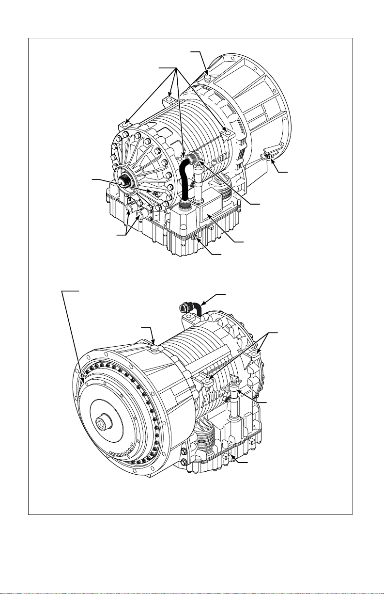
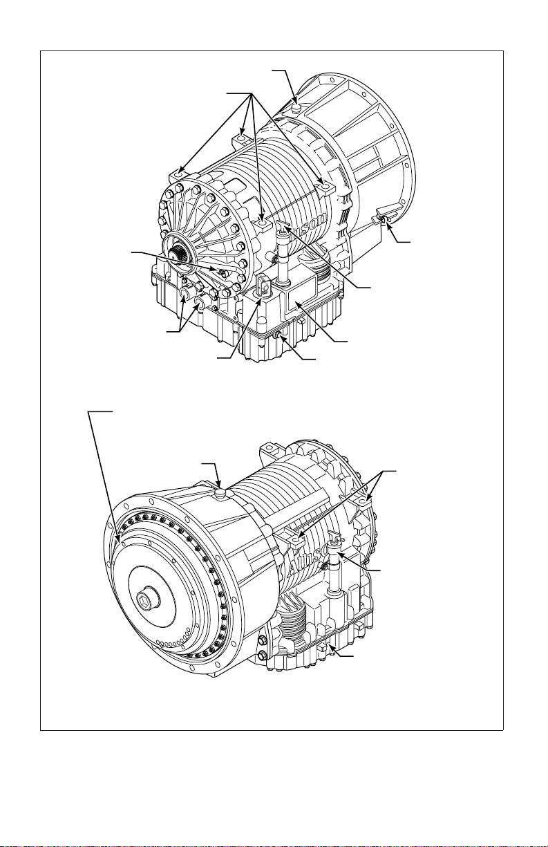
BREATHER
ASSEMBLY PADS
OUTPUT
SPEED
SENSOR
COOLER PORTS
NOTE: Inch Series Threads
TORQUE CONVERTER
WITH LOCKUP CLUTCH
AND TORSIONAL DAMPER
BREATHER
INPUT
SPEED
SENSOR
FEEDTHROUGH
HARNESS
CONNECTOR
NAMEPLATE
MAIN-PRESSURE TAP
NOTE: Inch Series Threads
FEEDTHROUGH
HARNESS
CONNECTOR
ASSEMBLY
PADS
(BOTH SIDES)
FILL TUBE
AND DIPSTICK
(Available on
both sides)
MAIN-PRESSURE TAP
NOTE: Inch Series Threads
Figure 1. Typical 3000 MH Series Transmission
(WTEC III Controls)
8
V06341.02.00
Page 10
BREATHER
ASSEMBLY PADS
OUTPUT
SPEED
SENSOR
COOLER PORTS
NOTE: Inch Series Threads
FEEDTHROUGH
HARNESS CONNECTOR
TORQUE CONVERTER
WITH LOCKUP CLUTCH
AND TORSIONAL DAMPER
BREATHER
INPUT
SPEED
SENSOR
FILL TUBE
AND DIPSTICK
(Available on
both sides)
NAMEPLATE
MAIN-PRESSURE TAP
NOTE: Inch Series Threads
ASSEMBLY
PADS
(BOTH SIDES)
FILL TUBE
AND DIPSTICK
(Available on
both sides)
MAIN-PRESSURE TAP
NOTE: Inch Series Threads
Figure 2. Typical 3000 MH Series Transmission
(Allison 4
th
Generation Controls)
9
V06341.03.01
Page 11
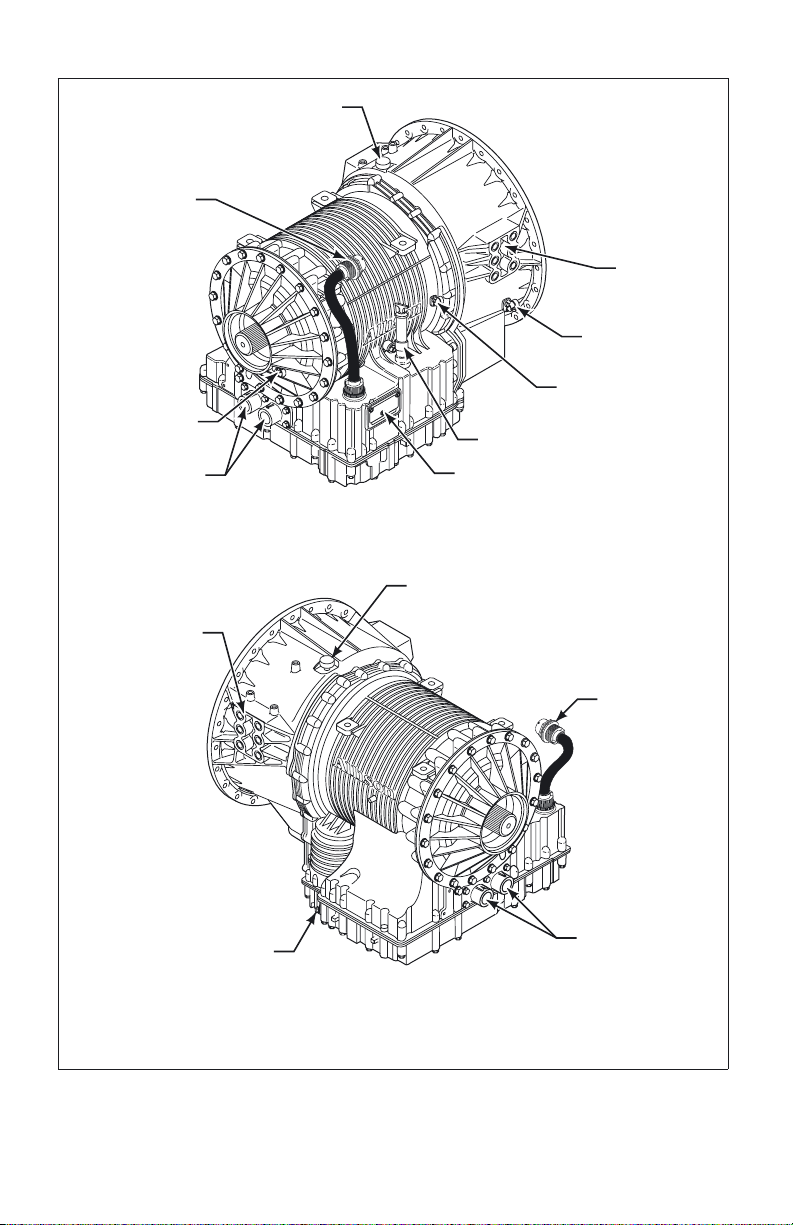
FEEDTHROUGH
HARNESS
CONNECTOR
OUTPUT SPEED
SENSOR
COOLER PORTS
MOUNTING PAD
(BOTH SIDES)
BREATHER
MOUNTING
PAD
INPUT SPEED
SENSOR
TURBINE SPEED
SENSOR
FILL TUBE AND DIPSTICK
NAMEPLATE
BREATHER
MAIN-PRESSURE TAP
Figure 3. Typical 4000 MH Series Transmission
(WTEC III Controls)
10
FEEDTHROUGH
HARNESS
CONNECTOR
COOLER PORTS
V06342
Page 12
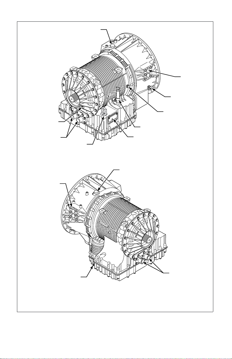
OUTPUT SPEED
SENSOR
COOLER PORTS
FEEDTHROUGH
HARNESS CONNECTOR
MOUNTING PAD
(BOTH SIDES)
BREATHER
MOUNTING
PAD
INPUT SPEED
SENSOR
TURBINE SPEED
SENSOR
FILL TUBE AND DIPSTICK
NAMEPLATE
BREATHER
MAIN-PRESSURE TAP
Figure 4. Typical 4000 MH Series Transmission
(Allison 4
th
Generation Controls)
11
COOLER PORTS
V06342.01.00
Page 13

A BRIEF DESCRIPTION OF THE ALLISON MOTORHOME SERIES TRANSMISSIONS
Included in the Allison On-Highway Transmission family are the Motorhome
Series transmissions. The transmissions described in this manual include:
th
• WTEC III Controls or Allison 4
Generation Controls
• A torque converter with lockup and torsion damper
• Three planetary gear sets
Motorhome Series transmissions may contain an integral retarder or a provision to
mount a Power Takeoff (PTO).
ELECTRONIC CONTROL SYSTEM
All Motorhome Series transmissions come standard with WTEC III Controls or
Allison 4
connected by OEM-furnished wiring harnesses. The five major components are:
The TCM/ECU receives information from the following:
The TCM/ECU processes information and then sends signals to actuate specific
solenoids located in the control valve module. These solenoids control both
oncoming and offgoing clutch pressures to provide closed-loop shift control by
matching input rpm during a shift to a desired profile programmed into the
TCM/ECU.
th
Generation Controls. These systems consist of five major components
• Transmission Control Module (TCM) or Electronic Control Unit (ECU)
• Three speed sensors
• Remote shift selector
• Control module (which contains solenoid valves, a pressure switch, and an
optional oil level sensor)
• Engine Electronic Control Module (ECM) or Engine Throttle Position
Sensor (TPS), if installed
• Throttle position sensor, if installed
• Speed sensors
• Pressure switch
• Shift selector
12
Page 14
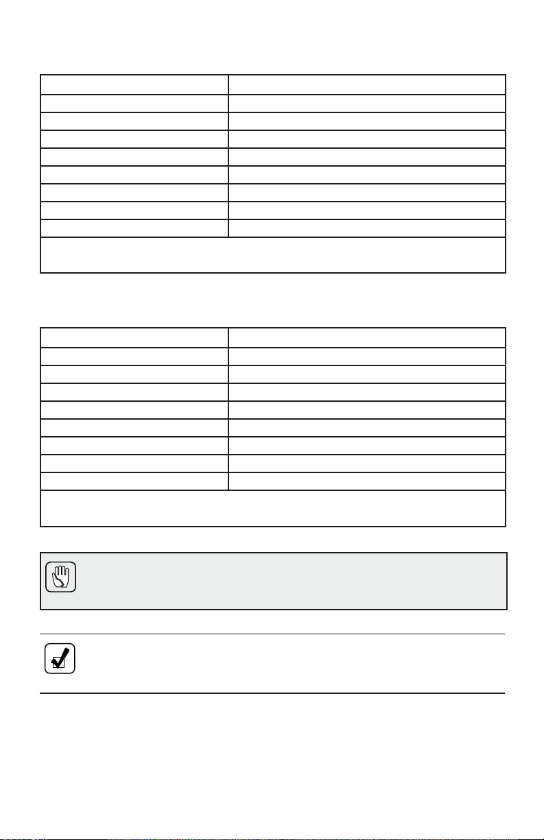
A feature of both Allison 4thGeneration Controls and WTEC III controls is
“autodetect.” Autodetect is active within the first several engine starts, depending
upon the component or sensor being detected. These engine start cycles begin
when the transmission is installed during vehicle manufacture. Autodetect searches
for the presence of the following transmission components or data inputs:
Transmission Components
Retarder Present, Not Present
Oil Level Sensor (OLS) Present, Not Present
Throttle Analog, J1587, J1939
Engine Coolant Temperature Analog, J1939, J1587
Seek help from the nearest Allison Transmission service outlet when any of the
above components are present, but are not responding properly.
Another feature of the Motorhome Series transmission is its ability to adapt or
“learn” as it operates. Each shift is measured electronically, stored, and used by
the TCM/ECU to adapt or “learn” the optimum control for future shifts.
NOTE: Allison 4thGeneration Controls and WTEC III Controls are
designed and manufactured to comply with all FCC and other guidelines
regarding radio frequency interference/electromagnetic interference
(RFI/EMI) for transportation electronics. Manufacturers, assemblers, and
installers of radio-telephone or other two-way communication radios
have the sole responsibility to correctly install and integrate those
devices into Allison Motorhome Series transmission-equipped vehicles
to customer satisfaction.
The TCM/ECU is programmed to provide the most suitable operating
characteristics for a specific application. This manual does not attempt to describe
all of the possible combinations. The information contained herein describes only
the operating characteristics most frequently requested by the vehicle
manufacturer.
TORQUE CONVERTER
The torque converter consists of the following four elements:
• Pump—input element driven directly by the engine
• Turbine—output element hydraulically driven by the pump
• Stator—reaction (torque multiplying) element
• Lockup Clutch—mechanically couples the pump and turbine when engaged;
controlled by TCM/ECU
13
Page 15

When the pump turns faster than the turbine, the torque converter is multiplying
torque. When the turbine approaches the speed of the pump, the stator starts to
rotate with the pump and turbine. When this occurs, torque multiplication stops
and the torque converter functions as a fluid coupling.
The lockup clutch is located inside the torque converter and consists of the
following elements:
• Piston and backplate—driven by the engine
• Clutch plate/damper (located between the piston and the
backplate)—splined to the converter turbine
The lockup clutch/torsional damper is engaged and released in response to
electronic signals from the TCM/ECU. Lockup clutch engagement provides a
direct drive from the engine to the transmission gearing. This eliminates converter
slippage and maximizes fuel economy and vehicle speed. The lockup clutch
releases at lower speeds or when the TCM/ECU detects conditions requiring it to
be released.
The torsional damper absorbs engine torsional vibration to prevent transmitting
vibrations through the powertrain.
PLANETARY GEARS AND CLUTCHES
A series of three helical planetary gear sets and shafts provides the mechanical
gear ratios and direction of travel for the vehicle. The planetary gear sets are
controlled by five multiplate clutches that work in pairs to produce up to six
forward speeds and one reverse speed. The clutches are applied and released
hydraulically in response to electronic signals from the TCM/ECU to the
appropriate solenoids.
COOLER CIRCUIT
The transmission fluid is cooled by an integral (transmission-mounted) or
remote-mounted oil cooler. Connections to the cooling circuit are located at the
front or rear of the transmission to facilitate installation of remote cooler lines. On
retarder models, only the rear cooler ports may be used. The integral cooler is
mounted on the lower rear portion of the transmission, replacing the remote cooler
manifold. Integral cooler oil ports are internal requiring coolant to be routed to
and from the cooler.
A new feature has been added on all retarder-equipped transmissions. The retarder
housing now allows addition of either a remote or integral cooler for transmission
sump fluid in addition to retarder out fluid. A by-pass cover is placed over the
sump cooling ports when the provision is not used. The sump cooler ports are
located on the lower right rear face of the retarder housing (refer to Figure 1
through Figure 4).
14
Page 16

RETARDER
The self-contained retarder is at the output of the transmission and consists of a
vaned rotor which rotates in a vaned cavity. The rotor is splined to and driven by
the output shaft. An external accumulator holds transmission fluid until the
retarder is activated. When the retarder is activated, the fluid in the accumulator is
pressurized by the vehicle air system and directed into the retarder cavity. The
interaction of the fluid with the rotating and stationary vanes causes the retarder
rotor and output shaft to reduce speed, slowing the vehicle or limiting speed on a
downhill grade. Refer to USING THE HYDRAULIC RETARDER for additional
information.
When the retarder is deactivated, the retarder cavity is evacuated and the
accumulator is recharged with fluid.
15
Page 17
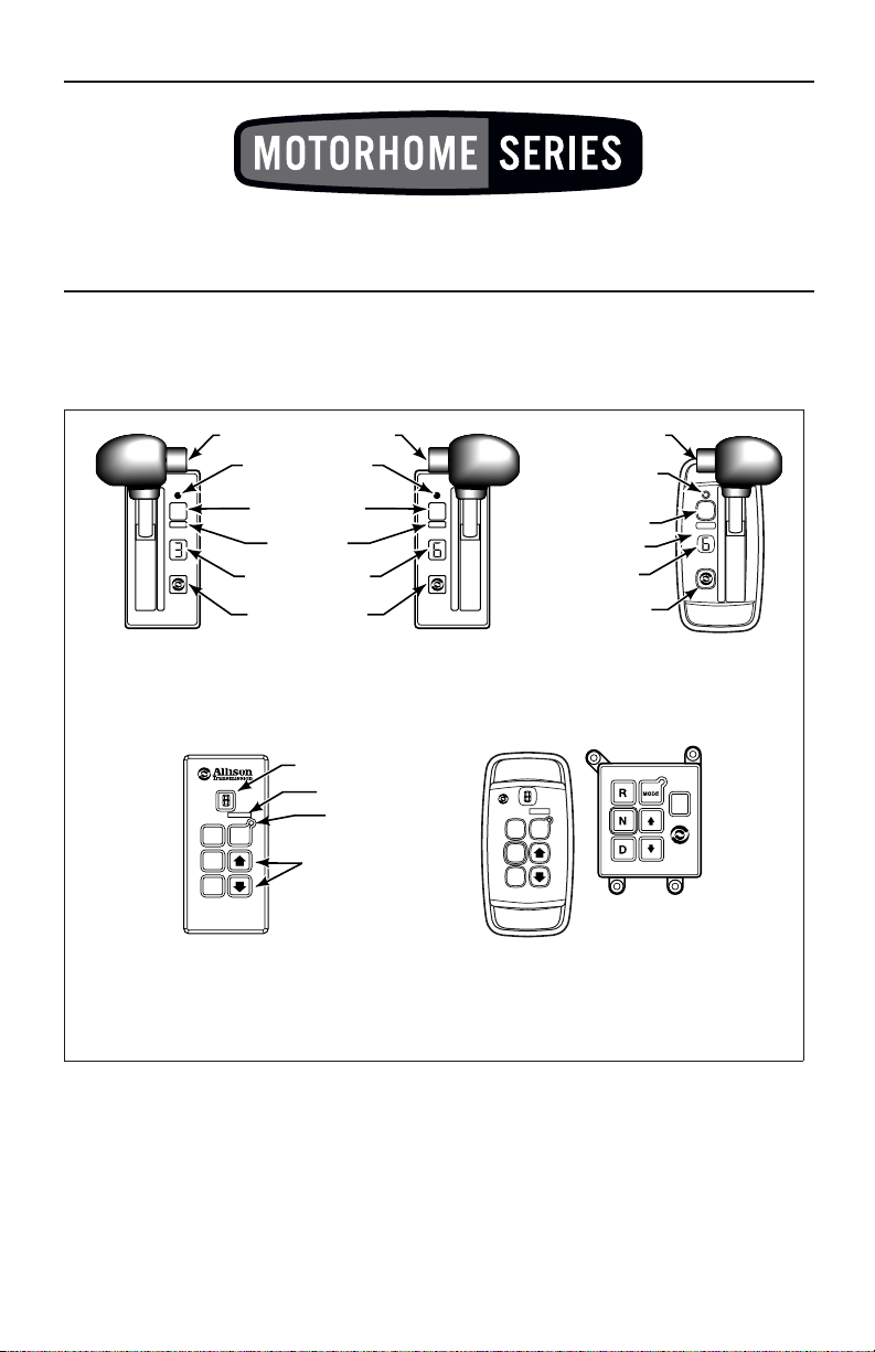
SHIFT SELECTORS
DESCRIPTION OF AVAILABLE TYPES
1
MODE
2
3
4
5
D
N
R
SIX-SPEED,
LEFT-HAND
LEVER
SELECTOR
HOLD OVERRIDE BUTTON
MODE INDICATOR
(LED)
MODE BUTTON
MODE ID
DIGITAL DISPLAY
*
DISPLAY MODE/
DIAGNOSTIC BUTTON
SIX-SPEED,
RIGHT-HAND
LEVER SELECTOR
WITH REVERSE TO FRONT
DIGITAL DISPLAY
*
R
MODE
N
D
5
4
3
2
1
HOLD OVERRIDE
BUTTON
MODE INDICATOR
(LED)
MODE BUTTON
MODE ID
DIGITAL DISPLAY
*
DISPLAY MODE/
DIAGNOSTIC BUTTON
MODE ID
MODE
R
N
D
MODE
INDICATOR (LED)
Push simultaneously
to enter diagnostic
mode and fluid
MODE
R
N
D
level check
PUSHBUTTON SELECTORS
NOTE:
Number displayed is highest forward range available in selected position.
*
Visually check to confirm range selected. If display is flashing, shift is inhibited.
R
MODE
N
D
5
4
3
2
1
CONTOURED
VERSION
V07343.01.02
Figure 5. WTEC III Shift Selectors
16
Page 18
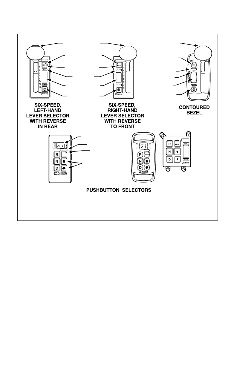
6
1
DIAGNOSTIC BUTTON
HOLD OVERRIDE
BUTTON
MODE INDICATOR
(LED)
MODE BUTTON
MODE ID
DIGITAL DISPLAY
DISPLAY MODE
*
HOLD OVERRIDE
BUTTON
MODE INDICATOR
6
1
MODE BUTTON
DIGITAL DISPLAY
DISPLAY MODE
DIAGNOSTIC BUTTON
(LED)
MODE ID
*
6
1
DIGITAL DISPLAY
MODE ID
MODE
The first number displayed is highest forward range available and second number is range
NOTE:
*
attained in selected position.
Visually check to confirm range selected. If display is flashing, shift is inhibited.
MODE
INDICATOR (LED)
Push simultaneously
to enter diagnostic
mode and fluid
level check
*
6
1
V07343.03.01
Figure 6. Allison 4thGeneration Controls Shift Selectors
INTRODUCTION
Vehicle manufacturers may choose different types of shift selectors for their
vehicles. The shift selector in your Allison-equipped vehicle will be similar to one
of the pushbutton or lever styles shown above.
With an Allison-equipped vehicle, it is not necessary to select the right moment to
upshift or downshift during changing road and traffic conditions. The Allison
Motorhome Series transmission does it for you. However, knowledge of the shift
selector positions, available ranges, and when to select them, make vehicle control
and your job even easier. Select lower ranges when descending long grades (with
or without retarder) to reduce wear on service brakes. Refer to the Range
Selection table at the end of this section for related information.
17
Page 19

LEVER SHIFT SELECTOR
General Description. The lever shift selector (refer to Figure 5 and Figure 6) is
an electro-mechanical control. Typical lever positions are:
• R (Reverse)
• N (Neutral)
• D (Drive)
• Some number of lower forward range positions
Motorhome Series transmissions can be programmed to have four, five,orsix
forward ranges. Shift selector positions should agree with the programming of the
TCM/ECU unit.
The lever selector includes the following:
• HOLD OVERRIDE button
• MODE button
• Digital display
• DISPLAY MODE/DIAGNOSTIC button
HOLD OVERRIDE Button. The lever shift selector has three locked positions to
prevent accidentally selecting R (Reverse), N (Neutral), or D (Drive). Select
R (Reverse), N (Neutral), or D (Drive) by pressing the HOLD OVERRIDE
button and moving the lever to the desired position. Once D (Drive) is selected,
lower forward range positions may be selected without pressing the
HOLD OVERRIDE button.
MODE Button. The MODE button can allow the driver to enable a secondary
shift schedule, PTO, or other special functions that have been programmed into
the TCM/ECU unit at the request of the OEM. For example, a motorhome OEM
may have provided a secondary shift schedule for improved fuel economy. The
name of the special function (ECONOMY) appears on the MODE ID label
adjacent to the MODE button. Pressing the MODE button activates the
ECONOMY shift schedule and illuminates the MODE INDICATOR (LED).
When the Diagnostic Display Mode has been entered, the MODE button is used
to view and toggle through diagnostic code information. After viewing the first
diagnostic code which appears in the digital display, press the MODE button to
view the 2
and 5
nd
th
diagnostic code logged. Repeat this procedure to view the 3rd,4th,
code positions. The code displayed is active if the MODE INDICATOR
(LED) is illuminated.
NOTE: Visually check the digital display whenever the lever is moved
to be sure the range selected is shown. N should appear in the digital
displayiftheN (Neutral) button is pressed.
18
Page 20

Digital Display. During normal operation, if D (Drive) is selected, the digital
display shows the highest forward range attainable for the shift schedule in use.
Abnormal operation is indicated by the WTEC III digital display as follows:
• When all segments of the digital display are illuminated for more than
12 seconds, the ECU did not complete initialization.
• When the digital display is blank, there is no power to the selector.
• When the display shows a “
\
/\” (cateye), a selector-related fault code has
been logged.
• Conditions which illuminate the CHECK TRANS light disable the shift
selector and the digital display displays the range actually attained. For a
detailed explanation, refer to the CHECK TRANS LIGHT paragraph in the
DRIVING TIPS section.
Abnormal operation is indicated by the Allison 4
th
Generation Controls digital
display as follows:
• When all segments of the digital display are illuminated, the shift selector
did not complete initialization.
• When both digital displays remain blank for 10 seconds after initialization
and then show a “
\
/\” (cateye), the shift selector is unable to communicate
with the TCM or has experienced an internal fault.
• When the display shows a “
\
/\” (cateye), a selector-related fault code has
been logged.
• Conditions which illuminate the CHECK TRANS light disable the shift
selector. The SELECT digit is blank and the MONITOR digit displays the
range actually attained. For a detailed explanation, refer to the CHECK
TRANS LIGHT paragraph in the DRIVING TIPS section.
The transmission will not shift into range if a CHECK TRANS code is active.
When the display shows R or D has been requested and the display is flashing,
the requested range has not been achieved due to an inhibit function.
Some inhibit functions are vehicle-related and do not result in diagnostic codes.
Some examples are mentioned in the Range Selection tables at the end of this
Section.
Check for active codes if no other inhibit function has been located. Once
D (Drive) is attained, the transmission will shift into the lowest range programmed
for the D (Drive) position, usually first-range.
Display Mode/Diagnostic Button. The DISPLAY MODE/DIAGNOSTIC button
allows access to optional fluid level check information and diagnostic code
information. Press the DISPLAY MODE/DIAGNOSTIC button once to obtain
transmission fluid level information and a second time to obtain diagnostic code
information.
19
Page 21
PUSHBUTTON SHIFT SELECTOR
General Description. The pushbutton shift selector (refer to Figure 5 and
Figure 6) has the following:
• R (Reverse)—Press this button to select Reverse.
• N (Neutral)—Press this button to select Neutral.
• D (Drive)—Press this button to select Drive. The highest forward range
available will appear in the digital display window. The transmission will
start out in the lowest available forward range and advance automatically to
the highest range.
• ↑ (Up) Arrow—Press the ↑ (Up) Arrow when in DRIVE to request the
next higher range. Continuously pressing the ↑ (Up) Arrow will request the
highest range available.
• ↓ (Down) Arrow—Press the ↓ (Down) Arrow when in DRIVE to request
the next lower range. Continuously pressing the ↓ (Down) Arrow will
request the lowest range available.
• MODE Button and Display Mode/Diagnostic Button—This is the same
function as described previously in the LEVER SHIFT SELECTOR
paragraph, MODE Button paragraph.
NOTE: The oil level sensor is a standard feature on Motorhome Series
transmissions. Fluid level information is displayed after pressing both
the ↑ (Up) and ↓ (Down) arrow buttons simultaneously. Simultaneously
press both buttons again to obtain diagnostic data.
Refer to the Care And Maintenance section, FLUID LEVEL CHECK USING
PUSHBUTTON OR LEVER SHIFT SELECTOR for more information about fluid
level data. Refer to the Driving Tips section, DIAGNOSTIC CODES and
DIAGNOSTIC CODE DISPLAY PROCEDURE, for more information about
diagnostic codes and display procedure.
20
Page 22
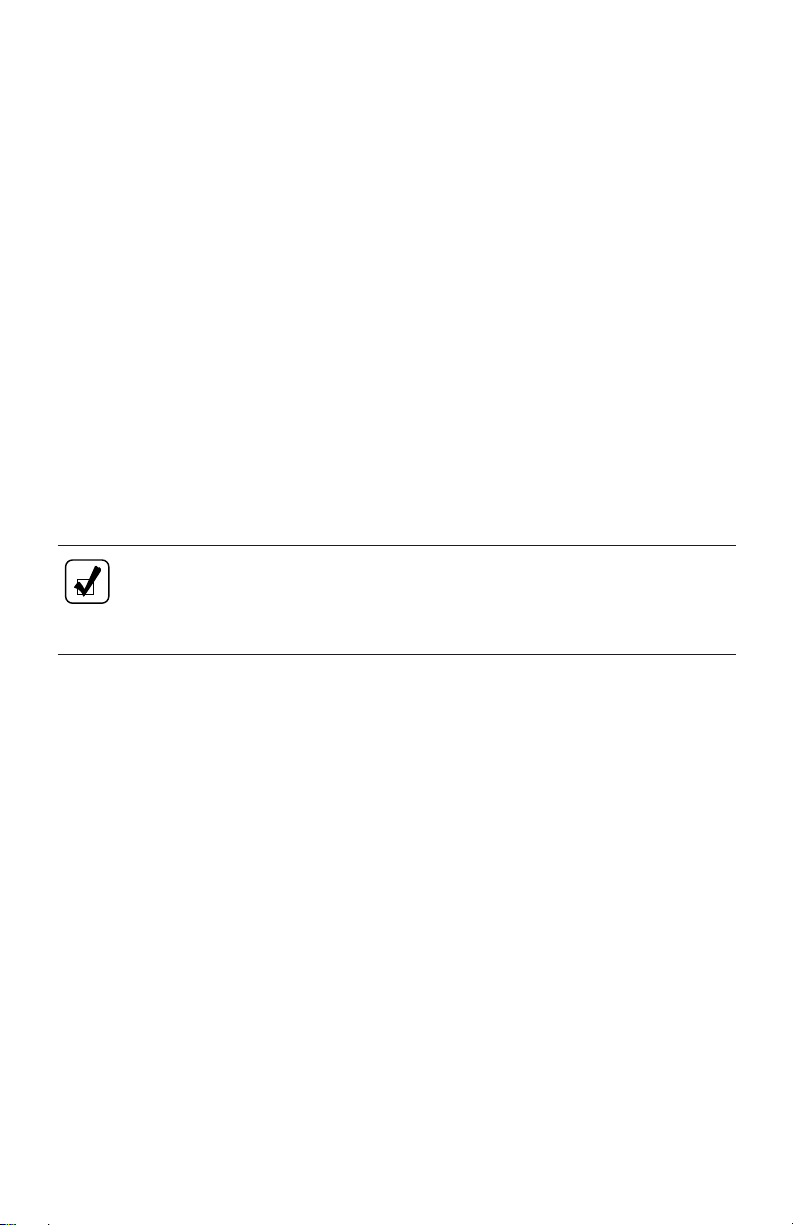
RANGE SELECTION
R
MODE
R
N
D
N
D
MODE
R
MODE
N
D
5
4
3
2
1
R
MODE
N
D
5
4
3
2
1
V07344
Figure 7. Typical Motorhome Series Shift Selectors
(WTEC III Controls)
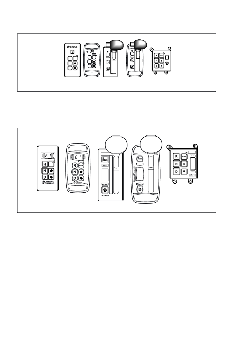
MODE
Figure 8. Typical Motorhome Series Shift Selectors
(Allison 4
R
N
D
6
5
4
1
3
2
1
th
Generation Controls)
6
1
V07344.01.00
6
1
21
Page 23

PUSHBUTTON AND LEVER SHIFT SELECTORS
WITH DIGITAL DISPLAY
Description of Available Ranges (refer to Figure 7 and Figure 8)
WARNING: If you leave the vehicle and the engine is running,
the vehicle can move unexpectedly and you or others could be
injured. If you must leave the engine running, do not leave the
vehicle until you have completed all of the following
procedures:
1. Put the transmission in N (Neutral).
2. Be sure the engine is at low idle (500–800 rpm).
3. Apply the parking brakes and emergency brake and make
sure they are properly engaged.
4. Chock the wheels and take any other steps necessary to
keep the vehicle from moving.
WARNING: R (Reverse) may not be attained due to an active
inhibitor. Always apply the service brakes when selecting
R (Reverse) to prevent unexpected vehicle movement and
because a service brake inhibit may be present. When “R” is
flashing, it indicates the shift to R (Reverse) is inhibited.
Check for active diagnostic codes if R (Reverse) is not
attained. See DOWNSHIFT AND DIRECTION CHANGE
INHIBITOR FEATURE in the DRIVING TIPS section.
CAUTION: Do not idle in R (Reverse) for more than
five minutes. Extended idling in R (Reverse) can cause
transmission overheating and damage. Always select N (Neutral)
whenever time at idle exceeds five minutes.
NOTE: Visually check the digital display window whenever a
button is pushed or the lever is moved to be sure the range selected
isshown(i.e.,iftheN (Neutral) button is pressed, “N” should
appear in the digital display). A flashing display indicates the range
selected was not attained due to an active inhibit.
22
Page 24
PUSHBUTTON AND LEVER SHIFT SELECTORS
WITH DIGITAL DISPLAY
(cont’d)
Description of Available Ranges (refer to Figure 7 and Figure 8)
R Completely stop the vehicle and let the engine return to idle before
shifting from a forward range to R (Reverse) or from R (Reverse)
to a forward range. The digital display will display “R” when
R (Reverse) is selected.
WARNING: When starting the engine, make sure the service
brakes are applied. Failure to apply the service brakes can
result in unexpected vehicle movement.
WARNING: Vehicle service brakes, parking brake, or
emergency brake must be applied whenever N (Neutral) is
selected to prevent unexpected vehicle movement. Selecting
N (Neutral) does not apply vehicle brakes, unless an auxiliary
system to apply the parking brake is installed (see the
Operator’s Manual for the vehicle).
WARNING: If you let the vehicle coast in N (Neutral), there is
no engine braking and you could lose control. Coasting can also
cause severe transmission damage. To help avoid injury and
property damage, do not allow the vehicle to coast in
N (Neutral).
N Use N (Neutral) when starting the engine, to check vehicle
accessories, and for extended periods of engine idle operation
(longer than five minutes). For vehicles equipped with the
pushbutton selector, N (Neutral) is selected by the ECU during
start-up. For vehicles equipped with the lever selector, the vehicle
will not start unless N (Neutral) has been selected. If the vehicle
starts in any range other than N (Neutral), seek service
immediately. N (Neutral) is also used during stationary operation of
the power takeoff (if the vehicle is equipped with a PTO). The
digital display will show “N” when N (Neutral) is selected. Always
select N (Neutral) before turning off the vehicle engine.
23
Page 25
PUSHBUTTON AND LEVER SHIFT SELECTORS
WITH DIGITAL DISPLAY
(cont’d)
Description of Available Ranges (refer to Figure 7 and Figure 8)
WARNING: D (Drive) may not be attained due to an active
inhibitor. Always apply the service brakes when selecting
D (Drive) to prevent unexpected vehicle movement and
because a service inhibit may be present. When “D” is
flashing, it indicates the shift to D (Drive) is inhibited. Check
for active diagnostic codes if D (Drive) is not attained. See
DOWNSHIFT AND DIRECTION CHANGE INHIBITOR
FEATURE in the DRIVING TIPS section.
CAUTION: Do not idle in D (Drive) or any forward range for
more than five minutes. Extended idling in D (Drive) can cause
transmission overheating and damage. Always select N (Neutral)
whenever time at idle exceeds five minutes.
NOTE: Turn off the vehicle HIGH IDLE switch, if present, before
shifting from N (Neutral) to D (Drive) or R (Reverse). D (Drive)
or R (Reverse) will not be attained unless the shift is made with
the engine at idle. Also, be aware of other interlocks that would
prevent attaining D (Drive) or R (Reverse). Examples are
“wheelchair lift not stored” and “service brakes not applied”
(service brake interlock present).
D The transmission will initially attain first-range when D (Drive) is
selected (except for those units programmed to start in
second-range). As vehicle speed increases, the transmission will
upshift automatically through each range. As the vehicle slows, the
transmission will downshift automatically through each range. The
digital display will show the highest range available in D (Drive).
WARNING: The transmission incorporates a hold feature to
prohibit upshifting above the range selected during normal
driving. For downhill operation, select a lower transmission
range. If the engine governed speed is exceeded in the held
range, however, the transmission will upshift to the next higher
range to prevent engine damage. To avoid injury and/or property
damage due to loss of vehicle control, use the vehicle brakes to
prevent exceeding engine governed speed in the held range.
24
Page 26

PUSHBUTTON AND LEVER SHIFT SELECTORS
WITH DIGITAL DISPLAY
(cont’d)
Description of Available Ranges (refer to Figure 7 and Figure 8)
6*
5*
4*
3
2
Lower ranges provide greater engine braking for going down
grades (the lower the range, the greater the braking effect).
Occasionally, it may be desirable to restrict automatic shifting to a
lower range because of:
• Road conditions.
• Load.
• Traffic conditions.
• Etc.
The pushbutton shift selector arrow buttons access individual
forward ranges. Push the ↑ (Up) or ↓ (Down) arrow for the desired
range. The digital display shows the range chosen. Even though a
lower range is selected, the transmission may not downshift until
vehicle speed is reduced (this prevents excessive engine speed in
the lower range).
1 First-range provides the vehicle with its maximum driving torque
and engine braking effect. Use first-range when:
• Pulling through mud and deep snow.
• Maneuvering in tight spaces.
• Driving up or down steep grades.
For vehicles equipped with the pushbutton selector, push the
↓ (Down) arrow until first-range appears in the select window.
* Actual ranges available depend on programming by vehicle manufacturer.
25
Page 27
DRIVING TIPS
CHECK TRANS LIGHT
The electronic control system is programmed to inform the operator of a problem
with the transmission system and automatically take action to protect the operator,
vehicle, and transmission. When the Electronic Control Unit (ECU) or the
Transmission Control Module (TCM) detects a problem condition, the TCM/ECU:
• Restricts shifting.
• Illuminates the CHECK TRANS light on the instrument panel.
• Registers a diagnostic code.
NOTE: For some problems, diagnostic codes may be registered without
the TCM/ECU activating the CHECK TRANS light. Your Allison
Transmission authorized service outlet should be consulted whenever
there is a transmission-related concern. They have the equipment to
check for diagnostic codes and to correct problems which arise.
Each time the engine is started, the CHECK TRANS light will illuminate, then
turn off after a few seconds. This momentary lighting is to show that the status
light circuits are working properly. If the CHECK TRANS light does not
illuminate during ignition, or if the light remains on after ignition, the system
should be checked immediately.
Continued illumination of the CHECK TRANS light during vehicle operation
(other than start-up) indicates that the TCM/ECU has signaled a diagnostic code.
Illumination of the CHECK TRANS light is accompanied by a flashing display
from the shift selector. The shift selector display will show the actual range
attained and the transmission will not respond to shift selector requests.
Indications from the shift selector are provided to inform the operator the
transmission is not performing as designed and is operating in the “limp home”
mode with reduced capabilities. Before turning off the ignition, the transmission
may be operated for a short time in the selected range in order to “limp home” for
26
Page 28
service assistance. Service should be performed immediately in order to minimize
the potential for damage to the transmission.
When the CHECK TRANS light comes on and the ignition switch is turned off,
the transmission will remain in N (Neutral) until the condition causing the
CHECK TRANS light is corrected.
Generally, while the CHECK TRANS light is on, upshifts and downshifts will be
restricted and direction changes will not occur. Lever and pushbutton shift
selectors do not respond to any operator shift requests while the CHECK
TRANS light is illuminated. The lockup clutch is disengaged when transmission
shifting is restricted or during any critical transmission malfunction.
DIAGNOSTIC CODES
See detailed information in the DIAGNOSTICS section.
ACCELERATOR CONTROL
WARNING: To help avoid injury or property damage caused by sudden
movement of the vehicle, do not make shifts from N (Neutral) to
D (Drive) or R (Reverse) when the throttle pedal is depressed. If you
shift while the throttle pedal is depressed too far, the transmission will
only engage if the throttle pedal is released in the next three seconds.
This may cause a sudden movement of the vehicle. Leaving the throttle
pedal depressed longer than three seconds causes the transmission to
remain in N (Neutral). Avoid this condition by making shifts from
N (Neutral) to D (Drive) or R (Reverse) only when the throttle is
closed.
The position of the accelerator pedal influences when automatic shifting occurs.
An electronic throttle position signal tells the TCM/ECU how much the operator
has depressed the pedal. When the pedal is fully depressed, upshifts will occur
automatically at high engine speeds. A partially depressed position of the pedal
will cause upshifts to occur at lower engine speeds. Excessive throttle position
affects directional changes—shifts from N (Neutral) to D (Drive) or R (Reverse).
DOWNSHIFT AND DIRECTION CHANGE INHIBITOR FEATURE
NOTE: Turn off the vehicle HIGH IDLE switch, if present, before
shifting from N (Neutral) to D (Drive) or R (Reverse). The shift from
N (Neutral) to D (Drive) or R (Reverse) is inhibited when engine speed
is above idle.
27
Page 29

There is no speed limitation on upshifting, but there is a limitation on
downshifting and for shifts that cause a direction change such as
D (Drive)-to-R (Reverse) or R (Reverse)-to-D (Drive).
Manual range downshifts will not occur until a calibration output speed (preset) is
reached. When a range downshift is manually selected and the transmission output
speed is above the calibration speed, the transmission will stay in the range it was
in even though a lower range was requested. Apply the vehicle service brakes or a
retarding device to reduce the transmission output speed to the calibration speed
and then the shift to the lower range will occur.
Directional shifts, D (Drive)-to-R (Reverse) or R (Reverse)-to-D (Drive), will not
occur if selected when throttle position, engine speed, or transmission output
speed is above the calibration limit for a calibration time period. The current
calibration time period for engine speed is 0.5 seconds and for throttle position
and output speed is three seconds.
Shifts from N (Neutral)-to-D (Drive) or N (Neutral)-to-R (Reverse) are also
inhibited when the TCM/ECU has been programmed (by input/output function) to
detect that auxiliary equipment is in operation and the shift should not be allowed.
When directional change shifts are inhibited, the TCM/ECU will put the
transmission in N (Neutral) and the digital display, if present, will flash the letter
of the range selected (D or R). To reselect D (Drive) or R (Reverse) when engine
throttle, engine speed, and transmission output speed are below the calibration
value:
• Pushbutton selector—Press the desired pushbutton again.
• Lever selector—Move the lever to N (Neutral) and then to the desired
range.
When a direction change shift is requested and engine throttle, engine speed, and
transmission output speed drop below the calibration value during the calibration
time interval, the shift to D (Drive) or R (Reverse) will occur.
For example, if the transmission output speed was just above the calibration limit
when R (Reverse) was selected, but dropped below the limit during the next three
seconds, the shift to R (Reverse) would occur (assuming the engine was at idle
and the throttle was closed).
28
Page 30

USING THE ENGINE TO SLOW THE VEHICLE
WARNING: To avoid loss of control, use a combination of
downshifting, braking, and other retarding devices. Downshifting to a
lower transmission range increases engine braking and can help you
maintain control. The transmission has a feature to prevent automatic
upshifting above the lower range selected. However, during downhill
operation, if engine governed speed is exceeded in the lower range, the
transmission will upshift to the next higher range to prevent engine
damage. This will reduce engine braking and could cause a loss of
control. Apply the vehicle brakes or other retarding device to prevent
exceeding engine governed speed in the lower range selected.
Engine braking provides good speed control for going down grades. When the
vehicle is heavily loaded, or the grade is steep, it may be desirable to preselect a
lower range before reaching the grade. If engine-governed speed is exceeded, the
transmission will upshift automatically to the next range.
To use the engine as a braking force, select the next lower range. If the vehicle is
exceeding the maximum speed for this range, use the service brakes and/or
retarder to slow the vehicle. When a lower speed is reached, the TCM/ECU will
automatically downshift the transmission.
USING THE HYDRAULIC RETARDER
WARNING: DO NOT USE THE RETARDER DURING INCLEMENT
WEATHER OR WHEN ROAD SURFACES ARE SLIPPERY.
De-energize the retarder at the master control switch.
To help avoid injury or property damage caused by loss of vehicle
control, be ready to apply vehicle brakes or other retarding device if the
transmission retarder does not apply. If a retarder is present but is not
detected by “autodetect”, the retarder will not function. Be sure to check
for proper retarder function periodically. Whenever the retarder does not
apply, seek service help immediately.
On vehicles which have the primary retarder control based upon closed
throttle position, brake pedal position, or brake apply pressure, always
manually disable the retarder controls during inclement weather or
slippery road conditions.
Regardless of the type of Allison retarder controls on your vehicle, the following
safety features are common to each configuration:
• The retarder can be disabled when inclement weather or slippery road
conditions are present.
29
Page 31

• Vehicle brake lights should always be on when the retarder is applied
(periodically verify that they are working).
• Anti-lock brake systems send a signal to the transmission TCM/ECU to
indicate that the brake system is activated.
NOTE: The retarder is automatically disabled and the lockup clutch is
disengaged whenever the vehicle anti-lock brake system (ABS) is active.
However, in case the ABS system malfunctions, it is recommended that
the retarder enable switch, if present, be disabled.
A hydraulic retarder is available on all of the models covered in this manual. The
retarder is activated and controlled in various ways. The control depends upon the
vehicle type and particular duty cycle. Both manual and automatic controls are
available. Automatic controls are applied by the TCM/ECU. In Allison 4
th
Generation Control Systems, the TCM may also activate or limit retarder
operation in response to torque speed control or electronic retarder control
messages received on the vehicle’s J1939 Data Link. Some types of controls and
the amount of retarder application are shown in the Types of Retarder Control
table that follows.
The presence of a retarder must be “autodetected” as part of Allison 4
th
Generation Controls and the WTEC III control system.
NOTE: If your transmission has a retarder but it is not functioning, it
may not have been “autodetected” during vehicle manufacture. Go
immediately to your nearest Allison Transmission service outlet to have
“autodetect” reset or the retarder enabled using the Allison DOC™ For
PC–Service Tool.
NOTE: When reduced retarder performance is observed, be sure the
transmission fluid level is within the operating band on the dipstick
(refer to Figure 11). Low fluid level is a common cause for retarder
performance complaints.
NOTE: The retarder requires about one second to reach full capacity
requested. Be sure to anticipate this delay when using the retarder.
Anticipation will prevent unnecessary service brake applications during
non-emergency stops.
30
Page 32

Types of Retarder Control
Type Description Amount of Application
Manual Separate apply
Zero to Full apply
pedal
Hand lever * Six levels based on lever position
Automatic Auto “Full On” * “Full On” when closed throttle sensed
Brake Pressure
Apply**
Pedal Position ** Special brake
J1939 Data Link Digital message
Single pressure
switch
Three pressure
switches
pedal
Off or “Full On” (based on brake
pressure)
1
/3,2/3, or “Full On” (based on brake
pressure)
1
/3,2/3,or“FullOn”(basedonpedal
position)
Zero to Full Apply
from engine
controller
Combinations of
the above
systems **
Auto “half-on”
plus pressure
switch *
Auto “
1
/3on” plus
two pressure
Half capacity at closed throttle or
“Full On” with brake pressure
1
/3, capacity at closed throttle or2/
and “Full On” with brake pressure
3
switches *
Hand lever plus
pressure switch *
Foot pedal plus
pressure switch
Hand lever plus
interface for
special pedal *
6 levels of modulation with lever, or
“Full On” with brake pressure
Full modulation with separate pedal,
or “Full On” with brake pressure
6 levels of modulation with lever, or 3
levels of modulation based on pedal
position
* These control systems may apply the retarder at high speed on grades when
the vehicle has road speed limiting and the retarder is enabled.
** For retarder apply systems integrated with the service brake system, the
retarder is most effective when applied with light brake pedal pressure for
1–2 seconds to allow the retarder to fully charge. Added pedal pressure can
be applied when more aggressive braking is desired.
31
Page 33

NOTE: When the transmission fluid or engine water temperature
(engine water is an OEM option) exceeds programmed limits, retarder
capacity is automatically gradually reduced to minimize or avoid
possible system overheating.
Contact your vehicle manufacturer to understand how the retarder controls have
been integrated into your vehicle.
CAUTION: Observe the following cautions when driving a vehicle
equipped with a retarder:
• THE RETARDER WORKS ONLY WHEN THE ENGINE IS AT
CLOSED THROTTLE.
• OBSERVE TRANSMISSION AND ENGINE TEMPERATURE
LIMITS AT ALL TIMES. Select the lowest possible transmission
range to increase the cooling system capacity and total retardation
available.
• In the event of OVERHEATING, DECREASE THE USE OF THE
RETARDER; USE THE SERVICE BRAKES TO SLOW THE
VEHICLE.
• OBSERVE THE RETARDER/SUMP “OVERTEMP” LIGHT to be
sure it responds properly to retarder temperature.
NOTE: Transmission fluid level must be set correctly for highest
retarder effectiveness. As much as 2 liters (2 quarts) too high or too low
can reduce retarder effectiveness and increase transmission temperature.
ADAPTING SHIFTS
When poor shift quality is due to the installation of a new or recalibrated ECU,
use the following procedure to restore good shift quality by completing a
prescribed number of shifts in a relatively short time instead of over several days
of operation.
NOTE: Shift concerns may indicate the transmission has never had the
shifts fully adapted.
The adaptive feature does not function below 100°F transmission sump
temperature. Normal sump temperature is recommended before this procedure is
followed.
Check transmission sump level and assure it is set to “Hot Full” at normal sump
temperature before this procedure is followed.
32
Page 34

All segments of this procedure are to be repeated a minimumof5timesor until
shift quality variation is indistinguishable from shift to shift.
1. From Neutral, with parking brake set and service brakes applied via foot
pedal, select the following sequence: Drive, Neutral, Reverse, Neutral,
Drive, Reverse, Drive, Neutral. Allow each shift to fully complete before
selecting the next shift.
2. Release all brakes and perform this sequence: Wide Open Throttle (WOT)
1–2; once shift is complete, release the throttle to closed and decelerate to
just prior to the Closed Throttle (CT) 2–1 and perform a Step Thru (ST)
2–1 by going to WOT.
3. Continue the process initiated in Step 2 for each Upshift and Downshift
combination available. Example: Wide Open Throttle (WOT) 2–3; once
shift is complete, release the throttle to closed and decelerate to just prior
to the Closed Throttle (CT) 3–2 and perform a Step Thru (ST) 3–2 by
going to WOT. Repeat for the WOT 3–4/ST 4–3, WOT 4–5/ST 5–4,
WOT 5–6/ST 6–5.
4. From a Stop, release vehicle brakes and perform a set of Part Throttle
(PT—50 to 60 percent) Upshifts to the highest attainable range for the
vehicle. Release the throttle to closed and use light vehicle brakes to
decelerate to a stop.
NOTE: If the vehicle is equipped with an output retarder or engine
brake system, these systems should be turned off for this segment.
5. From a Stop, release vehicle brakes and perform Part Throttle (PT—50 to
60 percent) Upshifts to the 3
rd
range. Release the throttle to closed and,
using moderate to heavy vehicle brakes (NOT panic or wheel lock),
decelerate to a stop.
NOTE: Braking should be aggressive but not to the level that would
cause passenger complaints. If the vehicle is equipped with an output
retarder or engine brake system, these systems should be turned off for
this segment.
33
Page 35

6. From a Stop, release vehicle brakes and perform a set of Wide Open
Throttle Upshifts to the highest attainable range for the vehicle. Release
the throttle to Closed and Preselect Down to 1st Range using the shift
selector. Use light vehicle brakes to decelerate to a stop.
7. If the vehicle is equipped with a retarder or engine brake, turn that system
on for this segment. From a Stop, release vehicle brakes and perform a set
of Wide Open Throttle Upshifts to the highest attainable range for the
vehicle. Release the throttle to Closed and, using light vehicle brakes and
the retarder or engine brake, decelerate vehicle to a stop.
NOTE: Allison Transmission does not recommend using the vehicle
brakes to “force” Powered Downshifts (PD, downshifts with the throttle
applied). If grades are available, these should be used to adapt in WOT
and PT Powered Downshifts.
8. Approach the grade in the highest safely attainable range and hold the
throttle steady at WOT and allow the vehicle to perform the Powered
Downshifts as required to ascend the grade.
9. Approach the grade in the highest safely attainable range and hold the
throttle steady at Part Throttle (PT—50 to 60 percent) and allow the
vehicle to perform the Powered Downshifts as required to ascend the
grade.
RANGE PRESELECTION
NOTE: Preselecting during normal operation may result in reduced fuel
economy.
Range preselection means selecting a lower range to match driving conditions
encountered or expect to be encountered. Learning to take advantage of
preselected shifts will give you better control on slick or icy roads and on
downgrades.
Downshifting to a lower range increases engine braking. The selection of a lower
range often prevents cycling between that range and the next higher range on a
series of short up-and-down hills.
COLD WEATHER STARTS
All Motorhome Series transmissions are programmed to restrict full operation until
specific fluid temperatures are reached. Refer to the following table for
temperature restrictions.
34
Page 36

Minimum Fluid Operating Temperatures
CHECK
Sump Fluid Temperature
TRANS Light Operation
–32°C (–25°F) to –7°C (19°F) OFF Neutral, Reverse, Second
–7°C (19°F) OFF Full operation in all ranges
NOTE: When sump temperature is below 10°C (50°F) and transmission
fluidisC4(not DEXRON
®
or TranSynd™), follow these procedures
when making directional shift changes:
• To shift from forward to reverse, select N (Neutral) and then
R (Reverse).
• To shift from reverse to forward, select N (Neutral) and then
D (Drive) or other forward range.
Failure to follow these procedures may cause illumination of the
CHECK TRANS light and the transmission will be restricted to
N (Neutral).
Transmission operation at cold ambient temperatures may require preheating or
the use of a lower viscosity transmission fluid. Refer to RECOMMENDED
AUTOMATIC TRANSMISSION FLUID AND VISCOSITY GRADE in the Care
And Maintenance section.
DRIVING ON SNOW OR ICE
WARNING: Using the retarder on wet or slippery roads may cause loss
of traction on the drive wheels—your vehicle may slide out of control.
To help avoid injury or property damage, turn the retarder enable to
OFF when driving on wet or slippery roads.
NOTE: The retarder is automatically disabled whenever the vehicle
ABS is active. However, in case the anti-lock brake system (ABS)
malfunctions, it is recommended that the retarder enable switch, if
present, be disabled.
If possible, reduce vehicle speed and select a lower range before losing traction.
Select the range that will not exceed the speed expected to be maintained.
Accelerate or decelerate very gradually to prevent the loss of traction. It is very
important to decelerate gradually when a lower range is selected. It is important
that you reach the selected lower range before attempting to accelerate. This will
avoid an unexpected downshift during acceleration.
35
Page 37

ROCKING OUT
WARNING: To help avoid injury or property damage caused by sudden
movement of the vehicle, do not make shifts from N (Neutral) to
D (Drive) or R (Reverse) when the throttle is open. The vehicle will
lurch forward or rearward and the transmission can be damaged. Avoid
this condition by making shifts from N (Neutral) to a forward range or
R (Reverse) only when the throttle is closed and the service brakes are
applied.
CAUTION: DO NOT make N (Neutral) to D (Drive) or directional
shift changes when the engine rpm is above idle. Also, if the wheels are
stuck and not turning, do not apply full power for more than 10 seconds
in either D (Drive) or R (Reverse). Full power for more than 10 seconds
under these conditions will cause the transmission to overheat. If the
transmission overheats, shift to N (Neutral) and operate the engine at
1200–1500 rpm until it cools (2–3 minutes).
If the vehicle is stuck in deep sand, snow, or mud, it may be possible to rock it
out using the following procedure:
1. Shift to D (Drive) and apply steady, light throttle (never full throttle).
2. When the vehicle has rocked forward as far as it will go, apply and hold
the vehicle service brakes.
3. When engine has returned to idle, select R (Reverse).
4. Release the brakes and apply a steady, light throttle allowing the vehicle to
rock in R (Reverse) as far as it will go.
5. Again, apply and hold the service brakes and allow the engine to return to
idle.
This procedure may be repeated in D (Drive) and R (Reverse) if each directional
shift continues to move the vehicle a greater distance. Never make
N (Neutral)-to-D (Drive) or directional shift changes when the engine rpm is
above idle.
HIGH FLUID TEMPERATURE
The transmission is considered to be overheated when any of the following
temperatures are exceeded:
Sump fluid 121°C (250°F)
Fluid to cooler 149°C (300°F)
Retarder out fluid 165°C (330°F)
36
Page 38

If the transmission overheats during normal operations, check the fluid level in the
transmission. Refer to the fluid level check procedures described in the CARE
AND MAINTENANCE section.
CAUTION: The engine should never be operated for more than
10 seconds at full throttle with the transmission in range and the output
stalled. Prolonged operation of this type will cause the transmission fluid
temperature to become excessively high and will cause severe overheat
damage to the transmission.
If the engine temperature gauge indicates a high temperature, the transmission is
probably overheated. Stop the vehicle and check the cooling system. If it appears
to be functioning properly, run the engine at 1200–1500 rpm with the transmission
in N (Neutral). This should reduce the transmission and engine temperatures to
normal operating levels in 2 or 3 minutes. If temperatures do not decrease, reduce
the engine rpm.
If the engine temperature indicates a high temperature, an engine or radiator
problem is indicated. If high temperature in either the engine or transmission
persists, stop the engine and have the overheating condition investigated by
maintenance personnel.
PARKING BRAKE
WARNING: If you leave the vehicle and the engine is running, the
vehicle can move unexpectedly and you or others could be injured. If
you must leave the engine running, DO NOT LEAVE the vehicle until
you have completed all of the following procedures:
• Put the transmission in N (Neutral).
• Be sure the engine is at low idle (500–800 rpm).
• Apply the parking brake and emergency brake and make sure they
are properly engaged.
• Chock the wheels and take other steps necessary to keep the
vehicle from moving.
The parking brake is only intended to secure an unattended vehicle with the
engine ignition OFF. Always maintain the vehicle parking brake system according
to the manufacturer’s specifications. The parking brake may not have sufficient
capacity to restrain a vehicle with the engine running and the transmission in a
forward or reverse-range. When the vehicle is unattended and the engine is in
operation, the transmission must be in N (Neutral) with the brakes fully applied
and the wheels chocked.
37
Page 39

TOWING OR PUSHING
CAUTION: Failure to lift the driving wheels off the road, disconnect
the driveline, or remove the axle shafts before pushing or towing can
cause serious transmission damage.
The engine cannot be started by pushing or towing. Before pushing or towing a
vehicle do one of the following:
• Disconnect the driveline.
• Lift the drive wheels off the road.
• Remove the axle shafts from the drive wheels.
An auxiliary air supply will usually be required to actuate the vehicle brake
system.
When the axle shafts are removed, be sure to cover the wheel openings to prevent
loss of lubricant and entry of dust and dirt.
PRIMARY/SECONDARY SHIFT SCHEDULES
The points at which shifts occur depend upon predetermined speeds and other
operating conditions. A transmission “shift calibration” includes several sets of
shift points which may be used according to current or anticipated operating
conditions. Some shift schedules may be inhibited as a result of operating
conditions, such as engine or transmission fluid temperature. Shift schedules may
be changed using the MODE button (some applications may use a dash-mounted
switch)—which is typically associated with a change in anticipated vehicle
operation.
The TCM includes the capacity for two separate and distinct shift calibrations
(customer-selectable), one for use in “Primary Mode” of operation and one in
“Secondary Mode.”
• Primary—This shift schedule is typically used for all normal vehicle
operations.
• Secondary—This is an alternate shift schedule that the TCM uses upon
request. Not all vehicles will be equipped with a secondary shift schedule.
The request can be interlocked with a vehicle component, or be
operator-controlled using the MODE button.
Your vehicle may have a dash-mounted light that illuminates when the secondary
mode is active.
CRUISE CONTROL OPERATION
Operating an Allison WTEC III Controls or Allison 4thGeneration
Controls-equipped vehicle on cruise control may cause the transmission to shift
38
Page 40

cycle if the cruise control speed setting is set too close to a scheduled shift point.
One of the following actions may eliminate shift cycling:
• Select the secondary shift schedule by pushing the MODE button (refer to
Figure 5 or Figure 6) on the shift selector.
• Select a lower range by pushing the ↓ (Down) arrow or moving the lever
on the shift selector.
• Change the cruise control setting away from the shift point.
Some vehicles equipped with an engine brake and an Allison WTEC III Controls
or Allison 4
th
Generation Controls-equipped transmission will have the engine
brake controlled by the TCM/ECU. This is done so the transmission will
automatically select a lower range when the engine brake is turned on and the
throttle is near idle position.
Operating a vehicle on cruise control with the engine brake turned on and
controlled by the transmission TCM/ECU, may cause an unwanted application of
the engine brake when the cruise control decelerates for downhill grades.
Eliminate this condition by turning off the engine brake while operating the
vehicle on cruise control.
TURNING OFF THE VEHICLE
Always select N (Neutral) prior to turning off the vehicle engine.
39
Page 41

POWER TAKEOFF OPERATION
ENGINE-DRIVEN POWER TAKEOFF (PTO)
CAUTION: Do not exceed the engagement and operational speed limits
imposed on the driven equipment during the operation of the PTO.
Exceeding the speed limits produces high hydraulic pressure in the PTO
that can damage the PTO components. Consult the vehicle
manufacturer’s literature for these speed limits.
If a PTO is present, it will be mounted on either the left side or the right side for
a 3000 MH transmission depending upon the converter housing configuration. The
PTO is located on the left side or top for a 4000 MH Series transmission. The
PTO drive gear is engine-driven and therefore provides direct engine power. The
PTO can be operated when the vehicle is either moving or stopped.
The PTO gear is in constant mesh with the drive gear in the converter housing.
PTOs are either constant drive (output always powered) or clutched drive. The
output of a clutched drive PTO is powered when the PTO clutch is pressurized.
Be sure that the limits for PTO engagement speed and operational speed are not
exceeded. Consult the vehicle manufacturer’s literature for these speed limits.
Also, all Motorhome Series-equipped vehicles with PTO enable have engagement
and operational speed limits programmed into the ECU to help protect PTO
equipment. Some speed limits have default values which are programmed out of
the operating range and will need to be set for your particular PTO duty cycle.
Consult your vehicle manufacturer to see if your transmission has been
programmed and what operational limits have been established.
When the programmed engagement speed is exceeded, the PTO will not engage.
The PTO engagement must be retried after the speed has been reduced. When
operational speeds (either engine or transmission output) are exceeded, the PTO
will deactivate and the PTO engagement process must be repeated.
40
Page 42

CARE AND MAINTENANCE
PERIODIC INSPECTIONS
Allison Motorhome Series transmissions require minimum maintenance. Careful
attention to the fluid level and the connections for the electronic and hydraulic
circuits is most important.
For easier inspection, the transmission should be kept clean. Make regular periodic
inspections and check:
• For loose bolts.
• For leaking fluid around fittings, lines, and transmission openings.
• The condition of the electrical harnesses.
• The engine cooling system for presence of transmission fluid and check the
transmission fluid for presence of coolant, which would indicate a faulty oil
cooler.
• The breather (refer to Figure 1 through Figure 4) to make sure it is clean
and free from dirt or debris.
Report any abnormal condition to your nearest Allison distributor or dealer.
PREVENT MAJOR PROBLEMS
Help Allison 4thGeneration Controls or WTEC III Controls oversee the operation
of the transmission. Minor problems can be kept from becoming major problems
if an Allison Transmission distributor or dealer is notified when one of these
conditions occur:
• Shifting feels odd.
• Transmission leaks fluid.
• Unusual transmission-related sounds (changes in sound caused by normal
engine thermostatic fan cycling, while climbing a long grade with a heavy
load, have been mistaken for transmission-related sounds).
• CHECK TRANS light comes on frequently.
41
Page 43

IMPORTANCE OF PROPER FLUID LEVEL
It is important that the proper fluid level be maintained at all times because the
transmission fluid cools, lubricates, and transmits hydraulic power. If the fluid
level is too low, the converter and clutches do not receive an adequate supply of
fluid. If fluid level is too high, the fluid can aerate. Aerated fluid can cause the
transmission to shift erratically or overheat.
Motorhome Series transmissions have an oil level sensor (OLS) that allows the
operator to obtain an indication of fluid level from the shift selector. However, no
oil level sensor diagnostics take place unless the OLS is “autodetected” by Allison
th
4
Generation Controls or WTEC III Controls.
Frequently check for the presence of oil level diagnostics if the transmission is
known to contain an OLS. If an OLS is not detected during a fixed number of
engine starts, the WTEC III or Allison 4
that no OLS is present. If an OLS is known to be present, but has not been
detected, then troubleshooting of the OLS circuit is required. After the OLS circuit
is repaired, reset “autodetect” or manually select the OLS function using Allison
DOC™ For PC–Service Tool. For detailed troubleshooting procedures refer to the
Troubleshooting Manual. Refer to the SERVICE LITERATURE section for
specific publication numbers.
NOTE: To correctly check the transmission fluid level using the
dipstick, the transmission fluid must be at operating temperature.
The oil level sensor method of checking the fluid level compensates for
transmission fluid temperature between 60°C–104°C (140°F–220°F).
Any temperature below 60°C (140°F) or above 104°C (220°F) will
result in an Invalid for Display condition.
th
Generation Controls system concludes
42
Page 44

FLUID LEVEL CHECK USING PUSHBUTTON OR LEVER SHIFT SELECTOR
1
MODE
2
3
4
5
D
N
R
SIX-SPEED,
LEFT-HAND
LEVER
SELECTOR
HOLD OVERRIDE BUTTON
MODE INDICATOR
(LED)
MODE BUTTON
MODE ID
DIGITAL DISPLAY
*
DISPLAY MODE/
DIAGNOSTIC BUTTON
SIX-SPEED,
RIGHT-HAND
LEVER SELECTOR
WITH REVERSE TO FRONT
DIGITAL DISPLAY
*
R
MODE
N
D
5
4
3
2
1
HOLD OVERRIDE
BUTTON
MODE INDICATOR
(LED)
MODE BUTTON
MODE ID
DIGITAL DISPLAY
*
DISPLAY MODE/
DIAGNOSTIC BUTTON
MODE ID
MODE
R
N
D
MODE
INDICATOR (LED)
Push simultaneously
to enter diagnostic
mode and fluid
MODE
R
N
D
level check
PUSHBUTTON SELECTORS
NOTE:
Number displayed is highest forward range available in selected position.
*
Visually check to confirm range selected. If display is flashing, shift is inhibited.
R
MODE
N
D
5
4
3
2
1
CONTOURED
VERSION
V07343.01.02
Figure 9. WTEC III Controls Shift Selectors and Pushbutton Selectors
The transmission must be equipped with the oil level sensor to be able to read
fluid level information.
NOTE: WTEC III Controls pushbutton and lever selectors display fluid
level diagnostic information one character at a time. Allison 4
th
Generation Controls pushbutton and lever selectors display fluid level
diagnostic information two characters at a time.
1. Park the vehicle on a level surface, shift to N (Neutral), and apply the
parking brake.
2. Pushbutton shift selector—If equipped with an oil level sensor,
simultaneously press the ↑ (Up) and ↓ (Down) arrow buttons.
43
Page 45

6
1
DIAGNOSTIC BUTTON
HOLD OVERRIDE
BUTTON
MODE INDICATOR
(LED)
MODE BUTTON
MODE ID
DIGITAL DISPLAY
DISPLAY MODE
*
HOLD OVERRIDE
BUTTON
MODE INDICATOR
6
1
MODE BUTTON
DIGITAL DISPLAY
DISPLAY MODE
DIAGNOSTIC BUTTON
(LED)
MODE ID
*
6
1
DIGITAL DISPLAY
MODE ID
MODE
NOTE:
The first number displayed is highest forward range available and second number is range
*
attained in selected position.
Visually check to confirm range selected. If display is flashing, shift is inhibited.
MODE
INDICATOR (LED)
Push simultaneously
to enter diagnostic
mode and fluid
level check
*
6
1
V07343.03.01
Figure 10. Allison 4thGeneration Controls Shift Selectors and
Pushbutton Selectors
3. Lever shift selector—If equipped with an oil level sensor, press the
display mode button one time.
NOTE: The fluid level check may be delayed until the following
conditions are met:
• The fluid temperature is above 60°C (140°F) and below
104°C (220°F).
• The transmission is in N (Neutral).
• The engine is at idle.
• The transmission output shaft is stopped.
• The vehicle has been stationary for approximately two minutes to
allow the fluid to settle.
44
Page 46

A delayed fluid level check for transmissions with WTEC III Controls is indicated
by a “—” in the display window followed by a numerical countdown. The
countdowns, starting at 8, indicates the time remaining in the two minutes setting
period.
The indication of a delayed fluid level check for Allison 4
th
Generation Controls is
a flashing display under SELECT and a digit countdown from 8 to 1 under
MONITOR.
• Correct Fluid Level—“oL” is displayed (“oL” represents “Fluid (Oil)
Level Check Mode”), followed by “oK”. The “oK” display indicates the
fluid is within the correct fluid level zone. The sensor display and the
transmission dipstick may not agree exactly because the oil level sensor
compensates for fluid temperature.
NOTE: WTEC III Controls displays fluid level diagnostic information
one character at a time.
th
Allison 4
Generation Controls displays fluid level diagnostic
information two characters at a time.
• Low Fluid Level—“oL” is displayed (“oL” represents “Fluid (Oil) Level
Check Mode”), followed by “Lo”(“Lo” represents “Low Oil Level”) and
the number of quarts the transmission fluid is low.
Example: oLLo02
Where “2” indicates that 2 additional quarts of fluid will bring the fluid
level within the middle of the “oK” zone.
• High Fluid Level—“oL” is displayed (“oL” represents “Fluid (Oil) Level
Check Mode”), followed by “HI”(“HI” represents “High Oil Level”) and
the number of quarts the transmission is overfilled.
Example: oLHI01
Where “1” indicates 1 quart of fluid above the full transmission level.
• Invalid for Display —“oL” is displayed (“oL” represents “Fluid (Oil)
Level Check Mode”), followed by “—” (for WTEC III Controls) or “––”
(for Allison 4
th
Generation Controls) and a numerical display. The
numerical display is a fault code and indicates conditions are not proper to
receive the fluid level information, or that there is a system malfunction.
The fault codes that may be encountered are shown in the Fluid Level Fault
Codes tables:
45
Page 47
Fluid Level Fault Codes (for WTEC III Controls)
Display Cause of Code
o,L, —, 0, X Settling time too short
o,L, —, 5, 0 Engine speed (rpm) too low
o,L, —, 5, 9 Engine speed (rpm) too high
o,L, —, 6, 5 Neutral must be selected
o,L,—,7,0 Sumpfluid temperature too low
o,L,—,7,9 Sumpfluid temperature too high
o,L, —, 8, 9 Output shaft rotation
o,L, —, 9, 5 Sensor failure*
* Report sensor failure display to a distributor or dealer in your area (check the
telephone directory for an Allison Transmission distributor or dealer).
th
Fluid Level Fault Codes (for Allison 4
Generation Controls)
Display Cause of Code
oL, - -, 0X Settling time too short
oL, - -, 50 Engine speed (rpm) too low
oL, - -, 59 Engine speed (rpm) too high
oL, - -, 65 Neutral must be selected
oL,--,70 Sumpfluid temperature too low
oL,--,79 Sumpfluid temperature too high
oL, - -, 89 Output shaft rotation
oL,--,95 Sensorfailure*
* Report sensor failure display to a distributor or dealer in your area (check the
telephone directory for an Allison Transmission distributor or dealer).
CAUTION: A low or high fluid level can cause overheating and
irregular shift patterns. Incorrect fluid level can damage the
transmission.
NOTE: To exit the fluid level display mode, press any range button on
the pushbutton shift selector, or press the display mode (diagnostic)
button once on the lever shift selector.
46
Page 48

MANUAL FLUID CHECK PROCEDURE
Refer to Figure 1 through Figure 4 for the location of the fill tube and dipstick.
WARNING: If you leave the vehicle and the engine is running, the
vehicle can move unexpectedly and you or others could be injured. If
you must leave the engine running, do not leave the vehicle until you
have completed all of the following procedures:
1. Put the transmission in N (Neutral).
2. Be sure the engine is at low idle (500–800 rpm).
3. Apply the parking brakes and emergency brake and make sure
they are properly engaged.
4. Chock the wheels and take any other steps necessary to keep the
vehicle from moving.
Clean around the end of the fill tube before removing the dipstick. This will aid in
preventing dirt or foreign matter from entering the hydraulic system, which can
cause:
• Valves to stick.
• Undue wear of transmission parts.
• Clogged passages.
Check the fluid level using the procedures in COLD CHECK and HOT CHECK.
Report an abnormal fluid level to service management.
47
Page 49

3000 PRODUCT FAMILY 4000 PRODUCT FAMILY
6.35 mm (0.250 in.) REFERENCE
Blade can be as narrow as
4.76 mm (0.187 in.).
FULL
HOT
FULL
FILL
HOT
TUBE
ADD
HOT
FILL
TUBE
C
ADD
HOT
E
COLD
FULL
COLD
ADD
D
F
A
B
C
COLD
FULL
E
COLD
ADD
A
B
D
F
TRANSMISSION CONTROL MODULE
SPLIT LINE
OIL SUMP
2.00 in. and
4.00 in.****
2.00 in.***
4.00 in.*** 3000 PRODUCT FAMILY
TRANSMISSION/SUMP
DESCRIPTION
4000 PRODUCT FAMILY
3000 PRODUCT FAMILY
DIMENSION
A
106.7 mm
(4.20 in.)
101.6 mm
(4.00 in.)
101.6 mm
(4.00 in.)
DIMENSION
B
76.2 mm
(3.00 in.)
73.7 mm
(2.90 in.)
63.5 mm
(2.50 in.)
DIMENSION
C
66.0 mm
(2.60 in.)
50.8 mm
(2.00 in.)
45.7 mm
(1.80 in.)
DIMENSIONDDIMENSIONEDIMENSION
132.6 mm
*
(5.22 in.)
86.6 mm
*
(3.41 in.)
86.6 mm
*
(3.41 in.)
NOTE: Calibrate level marking locations with respect to transmission control module
split line and fill tube.
Scale none.
*Dimension determined by installation.
**Reference dimension only. Actual dimension to be determined by installation.
***Reference drawing AS66-60.
****Reference drawing AS67-60.
F**
13.8 mm
(0.54 in.)
5.9 mm
(0.23 in.)
5.9 mm
(0.23 in.)
V07301.00.01
Figure 11. Standard Motorhome Series Transmission
Dipstick Markings
48
Page 50

COLD CHECK
The Cold Check determines if the transmission has enough fluid to be operated
safely until a Hot Check can be made.
NOTE: The correct fluid level can not be determined unless the
transmission is in a level position.
CAUTION: DO NOT start the engine until the presence of sufficient
transmission fluid has been confirmed. Remove the transmission fluid
dipstick and be sure the static fluid level is near the HOT FULL mark.
CAUTION: The fluid level rises as fluid temperature rises. DO NOT fill
the transmission above the “COLD CHECK” band if the transmission
fluid is below normal operating temperatures. During operation, an
overfull transmission can become overheated, leading to transmission
damage.
A cold check may be made after initial start-up and the presence of transmission
fluid has been confirmed (the sump fluid temperature is then typically 16°–49°C
(60°–120°F). To perform a COLD CHECK, do the following:
1. Start the engine and run it at idle (500–800 rpm) in N (Neutral) for about
one minute.
2. Shift to D (Drive) and then to R (Reverse) to clear the hydraulic circuits of
air.
3. Shift to N (Neutral) and leave engine at idle.
4. Move the vehicle to a level surface, put transmission in N (Neutral), and
set the parking brake.
5. With the engine idling (500–800 rpm), shift to D (Drive) and then to
R (Reverse) to clear air from the hydraulic circuits.
6. Shift to N (Neutral) and leave engine at idle.
7. Remove the dipstick and wipe it clean. Insert the dipstick into the fill tube,
pushing down until it stops.
8. Remove the dipstick and observe the fluidlevel.Ifthefluid on the dipstick
is within the COLD CHECK band, the level is satisfactory. If the fluid
level is not within this band, add or drain fluid as necessary to bring the
level within the COLD CHECK band.
9. Perform a Hot Check at the first opportunity after normal operating
temperature (71°–93°C; 160°–200°F) is reached.
49
Page 51

CAUTION: DO NOT operate the transmission for extended periods of
time until a Hot Check has verified proper fluid level. Transmission
damage can result from extended operation at improper fluid level
conditions.
CAUTION: Obtain an accurate fluid level by imposing the following
conditions:
• Engine is idling (500–800 rpm) in N (Neutral)
• Transmission fluid is at the normal operating temperature
• The vehicle is on a level surface
HOT CHECK
The transmission fluid must be hot to obtain an accurate check, because the fluid
level rises as temperature increases.
To perform a HOT CHECK, do the following:
1. Be sure fluid has reached normal operating temperature (71°–93°C;
160°–200°F). If a transmission temperature gauge is not present, check
fluid level when the engine water temperature gauge has stabilized and the
transmission has been operated under load for at least one hour.
2. Park the vehicle on a level surface and shift to N (Neutral). Apply the
parking brake and allow the engine to idle (500–800 rpm).
3. Remove the dipstick and wipe it clean. Insert the dipstick into the fill tube,
pushing down until it stops.
4. Remove the dipstick and observe the fluid level. The safe operating level is
anywhere within the HOT RUN band on the dipstick.
5. If the level is not within this band, add or drain fluid as necessary to bring
the level within the HOT RUN band.
6. Be sure fluid level checks are consistent. Check level more than once and
if readings are not consistent, check to be sure the transmission breather is
clean and not clogged. If readings are still not consistent, contact your
nearest Allison distributor or dealer.
RECOMMENDED AUTOMATIC TRANSMISSION FLUID AND VISCOSITY GRADE
• Hydraulic fluids used in the transmission are important influences on
transmission performance, reliability, and durability. TranSynd™ and
DEXRON
TranSynd™ and DEXRON
Series applications.
®
-III fluids are recommended for on-highway applications.
®
-III fluids are recommended for all Motorhome
50
Page 52

• TranSynd™ is a full synthetic transmission fluid developed by Allison
Transmission and Castrol Ltd. This fluid meets Allison specifications for
Severe Duty and Extended Drain Intervals. TranSynd™ is fully qualified to
the Allison TES 295 specifications and is available through Allison
distributors and dealerships.
• To be sure a fluid is qualified for use in Allison transmissions check for the
DEXRON
®
-III license numbers on the container or consult the lubricant
manufacturer. Consult your Allison Transmission dealer or distributor before
using other fluid types.
CAUTION: Disregarding minimum fluid temperature limits can result
in transmission malfunction or reduced transmission life.
• When choosing the optimum viscosity grade of fluid, duty cycle, preheat
capabilities, and/or geographical location must be taken into consideration.
The Transmission Fluid Operating Temperature Requirements table lists the
minimum fluid temperatures at which the transmission may be safely
operated without preheating. Preheat with auxiliary heating equipment or by
running the equipment or vehicle with the transmission in neutral for a
minimum of 20 minutes before attempting range operation.
Transmission Fluid Operating Temperature Requirements
SAE Viscosity Grade * or
Fluid Type
Minimum Operating Temperature
Celsius Fahrenheit
MIL-PRF-46167 –32 –25
SAE 0W–20 or TranSynd™ –30 –22
®
DEXRON
-III –25 –13
SAE 10W –20 –4
SAE 15W–40 –15 5
SAE 30W 0 32
SAE 40W 10 50
* SAE “W” designation indicates winter weight based on cold temperature
properties.
KEEPING FLUID CLEAN
CAUTION: Containers or fillers that have been used for antifreeze
solution or engine coolant must NEVER be used for transmission fluid.
Antifreeze and coolant solutions contain ethylene glycol which, if put
into the transmission, can cause the clutch plates and some seals to fail.
51
Page 53

It is absolutely necessary that transmission fluid be clean. The fluid must be
handled in clean containers to prevent foreign material from entering the
transmission.
FLUID AND INTERNAL FILTER CHANGE INTERVAL RECOMMENDATIONS
CAUTION: Transmission fluid and filter change frequency is
determined by the severity of transmission service. To help avoid
transmission damage, more frequent changes can be necessary than
recommended in the general guidelines when operating conditions create
high levels of contamination or overheating.
Allison requires all 3000 and 4000 Product Family transmissions to have the main
filter (not the lube filter or fluid) changed after the first 5000 mile (8000 km) or
200 hours of operation, whichever comes first. Refer to the latest revision of
Service Tips #1099 for convenient kit and fluid information. Refer to Mechanic’s
Tips, latest version, for location of the main filter and the filter change procedure.
Service Tips #1099 and Mechanic’s Tips are available online at
www.allisontransmission.com.
Refer to the following Recommended Fluid/Filter Change tables for guidelines for
fluid and filter change intervals.
NOTE: Change fluid/filters at or before recommended mileage, months,
or hours have elapsed, whichever comes first. In some cases, operating
hours may represent a more reliable measure of oil life; therefore, fluid
change intervals should not be based on mileage alone.
52
Page 54

Lube/
Auxiliary
(40 000 km)
25,000 Miles
12 Months
1000 Hours
75,000 Miles
(120 000 km)
36 Months
3000 Hours
Filters
Lube/
Filters
25,000 Miles
Fluid
25,000 Miles
Auxiliary Main Internal
12,000 Miles
Schedule 1—Non-TranSynd™/Non-TES 295 Fluid
Overhaul
12 Months
1000 Hours
(40 000 km)
12 Months
1000 Hours
(40 000 km)
6 Months
500 Hours
(20 000 km)
Overhaul
75,000 Miles
150,000 Miles
75,000 Miles
Schedule 2***—TranSynd™/TES 295 Fluid
Overhaul
36 Months
(120 000 km)
48 Months
(240 000 km)
36 Months
(120 000 km)
Overhaul
3000 Hours
4000 Hours
3000 Hours
Recommended Fluid/Filter Change For 3000 MH Transmissions
NOTE: Severe and General Vocations—Local conditions, severity of operation, or duty cycle may require more or less frequent
fluid change intervals that differ from the published recommended fluid change intervals of Allison Transmission. Transmission
protection and fluid change intervals can be optimized by using fluid analysis. Filters must be changed at or before
recommended intervals. Change fluid/filter after recommended mileage, months, or hours have elapsed, whichever comes first.
SEVERE VOCATION* GENERAL VOCATION**
Main Internal
12,000 Miles
Fluid
12,000 Miles
(20 000 km)
(20 000 km)
6 Months
500 Hours
6 Months
500 Hours
53
75,000 Miles
(120 000 km)
75,000 Miles
(120 000 km)
36 Months
3000 Hours
36 Months
3000 Hours
Transmission Gold Series filters.
* Motorhome Series Transmissions with retarders or on/off-highway.
** Motorhome Series Transmissions without retarders and on-highway only.
*** Recommendations in Schedule 2 are based on the transmission containing 100 percent TranSynd™ fluid and Allison
Page 55

Filters
(40 000 km)
25,000 Miles
12 Months
1000 Hours
Overhaul
75,000 Miles
(120 000 km)
36 Months
3000 Hours
Overhaul
Recommended Fluid/Filter Change For 4000 MH Transmissions
Fluid
Filters
Main Internal Lube/Auxiliary Main Internal Lube/Auxiliary
SEVERE VOCATION* GENERAL VOCATION**
25,000 Miles
25,000 Miles
12,000 Miles
Schedule 1—Non-TranSynd™/Non-TES 295 Fluid
12,000 Miles
12 Months
(40 000 km)
12 Months
(40 000 km)
6 Months
(20 000 km)
Overhaul
6 Months
(20 000 km)
1000 Hours
1000 Hours
500 Hours
Schedule 2***—TranSynd™/TES 295 Fluid
500 Hours
75,000 Miles
(120 000 km)
(240 000 km)
150,000 Miles
75,000 Miles
(120 000 km)
Overhaul
4 Inch Control Module (3.5 Inch Approximately)—Requires Filter Kit P/N 29540494
75,000 Miles
(120 000 km)
36 Months
3000 Hours
48 Months
4000 Hours
36 Months
3000 Hours
36 Months
3000 Hours
NOTE: Severe and General Vocations—Local conditions, severity of operation, or duty cycle may require more or less frequent
fluid change intervals that differ from the published recommended fluid change intervals of Allison Transmission. Transmission
protection and fluid change intervals can be optimized by using fluid analysis. Filters must be changed at or before
recommended intervals. Change fluid/filter after recommended mileage, months, or hours have elapsed, whichever comes first.
Fluid
(20 000 km)
12,000 Miles
6 Months
500 Hours
54
75,000 Miles
(120 000 km)
36 Months
3000 Hours
Allison Transmission Gold Series filters.
* Motorhome Series with retarders or on/off-highway.
** Motorhome Series Transmissions without retarders and on-highway only.
*** Recommendations in Schedules 2 and 3 are based on the transmission containing 100 percent TranSynd™ fluid and
Page 56

Lube/
Auxiliary
(80 000 km)
50,000 Miles
24 Months
2000 Hours
Filters
Lube/
Filters
Fluid
Auxiliary Main Internal
Schedule 3***—TranSynd™/TES 295 Fluid
(80 000 km)
50,000 Miles
(240 000 km)
150,000 Miles
(80 000 km)
50,000 Miles
Overhaul
24 Months
2000 Hours
48 Months
4000 Hours
24 Months
2000 Hours
Overhaul
Recommended Fluid/Filter Change For 4000 MH Transmissions (cont’d)
NOTE: Severe and General Vocations—Local conditions, severity of operation, or duty cycle may require more or less frequent
fluid change intervals that differ from the published recommended fluid change intervals of Allison Transmission. Transmission
protection and fluid change intervals can be optimized by using fluid analysis. Filters must be changed at or before
recommended intervals. Change fluid/filter after recommended mileage, months, or hours have elapsed, whichever comes first.
SEVERE VOCATION* GENERAL VOCATION**
Main Internal
2 Inch Control Module (1.75 Inch Approximately)—Requires Filter Kit P/N 29540493
Fluid
(80 000 km)
50,000 Miles
(80 000 km)
50,000 Miles
24 Months
2000 Hours
24 Months
2000 Hours
55
Allison Transmission Gold Series filters.
* Motorhome Series with retarders or on/off-highway.
** Motorhome Series Transmissions without retarders and on-highway only.
*** Recommendations in Schedules 2 and 3 are based on the transmission containing 100 percent TranSynd™ fluid and
Page 57

CAUTION: Transmission fluid and filters must be changed whenever
there is evidence of dirt or a high temperature condition. A high
temperature condition is indicated when the transmission fluid is
discolored, has a strong odor, or has exceeded oil analysis limits.
Fluid Analysis
Transmission protection and fluid change intervals may be optimized by
monitoring fluid oxidation according to the tests and limits shown in the Fluid
Oxidation Measurement Limits table. Consult your local telephone directory for
fluid analysis firms. To be sure of consistent and accurate fluid analysis, use only
one fluid analysis firm. Refer to Technician’s Guide for Automatic Transmission
Fluid, GN2055EN, for additional information.
Fluid Oxidation Measurement Limits
Test Limit
Viscosity ±25 percent change from new fluid
Total Acid Number (TAN) +3.0* change from new fluid
Solids 2 percent by volume
* mg of potassium hydroxide (KOH) to neutralize a gram of fluid.
TRANSMISSION FLUID CONTAMINATION
Fluid Examination. At each fluid change, examine the drained fluid for evidence
of dirt or water. A normal amount of condensation will appear in the fluid during
operation.
Water. Obvious water contamination of the transmission fluid or transmission
fluid in the cooler (heat exchanger) water indicates a leak between the water and
fluid areas of the cooler. Inspect and pressure test the cooler to confirm the leak.
Replace leaking coolers.
NOTE: Cooler water can also be contaminated by engine oil; be sure to
locate the correct source of cooler water contamination.
Engine Coolant. Engine coolant in the transmission hydraulic system requires
immediate action to prevent malfunction and possible serious damage. An
authorized Allison service outlet must completely disassemble, inspect, and clean
the transmission. All traces of the coolant, and varnish deposits resulting from
engine coolant contamination must be removed. Friction clutch plates
contaminated with engine coolant (ethylene glycol) must be replaced.
56
Page 58

Metal. Metal particles in the fluid (except for the minute particles normally
trapped in the oil filter) indicate internal transmission damage. If these particles
are found in the sump, the transmission must be disassembled and closely
inspected to find their source. Metal contamination requires complete transmission
disassembly. Clean all internal and external hydraulic circuits, cooler, and all other
areas where the particles could lodge.
CAUTION: After flushing the cooler, be sure to check cooler circuit
restriction. If circuit pressure drop is above specification, the cooler has
excessive trapped particles and must be replaced. Excessive pressure
drop impedes transmission cooling which can cause overheating and
transmission damage.
TRANSMISSION FLUID AND FILTER CHANGE PROCEDURE
Drain Fluid.
NOTE: Do not drain the transmission fluid if only filters are being
replaced.
WARNING: Avoid contact with the hot fluidorthesumpwhen
draining transmission fluid. Direct contact with the hot fluid or the hot
sump may result in bodily injury.
1. Drain the fluid when the transmission is at operating temperature of
71–93°C (160–200°F). Hot fluid flows quicker and drains more completely.
2. Remove the drain plug from the control module and allow the fluid to
drain into a suitable container.
3. Examine the fluid as described in the TRANSMISSION FLUID
CONTAMINATION paragraph.
Replace Filters (Refer to Figure 12).
1. Remove twelve bolts (1), two filter covers (2), two gaskets (3), two
O-rings (4), two O-rings (5), and two filters (6) from the bottom of the
control module.
2. When reinstalling parts, lubricate and install new O-rings (4) and (5) on
each cover (2). Lubricate O-ring inside filter (6) and push filter onto each
cover (2). Install new gasket (3) on each cover (2) and align holes in gasket
with holes in cover.
57
Page 59

4000 MH 3000 MH
FILTER
COVER
DRAIN
PLUG
LUBE
MAIN
6
5
4
3
2
1
LUBE
LUBE
MAIN
MAIN
DRAIN
PLUG
V03532.03.00
Figure 12. Location of Filters for Service
CAUTION: Do not use the bolts to draw the filter covers to the control
module. Do not use an impact wrench to tighten the bolts. Using an
impact wrench to tighten the bolts can strip threads and cause expensive
parts replacement. Use a torque wrench to tighten the bolts.
3. Install filter and cover assemblies into the filter compartment. Align each
filter/cover assembly with the holes in the channel plate/sump. Push the
coverassembliesinbyhandtoseattheseals.
4. Install six bolts into each cover and tighten to 51–61 N•m (38–45 lb ft).
5. Replace the drain plug O-ring. Install the plug and tighten to 25–32 N•m
(18–24 lb ft).
58
Page 60

Refill Transmission. The amount of refill fluid is less than the amount used for
the initial fill. Fluid remains in the external circuits and transmission cavities after
draining the transmission. After refill, check the fluid level. Refer to FLUID
LEVEL CHECK USING PUSHBUTTON OR LEVER SHIFT SELECTOR
paragraph.
NOTE: Quantities listed are approximations and do not include external
lines and cooler hose.
Transmission Fluid Capacity
Initial Fill Refill
Transmission Sump Liters Quarts Liters Quarts
3000 MH
4000 MH*
4inch27 291819
2inch25 261617
4inch45 483739
2inch38 403031
* Add 2.8 Liters (3 Quarts) for transmissions with PTO.
59
Page 61

DIAGNOSTICS
INTRODUCTION
Continued illumination of the CHECK TRANS light during vehicle operation
(not start-up) indicates the TCM/ECU has signaled a diagnostic code. Poor
performance may activate a code without illuminating the CHECK TRANS light.
Up to five diagnostic codes can be recorded. Diagnostic codes can be read and
cleared by two methods: by using the shift selectors shown below or using the
Allison DOC™ Diagnostic Tool for the PC or PDA. Use of the Allison DOC™
Diagnostic Tool for the PC or PDA is described in the instruction manual
furnished with each tool. Basic information on code reading, code clearing and
troubleshooting is covered in this DIAGNOSTICS section. For additional
information, refer to TS3989EN Troubleshooting Manual for Allison 4
Generation Controls. More detailed information is available in the Troubleshooting
Manual. Refer to the SERVICE LITERATURE section for the appropriate
publication number.
DIAGNOSTIC CODES
Diagnostic codes are numerical indications relating to a malfunction in
transmission operation. In WTEC III Controls, each code consists of a two-digit
main code and a two-digit subcode. In Allison 4
consists of five characters. The first character is a letter followed by a four digit
numeric string. These codes are logged in a list in the TCM/ECU memory with
the most severe or otherwise most recent code listed first. A maximum of five
codes (numbered d1–d5) may be listed in memory at one time. As codes are
added, the oldest non-active code is dropped from the list. If all codes are active,
the code with the lowest priority that is not included on the severity list is
dropped from the list. Access to the diagnostic codes and code information is
through the pushbutton and lever shift selectors or the diagnostic data reader.
th
Generation Controls, each code
th
The TCM/ECU separately stores the active and historical (non-active) codes. An
active code is any code that is current in the TCM/ECU decision-making process.
60
Page 62

R
MODE
N
MODE
R
N
D
D
5
4
3
2
1
PDA
PC
SHIFT
SELECTORS
ALLISON DOC™
V07952.00.00
Figure 13. Shift Selector/Allison DOC™ Diagnostic Tool
Historical codes are codes that are retained in the TCM/ECU’s memory and will
not necessarily affect the TCM/ECU decision-making process.Historical codes are
useful in determining if a problem:
• Is isolated.
• Is intermittent.
• Results from a previous malfunction.
The TCM/ECU may automatically delete a code from memory if it has not
recurred.
61
Page 63

If the MODE INDICATOR (LED) is illuminated, the displayed code is active. If
the mode indicator (refer to Figure 7 and Figure 8) is not illuminated, the
displayed code is not active. An illuminated mode indicator during normal
operation signifies secondary mode operation.
Diagnostic Codes—WTEC III Controls. When the diagnostic mode is entered,
the first code (position d1) is displayed as follows:
Example—Code 1312:
Displayed as: d, 1, 1, 3, 1, 2 (each item appears for about one second)
• d1 (code position)—Code position indicates that this is the first diagnostic
code listed in the ECU memory.
• 13 (main code)—Main codes (2 digits displayed one-at-a-time) are listed
first and provide the general condition or area of a fault detected by the
ECU.
• 12 (subcode)—Subcode (2 digits displayed one-at-a-time) are listed second
and provide specific areas or conditions within the main code that cause the
fault. This subcode indicates the problem is caused by low voltage.
Diagnostic Codes—Allison 4
th
Generation Controls. When the diagnostic mode
is entered, the first code (position d1) is displayed as follows:
Example—Code P0722:
Displayed as: d1, P, 07, 22
The code list position is the first item displayed, followed by the DTC. Each item
is displayed for about one second. The display cycles continuously until the next
code list position is accessed by pressing the MODE button. The following
example shows how DTC P0722 is displayed on the pushbutton and lever shift
selectors.
SELECT MONITOR
d1
P
07
22
• d1 (code list position)—The position which a code occupies in the code list.
Positions are displayed as “d1” through “d5” (Code List Position 1 through
Code List Position 5).
• P0722 (DTC)—The diagnostic trouble code number referring to the general
condition or area of fault detected by the TCM.
62
Page 64

DIAGNOSTIC CODE DISPLAY PROCEDURE
Diagnostic codes can be read and cleared by two methods:
• Using an Allison DOC™ diagnostic tool. For specific instructions on how
to use an Allison DOC™ diagnostic tool, refer to the User Guide.
• Using the pushbutton or lever shift selector.
Pushbutton Shift Selector.
To begin the Diagnostic Process:
1. Bring the vehicle to a stop at a safe location.
2. Apply the parking brake.
To Display Stored Codes:
1. Simultaneously press the ↑ (Up) and ↓ (Down) arrow buttons once to
access the Oil Level Display Mode—press the buttons a second time to
access the Diagnostic Display Mode.
2. Observe the digital display for codes.
— Diagnostic codes will appear one digit at a time on WTEC III
pushbutton or lever shift selectors.
— Diagnostic codes will appear two characters at a time on Allison 4
Generation Controls pushbutton or lever shift selectors.
3. Press the MODE button to see the next code—repeat for subsequent codes.
NOTE: Be sure to record all codes displayed before they are cleared.
This is essential for troubleshooting.
th
To Clear Active Indicators and Inactive Codes then Resume Vehicle Operation:
1. Clear active indicators and inactive codes.
— WTEC III Controls—To clear active indicators such as the CHECK
TRANS light, press and hold the MODE button for approximately
three seconds until the MODE INDICATOR (LED) flashes. Release
the MODE button and active indicators will not be illuminated. To
clear inactive codes, press and hold the MODE button for 10 seconds.
Some codes are self-clearing and others require ignition cycles to clear.
— Allison 4
th
Generation Electric Controls—Press and hold the
MODE button for 10 seconds to clear both active indicators and
inactive codes.
2. Begin operating as normal—have the transmission checked at the earliest
opportunity by an Allison Transmission distributor or dealer.
63
Page 65
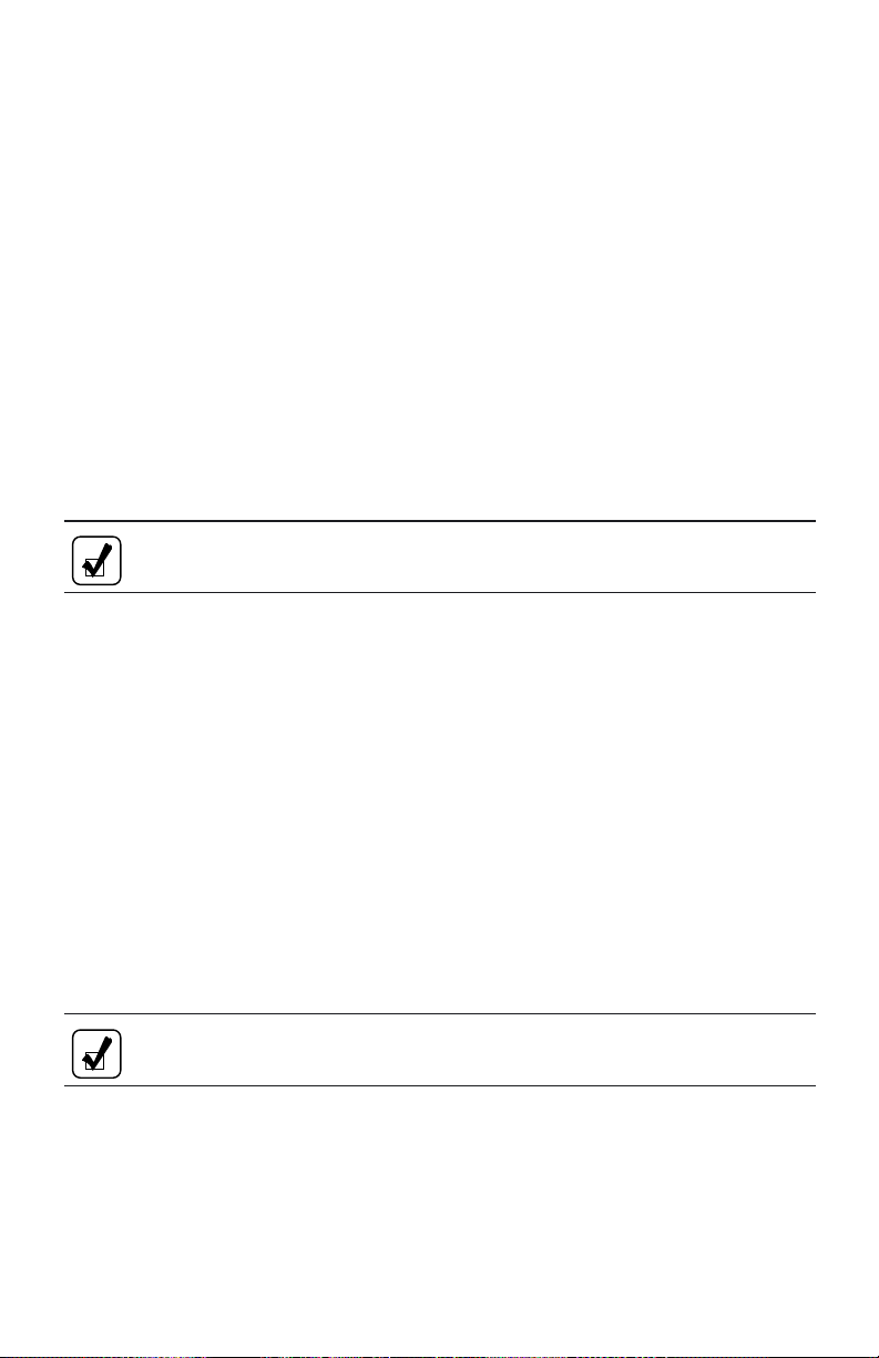
Lever Shift Selector.
To Begin the Diagnostic Process:
1. Bring the vehicle to a stop at a safe location.
2. Apply the parking brake.
To Display Stored Codes:
1. Press the DISPLAY MODE/DIAGNOSTIC button once to access the
diagnostic display mode—press the button twice if a transmission oil level
sensor is installed.
2. Observe the digital display for codes.
— Diagnostic codes will appear one digit at a time on WTEC III
pushbutton or lever shift selectors.
— Diagnostic codes will appear two characters at a time on Allison 4
Generation Controls pushbutton or lever shift selectors.
3. Press the MODE button to see the next code—repeat for subsequent codes.
NOTE: Be sure to record all codes displayed before they are cleared.
This is essential for troubleshooting.
To Clear Active Indicators and Inactive Codes then Resume Vehicle Operation:
1. Clear active indicators and inactive codes.
— WTEC III Controls—To clear active indicators such as the CHECK
TRANS light, press and hold the MODE button for approximately
three seconds until the MODE INDICATOR (LED) flashes. Release
the MODE button and active indicators will not be illuminated. To
clear inactive codes, press and hold the MODE button for 10 seconds.
Some codes are self-clearing and others require ignition cycles to clear.
— Allison 4
th
Generation Electric Controls—Press and hold the
MODE button for 10 seconds to clear both active indicators and
inactive codes.
2. Begin operating as normal—have the transmission checked at the earliest
opportunity by an Allison Transmission distributor or dealer.
th
NOTE: If the condition that caused the code is still present, the code
will again become active.
64
Page 66

DIAGNOSTIC CODE LISTINGS AND PROCEDURES (WTEC III CONTROLS)
The following table presents information about the diagnostic codes which may
occur during the operation of the transmission. For additional information, refer to
TS2973EN Troubleshooting Manual for WTEC III Controls.
Code Listings And Procedures (WTEC III Controls)
CODES QUICK CHECKS
MAIN
CODE
13 12 Check:
ECU Input Voltage
Low
13 13
ECU Input Voltage
Medium Low
13 23
ECU Input Voltage
High
14 12, 23 Check:
Oil Level Sensor
21 12, 23 Check:
Throttle Position
Sensor
SUB
CODE
a. Battery direct ground and power connections are
tight and clean.
b. Vehicle batteries are charged.
c. Vehicle charging system is not over- or
under-charging.
d. VIM fuse is good.
e. VIM connections are tight, clean, and undamaged.
f. Vehicle manufacturer supplied wiring is correct.
g. ECU connectors are tight, clean, and undamaged.
a. Is transmission equipped with oil level sensor?
b. Engine speed sensor, output speed sensor,
temperature sensor, and oil level sensor are
working correctly.
c. Wiring harness has no opens, shorts-to-ground, or
shorts-to-battery.
a. TPS connector is properly connected.
b. End of TPS cable is pulled out properly.
c. Engine fuel lever is in idle position.
d. Engine fuel lever provides proper amount of
stroke on TPS cable.
e. Wiring harness to TPS has no opens,
shorts-between-wires, or shorts-to-ground.
f. TPS for proper operation and resistance readings.
65
Page 67

Code Listings And Procedures (WTEC III Controls)
CODES QUICK CHECKS
MAIN
CODE
SUB
CODE
22 14, 15, 16 Check:
a. Speed sensors and connectors are tight, clean, and
Speed Sensors
undamaged.
b. Wiring harness to sensors has no opens,
shorts-between-wires, or shorts-to-ground.
23 12, 13, 14,
15, 16
Check:
a. ECU connectors are tight, clean, and undamaged.
b. Shift selector connector is tight, clean, and
undamaged.
Shift Selectors
c. Wiring harness has no opens, shorts-between-
wires, or shorts-to-ground.
d. Shift selector(s) for proper operation.
24 12 Check:
a. Air temperature is below –32°C (–25°F)
• If yes, this is a correct response for
Sump Fluid
Temperature Cold
temperature.
• If no, check that main transmission connector is
tight, clean, and undamaged.
b. ECU connectors are tight, clean, and undamaged.
24 23 Verify the overheat situation. Check:
a. Correct dipstick is installed.
b. Fluid level is correct. Refer to CARE AND
MAINTENANCE section.
Sump Fluid
Temperature Hot
• If fluid level is incorrect—correct fluid level.
• If fluid level is correct—check for cause of
overheating.
c. Check if ECU and transmission connectors are
tight, clean, and undamaged.
25 00, 11, 22,
33, 44, 55,
66, 77
Check:
a. Speed sensor connector is tight, clean, and
undamaged.
b. ECU connectors are tight, clean, and undamaged.
Output Speed
Sensor
c. Fluid level is correct. Refer to CARE AND
MAINTENANCE section.
d. Wiring harness to sensor has no opens,
shorts-between-wires, or shorts-to-ground.
(cont’d)
66
Page 68

Code Listings And Procedures (WTEC III Controls)
CODES QUICK CHECKS
MAIN
CODE
SUB
CODE
26 00, 11 Check:
a. TPS for proper operation, related harness for
Throttle/Engine
Coolant Source Not
Detected
opens and shorts.
b. Serial connection to engine is tight, clean, and
undamaged.
c. SCI wiring harness has no opens or shorts.
32 00, 33, 55,77Check:
a. Correct dipstick is installed.
b. Fluid level is correct. Refer to CARE AND
MAINTENANCE section.
C3 Pressure Switch
Open
c. Main transmission connector is tight, clean, and
undamaged.
d. ECU connectors are tight, clean, and undamaged.
e. Wiring harness has no opens, shorts-between-
wires, or shorts-to-ground.
33 12, 23 Check:
a. Main transmission connector is tight, clean, and
Sump Oil
Temperature Sensor
Failure
undamaged.
b. ECU connectors are tight, clean, and undamaged.
c. Wiring harness has no opens, shorts-between-
wires, or shorts-to-ground.
34 12, 13, 14,
15, 16, 17
a. Recalibrate ECU, if possible.
b. Replace ECU if not possible to recalibrate.
EEPROM
35 00, 16 Check:
a. ECU connectors are tight, clean, and undamaged.
b. VIM connectors are tight, clean, and undamaged.
Power Interruption
Real Time Write
Interruption
c. Vehicle manufacturer supplied wiring has correct
power and ground connections.
d. Power connections are battery direct.
e. Ground connections are battery direct.
f. Ignition switch connections are correct.
(cont’d)
67
Page 69

Code Listings And Procedures (WTEC III Controls)
CODES QUICK CHECKS
MAIN
CODE
36 00, 01, 02
SUB
CODE
a. If able, recalibrate ECU; if not, replace ECU.
b. Check that ECU is compatible with TransID level
Hardware/Software
Not Compatible
(36 01).
c. Troubleshoot TransID wire and circuit for
short-to-battery (36 02).
42 12, 13, 14,
15, 16, 21
22, 23, 24,
26
Check:
a. Main transmission connector is tight, clean, and
undamaged.
b. ECU connectors are tight, clean, and undamaged.
c. Wiring harness is not pulled too tight, and there is
no damage, chafing, or screws through harness.
Short-to-Battery in
Solenoid Circuit
d. Wiring harness has no opens, shorts-between-
wires, or shorts-to-ground.
e. Unauthorized repairs have not been made.
f. Change harness (optional).
44 12, 13, 14,
15, 16, 21,
22, 23, 24,
26
Solenoid Circuit
Short-to-Ground
45 12, 13, 14,
15, 16, 21,
22, 23, 24,
26
Solenoid Circuit
Open
Check:
a. Main transmission connector is tight, clean, and
undamaged.
b. ECU connectors are tight, clean, and undamaged.
c. Wiring harness has no opens, shorts-between-
wires, or shorts-to-ground.
Check:
a. Main transmission connector is tight, clean, and
undamaged.
b. ECU connectors are tight, clean, and undamaged.
c. Wiring harness has no opens or shorts.
46 21, 26, 27 Check:
a. Main transmission connector is tight, clean, and
undamaged.
Solenoid
Overcurrent
b. ECU connectors are tight, clean, and undamaged.
c. Wiring harness has no opens, shorts-between-
wires, or shorts-to-ground.
d. Replace ECU.
(cont’d)
68
Page 70

Code Listings And Procedures (WTEC III Controls)
(cont’d)
CODES QUICK CHECKS
MAIN
CODE
51 01, 10, 12,
Offgoing Ratio Test
(During Shift)
52 01, 08, 32,
SUB
CODE
21, 23, 24,
35, 42, 43,
45, 46, 53,
64, 65,
XY*
34, 54, 56,
71, 72, 78,
79, 99,
XY*
Check:
a. Output and turbine speed sensor connectors are
tight, clean, and undamaged.
b. Speed sensor wiring harness has no opens,
shorts-between-wires, or shorts-to-ground.
c. Correct dipstick is installed.
d. Fluid level is correct. Refer to CARE AND
MAINTENANCE section.
Check:
a. Output and turbine speed sensor connectors are
tight, clean, and undamaged.
b. Speed sensor wiring harness has no opens,
shorts-between-wires, or shorts-to-ground.
c. Main wiring harness to transmission has no
Offgoing C3
Pressure Switch Test
(During Shift)
shorts-between-wires or shorts-to-ground.
d. Correct dipstick is installed.
e. Fluid level is correct. Refer to CARE AND
MAINTENANCE section.
53 08, 09, 18,
19, 28, 29,
38, 39, 48,
49, 58, 59,
68, 69, 78,
99, XY*
Offgoing Speed Test
(During Shift)
Check:
a. Turbine and engine speed sensor connectors are
tight, clean, and undamaged.
b. Speed sensor wiring harness has no opens,
shorts-between-wires, or shorts-to-ground.
c. Correct dipstick is installed.
d. Fluid level is correct. Refer to CARE AND
MAINTENANCE section.
*Additional codes could be logged for other shifts where X indicates range
shifted from and Y indicates range shifted to.
69
Page 71

Code Listings And Procedures (WTEC III Controls)
(cont’d)
CODES QUICK CHECKS
MAIN
CODE
54 01, 07, 10,
SUB
CODE
12, 17, 21,
23, 24, 27,
32, 34, 35,
42, 43, 45,
46, 53, 54,
56, 64, 65,
70, 71, 72,
80, 81, 82,
83, 85, 86,
87, 92, 93,
Check:
a. Turbine and output speed sensor connectors are
tight, clean, and undamaged.
b. Speed sensor wiring harness has no opens,
shorts-between-wires, or shorts-to-ground.
c. Correct dipstick is installed.
d. Fluid level is correct. Refer to CARE AND
MAINTENANCE section.
e. EEPROM calibration is correct for the
transmission.
95, 96,
XY*
Oncoming Ratio
Test (After Shift)
55 07, 17, 27,
87, 97,
XY*
Check:
a. Correct dipstick is installed.
b. Fluid level is correct. Refer to CARE AND
MAINTENANCE section.
c. Output and turbine speed sensor connectors are
tight, clean, and undamaged.
Oncoming C3
Pressure Switch Test
(After Shift)
d. Speed sensor wiring harness has no opens,
shorts-between-wires, or shorts-to-ground.
e. Transmission connector is tight, clean, and
undamaged.
f. ECU connectors are tight, clean, and undamaged.
g. C3 pressure switch wiring has no opens,
shorts-between-wires, or shorts-to-ground.
*Additional codes could be logged for other shifts where X indicates range
shifted from and Y indicates range shifted to.
70
Page 72

Code Listings And Procedures (WTEC III Controls)
CODES QUICK CHECKS
MAIN
CODE
56 00, 11, 22,
SUB
CODE
33, 44, 55,
66, 77
Check:
a. Turbine and output speed sensor connectors are
tight, clean, and undamaged.
b. Speed sensor wiring harness has no opens,
shorts-between-wires, or shorts-to-ground.
c. Transmission connector is tight, clean, and
Range Verification
Ratio Test
undamaged.
d. ECU connectors are tight, clean, and undamaged.
e. Correct dipstick is installed.
f. Fluid level is correct. Refer to CARE AND
MAINTENANCE section.
57 11, 22, 44,
66, 88, 99
Check:
a. Correct dipstick is installed.
b. Fluid level is correct. Refer to CARE AND
MAINTENANCE section.
c. Output and turbine speed sensor connectors are
tight, clean, and undamaged.
Range Verification
C3 Pressure Switch
Test
d. Speed sensor wiring harness has no opens,
shorts-between-wires, or shorts-to-ground.
e. Transmission connector is tight, clean, and
undamaged.
f. ECU connectors are tight, clean, and undamaged.
g. C3 pressure switch wiring has no opens,
shorts-between-wires, or shorts-to-ground.
61 00 Check:
a. Fluid level is correct. Refer to CARE AND
Retarder Over
Temperature
MAINTENANCE section.
b. Retarder apply system is not allowing retarder and
throttle to be applied at the same time.
c. Fluid cooler is adequately sized for load.
(cont’d)
71
Page 73

Code Listings And Procedures (WTEC III Controls)
(cont’d)
CODES QUICK CHECKS
MAIN
CODE
SUB
CODE
62 12, 23, 32,33Check:
a. Retarder temperature measured with diagnostic
tool is consistent with code; or determine if code
is active using shift selector.
b. Sensor connector is tight, clean and undamaged.
Retarder
Temperature Sensor,
Engine Coolant
Sensor
c. ECU connectors are tight, clean, and undamaged.
d. Temperature sensor circuit has no opens,
shorts-between-wires, or shorts-to-ground.
e. Serial connection to engine computer is tight,
clean, and undamaged.
f. SCI wiring harness has no opens or shorts.
63 00, 26, 40,
41, 47
Check input wiring, switches, and connectors to
determine why input states are different.
Input Function Fault
64 12, 23 Use diagnostic tool to read retarder counts and identify
Retarder Modulation
Request Device
problem wires. Check wiring for short-to-battery, ground
wire open, or short-to-ground.
Fault
66 00, 11, 22 Check: a. b. c.
a. Serial connection to engine computer is tight,
clean, and undamaged.
Serial
Communications
Interface Fault
b. SCI wiring harness has no opens, shorts, or
shorts-to-ground.
c. If diagnostic tool is not available, also be sure that
transmission ECU connections are tight, clean, and
undamaged.
d. Problem with CAN link or engine controls.
69 27, 28, 29,
33, 34, 35,
36, 39, 41,
a. Clear diagnostic code and retry vehicle start.
b. If code recurs, reprogram or replace ECU.
42, 43
ECU Malfunction
70 12, 13, 14 Reset ECU
Software Problem
72
Page 74

DIAGNOSTIC CODE LISTINGS AND PROCEDURES
(ALLISON 4
th
GENERATION CONTROLS)
The following table presents information about the diagnostic codes which may
occur during the operation of the transmission. For additional information, refer to
TS3989EN Troubleshooting Manual for Allison 4
th
Generation Controls.
Code Listings And Procedures
(Allison 4
th
CODES QUICK CHECKS
C1312, C1313
Retarder
Request
Use an Allison DOC™ diagnostic tool to read Retarder
Request Percentage. Check wiring for short-to-battery, ground
wire open, or short-to-ground.
Sensor Fault
P0122, P0123
Pedal Position
Sensor Fault
1. Check:
a. TPS connector is properly connected.
b. End of TPS cable is pulled out properly.
c. Engine fuel lever is in idle position.
d. Engine fuel lever provides proper amount of stroke
on TPS cable.
e. Wiring harness to TPS has no opens,
shorts-between-wires, or shorts-to-ground.
f. TPS for proper operation and resistance readings.
P0218
Transmission
Over
Temperature
1. Verify the overheat situation and check:
a. Correct dipstick is installed.
b. Proper fluid level. Refer to CARE AND
MAINTENANCE section.
i. If fluid level is incorrect—correct the fluid
level.
ii. If fluid level is correct—check for the cause of
overheating.
2. Check that the TCM and transmission connectors are
tight, clean, and undamaged.
P0602
TCM Not
1. Recalibrate the TCM. If unable to recalibrate, replace
the TCM.
Programmed
P0610
TCM Vehicle
1. Update TCM calibration to match transmission
configuration.
Options Error
Generation Controls)
73
Page 75

Code Listings And Procedures
(Allison 4
P0613
TCM
Processor
P0614
Torque
Control Data
Mismatch—
TCM/ECM
P0634
TCM Internal
temperature
too High
P063E
Auto
Configuration
Throttle Input
Not Present
th
Generation Controls)
(cont’d)
1. Contact Allison Transmission Technical Assistance
Center at: 1-800-252-5283.
1. Check:
a. Data link communication connectors at engine and
transmission controllers are tight, clean, and
undamaged.
b. Data link communications wiring harness has no
opens, shorts, or shorts-to-ground.
— The resistance between J1939 CAN high and
CAN low wires should be 60 Ohms.
c. No unauthorized engine power updates were made.
2. Update engine software to be compatible with
transmission torque requirements:
a. Add necessary engine torque control functions, or
b. Reduce engine power and torque ratings.
1. Check:
a. High temperature components such as exhaust lines
in the vicinity of the TCM.
2. Shield or relocate TCM, if appropriate.
1. Check:
a. Data link communication connectors at engine and
transmission controllers are tight, clean, and
undamaged.
b. Data link communications wiring harness has no
opens, shorts, or shorts-to-ground.
— The resistance between J1939 CAN high and
CAN low wires should be 60 Ohms
c. TPS (if installed) for proper operation, related
harness for opens and shorts.
74
Page 76

Code Listings And Procedures
(Allison 4
th
Generation Controls)
(cont’d)
P063F
Auto
Configuration
Engine
Coolant Not
Present
P0658, P0659,
P2670, P2671,
P2685, P2686
Actuator
Supply
Voltage Fault
P0701
Transmission
Control
System
Performance
P0702
Transmission
Control
System
Electrical
1. Check:
a. Data link communication connectors at engine and
transmission controllers are tight, clean, and
undamaged.
b. Data link communications wiring harness has no
opens, shorts, or shorts-to-ground.
— The resistance between J1939 CAN high and
CAN low wires should be 60 Ohms.
c. Engine coolant temp sensor harness for opens and
shorts.
1. Check:
a. Main transmission connector is tight, clean, and
undamaged.
b. TCM connector is tight, clean, and undamaged.
c. Wiring harness has no opens, shorts-between-wires,
or shorts-to-ground.
1. Let the vehicle idle with parking brake applied, wheels
chocked, and vehicle level. Check:
a. Correct dipstick installed.
b. Correct fluid level.
2. Check:
a. Main transmission connector is tight, clean, and
undamaged.
b. TCM connector is tight, clean, and undamaged.
c. Wiring harness has no opens, shorts-between-wires,
or shorts-to-ground.
1. Check:
a. Main transmission connector is tight, clean, and
undamaged.
b. TCM connector is tight, clean, and undamaged.
c. Wiring harness has no opens, shorts-between-wires,
or shorts-to-ground.
75
Page 77

Code Listings And Procedures
th
(Allison 4
Generation Controls)
(cont’d)
P0703
Brake Switch
Circuit
P0708
Transmission
Range Sensor
Circuit
P070C, P070D
Transmission
Fluid Level
Sensor Fault
P0711, P0712,
P0713
Transmission
Fluid
Temperature
Circuit Fault
P0716, P0717,
P0721, P0722,
P0726, P0727
Speed Sensor
Circuit Fault
P0719
Brake Switch
ABS Input
Circuit Fault
1. Check:
a. Brake pressure switch, wiring, and connectors to
determine why brake input is not being sent to the
TCM.
1. Check:
a. TCM connector is tight, clean, and undamaged.
b. Strip-type shift selector connector is tight, clean,
and undamaged.
c. Wiring harness has no opens, shorts-between-wires,
or shorts-to-ground.
2. Strip-type shift selector for proper operation.
1. Check:
a. Is the transmission equipped with an oil level
sensor?
b. Engine speed sensor, output speed sensor,
temperature sensor, and oil level sensor working
correctly.
c. Wiring harness has no opens, shorts-between-wires,
or shorts-to-ground.
1. Check:
a. Correct fluid level.
b. Main transmission connector is tight, clean, and
undamaged.
c. TCM connector is tight, clean, and undamaged.
d. Wiring harness has no opens, shorts-between-wires,
or shorts-to-ground.
1. Check:
a. Speed sensors and connectors are tight, clean, and
undamaged.
b. Wiring harness has no opens, shorts-between-wires,
or shorts-to-ground.
1. Check input wiring, switches, and connectors to
determine why ABS input is not being sent to the
TCM.
76
Page 78

Code Listings And Procedures
(Allison 4
P071A
RELS Input
Fault
P071D
General
Purpose Input
Fault
P0729, P0731,
P0732, P0733,
P0734, P0735,
P0736
Incorrect Gear
Ratio
P0741
Torque
Converter
Clutch System
Stuck OFF
th
Generation Controls)
(cont’d)
1. Check brake pressure switch, wiring, and connectors to
determine why RELS input is not being sent to the
TCM.
1. Check input wiring, switches, and connectors to
determine why input states are different.
1. Check:
a. Turbine and output speed sensor connectors are
tight, clean, and undamaged.
b. Speed sensor wiring harness has no opens,
shorts-between-wires, or shorts-to-ground.
c. Wiring harness has no opens, shorts-between-wires,
or shorts-to-ground.
2. Let vehicle idle with parking brake applied, wheels
chocked, and vehicle level. Check:
a. Correct dipstick is installed.
b. Fluid level is correct.
3. TCM calibration is correct for transmission model.
1. Check:
a. Engine and turbine speed sensor connectors are
tight, clean, and undamaged.
b. Speed sensor wiring harness has no opens,
shorts-between-wires, or shorts-to-ground.
c. Wiring harness has no opens, shorts-between-wires,
or shorts-to-ground.
2. Let vehicle idle with parking brake applied, wheels
chocked, and vehicle level. Check:
a. Correct dipstick is installed.
b. Fluid level is correct.
77
Page 79

Code Listings And Procedures
th
(Allison 4
Generation Controls)
(cont’d)
P0776, P0796,
P2714, P2723
Pressure
Control
Solenoid
Controlled
Clutch Stuck
OFF
P0777, P0797,
P2715, P2724
Pressure
Control
Solenoid
Controlled
Clutch Stuck
ON
P0842, P0843
Transmission
Pressure
Switch
Solenoid 1
Circuit Fault
1. Check:
a. Turbine and output speed sensor connectors are
tight, clean, and undamaged.
b. Speed sensor wiring harness has no opens,
shorts-between-wires, or shorts-to-ground.
2. Let vehicle idle with parking brake applied, wheels
chocked, and vehicle level. Check:
a. Correct dipstick is installed.
b. Fluid level is correct.
1. Let the vehicle idle with the parking brake applied,
wheels chocked, and vehicle level. Check:
a. Correct dipstick is installed.
b. Fluid level is correct.
2. Check:
a. Main transmission connector is tight, clean, and
undamaged.
b. TCM connector is tight, clean, and undamaged.
c. PS1 diagnostic pressure switch has no opens,
shorts-between-wires, or shorts-to-ground.
78
Page 80

Code Listings And Procedures
(Allison 4
th
Generation Controls)
(cont’d)
P0880, P0881,
P0882, P0883
TCM Power
Input Signal
Fault
P0894
Transmission
Component
Slipping
P0960, P0964,
P0968, P2727,
P2736, P2761
Pressure
Control
Solenoid
Circuit Open
P0962, P0965,
P0970, P2720,
P2729, P2738,
P2764
Pressure
Control
Solenoid
Circuit Low
P0963, P0966,
P0971, P2721,
P2730, P2739,
P2763
Pressure
Control
Solenoid
Circuit High
1. Check:
a. Battery direct ground and power connections are
tight and clean.
b. Vehicle batteries are charged.
c. Vehicle charging system is not over- or
under-charging.
d. VIM fuse is good.
e. VIM connections are tight, clean, and undamaged.
f. Vehicle manufacturer supplied wiring is correct.
g. TCM connection is tight, clean, and undamaged.
1. Let the vehicle idle with the parking brake applied,
wheels chocked, and vehicle level. Check:
a. Correct dipstick is installed.
b. Fluid level is correct.
1. Check:
a. Main transmission connector is tight, clean, and
undamaged.
b. TCM connector is tight, clean, and undamaged.
c. Wiring harness has no opens.
1. Check:
a. Main transmission connector is tight, clean, and
undamaged.
b. TCM connector is tight, clean, and undamaged.
c. Wiring harness has no shorts-between-wires or
shorts-to-ground.
1. Check:
a. Main transmission connector is tight, clean, and
undamaged.
b. TCM connector is tight, clean, and undamaged.
c. Wiring harness has no shorts-between-wires.
79
Page 81

Code Listings And Procedures
th
(Allison 4
Generation Controls)
(cont’d)
P0973, P0976
Shift Solenoid
Circuit Low
P0974, P0977
Shift Solenoid
Circuit High
P0975
Shift Solenoid
Circuit Open
P0989, P0990
Retarder
Pressure
Sensor Circuit
Fault
P1891, P1892
Throttle
Position PWM
Signal Circuit
Fault
P2184, P2185
Engine
Coolant Temp
Sensor Circuit
Fault
1. Check:
a. Main transmission connector is tight, clean, and
undamaged.
b. TCM connector is tight, clean, and undamaged.
c. Wiring harness has no opens, shorts-between-wires,
or shorts-to-ground.
1. Check:
a. Main transmission connector is tight, clean, and
undamaged.
b. TCM connector is tight, clean, and undamaged.
c. Wiring harness has no shorts-between-wires.
1. Check:
a. Main transmission connector is tight, clean, and
undamaged.
b. TCM connector is tight, clean, and undamaged.
c. Wiring harness has no opens.
1. Check:
a. Retarder pressure sensor connector is tight, clean,
and undamaged.
b. TCM connector is tight, clean, and undamaged.
c. Retarder pressure circuit has no opens,
shorts-between-wires, or shorts-to-ground.
1. Check:
a. PWM throttle position sensor connector is tight,
clean, and undamaged.
b. TCM connector is tight, clean, and undamaged.
c. PWM throttle position sensor circuit has no opens,
shorts-between-wires, or shorts-to-ground.
1. Check:
a. Engine coolant temperature sensor connector is
tight, clean, and undamaged.
b. TCM connector is tight, clean, and undamaged.
c. Engine coolant temperature sensor circuit has no
opens, shorts-between-wires, or shorts-to-ground.
80
Page 82

Code Listings And Procedures
(Allison 4
th
Generation Controls)
(cont’d)
P2637, P2641
Torque
Management
Feedback
Signal Fault
P2740
Retarder Oil
Temperature
Hot
P2742, P2743
Retarder Oil
Temperature
Sensor Circuit
Fault
P278A
Kickdown
Switch Circuit
P2793
Gear Shift
Direction
Circuit
1. Check that no unauthorized engine power upgrades
were made.
2. Check that engine software is compatible with
transmission torque requirements, otherwise:
a. Recalibrate engine controller with compatible
software, or
b. Reduce engine power and torque ratings.
1. Check:
a. Transmission fluid level is correct.
b. Retarder apply system is not allowing retarder and
throttle to be applied at the same time.
c. Vehicle manufacturer’s transmission oil cooler is
adequately sized for heat load.
1. Check:
a. Retarder temperature measured with Allison DOC™
diagnostic tool is consistent with code, or determine
if code is active using the shift selector.
b. Retarder temperature sensor connector is tight,
clean, and undamaged.
c. TCM connector is tight, clean, and undamaged.
d. Temperature sensor circuit has no opens,
shorts-between-wires, or shorts-to-ground.
1. Check input wiring, switches, and connectors to
determine why kickdown input is not being sent to the
TCM.
1. Check:
a. Shift selector connector is tight, clean, and
undamaged.
b. TCM connector is tight, clean, and undamaged.
c. Gear shift direction circuit has no opens,
shorts-between-wires, or shorts-to-ground.
81
Page 83

Code Listings And Procedures
th
(Allison 4
Generation Controls)
(cont’d)
U0001
High Speed
CAN Bus
Reset Counter
Overrun
U0010
CAN Bus
Reset Counter
Overrun
U0100
Lost
Communications with
ECM/PCM
(J1587)
U0103, U0291
Lost
Communications with
Gear Shift
Module (Shift
Selector)
U0115
Lost
Communications with
ECM/PCM
(J1939)
1. Check:
a. High speed CAN connectors at engine and
transmission controllers are tight, clean, and
undamaged.
b. High speed CAN wiring harness has no opens,
shorts-between-wires, or shorts-to-ground.
— The resistance between the CAN high and
CAN low wires should be 60 Ohms.
1. Check:
a. J1939 CAN connectors at engine and transmission
controllers are tight, clean, and undamaged.
b. J1939 CAN wiring harness has no opens,
shorts-between-wires, or shorts-to-ground.
— The resistance between the CAN high and
CAN low wires should be 60 Ohms.
1. Check:
a. Serial communications interface connections at
engine are tight, clean, and undamaged.
b. TCM connector is tight, clean, and undamaged.
c. Serial communication interface wiring harness has
no opens, shorts-between-wires, or shorts-to-ground.
1. Check:
a. Shift selector connector is tight, clean, and
undamaged.
b. TCM connector is tight, clean, and undamaged.
c. Shift selector wiring harness has no opens,
shorts-between-wires, or shorts-to-ground.
1. Check:
a. J1939 CAN connectors at engine and transmission
controllers are tight, clean, and undamaged.
b. J1939 CAN wiring harness has no opens,
shorts-between-wires, or shorts-to-ground.
— The resistance between the CAN high and
CAN low wires should be 60 Ohms.
82
Page 84

Code Listings And Procedures
(Allison 4
th
Generation Controls)
(cont’d)
U0304, U0313
Incompatible
Gear Shift
Module
U0404, U0592
Invalid Data
Received from
Gear Shift
Module
1. Check that the shift selector is an Allison supplied shift
selector.
1. Check:
a. Shift selector connector is tight, clean, and
undamaged.
b. TCM connector is tight, clean, and undamaged.
c. Shift selector wiring harness has no opens,
shorts-between-wires, or shorts-to-ground.
83
Page 85

ABBREVIATIONS AND DEFINITIONS
ABBREVIATIONS AND DEFINITIONS
ABS Anti-lock Brake System—OEM-provided means to detect and
prevent wheel stoppage to enhance vehicle handling. Retarder and
engine brakes will not apply when ABS is active.
CT Closed Throttle
DOC Diagnostic Optimized Connection
DTC Diagnostic Trouble Code
ECM Electronic Control Module—provides data to TCM/ECU.
ECU Electronic Control Unit (also commonly referred to as the
“computer” for WTEC III Controls)
EMI Electromagnetic Interference
FCC Federal Communications Commission
J1587 Engine/transmission serial data communications link.
J1939 High-speed vehicle serial data communications link.
LED Light-Emitting Diode—Electronic device used for illumination.
MH Motorhome Series.
OEM Original Equipment Manufacturer—Maker of vehicle or
equipment.
OLS Oil Level Sensor—Electronic device (optional) on control module
for indicating transmission fluid level.
84
Page 86

PC Personal Computer—Needed to run a version of Allison DOC™
diagnostic tool.
PD Powered Downshift—A downshift forced by applying brakes with
the throttle applied. Allison Transmission does not recommend
this procedure.
PDA Personal Digital Assistant—Used to run a version of Allison
DOC™ diagnostic tool.
PT Part Throttle
PTO Power Takeoff
RFI Radio Frequency Interference
ST Step Thru—A downshift forced by applying WOT, just prior to a
CT downshift.
TCM Transmission Control Module—(also commonly referred to as
the “computer” for Allison 4
th
Generation Controls)
TPS Throttle Position Sensor—Potentiometer for signaling the
position of the engine fuel control lever.
WOT Wide Open Throttle
WTEC III World Transmission Electronic Controls, Third Generation
85
Page 87

CUSTOMER SERVICE
OWNER ASSISTANCE
The satisfaction and goodwill of the owners of Allison transmissions are of
primary concern to Allison Transmission, its distributors, and their dealers.
As an owner of an Allison transmission, you have service locations throughout the
world that are eager to meet your parts and service needs with:
• Expert service by trained personnel.
• Emergency service 24 hours a day in many areas.
• Complete parts support.
• Sales teams to help determine your transmission requirements.
• Product information and literature.
Normally, any situation that arises in connection with the sale, operation, or
service of your transmission will be handled by the distributor or dealer in your
area. Check the telephone directory for the Allison Transmission service outlet
nearest you or utilize Allison Transmission’s Sales and Service Locator tool on the
Allison Transmission web site at www.allisontransmission.com. You may also
refer to Allison Transmission’s Worldwide Sales and Service Directory
(SA2229EN).
We recognize, however, that despite the best intentions of everyone concerned,
misunderstandings may occur. To further assure your complete satisfaction, we
have developed the following three-step procedure to be followed in the event a
problem has not been handled satisfactorily.
Step One—Discuss your problem with a member of management from the
distributorship or dealership. Frequently, complaints are the result of a
breakdown in communication and can quickly be resolved by a member of
management. If you have already discussed the problem with the Sales or Service
Manager, contact the General Manager. All Allison Transmission dealers are
associated with an Allison Transmission distributor. If the problem originates with
a dealer, explain the matter to a management member of the distributorship with
86
Page 88

whom the dealer has his service agreement. The dealer will provide his Allison
Transmission distributor’s name, address, and telephone number on request.
Step Two—When it appears the problem cannot be readily resolved at the
distributor level without additional assistance, contact the Allison Technical
Assistance Center at 800-252-5283. They will place you in contact with the
Regional Customer Support Manager for your area.
For prompt assistance, please have the following information available:
• Name and location of authorized distributor or dealer.
• Type and make of vehicle/equipment.
• Transmission model number, serial number, and assembly number (if
equipped with electronic controls, also provide the TCM assembly number).
• Transmission delivery date and accumulated miles and/or hours of
operation.
• Nature of problem.
• Chronological summary of your transmission’s history.
Step Three—If you are still not satisfied after contacting the Regional Customer
Support Manager, present the entire matter to the Home Office by writing to
the following address:
Allison Transmission
Manager, Warranty Administration
PO Box 894, Mail Code 462-470-PF9
Indianapolis, IN 46206-0894
The inclusion of all pertinent information will assist the Home Office in
expediting the matter.
When contacting the Home Office, please keep in mind that ultimately the
problem will likely be resolved at the distributorship or dealership using their
facilities, equipment, and personnel. Therefore, it is suggested that Step One be
followed when experiencing a problem.
Your purchase of an Allison Transmission product is greatly appreciated, and it is
our sincere desire to assure complete satisfaction.
87
Page 89

SERVICE LITERATURE
Additional service literature is available as shown in the service literature table.
This service literature provides fully illustrated instructions for the operation,
maintenance, service, overhaul, and parts support of your transmission. To be sure
that you get maximum performance and service life from your unit, you may
order publications from:
SGI, Inc.
Attn: Allison Literature Fulfillment Desk
8350 Allison Avenue
Indianapolis, IN 46268
TOLL FREE: 888-666-5799
INTERNATIONAL: 317-471-4995
Available Service Literature (WTEC III Controls)
Publication Type 3000 MH 4000 MH
Allison DOC™ For PC User Guide GN3433EN GN3433EN
Automatic Transmission Fluid
Technician’s Guide
Mechanic’s Tips* MT3004EN MT3004EN
Operator’s Manual (Motorhome
Series) *
Parts Catalog
*
Parts Catalog CD-ROM CD2150EN CD2456EN
Principles of Operation PO2454EN PO2454EN
Service Manual SM2148EN SM2457EN
Troubleshooting Manual TS2973EN TS2973EN
Worldwide Sales and Service
Directory*
* Also available on the Allison Transmission web site at
www.allisontransmission.com
GN2055EN GN2055EN
OM3349EN OM3349EN
PC2150EN PC2456EN
SA2229EN SA2229EN
88
Page 90

Available Service Literature (Allison 4thGeneration Controls)
Publication Type 3000 MH 4000 MH
Allison DOC™ For PC User Guide GN3433EN GN3433EN
Mechanic’s Tips (except 3700
MT4015EN MT4015EN
7-speed)*
Operators Manual (Motorhome
*
Series)
OM3349EN OM3349EN
Parts Catalog* PC2150EN PC2456EN
Parts Catalog on CD CD2150EN CD2456EN
Principles of Operation PO4016EN PO4016EN
Service Manual SM4013EN SM4014EN
Troubleshooting Manual TS3989EN TS3989EN
Worldwide Sales and Service
SA2229EN SA2229EN
Directory*
* Also available on the Allison Transmission web site at
www.allisontransmission.com
89
Page 91

ALLISON TRANSMISSION DISTRIBUTORS
EASTERN REGION
Atlantic Detroit Diesel-Allison, LLC
180 Route 17 South
Lodi, NJ 07644
201-489-5800
Covington Detroit Diesel-Allison
8015 Piedmont Triad Parkway
Greensboro, NC 27409
336-292-9240
Johnson & Towers, Inc.
2021 Briggs Road
Mount Laurel, NJ 08054
856-234-6990
New England Detroit Diesel-Allison, Inc.
90 Bay State Road
Wake field, MA 01880-1095
781-246-1810
CENTRAL REGION
Central Detroit Diesel-Allison, Inc.
9200 Liberty Drive
Liberty, MO 64068
816-781-8070
Clarke Power Services, Inc.
3133 East Kemper Road
Cincinnati, OH 45241
513-771-2200
Detroit Diesel-Allison Canada East
Div. of Integrated Power Systems Corp.
2997 Rue Watt
Ste. Foy, Quebec G1X 3W1
418-651-5371
Harper Detroit Diesel Ltd.
10 Diesel Drive
Toronto, Ontario M8W 2T8
416-259-3281
Penn Detroit Diesel-Allison, Inc.
8330 State Road
Philadelphia, PA 19136-2986
215-335-0500
Western Branch Diesel, Inc.
3504 Shipwright Street
Portsmouth, VA 23703
757-673-7000
W.W. Williams S.E., Inc.
2849 Moreland Avenue, S.E
Atlanta, GA 30315-0037
404-366-1070
Inland Detroit Diesel-Allison, Inc.
210 Alexandra Way
Carol Stream, IL 60188
630-871-1111
Inland Diesel, Inc.
13015 West Custer Avenue
Butler, WI 53007-0916
262-781-7100
Interstate PowerSystems, Inc.
2501 American Boulevard, East
Minneapolis, MN 55425
952-854-5511
W.W. Williams M.W., Inc.
1176 Industrial Parkway
North Brunswick, OH 44212-2342
330-225-7751
90
Page 92

SOUTHERN REGION
Caribe Detroit Diesel-Allison
Division of GT Corporation
Ceramic Ind. Park
Campo Rico Ave., Block C
Stewart & Stevenson Power, Inc.
5840 Dahlia Street
Commerce City, CO 80022
303-287-7441
Carolina, Puerto Rico 00982
787-750-5000
Detroit Diesel-Allison de Mexico S.A.
de C.V.
Av. Santa Rosa No. 58
Col. Ampliacion Norte
Tlalnepantla C.P. 54160, Estado de Mexico
Stewart & Stevenson Services, Inc.
2707 North Loop West
Houston, TX 77008
713-868-7700
525-5-5333-1800
Florida Detroit Diesel-Allison, Inc.
2277 N.W. 14th Street
Miami, FL 33125-0068
904-737-7330
United Engines, LLC
5555 West Reno Street
Oklahoma City, OK 73127
405-947-3321
WESTERN REGION
Detroit Diesel-Allison British
Columbia Ltd.
9300 - 192nd Street
Surrey, British Columbia V4N 3R8
Stewart & Stevenson
1755 Adams Avenue
San Leandro, CA 94577-1001
510-635-8991
604-888-1211
Midwest Detroit Diesel-Allison Ltd.
1460 Waverly Street
Winnipeg, Manitoba R3T OP6
204-452-8244
Pacific Detroit Diesel-Allison Company
7215 South 228th Street
Kent, WA 98032
253-854-0505
Smith Detroit Diesel-Allison, Inc.
3065 West California Avenue
Salt Lake City, UT 84104
801-415-5000
Valley Power Systems, Inc.
425 South Hacienda Boulevard
City of Industry, CA 91745-1123
626-333-1243
Waterous Power Systems
10025 - 51 Avenue
Edmonton, Alberta T6E OA8
780-437-3550
W.W. Williams S.W., Inc.
2602 S. 19th Avenue
Phoenix, AZ 85009
602-257-0561
91
Page 93

ALLISON TRANSMISSION REGIONAL OFFICES
EASTERN REGION
19 Oaklynn Drive
PO Box 400
Columbus, NJ 08022-0400
609-298-2541
CENTRAL REGION
PO Box 894, Mail Code 462-470-PF06
Indianapolis, IN 46206-0894
317-242-2327
SOUTHERN REGION
Av. Ejercito Nacional No. 843
Colonia Granada
Mexico, D.F. C.P. 11520
936-321-4248
WESTERN REGION
Suite 3510
39465 Paseo Padre Parkway
Fremont, CA 94538
510-226-8037
92
Page 94

OM3349EN 200509 www.allisontransmission.com Printed in USA 200509
 Loading...