

Page 1

3000 AND 4000 PRODUCT FAMILIES TROUBLESHOOTING MANUAL—ALLISON 4th GENERATION CONTROLS
3000 AND 4000 PRODUCT FAMILIES TROUBLESHOOTING MANUAL –
ALLISON 4TH GENERATION CONTROLS
DIAGNOSTIC TROUBLE CODES (DTC)
W elcome to the TS3989EN T roubl eshooting Manual. We make every effort to keep our service information current
and accurate. Because of the time lag involved with writing and printing processes, the transmission TCM may
report a code that has not yet been added to this document. If you encounter a code that is not yet in this
publication, please call Allison Transmission.
Go to the Table of Contents
PREFACE
Copyright © 2008 Allison Transmission, Inc.
Page 2

Page 3

2008 OCTOBER
Troubleshooting
TS3989EN
Manual
Allison Transmission
VOCATIONAL MODELS
3000 VOCATIONAL MODELS
3000 HS 3500 RDS B 300(P)(R)
3000 RDS 3500 EVS B 400(P)(R)
3000 EVS T 200
3000 MH T 300
3000 PTS
3000 TRV
3200 SP 3500 SP 3700 SP
3200 TRV
4000 VOCATIONAL MODELS
4000 EVS 4500 EVS 4700 EVS 4800 EVS B 500
4000 HS 4500 HS 4700 RDS B 500P
4000 MH 4500 RDS 4700 OFS B 500R
4000 RDS 4500 SP B 500PR
4000 TRV 4500 TRV T 425
T 450
Allison Transmission, Inc.
P.O. Box 894 Indianapolis, Indiana 46206-0894
www.allisontransmission.com
Printed in USA Copyright © 2008 Allison Transmission, Inc.
Page 4

3000 AND 4000 PRODUCT FAMILIES TROUBLESHOOTING MANUAL—ALLISON 4th GENERATION CONTROLS
FOREWORD — How to Use This Manual
This manual provides troubleshooting information for the 3000 and 4000 Product Families Transmissions. Service
Manuals SM4013EN and SM4014EN, plus Parts Catalogs PC2150EN and PC2456EN may be used in co njunction
with this manual.
This manual includes:
• Description of the 3000 and 4000 Product Families Allison 4
• Description of the electronic control system components.
• Description of diagnostic codes, system responses to faults, and troubleshooting.
• Wire, terminal, and connector repair information.
Specific instructions for using many of the available or required service tools and equipment are not included in
this manual. The service tool manufacturer will furnish instructions for using the tools or equipment.
Additional information may be published from time to time in Service Information Letters (SIL) and will be
included in future revisions of this and other manuals. Please use these SILs to obtain up-to-date information
concerning Allison Transmission products.
This publication is revised periodically to include improvements, new models, special tools, and procedures. A
revision is indicated by a new date on the title page and in the lower left corner of the rear cover. Check with your
Allison Transmission service outlet for the currently applicable publication. Additional copies of this publication
may be purchased from authorized Allison Transmission service outlets. Look in your telephone directory under
the heading of Transmissions — Truck, Tractor, etc.
TH
Generation Electronic Control system.
T ake time to review the Table of Contents and the manual. Reviewing the Table of Contents will aid you in quickly
locating information.
NOTE: Allison Transmission is providing for service of wiring harnesses and wiring harness components as
follows:
• Repair parts for the internal wiring harness and for wiring harness components attached to the
shift selector will be available through the Allison Transmission Parts Distribution Center (PDC).
Use the P/N from your appropriate parts catalog or from Appendix E in this manual. Allison
Transmission (AT) is responsible for warranty on these parts.
• Repair parts for the external harnesses and external harness components must be obtained from
St. Clair Technologies Inc. (SCTI). SCTI provides parts to any Allison customer or OEM and is
responsible for warranty on these parts. SCTI recognizes AT, manufacturers, and SCTI part
numbers. SCTI provides a technical HELPLINE at 519-627-1673 (Wallaceburg). SCTI will have
parts catalogs available. The SCTI addresses and phone numbers for parts outlets are:
St. Clair Technologies, Inc.
920 Old Glass Road
Wallaceburg, Ontario, N8A 4L8
Phone: 519-627-1673
Fax: 519-627-4227
St. Clair Technologies, Inc.
Calle Damanti S/N Col
Guadalupe—Guaymas
Sonora, Mexico 85440
Phone: 011-526-2222-43834
Fax: 011-526 2222-43553
ii Copyright © 2008 Allison Transmission, Inc.
Page 5

3000/4000 PRODUCT FAMILIES 4TH GENERATION ELECTRONIC CONTROLS TROUBLESHOOTING MANUAL
IMPORTANT SAFETY NOTICE
IT IS YOUR RESPONSIBILITY to be completely familiar with the warnings and cautions
used in this manual. These warnings and cautions advise against using specific service
procedures that can result in personal injury, equipment damage, or cause the equipment to
become unsafe. These warnings and cautions are not exhaustive. Allison Transmission could
not possibly know, evaluate, or advise the service trade of all conceivable procedures by which
service might be performed or of the possible hazardous consequences of each procedure.
Consequently, Allison Transmission has not undertaken any such broad evaluation.
Accordingly, ANYONE WHO USES A SER VICE PROCEDURE OR T OOL WHICH IS NOT
RECOMMENDED BY ALLISON TRANSMISSION MUST first be thoroughly satisfied
that neither personal safety nor equipment safety will be jeopardized by the service procedures
used.
Also, be sure to review and observe WARNINGS, CAUTIONS, and NOTES provided by the
vehicle manufacturer and/or body builder before servicing the Allison transmission in that
vehicle.
Proper service and repair is important to the safe and reliable operation of the equipment. The
service procedures recommended by Allison Transmission and described in this manual are
effective methods for performing troubleshooting operations. Some procedures require using
specially designed tools. Use special tools when and in the manner recommended.
The WARNINGS, CAUTIONS, and NOTES in this manual apply only to the Allison
transmission and not to other vehicle systems which may interact with the transmission. Be
sure to review and observe any vehicle system information provided by the vehicle
manufacturer and/or body builder at all times the Allison transmission is being serviced.
WARNINGS, CAUTIONS, AND NOTES
Three types of headings are used in this manual to attract your attention:
WARNING!
CAUTION:
NOTE: Is used when an operating procedure, practice, etc., is essential to highlight.
Is used when an operating procedure, practice, etc., which, if not correctly followed,
could result in injury or loss of life.
Is used when an operating procedure, practice, etc., which, if not strictly observed,
could result in damage to or destruction of equipment.
Copyright © 2008 Allison Transmission, Inc. iii
Page 6

3000 AND 4000 PRODUCT FAMILIES TROUBLESHOOTING MANUAL—ALLISON 4th GENERATION CONTROLS
TRADEMARKS USED IN THIS MANUAL
The following trademarks are the property of the companies indicated:
• Allison DOC
• DEXRON
®
• LPS
• Loctite
• MagiKey
• Teflon
• TranSynd
Cleaner is a registered trademark of LPS Laboratories.
TM
is a trademark of General Motors Corporation.
®
is a registered trademark of General Motors Corporation.
®
is a registered trademark of the Loctite Corporation.
®
is a registered trademark of NEXIQ Technologies, Inc.
®
is a registered trademark of the DuPont Corporation.
TM
is a trademark of Castrol Ltd.
SHIFT SELECTOR TERMS AND DISPLAY INDICATIONS
Shift selector terms and displays are represented in this manual as follows:
• Button Names — ↑, ↓, “display mode”, MODE, etc.
• Transmission Ranges — D (Drive), N (Neutral), R (Reverse), 1 (First), 2 (Second), etc.
• Displays — “o, L”; “o, K”, etc. (Display occurs one character at a time.)
iv Copyright © 2008 Allison Transmission, Inc.
Page 7

3000 AND 4000 PRODUCT FAMILIES TROUBLESHOOTING MANUAL—ALLISON 4th GENERATION CONTROLS
TABLE OF CONTENTS
Page
FOREWARD. . . . . . . . . . . . . . . . . . . . . . . . . . . . . . . . . . . . . . . . . . . . . . . . . . . . . . . . . . . . . . . . . . . . . . . . . . .ii
IMPORTANT SAFETY NOTICE . . . . . . . . . . . . . . . . . . . . . . . . . . . . . . . . . . . . . . . . . . . . . . . . . . . . . . . . . iii
WARNINGS, CAUTIONS, AND NOTES. . . . . . . . . . . . . . . . . . . . . . . . . . . . . . . . . . . . . . . . . . . . . . . . . . . iii
TRADEMARKS USED IN THIS MANUAL . . . . . . . . . . . . . . . . . . . . . . . . . . . . . . . . . . . . . . . . . . . . . . . . iv
SHIFT SELECTOR TERMS AND DISPLAY INDICATIONS. . . . . . . . . . . . . . . . . . . . . . . . . . . . . . . . . . . iv
SECTION 1. GENERAL DESCRIPTION
1–1. TRANSMISSION . . . . . . . . . . . . . . . . . . . . . . . . . . . . . . . . . . . . . . . . . . . . . . . . . . . . . . . . . . . . . . .1–1
1–2. TRANSMISSION CONTROL MODULE (TCM) . . . . . . . . . . . . . . . . . . . . . . . . . . . . . . . . . . . . . .1–3
1–3. SHIFT SELECTOR . . . . . . . . . . . . . . . . . . . . . . . . . . . . . . . . . . . . . . . . . . . . . . . . . . . . . . . . . . . . . .1–4
A. Pushbutton Shift Selector . . . . . . . . . . . . . . . . . . . . . . . . . . . . . . . . . . . . . . . . . . . . . . . . . . . . . . .1–4
B. Lever Shift Selector . . . . . . . . . . . . . . . . . . . . . . . . . . . . . . . . . . . . . . . . . . . . . . . . . . . . . . . . . . .1–5
1–4. THROTTLE POSITION SENSOR . . . . . . . . . . . . . . . . . . . . . . . . . . . . . . . . . . . . . . . . . . . . . . . . . .1–6
1–5. SPEED SENSORS. . . . . . . . . . . . . . . . . . . . . . . . . . . . . . . . . . . . . . . . . . . . . . . . . . . . . . . . . . . . . . .1–7
1–6. CONTROL MODULE. . . . . . . . . . . . . . . . . . . . . . . . . . . . . . . . . . . . . . . . . . . . . . . . . . . . . . . . . . . .1–8
1–7. WIRING HARNESSES. . . . . . . . . . . . . . . . . . . . . . . . . . . . . . . . . . . . . . . . . . . . . . . . . . . . . . . . . .1–12
A. External Wiring Harness. . . . . . . . . . . . . . . . . . . . . . . . . . . . . . . . . . . . . . . . . . . . . . . . . . . . . . .1–12
B. Internal Wiring Harness . . . . . . . . . . . . . . . . . . . . . . . . . . . . . . . . . . . . . . . . . . . . . . . . . . . . . . .1–14
1–8. VEHICLE INTERFACE MODULE . . . . . . . . . . . . . . . . . . . . . . . . . . . . . . . . . . . . . . . . . . . . . . . .1–16
1–9. AUTODETECT FEATURE. . . . . . . . . . . . . . . . . . . . . . . . . . . . . . . . . . . . . . . . . . . . . . . . . . . . . . .1–16
A. Retarder . . . . . . . . . . . . . . . . . . . . . . . . . . . . . . . . . . . . . . . . . . . . . . . . . . . . . . . . . . . . . . . . . . .1–17
B. Oil Level Sensor (OLS) . . . . . . . . . . . . . . . . . . . . . . . . . . . . . . . . . . . . . . . . . . . . . . . . . . . . . . .1–17
C. Throttle Source . . . . . . . . . . . . . . . . . . . . . . . . . . . . . . . . . . . . . . . . . . . . . . . . . . . . . . . . . . . . . .1–17
D. Engine Coolant Temperature . . . . . . . . . . . . . . . . . . . . . . . . . . . . . . . . . . . . . . . . . . . . . . . . . . .1–18
1–10. TRANSID (TID) . . . . . . . . . . . . . . . . . . . . . . . . . . . . . . . . . . . . . . . . . . . . . . . . . . . . . . . . . . . . . . .1–18
1–11. SPECIAL ELECTRONIC/ELECTRICAL TOOLS . . . . . . . . . . . . . . . . . . . . . . . . . . . . . . . . . . . .1–19
SECTION 2. DEFINITIONS AND ABBREVIATIONS
2–1. CHECK TRANS LIGHT. . . . . . . . . . . . . . . . . . . . . . . . . . . . . . . . . . . . . . . . . . . . . . . . . . . . . . . . . .2–1
2–2. ALLISON TRANSMISSION DIAGNOSTIC TOOL. . . . . . . . . . . . . . . . . . . . . . . . . . . . . . . . . . . .2–5
2–3. ABBREVIATIONS . . . . . . . . . . . . . . . . . . . . . . . . . . . . . . . . . . . . . . . . . . . . . . . . . . . . . . . . . . . . . .2–7
Copyright © 2008 Allison Transmission, Inc. v
Page 8

3000 AND 4000 PRODUCT FAMILIES TROUBLESHOOTING MANUAL—ALLISON 4th GENERATION CONTROLS
TABLE OF CONTENTS (cont’d)
Page
SECTION 3. BASIC KNOWLEDGE
3–1. BASIC KNOWLEDGE REQUIRED. . . . . . . . . . . . . . . . . . . . . . . . . . . . . . . . . . . . . . . . . . . . . . . . 3–1
3–2. USING THE TROUBLESHOOTING MANUAL. . . . . . . . . . . . . . . . . . . . . . . . . . . . . . . . . . . . . . 3–1
3–3. SYSTEM OVERVIEW . . . . . . . . . . . . . . . . . . . . . . . . . . . . . . . . . . . . . . . . . . . . . . . . . . . . . . . . . . 3–2
3–4. IMPORTANT INFORMATION IN THE TROUBLESHOOTING PROCESS. . . . . . . . . . . . . . . . 3–2
3–5. BEGINNING THE TROUBLESHOOTING PROCESS. . . . . . . . . . . . . . . . . . . . . . . . . . . . . . . . . 3–4
3–6. TCM DIAGNOSTIC PROCEDURE . . . . . . . . . . . . . . . . . . . . . . . . . . . . . . . . . . . . . . . . . . . . . . . . 3–5
3–7. RESTTING OF TCM PARAMETERS TO SUPPORT ENGINE UPDATE. . . . . . . . . . . . . . . . . . 3–6
3–8. RESETTING TCM AUTOSELECT . . . . . . . . . . . . . . . . . . . . . . . . . . . . . . . . . . . . . . . . . . . . . . . . 3–6
3–9. HYDRAULIC OPERATION DURING ELECTRICAL INTERRUPTION. . . . . . . . . . . . . . . . . . 3–6
SECTION 4. WIRE CHECK PROCEDURES
4–1. TESTING FOR OPENS, SHORTS BETWEEN WIRES, AND SHORTS-TO-GROUND. . . . . . . 4–1
4–2. TESTING AT TRANSMISSION FEEDTHROUGH CONNECTOR FOR INTERNAL
HARNESS OPENS, SHORTS BETWEEN WIRES, AND SHORTS-TO-GROUND . . . . . . . . . . 4–3
SECTION 5. FLUID CHECK PROCEDURES
5–1. OIL LEVEL SENSOR (OLS) INTRODUCTION. . . . . . . . . . . . . . . . . . . . . . . . . . . . . . . . . . . . . . 5–1
5–2. ELECTRONIC FLUID LEVEL READING (SHIFT SELECTOR) . . . . . . . . . . . . . . . . . . . . . . . . 5–3
A. Fluid Level Reading Procedure. . . . . . . . . . . . . . . . . . . . . . . . . . . . . . . . . . . . . . . . . . . . . . . . . . 5–3
5–3. ELECTRONIC FLUID LEVEL CHECK (ALLISON DOC™ FOR PC–SERVICE TOOL) . . . . . 5–5
A. Fluid Level Check Procedure . . . . . . . . . . . . . . . . . . . . . . . . . . . . . . . . . . . . . . . . . . . . . . . . . . . 5–5
5–4. COLD CHECK. . . . . . . . . . . . . . . . . . . . . . . . . . . . . . . . . . . . . . . . . . . . . . . . . . . . . . . . . . . . . . . . . 5–6
A. Purpose . . . . . . . . . . . . . . . . . . . . . . . . . . . . . . . . . . . . . . . . . . . . . . . . . . . . . . . . . . . . . . . . . . . . 5–6
B. Cold Check Procedure . . . . . . . . . . . . . . . . . . . . . . . . . . . . . . . . . . . . . . . . . . . . . . . . . . . . . . . . . 5–6
5–5 HOT CHECK . . . . . . . . . . . . . . . . . . . . . . . . . . . . . . . . . . . . . . . . . . . . . . . . . . . . . . . . . . . . . . . . . . 5–7
A. Hot Check Procedure. . . . . . . . . . . . . . . . . . . . . . . . . . . . . . . . . . . . . . . . . . . . . . . . . . . . . . . . . . 5–7
5–6 KEEPING FLUID CLEAN . . . . . . . . . . . . . . . . . . . . . . . . . . . . . . . . . . . . . . . . . . . . . . . . . . . . . . . 5–8
A. Foreign Material . . . . . . . . . . . . . . . . . . . . . . . . . . . . . . . . . . . . . . . . . . . . . . . . . . . . . . . . . . . . . 5–8
5–7 FLUID RECOMMENDATIONS . . . . . . . . . . . . . . . . . . . . . . . . . . . . . . . . . . . . . . . . . . . . . . . . . . . 5–8
vi Copyright © 2008 Allison Transmission, Inc.
Page 9

3000 AND 4000 PRODUCT FAMILIES TROUBLESHOOTING MANUAL—ALLISON 4th GENERATION CONTROLS
TABLE OF CONTENTS (cont’d)
Page
SECTION 6.DIAGNOSTIC TROUBLE CODES (DTC)
6–1. DIAGNOSTIC CODE MEMORY. . . . . . . . . . . . . . . . . . . . . . . . . . . . . . . . . . . . . . . . . . . . . . . . . . .6–1
6–2. CODE READING AND CODE CLEARING. . . . . . . . . . . . . . . . . . . . . . . . . . . . . . . . . . . . . . . . . .6–2
6–3. DIAGNOSTIC CODE RESPONSE . . . . . . . . . . . . . . . . . . . . . . . . . . . . . . . . . . . . . . . . . . . . . . . . .6–3
6–4. SHIFT SELECTOR DISPLAYS RELATED TO ACTIVE CODES . . . . . . . . . . . . . . . . . . . . . . . .6–4
6–5. DIAGNOSTIC CODE LIST AND DESCRIPTION . . . . . . . . . . . . . . . . . . . . . . . . . . . . . . . . . . . . .6–4
6–6. DIAGNOSTIC CODE TROUBLESHOOTING . . . . . . . . . . . . . . . . . . . . . . . . . . . . . . . . . . . . . . .6–14
A. Beginning the Troubleshooting Process. . . . . . . . . . . . . . . . . . . . . . . . . . . . . . . . . . . . . . . . . . .6–14
B. Solenoid Locations . . . . . . . . . . . . . . . . . . . . . . . . . . . . . . . . . . . . . . . . . . . . . . . . . . . . . . . . . . .6–14
C. Diagnostic Code Schematics . . . . . . . . . . . . . . . . . . . . . . . . . . . . . . . . . . . . . . . . . . . . . . . . . . .6–14
SECTION 7. INPUT AND OUTPUT FUNCTIONS
7–1. INPUT FUNCTIONS . . . . . . . . . . . . . . . . . . . . . . . . . . . . . . . . . . . . . . . . . . . . . . . . . . . . . . . . . . . .7–1
7–2. OUTPUT FUNCTIONS . . . . . . . . . . . . . . . . . . . . . . . . . . . . . . . . . . . . . . . . . . . . . . . . . . . . . . . . . .7–3
SECTION 8. GENERAL TROUBLESHOOTING OF PERFORMANCE COMPLAINTS
APPENDICES
A. IDENTIFICATION OF POTENTIAL CIRCUIT PROBLEMS . . . . . . . . . . . . . . . . . . . . . . . . . . . A–1
B. MEASURING CLUTCH AND RETARDER PRESSURES . . . . . . . . . . . . . . . . . . . . . . . . . . . . . B–1
C. SOLENOID AND CLUTCH CHART. . . . . . . . . . . . . . . . . . . . . . . . . . . . . . . . . . . . . . . . . . . . . . . C–1
D. WIRE/CONNECTOR CHART . . . . . . . . . . . . . . . . . . . . . . . . . . . . . . . . . . . . . . . . . . . . . . . . . . . . D–1
E. CONNECTOR PART NUMBERS, TERMINAL PART NUMBERS, . . . . . . . . . . . . . . . . . . . . . . .E–1
TOOL PART NUMBERS, AND REPAIR INSTRUCTIONS
F. THROTTLE POSITION SENSOR ADJUSTMENT . . . . . . . . . . . . . . . . . . . . . . . . . . . . . . . . . . . .F–1
G. WELDING ON VEHICLE/VEHICLE INTERFACE MODULE. . . . . . . . . . . . . . . . . . . . . . . . . . G–1
H. HYDRAULIC SCHEMATICS . . . . . . . . . . . . . . . . . . . . . . . . . . . . . . . . . . . . . . . . . . . . . . . . . . . . H–1
J. 3000 AND 4000 PRODUCT FAMILIES WIRING SCHEMATIC. . . . . . . . . . . . . . . . . . . . . . . . . . J–1
K. SOLENOID RESISTANCE CHARTS . . . . . . . . . . . . . . . . . . . . . . . . . . . . . . . . . . . . . . . . . . . . . . K–1
L. EXTERNALLY-GENERATED ELECTRONIC INTERFERENCE. . . . . . . . . . . . . . . . . . . . . . . . .L–1
M. DIAGNOSTIC TREE—3000 AND 4000 PRODUCT FAMILIES HYDRAULIC SYSTEM . . . . M–1
N. ALLISON DOC™ FOR PC–SERVICE TOOL. . . . . . . . . . . . . . . . . . . . . . . . . . . . . . . . . . . . . . . . N–1
P. INPUT/OUTPUT FUNCTIONS . . . . . . . . . . . . . . . . . . . . . . . . . . . . . . . . . . . . . . . . . . . . . . . . . . . .P–1
Q. THERMISTOR TROUBLESHOOTING INFORMATION . . . . . . . . . . . . . . . . . . . . . . . . . . . . . . Q–1
R. SAE J1939 COMMUNICATION LINK . . . . . . . . . . . . . . . . . . . . . . . . . . . . . . . . . . . . . . . . . . . . . R–1
Copyright © 2008 Allison Transmission, Inc. vii
Page 10

3000 AND 4000 PRODUCT FAMILIES TROUBLESHOOTING MANUAL—ALLISON 4th GENERATION CONTROLS
NOTES
viii Copyright © 2008 Allison Transmission, Inc.
Page 11

3000 AND 4000 PRODUCT FAMILIES TROUBLESHOOTING MANUAL—ALLISON 4th GENERATION CONTROLS
SECTION 1—GENERAL DESCRIPTION
1–1. TRANSMISSION
The Allison 4th Generation Controls feature closed-loop clutch control to provide superior shift quality over a
wide range of operating conditions. The 3000 and 4000 Product Families transmissions configurations can be
programmed to have up to six forward ranges, neutral, and one reverse range. The 3700 SP, 4700 RDS, 4700/
4800 EVS, 4700/4800 SP, and 4700 OFS have up to seven forward ranges and one reverse.
Figure 1–1 is a block diagram of the basic system inputs and outpu t s.
SHIFT SELECTOR
MODE SWITCH
SPEED SENSORS
THROTTLE POSITION SENSOR
RETARDER MODULATION
VEHICLE/ENGINE
COMMUNICATION LINKS
RANGE AND
TCM
DISPLAY
DIAGNOSTIC PRESSURE SWITCH
VIM
INPUTS OUTPUTS
Figure 1–1. Transmission Control Module
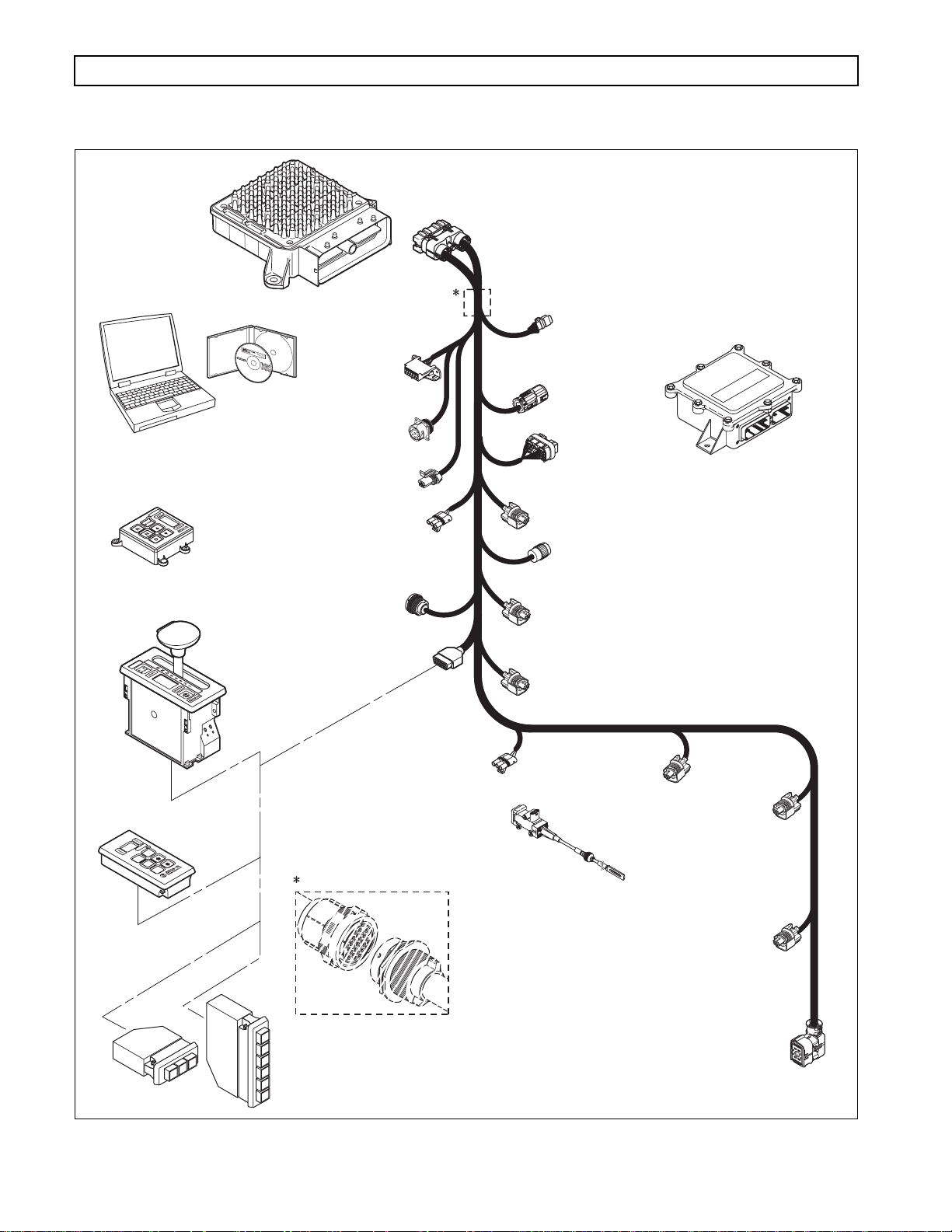
Figure 1–2 shows Allison 4th Generation electronic control components.
th
Allison 4
Generation Controls consist of the following elements:
• Remote 12V or 12/24V Max Feature Sealed Transmission Control Module (TCM)
• Remote Pushbutton or Lever Shift Selector
• Optional Secondary Shift Selector
OIL LEVEL SENSOR
SOLENOIDS
TEMPERATURE SENSOR
(SUMP/RETARDER)
FILTER LIFE
SWITCH (PS2)
V09074.00.00
NOTE:
• Throttle Position Sensor (TPS) or electronic engine throttle data or PWM signal
• Engine, Turbine, and Output Speed Sensors
• Control Module (Electro-Hydraulic Valve Body)
• Wiring Harnesses
• Vehicle Interface Module (VIM)
• Autodetect Feature
• TransID Feature
• Optional Retarder Controls
• Optional Engine Coolant Temperature Input
• Filter Life Switch (PS2)
• All external harnesses are OEM supplied.
• The VIM is an OEM option.
Copyright © 2008 Allison Transmission, Inc. 1–1
Page 12
3000 AND 4000 PRODUCT FAMILIES TROUBLESHOOTING MANUAL—ALLISON 4th GENERATION CONTROLS
GENERAL DESCRIPTION
TRANSMISSION
CONTROL
MODULE
(TCM)
ALLISON DOC™
FOR PC - SERVICE TOOL
COMPACT
PUSHBUTTON
SELECTOR
DIAGNOSTIC
TOOL
CONNECTOR
DEUTSCH 9-PIN
DIAGNOSTIC TOOL
CONNECTOR
SCI (J1587)
CONNECTOR
(OPTIONAL)
RE TARDER
MODULATION
REQUEST (RMR)
CONNECTOR
J1939
CONNECTOR
VIW
CONNECTOR
(OPTIONAL)
VIM
CONNECTOR
RE TARDER ACCUMULATOR
CONNECTOR
(3000 PRODUCT FAMILY 7-SPEED)
VEHICLE
INTERFACE
MODULE
(VIM)
ORTRANSFER CASE CONNEC T
REMOTE LEVER
SELEC TOR
REMOTE
PUSHBUTTON
SELEC TOR
R
STRIP PUSHBUTTON
SHIFT SELEC TORS
(EUROPEAN
OEM)
.
SENSOR HARNESS
CONNECTOR (OPTIONAL)
SHIFT
SELEC TOR
CONNECTOR
THROTTLE POSITION
SENSOR (TPS)
CONNECTOR
THROTTLE
MODE
N
D
POSITION
SENSOR (TPS)
OUTPUT
SPEED SENSOR
CONNECTOR
RE TARDER TEM P.
SENSOR CONNECTOR
SPEED SENSOR
CONNECTOR
(4000 PRODUCT
TURBINE
FAMI
LY)
ENGINE
SPEED
SENSOR
CONNECTOR
Bulkhead Connector (Optional)
RE TARDER “PCS5”
SOLENOID
CONNECTOR
1
2
R
N
D
3
D
NOTE: Illustration is not to scale. Actual harness
N
conguration may dier from this illustration.
R
20-WAY
TRANSMISSION
FEEDTHROUGH
HARNESS
CONNECTOR
V09274.01.00A
Figure 1–2. Typical Allison 4th Generation Control Components
1–2 Copyright © 2008 Allison Transmission, Inc.
Page 13
3000 AND 4000 PRODUCT FAMILIES TROUBLESHOOTING MANUAL—ALLISON 4th GENERATION CONTROLS
GENERAL DESCRIPTION
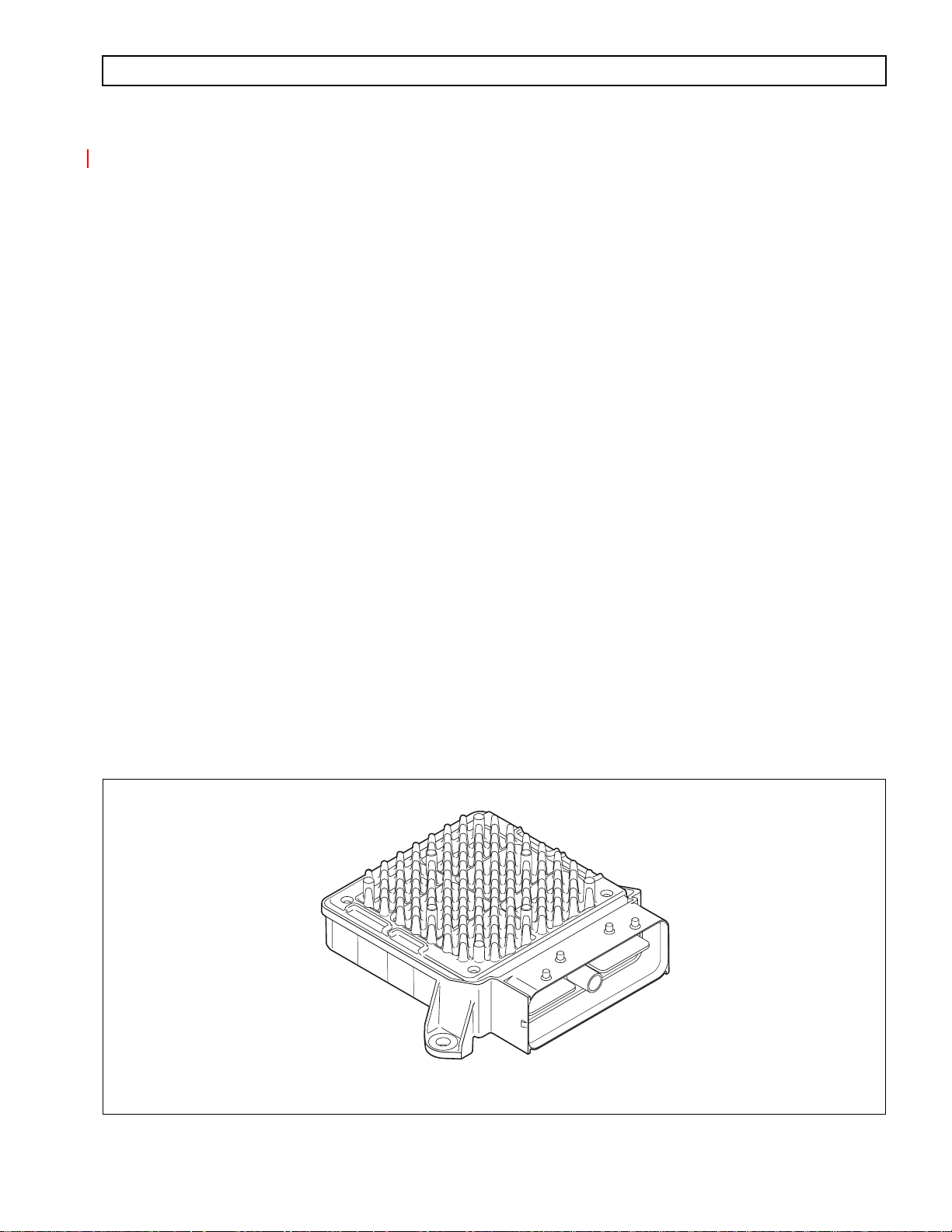
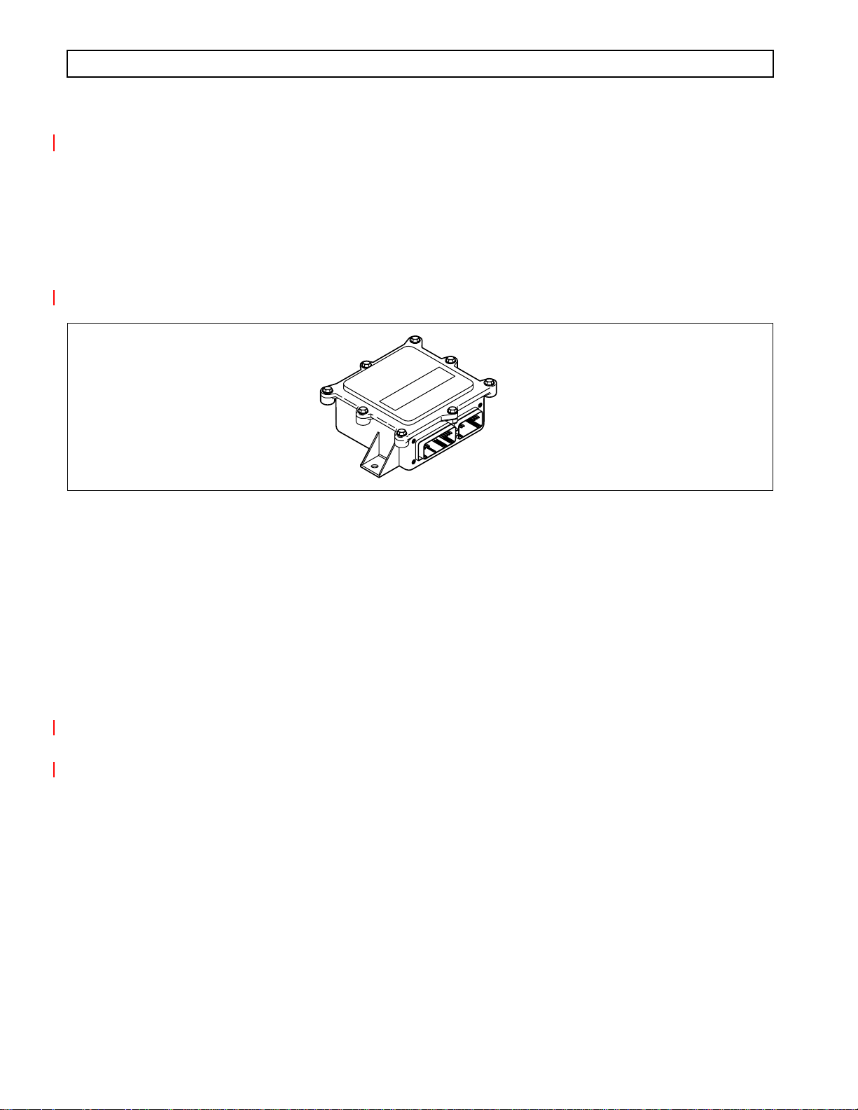
1–2. TRANSMISSION CONTROL MODULE (TCM)
The electronic control of the transmission is performed by a microcomputer. The microcomputer is an independent
controller and is referred to as a Transmission Control Module (TCM). TCMs are available in both 12V and 12/24V
configurations to match the configuration of the vehicle electrical system.
The TCM (Figure 1–3) contains the microcomputer which is the brain of the control system. The TCM receives
and processes information defining:
• Shift selector
• Throttle position
• Sump/retarder temperature
• Pressure switch state
• Engine speed
• Turbine speed
• Transmission output speed.
The TCM uses the information to:
• Control transmission solenoids
• Supply system status
• Provide diagnostic information.
Each TCM has a date code laser etched on the outer case of the TCM. This is the date when the TCM passed final
testing. This date is commonly used to denote the change configuration level of the TCM. It is normal for the TCM
date displayed electronically to be a few days prior to the date shown on the label.
V09005.00.00
Figure 1–3. Transmission Control Module (TCM)
Copyright © 2008 Allison Transmission, Inc. 1–3
Page 14

3000 AND 4000 PRODUCT FAMILIES TROUBLESHOOTING MANUAL—ALLISON 4th GENERATION CONTROLS
GENERAL DESCRIPTION
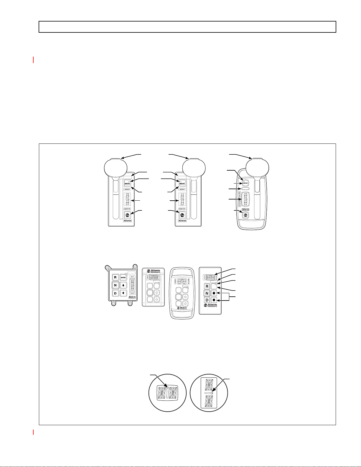
1–3. SHIFT SELECTOR
Pushbutton and lever shift selectors for the Allison 4th Generation Series are remote mounted from the TCM and
communicate to the TCM via the J1939 communications data link. All shift selectors except the strip-type
pushbutton have a dual digit vacuum fluorescent (VF) display and a mode indicator (LED). During normal
transmission operation, illumination of the LED indicator shows that a secondary or special operating condition
has been selected by pressing the MODE button. During diagnostic display mode, illumination of the LED
indicator shows that the displayed Diagnostic Trouble Code (DTC) is active. Display brightness is regulated by the
same vehicle potentiometer that controls dash light display brightness. More information on both types of shift
selectors is continued below.
A. Pushbutton Shift Selector (Figure 1–4)
There are three full-function pushbutton shift selectors and a strip pushbutton shift selector. Strip
pushbutton shift selectors are used primarily by non-North American OEMs. A full-function shift
selector has a MODE button and diagnostic display capability through the dual digit vacuum
fluorescent (VF) display. The strip pushbutton shift selector does not have a MODE button,
diagnostic capability, or adjustable illumination. The full-function pushbutton shift selector has
six (6) pushbuttons which are R (Reverse), N (Neutral), D (Drive), ↓ (Down), ↑ (Up), and MODE.
Manual forward range downshifts and upshifts are made by pressing the ↓ (Down) or ↑ (Up) arrow
buttons after selecting D (Drive). The N (Neutral) button has a raised lip to aid in finding it by touch.
The MODE button is pressed to select a secondary or special operating condition, such as
ECONOMY shift schedule. Diagnostic information is obtained by pressing the ↑ (Up) and ↓ (Down)
arrow buttons at the same time.
The strip pushbutton shift selector has either three or six range selection positions as shown in
Figure 1–4. When a strip pushbutton shift selector is used, diagnostic information must be obtained
by using the Allison DOC™ For PC–Service Tool, or a customer-supplied remote display.
1–4 Copyright © 2008 Allison Transmission, Inc.
Page 15
3000 AND 4000 PRODUCT FAMILIES TROUBLESHOOTING MANUAL—ALLISON 4th GENERATION CONTROLS
GENERAL DESCRIPTION
B. Lever Shift Selector (Figure 1–4)
The lever shift selector can have as many as six forward range positions (seven for the 7-speed
models), as well as R (Reverse) and N (Neutral). There is a hold override button which must be
pressed and held in order to move between certain selector positions. The hold override button must
be pressed when shifting between R, N, and D. The hold override button is released when the desired
selector position is reached. The selector lever can be moved freely between D and the numbered
forward ranges without pressing the hold override button. The lever selector can be chosen with the
lever on the left side or on the right side and with the R (Reverse) position toward the front or toward
the rear of the selector. Diagnostic and oil level (if sensor is present) information is obtained from the
LED display by pressing the “display mode” button.
1
2
3
4
5
D
N
R
SIX-SPEED,
LEFT-HAND
LEVER SELECTOR
HOLD OVERRIDE
BUTTON
MODE ID
MODE
INDICATOR
(LED)
MODE BUTTON
DIGITAL DISPLAY
DISPLAY MODE
DIAGNOSTIC
BUTTON
MODE
R
N
D
R
N
D
6
*
5
4
3
2
1
SEVEN-SPEED,
RIGHT-HAND
LEVER SELECTOR
MODE
R
N
D
HOLD OVERRIDE
BUTTON
MODE
INDICATOR
(LED)
MODE BUTTON
MODE ID
DIGITAL
DISPLAY
*
DISPLAY MODE
DIAGNOSTIC
BUTTON
MODE
CONTOURED
BEZEL
DIGITAL DISPLAY
MODE ID
MODE
INDICATOR (LED)
MODE BUTTON
Push simultaneously
to enter diagnostic
mode and fluid
level check
*
PUSHBUTTON SELECTORS
*NOTE:
The first number displayed in the digital display is the highest forward range available and second
number is range attained in selected position.
Visually confirm that the range selected was attained. If display is flashing, shift is inhibited.
SERVICE ICON
SERVICE ICON
Location of service icon on vertical and horizontal digital display
Figure 1–4. Typical Allison 4th Generation Shift Selectors
Copyright © 2008 Allison Transmission, Inc. 1–5
V11058.00.00
Page 16

3000 AND 4000 PRODUCT FAMILIES TROUBLESHOOTING MANUAL—ALLISON 4th GENERATION CONTROLS
GENERAL DESCRIPTION
1–4. THROTTLE POSITION SENSOR (Figure 1–5)
The Throttle Position Sensor (TPS) can be mounted to the engine, chassis, or transmission. The TPS contains a pul l
actuation cable and a potentiometer. One end of the cable is attached to the engine fuel lever and the other, inside a
protective housing, to the TPS potentiometer. Output voltage from the TPS is directed to the TCM through the
external harness. The voltage signal indicates the throttle position and, in combination with other input data,
determines shift timing.
A
Figure 1–5. Throttle Position Sensor (Without Mounting Brackets)
B
C
THROTTLE POSITION SENSOR
V00628
1–6 Copyright © 2008 Allison Transmission, Inc.
Page 17
3000 AND 4000 PRODUCT FAMILIES TROUBLESHOOTING MANUAL—ALLISON 4th GENERATION CONTROLS
GENERAL DESCRIPTION
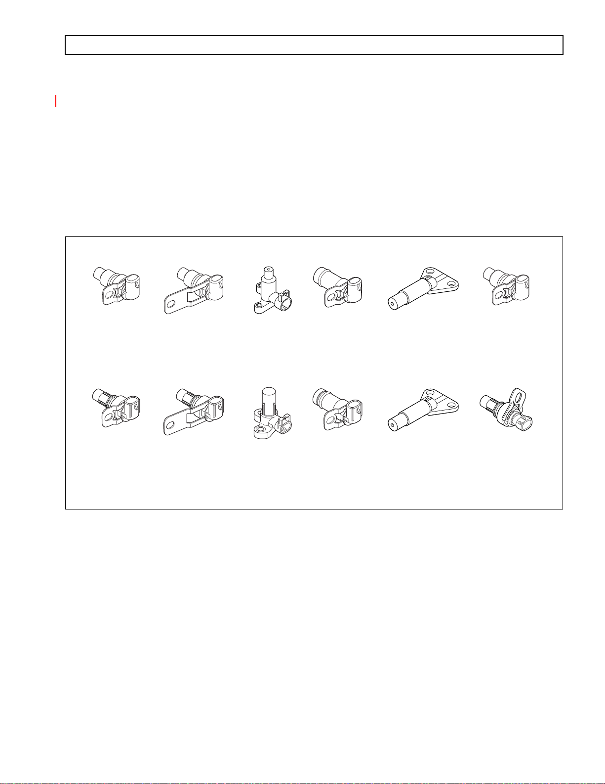
1–5. SPEED SENSORS (Figure 1–6)
Three speed sensors—engine speed, turbine speed, and output speed—provide information to the TCM. The
engine speed signal is generated by ribs on the shell of the torque converter pump. The turbine speed signal is
generated by the rotating-clutch housing spline contours. The output speed signal is generated by a toothed
member attached to the output shaft (except for the 3000 Product Family 7-speed models, where the toothed
member is the transfer case idler gear). The speed ratios between the various speed sensors allow the TCM to
determine if the transmission is in the selected range. Speed sensor information is also used to control the timing of
clutch apply pressures, resulting in the smoothest shifts possible. Hydraulic problems are detected by comparing
the speed sensor information for the current range to that range’s speed sensor information stored in the TCM
memory.
FORMER (BEFORE JANUARY, 2006)
3000 AND 4000
PRODUCT FAMILIES
ENGINE
(EXTERNAL)
3000/4000
PRODUCT FAMILIES
ENGINE
(EXTERNAL)
4000
PRODUCT FAMILY
TURBINE
(EXTERNAL)
4000
PRODUCT FAMILY
TURBINE
(EXTERNAL)
3000
PRODUCT FAMILY
TURBINE
(INTERNAL)
3000
PRODUCT FAMILY
(EXCEPT 7-SPEED)
RETARDER OUTPUT
(EXTERNAL)
CURRENT (JANUARY, 2006)
3000
PRODUCT FAMILY
TURBINE
(INTERNAL)
3000
PRODUCT FAMILY
(EXCEPT 7-SPEED)
RETARDER OUTPUT
(EXTERNAL)
Figure 1–6. Speed Sensors
3000
PRODUCT FAMILY
7-SPEED OUTPUT
(INTERNAL)
3000
PRODUCT FAMILY
7-SPEED OUTPUT
(INTERNAL)
3000 AND 4000
PRODUCT FAMILIES
OUTPUT (EXTERNAL),
4000 PRODUCT FAMILY
RETARDER
3000 AND 4000
PRODUCT FAMILIES
OUTPUT (EXTERNAL),
4000 PRODUCT FAMILY
RETARDER
V09819.00.00
Copyright © 2008 Allison Transmission, Inc. 1–7
Page 18
3000 AND 4000 PRODUCT FAMILIES TROUBLESHOOTING MANUAL—ALLISON 4th GENERATION CONTROLS
GENERAL DESCRIPTION
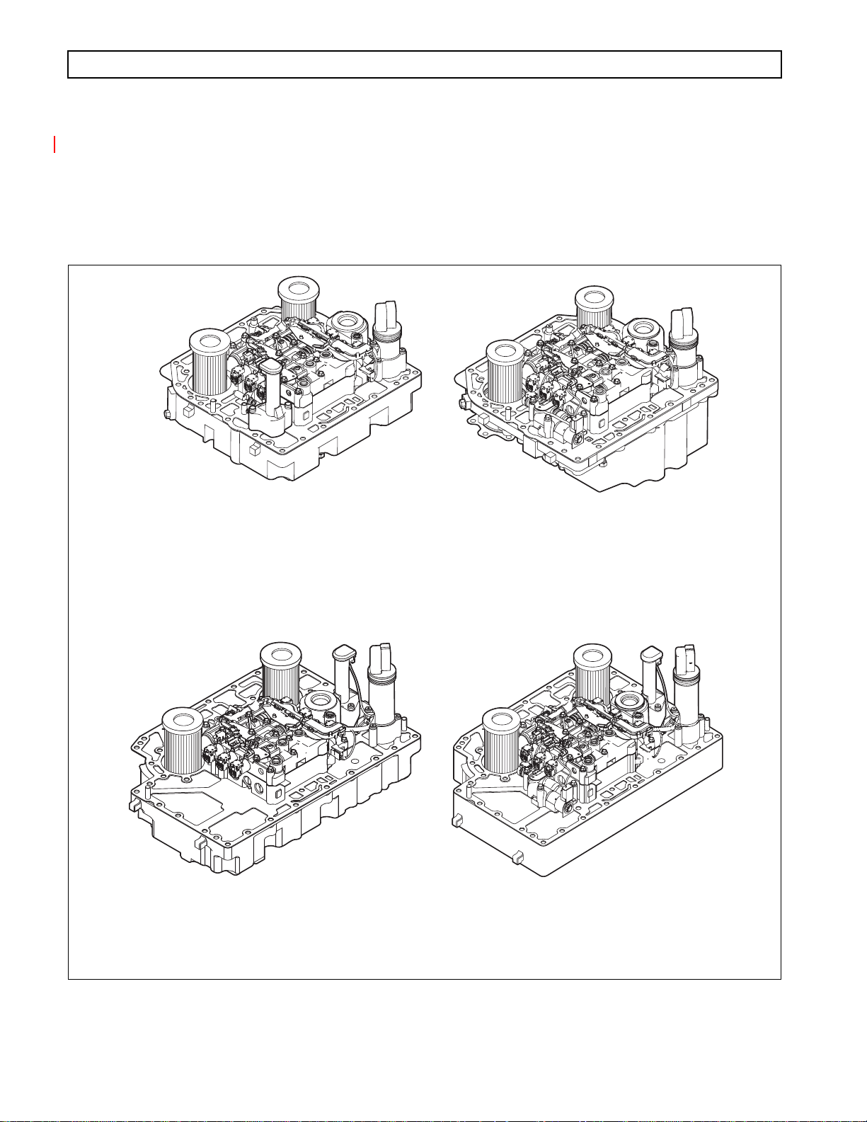
1–6. CONTROL MODULE (Figures 1–7 and 1–8)
The Allison 4
body assembly , which are mounted to an aluminum channel plate. The TCM issues commands to various solenoids
in the two valve bodies to govern fluid flow to the clutches (including torque converter clutch). The solenoids
produce an output pressure that is proportional to current from the TCM. Hence, the solenoids are referred to as
pressure control solenoids (PCS).
th
Generation Series transmission control module contains a main body assembly and solenoid valve
6-SPEED
3000 PRODUCT FAMILY
CONTROL MODULE
6-SPEED
4000 PRODUCT FAMILY
CONTROL MODULE
7-SPEED
3000 PRODUCT FAMILY
CONTROL MODULE
7-SPEED
4000 PRODUCT FAMILY
CONTROL MODULE
Figure 1–7. Allison 4th Generation Control Modules
1–8 Copyright © 2008 Allison Transmission, Inc.
V09276.00.00
Page 19
3000 AND 4000 PRODUCT FAMILIES TROUBLESHOOTING MANUAL—ALLISON 4th GENERATION CONTROLS
GENERAL DESCRIPTION
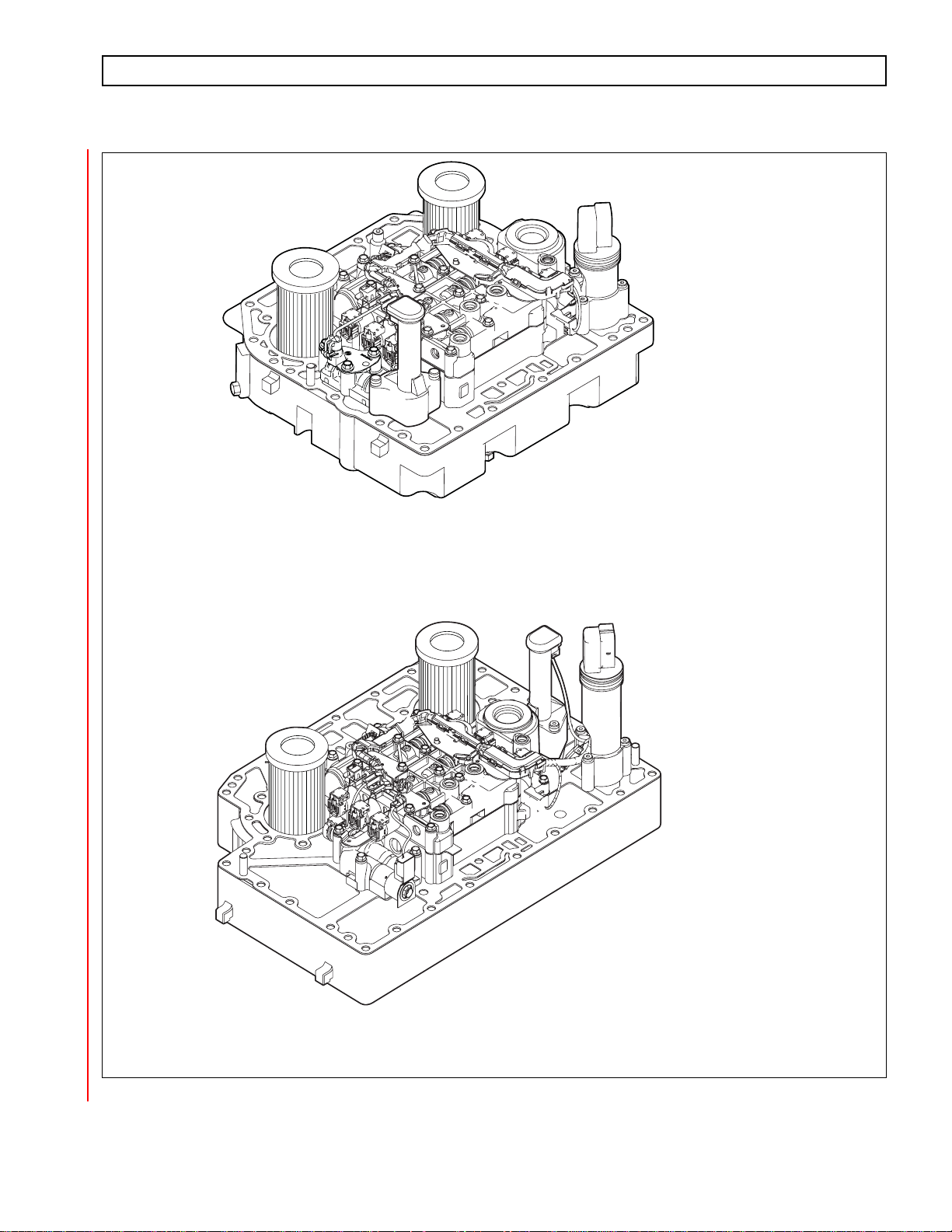
6-SPEED W/PROGNOSTICS
3000 PRODUCT FAMILY
CONTROL MODULE
6-SPEED W/PROGNOSTICS
4000 PRODUCT FAMILY
CONTROL MODULE
Figure 1–8. Allison 4th Generation Control Mudules with Prognostics
Copyright © 2008 Allison Transmission, Inc. 1–9
V09276.00.00.A
Page 20

3000 AND 4000 PRODUCT FAMILIES TROUBLESHOOTING MANUAL—ALLISON 4th GENERATION CONTROLS
GENERAL DESCRIPTION
The main valve body assembly contains the following:
• Main pressure regulator valve
• Control main regulator valve
• Converter flow valve
• Lube regulator valve
• Converter regulator valve
• Exhaust backfill valve
• Two latching logic valves
• On/Off solenoid SS1.
The solenoid valve body assembly contains the following:
• Pressure control solenoid MAIN MOD
• PCS1 (A trim)
• PCS2 (B trim)
• PCS3 (C trim)
• PCS4 (D trim)
• TCC (lockup)
• Diagnostic pressure switch PS1
• Filter Life Switch (PS2)
• Five solenoid regulator valves
• One diagnostic valve.
The low valve body assembly (in 3000 and 4000 Product Families 7-speed mod els) contains solenoid PCS6 (C6)
and one ON/OFF solenoid SS2 (C6 enable). Refer to the appropriate service manual for valve locations.
The Allison 4
in improved cooler flow and reduced pump losses when throttle position and output speed is low. The Allison 4
th
Generation controls system includes a main modulation solenoid. Modulated main pressure results
th
Generation Controls TCM commands the main mod solenoid ON when all of the following conditions are
simultaneously met:
• Sump temperature is greater than –80ºC (–112ºF) and less than 150ºC (302ºF).
• Engine speed less than 1200 rpm in all ranges except neutral. There are no restrictions on engine speed
in neutral.
• Throttle percentage less than 15 percent in reverse, low (7-speed), first, or second range. Main mod may
be commanded ON in neutral at any throttle position.
• Output speed is less than 250 rpm in neutral, reverse, low (7-speed), first, or second range.
• The PTO input to the TCM indicates the PTO is OFF.
• Shift not in progress.
The TCM may activate the main mod solenoid for improved clutch control and transmission response during other
unusual operating situations.
A temperature sensor (thermistor) is located in the internal wiring harness. Changes in sump fluid temperature are
indicated by changes in sensor resistance, which changes the signal sent to the TCM. Refer to the chart in
Appendix Q.
The oil level sensor (OLS) is a float type device mounted on the control module channel plate. The OLS senses
transmission fluid level by electronically measuring the buoyancy forces on the float. The sensor operates on
1–10 Copyright © 2008 Allison Transmission, Inc.
Page 21

3000 AND 4000 PRODUCT FAMILIES TROUBLESHOOTING MANUAL—ALLISON 4th GENERATION CONTROLS
GENERAL DESCRIPTION
5VDC supplied by the TCM. The oil level sensor is available on any 3000 and 4000 Product Families
transmissions except the 3000 7-speed transmissions.
The diagnostic pressure switch PS1 is mounted on the solenoid valve body assembly and performs the following
two functions:
• When the C5 clutch is filled, PS1 senses the PCS2 solenoid regulator valve position to verify proper C3
clutch control in reverse, neutral, and first range.
• When the C5 clutch is exhausted, as in second through sixth ranges, PS1 verifies the position of the C1
and C2 latch valves.
The turbine speed sensor is mounted on the control module for the 3000 Product Family transmissions. The turbine
speed sensor is directed at the rotating-clutch housing. The turbine speed sensor on the 4000 Product Family
transmission is located on the outside of the main housing.
A. Control System Prognostics Operation and Display
The Prognostics Package includes the following functions:
• Oil Life Monitor
• Filter Life Monitor
• Transmission Health Monitor
Use the Allison DOC™ For PC–Service Tool to review the current status of any of these functions
and a history of indicator resets. Use the Allison shift selector to review the current status of any of
these functions, provided the function being checked is in its specific display mode. See the selector
information section for that procedure.
When a specified threshold is detected for any of the prognostic functions, the SERVICE TRANS
indicator (an open-ended wrench icon located between the range select and range monitor digits in
the Allison shift selector) illuminates to alert the operator . The lamp strategy for the icon varies, either
flashing, or steady, to indicate to the operator which function detected the threshold value was
reached.
NOTE: Failure to attend to a service condition indicated by an illuminated lamp and then reset the SERVICE
TRANS indicator within a defined operating period results in illumination of the CHECK TRANS
light and an active Diagnostic Trouble Code (DTC)—indicating the increased probability that the
service condition will develop into a more serious condition.
B. Filter Life Valve Body
The Filter Life Valve Body Assembly includes the parts listed here and also shown in Figure 2.
• Filter Life Valve Body
• Filter Life Valve
• Return Spring
• Valve Stop
• Retaining Clip
• Pressure Switch 2 (Filter Life)
• M6 x 45 Long Screws (4)
This assembly cannot be retrofitted to the former channel plate assemblies. Make sure all updates
listed in this section and all other requirements are met prior to using the Prognostics features.
Copyright © 2008 Allison Transmission, Inc. 1–11
Page 22

3000 AND 4000 PRODUCT FAMILIES TROUBLESHOOTING MANUAL—ALLISON 4th GENERATION CONTROLS
GENERAL DESCRIPTION
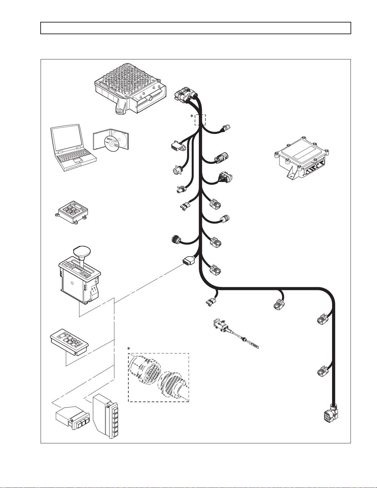
1–7. WIRING HARNESSES
A. External Wiring Harness (Figure 1–9)
The TCM uses a single 80-way connector, which is used to receive input from the following:
Transmission TPS Diagnostic tool connector
Engine Vehicle interface module (VIM) Retarder
Turbine Retarder control module Retarder temperature sensor
Output speed sensor Shift selector Accumulator
Filter life switch (PS2)
Many harnesses will include a bulkhead fitting to separate cab and chassis components. Also, many
different styles and materials for harnesses are likely to be encountered.
NOTE: Allison Transmission is providing for service of wiring harnesses and wiring harness components as
follows:
• Repair parts for the internal wiring harness and for wiring harness components attached to the
shift selector will be available through the Allison Transmission Parts Distribution Center (PDC).
Use the P/N from your appropriate parts catalog or from Appendix E in this manual. Allison
Transmission is responsible for warranty on these parts.
• Repair parts for the external harnesses and external harness components must be obtained from
St. Clair Technologies Inc. (SCTI). SCTI provides parts to any Allison customer or OEM and is
responsible for warranty on these parts. SCTI recognizes Allison Transmission, manufacturers,
and SCTI part numbers. SCTI provides a technical HELPLINE at 519-627-1673 (Wallaceburg).
SCTI will have parts catalogs available. The SCTI addresses and phone numbers for parts
outlets are:
St. Clair Technologies, Inc.
920 Old Glass Road
Wallaceburg, Ontario, Canada N8A 4L8
Phone: 519-627-1673
Fax: 519-627-4227
St. Clair Technologies, Inc.
Calle Damanti S/N Col
Guadalupe—Guaymas
Sonora, Mexico 85440
Phone: 011-526 2222-43834
Fax: 011-526-2222-43553
• SCTI is the source for external harness repair parts.
1–12 Copyright © 2008 Allison Transmission, Inc.
Page 23
3000 AND 4000 PRODUCT FAMILIES TROUBLESHOOTING MANUAL—ALLISON 4th GENERATION CONTROLS
GENERAL DESCRIPTION
TRANSMISSION
CONTROL
MODULE
(TCM)
ALLISON DOC™
FOR PC - SERVICE TOOL
COMPACT
PUSHBUTTON
SELECTOR
DIAGNOSTIC
TOOL
CONNECTOR
DEUTSCH 9-PIN
DIAGNOSTIC TOOL
CONNECTOR
SCI (J1587)
CONNECTOR
(OPTIONAL)
RE TARDER
MODULATION
REQUEST (RMR)
CONNECTOR
J1939
CONNECTOR
VIW
CONNECTOR
(OPTIONAL)
VIM
CONNECTOR
RE TARDER ACCUMULATOR
CONNECTOR
(3000 PRODUCT FAMILY 7-SPEED)
VEHICLE
INTERFACE
MODULE
(VIM)
ORTRANSFER CASE CONNEC T
REMOTE LEVER
SELEC TOR
REMOTE
PUSHBUTTON
SELEC TOR
MODE
R
N
D
STRIP PUSHBUTTON
SHIFT SELEC TORS
(EUROPEAN
OEM)
N
D
SENSOR HARNESS
CONNECTOR (OPTIONAL)
SELEC TOR
CONNECTOR
SHIFT
THROTTLE POSITION
SENSOR (TPS)
CONNECTOR
THROTTLE
POSITION
SENSOR (TPS)
OUTPUT
SPEED SENSOR
CONNECTOR
RE TARDER TEM P.
SENSOR CONNECTOR
SPEED SENSOR
CONNECTOR
(4000 PRODUCT
TURBINE
FAMI
LY)
ENGINE
SPEED
SENSOR
CONNECTOR
Bulkhead Connector (Optional)
RE TARDER “PCS5”
SOLENOID
CONNECTOR
1
2
R
3
D
NOTE: Illustration is not to scale. Actual harness
N
conguration may dier from this illustration.
R
20-WAY
TRANSMISSION
FEEDTHROUGH
HARNESS
CONNECTOR
V09274.01.00A
Figure 1–9. Typical 4th Generation Electronic Controls External Wiring Harnesses
Copyright © 2008 Allison Transmission, Inc. 1–13
Page 24
3000 AND 4000 PRODUCT FAMILIES TROUBLESHOOTING MANUAL—ALLISON 4th GENERATION CONTROLS
GENERAL DESCRIPTION
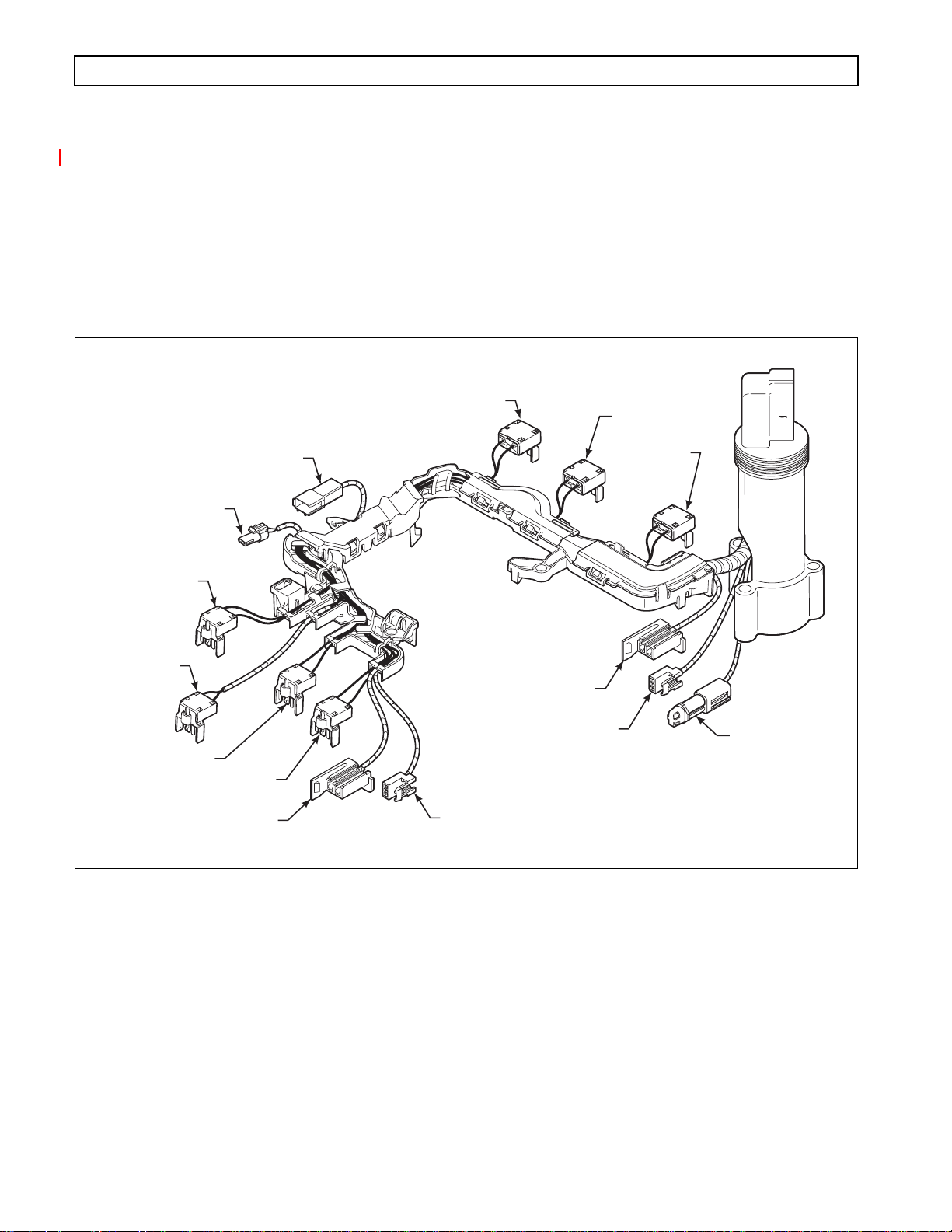
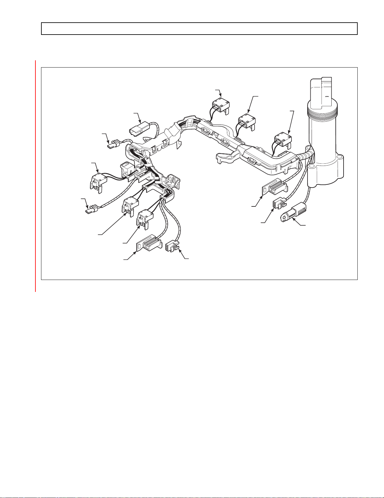
B. Internal Wiring Harness (Figure 1–10)
The internal wiring harness provides connection between the following:
• External harness
• Pressure control and shift solenoids
• Oil level sensor
• Diagnostic pressure switch
• Temperature sensor
• Turbine speed sensor.
PS1 DIAGNOSTIC
PRESSURE SWITCH
NT1 TURBINE
SPEED SENSOR
(3000 ONLY)
MAIN MOD
PCS6
(C6, 7-SPEED)
PCS4 (C4)
PCS3 (C3\C5)
(3000 AND 4000 PRODUCT
FAMILIES 7-SPEED C6 ENABLE)
SS2
TCC (LOCKUP)
OIL LEVEL SENSOR
OIL LEVEL SENSOR
(3000, EXCEPT 7-SPEED)
SS1
ON/OFF
(4000 ONLY)
PCS1 (C1)
PCS2 (C2/C3)
OIL
TEMPERATURE
SENSOR
V09251.00.00
Figure 1–10. Allison 4th Generation Internal Wiring Harness
1–14 Copyright © 2008 Allison Transmission, Inc.
Page 25
3000 AND 4000 PRODUCT FAMILIES TROUBLESHOOTING MANUAL—ALLISON 4th GENERATION CONTROLS
GENERAL DESCRIPTION
PS1 DIAGNOSTIC
PRESSURE SWITCH
NT1 TURBINE
SPEED SENSOR
(3000 ONLY)
MAIN MOD
PS2
FILTER LIFE
PCS4 (C4)
PCS3 (C3\C5)
SS2
(3000 AND 4000 PRODUCT
FAMILIES 7-SPEED C6 ENABLE)
TCC (LOCKUP)
OIL LEVEL SENSOR
OIL LEVEL SENSOR
(3000, EXCEPT 7-SPEED)
SS1
ON/OFF
(4000 ONLY)
PCS1 (C1)
PCS2 (C2/C3)
OIL
TEMPERATURE
SENSOR
V09251.00.00.A
Figure 1–11. Allison 4th Generation Inter nal Wiring Harness with Prognostics
Copyright © 2008 Allison Transmission, Inc. 1–15
Page 26
3000 AND 4000 PRODUCT FAMILIES TROUBLESHOOTING MANUAL—ALLISON 4th GENERATION CONTROLS
GENERAL DESCRIPTION
1–8. VEHICLE INTERFACE MODULE (Figure 1–12)
The vehicle interface module (VIM) provides relays, fuses, and connection points for interface with the output side
of the vehicle electrical system. VIMs are available for both 12V and 24V electrical systems. The VIM for 12V
systems uses all 12V relays. The VIM for 24V systems has all 24V relays. Refer to the appropriate parts catalog for
the transmission assembly number that you are servicing for detailed parts information. Refer to Pages D–15 and
D–16 for VIM wire number and terminal information.
Some OEMs may provide their own equivalent for the VIM which performs the same functions as the VIM shown
in Figure 1–12.
V00631.02
Figure 1–12. Vehicle Interface Module (VIM)
1–9. AUTODETECT FEATURE
Autodetect is active on the first 25 engine starts and, in the case of throttle source detection logic, may continue
past 25 ignition cycles until a valid source is determined (details follow in A through D below). Autodetect takes
place within the first 30 seconds of each engine start monitored. Autodetect searches for the presence of the
following transmission components or data inputs in the priority listed:
Retarder Present, Not Present
Oil Lever Sensor (OLS) Present, Not Present
Throttle TPS, J1587, J1939 *
Engine Coolant Temperature Sensor, J1939, J1587
* No Throttle Autodetect with MY09
Even after autodetect has been completed, it can be reset to monitor an additional group of engine starts. Reset may
be necessary if a device known to be present is not detected or if an autodetectable component or sensor was added
after the initial vehicle build. Reset is accomplished by using Allison DOC™ For PC–Service Tool. To use the
Allison DOC™ For PC–Service Tool, select “RESET AUTODETECT” to search for all four devices. Select
“RESET AUTODETECT RETARDER” to search for a retarder only. Selecting “RESET ADAPTIVE SHIFT
PARAMETERS” will not reset autodetect logic.
The Allison DOC™ For PC–Service Tool can also be used to override autodetect and manually enter the
component or sensor to be recognized by the TCM by changing appropriate “customer modifiable constants”
(CMC). The four items above are the only CMCs that are autodetectable. Other CMCs can be changed at any time
TM
and are not related to autodetect. Consult the Allison DOC
related to Allison 4
th
Generation Controls CMC. Additional details for each of the four autodetectable features are
User’s Guide, GN3433EN, for, detailed instructions
given below.
1–16 Copyright © 2008 Allison Transmission, Inc.
Page 27

3000 AND 4000 PRODUCT FAMILIES TROUBLESHOOTING MANUAL—ALLISON 4th GENERATION CONTROLS
GENERAL DESCRIPTION
A. Retarder
Autodetect searches for the presence of pressure control solenoid 5 (PCS5) to the retarder during the
first 35 engine ignition cycles. Retarder autodetect will countdown for a maximum of 35 ignition
cycles while recording detections of a retarder. A retarder will be identified as present and the ret arder
autodetect logic will stop once it is detected for three consecutive ignition cycles. If the ignition cycle
counter completes the 35 cycles before there are three consecutive detections of a retarder, the
software will log that there is no retarder and the retarder autodetect logic will stop. If the autodetect
logic is not satisfied during the first 35 engine starts, the retarder is not detected and will not function
on subsequent engine starts.
If a retarder is present but is not detected by autodetect, the retarder will not
WARNING:
function. Be sure to determine that the retarder is functioning properly
immediately after the 35
PCS5 solenoid for an open, short-to-ground, or short-to-battery condition. Use
the Allison DOC™ For PC–Service Tool to reset retarder autodetect or to
manually select the presence of the retarder after the PCS5 circuit is repaired.
th
engine start. If the retarder is not functioning, test
B. Oil Level Sensor (OLS)
NOTE: If an OLS is known to be present but has not been detected, a possible cause is that the transmission
fluid level is too low. Determine the fluid level before beginning the OLS troubleshooting.
Oil level sensor autodetect will countdown for a maximum of 25 engine starts while recording
detections of an OLS. The TCM monitors the OLS input voltage on wire 116. OLS input voltage
must exceed a predetermined level for the TCM to record a detection. Additionally, OLS detection
must occur within 12.5 seconds on any given engine start. An OLS will be identified as present and
the OLS autodetect logic will stop once it is detected during any single engine start.
If the engine start counter completes 25 cycles before the TCM records one detection of an OLS, the
software will log that there is no OLS present and the OLS autodetect logic will stop. Then the TCM
concludes that no OLS is present.
No OLS diagnostics take place until the OLS is detected. Frequently test for the presence of oil level
diagnostics if the transmission is known to contain an OLS. If an OLS is known to be present, but has
not been detected, troubleshooting the OLS circuit is required. After the OLS circuit is repaired, reset
autodetect or manually select the OLS function using the Allison DOC™ For PC–Service Tool.
C. Throttle Source
Throttle autodetect will increment a counter for a throttle source on each engine start during which
the possible throttle source is detected. When the counter for any of the sources indicates five
consecutive detections, the software will set a “confidence flag” to indicate that this is an available
throttle source. Multiple throttle sources can be detected on a single engine start and multiple
confidence flags can be set. There is no limit to the number of engine starts for autodetection of the
throttle source until a confidence flag is set for a source. Once a confidence flag is set for any one of
the sources, a counter begins to countdown for 15 additional engine starts. During the entire
autodetect period, the software will use the highest priority source as the throttle source if multiple
sources are detected before any confidence flags are set. Once a confidence flag is set, that source is
used as the source for the throttle signal. When the countdown period is complete, the software will
use the highest priority throttle source having a confidence flag set and the autodetect logic will stop.
Copyright © 2008 Allison Transmission, Inc. 1–17
Page 28

3000 AND 4000 PRODUCT FAMILIES TROUBLESHOOTING MANUAL—ALLISON 4th GENERATION CONTROLS
GENERAL DESCRIPTION
D. Engine Coolant Temperature
Engine coolant temperature sensor autodetect will countdown for a total of 25 engine starts while
recording detections of engine coolant temperature sources. A “confidence flag” will be set once a
source is detected for five consecutive engine starts. Multiple sources detected before a confidence
flag is set or multiple confidence flags will result in the highest priority source being used as the
engine coolant temperature source. Multiple sources can be detected on a single engine start cycle.
1–10. TRANSID (TID)
The TransID feature enables the TCM to recognize various transmission hardware configurations and select an
appropriate software calibration. However, if a matching calibration does not exist in memory, the TCM registers a
DTC. Furthermore, TID only works when the controller and transmission have the same generation controls. Thus,
TID will not allow an Allison 4
TID allow a WTEC III ECU to recognize a transmission with Allison 4
The TCM senses the transmission configuration using TID wire 176. In initial versions of Allison 4
Controls, wire 176 is connected to high side driver 1 (HSD1), wire 111, in the internal wiring harness. HSD1
supplies power to PCS6 and MAIN MOD solenoids. This wiring configuration is designated TID A.
th
Generation TCM to recognize a transmission with WTEC III controls, nor will
th
Generation Controls.
th
Generation
Whenever a TID level change is to be made, the new TID level calibration will be added to the PROM Calibration
Configurator System (PCCS) before the change (s) is (are) made in production to the transmissions. All TCMs
programmed and sold after that date will be loaded with the new TID calibration. These TCMs will contain
calibrations for the new level transmission and all previous TID levels and will automatically load the correct
calibration for the transmission based on the TID signal sensed by Autodetect during the first 25 engine starts.
1–18 Copyright © 2008 Allison Transmission, Inc.
Page 29
3000 AND 4000 PRODUCT FAMILIES TROUBLESHOOTING MANUAL—ALLISON 4th GENERATION CONTROLS
GENERAL DESCRIPTION
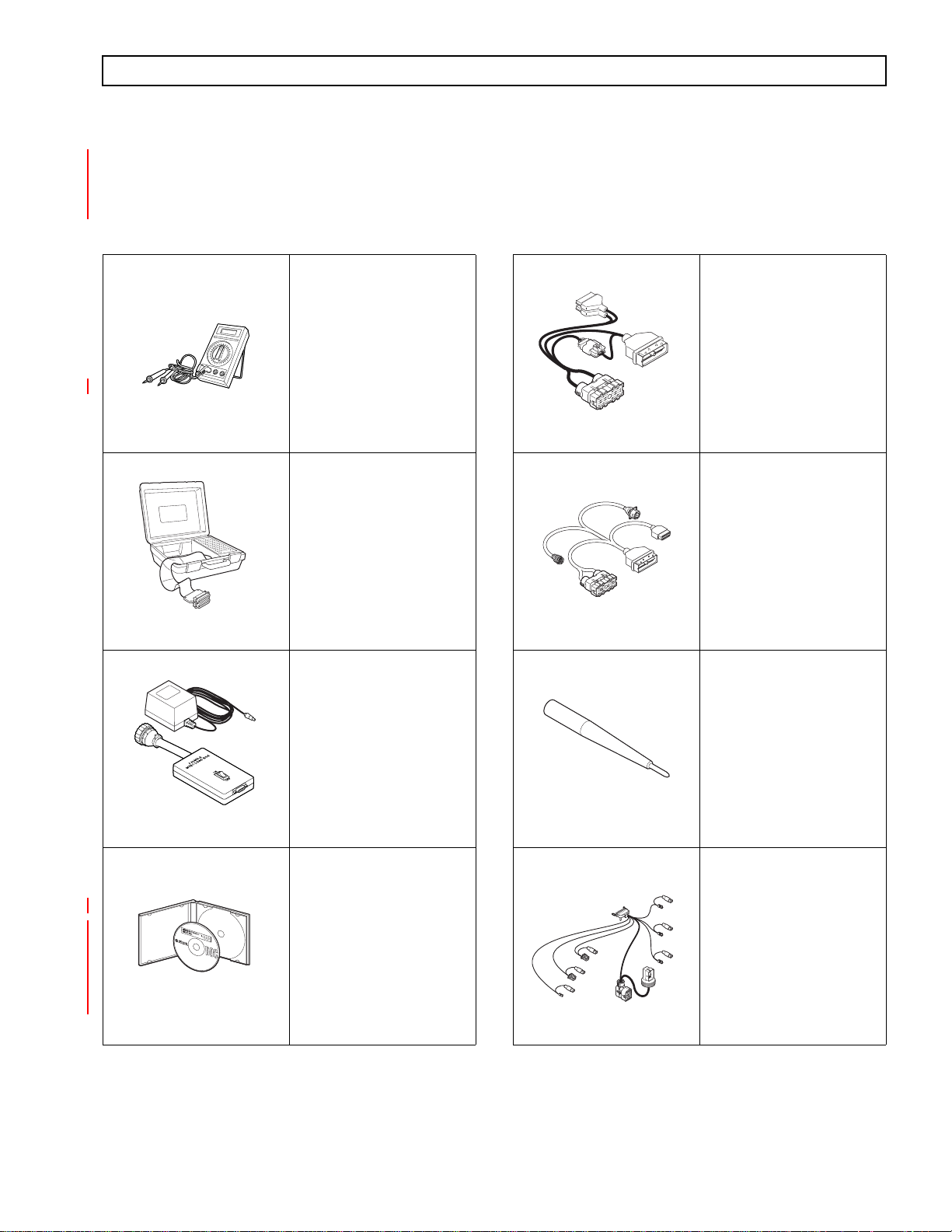
1–11. SPECIAL ELECTRONIC/ELECTRICAL TOOLS
All tools listed are essential for overhaul, maintenance, and/or recalibration of the 3000 and 4000 Product Families
electronic and electrical systems. The tools listed below are available for purchase from SPX/Kent-Moore.
Table 1–1. Essential Tools
3 4 of 9 D I G I T A L M U L T I M E T E R
40
50
100
500
200
300
300
900
400
600
2
5
7
200
500
300
600
400
500
500
700
600
x
COM
abcde
A
xyz ab
10 A
abcde
xyz ab
m
ultim
eter
J 39700
J 34520-A
Digital
Volt/Ohmmeter
J 39700
Univeral Breakout Box
TCM Breakout
Harness Adapter
NOTE: Used with J 39700.
J 47275
J 47276
“T” Breakout and TCM
Reflashing Harness
J 47276
J 47277
Terminal Probe
J 42455-A
J 47275
Load Box
NOTE: J 47277 is now
included in the J 39197-A
Kit.
J 42455-A
J 47277
J 44950
Allison DOC™ For
PC–Service Tool
NOTE: J 44950 is
superseded for each new
release of Allison DOC™
For PC–Service Tool
*
NOTE: 4000 Product Family
*
*
3000 and 4000 Product
Families Breakout Harness
V09224.01.00
J 44950
J 47279
Copyright © 2008 Allison Transmission, Inc. 1–19
Page 30

3000 AND 4000 PRODUCT FAMILIES TROUBLESHOOTING MANUAL—ALLISON 4th GENERATION CONTROLS
GENERAL DESCRIPTION
Table 1–1. Essential Tools (cont’d)
J 47943
J 39197-A
J 47943-A
or
J 47943
DPA4 (Plus) USB
Translator Device Kit
J 39197
or
J 39197-A
Jumper Kit
NOTE: J 47277 Terminal
Probe is now included in
the J 39197-A Kit.
Table 1–2. Available Tools
J 47949-A
or
J 47949
GMLAN Cable
J 47949
J 38125-12A
Terminal Remover
(80-way connector)
GM P/N: 12094429
J 38125-12A J 47139
J 47139 (Former)
63811-6000 (Current)
Crimper
1–20 Copyright © 2008 Allison Transmission, Inc.
Page 31

3000 AND 4000 PRODUCT FAMILIES TROUBLESHOOTING MANUAL—ALLISON 4th GENERATION CONTROLS
SECTION 2—DEFINITIONS AND ABBREVIATIONS
2–1. CHECK TRANS LIGHT
When the TCM detects a serious fault, the CHECK TRANS light (usually located on the vehicle instrument panel)
illuminates and action is automatically taken to protect operator, vehicle, and the transmission. A Diagnostic
Trouble Dode (DTC) will nearly always be registered when the CHECK TRANS light is on; however, not all
DTCs will turn on the CHECK TRANS light. Codes related to the CHECK TRANS light are detailed in the
diagnostic trouble code chart (refer to Section 6).
Illumination of the CHECK TRANS light indicates that a condition was detected that requires service attention.
Operation may or may not be restricted. Even when operation is restricted, the vehicle can be operated to reach a
service assistance location. Depending upon the cause for the CHECK TRANS light illumination, the TCM may or
may not respond to shift selector requests. The transmission may be locked in a range. That range will be shown on
the shift selector display. Both upshifts and downshifts may be restricted when the CHECK TRANS light is
illuminated. Seek service assistance as soon as possible.
Each time the engine is started, the CHECK TRANS light illuminates briefly and then goes off. This momentary
lighting shows the light circuit is working properly. If the light does not come on during engine start, request
service immediately.
A. Oil Life Monitor (OM)
The display message, seen in Allison DOC™ For PC–Service Tool or the Allison shift selector,
indicates the calculated remaining life of the transmission fluid. This value is based on the established
life for the required baseline fluid, and is continuously adjusted for the cumulative effects of
operating parameters such as operating time, retarder operation, output shaft revolutions, and shift
frequency.
OM Display: The selector display is a two-digit number, showing the percentage of fluid life
remaining. New fluid is displayed as 99 percent. Minimum value displayed is 00 percent. Allison
DOC™ For PC–Service Tool displays from 100 percent down to minus (–) 100 percent.
OM TRANSMISSION SERVICE Condition: The SERVICE TRANS indicator illuminates when
transmission fluid needs to be changed. This occurs when the remaining fluid life is approximately 1
percent. The indicator is lit upon each initialization of the TCM, and remains on for approximately 1–
2 minutes after the first selection of a drive range, until service is performed and the indicator is reset.
Failure to perform maintenance and reset the SERVICE TRANS indicator within a specified period
results in the illumination of the CHECK TRANS light and DTC P0897, Transmission Fluid
Deteriorated, being set. P0897 indicates the remaining fluid life has reached 1 percent.
OM Reset: The function may be reset by one of the following methods:
NOTE: Prognostic information can only be reset in the higher of two shift schedules, if applicable.
• Message over the SAE J1939 communication interface.
• With the ignition ON and the engine OFF, shift between N D N D N R N, pausing briefly (less
than 3 seconds) between shifts, to reset the value displayed on the shift selector to 99 percent.
• Display the Oil Life Monitor information and press and hold the MODE button of the Allison
shift selector for 10 seconds.
• Reset by using the specific Action Request in the Allison DOC™ For PC–Service Tool .
The SERVICE TRANS indicator illuminates briefly following a reset to acknowledge the reset was
successful.
Copyright © 2008 Allison Transmission, Inc. 2–1
Page 32

3000 AND 4000 PRODUCT FAMILIES TROUBLESHOOTING MANUAL—ALLISON 4th GENERATION CONTROLS
DEFINITIONS AND ABBREVIATIONS
Allison DOC™ For PC–Service T ool may be used to enable a Customer Modifiable Constant (CMC)
within the Prognostics CMC Group to restrict reset to the service tool only. If resets are restricted to
the service tool, the selector will not be able to reset the function.
OM History: A historical record of the last 6 resets, including mileage at the time of each reset, may
be viewed using the Allison DOC™ For PC–Service Tool .
NOTE: Required calendar-based fluid change intervals are not monitored by this function and those intervals
remain applicable to all vehicle installations in addition to the above.
B. Filter Life Monitor (FM)
Filter Life Monitor indicates when the filters require changing. The display message indicates the
operating status of the transmission main filter, based on the measured pressure drop across the filter.
The Prognostics pressure switch is activated when fluid exiting the main filter drops below a predetermined pressure. Both the main and lube filters must be changed when the SERVICE TRANS
indicates the main filter should be changed. The differential pressure limit is verified for a period of
time to make sure there is no false filters change indication. This feature is not functional until
transmission sump temperatures are between 40º–150ºC (105–302ºF). This feature is not available
with 7-speed transmission models.
FM Display: An acceptable filter life status is displayed as OK in the shift selector; an unacceptable
filter life status is displayed as LO. Allison DOC™ For PC–Service To ol indicates the Filter Life
Monitor expired as YES or NO.
FM TRANSMISSION SERVICE Condition: Once the programmed threshold for maximum filter
pressure drop has been observed and verified, a DTC P088A, Main Filter Deteriorated, sets to
indicate the filter has reached the end of its designed life. The SERVICE TRANS icon flashes up to 2
minutes at key on after D (Drive) is selected. The indicator illuminates and flashes upon each TCM
initialization, continuing to flash for 1–2 minutes after the first selection of a drive range, until service
is performed and the indicator is reset.
Failure to perform maintenance and reset the monitor after a calibration-defined number of warnings
results in the illumination of the CHECK TRANS light. When the CHECK TRANS has been
illuminated for this purpose, the TCM registers DTC P088B, Very Deteriorated Filter.
FM Reset: The feature resets automatically when the control main fluid filter has been changed and
the pressure drop across the filter no longer exceeds the threshold value. The lube filter must be
changed with the main filter.
The SERVICE TRANS indicator illuminates briefly following a reset to acknowledge the reset was
successful.
Manual resets may also be performed by one of the following methods:
• With the ignition ON and the engine OFF, shift between N R N R N D N to reset the value
displayed on the shift selector to OK.
• Display the Filter Life Monitor information and press and hold the MODE button of the Allison
shift selector for 10 seconds.
• Message over the SAE J1939 communication interface.
NOTE: The Filter Life Monitor triggers the SERVICE TRANS icon following a reset if the Filter Life
indicator switch reopens.
2–2 Copyright © 2008 Allison Transmission, Inc.
Page 33

3000 AND 4000 PRODUCT FAMILIES TROUBLESHOOTING MANUAL—ALLISON 4th GENERATION CONTROLS
DEFINITIONS AND ABBREVIATIONS
Allison DOC™ For PC–Service T ool may be used to enable a CMC (Customer Modifiable Constant)
within the Prognostics CMC Group to restrict reset to the service tool only. If resets are restricted to
the service tool, the selector will not be able to reset the function.
FM History: Use the Allison DOC™ For PC–Service Tool to display the amount of transmission
operation from the initial service indication until the service reset.
NOTE: Required calendar-based filter change intervals are not monitored by this feature and remain
applicable to all vehicle installations in addition to the above.
C. Operation of Filter Life Valve and Pressure Switch (PS2)
Pressure Switch 2 (PS2), also known as the Filter Life Switch, is used to monitor the pressure
difference between main pressure before the filter and lockup clutch pressure as a method to monitor
the main filter for excessive filter restriction. See Figure 1.
When the main filter is in an unrestricted state and lockup clutch pressure is applied, the switch is
depressurized and in its Normally closed (NC) position which completes a circuit between wire 118
and analog returns wire 158. Allison DOC™ For PC–Service Tool shows PS2 EXHAUSTED. The
Filter Life Valve is de-stroked off the return spring in this condition because lockup pressure is high
enough to keep main pressure (before the filter) from stroking the valve.
When the main filter gets excessively restricted by debris, lockup pressure drops. The Filter Life
Valve strokes because of the higher main pressure (before the filter). This acts on the other end of the
Filter Life Valve, compressing the return spring and allowing control main pressure through the valve
to PS2, which pressurizes the switch. This opens the PS2 and voltage is sensed on wire 118. Allison
DOC™ For PC–Service Tool shows PS2 PRESSURIZED.
Copyright © 2008 Allison Transmission, Inc. 2–3
Page 34

3000 AND 4000 PRODUCT FAMILIES TROUBLESHOOTING MANUAL—ALLISON 4th GENERATION CONTROLS
DEFINITIONS AND ABBREVIATIONS
MAIN CIRCUIT FILTER
FILTER LIFE VALVE
MAIN PRESSURE
(BEFORE FILTER)
PUMP
SUCTION FILTER
EX
SUMP
FILTERED
MAIN
FILTER LIFE VALVE HYDRAULIC SCHEMATIC
Figure 2–1. Filter Life Valve Hydraulic Schematic
D. Transmission Health Monitor (TM)
MAIN
FLOW
PS 2
EX
CONTROL MAIN
TCC FLOW
FILTERED
MAIN
LUBE
V11111.00.00
The display message, seen in Allison DOC™ For PC–Service T ool or the Allison shift selector,
identifies clutch life status, as determined by monitored changes and the calculated running clearance
of the transmission clutches C1, C2, C3, C4, and C5.
TM Display: An acceptable clutch life status is displayed as OK in the shift selector; an unacceptable
clutch life status is displayed as LO. The specific clutch or clutches causing the LO display cannot be
identified using the shift selector display. Allison DOC™ For PC–Service Tool displays clutch
condition as OK or NOT OK for each clutch, C1 through C5. Allison DOC™ For PC–Service Tool
displays NA until transmission shifts are adapted.
TM TRANSMISSION SERVICE Condition: The SERVICE TRANS indicator illuminates,
indicating the need for clutch maintenance. This occurs when the remaining clutch life reaches
2–4 Copyright © 2008 Allison Transmission, Inc.
Page 35

3000 AND 4000 PRODUCT FAMILIES TROUBLESHOOTING MANUAL—ALLISON 4th GENERATION CONTROLS
DEFINITIONS AND ABBREVIATIONS
approximately 10 percent or the running clearance exceeds a maximum value, which may indicate a
non-wear-related issue. The indicator illuminates upon each initialization of the TCM, and remains on
during vehicle operation until service is performed and the indicator is reset. Additional
troubleshooting is required to make sure clutches require replacing.
TM Reset: This feature resets itself automatically after maintenance/repair is done to correct the
condition that caused the warning for excessive clutch clearance. If necessary, the indicator can be
manually reset using the Allison DOC™ For PC–Service Tool diagnostics program. After a number
of warnings occur from the SERVICE TRANS indicator without correcting the condition, the
CHECK TRANS light illuminates and DTC P2789, Clutch Adaptive Learning at Limit, activates.
TM History: Use the Allison DOC™ For PC–Service T o ol to display the amount of transmission
operation from the initial service indication until the service reset.
2–2. ALLISON TRANSMISSION DIAGNOSTIC TOOL
Allison DOC™ (Diagnostic Optimized Connection) For PC–Service Tool is a PC-based diagnostic tool for use
with 3000 and 4000 Product Families transmissions. The Allison DOC™ For PC–Service Tool is a full-feature
diagnostic software application supporting the Allison 4
own PC, it will allow the technician to acquire data from the transmission’s control system and through the use of
embedded troubleshooting manuals, conduct systematic troubleshooting of transmission complaints.
th
Generation Control System. When installed on the user’s
Basic Features
Allison DOC™ For PC–Service Tool uses a Windows
• User selected views of multiple transmission parameters
• Active and historical diagnostic trouble codes (DTCs)
• Graphical instrument panel view of transmission parameters
• Strip chart function
• User configurable Snapshot function
• User configurable Print function
• Code driven links to embedded Allison 4
• Reprogramming capability (available after satisfying Allison Transmission training certification
th
requirements)
• Demo Mode which allows the user to practice the program without being connected to a vehicle
• New animated screen by screen help support (found in Help, V ideo-based training materials, Allison
DOC™ For PC–Service To ol Training Videos)
• Application Configuration—This menu function serves as the platform for three different features:
(1) General tab, which allows the user to select language (English only at this time), and unit of measure.
(2) TCM Reprogramming tab, used to enable the reprogramming capability of the Allison DOC™ For
PC–Service Tool .
(3) Update Application tab, which provides access to a URL containing minor updates for the diagnos-
tic tool to support changes in the various transmission control systems.
• Data Bus Viewer allows the user to capture (see and save) the raw data transmitted on the various
vehicle data buses supported by Allison DOC™ For PC–Service Tool (J 1939 and J 2284)
• Printed user’s manual and laminated Job Aid Card
• Adobe
• Microsoft
Acrobat Reader® bundled on the CD for reading the Troubleshooting Manual
Media Player bundled on the CD for displaying various and updated training videos
(available from the application Help menu).
style graphical user interface (GUI) and includes:
Generation Control System Troubleshooting Manuals
Copyright © 2008 Allison Transmission, Inc. 2–5
Page 36

3000 AND 4000 PRODUCT FAMILIES TROUBLESHOOTING MANUAL—ALLISON 4th GENERATION CONTROLS
DEFINITIONS AND ABBREVIATIONS
PC Platform Definition
Allison DOC™ For PC–Service Tool V7.x.x has been tested with and is known to operate on PCs with the
following configurations*:
• Microsoft Windows XP® Professional, Wind ows 2000 (SP4 or later) Professional, and Windows
Vista™ Home Basic (or better)
NOTE: In order to install and run Allison DOC for PC–Service Tool V7.x.x on Windows Vista™, the user
must have full administrator privileges and must have the User Acount Control feature turned OFF.
• 20 GB Hard Drive (40 GB or greater recommended)
• 600 MB free hard drive space required to install the program (after software installation, the operating
system requires sufficient free hard disk dpace to run the program)
• 1 GHz (or greater) 32-bit (x86) or 64-bit (x64) processor
• 512 MB of RAM system memory (1 GB recommended)
• One available USB port—USB 1.1 (USB 2.0 recommended)
• 16x CD-ROM (48x or greater recommended)
• Full administrative privileges are required to install, update, and run Allison DOC™ For PC–Service
Tool
• Internet connection capability with Internet Explorer® 5.0.1 or greater.
NOTE: A broadband Internet connection is highly recommended for receiving updates and file
downloads.
• Windows Media® Player is installed by default
• Adobe® Acrobat Reader® is installed by default
NOTE: Error messages, sudden disconnections, and poor performance are some of the results users will
experience if Allison DOC
For PC-Service Tool V7.x.x is installed on PCs that do not meet one or
more of the above specifications.
NOTE: For the latest requirements, please refer to www.allisontransmission.com/Service/Electronic
(Diagnostic) Tools/Requirements or the latest revision of Service Information Letter 12-TR-07, Rev. A.
2–6 Copyright © 2008 Allison Transmission, Inc.
Page 37

3000 AND 4000 PRODUCT FAMILIES TROUBLESHOOTING MANUAL—ALLISON 4th GENERATION CONTROLS
DEFINITIONS AND ABBREVIATIONS
2–3. ABBREVIATIONS
A/N Assembly Number
ABS Anti-lock Brake System—OEM-provided means to detect and prevent wheel stoppage to
enhance vehicle handling. Retarder and engine brakes will not apply when ABS is active.
Amp Unit of electrical current
API Application Program Interface
AT Allison Transmission
C1...C6 Clutch 1....Clutch 6
CAN Controller Area Network—A network for all SAE J1939 communications in a vehicle
(engine, transmission, ABS, etc.)
CIN Calibration Identification Number
CMC Customer Modified Constant
CPA Connector Position Assurance
CT Closed Throttle
DCE Direction Change Enable
DMM Digital Multimeter
DNA Does Not Adapt—Adaptive shift control is disabled
DNS DO NOT SHIFT—Refers to the DO NOT SHIFT diagnostic response during which the
CHECK TRANS light is illuminated and the transmission will not shift and will not
respond to the Shift Selector
DOC Diagnostic Optimized Connection
DPA Dearborn Protocol Adapter
DTC Diagnostic Trouble Code
DVOM Digital Volt/Ohmmeter
ECM Engine Control Module
EMI ElectroMagnetic Interference
FBO F eature Based Ordering
FCC Federal Communications Commission
FM Filter Life Monitor
GPI General Purpose Input—Input signal to the TCM to request a special operating mode or
condition
GPO General Purpose Output—Output signal from the TCM to control vehicle components
(such as PTOs, backup lights, etc.) or allow a special operating mode or condition
GUI Graphical User Interface
HSD High Side Driver
J1587 Engine/transmission serial data communications link
J1939 High-speed vehicle serial data communications link
Copyright © 2008 Allison Transmission, Inc. 2–7
Page 38

3000 AND 4000 PRODUCT FAMILIES TROUBLESHOOTING MANUAL—ALLISON 4th GENERATION CONTROLS
DEFINITIONS AND ABBREVIATIONS
2–3. ABBREVIATIONS (cont’d)
LED Light-Emitting Diode—Electronic device used for illumination
LRTP Low Range Torque Protection
LSD Low Side Driver
MB Mega Byte
NNC Neutral No Clutches—Neutral commanded with no clutches applied
NVL Neutral Very Low—The TCM has sensed turbine speed below 150 rpm when output speed
is below 100 rpm and engine speed is above 400 rpm when N (Neutral) was selected. This
is usually caused by a dragging C1 or C3 clutch or a failed turbine speed sensor. NVL is
attained by turning D solenoid “ON” (in addition to E solenoid) and the C4 and C5
clutches are applied to lock the transmission output.
OEM Original Equipment Manufacturer—Maker of vehicle or equipment
Ohm Unit of electrical resistance
OL Over Limit or Oil Level—For Over Limit see “”. Indicates Oil Level is being displayed
on a shift selector
OLS Oil Level Sensor—Electronic device (optional) on control module for indicating
transmission fluid level
OM Oil Life Monitor
PC Personal Computer
PCCS PROM Calibration Configurator System
PCS Pressure Control Solenoid
PLR Primary Lock Reinforcement (Connector)
P/N Part Number
PROM Programmable Read Only Memory
PSS Primary Shift Selector—Main shift selector in a two-selector control system.
PTO Power Takeoff
PWM Pulse Width Modulation
RELS Reduced Engine Load at Stop
RFI Radio Frequency Interference
RMR Retarder Modulation Request—Signal from a retarder control device
RPR Return to Previous Range—Diagnostic response in which the transmission is commanded
to return to previously commanded range
RTDR Retarder
SCI Serial Communication Interface—Used to transmit data and messages between the
diagnostic tool and the TCM and other systems such as electronically-controlled engines.
SCTI St. Clair Technologies, Inc.
SEM Shift Energy Management
2–8 Copyright © 2008 Allison Transmission, Inc.
Page 39

3000 AND 4000 PRODUCT FAMILIES TROUBLESHOOTING MANUAL—ALLISON 4th GENERATION CONTROLS
DEFINITIONS AND ABBREVIATIONS
2–3. ABBREVIATIONS (cont’d)
S/N Serial Number
SOH State Of Health
SOL OFF All SOLenoids OFF
SPI Serial Peripheral Interface—The means of communication between the microprocessor
and the interface circuits
SS Shift Solenoid
SSS Secondary Shift Selector—Alternate shift selector in a two-selector control system
TCC Torque Converter Clutch
TCM Transmission Control Module
TFT Transmission Fluid Temperature
TID TransID—A feature which allows the TCM to know the transmission configuration and
provide the corresponding calibration required
TM Transmission Health Monitor
TPA Terminal Position Assurance
TPS Throttle Position Sensor—Potentiometer for signaling the position of the engine fuel
control lever
V Version—Abbreviation used in describing TCM software levels
VDC Volts Direct Current (DC)
VF Vacuum Fluorescent
VIM Vehicle Interface Module—A watertight box containing relays and fuses—interfaces the
transmission electronic control system with components on the vehicle
VIW Vehicle Interface Wiring—Interfaces TCM programmed input and output functions with
the vehicle wiring
Volt Unit of electrical force
WOT Wide Open Throttle
Infinity—Condition of a circuit with higher resistance than can be measured, effectively an
open circuit
Copyright © 2008 Allison Transmission, Inc. 2–9
Page 40

3000 AND 4000 PRODUCT FAMILIES TROUBLESHOOTING MANUAL—ALLISON 4th GENERATION CONTROLS
DEFINITIONS AND ABBREVIATIONS
2–10 Copyright © 2008 Allison Transmission, Inc.
Page 41

3000 AND 4000 PRODUCT FAMILIES TROUBLESHOOTING MANUAL—ALLISON 4th GENERATION CONTROLS
SECTION 3—BASIC KNOWLEDGE
3–1. BASIC KNOWLEDGE REQUIRED
To service Allison 4th Generation Controls, the technician must understand basic electrical concepts. Most
troubleshooting tests consist of determining resistance, continuity, and testing for shorts between wires and to
ground. Technicians need to know how to use a digital volt/ohmmeter (DVOM) to make resistance and continuity
tests. The technician should be able to use jumper wires and breakout harnesses and connectors. Technicians
unsure of making the required tests should ask questions of experienced personnel or find instruction.
The technician should also have the mechanical aptitude required to connect pressure gauges or transducers to
identified pressure ports used in the troubleshooting process. Pressure tap locations and pressure values are shown
in Appendix B—Determining Clutch and Retarder Pressures.
Input power, ground , neutral start circuitry, etc., can cause problems with electronic controls or vehicle functioning
th
and may not generate a DTC. A working knowledge of the Allison 4
Generation Controls vehicle installation is
necessary in troubleshooting installation-related problems.
Refer to Section 8 for information concerning performance complaints (non-code) troubleshooting. A complete
wiring schematic is shown in Appendix J. Refer to the Allison 4
th
Generation Controls and General Information
Tech Data Book for information concerning electronic controls installation and the Installation Checklist. Reliable
transmission operation and performance depend upon a correctly installed transmission. Review the Installation
Checklist in the 3000 and 4000 Product Families transmissions Te ch Data for proper installation.
NOTE: Allison Transmission is providing for service of wiring harnesses and wiring harness components as
follows:
• Repair parts for the internal wiring harness and for wiring harness components attached to the
shift selector will be available through the Allison Transmission Parts Distribution Center (PDC).
Use the P/N from your appropriate parts catalog or from Appendix E in this manual. Allison
Transmission is responsible for warranty on these parts.
• Repair parts for the external harnesses and external harness components must be obtained from
St. Clair Technologies Inc. (SCTI). SCTI provides parts to any Allison customer or OEM and is
responsible for warranty on these parts. SCTI recognizes Allison Transmission, manufacturers,
and SCTI part numbers. SCTI provides a technical HELPLINE at 519-627-1673 (Wallaceburg).
SCTI will have parts catalogs available. The SCTI addresses and phone numbers for parts
outlets are:
St. Clair Technologies, Inc.
920 Old Glass Road
Wallaceburg, Ontario, Canada N8A 4L8
Phone: 519-627-1673
Fax: 519-627-4227
St. Clair Technologies, Inc.
Calle Damanti S/N Col
Guadalupe—Guaymas
Sonora, Mexico 85440
Phone: 011-526 2222-43834
Fax: 011-526-2222-43553
3–2. USING THE TROUBLESHOOTING MANUAL
Use this manual as an aid to troubleshooting the Allison 4th Generation Controls. Every possible problem and its
solution cannot be encompassed by any manual. However, this manual does provide a starting point from which
most problems can be resolved.
Once a problem solution is discovered in the manual do not look further for other solutions. It is necessary to
determine why a problem occurred. The root cause of a problem as well as the symptom must be corrected to be
sure of trouble-free operation. For example, taping a wire that has been rubbing on a frame rail will not correct the
problem unless the rubbing contact is eliminated.
Copyright © 2008 Allison Transmission, Inc. 3–1
Page 42

3000 AND 4000 PRODUCT FAMILIES TROUBLESHOOTING MANUAL—ALLISON 4th GENERATION CONTROLS
BASIC KNOWLEDGE
3–3. SYSTEM OVERVIEW
Allison 4th Generation Control functions are controlled by the TCM. The TCM reads the following to determine
when to command a shift:
• Shift selector range selection
• Output speed
• Throttle position.
In order to control the oncoming and off-going clutches during a shift, the TCM monitors:
• Turbine speed
• Output speed
• Throttle position.
When the TCM detects an electrical fault, it logs a DTC indicating the faulty circuit and may alter the transmission
operation to prevent or reduce damage.
When the TCM detects a non-electrical problem while trying to make a shift, the TCM may try that shift a second
or third time before setting a DTC. Once that shift has been retried, and a fault is still detected, the TCM sets a DTC
and holds the transmission in a fail-to-range mode of operation.
3–4. IMPORTANT INFORMATION IN THE TROUBLESHOOTING PROCESS
A. Before Beginning Troubleshooting
Before beginning the troubleshooting process, read and understand the following :
• Allison Transmission recommended wire numbers (i.e. 158) all use a “1” for the first digit and the
pin-out information at the TCM for the second and third digits.
• Shut off the engine and ignition before any harness connectors are disconnected or connected.
• Remember to do the following when testing for shorts and opens:
— Minimize movement of wiring harnesses when looking for shorts. Shorts involve wire-to-wire
or wire-to-ground contacts and moving the harnesses may eliminate the problem.
— Wiggle connectors, harnesses, and splices when looking for opens. This simulates vehicle
movements which occur during actual operation.
• When disconnecting a harness connector, be sure the pulling force is applied to the connector itself
and not the wires extending from the connector.
• Resistance tests involving wiring between the TCM connector and other components adds about
one Ohm of resistance to the component resistance shown.
• Inspect all connector terminals for damage. Terminals may have been bent or lost the necessary
tension to maintain firm contact.
• Clean dirty terminals or connectors with isopropyl alcohol and a cotton swab, or a good quality,
non-residue, non-lubricating, cleaning solvent such as LPS Electro Contact Cleaner
®
NoFlash Electro Contact Cleaner
3–2 Copyright © 2008 Allison Transmission, Inc.
.
®
or LPS
Page 43

3000 AND 4000 PRODUCT FAMILIES TROUBLESHOOTING MANUAL—ALLISON 4th GENERATION CONTROLS
BASIC KNOWLEDGE
The cleaning solvent must not be:
• Chlorine based
• Contain petroleum distillates
CAUTION:
• Conduct electricity.
The cleaning solvent should evaporate quickly to prevent the possibility of
condensation within the connectors. Always blow or shake any excess cleaner from
the connector before assembling it to its mating connector or hardware. Cleaner
trapped in the connector can affect the connector seal. Refer to SIL 17-TR-94, latest
revision, for detailed information on the recommended cleaners.
CAUTION:
• DTCs displayed after system power is turned on with a harness connector disconnected, can be
Care should be taken when welding on a vehicle equipped with electronic controls.
Refer to Appendix G, Paragraph 1–1.
ignored and cleared from memory. Refer to Section 6, Diagnostic Trouble Codes, for the code
clearing procedure.
NOTE: Turn off the vehicle HIGH IDLE switch, if present, before shifting from N (Neutral) to D (Drive).
D (Drive) or R (Reverse) will not be attained unless the shift is made with the engine at idle. Also, be
aware of other interlocks that would prevent attaining D (Drive) or R (Reverse). Examples are
“wheelchair lift not stored” and “service brakes not applied” (service brake interlock present).
B. Cold Weather Starts
All Highway Series transmissions are programmed to restrict full operation until specific fluid
temperatures are reached. Refer to the Table 3–1 for temperature restrictions.
Table 3–1. Minimum Fluid Operating Temperatures
Sump Fluid Temperature
CHECK TRANS
Light
Operation
–32ºC to –7ºC (–25ºF to 19ºF) OFF Neutral, Reverse, Second
–7ºC (19ºF) OFF Full operation in all ranges
NOTE: When sump temperature is below 10ºC (50ºF) and transmission fluid is C4 (not DEXRON
TranSynd™), follow these procedures when making directional shift changes:
• To shift from forward to reverse, select N (Neutral) and then R (Reverse).
• To shift from reverse to forward, select N (Neutral) and then D (Drive) or other forward range.
Failure to follow these procedures may cause illumination of the CHECK TRANS light and the
transmission will be restricted to N (Neutral).
Transmission operation at cold ambient temperatures may require preheating or the use of a lower
viscosity transmission fluid.
Copyright © 2008 Allison Transmission, Inc. 3–3
®
or
Page 44

3000 AND 4000 PRODUCT FAMILIES TROUBLESHOOTING MANUAL—ALLISON 4th GENERATION CONTROLS
BASIC KNOWLEDGE
C. High Fluid Temperature
The transmission is considered to be overheated when any of the temperatures in Table 3–2 are
exceeded:.
Table 3–2. Maximum Allowable Transmission Fluid Temperature
Location of Fluid Temperature
If the transmission overheats during normal operation, use the Oil Level Sensor (OLS), if equipped,
to check for correct fluid level. Refer to Section 5-2 for this procedure.
CAUTION:
If the engine temperature gauge indicates a high temperature, the transmission is probably
overheated. Stop the vehicle and inspect the cooling system. If it appears to functioning p[roperly , run
the engine at 1200
transmission and engine temperature to normal operating levels in two to three minutes. If
temperatures do not decrease, reduce the engine rpm.
If the engine temperature indicates a high temperature, an engine or radiator problem is indicated. If
high temperature in either the engine or transmission persists, stop the engine and have the
overheating condition investigated by maintenance personnel.
Sump fluid 121
Fluid to cooler 149
Retarder out fluid 165
The engine should never be operated for more than ten (10) seconds at full throttle
with the transmission in range and the output stalled. Prolonged operation of this
type will cause the transmission fluid temperature to become excessively high and
will cause severe overheat damage to the transmission.
ºC (250ºF)
ºC (300ºF)
ºC (330ºF)
–1500 rpm with the transmission in N (Neutral). This should reduce the
3–5. BEGINNING THE TROUBLESHOOTING PROCESS
NOTE:
• Whenever a transmission is overhauled, exchanged, or has undergone internal repairs, the TCM MUST
BE RESET TO FACTORY VALUES by selecting “Reset To Unadapted Shifts” (all), and “Reset
Autodetect Information” in Allison DOC
• Be sure the transmission model matches the calibration in the TCM.
1. Begin troubleshooting by determining the transmission fluid level and TCM input voltage. Remember that some problems may be temperature related. Do troubleshooting at the temperature level
where the problem occurs. Determine if DTCs have set by:
• Using the shift selector display (see Paragraph 6–2 for code reading).
• Using the Allison DOC For PC–Service Tool.
2. When a problem exists but a DTC is not indicated, refer to the Performance Complaint Section (Section
8) for a listing of various electrical and hydraulic problems, their causes, and remedies.
3. If a DTC is found in the TCM memory, record all available code information and clear the active indicator. Refer to Section 6.
3–4 Copyright © 2008 Allison Transmission, Inc.
For PC–Service Tool.
Page 45

3000 AND 4000 PRODUCT FAMILIES TROUBLESHOOTING MANUAL—ALLISON 4th GENERATION CONTROLS
BASIC KNOWLEDGE
4. Test drive the vehicle to confirm a DTC or performance complaint.
• If the code reappears, refer to Section 6, Diagnostic Trouble Code, and the appropriate code chart.
The Diagnostic Trouble Code section lists DTCs and their description. Locate the appropriate
troubleshooting chart and follow the instructions.
• If the code does not reappear, it may be an intermittent problem. Use the Allison DOC For PC–
Service Tool and the code display procedure described in Section 6. The code display procedure
will indicate the number of times the DTC has occurred. Refer to the troubleshooting chart for the
possible cause(s) of the problem.
• Appendix A deals with the identification of potential circuit problems. Refer to Appendix A if a
circuit problem is suspected.
5. If difficulties arise, you have unanswered questions, or if you are unable to quickly identify the root
cause during troubleshooting, please contact the Technical Assistance Center (TAC):
Technical Assistance Center
PO Box 894, Mail Code A01
Indianapolis, IN 46206-0894
Phone: 1-800-252-5283
NOTE: Information concerning specific items is contained in the appendices located in the back of this
manual. The appendices are referred to throughout the manual.
3–6. TCM DIAGNOSTIC PROCEDURE
• Use the Allison DOC For PC–Service T ool to verify the current calibration information number (CIN)
and record or print a report of the current customer modifiable constants (CMC) information for later
reference.
• Remove the 80-way connector from the suspect TCM; inspect the connector for damaged or bent pins.
• Replace the TCM with a known, good TCM from a similar vehicle.
NOTE: If using a TCM from another vehicle is unavoidable, the TCM MUST BE set to factory values and the
vehicle MUST BE driven carefully to adapt the shifts to the test vehicle. Refer to SIL 16-WT-96 for the
correct procedure. Be sure to reset the Adaptive Shift parameters and Autodetect information when it
is installed in the original vehicle.
• If the replacement TCM corrects the original complaint, reinstall the original TCM to verify that the
complaint returns. If the complaint is confirmed. install a new TCM.
• If the complaint does not return, leave the original TCM installed. Disconnecting and reconnecting the
TCM can often correct faulty wiring harness connections that may have been present.
• Clear any DTCs that may be present and test drive the vehicle to confirm the repair.
NOTE: All Allison 4
Be sure that the TCM case is not contacting the vehicle or any other point that might provide a ground
connection.
th
Generation Controls TCMs are designed to be isolated from the vehicle chassis ground.
Copyright © 2008 Allison Transmission, Inc. 3–5
Page 46

3000 AND 4000 PRODUCT FAMILIES TROUBLESHOOTING MANUAL—ALLISON 4th GENERATION CONTROLS
BASIC KNOWLEDGE
3–7. RESETTING A TCM PARAMETERS TO SUPPORT ENGINE UPDATE
Shift Energy Management (SEM) Autoselect feature may be used on certain transmissions. Autoselect is
deactivated following the first 20 engine starts where engine and transmission communication are present. If
during the first 20 starts the TCM recognizes an engine to be on its list of certified engines, it will lock to the SEM
active state. If the engine is not supported, the TCM will lock to a non-SEM state.
NOTE: Most engine upgrades are same type/rating; under normal circumstances there should be no reason
to reset the TCM Autoselect.
However, there may be a small chance that transmission performance, shift quality, or codes may result from the
use of different models within the same engine family or when a recalibration of engine software has taken place. If
a vehicle receives upgraded engine hardware or software it may become necessary to reactivate the Autoselect
feature to redetect the engine current SEM status.
NOTE: Once TCM Autoselect locks, the only way to reactivate is to perform a reset procedure (refer to
Paragraph 3–8).
3–8. RESETTING TCM AUTOSELECT
Verify a new engine rating by checking the engine data tag. The engine must be compatible with the transmission
rating. If engine rating is not compatible, the vehicle must be returned to the OEM for engine recalibration. If the
rating is correct for the transmission, perform the following steps.
Allison DOC
The TCM is now reset to Autoselect and will start looking for supporting engine software. Drive the vehicle;
confirm DTCs have not returned.
NOTE: Transmission shifts will now be in the unadaptive (base) state, so it will be necessary to drive the
for PC–Service Tool is used to reset Autoselect function as follows:
• Display the Action Request menu.
• On the drop down menu, select Reset SEM Autodetect.
• Click on the OK button.
vehicle to allow shift to converge.
3–9. HYDRAULIC OPERAT ION DURING ELECTRICAL INTERRUPTION
NOTE: The terms left, right, up, and down are directions on the figures and hydraulic schematics referenced
by the descriptions in this section.
The solenoid regulator valves are controlled by solenoids that control transmission clutch application. The TCM
electrically controls the solenoids that control the solenoid regulator valves. Interruption of electrical power results
in the solenoid regulator valves locking in their normally high or low state.
The system that enables the transmission to default to totally hydraulic operation has been incorporated to
minimize the impact of an electrical interruption. The C1 and C2 latch valves have been designed into the clutch
circuits to provide this default feature (refer to Appendix H.).
When a clutch is applied, clutch feed pressure is routed through the latch valves to the clutch piston. Clutch-apply
pressure against the lands of the latch valves hold the latch valves in place or in a normally closed valve allows the
fluid to simply flow through the valves. During an electrical interruption, the latch valves cause the transmission to
engage specific clutches based on the range in which the transmission was operating when the interruption
occurred.
3–6 Copyright © 2008 Allison Transmission, Inc.
Page 47

3000 AND 4000 PRODUCT FAMILIES TROUBLESHOOTING MANUAL—ALLISON 4th GENERATION CONTROLS
BASIC KNOWLEDGE
The latch valves (refer to Appendix H) are activated by normally low solenoid SS1. When SS1 is energized,
control main pressure flows to the top of C1 and C2 latch valves. This pressure forces the valves down to connect
the necessary flow passages for clutch engagement. The exception is when C5 clutch is applied. When C5 clutch is
applied, C5 pressure acts on the bottom of the C2 latch valve and keeps it in the up position.
During an electrical interruption, the latch valves and two normally high, PCS1 and PCS2, enable the transmission
to operate in a “limp mode”, allowing the operator to drive the vehicle to a location where it can be serviced.
On 7-speed models, SS2 latch valve takes the place of C5 on the bottom of the C2 latch valve. When SS2 is on, the
valve is kept up by SS2.
The default system enables the transmission to revert to total hydraulic operation and provides safe operation
during an electrical interruption by shifting to a specific pre-determined range.
T able 3–3 lists the operating range and pre-determined default range the transmission will shift to in the event of an
electrical interruption.
Table 3–3.
Initial Operating Range
Reverse
Neutral
Hydraulic Default Range*
(Power Off; All Solenoids OFF)
Neutral
(C3 Clutch Applied)
Neutral
(C3 Clutch Applied)
Low (7-speed only) 3
13
2
3 (during shift to 2
4 (following shift)
34
44
54
6
* Some transmissions used in oil field service default to neutral
when power is OFF.
4 (during shift to 6
5 (following shift)
nd
)
th
)
Copyright © 2008 Allison Transmission, Inc. 3–7
Page 48

3000 AND 4000 PRODUCT FAMILIES TROUBLESHOOTING MANUAL—ALLISON 4th GENERATION CONTROLS
BASIC KNOWLEDGE
NOTES
3–8 Copyright © 2008 Allison Transmission, Inc.
Page 49

3000 AND 4000 PRODUCT FAMILIES TROUBLESHOOTING MANUAL—ALLISON 4th GENERATION CONTROLS
SECTION 4—WIRE TEST PROCEDURES
4–1. TESTING FOR OPENS, SHORTS BETWEEN WIRES, AND SHORTS-TO-GROUND
(Use Digital Volt/Ohmmeter J 34520-A and Jumper Wire Set J 39197 or J 39197-A)
NOTE: Please refer to Paragraph 3–5 to begin the troubleshooting process.
1. Make sure all connectors are tightly connected and re-test the circuit.
2. Disconnect and inspect all connectors.
Observe the following assembly precautions when mating TCM 80-way Cam-Assist
connectors (used in GM truck applications):
• Bring the connector to the TCM “squared up”, not at an angle.
• Keep hands away from the handle, squarely press the connector onto the
CAUTION:
Failure to do so could cause damage to the internal latching mechanism.
TCM until the cam lever handle moves of its own accord approximately
3
⁄4 inch.
• Gently complete mating the connector to the TCM by moving the cam lever
handle to the locked position.
• Slide the CPA into the secondary lock.
3. Thoroughly clean corroded or dirty terminals. If dirty or corroded terminals are the probable cause of
the problems, reconnect the clean connectors and operate the vehicle normally. If the problem recurs,
proceed with Step (4).
The cleaning solvent must not be:
• Chlorine based
• Contain petroleum distillates
• Conduct electricity.
CAUTION:
The cleaning solvent should evaporate quickly to prevent the possibility of
condensation within the connectors. Always blow or shake any excess cleaner from
the connector before assembling it to its mating connector or hardware. Cleaner
trapped in the connector can affect the connector seal. Refer to SIL 17-TR-94, latest
revision, for detailed information on the recommended cleaners.
4. Review the Allison 4
th
Generation Controls wire numbering system described in Paragraph 3–4.
5. If all connectors are clean and connected correctly, determine which wires in the chassis harness are
indicated by the DTC. For example, Code P0960, indicates an open in the pressure control solenoid
circuit, wires 111 and 174.
a. Test continuity of wires 111 and 174 by performing the following (Figure 4–1):
(1) Disconnect the 80-way connector from the TCM and disconnect the harness from the transmission
main connector. At one end of the harness, us ing jumper wire kit J 39197 or J 39197-A, connect
wires 111 and 174 to each other, being careful not to distort the terminals. Jumpering the wires
together creates a circuit between wires 111 and 174.
CAUTION:
Do not insert test probes larger than 0.81 mm into the TCM 80-way and
transmission 20-way connectors. Use the gray-colored 150 Series Metripack
Flexible Male Connector probe contained in Jumper W ire Kit J 39197 or J 39197-A
when testing the TCM and transmission mating connectors. Failure to do so may
distort the socket terminals inside the connectors and cause them to lose the
necessary tension to maintain firm contact.
Copyright © 2008 Allison Transmission, Inc. 4–1
Page 50

3000 AND 4000 PRODUCT FAMILIES TROUBLESHOOTING MANUAL—ALLISON 4th GENERATION CONTROLS
WIRE TEST PROCEDURES
(2) On the opposite end of the harness, test the continuity of the jumpered pair. No continuity in a
jumpered pair circuit (infinite resistance reading) indicates an open in the wire being tested.
Locate and repair the damaged portion of the wire.
b. If the continuity test is good (0–2 Ohms resistance), remove the jumpers. Test the ha rness for
shorts between wires and shorts-to-ground by performing the following (Figure 4–2):
(1) At the TCM end of the harness, touch one probe of a digital volt/ohmmeter (DVOM) to one
wire of the circuit being tested and touch the other probe to each terminal in the same connector, then touch the probe to chassis ground and to the transmission main housing. Do this for
both wires in the circuit being tested.
(2) If at any time the DVOM shows zero to low resistance, or the meter’s continuity beeper sounds,
there is a short between the two points being probed—wire-to-wire or wire-to-ground. Isolate
and repair the short.
BULKHEAD CONNECTOR
WIRING HARNESS
FEEDTHROUGH
HARNESS
CONNECTOR
DIGITAL
VOLT/OHM-METER
(DVOM)
JUMPER
0
–
+
WIRING HARNESS
0
–
+
Two wires have frayed and are shorted together.
Continuity beeper of DVOM will sound,
or reading will go to zero Ohms when these
two wires are probed with the DVOM.
0 OHMS OHMS
Circuit has continuity.
Jumper between wires produces
a complete circuit.
DVOM reading is near zero Ohms.
TRANSMISSION CONNECTOR
TCM
80-WAY
CONNECTOR
DIGITAL VOLT/OHM-METER
(DVOM)
Figure 4–2. Shor t Between Wires and to Ground
Figure 4–1. Open Circuit
Wires shorted
together
0
–
+
shorted-to-ground. DVOM continuity beeper will sound,
or reading will go to zero Ohms when meter is probing
0
–
+
Circuit does not have continuity due
to a broken wire (open circuit).
DVOM reading is very high
(infinite Ohms or OL – overlimit).
Shorted to
ground on
metal frame
rail
Ground
to metal
frame rail
0 OHMS0 OHMS
Harness has been chafed and one or more wires are
between this wire and chassis ground.
V03374.02.00
V03375.01.00
4–2 Copyright © 2008 Allison Transmission, Inc.
Page 51

3000 AND 4000 PRODUCT FAMILIES TROUBLESHOOTING MANUAL—ALLISON 4th GENERATION CONTROLS
WIRE TEST PROCEDURES
4–2. TESTING AT TRANSMISSION FEEDTHROUGH CONNECTOR FOR INTERNAL
HARNESS OPENS, SHORTS BETWEEN WIRES, AND SHORTS-TO-GROUND
1. Disconnect the external wiring harness from the transmission.
2. Inspect the connectors. Any terminals which are corroded or dirty must be thoroughly cleaned.
The cleaning solvent must not be:
• Chlorine based
• Contain petroleum distillates
CAUTION:
3. If the connectors are clean and connected correctly, determine which wires in the harness to test.
Use the DTC system schematic to locate the wire terminals. For this example, Code P0960 indicates
an open in the Main Mod solenoid circuit, wires 111 and 174 (Figures 4–3 and 4–4).
• Conduct electricity.
The cleaning solvent should evaporate quickly to prevent the possibility of
condensation within the connectors. Always blow or shake any excess cleaner from
the connector before assembling it to its mating connector or hardware. Cleaner
trapped in the connector can affect the connector seal. Refer to SIL 17-TR-94, latest
revision, for detailed information on the recommended cleaners.
a. At the transmission connector, test the resistance of Main Mod solenoid circuit. Resistance of a
solenoid circuit should be 4.0 to 7.8 Ohms, covering a temperature range of –20°C to 140°C
(–4°F to 284°F). Refer to Solenoid Resistance vs. Temperature chart in Appendix K. No
continuity in the circuit (infinite resistance) indicates an open in the internal harness, the
feedthrough connector, or the solenoid coil. Locate and repair the open in the internal harness or
replace the internal harness, replace the feedthrough connector, or the solenoid.
FEEDTHROUGH
HARNESS
CONNECTOR
DIGITAL
VOLT/OHM-METER
(DVOM)
AT NORMAL OPERATING
5.0
–
+
2–5 OHMS
TEMPERATURE*
Circuit has continuity.
* Refer to Appendix J
LOCATED IN
INTERNAL
WIRING HARNESS
SOLENOID
OL
–
+
INFINITE ( ) OHMS
Circuit does not have continuity due to a
broken wire (open circuit). DVOM reading is
very high (infinite ohms or OL–overlimit).
This could also be due to an open solenoid
coil or bad connection.
SOLENOID
V03376.01.00
Figure 4–3. Checking Continuity
Copyright © 2008 Allison Transmission, Inc. 4–3
Page 52

3000 AND 4000 PRODUCT FAMILIES TROUBLESHOOTING MANUAL—ALLISON 4th GENERATION CONTROLS
WIRE TEST PROCEDURES
b. If the resistance test is good, test the harness for shorts between wires and to ground by performing
the following (Figure 4–4):
(1) At the transmission connector, touch one probe of the DVOM to one wire of the circuit being
tested and touch the other probe to each terminal in the connector and to chassis ground and
the transmission main housing. Do this for both wires in the circuit being tested.
(2) If the DVOM shows zero to low resistance, or the continuity beeper sounds, there is a short
between the two points being probed, wire-to-wire or wire-to-ground. An indication of a short
may be caused by a splice to the wire being tested. Review the wiring diagram in Appendix J
for splice locations. If the short is not a splice, then isolate and repair the short.
FEEDTHROUGH
HARNESS
CONNECTOR
0
–
+
VOLT/OHM-METER
DIGITAL
(DVOM)
LOCATED IN INTERNAL
WIRING HARNESS
Two wires have frayed and are shorted together.
Continuity beeper of DVOM will sound,
or reading will go to zero Ohms when these
two wires are probed with the DVOM.
Figure 4–4. Shor t Between Wires and to Ground
Bare wires
touching
each other
SOLENOIDS
0
–
+
Shorted
to metal
0 OHMS0 OHMS
Harness has been chafed and one or more wires are
shorted-to-ground. DVOM continuity beeper will sound,
or reading will go to zero Ohms when meter is probing
between this wire and chassis ground.
SOLENOID
V03377.01.00
NOTE: When conducting circuit tests that include the external harness, add one (1) Ohm to the values shown.
Speed sensor resistance is 270–330 Ohms. PS1 diagnostic pressure switch resistance is two (2) Ohms
maximum when switch is closed and 20,000 Ohms minimum when switch is open.
4–4 Copyright © 2008 Allison Transmission, Inc.
Page 53

3000 AND 4000 PRODUCT FAMILIES TROUBLESHOOTING MANUAL—ALLISON 4th GENERATION CONTROLS
SECTION 5—FLUID CHECK PROCEDURES
5–1. OIL LEVEL SENSOR (OLS) INTRODUCTION
The oil level sensor (refer to Figure 5–1) provides a means to electronically determine the transmission fluid level
from:
• The shift selector display
• Allison DOC™ For PC–Service T ool
• A customer-supplied remote display.
V07087.01.00
Figure 5–1. Oil Level Sensor
The Allison 4th Generation Controls oil level sensor (OLS) is a one-piece unit with a molded 3-terminal connector
built into the sensor housing (refer to Figure 5–1 and SIL 19-WT-99 for more details). The internal wiring
harnesses have been designed to include the 3-terminal connector for the OLS.
NOTE: The OLS is standard on all 3000 and 4000 Product Families transmissions except 3000 Product
Family 7-speed transmissions.
Figure 5–2 shows the position and orientation of the OLS on the control modules of the 3000 and 4000 Product
Families transmissions. The OLS must be correctly positioned so the internal harness connector reaches the
connector on the sensor. The control module must fit onto the transmission main case without interference. The one
piece design reduces the complexity of the manufacturing and installation of the sensor. The current OLS uses
®
shoulder bolts and Viton
ferrules to provide vibration dampening in the mounting.
Copyright © 2008 Allison Transmission, Inc. 5–1
Page 54

3000 AND 4000 PRODUCT FAMILIES TROUBLESHOOTING MANUAL—ALLISON 4th GENERATION CONTROLS
FLUID CHECK PROCEDURES
OIL LEVEL SENSOR
6-SPEED
3000 PRODUCT FAMILY
CONTROL MODULE
OIL LEVEL SENSOR
6-SPEED
4000 PRODUCT FAMILY
CONTROL MODULE
OIL LEVEL SENSOR
7-SPEED
4000 PRODUCT FAMILY
CONTROL MODULE
V09271.00.00
Figure 5–2. Current Oil Level Sensor Orientation
5–2 Copyright © 2008 Allison Transmission, Inc.
Page 55

3000 AND 4000 PRODUCT FAMILIES TROUBLESHOOTING MANUAL—ALLISON 4th GENERATION CONTROLS
FLUID CHECK PROCEDURES
5–2. ELECTRONIC FLUID LEVEL READING (SHIFT SELECTOR)
CAUTION:
NOTE: The pushbutton and lever shift selectors can display two characters at a time. The strip pushbutton
shift selector does not have diagnostic or display capability. Allison DOC™ For PC–Service Tool or a
customer-supplied remote display must be used to obtain fluid level information when using the strip
pushbutton shift selector.
A. Fluid Level Reading Procedure
1. Park the vehicle on a level surface and shift to N (Neutral). Apply the parking brake.
2. On the Pushbutton shift selector, simultaneously press the ↑ (Up) and ↓(Down) arrow buttons once.
3. On the Lever shift selector, press the “display mode” button once.
4. For a strip pushbutton shift selector , refer to Allison publication GN3433EN, User Guide for
Allison DOC
NOTE: The TCM may delay the fluid level reading until the following conditions are met:
• The fluid temperature is between 60°C (140°F) and 104°C (220°F).
• The transmission is in N (Neutral).
• The vehicle has been stationary for approximately two minutes to allow the fluid to settle.
A low or high fluid level causes overheating and irregular shift patterns. An
incorrect fluid level can damage the transmission.
™ For PC–Service Tool.
• The engine is at idle (below 1000 rpm—not “fast” idle).
Refer to “Invalid for Display” information in Steps (8) and (9).
5. Correct fluid level is reported when oL is displayed (oL indicates the Oil Level Check Mode),
followed by oK. The oK display indicates the fluid level is within the proper fluid level zone. The
sensor display and the transmission dipstick may not agree exactly because the oil level sensor compensates for fluid temperature.
Example: oL; oK—Indicates correct fluid level.
6. Low fluid level is reported when oL is displayed, followed by Lo and a number. Lo indicates a
low fluid level and the number is the number of quarts of fluid the transmission requires.
Example: oL; Lo; 2—Indicates two (2) additional quarts of fluid will bring the fluid level within
the proper fluid level.
Copyright © 2008 Allison Transmission, Inc. 5–3
Page 56

3000 AND 4000 PRODUCT FAMILIES TROUBLESHOOTING MANUAL—ALLISON 4th GENERATION CONTROLS
FLUID CHECK PROCEDURES
7. High fluid level is reported when oL is displayed, followed by HI and a number. HI indicates high
fluid level and the number shows how many quarts the transmission is overfilled.
Example: oL, HI, 1—Indicates one quart of fluid above the full level.
8. An Invalid for Display condition is reported when oL is displayed, followed by “–” and a number
display . The displayed number is a fault code and indicates improper conditions or a system
malfunction.
Example: oL, –, 7 0—Indicates an Invalid for Display condition and fault code 70.
9. Invalid for Display is activated when conditions do not allow the fluid level to be checked
electronically . Review the following codes and conditions, and correct as necessary.
Table 5–1. Invalid for Display Codes
Display (Old)
Display (MY08e,
Cal/Sfw or newer)
Cause of Code
oL, - -,0X oL, - -,0X* Settling time too short*
oL, - -,50 oL, - -,EL Engine speed (rpm) too low
oL, - -,59 oL, - -,EH Engine speed (rpm) too high
oL, - -,65 oL, - -,SN Neutral must be selected
oL, - -,70 oL, - -,TL Sump fluid temperature too low
oL, - -,79 oL, - -,TH Sump fluid temperature too high
oL, - -,89 oL, - -,SH Output shaft rotation
oL, - -,95 oL, - -,FL Sensor failure**
* A number between 8 and 1 that flashes during the countdown period.
** Speed sensor, throttle sensor, temperature sensor, or oil level sensor.
10. To exit the fluid level display mode:
• Pushbutton shift selector—press the N (Neutral) pushbutton or press ↑ (Up) and ↓ (Down)
arrow pushbuttons simultaneously two times.
• Lever shift selector—press the “DISPLAY MODE” button two times or move the lever.
5–4 Copyright © 2008 Allison Transmission, Inc.
Page 57

3000 AND 4000 PRODUCT FAMILIES TROUBLESHOOTING MANUAL—ALLISON 4th GENERATION CONTROLS
FLUID CHECK PROCEDURES
5–3. ELECTRONIC FLUID LEVEL READING (ALLISON DOC™ FOR PC–SERVICE
TOOL)
Allison DOC™ For PC–Service Tool can also be used to electronically read the transmission’s fluid level (refer to
Allison publication GN3433EN, User Guide for Allison DOC
™ For PC–Service Tool for further information).
CAUTION:
A. Fluid Level Check Procedure
1. Connect the Allison DOC
2. Select Diagnostic button.
3. Scroll down the Diagnostic Data List to “Custom Data Monitor” display.
4. Select “oil level deviation.”
5. Read the fluid level deviation, repeat the reading to confirm the first reading.
NOTE: The TCM may delay the fluid level reading until the following conditions are met:
• The fluid temperature is between 60°C (140°F) and 104°C (220°F).
• The transmission is in N (Neutral).
• The vehicle has been stationary for approximately two minutes to allow the fluid to settle.
• The engine is at idle.
The reason for a delayed fluid level reading is indicated on the Allison DOC
following diagnostic messages.
A low or high fluid level causes overheating and irregular shift patterns and, if not
corrected, can damage the transmission.
™ For PC–Service Tool to the diagnostic tool connector (Figure 1–2).
™ For PC–Service Tool by one of the
Table 5–2. Diagnostic Message
O L — SETTLING TIME (8 down to 1)
O L — ENGINE SPEED LO
O L — ENGINE SPEED HI
O L — SELECT N (NEUTRAL)
O L — SUMP TEMP LO
O L — SUMP TEMP HI
O L — OUTPUT SPEED HI
O L — CHECK CODES
Copyright © 2008 Allison Transmission, Inc. 5–5
Page 58

3000 AND 4000 PRODUCT FAMILIES TROUBLESHOOTING MANUAL—ALLISON 4th GENERATION CONTROLS
FLUID CHECK PROCEDURES
5–4. COLD CHECK (Figure 5–3)
A. Purpose
The purpose of the cold check is to determine if the transmission has enough fluid to be operated
safely until a hot check can be made.
The fluid level rises as fluid temperature rises. DO NOT fill above “COLD
CAUTION:
B. Cold Check Procedure
1. Park the vehicle on a level surface, chock the wheels, and apply the parking brake.
2. Run the engine at idle (500–800 rpm) for about one minute. Shift to D (Drive) and then to
R (Reverse) to clear the hydraulic system of air. Then shift to N (Neutral) and allow the engine to
remain at idle (500–800 rpm).
3. With the engine running, remove the dipstick from the tube and wipe clean.
CHECK” band if the transmission fluid is below normal operating temperatures.
During operation an overfull transmission can become overheated, leading to
transmission damage.
4. Insert the dipstick into the tube until it stops and remove. Check the fluid level. Repeat the check
procedure to verify the reading.
5. If the fluid level is within the “COLD CHECK” band, the transmission can be operated until the
fluid is hot enough to perform a “HOT RUN” check. If the fluid level is not within the “COLD
CHECK” band, add or drain as necessary to bring the fluid level to the middle of the “COLD
CHECK” band.
6. Perform a hot check at the first opportunity after normal operating temperature is reached—71–
93°C (160–200°F).
5–6 Copyright © 2008 Allison Transmission, Inc.
Page 59

3000 AND 4000 PRODUCT FAMILIES TROUBLESHOOTING MANUAL—ALLISON 4th GENERATION CONTROLS
FLUID CHECK PROCEDURES
5–5. HOT CHECK (Figure 5–3)
When performing the Hot Check procedure, the fluid must be at operating
CAUTION:
temperature to be sure of an accurate check and help prevent transmission damage.
The fluid level rises as temperature increases. During operation, an overfull
transmission can become overheated leading to transmission damage.
CALIBRATION WITH RESPECT TO
SPLITLINE AND FILL TUBE
SCALE: NONE
BLADE WIDTH WHEN
CHARACTERS ARE STAMPED
BLADE WIDTH WHEN
CHARACTERS ARE DOT-MATRIX
6.35 mm REF
(0.250
in.)
4.76 mm REF
(0.187
in.)
FILL TUBE
DIMENSION
(SEE CHART BELOW)
OIL
SUMP
4 INCH DEEP SUMP
2 INCH SHALLOW SUMP
7 INCH STANDARD**
Reference only dimension. Actual dimension determined by installation.*
3700 SP have 7.00 in. oil sump. **
A
DIMENSION
(SEE CHART BELOW)
DIMENSION
(SEE CHART BELOW)
TRANSMISSION
CONTROL MODULE
SPLITLINE
TRANSMISSION SUMP
DESCRIPTION
B
C
5.9 mm REF
(0.23
DIMENSION
A
101.6 mm
(4.00 in.)
101.6 mm
(4.00 in.)
101.6 mm
(4.00 in.)
LLUF
TOH
TOH
DDA
DLOC
LLUF
DLOC
DDA
in.)
DIMENSION
HOT
RUN
BAND
COLD
CHECK
BAND
B
63.5 mm
(2.50 in.)
73.7 mm
(2.90 in.)
63.5 mm
(2.50 in.)
86.6 mm
(3.41
DIMENSION
(DETERMINED BY
INSTALLATION)
DIMENSION
C*
45.7 mm
(1.80 in.)
50.8 mm
(2.00 in.)
45.7 mm
(1.80 in.)
V01832.01.00
in.)
D
Figure 5–3. Fluid Dipstick Markings
A. Hot Check Procedure
1. Operate the transmission in D (Drive) range until normal operating temperature is reached:
• Sump temperature—71–93°C (160–200°F)
• Converter-out temperature—82–104°C (180–220°F)
If a transmission temperature gauge is not present, check fluid level when the engine water
temperature gauge has stabilized and the transmission has been operated under load for at least one
hour.
Copyright © 2008 Allison Transmission, Inc. 5–7
Page 60

3000 AND 4000 PRODUCT FAMILIES TROUBLESHOOTING MANUAL—ALLISON 4th GENERATION CONTROLS
FLUID CHECK PROCEDURES
2. Park the vehicle on a level surface and shift to N (Neutral). Apply the parking brake and block the
wheels. Allow the engine to idle (500–800 rpm).
3. With the engine running, remove the dipstick from the tube and wipe clean.
4. Insert the dipstick into the tube until it stops and remove. Check fluid level. Repeat the check procedure to verify the reading.
If the fluid level is not within the “HOT RUN” band, add or drain as necessary to bring the fluid
level to within the band. Safe operating level is within the “HOT RUN” band on the dipstick (refer
to Figure 2–1).
5–6. KEEPING FLUID CLEAN
Containers or fillers that have been used for antifreeze or engine coolant solution
CAUTION:
must NEVER be used for transmission fluid. Antifreeze and coolant solutions
contain ethylene glycol which, if put into the transmission, can cause clutch plate
failure.
A. Foreign Material
Prevent foreign material from entering the transmission by using clean containers, fillers, etc. Lay th e
dipstick in a clean place while filling the transmission.
5–7. FLUID RECOMMENDATIONS
NOTE:
Effective January 1, 2007, General Motors no longer licenses DEXRON–III® fluids. Fluid specification TES
389 replaces DEXRON–III®. TES 389 fluids have the same fluid and filter change intervals as the former
DEXRON–III®.
The seal material in transmissions beginning with transmission S/N 6510717075 has
CAUTION:
1. The hydraulic fluids (oils) used in Allison transmissions directly affect transmission performance,
reliability, and durability. Use a Allison approved TES 295 fluid, DEXRON
ular duty, on-highway applications.
been changed to be compatible with DEXRON–VI® fluids. DO NOT use
DEXRON–VI® in transmission with earlier serial numbers.
®
-VI, or TES 389 for reg-
2. To be sure your fluid is qualified for use in Allison transmissions, check for an Allison approved
TES 295 label, a DEXRON®-VI, or a TES 389 fluid license, or approval number on the fluid container, or consult the lubricant manufacturer . Consu lt your Allison Tr ansmission dealer or distributor
before using any fluid types except those fluids qualified for use in Allison transmissions.
5–8 Copyright © 2008 Allison Transmission, Inc.
Page 61

3000 AND 4000 PRODUCT FAMILIES TROUBLESHOOTING MANUAL—ALLISON 4th GENERATION CONTROLS
FLUID CHECK PROCEDURES
CAUTION:
3. When choosing the optimum viscosity grade of fluid to use, duty cycle, preheat capabilities, and/or
Disregarding minimum fluid temperature limits can result in transmission
malfunction or reduced transmission life.
geographical location must be taken into consideration. Table 2–4 lists the minimum fluid temperatures at which the transmission may be safely operated. Preheat with auxiliary heating equipment or
by running the equipment or vehicle with the transmission in neutral for a minimum of 20 minutes
before attempting range operation.
Table 5–3. Transmission Fluid Operating
Temperature Requirements
Viscosity Grade Celsius Fahrenheit
0W-20 or TES 295* –30 –22
®
DEXRON
TES 389
-VI or
–27 –17
SAE 10W –20 –4
SAE 15W-40 –15 5
SAE 30 0 32
SAE 40 10 50
* “Arctic” as defined by MIL-L-46167B
(Ambient Temperature Below Which Preheat Is Required)
Copyright © 2008 Allison Transmission, Inc. 5–9
Page 62

3000 AND 4000 PRODUCT FAMILIES TROUBLESHOOTING MANUAL—ALLISON 4th GENERATION CONTROLS
FLUID CHECK PROCEDURES
NOTES
5–10 Copyright © 2008 Allison Transmission, Inc.
Page 63

3000 AND 4000 PRODUCT FAMILIES TROUBLESHOOTING MANUAL—ALLISON 4th GENERATION CONTROLS
SECTION 6—DIAGNOSTIC TROUBLE CODES (DTCS)
6–1. DIAGNOSTIC TROUBLE CODE MEMORY
Diagnostic Trouble Codes are logged in a list in memory (sometimes referred to as the queue), listing the most
recently occurring code first and logging all active and inactive codes. The codes contained in the list have
information recorded as shown in the table below (codes are examples). Access to the code list position, DTC, and
active indicator is through the shift selector display. The shift selector displays only five codes, beginning with the
most recent active followed by the most recent inactive DTCs.
Allison DOC™ for PC–Service Tool displays the data as shown in Table 6-1, except Code List Position, which is
indicated by row number. Further details on the use of the Allison DOC™ For PC–Service Tool are presented in
GN3433EN User Guide provided with each tool.
Table 6–1. Code List
Code List
Position*
DTC Active** Historic
Check
Trans
Failure
Record
Description
d1 P0880 Y Y N Y TCM Power Input Signal
d2 P2723 Y Y Y Y Pressure Control Solenoid 1 Stuck Off
d3 P0727 N Y N Y Engine Speed Input Circuit No Signal
d4 P0610 N Y N Y TCM Vehicle Options (TID) Error
d5 — — — — — —
* Displayed on shift selector only, d = diagnostic
** On shift selector, Y = Mode indicator (LED) illuminated
The following paragraphs define the different parts of the code list.
A. Code List Position (shift selector only). The position which a code occupies in the code list.
Positions are displayed as d1 through d5 (Code List Position 1 through Code List Position 5).
B. DTC. The diagnostic trouble code number referring to the general condition or area of fault detected
by the TCM. Double click on the numerical code in the DTC column to link to the specific
troubleshooting instructions for the DTC.
C. Active Indicator. Indicates when a DTC is active. The MODE indicator LED on the shift selector is
illuminated or the diagnostic tool displays Y when DTC is active.
D. Historic Indicator. Indicates when the DTC has met sufficient criteria to be stored in long term
memory . Suf ficient criteria may mean the DTC occurred over a specific span of time or over multiple
test cycles.
E. Check Trans Indicator. Indicates when the TCM is requesting the CHECK TRANS light as a result
of the DTC.
F. Failure Records Indicator. Indicates when Failure Records are present. Double click on Y in the
Failure Records column to display failure record information.
G. Description. Provides a brief description of the DTC. Double click on the DTC description to link to
the specific troubleshooting instructions for the DTC.
Copyright © 2008 Allison Transmission, Inc. 6–1
Page 64

3000 AND 4000 PRODUCT FAMILIES TROUBLESHOOTING MANUAL—ALLISON 4th GENERATION CONTROLS
DIAGNOSTIC TROUBLE CODES (DTCs)
6–2. CODE READING AND CODE CLEARING
DTCs can be read and cleared by the following methods:
• Allison DOC™ For PC–Service Tool.
• Diagnostic display mode on the shift selector.
Using Allison DOC™ For PC–Service Tool is described in GN3433EN, User Guide, supplied with each tool. The
method of reading and clearing codes described in this section refers to entering th e diagnosti c display mode of the
shift selector.
The diagnostic display mode may be entered for viewing of codes at any speed. Active codes can only be cleared
when the output speed = 0 and no output speed sensor failure is active.
NOTE: If a do not shift condition is present (CHECK TRANS light illuminated), the shift selector may or may
not respond to requested range changes.
NOTE: If an oil level sensor is present, the fluid level is displayed first. DTC display is achieved by
simultaneously pressing the
a second time.
↑ (Up)
and
↓ (
Down) arrow buttons a second time or the MODE button
A. Reading Codes
1. Pushbutton Shift Selector—If the transmission contains an oil level sensor, enter the diagnostic
display mode by pressing the ↑ (UP) and ↓ (DOWN) arrow buttons simultaneously twice (preMY09). If the transmission also contains MY09 Prognostics, enter the diagnostic display mode by
pressing the ↑ (UP) and ↓ (DOWN) arrow buttons simultaneously five times.
2. Lever Shift Selector—If the transmission contains an oil level sensor, enter the diagnostic display
mode by pressing the DISPLAY MODE/DIAGNOSTICS button twice (pre-MY09). If the transmission also contains MY09 Prognostics, ente r the diagn ostic d isp lay mo de by pressing the DISPLAY
MODE/DIAGNOSTICS button five times.
The code list or queue position is the first item displayed, followed by the DTC. Each item is displayed for about
one second. The display cycles continuously until the next code list position is accessed by pressing the MODE
button. The following example shows how DTC C1312 is displayed on the pushbutton and lever shift selectors:
SELECT MONITOR
d1
C
13
12
Any code position that does not have a DTC logged displays – for the DTC. No DTCs are logged after an empty
code position.
B. Clearing Active Indicators. A DTC’s active indicator can be cleared, which allows the code inhibit
to be cleared but remains in the queue as inactive.
The active indicator clearing methods are:
1. Power down—All active indicators are cleared at TCM power down.
6–2 Copyright © 2008 Allison Transmission, Inc.
Page 65

3000 AND 4000 PRODUCT FAMILIES TROUBLESHOOTING MANUAL—ALLISON 4th GENERATION CONTROLS
DIAGNOSTIC TROUBLE CODES (DTCs)
2. Self-clearing—Some codes will clear their active indicator when the condition causing the code is
no longer detected by the TCM.
3. Manual—Some active indicators can be cleared manually, while in the diagnostic display mode,
after the condition causing the code is corrected.
If an active indicator is cleared while the transmission is locked in a forward range
CAUTION:
C. Manually Clearing Codes and Active Indicators from the Code List. To clear active indicators or
all codes:
1. Enter the diagnostic display mode.
2. Press and hold the MODE button for approximately ten seconds until the LED indicator flashes. All
active and inactive indicators are cleared. All active indicators will be cleared at TCM power down.
or reverse (fail-to-range), the transmission will remain in the forward range or
reverse after the clearing procedure is completed. Neutral must be manually
selected.
3. Codes that cannot be manually cleared will remain.
D. Exiting the diagnostic display mode. Exit the diagnostic display mode using one of the following
procedures:
1. On a pushbutton shift selector, press the ↑ (Up) and ↓ (Down) arrow buttons at the same time or
press any range button, D, N, or R. The shift (D, N, or R) is commanded if not inhibited by an
active code.
2. On a lever shift selector, momentarily press the MODE button or move the shift lever to any shift
position other than the one it was in when the diagnostic display mode was activated. If the shift is
inhibited, the TCM will continue to command the current transmission range attained and the lever
should be returned to its original position.
3. W ait until timeout (approximately 10 minutes) and the system will automatically return to the normal operating mode.
4. Turn off power to the TCM (turn off the vehicle engine at the ignition switch).
6–3. DIAGNOSTIC TROUBLE CODE RESPONSE
The following TCM responses to a fault provide for safe transmission operation:
• Do Not Shift (DNS) Response
— Release lockup clutch and inhibit lockup operation.
— Inhibit all shifts.
— Turn on the CHECK TRANS light.
— Display the range attained.
— Ignore any range selection inputs from the pushbutton or lever shift selector.
• Do Not Adapt (DNA) Response
— The TCM stops adaptive shift control while the code is active. Do not adapt shifts when a code with
the DNA response is active.
Copyright © 2008 Allison Transmission, Inc. 6–3
Page 66

3000 AND 4000 PRODUCT FAMILIES TROUBLESHOOTING MANUAL—ALLISON 4th GENERATION CONTROLS
DIAGNOSTIC TROUBLE CODES (DTCs)
• SOLenoid OFF (SOL OFF) Response
— All solenoids are commanded off (turning solenoids PCS1 and PCS2 off electrically causes them to
be on hydraulically).
• Return to Previous Range (RPR) Response
— When the speed sensor ratio or PS1 pressure switch tests associated with a shift are not successful,
the TCM commands the same range as commanded before the shift.
• Neutral No Clutches (NNC) Response
— When certain speed sensor ratio or PS1 pressure switch tests are not successful, the TCM commands
a neutral condition with no clutches applied.
6–4. SHIFT SELECTOR DISPLAYS RELATED TO ACTIVE CODES
• Cateye—The forward slash segment and the middle horizontal segments (-/-) may be on under the
following conditions:
— Lost communication between the TCM and shift selector (U0103 or U0291)
— J1939 Controller Area Network (CAN) problems
— Invalid data from shift selector (U0592 or U0404)
• All Segments Displayed—All display segments will be illuminated during shift selector initialization.
Low supply voltage can cause the shift selector to fail to complete initialization.
• Blank select digit with monitor digit showing range
6–5. DIAGNOSTIC TROUBLE CODE LIST AND DESCRIPTION
Table 6–2. Diagnostic Trouble Codes (DTC) and Descriptions
CHECK
TRANS
DTC Description
Light
C1312 Retarder Request Sensor Failed Low No May inhibit retarder operation if not
using J1939 data link
C1313 Retarder Request Sensor Failed High No May inhibit retarder operation if not
using J1939 data link
P0122 Pedal Position Sensor Low Voltage No Use default throttle values. Freezes
shift adapts.
P0123 Pedal Position Sensor High Voltage No Use default throttle values. Freezes
shift adapts.
P0218 Transmission Fluid Over Temperature No Use hot mode shift schedule. Holds
fourth range. TCC is inhibited.
Freezes shift adapts.
P0562 System Voltage - Low No Inhibit TCC Operation, DNA
P0602 TCM Not Programmed Yes Lock in Neutral
P0610 TCM Vehicle Options (TID) Error Yes Use TID A calibration
P0613 TCM Processor No All solenoids off
P0614 Torque Control Data Mismatch—ECM/TCM Yes Allows operation only in reverse
and second range.
Inhibited Operation
Description
6–4 Copyright © 2008 Allison Transmission, Inc.
Page 67

3000 AND 4000 PRODUCT FAMILIES TROUBLESHOOTING MANUAL—ALLISON 4th GENERATION CONTROLS
DIAGNOSTIC TROUBLE CODES (DTCs)
Table 6–2. Diagnostic Trouble Codes (DTC) and Descriptions (cont’d)
CHECK
TRANS
DTC Description
Light
P0634 TCM Internal Temperature Too High Yes SOL OFF (hydraulic default)
P063E Auto Configuration Throttle Input Not Present Yes Use default throttle values
P063F Auto Configuration Engine Coolant Temp Input Not
No None
Present
P0657 Actuator Supply Voltage 1 (HSD1) Open Yes SOL OFF, DNA, Inhibit TCC
operation, Inhibit main modulation
P0658 Actuator Supply Voltage 1 (HSD1) Low Yes DNS, SOL OFF (hydraulic default)
P0659 Actuator Supply Voltage 1 (HSD1) High Yes DNS, SOL OFF (hydraulic default)
P0702 Transmission Control System Electrical (TID) Yes Uses TID A calibration
P0703 Brake Switch Circuit Malfunction No No Neutral to Drive shifts for refuse
packer. TCM inhibits retarder
operation if a TPS code is also
active.
P0708 Transmission Range Sensor Circuit High Input Yes Ignore defective strip selector inputs
P070C Transmission Fluid Level Sensor Circuit—Low Input No None
P070D Transmission Fluid Level Sensor Circuit—High Input No None
P0711 Transmission Fluid Temperature Sensor Circuit
Yes Use default sump temp
Performance
P0712 Transmission Fluid Temperature Sensor Circuit
Yes Use default sump temp
Low Input
P0713 Transmission Fluid Temperature Sensor Circuit
Yes Use default sump temp
High Input
P0716 Turbine Speed Sensor Circuit Performance Yes DNS, Lock in current range
P0717 Turbine Speed Sensor Circuit No Signal Yes DNS, Lock in current range
P0719 Brake Switch ABS Input Low No TCM assumes ABS is OFF
P071A RELS Input Failed On Yes Inhibit RELS operation
P071D General Purpose Input Fault Yes None
P0721 Output Speed Sensor Circuit Performance Yes DNS, Lock in current range
P0722 Output Speed Sensor Circuit No Signal Yes DNS, Lock in current range
P0726 Engine Speed Sensor Circuit Performance No Default to turbine speed
P0727 Engine Speed Sensor Circuit No Signal No Default to turbine speed
P0729 Incorrect 6th Gear Ratio Yes DNS, Attempt 5th, then 3rd
P0731 Incorrect 1st Gear Ratio Yes DNS, Attempt 2nd, then 5th
P0732 Incorrect 2nd Gear Ratio Yes DNS, Attempt 3rd, then 5th
P0733 Incorrect 3rd Gear Ratio Yes DNS, Attempt 4th, then 6th
P0734 Incorrect 4th Gear Ratio Yes DNS, Attempt 5th, then 3rd
P0735 Incorrect 5th Gear Ratio Yes DNS, Attempt 6th, then 3rd,
then 2nd
Inhibited Operation
Description
Copyright © 2008 Allison Transmission, Inc. 6–5
Page 68

3000 AND 4000 PRODUCT FAMILIES TROUBLESHOOTING MANUAL—ALLISON 4th GENERATION CONTROLS
DIAGNOSTIC TROUBLE CODES (DTCs)
Table 6–2. Diagnostic Trouble Codes (DTC) and Descriptions (cont’d)
CHECK
TRANS
DTC Description
Light
P0736 Incorrect Reverse Gear Ratio Yes DNS, Lock in Neutral
P0741 Torque Converter Clutch System Stuck Off Yes None
P0752 Shift Solenoid 1 (SS1) Valve Performance—Stuck On Yes DNS
P0776 Pressure Control Solenoid 2 Stuck Off Yes DNS, RPR
P0777 Pressure Control Solenoid 2 Stuck On Yes DNS, RPR
P0796 Pressure Control Solenoid 3 Stuck Off Yes DNS, RPR
P0797 Pressure Control Solenoid 3 Stuck On Yes DNS, RPR
P0842 Transmission Pressure Switch 1 Circuit Low Yes DNS, Lock in current range
P0843 Transmission Pressure Switch 1 Circuit High Yes DNS, Lock in current range
P0847 Pressure Switch 2 (PS2) Circuit Low Yes None
P0848 Pressure Switch 2 (PS2) Circuit High Yes None
P0880 TCM Power Input Signal No None
P0881 TCM Power Input Signal Performance No None
P0882 TCM Power Input Signal Low Yes DNS, SOL OFF (hydraulic default)
P0883 TCM Power Input Signal High No None
P088A Transmission Fluid Filter Deteriorated No None
P088B Transmisison Fluid Filter Very Deteriorated (Expired) No None
P0894 Transmission Component Slipping Yes DNS, Lock in first
P0897 Transmission Fluid Deteriorated Yes None
P0960 Pressure Control Solenoid Main Mod Control
Yes None
Circuit Open
P0962 Pressure Control Solenoid Main Mod Control
Yes DNS, SOL OFF (hydraulic default)
Circuit Low
P0963 Pressure Control Solenoid Main Mod Control
Yes None
Circuit High
P0964 Pressure Control Solenoid 2 (PCS2) Control
Yes DNS, SOL OFF (hydraulic default)
Circuit Open
P0966 Pressure Control Solenoid 2 (PCS2) Control Circuit Low Y es DNS, SOL OFF (hydraulic default)
P0967 Pressure Control Solenoid 2 (PCS2) Control
Yes DNS, SOL OFF (hydraulic default)
Circuit High
P0968 Pressure Control Solenoid 3 (PCS3) Control
Yes DNS, SOL OFF (hydraulic default)
Circuit Open
P0970 Pressure Control Solenoid 3 (PCS3) Control Circuit Low Y es DNS, SOL OFF (hydraulic default)
P0971 Pressure Control Solenoid 3 (PCS3) Control
Yes DNS, SOL OFF (hydraulic default)
Circuit High
P0973 Shift Solenoid 1 (SS1) Control Circuit Low Yes DNS, SOL OFF (hydraulic default)
P0974 Shift Solenoid 1 (SS1) Control Circuit High Yes DNS, SOL OFF (hydraulic default)
Inhibited Operation
Description
6–6 Copyright © 2008 Allison Transmission, Inc.
Page 69

3000 AND 4000 PRODUCT FAMILIES TROUBLESHOOTING MANUAL—ALLISON 4th GENERATION CONTROLS
DIAGNOSTIC TROUBLE CODES (DTCs)
Table 6–2. Diagnostic Trouble Codes (DTC) and Descriptions (cont’d)
CHECK
TRANS
DTC Description
Light
P0975 Shift Solenoid 2 (SS2) Control Circuit Open Yes 7-speed: Allow 2 through 6, N, R
P0976 Shift Solenoid 2 (SS2) Control Circuit Low Yes 7-speed: Allow 2 through 6, N, R.
Inhibit TCC operation
P0977 Shift Solenoid 2 (SS2) Control Circuit High Yes 7-speed: Allow 2 through 6, N, R
P0989 Retarder Pressure Sensor Failed Low No None
P0990 Retarder Pressure Sensor Failed High No None
P1739 Incorrect Low Gear Ratio Yes Command 2nd and allow shifts 2
through 6, N, R
P1891 Throttle Position Sensor PWM Signal Low Input No Use default throttle values
P1892 Throttle Position Sensor PWM Signal High Input No Use default throttle values
P2184 Engine Coolant Temperature Sensor Circuit Low Input No Use default engine coolant values
P2185 Engine Coolant Temperature Sensor Circuit
No Use default engine coolant values
High Input
P2637 Torque Management Feedback Signal (SEM) Yes Inhibit SEM
P2641 Torque Management Feedback Signal (LRTP) Ye s Inhibit LRTP
P2669 Actuator Supply Voltage 2 (HSD2) Open Yes SOL OFF, Inhibit TCC operation,
Inhibit main modulation, DNA
P2670 Actuator Supply Voltage 2 (HSD2) Low Yes DNS, SOL OFF (hydraulic default)
P2671 Actuator Supply Voltage 2 (HSD2) High Yes DNS, SOL OFF (hydraulic default)
P2684 Actuator Supply Voltage 3 (HSD3) Open Yes SOL OFF, Inhibit TCC operation,
Inhibit main modulation, DNA
P2685 Actuator Supply Voltage 3 (HSD3) Low Yes DNS, SOL OFF (hydraulic default)
P2686 Actuator Supply Voltage 3 (HSD3) High Yes DNS, SOL OFF (hydraulic default)
P2714 Pressure Control Solenoid 4 (PCS4) Stuck Off Yes DNS, RPR
P2715 Pressure Control Solenoid 4 (PCS4) Stuck On Yes DNS, SOL OFF (hydraulic default)
P2718 Pressure Control Solenoid 4 (PCS4) Control
Yes DNS, SOL OFF (hydraulic default)
Circuit Open
P2720 Pressure Control Solenoid 4 (PCS4) Control Circuit Low Yes DNS, SOL OFF (hydraulic default)
P2721 Pressure Control Solenoid 4 (PCS4) Control
Yes DNS, SOL OFF (hydraulic default)
Circuit High
P2723 Pressure Control Solenoid 1 (PCS1) Stuck Off Yes DNS, RPR
P2724 Pressure Control Solenoid 1 (PCS1) Stuck On Yes DNS, RPR
P2727 Pressure Control Solenoid 1 (PCS1) Control
Yes DNS, SOL OFF (hydraulic default)
Circuit Open
P2729 Pressure Control Solenoid 1 (PCS1) Control Circuit Low Yes DNS, SOL OFF (hydraulic default)
P2730 Pressure Control Solenoid 1 (PCS1) Control
Yes DNS, SOL OFF (hydraulic default)
Circuit High
P2736 Pressure Control Solenoid 5 (PCS5) Control
Yes Inhibit retarder operation
Circuit Open
Inhibited Operation
Description
Copyright © 2008 Allison Transmission, Inc. 6–7
Page 70

3000 AND 4000 PRODUCT FAMILIES TROUBLESHOOTING MANUAL—ALLISON 4th GENERATION CONTROLS
DIAGNOSTIC TROUBLE CODES (DTCs)
Table 6–2. Diagnostic Trouble Codes (DTC) and Descriptions (cont’d)
CHECK
TRANS
DTC Description
Light
P2738 Pressure Control Solenoid 5 (PCS5) Control Circuit Low Yes Allow 2 through 6, N, R. Inhibit
retarder and TCC operation
P2739 Pressure Control Solenoid 5 (PCS5) Control
Yes Inhibit retarder operation
Circuit High
P2740 Retarder Oil Temperature Hot No None
P2742 Retarder Oil Temperature Sensor Circuit—Low Input No Use default retarder temp values
P2743 Retarder Oil Temperature Sensor Circuit—High Input No Use default retarder temp values
P2761 TCC PCS Control Circuit Open Yes Inhibit TCC operation
P2763 TCC PCS Control Circuit High Yes Inhibit TCC operation
P2764 TCC PCS Control Circuit Low Yes 7-speed: allow 2 through 6, N, R.
Inhibit TCC operation
P2789 Clutch Adaptive Learning At Limit Yes None
P278A Kickdown Input Failed ON No Inhibit kickdown operation
P2793 Gear Shift Direction Circuit Yes Ignores PWM input from shift
selector
P2808 Pressure Control Solenoid 6 (PCS6) Stuck Off Yes DNS, RPR
P2809 Pressure Control Solenoid 6 (PCS6) Stuck On Yes DNS, RPR
P2812 Pressure Control Solenoid 6 (PCS6) Control
Yes DNS, SOL OFF (hydraulic default)
Circuit Open
P2814 Pressure Control Solenoid 6 (PCS6) Control Circuit Low Y es DNS, SOL OFF (hydraulic default)
P2815 Pressure Control Solenoid 6 (PCS6) Control
Yes DNS, SOL OFF (hydraulic default)
Circuit High
U0001 Hi Speed CAN Bus Reset Counter Overrun (IESCAN) No Use default values, inhibit SEM
U0010 CAN BUS Reset Counter Overrun No Use default values, inhibit SEM
U0100 L ost Communications with ECM/PCM (J1587) Yes Use default values
U0103 Lost Communication Wit h Gear Shift Module
(Shift Selector) 1
Yes Maintain range selected, observe
gear shift direction circuit
U0115 L ost Communication With ECM Yes Use default values
U0291 Lost Communication W it h Gear Shift Module
(Shift Selector) 2
Yes Maintain range selected, observe
gear shift direction circuit
U0304 Incompatible Gear Shift Module 1 (Shift Selector) ID Yes Ignore shift selector inputs
U0333 Incompatible Gear Shift Module 2 (Shift Selector) ID Yes Ignore shift selector inputs
U0400 Invalid J1939 Communications Yes None
U0404 Invalid Data Received From Gear Shift Module
(Shift Selector) 1
U0442 Invalid Data Received from ECM/PCM B
Yes Maintain range selected, observe
gear shift direction circuit
No None
(CAN1/J1939)
U0592 Invalid Data Received From Gear Shift Module
(Shift Selector) 2
Yes Maintain range selected, observe
gear shift direction circuit
Inhibited Operation
Description
6–8 Copyright © 2008 Allison Transmission, Inc.
Page 71

3000 AND 4000 PRODUCT FAMILIES TROUBLESHOOTING MANUAL—ALLISON 4th GENERATION CONTROLS
DIAGNOSTIC TROUBLE CODES (DTCs)
TRANSMISSION
COMPONENT
WIRING DIAGRAMS
AND
DIAGNOSTICS
Copyright © 2008 Allison Transmission, Inc. 6–9
Page 72

3000 AND 4000 PRODUCT FAMILIES TROUBLESHOOTING MANUAL—ALLISON 4th GENERATION CONTROLS
DIAGNOSTIC TROUBLE CODES (DTC)
NOTES
6–10 Copyright © 2008 Allison Transmission, Inc.
Page 73

3000 AND 4000 PRODUCT FAMILIES TROUBLESHOOTING MANUAL—ALLISON 4th GENERATION CONTROLS
DIAGNOSTIC TROUBLE CODES (DTCs)
J 39700 BREAKOUT BOX
J 47275-1
18765432
916151413121110
17 24232221201918
25 32313029282726
33 40393837363534
41 48474645444342
49 56555453525150
57 64636261605958
65 72717069686766
73 80797877767574
Detail of
TCM Overlay
for use with
J 47275
TCM Breakout
Harness Adapter
16-Pin Bypass
Connector
80-Way Connector
80-Way Connector
To TCM
TCM
Figure 6–1. J 39700 Breakout Box and J 47275 TCM Breakout Harness Adapter
Copyright © 2008 Allison Transmission, Inc. 6–11
To Vehicle
V09225.01.00
Page 74

3000 AND 4000 PRODUCT FAMILIES TROUBLESHOOTING MANUAL—ALLISON 4th GENERATION CONTROLS
DIAGNOSTIC TROUBLE CODES (DTCs)
J 39700 BREAKOUT BOX
J 47279-1
ENGINE SPEED
WT RETARDER
AIR SOLENOID
SENSOR
AB
18765432
916151413121110
17 201918
SENSOR
AB
RETARDER TEMP
AB
AB
TURBINE SPEED
Detail of
Magnetic Overlay
for use with
J 47279
Transmission
Breakout Harness
To Engine
Speed Sensor
AB
OUTPUT SPEED
SENSOR
AB
RETARDER FEED
THRU VALVE BODY
To Existing
Harness
To Existing
Harness
To Retarder
Solenoid
To Existing
Harness
To Retarder
Air Solenoid
To Existing
Harness
To Retarder
Temperature Sensor
Figure 6–2. J 39700 Breakout Box and J 47279 Transmission Breakout Harness
6–12 Copyright © 2008 Allison Transmission, Inc.
To Transmission
Connector
To Existing
Harness
To Turbine
Speed Sensor
*
To Existing
Harness
To Output
Speed Sensor
To Existing
Harness
NOTE: 4000 Product Family
*
*
V09224.00.00
Page 75

3000 AND 4000 PRODUCT FAMILIES TROUBLESHOOTING MANUAL—ALLISON 4th GENERATION CONTROLS
DIAGNOSTIC TROUBLE CODES (DTCs)
J1939-13 9-Pin
Deutsch Connector
J1962 Connector
To GM LAN
(GM Pickup Truck
Application)
TCM
24-Way Connector
To Vehicle
80-Way Connector
To TCM
V09227.00.00
Figure 6–3. J 47276 T Breakout and TCM Reflashing Harness
Copyright © 2008 Allison Transmission, Inc. 6–13
Page 76

3000 AND 4000 PRODUCT FAMILIES TROUBLESHOOTING MANUAL—ALLISON 4th GENERATION CONTROLS
DIAGNOSTIC TROUBLE CODES (DTCs)
6–6. DIAGNOSTIC TROUBLE CODE TROUBLESHOOTING
A. Beginning The Trou bleshooting Process
1. Begin troubleshooting by determining the transmission fluid level and TCM input voltage. Access
DTCs by using:
• The shift selector display.
• Allison DOC™ For PC–Service Tool.
2. When a problem exists but a DTC is not indicated, refer to Section 8, Gen eral Troubleshooting of
Performance Complaints for a listing of various electrical and hydraulic problems, their causes, and
remedies.
3. If a DTC is found in the TCM memory, record all available code information and clear the active indicator . Read TCM fre eze frame da ta using Allison DOC™ For PC–Service Tool. Refer to Section
6–2.
4. Test drive the vehicle to confirm a DTC or performance complaint.
• If the code reappears, refer to Section 6–5, Table 6–2. Table 6–2 lists DTCs and their
description.
• If the code does not reappear, it may be an intermittent problem. Use Allison DOC™ For PC–
Service Tool or the code display procedure described in Section 6–2.
• The code display procedure will indicate the number of times the DTC has occurred. Refer to
Section 8, General Troubleshooting of Performance Complaints, for the possible cause(s) of the
problem.
• Use pressure gauges as necessary to evaluate hydraulic conditions.
• Appendix A deals with the identification of potential circuit problems. Refer to Appendix A if a
circuit problem is suspected.
5. If difficulties arise, you have unanswered questions, or if you are unable to quickly identify the root
cause during troubleshooting, please contact the Technical Assistance Center (TAC):
Technical Assistance Center
PO Box 894, Mail Code A01
Indianapolis, IN 46206-0894
Phone: 1-800-252-5283
NOTE: Information concerning specific items is contained in the appendices located in the back of this
manual. The appendices are referred to throughout the manual.
B. Solenoid Locations
Solenoid locations in the control module are as illustrated in Figure 6–4. Refer to Figure 6–4 as
necessary when using the DTC schematics.
C. Diagnostic Trouble Code Schematics
The diagnostic trouble code schematics in this section show wiring for the optional oil level sensor,
Prognostic Filter Life Switch, and retarder , as applicable. If your transmission is not equipped with an
oil level sensor, retarder, or Prognostic Filter Life Switch, disregard the portions of the schematic
pertaining to those optional pieces of equipment. Refer to the appropriate transmission service
manual for solenoid replacement procedures.
6–14 Copyright © 2008 Allison Transmission, Inc.
Page 77

3000 AND 4000 PRODUCT FAMILIES TROUBLESHOOTING MANUAL—ALLISON 4th GENERATION CONTROLS
DIAGNOSTIC TROUBLE CODES (DTCs)
LEFT RIGHT
PCS6 (C6)
(3000 AND 4000
PRODUCT FAMILIES –
7-SPEED MODELS ONLY)
MAIN MOD
PCS4 (C4)
PCS3 (C3/C5)
SS2 (C6 ENABLE)
(3000 AND 4000 PRODUCT FAMILIES
7-SPEED MODELS ONLY)
FRONT
NT (TURBINE SPEED SENSOR
3000 PRODUCT FAMILIES ONLY)
PS1 PRESSURE SWITCH
BACK
TCC LOCKUP
PCS1 (C1)
PCS2 (C2/C3)
SS1 (FORWARD–ON
MAIN VALVE BODY)
V09250.00.00
Figure 6–4. Control Module Solenoid Location
LEFT RIGHT
PCS6 (C6)
(3000 AND 4000
PRODUCT FAMILIES –
7-SPEED MODELS ONLY)
MAIN MOD
PCS4 (C4)
PS2
PCS3 (C3/C5)
FRONT
NT (TURBINE SPEED SENSOR
3000 PRODUCT FAMILIES ONLY)
PS1 PRESSURE SWITCH
TCC LOCKUP
PCS1 (C1)
PCS2 (C2/C3)
SS1 (FORWARD–ON
MAIN VALVE BODY)
BACK
Figure 6–5. Control Module Solenoid Location With Prognostics
Copyright © 2008 Allison Transmission, Inc. 6–15
V09250.00.00.A
Page 78

3000 AND 4000 PRODUCT FAMILIES TROUBLESHOOTING MANUAL—ALLISON 4th GENERATION CONTROLS
DIAGNOSTIC TROUBLE CODES (DTCs)
DTC C1312 Retarder Request Sensor Failed Low
END VIEW OF
20-WAY CONNECTOR
1
7
11
15
PWM
THROTTLE
SOURCE
END VIEW OF
80-WAY CONNECTOR
6
10
14
20
61
41
21
1
80
60
40
20
TO RETARDER
CONTROL DEVICES
RETARDER
REQUEST SENSOR
(RESISTANCE
MODULE)
CBA
THROTTLE
POSITION
SENSOR (TPS)
OR
ELECTRONIC
BRAKING (EBS)
RTDR PRESSURE
SENSOR
TRANSMISSION
ANALOG RETURN
OIL LEVEL
HALL
CA
EFFECT
B
SUMP TEMP
PS1
*
NC
PS2
*
NC
* NORMALLY CLOSED
TCM
WIRE 156
C12
B44
A58
RETARDER TEMP
ENGINE TEMP
WIRE 158
19
WIRE 112
16
15 16
18 54
377
17 18 PS2 FILTER LIFE SWITCH
WIRE 116
WIRE 154
WIRE 177
WIRE 118
WIRE 112
WIRE 144
WIRE 158
WIRE 175
WIRE 135
56
RETARDER REQUEST SIGNAL
5V SENSOR VOLTAGE
THROTTLE POSITION OR
RTDR PRESSURE SIGNAL
ANALOG RETURN
7535RETARDER TEMP
ENGINE WATER TEMP
OIL LEVEL SENSOR
SUMP TEMP
PS1 DIAGNOSTIC PRESSURE
SWITCH
6–16 Copyright © 2008 Allison Transmission, Inc.
Page 79

3000 AND 4000 PRODUCT FAMILIES TROUBLESHOOTING MANUAL—ALLISON 4th GENERATION CONTROLS
DIAGNOSTIC TROUBLE CODES (DTCs)
DTC C1312 Retarder Request Sensor Failed Low
Circuit Description
The Transmission Control Module (TCM) can be calibrated to receive a retarder request signal from a retarder
request sensor, sometimes called a resistance module. The TCM is connected to the retarder request sensor by:
• a reference voltage wire,
• retarder request signal wire, and
• analog ground wire.
The TCM provides a 5V reference voltage to the retarder request sensor. A voltage divider network in the sensor
produces a retarder request signal in response to inputs from the retarder control device(s). The TCM interprets this
signal as a percent retarder requested.
Conditions for Running the DTC
• The components are powered and ignition voltage is greater than 9V and less than 18V (12V TCM) or greater
than 9V and less than 32V (24V TCM).
• The components are powered and engine speed is greater than 200 rpm and less than 7500 rpm.
Conditions for Setting the DTC
DTC C1312 sets if the TCM is calibrated to receive the retarder request signal, and the signal voltage is less than
0.3V for five seconds.
Actions Taken When the DTC Sets
When DTC C1312 is active, the following conditions occur:
• The TCM does not illuminate the CHECK TRANS light.
• DTC is stored in TCM history.
• TCM may inhibit retarder operation, if not using the J1939 data link for retarder request signal.
Conditions for Clearing DTC/CHECK TRANS Light
Use Allison DOC™ For PC–Service Tool to clear the DTC from the TCM history. The TCM automatically clears
the DTC from the TCM history if the vehicle completes 40 warm-up cycles without failure.
Diagnostic Aids
• DTC C1312 indicates the TCM has detected a voltage signal from the retarder request sensor in the low error
zone. The code can be caused by:
— Faulty wiring.
— Faulty connections to the retarder request sensor or retarder control device.
— A faulty retarder request sensor (resistance module).
— A faulty retarder control device.
— A faulty TCM.
• DTC C1312 can be caused by an open or short-to-ground in either the 5V reference wire 112 or retarder
request signal wire 156. The retarder request sensor shares a common 5V reference voltage with the
transmission oil level sensor (OLS) and throttle position sensor (TPS) on wire 112. An open or short-to-ground
in the common 5V reference causes a sensor failed low code for the other devices as well. An open or short-toground on wire 156 will cause a DTC C1312 only.
Copyright © 2008 Allison Transmission, Inc. 6–17
Page 80

3000 AND 4000 PRODUCT FAMILIES TROUBLESHOOTING MANUAL—ALLISON 4th GENERATION CONTROLS
DIAGNOSTIC TROUBLE CODES (DTCs)
• Inspect the wiring for poor electrical connections at the TCM. Look for the following conditions:
— A bent terminal
— A backed-out terminal
— A damaged terminal
— Poor terminal tension
— A chafed wire
— A broken wire inside the insulation
Test Description
This DTC requires the use of the J 47275 TCM Breakout. The numbers below refer to step numbers on the
diagnostic table.
2. Tests for an active DTC.
3. Tests for damaged wiring in external harness.
5. Tests for retarder request sensor functionality.
6. Tests for proper 5V reference voltage at the TCM with OEM harness disconnected.
DTC C1312 Retarder Request Sensor Failed Low
Step Action Value(s) Yes No
1 Was Section 3–5, Beginning The Troubleshooting
Process, performed?
2 1. Install the Allison DOC™ For PC–Service Tool.
2. Start the engine.
3. Record the failure records.
4. Clear the DTC and drive the vehicle. Attempt to
duplicate same operating conditions observed in
failure records.
NOTE: This DTC indicates that the retarder
request sensor voltage is below a set voltage
for a set period of time. It may also indicate
an open or short-to-ground in either the 5V
reference wire 112 or retarder request
signal wire 156.
Did DTC C1312 return?
3 1. Turn ignition OFF.
2. Inspect the routing of 5V reference wire 112,
retarder request signal wire 156, and analog
return (ground) wire 158 between the TCM and
the retarder request sensor.
3. Disconnect the 80-way connector from the TCM.
4. Install the OEM-side of the 80-way connector to
J 47275 TCM Breakout. Leave the TCM
disconnected.
5. Disconnect the transmission 20-way connector,
RMR connector, and TPS connector, if installed.
6. Test for opens or shorts-to-ground on wires 112
and 156.
Was chafing or wire damage found?
Go to Step 3 Go to
Go to Step 2 Go to Section 3–5,
Beginning the
Troubleshooting
Process
Diagnostic Aids
Go to Step 4 Go to Step 5
6–18 Copyright © 2008 Allison Transmission, Inc.
Page 81

3000 AND 4000 PRODUCT FAMILIES TROUBLESHOOTING MANUAL—ALLISON 4th GENERATION CONTROLS
DIAGNOSTIC TROUBLE CODES (DTCs)
DTC C1312 Retarder Request Sensor Failed Low (cont’d)
Step Action Value(s) Yes No
4 NOTE: The vehicle OEM has responsibility for all
external wiring harness repairs. Harness
repairs performed by Allison Transmission
distributors and dealers are not covered by
Allison Transmission warranty.
Coordinate with the vehicle OEM to repair or
replace the vehicle wiring.
Is the repair complete?
5 1. Turn ignition OFF.
2. Reconnect the TCM to J 47275 TCM Breakout.
3. Reconnect the RMR connector, transmission
20-way connector, and TPS connector, if
installed.
4. Turn ignition ON.
5. At J 47 275 -1 TCM overlay, connect a DVOM
and measure voltage between pins 56 and 58 for
each position of each retarder control device used
on the vehicle.
If two resistance modules are used, disconnect one
of them when measuring voltage signals from the
other.
Are the voltages within the specified values?
6 1. Turn ignition OFF.
2. Disconnect the 16-pin bypass connector on
J 47275 TCM Breakout.
3. Turn ignition ON.
4. At J 47 275-1 TCM Overlay, connect a DVOM
and measure voltage between pins 12 and 58.
Is the voltage within the specified value?
7 Replace the retarder request sensor (resistance
module).
Is replacement complete?
8 After replacing the retarder request sensor, perform
the following:
1. Turn ignition ON.
2. Reconnect the 16-pin bypass connector on
J 47275 TCM Breakout.
3. At J 47 275 -1 TCM overlay, connect a DVOM
and measure voltage between pins 56 and 58 for
each position of each retarder control device used
on the vehicle.
If two resistance modules are used, disconnect one
of them when measuring voltage signals from the
other.
Are voltages within specified values?
9 Replace the retarder control device.
Is replacement complete?
10 NOTE: In most cases, the TCM is not at fault.
Investigate thoroughly before replacing the
TCM.
Refer to TCM diagnostic procedure, Section 3–6.
Is Section 3–6 complete?
Refer to
Table 6–3
4.75–5.0V Go to Step 7 Go to Step 10
Refer to
Table 6–3
Go to Step 11 Go to Step 5
Go to Step 10 Go to Step 6
Go to Step 8 Go to Step 7
Go to Step 11 Go to Step 9
Go to Step 11 Go to Step 9
Go to Step 11 Go to Step 1
Copyright © 2008 Allison Transmission, Inc. 6–19
Page 82

3000 AND 4000 PRODUCT FAMILIES TROUBLESHOOTING MANUAL—ALLISON 4th GENERATION CONTROLS
DIAGNOSTIC TROUBLE CODES (DTCs)
DTC C1312 Retarder Request Sensor Failed Low (cont’d)
Step Action Value(s) Yes No
11 To verify the repair:
1. Clear the DTC.
2. Use Allison DOC™ For PC–Service Tool to
monitor retarder request signal.
3. Drive the vehicle under conditions noted in
failure records.
4. Confirm with the service tool in the test passed
section that the diagnostic test was run.
Did the DTC return?
Table 6–3. Voltage/Resistance
Begin the
diagnosis again.
Go to Step 1
System OK
Resistance Test in
Resistance Module*
Resistance
KΩ +/
Description Terminals
Auto Full On A to C 12 100 3.6 No connections
Pressure Switch
Full On
High
3-Step E-10R
Bendix Pedal
6-Step Hand Lever A to C 32
OFF 0 1.1 +
Position 1 14 1.5 1
Position 2 28 1.9 2
Position 3 45 2.3 3
Position 4 65 2.8 4
Position 5 82 3.2 5
Position 6 100 3.6 6
Auto 1/2 ON A to C 12 50 2.4 No connections
3 Pressure Switches A to C 32 0 1.1
Low 32 1.9 A and B
Medium 68 2.8 A and B
High 100 3.6 A and B
Auto 1/2 ON A to C 21.4
2 Pressure Switches
Auto 32 1.9 A
Medium 68 2.8 B
High 100 3.6 A and B
Dedicated Pedal No Check Interface not a
* Resistance module must be disconnected from the wiring harness and retarder control devices.
** These voltages may be measured between TCM pins 56 and 58 using J 47275 TCM Breakout.
A to C 32
A to C 32 0 1.1 A
resistance module
− 5%
Voltage Signal**
% Retarder
Application
0 1.1 A
100 3.6 B
32 1.9 B
58 2.8 C
100 3.6 D
0
100
Voltage
+/
− 0.2V
0.7–1.2
3.4–3.5
Wiring to Control
Device
Device Terminal
A
B
C
6–20 Copyright © 2008 Allison Transmission, Inc.
Page 83

3000 AND 4000 PRODUCT FAMILIES TROUBLESHOOTING MANUAL—ALLISON 4th GENERATION CONTROLS
DIAGNOSTIC TROUBLE CODES (DTCs)
DTC C1313 Retarder Request Sensor Failed High
END VIEW OF
20-WAY CONNECTOR
1
7
11
15
PWM
THROTTLE
SOURCE
END VIEW OF
80-WAY CONNECTOR
6
10
14
20
61
41
21
1
80
60
40
20
TO RETARDER
CONTROL DEVICES
RETARDER
REQUEST SENSOR
(RESISTANCE
MODULE)
CBA
THROTTLE
POSITION
SENSOR (TPS)
OR
ELECTRONIC
BRAKING (EBS)
RTDR PRESSURE
SENSOR
TRANSMISSION
ANALOG RETURN
OIL LEVEL
HALL
EFFECT
SUMP TEMP
PS1
PS2
CA
B
*
NC
*
NC
* NORMALLY CLOSED
TCM
WIRE 156
C12
B44
A58
RETARDER TEMP
ENGINE TEMP
WIRE 158
19
WIRE 112
16
15 16
18 54
377
17 18 PS2 FILTER LIFE SWITCH
WIRE 116
WIRE 154
WIRE 177
WIRE 118
WIRE 112
WIRE 144
WIRE 158
WIRE 175
WIRE 135
56
RETARDER REQUEST SIGNAL
5V SENSOR VOLTAGE
THROTTLE POSITION OR
RTDR PRESSURE SIGNAL
ANALOG RETURN
7535RETARDER TEMP
ENGINE WATER TEMP
OIL LEVEL SENSOR
SUMP TEMP
PS1 DIAGNOSTIC PRESSURE
SWITCH
Copyright © 2008 Allison Transmission, Inc. 6–21
Page 84

3000 AND 4000 PRODUCT FAMILIES TROUBLESHOOTING MANUAL—ALLISON 4th GENERATION CONTROLS
DIAGNOSTIC TROUBLE CODES (DTCs)
DTC C1313 Retarder Request Sensor Failed High
Circuit Description
The Transmission Control Module (TCM) can be calibrated to receive a retarder request signal from a retarder
request sensor, sometimes called a resistance module. The TCM is connected to the retarder request sensor by:
• a reference voltage wire,
• retarder request signal wire, and
• analog ground wire.
The TCM provides a 5V reference voltage to the retarder request sensor. A voltage divider network in the sensor
produces a retarder request signal in response to inputs from the retarder control device(s). The TCM interprets this
signal as a percent retarder requested.
Conditions for Running the DTC
• The components are powered and ignition voltage is greater than 9V and less than 18V (12V TCM) or greater
than 9V and less than 32V (24V TCM).
• The components are powered and engine speed is greater than 200 rpm and less than 7500 rpm.
Conditions for Setting the DTC
DTC C1313 sets if the TCM is calibrated to receive the retarder request signal, and the signal voltage is greater
than 4.7V for 5 seconds.
Actions Taken When the DTC Sets
When DTC C1313 is active, the following conditions occur:
• The TCM does not illuminate the CHECK TRANS light.
• DTC is stored in TCM history.
• TCM may inhibit retarder operation, if not using the J1939 data link for retarder request signal.
Conditions for Clearing DTC/CHECK TRANS Light
The Allison DOC
™ For PC–Service Tool can be used to clear the DTC from the TCM history. The TCM
automatically clears the DTC from the TCM history if the vehicle completes 40 warm-up cycles without failure.
Diagnostic Aids
• DTC C1313 indicates the TCM has detected a voltage signal from the retarder request sensor in the high error
zone. The code can be caused by:
— Faulty wiring.
— Faulty connections to the retarder request sensor or retarder control device.
— A faulty retarder request sensor (resistance module).
— A faulty retarder control device.
— A faulty TCM.
• DTC C1313 can be caused by a short-to-battery in the 5V reference wire 112 or retarder request signal
wire 156. DTC C1313 can also be caused by an open in analog return wire 158. The retarder request sensor
shares a common 5V reference voltage with the transmission oil level sensor (OLS) and throttle position sensor
(TPS) on wire 112. A short-to-battery in the 5V reference wire 112 or open in analog return wire 158 causes a
sensor failed high code for the other devices as well. A short-to-battery in retarder request signal wire 156 will
produce a DTC C1313 only.
6–22 Copyright © 2008 Allison Transmission, Inc.
Page 85

3000 AND 4000 PRODUCT FAMILIES TROUBLESHOOTING MANUAL—ALLISON 4th GENERATION CONTROLS
DIAGNOSTIC TROUBLE CODES (DTCs)
• Inspect the wiring for poor electrical connections at the TCM. Look for the following conditions:
— A bent terminal
— A backed-out terminal
— A damaged terminal
— Poor terminal tension
— A chafed wire
— A broken wire inside the insulation
Test Description
This DTC requires the use of the J 47275 TCM Breakout. The numbers below refer to step numbers on the
diagnostic table.
2. Tests for an active DTC.
3. Tests for damaged wiring in external harness.
5. Tests for retarder request sensor functionality.
6. Tests for proper 5V reference voltage at the TCM with OEM harness disconnected.
DTC C1313 Retarder Request Sensor Failed High
Step Action Value(s) Yes No
1 Was Section 3–5, Beginning The Troubleshooting
Process, performed?
2 1. Install the Allison DOC™ For PC–Service Tool.
2. Start the engine.
3. Record the failure records.
4. Clear the DTC and drive the vehicle. Attempt to
duplicate same operating conditions observed in
failure records.
NOTE: This DTC indicates that the retarder
request sensor voltage is above a set voltage
for a set period of time. It may also indicate
a short-to-battery on 5V reference wire 112
or an open on analog return wire 158.
Did DTC C1313 return?
3 1. Turn ignition OFF.
2. Inspect the routing of 5V reference wire 112,
retarder request signal wire 156, and analog
return (ground) wire 158 between the TCM and
the retarder request sensor.
3. Disconnect the 80-way connector from the TCM.
4. Install the OEM-side of the 80-way connector to
the J 47275 TCM Breakout. Leave the TCM
disconnected.
5. Disconnect the transmission 20-way connector,
RMR connector, and TPS connector, if installed.
6. Test for shorts-to-battery on wires 112 and 156,
and opens on wire 158.
Was chafing or wire damage found?
Go to Step 2 Go to Section 3–5,
Beginning the
Troubleshooting
Process
Go to Step 3 Go to
Diagnostic Aids
Go to Step 4 Go to Step 5
Copyright © 2008 Allison Transmission, Inc. 6–23
Page 86

3000 AND 4000 PRODUCT FAMILIES TROUBLESHOOTING MANUAL—ALLISON 4th GENERATION CONTROLS
DIAGNOSTIC TROUBLE CODES (DTCs)
DTC C1313 Retarder Request Sensor Failed High (cont’d)
Step Action Value(s) Yes No
4 NOTE: The vehicle OEM has responsibility for all
external wiring harness repairs. Harness
repairs performed by Allison Transmission
distributors and dealers are not covered by
Allison Transmission warranty.
Coordinate with the vehicle OEM to repair or
replace the vehicle wiring.
Is the repair complete?
5 1. Turn ignition OFF.
2. Reconnect the TCM to J 47275 TCM Breakout.
3. Reconnect the RMR connector, transmission
20-way connector, and TPS connector, if
installed.
4. Turn ignition ON.
5. At J 47 275-1 TCM Overlay, connect a DVOM
and measure voltage between pins 56 and 58 for
each position of each retarder control device used
on the vehicle.
If two resistance modules are used, disconnect one
of them when measuring voltage signals from the
other.
Are the voltages within the specified values?
6 1. Turn ignition OFF.
2. Disconnect the 16-pin bypass connector on
J 47275 TCM Breakout.
3. Turn ignition ON.
4. At J 47 275-1 TCM Overlay, connect a DVOM
and measure voltage between pins 12 and 58.
Is the voltage within the specified value?
7 Replace the retarder request sensor (resistance
module).
Is replacement complete?
8 After replacing the retarder request sensor, perform
the following:
1. Turn ignition ON.
2. Reconnect the 16-pin bypass connector on
J 47275 TCM Breakout.
3. At J 47 275-1 TCM Overlay, connect a DVOM
and measure voltage between pins 56 and 58 for
each position of each retarder control device used
on the vehicle.
If two resistance modules are used, disconnect one
of them when measuring voltage signals from the
other.
Are voltages within specified values?
9 Replace the retarder control device.
Is replacement complete?
Refer to
Table 6–4
4.7–5.0V Go to Step 7 Go to Step 10
Refer to
Table 6–4
Go to Step 11 Go to Step 5
Go to Step 10 Go to Step 6
Go to Step 8 Go to Step 7
Go to Step 11 Go to Step 9
Go to Step 11 Go to Step 9
6–24 Copyright © 2008 Allison Transmission, Inc.
Page 87

3000 AND 4000 PRODUCT FAMILIES TROUBLESHOOTING MANUAL—ALLISON 4th GENERATION CONTROLS
DIAGNOSTIC TROUBLE CODES (DTCs)
DTC C1313 Retarder Request Sensor Failed High (cont’d)
Step Action Value(s) Yes No
10 NOTE: In most cases, the TCM is not at fault.
Investigate thoroughly before replacing the
TCM.
Refer to TCM diagnostic procedure, Section 3–6.
Is Section 3–6 complete?
11 To verify the repair:
1. Clear the DTC.
2. Use Allison DOC™ For PC–Service Tool to
monitor retarder request signal.
3. Drive the vehicle under conditions noted in
failure records.
4. Confirm with the service tool in the test passed
section that the diagnostic test was run.
Did the DTC return?
Table 6–4. Voltage/Resistance
Go to Step 11 Go to Step 10
Begin the
diagnosis again.
Go to Step 1
System OK
Resistance Test in
Resistance Module*
Resistance
KΩ +/
Description Terminals
Auto Full On A to C 12 100 3.6 No connections
Pressure Switch
Full On
High
3-Step E-10R
Bendix Pedal
6-Step Hand Lever A to C 32
OFF 0 1.1 +
Position 1 14 1.5 1
Position 2 28 1.9 2
Position 3 45 2.3 3
Position 4 65 2.8 4
Position 5 82 3.2 5
Position 6 100 3.6 6
Auto 1/2 ON A to C 12 50 2.4 No conn ections
3 Pressure Switches A to C 32 0 1.1
Low 32 1.9 A and B
Medium 68 2.8 A and B
High 100 3.6 A and B
Auto 1/2 ON A to C 21.4
2 Pressure Switches
Auto 32 1.9 A
Medium 68 2.8 B
High 100 3.6 A and B
A to C 32
A to C 32 0 1.1 A
− 5%
Voltage Signal**
% Retarder
Application
0 1.1 A
100 3.6 B
32 1.9 B
58 2.8 C
100 3.6 D
Voltage
+/
− 0.2V
Wiring to Control
Device
Device Terminal
Copyright © 2008 Allison Transmission, Inc. 6–25
Page 88

3000 AND 4000 PRODUCT FAMILIES TROUBLESHOOTING MANUAL—ALLISON 4th GENERATION CONTROLS
DIAGNOSTIC TROUBLE CODES (DTCs)
Table 6–4. Voltage/Resistance
Resistance Test in
Resistance Module*
Resistance
KΩ +/
Description Terminals
Dedicated Pedal No Check Interface not a
resistance module
* Resistance module must be disconnected from the wiring harness and retarder control devices.
** These voltages may be measured between TCM pins 56 and 58 using J 47275 TCM Breakout.
− 5%
Voltage Signal**
% Retarder
Application
0
100
Voltage
+/
0.7–1.2
3.4–3.5
− 0.2V
Wiring to Control
Device
Device Terminal
A
B
C
6–26 Copyright © 2008 Allison Transmission, Inc.
Page 89

3000 AND 4000 PRODUCT FAMILIES TROUBLESHOOTING MANUAL—ALLISON 4th GENERATION CONTROLS
DIAGNOSTIC TROUBLE CODES (DTCs)
DTC P0122 Pedal Position Sensor Low Voltage
END VIEW OF
20-WAY CONNECTOR
1
7
11
15
PWM
THROTTLE
SOURCE
END VIEW OF
80-WAY CONNECTOR
6
10
14
20
61
41
21
1
80
60
40
20
TO RETARDER
CONTROL DEVICES
RETARDER
REQUEST SENSOR
(RESISTANCE
MODULE)
CBA
THROTTLE
POSITION
SENSOR (TPS)
OR
ELECTRONIC
BRAKING (EBS)
RTDR PRESSURE
SENSOR
TRANSMISSION
ANALOG RETURN
OIL LEVEL
HALL
CA
EFFECT
B
SUMP TEMP
PS1
*
NC
PS2
*
NC
* NORMALLY CLOSED
TCM
WIRE 156
C12
B44
A58
RETARDER TEMP
ENGINE TEMP
WIRE 158
19
WIRE 112
16
15 16
18 54
377
17 18 PS2 FILTER LIFE SWITCH
WIRE 116
WIRE 154
WIRE 177
WIRE 118
WIRE 112
WIRE 144
WIRE 158
WIRE 175
WIRE 135
56
RETARDER REQUEST SIGNAL
5V SENSOR VOLTAGE
THROTTLE POSITION OR
RTDR PRESSURE SIGNAL
ANALOG RETURN
7535RETARDER TEMP
ENGINE WATER TEMP
OIL LEVEL SENSOR
SUMP TEMP
PS1 DIAGNOSTIC PRESSURE
SWITCH
Copyright © 2008 Allison Transmission, Inc. 6–27
Page 90

3000 AND 4000 PRODUCT FAMILIES TROUBLESHOOTING MANUAL—ALLISON 4th GENERATION CONTROLS
DIAGNOSTIC TROUBLE CODES (DTCs)
DTC P0122 Pedal Position Sensor Low Voltage
Circuit Description
The Transmission Control Module (TCM) may receive input on throttle position from either a Throttle Position
Sensor (TPS) or a signal transmitted by the engine electronic controls.
Vehicles not equipped with electronically-controlled engines have a TPS attached to the engine fuel control
linkage. The TPS continuously sends the exact throttle position to the TCM.
The TPS is a sliding resistor sensor (potentiometer) actuated by a mechanical linkage. The TCM delivers a constant
voltage to one terminal of the TPS resistive strip. The other TPS terminal connects to ground. The resistor contacts
of the TPS provide a regulated voltage signal input to the TCM.
When actuated by the mechanical throttle cable, the contacts of the resistor move along the resistive strip. As the
contacts slide along the resistive strip, a voltage is sent to the TCM. At each increment of 0.78 mm (0.007 inch)
along the resistive strip, the contacts deliver a different voltage to the TCM. The different voltages are interpreted
as throttle sensor movement. The TCM converts travel distance (mm) into throttle opening percentage.
Conditions for Running the DTC
• The components are powered and ignition voltage is greater than 9V and less than 18V (12V TCM) or greater
than 9V and less than 32V (24V TCM).
• The components are powered and engine speed is greater than 200 rpm.
• DTC P0122 Pedal Position Sensor Circuit High Voltage is not active.
Conditions for Setting the DTC
DTC P0122 sets when the TCM detects a throttle position sensor voltage less than 0.55V for 5 seconds.
Action Taken When the DTC Sets
• The TCM does not illuminate the CHECK TRANS light.
• DTC P0122 is stored in the TCM memory.
• The TCM uses the default throttle value, based on engine torque and speed.
• The TCM freezes shift adapts (DNA).
Conditions for Clearing the DTC/CHECK TRANS LIGHT
Use Allison DOC™ For PC–Service Tool to clear the DTC from the TCM history. The TCM automatically clears
the DTC from the TCM history if the vehicle completes 40 warm-up cycles without the DTC recurring.
Diagnostic Aids
• Inspect the wiring for poor electrical connections at the TCM. Look for the following conditions:
— A bent terminal
— A backed-out terminal
— A damaged terminal
— Poor terminal tension
— A chafed wire
— A broken wire inside the insulation
• When diagnosing for an intermittent short or open, massage the wiring harness while watching the test
equipment for a change.
• You may have to drive the vehicle in order to experience a fault.
6–28 Copyright © 2008 Allison Transmission, Inc.
Page 91

3000 AND 4000 PRODUCT FAMILIES TROUBLESHOOTING MANUAL—ALLISON 4th GENERATION CONTROLS
DIAGNOSTIC TROUBLE CODES (DTCs)
• DTC P0122 can be caused by an open or short-to-ground in either the 5V reference wire 112 or TPS signal
wire 144. The TPS shares a common 5V reference voltage wire 112 with the optional transmission oil level
sensor (OLS) and retarder request sensor. An open or short-to-ground in the common 5V reference causes a
sensor failed low code for the other devices as well. An open or short-to-ground on wire 144 will cause a DTC
P0122 only.
Test Description
This DTC requires the use of the J 47275 TCM Breakout. The numbers below refer to step numbers on the
diagnostic table.
2. Tests for the proper adjustment of TPS.
3. Tests for the proper ignition voltage.
4. Tests for the proper TCM 5V reference voltage.
5. Tests for dead spots in the potentiometer.
6. Tests for abnormal TPS resistance.
7. Tests for proper resistance of the TPS circuit.
8. Tests for an open or short-to-ground in TPS signal wire 144.
9. Tests for proper 5V reference voltage at TCM without OEM harness.
10. Tests for an open or short-to-ground on 5V reference wire 112.
DTC P0122 Pedal Position Sensor Low Voltage
Step Action Value(s) Yes No
1 Was Section 3–5, Beginning The Troubleshooting
Process, performed?
2 Refer to Appendix F to check for proper TPS
adjustment.
Is the TPS adjusted properly?
3 1. Install the Allison DOC™ For PC–Service Tool.
2. Start the engine.
3. Record the DTC failure record data.
4. Using the Allison DOC™ For PC–Service Tool,
measure ignition voltage.
Is voltage within the specified values?
4 1. Turn ignition OFF.
2. Connect the 80-way connector to the TCM and
install the J 47275 TCM Breakout between the
TCM and the OEM-side connector.
3. With the engine OFF, turn the ignition to the ON
position.
4. Using a DVOM, measure the voltage between
pins 12 and 58.
Is the voltage within the specified value?
9−18V (12V
TCM)
18−32V (24V
TCM)
4.75−5.0V Go to Step 5 Go to Step 9
Go to Step 2 Go to Section 3–5,
Beginning the
Troubleshooting
Process
Go to Step 3 Adjust TPS to
proper setting.
Go to Step 14
Go to Step 4 Resolve voltage
problem (refer to
DTC P0882 and
DTC P0883)
Copyright © 2008 Allison Transmission, Inc. 6–29
Page 92

3000 AND 4000 PRODUCT FAMILIES TROUBLESHOOTING MANUAL—ALLISON 4th GENERATION CONTROLS
DIAGNOSTIC TROUBLE CODES (DTCs)
DTC P0122 Pedal Position Sensor Low Voltage (cont’d)
Step Action Value(s) Yes No
5 1. With the engine OFF and the ignition in the ON
position, monitor TPS percentage with Allison
DOC™ For PC–Service Tool.
2. Slowly increase the throttle from idle to full
throttle position.
3. Watch for a steady increase in TPS percentage.
Was the throttle percentage steady and without
interruptions?
6 1. Turn ignition OFF.
2. Disconnect the TPS connector.
3. Using a DVOM, measure the resistance between
TPS pins A and C.
Is resistance within the specified value?
7 1. Reconnect the TPS connector.
2. Disconnect the J 47275 TCM Breakout from the
TCM. Leave the OEM 80-way connector mated
to the J 47275 TCM Breakout.
3. Using a DVOM, measure resistance between
80-way connector pins 12 and 58.
Is resistance within the specified value?
8 1. Turn ignition OFF.
2. Disconnect the TPS connector.
3. Using a DVOM at J47275-1 TCM Overlay, test
for opens, wire-to-wire shorts, and shorts-toground at pin 44.
Were any opens, wire-to-wire shorts or shorts-tobattery found?
9 1. Turn ignition OFF.
2. Disconnect the 16-pin bypass connector on
J 47275 TCM breakout.
3. Turn ignition ON.
4. Using a DVOM at J 47275-1 TCM Overlay ,
measure voltage between pins 12 and 58.
Is the voltage within the specified value?
10 1. Turn ignition OFF.
2. Disconnect the J 47275 TCM Breakout from the
TCM. Leave the OEM 80-way connector mated
to the J 47275 TCM Breakout.
3. Reconnect the 16-pin bypass connector on
J 47275 TCM Breakout.
4. Disconnect the TPS connector, transmission
20-way connector, and RMR device, if installed.
5. Using a DVOM at J 47275-1 TCM Overlay, test
for opens, wire-to-wire shorts, and shorts-toground at pin 12.
6. Test for opens at pin 58.
Were any opens, wire-to-wire shorts, or shorts-toground found?
Go to
Diagnostic Aids
9000−15,000
Ohms
9000−15,000
Ohms
4.75–5.0V Go to Step 10 Go to Step 13
Go to Step 7 Go to Step 12
Go to Step 13 Go to Step 8
Go to Step 11 Go to Step 14
Go to Step 11 Go to
Go to Step 6
Diagnostic Aids
6–30 Copyright © 2008 Allison Transmission, Inc.
Page 93

3000 AND 4000 PRODUCT FAMILIES TROUBLESHOOTING MANUAL—ALLISON 4th GENERATION CONTROLS
DIAGNOSTIC TROUBLE CODES (DTCs)
DTC P0122 Pedal Position Sensor Low Voltage (cont’d)
Step Action Value(s) Yes No
11 NOTE: The vehicle OEM has responsibility for all
external wiring harness repairs. Harness
repairs performed by Allison Transmission
distributors and dealers are not covered by
Allison Transmission warranty.
Repair the vehicle wiring harness.
Is the repair complete?
12 Replace the throttle position sensor.
Is the replacement complete?
13 NOTE: In most cases, the TCM is not at fault.
Investigate thoroughly before replacing the
TCM.
Refer to TCM diagnostic procedure, Section 3–6.
Is the replacement complete?
14 To verify the repair:
1. Clear the DTC.
2. Operate the vehicle under normal driving
conditions.
Did the DTC return?
Go to Step 14 Go to Step 11
Go to Step 14 Go to Step 12
Go to Step 14 Go to Step 13
Begin the
diagnosis again.
Go to Step 1
System OK
Copyright © 2008 Allison Transmission, Inc. 6–31
Page 94

3000 AND 4000 PRODUCT FAMILIES TROUBLESHOOTING MANUAL—ALLISON 4th GENERATION CONTROLS
DIAGNOSTIC TROUBLE CODES (DTCs)
DTC P0123 Pedal Position Sensor High Voltage
END VIEW OF
20-WAY CONNECTOR
1
7
11
15
PWM
THROTTLE
SOURCE
END VIEW OF
80-WAY CONNECTOR
6
10
14
20
61
41
21
1
80
60
40
20
TO RETARDER
CONTROL DEVICES
RETARDER
REQUEST SENSOR
(RESISTANCE
MODULE)
CBA
THROTTLE
POSITION
SENSOR (TPS)
OR
ELECTRONIC
BRAKING (EBS)
RTDR PRESSURE
SENSOR
TRANSMISSION
ANALOG RETURN
OIL LEVEL
HALL
CA
EFFECT
B
SUMP TEMP
PS1
*
NC
PS2
*
NC
* NORMALLY CLOSED
TCM
WIRE 156
C12
B44
A58
RETARDER TEMP
ENGINE TEMP
WIRE 158
19
WIRE 112
16
15 16
18 54
377
17 18 PS2 FILTER LIFE SWITCH
WIRE 116
WIRE 154
WIRE 177
WIRE 118
WIRE 112
WIRE 144
WIRE 158
WIRE 175
WIRE 135
56
RETARDER REQUEST SIGNAL
5V SENSOR VOLTAGE
THROTTLE POSITION OR
RTDR PRESSURE SIGNAL
ANALOG RETURN
7535RETARDER TEMP
ENGINE WATER TEMP
OIL LEVEL SENSOR
SUMP TEMP
PS1 DIAGNOSTIC PRESSURE
SWITCH
6–32 Copyright © 2008 Allison Transmission, Inc.
Page 95

3000 AND 4000 PRODUCT FAMILIES TROUBLESHOOTING MANUAL—ALLISON 4th GENERATION CONTROLS
DIAGNOSTIC TROUBLE CODES (DTCs)
DTC P0123 Pedal Position Sensor High Voltage
Circuit Description
The Transmission Control Module (TCM) receives input on throttle position from either a Throttle Position Sensor
(TPS) or a signal transmitted by the engine electronic controls.
Vehicles not equipped with electronically-controlled engines have a TPS attached to the engine fuel control
linkage. The TPS continuously sends the exact throttle position to the TCM.
The TPS is a sliding resistor sensor (potentiometer) actuated by a mechanical linkage. The TCM delivers a constant
voltage to one terminal of the TPS resistive strip. The other TPS terminal connects to ground. The resistor contacts
of the TPS are connected to provide a regulated voltage signal input to the TCM.
When actuated by the mechanical throttle cable, the contacts of the resistor move along the resistive strip. As the
contacts slide along the resistive strip, a voltage is sent to the TCM. At each increment of 0.78 mm (0.007 inch)
along the resistive strip, the contacts deliver a different voltage to the TCM. The different voltages are interpreted
as throttle sensor movement. The TCM converts travel distance (mm) into throttle opening percentage.
Conditions for Running the DTC
• The components are powered and ignition voltage is greater than 9V and less the 18V (12V TCM) or greater
than 9V and less than 32V (24V TCM).
• The components are powered and engine speed is greater than 200 rpm.
• DTC P0123 Throttle/Pedal Position Sensor/Switch A Circuit Low Input is not active.
Conditions for Setting the DTC
DTC P0123 sets when the TCM detects a throttle position sensor voltage greater than 4.75V for 5 seconds.
Action Taken When the DTC Sets
• The TCM does not illuminate the CHECK TRANS light.
• DTC P0123 is stored in the TCM history.
• The TCM uses the default throttle value, based on engine torque and speed.
• The TCM freezes shift adapts (DNA).
Conditions for Clearing the DTC/CHECK TRANS LIGHT
Use the Allison DOC™ For PC–Service Tool to clear the DTC from the TCM history. The TCM automatically
clears the DTC from the TCM history if the vehicle completes 40 warm-up cycles without the DTC recurring.
Diagnostic Aids
• Inspect the wiring for poor electrical connections at the TCM. Look for the following conditions:
— A bent terminal
— A backed-out terminal
— A damaged terminal
— Poor terminal tension
— A chafed wire
— A broken wire inside the insulation
• When diagnosing for an intermittent short or open, massage the wiring harness while watching the test
equipment for a change.
• You may have to drive the vehicle in order to experience a fault.
Copyright © 2008 Allison Transmission, Inc. 6–33
Page 96

3000 AND 4000 PRODUCT FAMILIES TROUBLESHOOTING MANUAL—ALLISON 4th GENERATION CONTROLS
DIAGNOSTIC TROUBLE CODES (DTCs)
• DTC P0123 can be caused by a short-to-battery in either the 5V reference wire 112 or TPS signal wire 144.
DTC P0123 can also be caused by an open in analog return wire 158. The TPS shares a common 5V reference
voltage wire 112 with the transmission oil level sensor (OLS) and retarder request sensor. A short-to-battery in
5V reference wire or open in analog return wire 158 causes a sensor failed high code for the other devices as
well. A short-to-battery on TPS signal wire 144 will produce a DTC P0123 only.
Test Description
This DTC requires the use of the J 47275 TCM Breakout. The numbers below refer to step numbers on the
diagnostic table.
2. Tests for the proper adjustment of TPS.
3. Tests for the proper ignition voltage.
4. Tests for the proper TCM 5V reference voltage.
5. Tests for dead spots in the potentiometer.
6. Tests for abnormal TPS resistance.
7. Tests for proper resistance of the TPS circuit.
8. Tests for a short-to-battery in TPS signal wire 144.
9. Tests for proper 5V reference voltage at TCM without OEM harness.
10. Tests for a short-to-battery in 5V reference wire 112 or open in analog return wire 158.
DTC P0123 Pedal Position Sensor High Voltage
Step Action Value(s) Yes No
1 Was Section 3–5, Beginning The Troubleshooting
Process, performed?
2 Refer to Appendix F to determine proper TPS
adjustment.
Is the TPS adjusted properly?
3 1. Install the Allison DOC™ For PC–Service Tool.
2. Start the engine.
3. Record the DTC failure record data.
4. Using the Allison DOC™ For PC–Service Tool,
measure ignition voltage.
Is voltage within the specified values?
4 1. Turn ignition OFF.
2. Disconnect the 80-way connector from the TCM
and install the J 47275 TCM Breakout between
the TCM and the OEM-side connector.
3. With the engine OFF, turn the ignition to the ON
position.
4. Using a DVOM, measure the voltage between
pins 12 and 58.
Is the voltage within the specified value?
9−18V (12V TCM)
18−32V (24V TCM)
4.75−5.0V Go to Step 5 Go to Step 9
Go to Step 2
Go to Step 3 Adjust TPS to
Go to Step 4 Resolve voltage
Go to Section 3–5,
Beginning the
Troubleshooting
Process
proper setting. Go
to Step 14
problem (refer to
DTC P0882 and
DTC P0883)
6–34 Copyright © 2008 Allison Transmission, Inc.
Page 97

3000 AND 4000 PRODUCT FAMILIES TROUBLESHOOTING MANUAL—ALLISON 4th GENERATION CONTROLS
DIAGNOSTIC TROUBLE CODES (DTCs)
DTC P0123 Pedal Position Sensor High Voltage (cont’d)
Step Action Value(s) Yes No
5 1. With the engine OFF and the ignition in the ON
position, monitor TPS percentage with Allison
DOC™ For PC–Service Tool.
2. Slowly increase the throttle from idle to full
throttle position.
3. Watch for a steady increase in TPS percentage.
Was TPS percentage steady and without
interruptions?
6 1. Turn ignition OFF.
2. Disconnect the TPS connector.
3. Using a DVOM, measure the resistance between
TPS pins A and C.
Is resistance within the specified value?
7 1. Reconnect the TPS connector.
2. Disconnect the J 47275 TCM Breakout from the
TCM. Leave the OEM 80-way connector mated
to the J 47275 TCM Breakout.
3. Using a DVOM, measure resistance between
80-way connector pins 12 and 58.
Is resistance within the specified value?
8 1. Turn ignition OFF.
2. Disconnect the TPS connector.
3. Using a DVOM at J 47275-1 TCM Overlay, test
for wire-to-wire shorts and shorts-to-battery at
pin 44.
Were any opens, wire-to-wire shorts or shorts-tobattery found?
9 1. Turn ignition OFF.
2. Disconnect the 16-pin bypass connector on
J 47275 TCM breakout.
3. Turn ignition ON.
4. Using a DVOM at J 47275-1 TCM Overlay ,
measure voltage between pins 12 and 58.
Is the voltage within the specified value?
10 1. Turn ignition OFF.
2. Disconnect the J 47275 TCM Breakout from the
TCM. Leave the OEM 80-way connector mated
to the J 47275 TCM Breakout.
3. Reconnect the 16-pin bypass connector on
J 47275 TCM Breakout.
4. Disconnect the TPS connector, transmission
20-way connector, and RMR connector, if
installed.
5. Using a DVOM at J 47275-1 TCM Overlay, test
for opens, wire-to-wire shorts, and shorts-toground at pin 12.
6. Test for opens at pin 58.
Were any opens, wire-to-wire shorts, or shorts-toground found?
9000−15,000
Ohms
9000−15,000
Ohms
4.75–5.0V Go to Step 10 Go to Step 13
Go to Step 6 Go to Step 12
Go to Step 7 Go to Step 12
Go to Step 13 Go to Step 8
Go to Step 11 Go to Step 14
Go to Step 11 Go to
Diagnostic Aids
Copyright © 2008 Allison Transmission, Inc. 6–35
Page 98

3000 AND 4000 PRODUCT FAMILIES TROUBLESHOOTING MANUAL—ALLISON 4th GENERATION CONTROLS
DIAGNOSTIC TROUBLE CODES (DTCs)
DTC P0123 Pedal Position Sensor High Voltage (cont’d)
Step Action Value(s) Yes No
11 NOTE: The vehicle OEM has responsibility for all
external wiring harness repairs. Harness
repairs performed by Allison Transmission
distributors and dealers are not covered by
Allison Transmission warranty.
Repair the vehicle wiring harness.
Is the repair complete?
12 Replace the throttle position sensor.
Is the replacement complete?
13 NOTE: In most cases, the TCM is not at fault.
Investigate thoroughly before replacing the
TCM.
Refer to TCM diagnostic procedure, Section 3–6.
Is the replacement complete?
14 To verify the repair:
1. Clear the DTC.
2. Operate the vehicle under normal driving
conditions.
Did the DTC return?
Go to Step 14 Go to Step 11
Go to Step 14 Go to Step 12
Go to Step 14 Go to Step 13
Begin the
diagnosis again.
Go to Step 1
System OK
6–36 Copyright © 2008 Allison Transmission, Inc.
Page 99

3000 AND 4000 PRODUCT FAMILIES TROUBLESHOOTING MANUAL—ALLISON 4th GENERATION CONTROLS
DIAGNOSTIC TROUBLE CODES (DTCs)
DTC P0218 Transmission Fluid Over-Temperature
MAIN
FILTER
EX
PUMP
MAIN
REGULATOR
FILTER
SUCTION
V09282.00.00.eps
SUMP
MAIN
MAIN MOD
Relief
Pressure
EX
EX
FORWARD
KNOCKDOWN
TO
AND
CONTROL
CLUTCHES
TO COOLER
CONVERTER FLOW CIRCUIT
LOCKUP PRESSURE
TCC
SOL
MAIN
CIRCUIT
CONVERTER
EX
EX
CONVERTER
REGULATOR
FLOW
FROM LUBE
SUCTION
LEGEND:
COOLER/LUBE
EX. BACKFILL
CONVERTER
MAIN MOD
COOLER/LUBE
EX. BACKFILL
CONVERTER
SUCTION
LOCKUP
CONVERTER OUT
CONVERTER IN
TORQUE
CONVERTER
Copyright © 2008 Allison Transmission, Inc. 6–37
Page 100

3000 AND 4000 PRODUCT FAMILIES TROUBLESHOOTING MANUAL—ALLISON 4th GENERATION CONTROLS
DIAGNOSTIC TROUBLE CODES (DTCs)
DTC P0218 Transmission Fluid Over-Temperature
Circuit Description
Transmission fluid flow starts in the transmission sump. Fluid is drawn into the oil pump assembly through the
suction filter and internal passages in the main housing and front support. The gerotor gear set in the oil pump
assembly turns at engine speed and pressurizes the fluid. The main regulator valve regulates the discharge pressure
at the oil pump. Pressurized fluid returns to the hydraulic control module where it is directed to the clutch apply
circuits and the control main regulator valve. Control main pressure is used to stroke solenoid regulator valves,
which apply and release transmission clutches in response to solenoid commands from the Transmission Control
Module (TCM).
The main pump produces substantially more fluid flow than is required by the clutch apply circuit. Surplus oil
pressure (overage) at the main regulator valve is relieved into the converter flow circuit. The converter flow circuit
routes pressurized fluid to the torque converter via the converter flow valve and the converter regulator valve. Hot
fluid leaving the torque converter is routed back through the converter flow valve into cooler lines that run to the
transmission oil cooler in the vehicle cooling system. The cooled fluid is returned to the transmission and enters the
transmission lubrication circuit. The lube regulator valve regulates the proper lubrication pressure and directs
excess fluid back to the sump. The transmission fluid temperature sensor is part of the internal wiring harness and
measures the sump temperature.
Conditions for Running the DTC
• The components are powered and ignition voltage is greater than 9V and less than 18V (12V TCM) or greater
than 9V and less than 32V (24V TCM).
• The components are powered and engine speed is greater than 200 rpm and less than 7500 rpm for 5 seconds.
• Engine is running. If engine runtime is less than 10 minutes, then engine coolant temperature must be above
°C (68°F) for more than 20 seconds.
20
Conditions for Setting the DTC
The TCM detects transmission fluid temperature greater than 126.85
Actions Taken When the DTC Sets
When DTC P0218 is active, the following conditions occur:
• The TCM does not illuminate the CHECK TRANS light.
• DTC is stored in TCM history.
• The TCM freezes shift adapts (DNA).
• TCM defaults to hot mode shift schedule where fourth range is held and TCC is inhibited to increase engine
speed and improve cooler flow.
Conditions for Clearing the DTC/CHECK TRANS Light
Use the Allison DOC™ For PC–Service Tool to clear the DTC from the TCM history. The TCM automatically
clears the DTC from the TCM history if the vehicle completes 40 warm-up cycles without failure.
°C (260°F) value for more than 10 seconds.
The TCM cancels the DTC default actions when the fault no longer exists and the DTC passes test.
Diagnostic Aids
• Using the Allison DOC™ For PC–Service Tool, monitor the transmission fluid temperature to verify that it
rises in cycles and then stabilize.
• DTC P0218 may set after DTC P0711 (not active) has set. Follow the diagnostic table for DTC P0711 before
proceeding to the diagnostic table for P0218. Repairing the condition that set DTC P0711 will likely eliminate
DTC P0218.
6–38 Copyright © 2008 Allison Transmission, Inc.
 Loading...