

Page 1

AT-LX3800U
Multi-Service
Transport System
LightExplorer™
Installation and Maintenance
Guide
613-50549-00 Rev. C
Page 2

Copyright © 2005 Allied Telesyn, Inc.
All rights reserved. No part of this publication may be reproduced without prior written permission from Allied Telesyn, Inc.
Microsoft and Internet Explorer are registered trademarks of Microsoft Corporation. Netscape Navigator is a registered
trademark of Netscape Communications Corporation. All other product names, company names, logos or other designations
mentioned herein are trademarks or registered trademarks of their respective owners.
Allied Telesyn, Inc. reserves the right to make changes in specifications and other information contained in this document
without prior written notice. The information provided herein is subject to change without notice. In no event shall Allied Telesyn,
Inc. be liable for any incidental, special, indirect, or consequential damages whatsoever, including but not limited to lost profits,
arising out of or related to this manual or the information contained herein, even if Allied Telesyn, Inc. has been advised of,
known, or should have known, the possibility of such damages.
Page 3

Electrical Safety and Emissions Standards
This product meets the following standards.
U.S. Federal Communications Commission
Radiated Energy
Note: This equipment has been tested and found to comply with the limits for a Class A digital device pursuant to Part 15
of FCC Rules. These limits are designed to provide reasonable protection against harmful interference when the
equipment is operated in a commercial environment. This equipment generates, uses, and can radiate radio frequency
energy and, if not installed and used in accordance with this instruction manual, may cause harmful interference to radio
communications. Operation of this equipment in a residential area is likely to cause harmful interference in which case
the user will be required to correct the interference at his own expense.
Note: Modifications or changes not expressly approved of by the manufacturer or the FCC, can void your right to operate
this equipment.
Industry Canada
This Class A digital apparatus meets all requirements of the Canadian Interference-Causing Equipment Regulations.
Cet appareil numérique de la classe A respecte toutes les exigences du Règlement sur le matériel brouilleur du Canada.
RFI Emissions FCC Class A, EN55022 Class A, EN61000-3-2, EN61000-3-3, VCCI
Class A, C-TICK, CE
Immunity EN55024
Electrical Safety EN60950 (TUV), UL 60950 (
Laser Safety EN60825
CULUS
)
3
Page 4

Laser Warnings
Caution
- Using controls, making adjustments to performance, or performing procedures other than
those specified herein may result in hazardous radiation exposure.
- The protection provided by the equipment may be impaired if the equipment is used in a
manner not specified by Allied Telesyn.
- Do not remove the cover from the unit or change any of the internal cables or wiring. Only
an authorized Allied Telesyn service technician should make repairs to this device.
- The TX and RX multiplexing ports contain embedded Class IIIb lasers operating in Class I
compliance. Do not make any modifications to the unit that would override the safeguards
that maintain the Class I compliance.
- The laser light used by the multiplexing ports and SFP modules is invisible. Standard
safety precautions (e.g. avoid looking directly into a fiber optic port) should always be
observed when installing or maintaining this product.
Pluggable Transceivers
For continued compliance with the above laser safety standards, use only UL recognized or other
safety agency certified Class 1 small form-factor pluggable (SFP) transceivers. The following SFP
transceiver models are available from and supported by Allied Telesyn:
AT-SPSX
AT-SPLX10
AT-SPLX40
AT-SPZX80
AT-SPZX80/1470
AT-SPZX80/1490
AT-SPZX80/1510
AT-SPZX80/1530
AT-SPZX80/1550
AT-SPZX80/1570
AT-SPZX80/1590
AT-SPZX80/1610
Refer to the Allied Telesyn web site, www.alliedtelesyn.com, or an authorized Allied Telesyn sales
representative for a current list of supported SFP modules for this unit.
4
Page 5
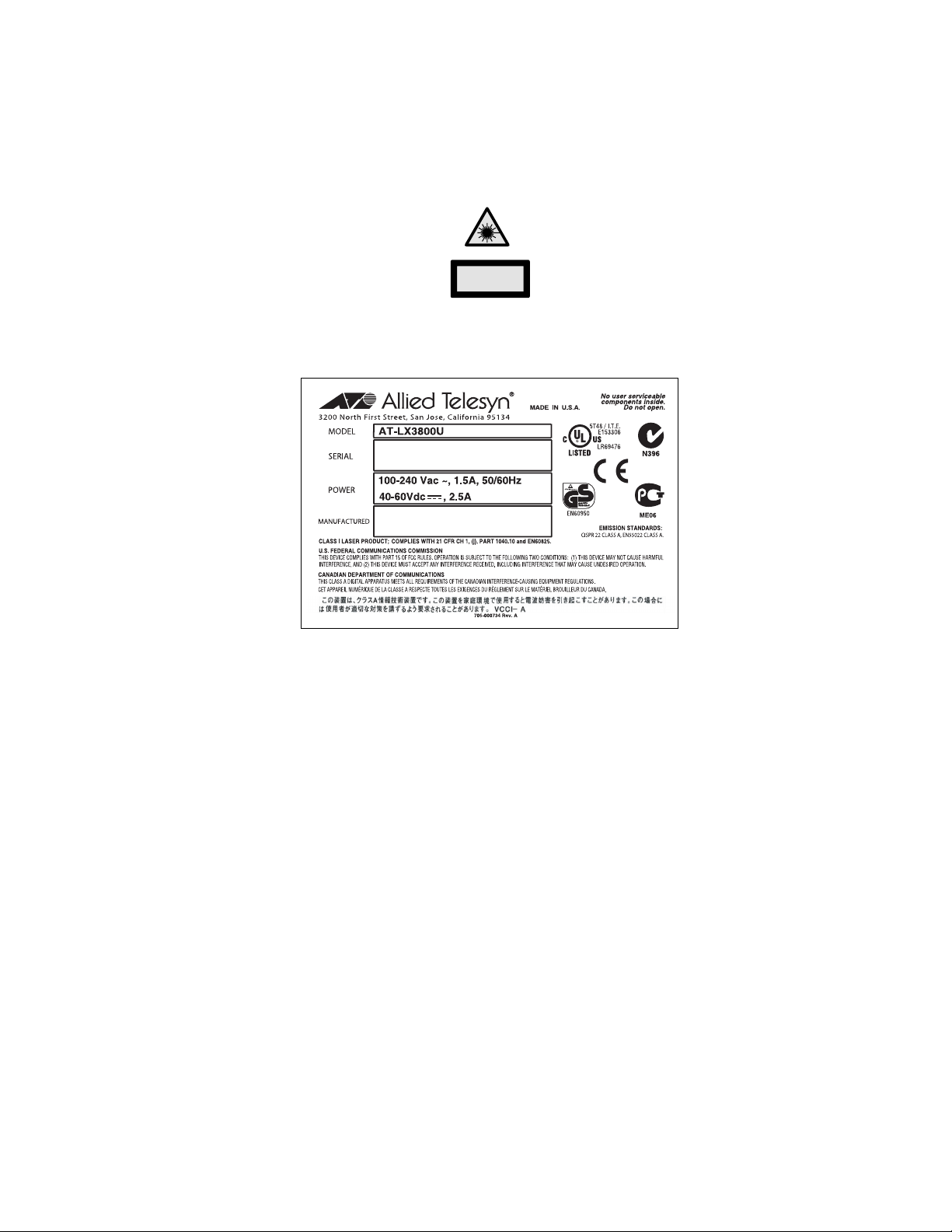
Product Labels
This label, located on the front panel of the unit, indicates the device is a Class 1 laser device.
CLASS 1
LASER PRODUCT
This label is located on the bottom panel of an AT-LX3800U Multi-Service Transport System.
5
Page 6

Translated Safety Statements
Important: Appendix C contains translated safety statements for installing this equipment. When
you see the , go to Appendix B for the translated safety statement in your language.
Wichtig: Anhang C enthält übersetzte Sicherheitshinweise für die Installation dieses Geräts. Wenn
Sie sehen, schlagen Sie in Anhang B den übersetzten Sicherheitshinweis in Ihrer Sprache nach.
Importante: El Apéndice C contiene mensajes de seguridad traducidos para la instalación de este
equipo. Cuando vea el símbolo , vaya al Apéndice B para ver el mensaje de seguridad traducido
a su idioma.
Important : L'annexe C contient les instructions de sécurité relatives à l'installation de cet
équipement. Lorsque vous voyez le symbole , reportez-vous à l'annexe B pour consulter la
traduction de ces instructions dans votre langue.
Importante: l’Appendice C contiene avvisi di sicurezza tradotti per l’installazione di questa
apparecchiatura. Il simbolo , indica di consultare l’Appendice B per l’avviso di sicurezza nella
propria lingua.
Важно: Приложение C содержит переведенную инструкцию по безопасности при установке
данного устройства. Если Вы встретите , перейдите к Приложению B для получения
переведенной инструкции по безопасности.
6
Page 7

Contents
Preface ................................................................................................................................................................................ 13
Safety Symbols Used in this Document................................................................................................................................ 14
Where to Find Web-based Guides ....................................................................................................................................... 15
Contacting Allied Telesyn ..................................................................................................................................................... 16
Online Support ..............................................................................................................................................................16
Email and Telephone Support....................................................................................................................................... 16
Returning Products........................................................................................................................................................16
Sales or Corporate Information .....................................................................................................................................16
Management Software Updates....................................................................................................................................16
Chapter 1: Overview ..........................................................................................................................................................17
System Description...............................................................................................................................................................18
Line Card Descriptions .........................................................................................................................................................20
AT-LX3801 Blank Slot Covers.............................................................................................................................................. 22
LEDs.....................................................................................................................................................................................23
Line Card LEDs ............................................................................................................................................................. 23
System LEDs.................................................................................................................................................................27
Management Connections....................................................................................................................................................29
Terminal Port................................................................................................................................................................. 29
10/100Base-TX Ethernet Port .......................................................................................................................................29
AT-LXPWR Power Supply Module .......................................................................................................................................30
AT-LXPWR/AC Power Supply.......................................................................................................................................30
AT-LXPWR/DC Power Supply.......................................................................................................
Power Connectors ................................................................................................................................................................32
AC Power Connector.....................................................................................................................................................32
DC Power Connector .................................................................................................................................................... 32
Topologies ............................................................................................................................................................................33
................................31
Chapter 2: Installation .......................................................................................................................................................37
Reviewing Safety Precautions..............................................................................................................................................38
Selecting a Site for the Chassis............................................................................................................................................42
TX and RX Fiber Optic Cable Specifications........................................................................................................................ 43
Unpacking the Chassis.........................................................................................................................................................44
Installing the Power Cord Retaining Clip (AC Power Supply Only) ......................................................................................45
Installing the AT-LX3800U Chassis in a Rack ......................................................................................................................47
Installing an AT-LX3811/x Line Card .................................................................................................................................... 50
Installing an SFP Transceiver in a Line Card .......................................................................................................................53
Installing an AT-LX3801 Blank Slot Cover............................................................................................................................ 55
Cabling the Chassis..............................................................................................................................................................57
Connecting the Fiber Optic Cables to a Line Card ........................................................................................................57
Connecting the Fiber Optic Cables to the TX and RX Ports..........................................................................................58
Powering On an AC Powered System..................................................................................................................................60
Wiring and Powering On a DC Powered System ................................................................................................................. 63
Starting a Local Management Session .................................................................................................................................66
Starting a Remote Management Session.............................................................................................................................68
Warranty Registration........................................................................................................................................................... 70
Chapter 3: Troubleshooting ..............................................................................................................................................71
PA or PB LED for the System is Off or Flashing...................................................................................................................71
RDY LED on a Line Card is Off ..................................................................................................
RDY LED on a Line Card is Flashing ................................................................................................................................... 72
..........................................72
7
Page 8

Contents
Line Card Tributary Side (SFP) RX and TX LEDs are Off ....................................................................................................72
Line Card Line Side RX and TX LEDs are Flashing Green or Off ........................................................................................73
Appendix A: Technical Specifications .............................................................................................................................75
Physical Specifications .........................................................................................................................................................75
Environmental Specifications................................................................................................................................................75
Power Specifications.............................................................................................................................................................75
Optical Specifications............................................................................................................................................................76
Safety and Electromagnetic Emissions Certifications...........................................................................................................77
Standards .............................................................................................................................................................................77
DIN-8 RS-232 Terminal Port Pinouts....................................................................................................................................77
10/100Base-TX Port Pinouts ................................................................................................................................................78
Appendix B: Cleaning Fiber Optic Connectors ...............................................................................................................79
Using a Cartridge-Type Cleaner ...........................................................................................................................................80
Using a Swab........................................................................................................................................................................82
Appendix C: Translated Safety Statements ....................................................................................................................85
8
Page 9

Figures
Figure 1. AT-LX3800U System Front Panel........................................................................................................................ 19
Figure 2. Back Panel of an AT-LX3800U System Ordered with an AC Power Supply Installed .........................................19
Figure 3. Back Panel of an AT-LX3800U System Ordered with a DC Power Supply Installed ........................................... 19
Figure 4. AT-LX3811/x Line Card........................................................................................................................................20
Figure 5. AT-LX3801 Blank Slot Cover................................................................................................................................22
Figure 6. Line Card LEDs ....................................................................................................................................................23
Figure 7. System LEDs........................................................................................................................................................27
Figure 8. AT-LXPWR/AC Power Supply..............................................................................................................................30
Figure 9. AT-LXPWR/DC Power Supply..............................................................................................................................31
Figure 10. AC Power Connector and On/Off Switch............................................................................................................ 32
Figure 11. DC Terminal Block.............................................................................................................................................. 32
Figure 12. Standard Point-to-Point Configuration................................................................................................................ 33
Figure 13. Regeneration Configuration Using the Internal Loopback Feature ....................................................................34
Figure 14. Loop-type Backbone Topology...........................................................................................................................35
Figure 15. Power Cord Retaining Clip .................................................................................................................................45
Figure 16. Power Cord Retaining Bracket ...........................................................................................................................45
Figure 17. Inserting the Retaining Clip into the Retaining Bracket ......................................................................................45
Figure 18. Retaining Clip Properly Installed in the Bracket .................................................................................................46
Figure 19. Removing Plastic Feet from the Chassis............................................................................................................47
Figure 20. Rack-Mount Bracket Configurations...................................................................................................................47
Figure 21. Mounting the AT-LX3800U Chassis in a 19-inch Rack ...................................................................................... 48
Figure 22. Removing the Dust Covers.................................................................................................................................50
Figure 23. Location of Alignment Guides.............................................................................................................................51
Figure 24. Inserting the Line Card.......................................................................................................................................51
Figure 25. Tightening the Captive Screws...........................................................................................................................52
Figure 26. Removing the Dust Plug from the SFP Port.......................................................................................................53
Figure 27. Installing an SFP Transceiver in a Line Card .......................................................................
Figure 28. Location of Alignment Guides.............................................................................................................................55
Figure 29. Installing the Blank Slot Cover............................................................................................................................56
Figure 30. Tightening the Captive Screws...........................................................................................................................56
Figure 31. Removing the Dust Plug from the SFP...............................................................................................................57
Figure 32. Connecting a Fiber Optic Cable to the SFP .......................................................................................................58
Figure 33. Removing the Dust Plugs from the TX and RX Ports.........................................................................................58
Figure 34. Connecting the TX and RX Cables..................................................................................................................... 59
Figure 35. On/Off Switch in Off Position..............................................................................................................................60
Figure 36. Power Cord Retaining Clip in the Up Position....................................................................................................60
Figure 37. Plugging in the AC Power Cord..........................................................................................................................61
Figure 38. Securing the Power Cord with the Retaining Clip...............................................................................................61
Figure 39. On/Off Switch in On Position..............................................................................................................................62
Figure 40. Positive, Frame Ground, and Negative Terminals..............................................................................................63
Figure 41. Wire Stripping Specification................................................................................................................................64
Figure 42. Connecting the Stripped Wire............................................................................................................................. 64
Figure 43. Connecting the Local Management Cable to the Terminal Port.........................................................................66
Figure 44. AT-S65 Main Menu............................................................................................................................................. 67
Figure 45. Connecting a Cable to the 10/100Base-T Port...................................................................................................68
Figure 46. DIN-8 RS-232 Connector and Port Pin Layouts.................................................................................................77
Figure 47. 10/100Base-TX Connector and Port Pinouts .....................................................................................................78
Figure 48. Ferrule in an SC Connector Plug........................................................................................................................79
Figure 49. Unclean and Clean Ferrule..........................................................................................
Figure 50. Cartridge Cleaner ...............................................................................................................................................80
..............................54
....................................... 79
9
Page 10

Figures
Figure 51. Rubbing the Ferrule Tip on the Cleaning Surface ..............................................................................................80
Figure 52. Lint-Free and Alcohol-Free Swabs .....................................................................................................................82
Figure 53. Cleaning a Recessed Ferrule.............................................................................................................................82
10
Page 11

Tables
Table 1. Safety Symbols .....................................................................................................................................................14
Table 2. AT-LX3811/x Line Cards ......................................................................................................................................20
Table 3. RDY LED ..............................................................................................................................................................23
Table 4. Tributary Side TX and RX LEDs ........................................................................................................................... 24
Table 5. Line Side TX and RX LEDs ..................................................................................................................................25
Table 6. Line Side Sync LED ..............................................................................................................................................27
Table 7. System LEDs ........................................................................................................................................................27
Table 8. Optical Power per Channel for Line Ports with Optical MUX/DEMUX Losses Included .......................................76
Table 9. Power Budget Per Channel ..................................................................................................................................76
Table 10. DIN-8 RS-232 Terminal Port Pinouts ..................................................................................................................77
Table 11. 10/100Base-TX Port Pinouts (MDIX Mode Only) ...............................................................................................78
11
Page 12

Tables
12
Page 13

Preface
This guide contains instructions on how to install an AT-LX3800U MultiService Transport System and contains the following sections:
“Safety Symbols Used in this Document” on page 14
“Where to Find Web-based Guides” on page 15
“Contacting Allied Telesyn” on page 16
13
Page 14
Preface
Safety Symbols Used in this Document
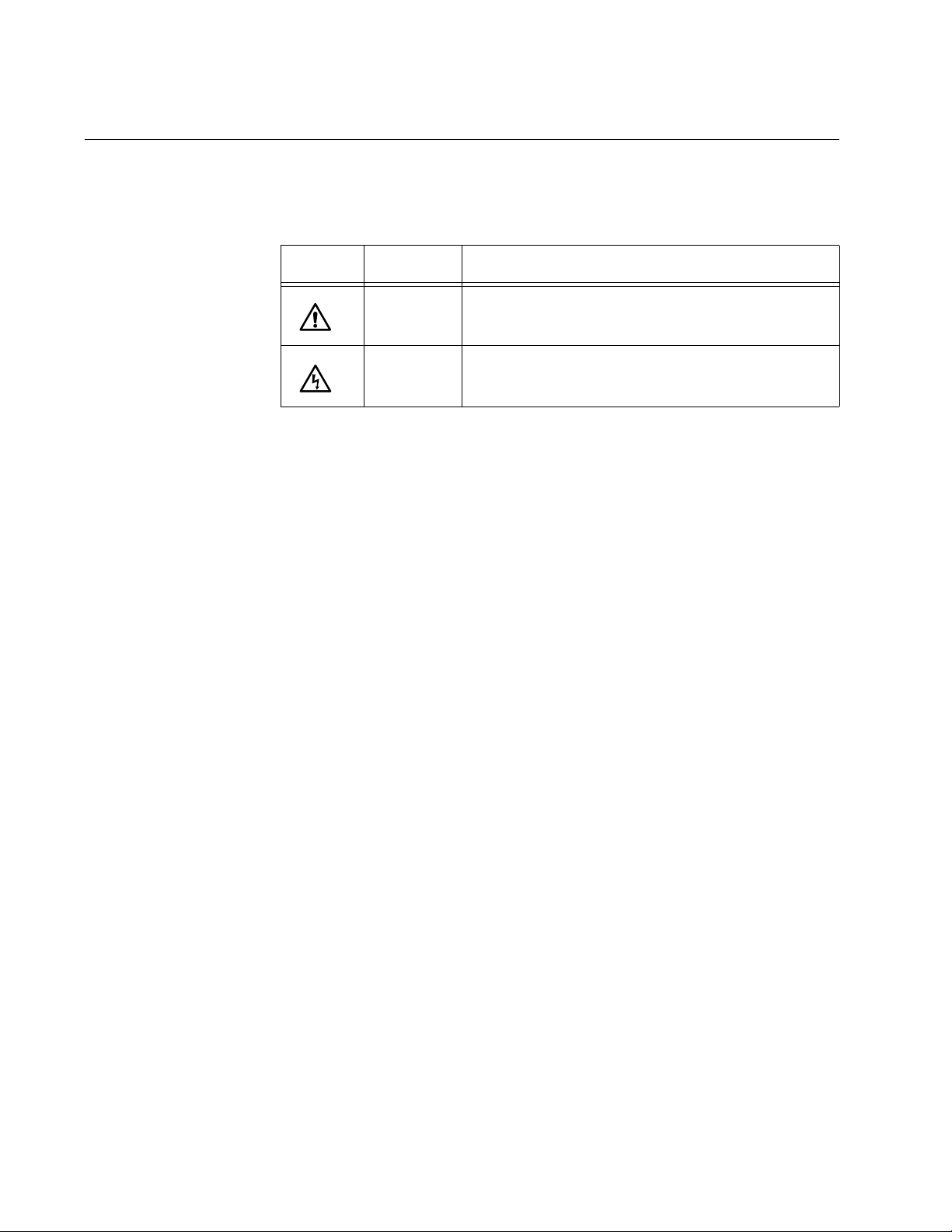
This document uses the safety symbols defined in Table 1.
Table 1. Safety Symbols
Symbol Meaning Description
Caution Performing or omitting a specific action may
result in equipment damage or loss of data.
Warning Performing or omitting a specific action may
result in electrical shock.
14
Page 15

AT-LX3800U Multi-Service Transport System Installation and Maintenance Guide
Where to Find Web-based Guides
The installation and user guides for all Allied Telesyn products are
available in portable document format (PDF) on our web site at
www.alliedtelesyn.com. You can view the documents online or download
them onto a local workstation or server.
15
Page 16

Preface
Contacting Allied Telesyn
This section provides Allied Telesyn contact information for technical
support as well as sales and corporate information.
Online Support You can request technical support online by accessing the Allied Telesyn
Knowledge Base: http://kb.alliedtelesyn.com. You can use the
Knowledge Base to submit questions to our technical support staff and
review answers to previously asked questions.
Email and
Telephone
Support
Returning
Products
Sales or
Corporate
Information
Management
Software Updates
For Technical Support via email or telephone, refer to the Support &
Services section of the Allied Telesyn web site: www.alliedtelesyn.com.
Products for return or repair must first be assigned a return materials
authorization (RMA) number. A product sent to Allied Telesyn without an
RMA number will be returned to the sender at the sender’s expense.
To obtain an RMA number, contact Allied Telesyn Technical Support
through our web site: www.alliedtelesyn.com.
You can contact Allied Telesyn for sales or corporate information through
our web site: www.alliedtelesyn.com. To find the contact information for
your country, select Contact Us -> Worldwide Contacts.
New releases of management software for our managed products are
available from either of the following Internet sites:
Allied Telesyn web site: www.alliedtelesyn.com
Allied Telesyn FTP server: ftp://ftp.alliedtelesyn.com
16
If you prefer to download new software from the Allied Telesyn FTP server
from your workstation’s command prompt, you will need FTP client
software and you must log in to the server. Enter “anonymous” for the user
name and your email address for the password.
Page 17

Chapter 1
Overview
The AT-LX3800U Multi-service Transport System aggregates up to eight
multi-rate services into a single fiber optic link using small form-factor
pluggable (SFP) transceivers.
This chapter contains the following sections:
“System Description” on page 18
“Line Card Descriptions” on page 20
“AT-LX3801 Blank Slot Covers” on page 22
“LEDs” on page 23
“Management Connections” on page 29
“AT-LXPWR Power Supply Module” on page 30
“Power Connectors” on page 32
“Topologies” on page 33
17
Page 18

Chapter 1: Overview
System Description
The AT-LX3800U Multi-service Transport System has the following
features:
An eight-slot chassis with integrated management module
One preinstalled AT-LXPWR/AC or AT-LXPWR/DC power supply in
the PWR A slot in the rear, with one expansion slot for an optional
redundant power supply unit. Both slots support any combination of
AC and DC power supplies.
Eight preinstalled AT-LX3801 Blank Slot Covers
Standard rack mounting or standalone
Eight AT-LX3811/x Multi-Service Line Cards available with industry
standard small form-factor pluggable (SFP) transceiver slots
Data rates from 100 MB to 2.5 GB
Numbered and color-coded system labels and line cards to eliminate
line card installation errors
Six LEDs per line card and four system LEDs
One RS-232 terminal port for local management
One 10/100Base-TX Ethernet port for remote management
Preinstalled AT-S65 management software for remote or local
management
The AT-LX3800U chassis is available with either an AC or a DC power
supply preinstalled.
18
Page 19

AT-LX3800U Multi-Service Transport System Installation and Maintenance Guide
Figure 1 shows the front panel of the AT-LX3800U system.
RS-232 Terminal Port
Line Card Slots
1 2 3 4 5 6 7 8
AT-LX3801 AT-LX3801 AT-LX3801 AT-LX3801 AT-LX3801 AT-LX3801AT-LX3801 AT-LX3801
10/100Base-T Port
Figure 1. AT-LX3800U System Front Panel
Figure 2 shows the back panel of an AC-powered system.
RX and TX Ports
AT-LX3800U
8
LASER PRODUCT
100 10
RESET
CLASS 1
10/100Base-TX
TX RX
LINE
TERMINAL
RS-232
122
FT
CO
PA
PB
AT-LXPWR/AC
AT-LXPWR/DC
AC Power Supply
FOR CENTRALIZED DC
POWER CONNECTION,
INSTALL ONLY IN A
RESTRICTED ACCESS
LOCATION
DC Power Supply
40-60VDC
ON
100-240VAC~
PWR A
PWR B
Figure 2. Back Panel of an AT-LX3800U System Ordered with an AC
Power Supply Installed
Figure 3 shows the back panel of a DC-powered system.
ON
PWR A
PWR B
Figure 3. Back Panel of an AT-LX3800U System Ordered with a DC
Power Supply Installed
470
704
19
Page 20

Chapter 1: Overview
Line Card Descriptions
The AT-LX3800U chassis can contain up to eight AT-LX3811/x line cards,
numbered and color-coded for insertion in the corresponding numbered
slot in the chassis, as described in Table 1.
Table 1. AT-LX3811/x Line Cards
Model Wavelength
AT-LX3811/1 1470 1
AT-LX3811/2 1490 2
AT-LX3811/3 1510 3
AT-LX3811/4 1530 4
AT-LX3811/5 1550 5
AT-LX3811/6 1570 6
AT-LX3811/7 1590 7
AT-LX3811/8 1610 8
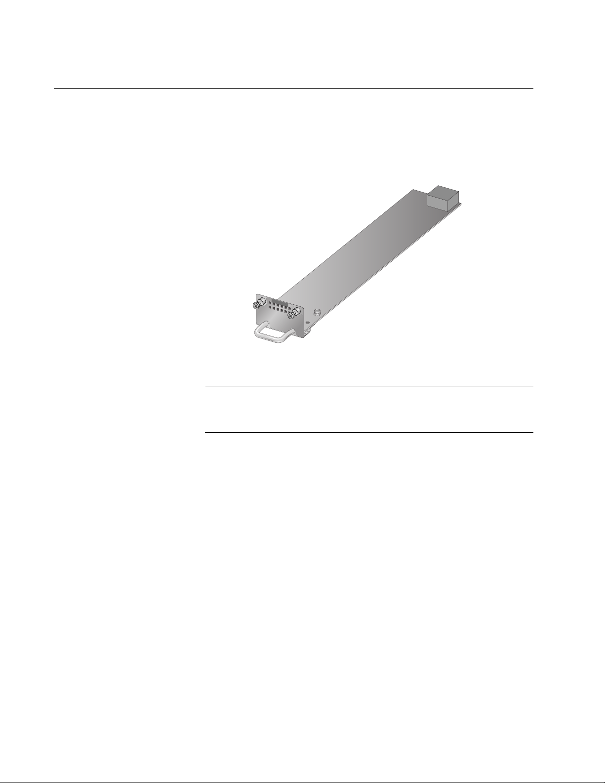
Figure 4 shows a sample AT-LX3811/x line card.
Slot
Number
20
AT-LX3811/8
RDY
TRIB
TX
RX
SYNC
TX
LINE
SFP
RX
123
Figure 4. AT-LX3811/x Line Card
Note
The RDY LED on the line card flashes and the AT-S65 management
software displays an error if a line card is inserted in the wrong slot.
Page 21

AT-LX3800U Multi-Service Transport System Installation and Maintenance Guide
The line cards are hot swappable into and out of the system. Each line
card can only be used in its dedicated slot.
Each AT-LX3811/x line card contains one SFP transceiver slot.
To install an AT-LX3811/x line card, refer to “Installing an AT-LX3811/x
Line Card” on page 50.
21
Page 22
Chapter 1: Overview
AT-LX3801 Blank Slot Covers
The AT-LX3800U chassis is shipped with eight AT-LX3801 Blank Slot
Covers in place. The blank slot cover protects the fiber optic connectors
on the backplane from becoming dirty, and helps maintain proper air flow
through the chassis. A blank slot cover is shown in Figure 5.
AT-LX3801
176
Figure 5. AT-LX3801 Blank Slot Cover
Note
Allied Telesyn strongly recommends that a blank slot cover be
inserted in any slot that does not contain a functioning line card.
To install a blank slot cover that was removed from the chassis, refer to
“Installing an AT-LX3801 Blank Slot Cover” on page 55.
22
Page 23
AT-LX3800U Multi-Service Transport System Installation and Maintenance Guide
SFP
SYNC
TX
RX
LINE
RDY
TX
RX
TRIB
LEDs
The AT-LX3800U provides two groups of LEDs, one group for each line
card and one group for the system.
Line Card LEDs Each line card has six LEDs, as shown in Figure 6.
Figure 6. Line Card LEDs
The line card LEDs include a RDY (Ready) LED that provides information
about the overall operation of the line card, and two groups marked TRIB
and LINE. The TRIB LEDs provide information about the tributary side of
the line card (the operation of the SFP), and the LINE LEDs display
information about the line side of the line card (the operation of the RX and
TX Wavelength Division Multiplexing (WDM) ports).
124
The LEDs are described in the following tables:
The RDY LED is described in Table 2.
The tributary side TX and RX LEDs are described in Table 3 on
page 24.
The line side TX and RX LEDs are described in Table 4 on page 25.
The line side Sync LED is described in Table 5 on page 27.
Table 2 describes the RDY LED on the tributary side.
Table 2. RDY LED
State Description
Flashing green Power is on, but the card is in the wrong slot.
Note that when a new version of the AT-S65
management software is being downloaded, the
RDY LED may flash on all line cards until the
downloading is complete.
Solid green Power is on and the card is in the correct slot.
Off The line card is not receiving any power.
23
Page 24

Chapter 1: Overview
Note
When you install or reinstall a line card, the AT-S65 management
software recognizes this change within 20 seconds.
The operation of the tributary side TX and RX LEDs is affected by the
status of the Missing Link feature in the AT-S65 management software.
Table 3 describes the TX and RX LEDs on the tributary side.
Table 3. Tributary Side TX and RX LEDs
Missing Link
State
TX and RX
State
Enabled TX: Solid green
RX: Solid green
TX: Off or
flashing green
RX: Solid green
TX: Flashing
green
RX: Off
Description
The SFP port has established a
link with its local end node as well
as with its corresponding end
node connected to the remote
system.
The SFP port is receiving packets
or a link signal from its local end
node but has not established a link
with its corresponding remote end
node connected to the remote
system.
Or, the port was manually disabled
using the AT-S65 software, but is
still receiving packets or a link
signal from its local end node.
The SFP port has not established
a link with its local end node. It is
receiving packets or a link signal
from its corresponding remote end
node connected to the remote
system.
24
TX: Off
RX: Off
No SFP is installed.
Or, the port was manually shut
down using the AT-S65
management software and the
local end node connected to the
port was powered off.
Or, the cable to the SFP port was
disconnected.
Page 25

AT-LX3800U Multi-Service Transport System Installation and Maintenance Guide
Table 3. Tributary Side TX and RX LEDs (Continued)
Missing Link
State
TX and RX
State
Disabled TX: Solid green
RX: Solid green
TX: Solid green
RX: Off
TX: Off
RX: Solid green
TX: Off
RX: Off
Description
The SFP port has established a
link with its end node.
The SFP port is transmitting
packets or a link signal but has not
established a link to its local end
node.
The port was manually shut down
using the AT-S65 management
software, but is still receiving
packets or a link signal from its
local end node.
No SFP is installed.
Or, the port was manually shut
down using the AT-S65
management software and the
end node connected to the port
was powered off.
Or, the cable to the SFP port was
disconnected.
The operation of the line side TX and RX LEDs is affected by the status of
the Missing Link feature in the AT-S65 management software. Table 4
describes the line side TX and RX LEDs.
Table 4. Line Side TX and RX LEDs
Missing Link
State
Enabled TX: Solid green
TX and RX
State
RX: Solid green
Description
The line port has established a link
with its corresponding end node
connected to the remote system.
TX: Off
RX: Off
The line port is not receiving or
sending packets.
Or, the port was manually shut
down using the AT-S65
management software while the
port was not receiving packets or a
signal.
25
Page 26

Chapter 1: Overview
Table 4. Line Side TX and RX LEDs (Continued)
Missing Link
State
TX and RX
State
Enabled TX: Flashing
green
RX: Off
TX: Off
RX: Flashing
green
Disabled TX: Solid green
RX: Solid green
TX: Flashing
green
RX: Off
Description
The line port has not established a
link with its corresponding end
node on the remote system and
the line port is not receiving
packets or a signal.
The local SFP port has not
established a link with its
corresponding local end node.
Or, the line port is not receiving
packets or a signal.
Or, the port was manually shut
down using the AT-S65
management software while the
port was receiving packets or a
signal.
The line port has established a link
with the remote line port.
The line port has not established a
link with the remote line port.
TX: Off
RX: Flashing
green
TX: Off
RX: Off
The port was manually shut down
using the AT-S65 management
software but is still receiving
packets or a link signal from its
remote end node.
The port was manually shut down
using the AT-S65 management
software.
Or, the optical cable to the remote
line port is disconnected.
26
Page 27

AT-LX3800U Multi-Service Transport System Installation and Maintenance Guide
CLASS 1
LASER PRODUCT
100 10
10/100Base-TX
RS-232
TERMINAL
FT
CO
PA
PB
RESET
Table 6 describes the line side Sync LED.
Table 5. Line Side Sync LED
State Description
Fast flashing green The RX path signal is synchronized.
Slow flashing green The TX path signal is synchronized.
Solid green Both the RX and TX path signals are
synchronized.
Off No activity.
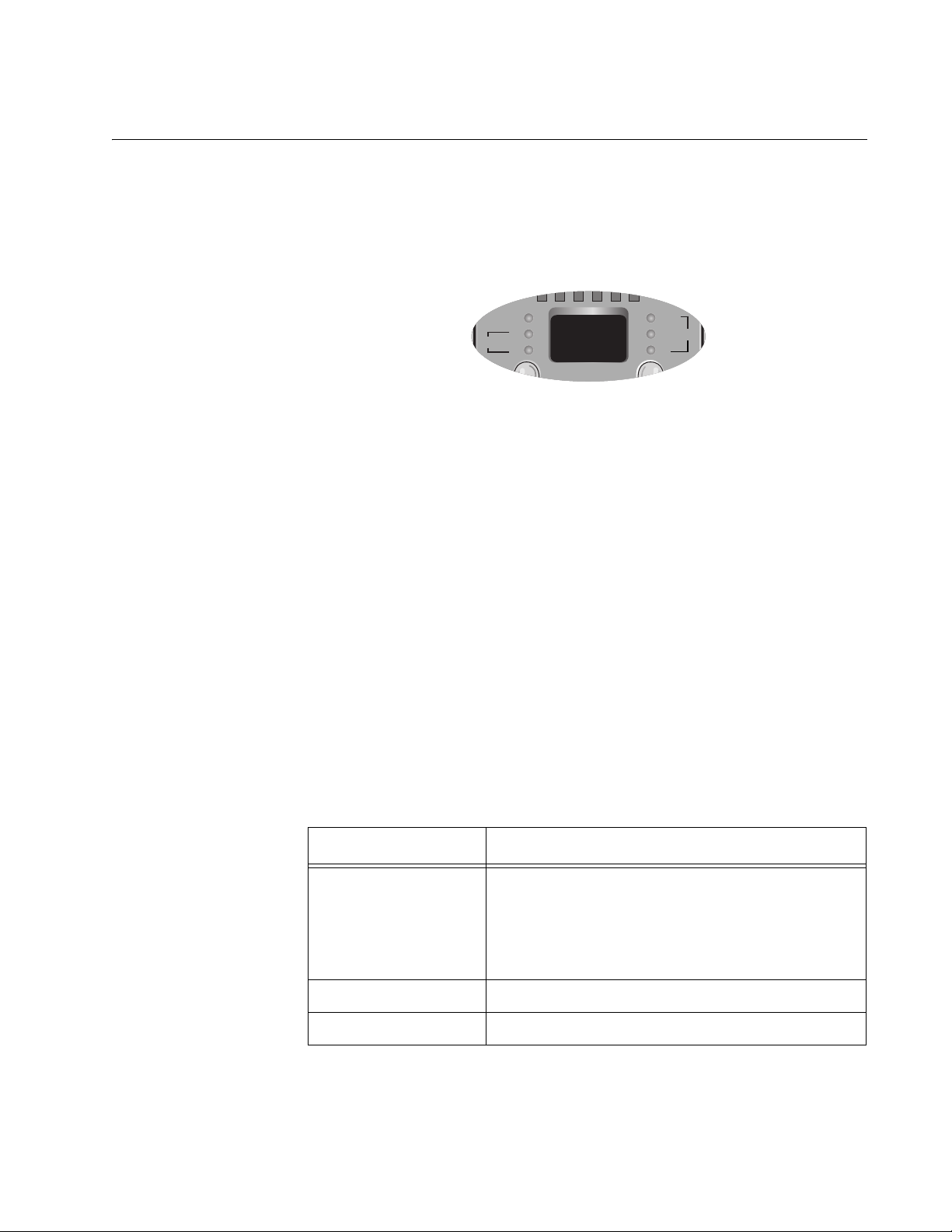
System LEDs To the right of the RS-232 terminal port are four system LEDs, as shown in
Figure 7 and described in Table 6.
125
Figure 7. System LEDs
Table 6. System LEDs
LED Definition State Description
FT Fault Solid red System fault.
CO Console Solid green User is logged in to the system
through the RS-232 terminal port.
Flashing green A management software update is
being downloaded through the
RS-232 terminal port.
PA Power supply
Solid green Normal operation.
slot A
Fast flashing green The output of the power supply in slot
A is not OK.
Slow flashing green The operation of the power supply in
slot A is normal but one or two fans
have failed.
27
Page 28

Chapter 1: Overview
LED Definition State Description
Table 6. System LEDs (Continued)
PB Power supply
slot B
Solid green Normal operation.
Fast flashing green The output of the power supply in slot
B is not OK.
Slow flashing green The operation of the power supply in
slot B is normal but one or two fans
have failed.
28
Page 29

AT-LX3800U Multi-Service Transport System Installation and Maintenance Guide
Management Connections
The AT-LX3800U chassis provides two management connections to the
preinstalled AT-S65 management software:
RS-232 terminal port for local (out-of-band) management
10/100Base-TX Ethernet port for remote management using Telnet
Terminal Port You can use the terminal port to establish a local (out-of-band)
management session with the chassis to configure parameters and also
view information about the operating of the system and line cards. You
establish a local management session with the switch by connecting either
a terminal, or a personal computer with a terminal emulation program, to
the port.
The terminal port has a DIN-8 style connector. A management cable is
supplied with the chassis.
10/100Base-TX
Ethernet Port
The terminal port is set to the following specifications:
Baud rate: 115200 bps
Data bits: 8
Parity: None
Stop bits: 1
You can use the AT-S65 management software to change the terminal
port settings.
You can also manage the AT-LX3800U chassis from any workstation on
your network through the 10/100Base-TX Ethernet port using Telnet.
29
Page 30

Chapter 1: Overview
AT-LXPWR Power Supply Module
The AT-LX3800U chassis is shipped with one AT-LXPWR power supply
preinstalled in slot A, and one empty slot (B) for an optional redundant
power supply (RPS). Two power supply versions, AC and DC, are
available for the AT-LX3800U chassis, as described below. Both slots
support any combination of AC and DC power supplies.
When two power supplies are installed, one of them works in standby
mode while the other one provides full power to the chassis. If one power
supply fails, the remaining power supply provides all the power to the
system, preventing a system failure.
AT-LXPWR/AC
Power Supply
The AT-LXPWR/AC power supply is shown in Figure 8.
AT-LXPWRAC
ON
100-240V
AC
~
126
Figure 8. AT-LXPWR/AC Power Supply
For information about installing an AT-LXPWR/AC power supply, consult
the documentation that is shipped with the unit.
30
Page 31

AT-LX3800U Multi-Service Transport System Installation and Maintenance Guide
AT-LXPWR/DC
Power Supply
The AT-LXPWR/DC power supply is shown in Figure 9.
AT-LXPWR/DC
FO
R
C
E
NT
R
P
A
O
LIZ
W
E
E
R
D
CO
D
C
N
N
IN
E
S
TA
L
L O
R
N
E
LY
S
TR
I
C
TED
A
LO
CA
TION
40-60VDC
CT
IO
N
,
IN
A
CCES
S
ON
700
Figure 9. AT-LXPWR/DC Power Supply
For information about installing an AT-LXPWR/DC power supply, consult
the documentation that is shipped with the unit.
31
Page 32

Chapter 1: Overview
ON
Power Connectors
The AT-LX3800U chassis is available with one of two power supply
options: AC or DC.
AC Power
Connector
DC Power
Connector
The AC power supply in an AT-LX3800U chassis has an On/Off switch, as
shown in Figure 10.
AT-LXPW
RAC
ON
100-240V
A
C
~
On/Off Switch
AC Power Connector
PWR A
471
Figure 10. AC Power Connector and On/Off Switch
The DC power supply in an AT-LX3800U chassis has a DC terminal block,
as shown in Figure 11.
32
706
Figure 11. DC Terminal Block
For information about wiring a DC power supply refer to “Wiring and
Powering On a DC Powered System” on page 63.
Page 33

Topologies
AT-LX3800U Multi-Service Transport System Installation and Maintenance Guide
The AT-LX3800U chassis can be configured for multiple network
topologies. The following figures show several possible configurations.
Figure 12 shows two AT-LX3800U systems linked to multiple devices.
Video
Server
Video
Server
Ethernet
Switch
Ethernet
Switch
Ethernet
Switch
AT-LX3800U
TX
RX
AT-LX3800U
Fibre
Channel
Fibre
Channel
ATM
Switch
Video
Server
RX
TX
Video
Server
Ethernet
Switch
Ethernet
Switch
Ethernet
Switch
Channel
Fibre
Channel
ATM
Switch
Fibre
Figure 12. Standard Point-to-Point Configuration
33
Page 34

Chapter 1: Overview
The AT-LX3800U system is capable of fully regenerating, retiming, and
reshaping each tributary service. This allows for configurations which
extend services beyond the limits of the point-to-point configuration, as
shown in Figure 13.
Site B
Regeneration Location
Site A
AT-LX3800U
TX
RX
RX
AT-LX3800U
TX
Site C
RX
AT-LX3800U
TX
TX
AT-LX3800U
RX
Figure 13. Regeneration Configuration Using the Internal Loopback
Feature
For more information about using the AT-S65 software to set up this type
of topology, refer to Chapter 5, “Line Card Modes of Operation” in the
AT-S65 Management Software User’s Guide.
34
Page 35

AT-LX3800U Multi-Service Transport System Installation and Maintenance Guide
Figure 14 illustrates a loop-type backbone topology.
Backbone
Switch
Switch
Backbone
AT-LX3800U AT-LX3800U
TX
RX
TX
RX
TX
RX
AT-LX3800U
RX
TX
AT-LX3800U
AT-LX3800U
TX
RX
AT-LX3800U
RX
TX
TX
RX
TX
RX
AT-LX3800UAT-LX3800U
Backbone
Switch
Backbone
Switch
Figure 14. Loop-type Backbone Topology
35
Page 36

Chapter 1: Overview
36
Page 37

Chapter 2
Installation
This chapter contains the following installation information for the
AT-LX3800U chassis:
“Reviewing Safety Precautions” on page 38
“Selecting a Site for the Chassis” on page 42
“TX and RX Fiber Optic Cable Specifications” on page 43
“Unpacking the Chassis” on page 44
“Installing the Power Cord Retaining Clip (AC Power Supply Only)” on
“Installing the AT-LX3800U Chassis in a Rack” on page 47
“Installing an AT-LX3811/x Line Card” on page 50
page 45
“Installing an SFP Transceiver in a Line Card” on page 53
“Installing an AT-LX3801 Blank Slot Cover” on page 55
“Cabling the Chassis” on page 57
“Powering On an AC Powered System” on page 60
“Wiring and Powering On a DC Powered System” on page 63
“Starting a Local Management Session” on page 66
“Starting a Remote Management Session” on page 68
“Warranty Registration” on page 70
37
Page 38
Chapter 2: Installation
Reviewing Safety Precautions
Please review the following safety precautions before you begin to install
the chassis or any of its components.
Note
When you see the
Safety, and Emission Information” on page 77 for translated safety
statements.
Warning: Class 1 Laser product.
Warning: Do not stare into the laser beam.
Warning: To prevent electric shock, do not remove the cover. No
user-serviceable parts inside. This unit contains hazardous
voltages and should only be opened by a trained and qualified
technician. To avoid the possibility of electric shock, disconnect
electric power to the product before connecting or disconnecting
the LAN cables.
, go to Appendix C, ”Translated Electrical,
1
2
3
Warning: Do not work on equipment or cables during periods of
lightning activity.
Warning: Power cord is used as a disconnection device. To deenergize equipment, disconnect the power cord.
Warning: Class I Equipment. This equipment must be earthed.
The power plug must be connected to a properly wired earth
ground socket outlet. An improperly wired socket outlet could
place hazardous voltages on accessible metal parts.
Pluggable Equipment. The socket outlet shall be installed near
the equipment and shall be easily accessible.
Caution: Air vents must not be blocked and must have free
access to the room ambient air for cooling.
Warning: Operating Temperature. This product is designed for a
maximum ambient temperature of 40° degrees C.
4
8
7
5
9
6
38
Page 39

AT-LX3800U Multi-Service Transport System Installation and Maintenance Guide
All Countries: Install product in accordance with local and
National Electrical Codes.
Warning: As a safety precaution, install a circuit breaker with a
minimum value of 15 Amps between the equipment and the DC
power source.
Always connect the wires to the LAN equipment first before you
connect the wires to the circuit breaker. Do not work with HOT
feeds to avoid the danger of physical injury from electrical shock.
Always be sure that the circuit breaker is in the OFF position
before connecting the wires to the breaker.
Warning: Do not strip more than the recommended amount of
wire. Stripping more than the recommended amount can create
a safety hazard by leaving exposed wire on the terminal block
after installation.
12
10
11
Warning: When installing this equipment, always ensure that the
frame ground connection is installed first and disconnected last.
13
Warning: Check to see if there are any exposed copper strands
coming from the installed wire. When this installation is done
correctly there should be no exposed copper wire strands
extending from the terminal block. Any exposed wiring can
conduct harmful levels of electricity to persons touching the
wires.
This system works with positive grounded or negative grounded
DC systems.
Circuit Overloading: Consideration should be given to the
connection of the equipment to the supply circuit and the effect
that overloading of circuits might have on overcurrent protection
and supply wiring. Appropriate consideration of equipment
nameplate ratings should be used when addressing this
concern.
14
23
15
39
Page 40

Chapter 2: Installation
Caution: Risk of explosion if battery is replaced by an incorrect
type. Replace only with the same or equivalent type
recommended by the manufacturer. Dispose of used batteries
according to the manufacturer’s instructions.
Attention: Le remplacement de la batterie par une batterie de
type incorrect peut provoquer un danger d’explosion. La
remplacer uniquement par une batterie du même type ou de
type équivalent recommandée par le constructeur. Les batteries
doivent être éliminées conformément aux instructions du
constructeur.
A tray cable is required to connect the power source if the unit is
powered by centralized DC power. The tray cable must be a UL
listed Type TC tray cable and rated at 600 V and 90 degrees C,
with three conductors, minimum 14 AWG.
Warning: Mounting of the equipment in the rack should be such
that a hazardous condition is not created due to uneven
mechanical loading.
24
27
26
Warning: This unit might have more than one power cord. To
reduce the risk of electric shock, disconnect all power cords
38
32
40
39
before servicing the unit.
If installed in a closed or multi-unit rack assembly, the operating
ambient temperature of the rack environment may be greater
than the room ambient temperature. Therefore, consideration
should be given to installing the equipment in an environment
compatible with the manufacturer’s maximum rated ambient
temperature (Tmra).
Caution: Installation of the equipment in a rack should be such
that the amount of air flow required for safe operation of the
equipment is not compromised.
Warning: Reliable earthing of rack-mounted equipment should
be maintained. Particular attention should be given to supply
connections other than direct connections to the branch circuits
(e.g., use of power strips).
Warning: Circuit breaker is used as a disconnection device. To
de-energize equipment, shut down the circuit breaker and then
disconnect the input wire.
40
Page 41

AT-LX3800U Multi-Service Transport System Installation and Maintenance Guide
Warning: This unit might have more than one power source. To
reduce the risk of electric shock, disconnect all power sources
before servicing the unit.
41
Page 42

Chapter 2: Installation
Selecting a Site for the Chassis
Observe the following requirements when you choose a site for the
chassis:
If you plan to install the chassis in an equipment rack, check to be sure
that the rack is safely secured and that it will not tip over. Devices in a
rack should be installed starting at the bottom, with the heavier devices
near the bottom of the rack.
If you are installing the chassis on a table, be sure that the table is
level and secure.
The power outlet for the chassis should be located near the unit and
should be easily accessible.
The site should provide easy access to the ports on the front of the
chassis. This arrangement will make it easy for you to connect and
disconnect cables as well as to view the LEDs.
To allow proper cooling of the chassis, air flow around the unit and
through its vents should be unrestricted.
Do not place objects on top of the chassis.
Do not expose the chassis to moisture or water.
Make sure that the site is a dust-free environment.
Use dedicated power circuits or power conditioners to supply reliable
electrical power to the device.
42
Page 43

AT-LX3800U Multi-Service Transport System Installation and Maintenance Guide
TX and RX Fiber Optic Cable Specifications
The TX and RX ports require 9µ single mode fiber (SMF) cable with a
simplex SC/UPC connector.
Note
For information about the fiber optic cabling specifications for the
line cards, refer to the SFP installation instructions.
43
Page 44

Chapter 2: Installation
Unpacking the Chassis
To unpack the chassis, perform the following procedure:
1. Remove all components from the shipping package.
2. Make sure that the following components are included in the package.
If any item is missing or damaged, contact your Allied Telesyn sales
representative for assistance.
One AT-LX3800U chassis with preinstalled Ac or DC power
Note
Store the packaging material in a safe location. You must use the
original shipping material if you need to return the unit to Allied
Telesyn.
supply
Two rack-mount brackets
Eight flathead Phillips rack-mount bracket screws
Power cord (AC models only; Americas, EU, Australia, and
UK only)
AC power cord retaining clip (AC models only)
Management cable with DIN-8 connector for local
management connection
Documentation CD
Warranty card
3. Place the AT-LX3800U chassis on a level, secure surface.
44
Page 45

AT-LX3800U Multi-Service Transport System Installation and Maintenance Guide
Installing the Power Cord Retaining Clip (AC Power Supply Only)
To install the power cord retaining clip on an AC powered system, perform
the following procedure:
1. Locate the power cord retaining clip, as shown in Figure 15.
Figure 15. Power Cord Retaining Clip
2. Locate the retaining bracket on each side of the AC power connector
on the back of the chassis, as shown in Figure 16.
AT-LXPWRAC
O
N
100-240VAC
~
PWR A
Bracket
473
Figure 16. Power Cord Retaining Bracket
3. With the “u” of the clip facing up, press the sides of the clip toward the
center and insert the short ends into the holes in the retaining bracket,
as shown in Figure 17.
AT-LXPWRAC
O
N
100-240VAC
~
PWR A
474
Figure 17. Inserting the Retaining Clip into the Retaining Bracket
45
Page 46

Chapter 2: Installation
4. Verify that the retaining clip is in the correct position, as shown in
Figure 18.
AT-LXPWRAC
O
N
100-240VAC
~
PWR A
Figure 18. Retaining Clip Properly Installed in the Bracket
46
Page 47

AT-LX3800U Multi-Service Transport System Installation and Maintenance Guide
Installing the AT-LX3800U Chassis in a Rack
The chassis is shipped with two rack-mount brackets. To mount the
chassis in a rack, perform the following procedure:
1. Place the chassis upside down on a level, secure surface.
2. Using a flathead screwdriver, remove the plastic feet from the bottom
of the chassis, as shown in Figure 19.
Figure 19. Removing Plastic Feet from the Chassis
3. Turn the chassis right side up.
4. Install a bracket on one side of the chassis using a Phillips screwdriver
and four of the rack-mount screws included with the unit. There are two
ways that you can attach the brackets to the chassis: so that it extends
forward from the rack, or flush with the front of the rack, as shown in
Figure 20.
136
801
8
8
8
AT-LX3800U
A
T-LX3801
C
L
A
S
L
S
A
S
1
E
R
P
R
O
D
U
C
T
100 10
RESET
10/100Base-TX
TX
LINE
RX
TERMINAL
FT
C
O
PA
RS-232
PB
8
AT-LX3800U
AT-LX380
1
TX
LINE
RX
C
L
A
S
L
S
A
S
1
E
R
P
R
O
D
U
C
T
100 10
TERMINAL
10/100Base-TX
FT
C
O
PA
RS-232
PB
RESET
Figure 20. Rack-Mount Bracket Configurations
5. Repeat step 4 to attach the remaining bracket to the other side of the
chassis.
47
Page 48

Chapter 2: Installation
7
6. Mount the chassis in a 19-inch rack using appropriate screws (not
supplied), as shown in Figure 21.
3801
AT-LX3801
8
8
AT-LX3800U
CL
ASS 1
LA
SE
R PRODUCT
100 10
RE
SET
10/100Base-TX
TX
LINE
RX
TERMINAL
F
T
C
O
P
A
RS-232
P
B
13
Figure 21. Mounting the AT-LX3800U Chassis in a 19-inch Rack
Warning: To prevent electric shock, do not remove the cover. No
user-serviceable parts inside. This unit contains hazardous
voltages and should only be opened by a trained and qualified
technician. To avoid the possibility of electric shock, disconnect
electric power to the product before connecting or disconnecting
the LAN cables.
3
Warning: Do not work on equipment or cables during periods of
lightning activity.
4
48
Warning: Power cord is used as a disconnection device. To de-
energize equipment, disconnect the power cord.
5
Warning: Class I Equipment. This equipment must be earthed.
The power plug must be connected to a properly wired earth
ground socket outlet. An improperly wired socket outlet could
place hazardous voltages on accessible metal parts.
6
Pluggable Equipment. The socket outlet shall be installed near
the equipment and shall be easily accessible.
7
Caution: Air vents must not be blocked and must have free
access to the room ambient air for cooling.
Warning: Operating Temperature. This product is designed for a
maximum ambient temperature of 40° degrees C.
8
9
Page 49

AT-LX3800U Multi-Service Transport System Installation and Maintenance Guide
Circuit Overloading: Consideration should be given to the
connection of the equipment to the supply circuit and the effect
that overloading of circuits might have on overcurrent protection
and supply wiring. Appropriate consideration of equipment
nameplate ratings should be used when addressing this
concern.
23
Warning: Mounting of the equipment in the rack should be such
that a hazardous condition is not created due to uneven
mechanical loading.
27
If installed in a closed or multi-unit rack assembly, the operating
ambient temperature of the rack environment may be greater
than the room ambient temperature. Therefore, consideration
should be given to installing the equipment in an environment
compatible with the manufacturer’s maximum rated ambient
temperature (Tmra).
38
Caution: Installation of the equipment in a rack should be such
that the amount of air flow required for safe operation of the
equipment is not compromised.
39
Warning: Reliable earthing of rack-mounted equipment should
be maintained. Particular attention should be given to supply
connections other than direct connections to the branch circuits
(e.g., use of power strips).
40
49
Page 50

Chapter 2: Installation
Installing an AT-LX3811/x Line Card
To install an AT-LX3811/x line card, perform the following procedure:
Note
The AT-LX3811 line cards are numbered and color-coded for
insertion in the corresponding numbered and color-coded slot in the
chassis. The RDY LED on the line card flashes green and the
AT-S65 management software displays an error if a line card is
inserted in the wrong slot.
1. Remove the AT-LX3811/x line card from its shipping package and
store the package in a safe place.
You must use the original package if you need to return the unit to
Allied Telesyn.
2. Select the slot in the AT-LX3800U chassis that corresponds to the
number of the line card you want to install.
3. Remove any AT-LX3801 Blank Slot Cover from the slot.
Keep the blank slot cover in a safe area in case you remove the line
card. The blank slot cover protects the fiber optic connectors on the
backplane from becoming dirty, and helps maintain proper air flow
through the chassis.
4. Remove the dust caps from the fiber optic connectors at the back of
the line card, as shown in Figure 22.
173
50
Figure 22. Removing the Dust Covers
Page 51

AT-LX3800U Multi-Service Transport System Installation and Maintenance Guide
RDY
TX
RX
TRIB
SYNC
TX
RX
LINE
3
4
5
6
S
FP
SYNC
TX
R
X
LINE
RDY
TX
RX
TRIB
AT-LX3811/3
SFP
SYNC
TX
RX
LINE
RDY
TX
RX
TRIB
AT-LX3811/4
TR
IB
R
TRIB
SYN
C
TX
RX
LINE
AT-LX3811/8
SFP
SYNC
TX
RX
LINE
RDY
TX
RX
TRIB
SFP
SYNC
TX
RX
LINE
RDY
TX
RX
TRIB
AT-LX3811/6
5. Locate the left and right alignment guides in the slot, as shown in
Figure 23.
Alignment Guides
138
Figure 23. Location of Alignment Guides
6. Align the back edge of the line card with the left and right alignment
guides.
7. Slide the line card into the slot that corresponds to the line card
number, as shown in Figure 24, until the faceplate is flush with the
front. (See “Line Card Descriptions” on page 20 for a list of the line
cards and their corresponding slot numbers.)
139
Figure 24. Inserting the Line Card
51
Page 52

Chapter 2: Installation
2
3
4
5
6
SFP
SYNC
TX
RX
LIN
E
R
DY
TX
RX
TRIB
AT-LX3811/3
SFP
SYNC
TX
R
X
LINE
R
DY
TX
RX
TR
IB
AT-LX3811/4
TRIB
RD
R
TR
IB
SYNC
TX
RX
LIN
E
SFP
S
YNC
TX
RX
LINE
R
DY
TX
R
X
TRIB
AT-LX3811/6
SFP
SYN
C
TX
R
X
LINE
R
DY
TX
R
X
TRIB
AT-LX3811/5
8. Use a Phillips head screwdriver to tighten the captive screws on the
line card, as shown in Figure 25.
140
Figure 25. Tightening the Captive Screws
Note
Always tighten the captive screws to secure the line card to the
chassis. This helps ensure that the fiber optic connectors at the back
of the line card are securely connected to the backplane.
9. Repeat this procedure to install additional line cards.
52
Page 53

AT-LX3800U Multi-Service Transport System Installation and Maintenance Guide
3
4
5
SFP
SYNC
TX
RX
LINE
RDY
TX
RX
TRIB
AT-LX3811/3
SFP
SYNC
TX
RX
LINE
RDY
TX
RX
TRIB
AT-LX3811/4
TRIB
SFP
SYNC
TX
RX
LINE
RDY
TX
RX
TRIB
AT-LX3811/5
Installing an SFP Transceiver in a Line Card
To install an SFP transceiver in a line card, perform the following
procedure:
Note
The transceiver can be hot swapped; you do not need to power off
the chassis to install an SFP transceiver. However, always remove
the cables before removing the SFP.
Note
You must install the transceiver before you connect cables to it.
1. Remove the SFP from its shipping container and store the packaging
material in a safe location.
Note
An SFP transceiver can be damaged by static electricity. Be sure to
observe all standard electrostatic discharge (ESD) precautions,
such as wearing an antistatic wrist strap, to avoid damaging the
transceiver.
2. Remove the dust plug from the SFP port, as shown in Figure 26.
Figure 26. Removing the Dust Plug from the SFP Port
Store the dust plug in a safe location for possible use later.
3. Locate the label on the transceiver and turn it so that the label is on the
top and the alignment groove is on the bottom.
53
Page 54

Chapter 2: Installation
3
4
5
S
FP
SYNC
TX
RX
LINE
RD
Y
TX
R
X
TRIB
AT-LX3811/3
SFP
SY
NC
TX
RX
LINE
RDY
TX
RX
TRIB
AT-LX3811/4
TRIB
SYNC
TX
RX
LINE
S
FP
S
YN
C
TX
R
X
LINE
RDY
TX
R
X
TRIB
AT-LX3811/5
RD
Y
TX
RX
TRIB
AT
4. Slide the SFP into the slot in the line card, as shown in Figure 27.
144
Figure 27. Installing an SFP Transceiver in a Line Card
For information about cabling the SFP, refer to “Connecting the Fiber
Optic Cables to a Line Card” on page 57.
54
Page 55

AT-LX3800U Multi-Service Transport System Installation and Maintenance Guide
RDY
TX
RX
TRIB
SYNC
TX
RX
LINE
Installing an AT-LX3801 Blank Slot Cover
The AT-LX3801 Blank Slot Cover protects the fiber optic connectors on
the backplane from becoming dirty, and helps maintain proper air flow
through the chassis.
Note
Allied Telesyn strongly recommends that a blank slot cover be
inserted in any slot that does not contain a functioning line card.
To install a blank slot cover, perform the following procedure:
1. Remove the AT-LX3801 Blank Slot Cover from its shipping package
and store the package in a safe place.
You must use the original package if you need to return the unit to
Allied Telesyn.
2. Select the slot in the AT-LX3800U chassis where you want to install
the blank slot cover.
3. If an AT-LX3811/x line card is installed in the slot, do the following:
a. Disconnect the cables from the SFP in the line card.
b. Reinstall the SFP port dust cap.
c. Remove the line card from the slot.
4. Locate the left and right alignment guides in the slot, as shown in
Figure 28.
Alignment Guides
138
Figure 28. Location of Alignment Guides
5. Align the back edge of the blank slot cover with the left and right
alignment guides.
55
Page 56

Chapter 2: Installation
3
4
5
6
S
FP
SYNC
TX
R
X
LIN
E
R
DY
TX
RX
TRIB
AT-LX3811/3
SFP
SYNC
TX
RX
LIN
E
RDY
TX
RX
TRIB
AT-LX3811/4
TR
IB
RD
R
TR
IB
FP
SY
NC
TX
RX
LIN
E
AT-LX3801
S
FP
SYNC
TX
R
X
LINE
RDY
TX
RX
TRIB
AT-LX3811/6
3
4
5
6
SFP
SYNC
TX
RX
LINE
R
DY
TX
RX
TRIB
AT-LX3811/3
SFP
SYNC
TX
R
X
LIN
E
RDY
TX
R
X
TRIB
AT-LX3811/4
TR
IB
R
TRIB
SYNC
TX
RX
LINE
SFP
SYNC
TX
RX
LINE
RDY
T
X
RX
TRIB
AT-LX3811/6
AT-LX3801
6. Slide the blank slot cover into the slot, as shown in Figure 29, until the
faceplate is flush with the front.
142
Figure 29. Installing the Blank Slot Cover
7. Use a Phillips head screwdriver to tighten the captive screws, as
shown in Figure 30.
Figure 30. Tightening the Captive Screws
Note
Always tighten the captive screws to secure the blank slot cover to
the chassis. This helps ensure that the fiber optic connectors on the
backplane are covered by the blank slot cover connectors.
8. Repeat this procedure to install additional blank slot covers.
56
Page 57

Cabling the Chassis
3
4
5
SFP
SYNC
TX
R
X
LINE
R
DY
TX
R
X
TRIB
AT-LX3811/3
S
FP
SYNC
TX
RX
LIN
E
R
DY
TX
R
X
TRIB
AT-LX3811/4
TRIB
SYNC
TX
R
X
LINE
SFP
SYNC
TX
RX
LINE
R
DY
TX
RX
TRIB
AT-LX3811/5
RDY
TX
RX
TR
IB
AT
Perform the following procedures to connect the fiber optic cables to the
tributary ports of the line cards and the line (WDM) ports of a device.
AT-LX3800U Multi-Service Transport System Installation and Maintenance Guide
Connecting the
Fiber Optic
Cables to a Line
Card
To connect a fiber optic cable to a line card, perform the following
procedure:
Warning: Class 1 Laser product.
Warning: Do not stare into the laser beam.
1
2
1. Remove the dust plug from the SFP in the line card, as shown in
Figure 27.
145
Figure 31. Removing the Dust Plug from the SFP
Note
For information about the proper cable type, refer to the installation
instructions you received with your SFP.
Note
Before you install the cable in SFP, verify that the optical power input
to the SFP is within the SFP transceiver’s dynamic range.
57
Page 58

Chapter 2: Installation
3
4
5
SFP
SYNC
TX
RX
LINE
RD
Y
TX
RX
TRIB
AT-LX3811/3
S
FP
SYNC
TX
RX
LINE
RDY
TX
RX
TRIB
AT-LX3811/4
TRIB
S
YNC
TX
RX
LINE
S
FP
SYNC
TX
R
X
LIN
E
RDY
TX
R
X
TRIB
AT-LX3811/5
RD
Y
TX
R
X
TRIB
A
2. Connect the fiber optic cable to the SFP, as shown in Figure 32.
146
Figure 32. Connecting a Fiber Optic Cable to the SFP
3. Repeat this procedure to cable additional line cards.
Connecting the
Fiber Optic
Cables to the TX
and RX Ports
To connect the fiber optic cables to the line ports, perform the following
procedure:
Warning: Class 1 Laser product. 1
Warning: Do not stare into the laser beam.
2
1. Remove the dust plugs from the TX and RX ports, as shown in
Figure 33.
8
8
AT-LX3800U
AT-LX3811/8
RDY
LINE
TX
TRIB
R
X
SYN
C
TX
SFP
R
X
LIN
E
TX
CLASS 1
LASER PRODUCT
100 10
R
E
S
E
T
10/100Base-TX
LINE
TERMINAL
RS-232
RX
FT
C
O
PA
P
B
147
Figure 33. Removing the Dust Plugs from the TX and RX Ports
Note
You must use 9µ single-mode fiber (SMF)
cable with a simplex SC/
UPC connector.
2. Measure the optical power coming into the RX port using a passthrough optical power monitor.
58
Page 59

AT-LX3800U Multi-Service Transport System Installation and Maintenance Guide
Note
A pass-through optical power monitor is required because when the
fiber optic cable is removed from the RX or TX port, the Open Fiber
Control algorithm is activated. This results in a significant reduction
in optical power compared to the closed loop actual optical power
value.
If the received optical power is greater than -7 dBm per channel,
additional attenuation is required. RX values greater than -7 dBm per
channel could potentially damage the optical receiver if applied for
more than 60 seconds.
Note
When you add attenuation to the system, ensure that the attenuated
value does not drop below the receiver’s sensitivity values. Refer to
“Optical Specifications” on page 76 for more information.
3. Remove the pass-through optical power monitor from the RX port.
4. Connect the appropriate fiber optic cable to the TX and RX line ports,
as shown in Figure 34.
8
8
AT-LX3800U
AT-LX3811/8
RDY
LINE
TX
TRIB
RX
SYNC
TX
SFP
RX
LINE
R
TX
CLASS 1
LASER PRODUCT
100 10
E
S
E
T
10/100Base-TX
LINE
TERMINAL
RS-232
RX
FT
CO
PA
PB
148
Figure 34. Connecting the TX and RX Cables
59
Page 60

Chapter 2: Installation
Powering On an AC Powered System
To power on an AC powered chassis, perform the following procedure:
1. Make sure that the on/off switch is in the Off position, as shown in
Figure 35.
AT-LXPWRAC
Figure 35. On/Off Switch in Off Position
O
N
100-240VAC
~
PWR A
2. Position the power cord retaining clip in the up position, as shown in
Figure 36.
AT-LXPWRAC
O
N
100-240VAC
~
PWR A
Figure 36. Power Cord Retaining Clip in the Up Position
60
Page 61

AT-LX3800U Multi-Service Transport System Installation and Maintenance Guide
3. Plug the power cord into the AC power connector on the back of the
chassis, as shown in Figure 37.
AT-LXPWRAC
O
N
100-240VAC
~
PWR A
477
Figure 37. Plugging in the AC Power Cord
4. Secure the cord by lowering the power cord retaining clip, as shown in
Figure 38.
AT-LXPWRAC
O
N
100-240VA
C
~
Figure 38. Securing the Power Cord with the Retaining Clip
5. Plug the other end of the power cord into a wall outlet.
PWR A
478
61
Page 62

Chapter 2: Installation
6. Move the On/Off power switch to the On position, as shown in
Figure 39.
AT-LXPWRAC
O
N
100-240VAC
~
PWR A
Figure 39. On/Off Switch in On Position
7. When power is applied, the chassis begins to load the AT-S65
software.
Warning: Power cord is used as a disconnection device. To deenergize equipment, disconnect the power cord.
5
Class I Equipment. This equipment must be earthed. The power
plug must be connected to a properly wired earth ground socket
outlet. An improperly wired socket outlet could place hazardous
voltages on accessible metal parts.
6
Pluggable Equipment. The socket outlet shall be installed near
the equipment and shall be easily accessible.
7
Warning: This unit might have more than one power cord. To
reduce the risk of electric shock, disconnect all power cords
before servicing the unit.
32
The chassis is now ready for network operations.
No further installation steps are required if you do not need to change the
default parameter settings of the chassis, which are listed in the AT-S65
Management Software User’s Guide. However, if you want to manage the
chassis or review the settings, refer to “Starting a Local Management
Session” on page 66 and “Starting a Remote Management Session” on
page 68.
62
Page 63

AT-LX3800U Multi-Service Transport System Installation and Maintenance Guide
Wiring and Powering On a DC Powered System
For a DC powered system, perform the following steps:
1. Before you attach wires to the DC terminal block on the DC power
supply, review the following warning:
Warning: As a safety precaution, install a circuit breaker with a
minimum value of 15 Amps between the equipment and the DC
power source.
Always connect the wires to the LAN equipment first before you
connect the wires to the circuit breaker. Do not work with HOT
feeds to avoid the danger of physical injury from electrical
shock. Always be sure that the circuit breaker is in the OFF
position before connecting the wires to the breaker.
A tray cable is required to connect the power source if the unit
is powered by centralized DC power. The tray cable must be a
UL listed Type TC tray cable and rated at 600 V and 90
degrees C, with three conductors, minimum 14 AWG.
11
26
2. On the rear side of the DC power supply is a DC terminal block.
Starting from the left side of the terminal block, identify the positive,
frame ground, and negative terminals using the diagram adjacent to
the terminal block as shown in Figure 40.
40-60VDC
FOR CENTRALIZED DC
POWER CONNECTION,
INSTALL ONLY IN A
RESTRICTED ACCESS
LOCATION
Positive
703
Frame Ground
Negative
Figure 40. Positive, Frame Ground, and Negative Terminals
63
Page 64

Chapter 2: Installation
3. With a 14-gauge wire-stripping tool, strip the three wires in the tray
cable coming from the DC input power source to 8mm ± 1mm (0.31 in.,
± 0.039 in.).
Warning: Do not strip more than the recommended amount of
wire. Stripping more than the recommended amount can create
a safety hazard by leaving exposed wire on the terminal block
after installation.
8mm ±1mm
(0.31in. ±0.039 in.)
12
Figure 41. Wire Stripping Specification
4. Connect the frame ground wire to the terminal marked with the
ground symbol by inserting the wire into the terminal and tightening the
connection with a flathead screwdriver, as shown in Figure 42.
Warning: When installing this equipment, always ensure that
the frame ground connection is installed first and disconnected
last.
13
705
Figure 42. Connecting the Stripped Wire
5. Connect the positive feed wire to the terminal block marked (+).
64
Page 65

AT-LX3800U Multi-Service Transport System Installation and Maintenance Guide
6. Connect the negative feed wire to the terminal block marked (-).
Warning: Check to see if there are any exposed copper
strands coming from the installed wire. When this installation is
done correctly there should be no exposed copper wire strands
extending from the terminal block. Any exposed wiring can
conduct harmful levels of electricity to persons touching the
wires.
14
7. Secure the tray cable near the rack framework using multiple cable ties
to minimize the chance of the connections being disturbed by casual
contact with the wiring. Use at least four cable ties separated four
inches apart with the first one located within six inches of the terminal
block.
This system works with positive grounded or negative
grounded DC systems.
15
8. Ensure that the circuit breaker is in the Off position.
9. Connect the DC wires to the circuit breaker. (Refer to “Power
Specifications” on page 75 for the power requirements.)
10. Power on the circuit breaker.
11. Verify that the PB (PWR B) LED on the front unit is green. If the PB
LED is off or if the FT (FAULT) LED is solid red, refer to Chapter 3,
“Troubleshooting” on page 71.
When power is applied, the switch begins to load the AT-S65 software.
The loading process takes approximately 20 to 30 seconds to
complete.
Warning: Circuit breaker is used as a disconnection device. To
de-energize equipment, shut down the circuit breaker and then
disconnect the input wire.
Warning: This unit might have more than one power source. To
reduce the risk of electric shock, disconnect all power sources
before servicing the unit.
65
Page 66

Chapter 2: Installation
Starting a Local Management Session
The procedure in this section explains how to start a local (out-of-band)
management session using the RS-232 terminal port on the chassis. You
can use a local management session to configure the chassis operating
parameters and view system status using the AT-S65 management
software.
Note
Only one manager can log in at a time.
To start a local management session, perform the following procedure:
1. Connect the DIN-8 end of the management cable included with the
AT-LX3800U chassis to the RS-232 terminal port on the front of the
chassis, as shown in Figure 43.
8
8
AT-LX3800U
AT-LX3811/8
RDY
LINE
TX
TRIB
RX
SYNC
TX
LINE
SFP
RX
154
TX
CLASS 1
LASER PRODUCT
100 10
RESET
10/100Base-TX
LINE
TERMINAL
RS-232
RX
FT
C
O
PA
P
B
154
Figure 43. Connecting the Local Management Cable to the Terminal Port
2. Connect the other end of the cable to an RS-232 port on a terminal or
PC with a terminal emulation program.
3. Configure the terminal or terminal emulation program to the following
settings:
Baud rate: 115200 bps
Data bits: 8
Parity: None
66
Stop bits: 1
Flow control: None
Page 67

AT-LX3800U Multi-Service Transport System Installation and Maintenance Guide
Note
These settings are for a DEC VT100 or ANSI terminal, or an
equivalent terminal emulation program.
The software initializes.
4. Press Return.
The Login prompt is displayed.
5. To configure chassis settings, enter “manager” as the user name. To
only view the settings, enter “operator” as the user name.
The Password prompt is displayed.
6. To configure chassis settings, enter “friend” as the password for a
manager login. To only view the settings, enter “operator” as the
password for an operator login.
The Main Menu is displayed, as shown in Figure 44
Allied Telesyn AT-LX3800
LX3800
Main Menu
Module Status and Configuration
Administration
System Configuration
Quit
Figure 44. AT-S65 Main Menu
Refer to the AT-S65 Management Software User’s Guide for information
about how to move through the menus and make menu selections.
67
Page 68

Chapter 2: Installation
5
Starting a Remote Management Session
The procedure in this section explains how to start a remote management
session using the 10/100Base-TX port on the chassis. You can use a
remote management session to configure the chassis operating
parameters and view system status using the AT-S65 management
software.
To manage a chassis remotely, you must first assign an IP address to it.
For information about assigning an IP address to the system, refer to
Chapter 1, “Getting Started,” in the AT-S65 Management Software User’s
Guide.
To start a remote management session, perform the following procedure:
1. Connect a twisted pair cable to the 10/100Base-T port on the front of
the chassis, as shown in Figure 45.
8
8
AT-LX3800U
AT-LX3811/8
RDY
LINE
TX
TRIB
RX
SYNC
TX
LINE
SFP
RX
TX
CL
ASS 1
LAS
ER P
RO
DU
C
T
100 10
R
ESE
T
10/100Base-TX
LINE
TERMINAL
RS-232
RX
FT
CO
PA
PB
15
Figure 45. Connecting a Cable to the 10/100Base-T Port
Note
The RJ-45 port runs in MDIX mode. Be sure to use the proper cable.
The connector and port pinouts are shown in “10/100Base-TX Port
Pinouts” on page 78.
2. In the Telnet application, specify the IP address of the AT-LX3800U
chassis that you want to access.
The software initializes and then the Login prompt is displayed.
68
3. To configure chassis settings, enter “manager” as the user name. To
only view the settings, enter “operator” as the user name.
The Password prompt is displayed.
Page 69

AT-LX3800U Multi-Service Transport System Installation and Maintenance Guide
4. To configure chassis settings, enter “friend” as the password for a
manager login. To only view the settings, enter “operator” as the
password for an operator login.
The Main Menu is displayed, as shown in Figure 40 on page 30.
Refer to the AT-S65 Management Software User’s Guide for information
about how to move through the menus and make menu selections.
69
Page 70

Chapter 2: Installation
Warranty Registration
When you have finished installing the system, you should register your
product by completing and mailing the enclosed warranty card.
70
Page 71

Chapter 3
Troubleshooting
This chapter contains information about how to troubleshoot the chassis
and line cards in the event that a problem occurs.
Note
If after following the instructions in this chapter you are unable to
resolve the problem, contact Allied Telesyn Technical Support for
assistance. Refer to “Contacting Allied Telesyn” on page 16 for
contact information.
PA or PB LED for the System is Off or Flashing
The chassis must have at least one operational power supply, indicated by
the PA (power supply A) and PB (power supply B) LEDs.
If all LEDs, including those on the chassis and line cards, are off, do one or
all of the following:
Verify that the On/Off switch for that power supply is turned to On.
Replace the AC power cord.
Verify that the power supply is completely installed in its slot.
If one of the power supply LEDs is off, but the other LED is on, do the
following:
Verify that the power supply in question is completely installed in its
slot.
If one or both of the power supply LEDs are slowly flashing, do the
following:
Verify that the On/Off switch for that power supply is turned to On.
Verify that the power cord is secured in the connector.
If one or both of the power supply LEDs are quickly flashing, verify that the
fans are still operational.
71
Page 72

Chapter 3: Troubleshooting
RDY LED on a Line Card is Off
If the RDY LED on a line card is off, do the following:
Verify that at least one power supply is operational.
Verify that the On/Off switch at the back of the system is turned to On.
Verify that the AT-LX3811/x line card is firmly inserted in the slot.
For more information about the RDY LED, refer to Table 2, ”RDY LED” on
page 23.
RDY LED on a Line Card is Flashing
If the RDY LED on a line card is flashing, do the following:
Verify that the line card is in the correct slot: the color and number of
the line card should match the color and number of the slot. If the line
card is not in the correct slot, move it to the correct slot.
Remove and reinsert the line card.
Line Card Tributary Side (SFP) RX and TX LEDs are Off
If one or both of the TX and RX LEDs on the tributary (SFP) side of the line
card are off, do the following:
Verify that the device connected to the SFP is powered on.
Verify that the corresponding remote end node connected to the
remote system is powered on.
Verify that the SFP is firmly seated in the SFP slot.
Verify that the fiber optic cable is securely connected to the SFP and to
the port on the end device.
Verify that you are using the appropriate type of fiber optic cable. Refer
to the SFP installation guide for cabling specifications.
Clean the fiber optic connectors following the instructions in Appendix
B, ”Cleaning Fiber Optic Connectors” on page 79.
If the SFP has a dual LC connector, verify that the fiber strand
connected to the RX port is connected to the TX port on the remote
end device, and that the fiber strand connected to the RX port is
connected to the TX port.
72
For additional information about these LEDs, refer to Table 3, ”Tributary
Side TX and RX LEDs” on page 24.
Page 73

AT-LX3800U Multi-Service Transport System Installation and Maintenance Guide
Line Card Line Side RX and TX LEDs are Flashing Green or Off
If one or both of the TX or RX LEDs for the LINE side of the line card is
flashing green continuously or off, do the following:
Verify that all fiber optic cables are securely connected to the RX and
TX ports.
Verify that the local TX port is connected to the RX port on the remote
system and that the local RX port is connected to the TX port on
remote system. The systems will not pass data if two TX or two RX
ports are interconnected.
Verify that the end nodes connected to the local and remote systems
are powered on.
Clean the fiber optic connectors following the instructions in Appendix
B, ”Cleaning Fiber Optic Connectors” on page 79.
Use a fiber optic tester (pass-through optical monitor) to verify that the
link attenuation is less than 35 dB.
For additional information about these LEDs, refer to Table 4, ”Line Side
TX and RX LEDs” on page 25.
73
Page 74

Chapter 3: Troubleshooting
74
Page 75

Appendix A
Technical Specifications
Physical Specifications
Dimensions: 4.45 cm x 43.18 cm x 45.72 cm
Weight: 18 lbs.
Recommended Minimum Ventilation
on All Sides 10 cm (4.0 in)
(1.75 in. x 17.0 in. x 18.0 in.)
(H x W x D)
Environmental Specifications
Operating Temperature: 0° C to 40° C (32° F to 104° F)
Storage Temperature: -25° C to 70° C (-13°F to 158° F)
Operating Humidity: 5% to 90% non-condensing
Storage Humidity: 5% to 95% non-condensing
Maximum Operating Altitude: 4,000 m (13,000 ft.)
Maximum Storage Altitude: 4,000 m (13,000 ft.)
Power Specifications
AC Version
Maximum Power Consumption: 120 watts AC
Input Voltage 100 - 240 VAC
Maximum Input Current 1.5 A
75
Page 76

Appendix A: Technical Specifications
DC Version
Maximum Power Consumption: 100 watts
Input Voltage 40 - 60 VDC
Maximum Input Current 2.5 A
Optical Specifications
Table 7. Optical Power per Channel for Line Ports with Optical MUX/DEMUX Losses Included
Slot
No.
1 1470 1 4 -25 -28 -30 -32
2 1490 1 4 -25 -28 -30 -32
3 1510 0 3 -26 -29 -31 -33
4 1530 0 3 -26 -29 -31 -33
5 1550 0 3 -26 -29 -31 -33
6 1570 -1 2 -27 -30 -32 -34
7 1590 -1 2 -27 -30 -32 -34
8 1610 -1 2 -27 -30 -32 -34
Wavelength
(nm)
TX Line Port
Output**
Power, dBm
Min. Max.
* The Rx port’s maximum input signal is -7 dBm
** Closed Fiber Link (otherwise, OFC [open fiber control] will reduce the
output power)
RX Line Port
Sensitivity*
OC-48, dBm
BER=10^-10
RX Line Port
Sensitivity*
GE,dBm
BER=10^-12
RX Line Port
Sensitivity*
OC-12, dBm
BER=10^-10
RX Line Port
Sensitivity*
OC-3, dBm
BER=10^-10
Table 8. Power Budget Per Channel
LX3800U OC-48 GbE OC-12 OC-3 Fast Ethernet
Power budget
(MUX/DEMUX
included)
Dispersion
penalty for fiber
with 20ps/
(nm*km) at 1610
nm
76
26 dB
BER<10^-10
<3 dB
(80 km)
29 dB
BER<10^-12
<1dB
(135 km)
31 dB
BER<10^-10
<1dB
(135 km)
33 dB
BER<10^-10
<1 dB
(135 km)
33 dB
BER<10^-12
<1 dB
(135 km)
Page 77

AT-LX3800U Multi-Service Transport System Installation and Maintenance Guide
Safety and Electromagnetic Emissions Certifications
EMI: FCC Part 15 Class A, EN 5502 Class A,
CISPR Class A, VCCI Class A, C-TICK, CE
Immunity: EN 55024
Safety: UL 609950 (
Quality and Reliability: MTBF > 100,000 hrs.
Standards
IEEE 802.3 (10Base-T)
IEEE 802.3u (100Base-TX)
DIN-8 RS-232 Terminal Port Pinouts
Figure 46 illustrates the pin layout of the DIN-8 RS-232 terminal port
connector and port.
678
34 5
12
158
7
8
5
21
CULUS
), EN 60950
6
3
4
Figure 46. DIN-8 RS-232 Connector and Port Pin Layouts
Table 9 lists the definitions for the DIN-8 RS-232 terminal port pinouts.
Table 9. DIN-8 RS-232 Terminal Port Pinouts
Pin Signal
1NC
2DTR
3TX
4RX
5DSR
6GND
77
Page 78

Appendix A: Technical Specifications
Table 9. DIN-8 RS-232 Terminal Port Pinouts (Continued)
10/100Base-TX Port Pinouts
Figure 47 illustrates the pin layout of the 10/100Base-TX connector and
port.
Pin Signal
7RTS
8CTS
8
1
8
1
Figure 47. 10/100Base-TX Connector and Port Pinouts
Table 10 lists the definitions for the 10/100Base-TX connector and port
pins.
Table 10. 10/100Base-TX Port Pinouts (MDIX Mode Only)
Pin Signal
1RD+
2RD-
3TD+
4NC
5NC
6TD-
7NC
8NC
78
Page 79

Appendix B
Cleaning Fiber Optic Connectors
The fiber optic connector consists of a fiber optic plug and its adapter. The
end of the fiber optic cable is held in the core of the ferrule in the plug.
Light signals are transmitted through the core of the fiber. Even minor
smudges or dirt on the end face of the fiber, completely invisible to the
naked eye, can disrupt light transmission and lead to failure of the
component or of the entire system. Therefore, it is of utmost importance to
clean all fiber optic connectors before use.
Figure 48 shows the ferrule in an SC connector.
177
Ferrule
Figure 48. Ferrule in an SC Connector Plug
Figure 49 shows part of the end face of an unclean and clean ferrule.
156
Unclean Clean
Figure 49. Unclean and Clean Ferrule
This appendix provides the following procedures
“Using a Cartridge-Type Cleaner” on page 80
“Using a Swab” on page 82
79
Page 80

Appendix B: Cleaning Fiber Optic Connectors
Using a Cartridge-Type Cleaner
Fiber optic cartridge cleaners are available from many vendors and are
typically called “cartridge cleaners,” as shown in Figure 50.
n
tio
c
ing
ire
ip
D
W
TAPE A
PUSH OPENPUSH OPEN
Figure 50. Cartridge Cleaner
Note
Do not use compressed air or aerosol air to clean a fiber optic
connector.
To clean a fiber optic connector using a cartridge cleaner, perform the
following procedure.
5. With one hand, hold the cartridge cleaner and push the lever on the
cleaning cartridge in the direction of the arrow to expose the cleaning
surface, as shown in Figure 51.
6. Place the ferrule tip on the exposed cleaning surface and rub the
ferrule in a downward direction, as shown in Figure 51.
80
Figure 51. Rubbing the Ferrule Tip on the Cleaning Surface
Page 81

AT-LX3800U Multi-Service Transport System Installation and Maintenance Guide
Note
Rub the ferrule tip on the cleaning surface in one direction only.
7. When you reach the end of the cleaning surface, pick up the ferrule tip,
rotate and place it at the top and rub downwards at least 2 times.
Caution
Failing to pick up the ferrule tip when you reach the bottom of the
cleaning surface can result in static electricity that can damage the
fiber optic cable.
8. If desired, repeat steps 3 and 4.
9. If a fiber inspection scope is available, use the scope to inspect the
ferrule end face to make sure that it is clean.
10. Reconnect the cable to the port or protect the ferrule tip with a dust
cap.
Note
Always keep a dust cap on a fiber optic cable when it is not in use.
Note
Do not touch the end face of the ferrule in the connector.
Warning: Do not stare into the laser beam.
2
Warning: Do not look directly at the fiber optic cable ends or
inspect the cable ends with an optical lens. 31
81
Page 82

Appendix B: Cleaning Fiber Optic Connectors
7
Using a Swab
Specially treated swabs (stick cleaners) are available for cleaning inside
connector adapters or hard-to-reach ferrule tips. These swabs, often
referred to as “lint free” or “alcohol free” swabs, are available from many
vendors, as shown in Figure 52. Stick cleaners are available in both 2.5
mm and 1.25 mm sizes for use on SC and MU connectors respectively.
Note
NEVER use a household cotton swab and/or alcohol to clean a fiber
optic connector. This may leave a residue on the ferrule tip.
Figure 52. Lint-Free and Alcohol-Free Swabs
Note
Do not use compressed air or aerosol air to clean a fiber optic
connector.
To clean a recessed ferrule using a swab, perform the following
procedure.
1. Insert the swab into the adapter as shown in Figure 51 and rub the
ferrule tip with the swab.
15
Figure 53. Cleaning a Recessed Ferrule
82
2. If desired, repeat step 1.
Page 83

AT-LX3800U Multi-Service Transport System Installation and Maintenance Guide
3. If a fiber inspection scope is available, use the scope to inspect the
connector to make sure that it is clean and to check for scratches, pits,
or other problems that may affect performance.
Note
Always keep a dust cap on a fiber optic cable when it is not in use.
Note
Do not touch the end face of the ferrule in the connector.
Warning: Do not stare into the laser beam.
2
Warning: Do not look directly at the fiber optic cable ends or
inspect the cable ends with an optical lens. 31
83
Page 84

Appendix B: Cleaning Fiber Optic Connectors
84
Page 85

Appendix C
Translated Safety Statements
Important: This appendix contains multiple-language translations for the safety statements in this
guide.
Wichtig: Dieser Anhang enthält Übersetzungen der in diesem Handbuch enthaltenen
Sicherheitshinweise in mehreren Sprachen.
Importante: Este apéndice contiene traducciones en múltiples idiomas de los mensajes de
seguridad incluidos en esta guía.
Important: Cette annexe contient la traduction en plusieurs langues des instructions de sécurité
figurant dans ce guide.
Importante: Questa appendice contiene traduzioni in più lingue degli avvisi di sicurezza di questa
guida.
Важно: Данное приложение содержит переводы с разных языков по безопасности,
приведенное в данном руководстве.
85
Page 86

Appendix C: Translated Safety Statements
Laser Safety Notices
1
2
Warning: Class 1 Laser product.
Warning: Do not stare into the laser beam.
Electrical Safety Notices
3
4
5
6
7
Warning: To prevent electric shock, do not remove the cover. No user-serviceable
parts inside. This unit contains hazardous voltages and should only be opened by a
trained and qualified technician. To avoid the possibility of electric shock, disconnect
electric power to the product before connecting or disconnecting the LAN cables.
Warning: Do not work on equipment or cables during periods of lightning activity.
Warning: Power cord is used as a disconnection device. To de-energize equipment,
disconnect the power cord.
Warning: Class I Equipment. This equipment must be earthed. The power plug must
be connected to a properly wired earth ground socket outlet. An improperly wired
socket outlet could place hazardous voltages on accessible metal parts.
Pluggable Equipment. The socket outlet shall be installed near the equipment and
shall be easily accessible.
10
11
12
13
8
Caution: Air vents must not be blocked and must have free access to the room
ambient air for cooling.
9
Warning: Operating Temperature. This product is designed for a maximum ambient
temperature of 40° degrees C.
All Countries: Install product in accordance with local and National Electrical Codes.
Warning: As a safety precaution, install a circuit breaker with a minimum value of 15
Amps between the equipment and the DC power source.
Always connect the wires to the LAN equipment first before you connect the wires to
the circuit breaker. Do not work with HOT feeds to avoid the danger of physical injury
from electrical shock. Always be sure that the circuit breaker is in the OFF position
before connecting the wires to the breaker.
Warning: Do not strip more than the recommended amount of wire. Stripping more
than the recommended amount can create a safety hazard by leaving exposed wire
on the terminal block after installation.
Warning: When installing this equipment, always ensure that the frame ground
connection is installed first and disconnected last.
86
Page 87

AT-LX3800U Installation Guide
14
15
16
17
18
19
20
Warning: Check to see if there are any exposed copper strands coming from the
installed wire. When this installation is done correctly there should be no exposed
copper wire strands extending from the terminal block. Any exposed wiring can
conduct harmful levels of electricity to persons touching the wires.
This system works with positive grounded or negative grounded DC systems.
Warning: Only trained and qualified personnel are allowed to install or to replace this
equipment.
Caution: The attached mounting brackets must be used to securely mount the device
on the wall.
Caution: Do not install in direct sunlight, or a damp or dusty place.
Caution: Do not expose the gateway device to moisture or water.
Caution: If the gateway device is installed indoors, make sure that the site is a dust-
free environment. The site should provide for easy access to the ports of the gateway
device.This will make it easy for you to connect and disconnect cables, as well as
view the LEDs.
21
22
23
24
25
26
Warning: The power source for the gateway unit should be located near the unit and
should be easily accessible.
Caution: To allow proper cooling of the gateway device, make sure that the air flow
around the unit and through its heatsink cooling fins on the rear is not restricted.
Circuit Overloading: Consideration should be given to the connection of the
equipment to the supply circuit and the effect that overloading of circuits might have
on overcurrent protection and supply wiring. Appropriate consideration of equipment
nameplate ratings should be used when addressing this concern.
Caution: Risk of explosion if battery is replaced by an incorrect type. Replace only
with the same or equivalent type recommended by the manufacturer. Dispose of used
batteries according to the manufacturer’s instructions.
Attention: Le remplacement de la batterie par une batterie de type incorrect peut
provoquer un danger d’explosion. La remplacer uniquement par une batterie du
même type ou de type équivalent recommandée par le constructeur. Les batteries
doivent être éliminées conformément aux instructions du constructeur.
Warning: For centralized DC power connection, install only in a restricted access
area.
A tray cable is required to connect the power source if the unit is powered by
centralized DC power. The tray cable must be a UL listed Type TC tray cable and
rated at 600 V and 90 degrees C, with three conductors, minimum 14 AWG.
87
Page 88

Appendix C: Translated Safety Statements
27
28
29
30
31
32
33
34
35
Warning: Mounting of the equipment in the rack should be such that a hazardous
condition is not created due to uneven mechanical loading.
Warning: Remove all metal jewelry, such as rings and watches, before installing or
removing a line card from a powered-on chassis.
Use dedicated power circuits or power conditioners to supply reliable electrical power
to the device.
Warning: The chassis may be heavy and awkward to lift. Allied Telesyn recommends
that you get assistance when mounting the chassis in an equipment rack.
Warning: Do not look directly at the fiber optic cable ends or inspect the cable ends
with an optical lens.
Warning: This unit might have more than one power cord. To reduce the risk of
electric shock, disconnect all power cords before servicing the unit.
Warning: Only trained and qualified personnel are allowed to install or to replace this
equipment.
Warning: The power input must be provided from SELV source only, per IEC 60950.
Do not connect to a centralized DC battery bank.
UL recognized wires of 18 AWG minimum should be provided by the installer.
36
37
38
39
40
UL recognized wires of 22 AWG minimum should be provided by the installer.
Caution: Power to the hub must be sourced only from the adapter.
If installed in a closed or multi-unit rack assembly, the operating ambient temperature
of the rack environment may be greater than the room ambient temperature.
Therefore, consideration should be given to installing the equipment in an
environment compatible with the manufacturer’s maximum rated ambient
temperature (Tmra).
Caution: Installation of the equipment in a rack should be such that the amount of air
flow required for safe operation of the equipment is not compromised.
Warning: Reliable earthing of rack-mounted equipment should be maintained.
Particular attention should be given to supply connections other than direct
connections to the branch circuits (e.g., use of power strips).
88
Page 89

Telecommunications Compliance Notices
AT-LX3800U Installation Guide
41
42
43
Warning: When using your telephone equipment, basic safety precautions should
always be followed to reduce the risk of fire, electronic shock, and injury to persons,
including the following:
Do not use this product near water, for example, near a bathtub, washbowl, kitchen
sink, or laundry tub in a wet basement or near a swimming pool.
Avoid using a telephone (other than a cordless type) during an electrical storm.
There may be a remote risk of electric shock from lightning.
Do not use the telephone to report a gas leak in the vicinity of the leak.
Warning: Before connecting to the telephony (TEL) ports on the gateway device,
make sure to disconnect the Public Switch Telephone Network (PSTN) feed to the
premises.
Warning: To reduce the risk of fire, use only No. 26 AWG or larger
telecommunication line cord.
89
Page 90

Appendix C: Translated Safety Statements
Lasersicherheitshinweise
1
2
Achtung: Laserprodukt der Klasse 1.
Achtung: Blicken Sie nicht in den Laserstrahl.
Elektrische Sicherheitshinweise
3
4
5
6
Achtung: Um Stromschläge zu vermeiden, darf die Abdeckung nicht entfernt
werden. Die Ausrüstung enthält keine benutzerwartbaren Teile. Diese Einheit führt
gefährliche Spannungen und sollte nur durch einen ausgebildeten und qualifizierten
Techniker geöffnet werden. Zur Vermeidung der Möglichkeit von Stromschlägen ist
die Stromversorgung des Produkts vor dem Anschließen oder Abtrennen von LANKabeln zu unterbrechen.
Achtung: Bei Gewittern und Blitzaktivität dürfen keine Arbeiten an der Ausrüstung
oder an Kabeln erfolgen.
Achtung: Das Stromkabel dient als Abtrennungselement. Zum Abschalten der
Ausrüstung Stromkabel abziehen.
Achtung: Ausrüstung der Klasse I. Diese Ausrüstung muss geerdet werden. Der
Stromstecker muss an eine vorschriftsmäßig geerdete Steckdose angeschlossen
werden. Eine inkorrekt verdrahtete Steckdose kann gefährliche Spannungen auf
zugängliche Metallteile aufbringen.
10
11
7
Steckbare Ausrüstung. Die Steckdose sollte in der Nähe der Ausrüstung installiert
und leicht zugänglich sein.
8
Vorsicht: Belüftungsöffnungen dürfen nicht blockiert werden und müssen zur
Kühlung durch die Umluft frei zugänglich sein.
9
Achtung: Betriebstemperatur. Dieses Produkt ist für eine maximale
Umgebungstemperatur von 40° C konzipiert.
Alle Länder: Dieses Produkt muss entsprechend den örtlichen und nationalen
Elektrizitätsvorschriften installiert werden.
Achtung: Als Sicherheitsvorkehrung sollte ein Überlastschalter mit einem minimalen
Nennwert von 15 Ampere zwischen der Ausrüstung und der Gleichstromversorgung
installiert werden.
Vor dem Anschluss der Kabel am Überlastschalter sollten stets zuerst die Kabel an
die LAN-Ausrüstung angeschlossen werden. Zur Vermeidung von Verletzungen in
Folge von Stromschlag sollte nicht mit SPANNUNGSFÜHRENDEN Versorgungen
gearbeitet werden. Vor dem Anschluss der Kabel an den Überlastschalter ist stets
Sorge zu tragen, dass der Überlastschalter AUSGESCHALTET ist.
90
Page 91

AT-LX3800U Installation Guide
12
13
14
15
16
17
18
19
Achtung: Nicht mehr als die empfohlene Kabellänge abisolieren. Durch das
Abisolieren von mehr als der empfohlenen Länge können gefährliche blanke Drähte
aus dem Anschlussblock hervorragen.
Achtung: Beim Installieren dieser Ausrüstung ist stets darauf zu achten, dass die
Rahmenerdung zuerst angeschlossen und zuletzt abgetrennt wird.
Achtung: Das installierte Kabel muss auf etwaige freiliegende Kupferlitzen überprüft
werden. Bei der korrekten Installation sollten keine freiliegenden Kupferdrahtlitzen
aus dem Anschlussblock herausragen. Jegliche freiliegende Drähte können für
Personen, die sie berühren, gefährlichen Strom führen.
Dieses System kann in Verbindung mit positiv geerdeten oder negativ geerdeten
Gleichstromsystemen verwendet werden.
Achtung: Das Installieren und der Austausch dieser Ausrüstung ist nur
ausgebildetem und qualifiziertem Personal gestattet.
Vorsicht: Mechanische Montage. Zur sicheren Wandmontage des Geräts sind die
beiliegenden Montageklammern zu verwenden.
Vorsicht: Das Gerät darf nicht an feuchten, staubigen oder direktem Sonnenlicht
ausgesetzten Orten installiert werden.
Vorsicht: Das Gateway-Gerät darf keiner Feuchtigkeit oder Wasser ausgesetzt
werden.
20
21
22
23
24
25
Vorsicht: Bei der Innenraummontage des Gateway-Geräts ist darauf zu achten, dass
es in einer staubfreien Umgebung installiert wird. Es sollte ein Installationsort gewählt
werden, an dem die Ports am Gateway-Gerät gut zugänglich sind, um das
Anschließen und Abtrennen von Kabeln zu erleichtern und den freien Blick auf die
LEDs zu ermöglichen.
Achtung: Die Stromquelle für die Gateway-Einheit sollte sich in ihrer Nähe befinden
und leicht zugänglich sein.
Vorsicht: Zur Gewährleistung der erforderlichen Kühlung des Gateway-Geräts ist
darauf zu achten, dass der Luftfluss um die Einheit und über seine an der Rückseite
befindlichen Kühlrippen nicht behindert wird.
Stromkreisüberlastung: Der Anschluss der Ausrüstung an den
Versorgungsstromkreis und die möglichen Auswirkungen der Überlastung von
Schaltkreisen auf den Überstromschutz und die Versorgungskabel sollten erwogen
werden. In diesem Zusammenhang sollten auch die auf dem Typenschild der
Ausrüstung angegebenen Nennwerte entsprechend berücksichtigt werden.
Vorsicht: Beim Ersetzen der Batterie durch einen inkorrekten Typ besteht
Explosionsgefahr. Die Batterie sollte nur durch denselben oder einen gleichwertigen,
vom Hersteller empfohlenen Typ ersetzt werden. Die Batterien sind gemäß der
Anleitungen des Herstellers zu entsorgen.
Achtung: Bei einem zentralisierten Gleichstromanschluss darf die Installation nur in
einem Bereich mit gesichertem Zugang erfolgen.
91
Page 92

Appendix C: Translated Safety Statements
26
27
28
29
30
31
32
Bei der Versorgung der Einheit durch zentralisierten Gleichstrom ist ein Tray-Kabel
zum Anschluss der Stromquelle erforderlich. Das Tray-Kabel muss ein UL-gelistetes
Typ-TC-Tray-Kabel mit einer Nennspannung von 600 V und einer Nenntemperatur
von 90 Grad Celsius, mit drei Leitern und mindestens 14 AWG sein.
Achtung: Bei der Rackmontage der Ausrüstung ist darauf zu achten, dass keine
Gefahrenbedingung durch ungleichmäßige mechanische Belastung geschaffen wird.
Achtung: Vor dem Installieren oder Ausbauen einer Leitungskarte in das bzw. aus
dem Chassis einer eingeschalteten Einheit ist aller metallischer Schmuck wie zum
Beispiel Ringe oder Uhren zu entfernen.
Zur zuverlässigen Stromversorgung des Geräts sollte ein dedizierter Stromkreis oder
Netzfilter und Stabilisator (Power Conditioner) verwendet werden.
Achtung: Das Chassis kann schwer und schwierig zu heben sein. Allied Telesyn
empfiehlt, bei der Rackmontage des Chassis Hilfspersonal heranzuziehen.
Achtung: Sehen Sie nicht direkt auf die Enden der Faseroptikkabel und inspizieren
Sie die Kabelenden nicht mit einer optischen Linse.
Achtung: An dieser Einheit kann mehr als ein Stromkabel vorhanden sein. Vor
Wartungsarbeiten sollten zur Reduzierung des Stromschlagrisikos alle Stromkabel
abgetrennt werden.
33
34
35
36
37
38
39
40
Achtung: Das Installieren und der Austausch dieser Ausrüstung ist nur
ausgebildetem und qualifiziertem Personal gestattet.
Achtung: Der Stromeingang darf nur über eine SELV-Quelle gemäß IEC 60950
erfolgen. Eine zentralisierte Gleichstrom-Batteriebank darf nicht angeschlossen
werden.
UL-anerkannte Kabel mit mindestens 18 AWG sollten vom Installateur bereitgestellt
werden.
UL-anerkannte Kabel mit mindestens 22 AWG sollten vom Installateur bereitgestellt
werden.
Vorsicht: Die Stromversorgung des Hub darf nur über den Adapter erfolgen.
Bei der Installation in einer geschlossenen oder einer mehrere Einheiten
umfassenden Anordnung kann die Temperatur der Betriebsumgebung die
Raumtemperatur übersteigen. Es sollte deshalb darauf geachtet werden, das die
Ausrüstung in einer Umgebung installiert wird, die der maximalen
Nennumgebungstemperatur (Tmra) des Herstellers entspricht.
Vorsich t : Beim Installieren der Ausrüstung in einem Rack ist darauf zu achten, dass
der für den sicheren Betrieb der Ausrüstung erforderliche Luftfluss nicht
beeinträchtigt wird.
Achtung: Es sollte eine zuverlässige Erdung der rackmontierten Ausrüstung
aufrechterhalten werden. Andere Versorgungsleitungen als direkte Verbindungen zu
den Zweigschaltungen (z. B. Verwendung von Verlängerungskabeln) sollten
besonders sorgfältig erwogen werden.
92
Page 93

Telekommunikationskonformitätshinweise
AT-LX3800U Installation Guide
41
42
43
Achtung: Bei der Verwendung Ihrer Telefonausrüstung sollten zur Reduzierung der
Brand-, Stromschlag und Verletzungsgefahr stets grundsätzliche
Sicherheitsrichtlinien, einschließlich der folgenden, befolgt werden:
Verwenden Sie dieses Produkt nicht in der Nähe von Wasser, zum Beispiel in der
Nähe einer Badewanne, einer Waschschüssel, eines Spülbeckens, eines
Waschbottichs, in einem nassen Kellerraum oder in der Nähe eines Schwimmbads.
Vermeiden Sie die Verwendung eines Telefons (mit Ausnahme eines schnurlosen
Typs) während eines Gewitters. Es könnte eine geringfügige Blitzschlaggefahr
bestehen.
Verwenden Sie das Telefon nicht, um das Austreten von Gas zu melden, wenn es
sich in der Nähe dieser Gefahrenquelle befindet.
Achtung: Vergewissern Sie sich vor dem Anschluss der Telefonports (TEL) am
Gateway-Gerät, dass die Verbindung des Gebäudes zum öffentlichen Telefonnetz
(PTSN) unterbrochen ist.
Achtung: Verwenden Sie zur Reduzierung der Brandgefahr nur
Telekommunikationsleitungskabel Nr. 26 AWG oder stärkeres Kabel.
93
Page 94

Appendix C: Translated Safety Statements
Avisos de seguridad láser
1
2
Atención: Producto láser de clase 1.
Atención: No mire el rayo láser.
Avisos de seguridad eléctricas
3
4
5
6
Atención: Para evitar la electrocución, no quite la tapa. La unidad no contiene piezas
que pueda reparar el usuario. Esta unidad contiene tensiones peligrosas y sólo la
debe abrir un técnico convenientemente formado y cualificado. Para evitar todo
riesgo de electrocución, desconecte la alimentación eléctrica del producto antes de
conectar o desconectar los cables de la LAN.
Atención: No manipule el equipo ni los cables mientras haya rayos en la atmósfera.
Atención: El cable de alimentación se utiliza como dispositivo de desconexión. Para
desactivar el equipo, desconecte el cable de alimentación.
Atención: Equipo de Clase I. Este equipo debe conectarse a tierra. La clavija de
alimentación se debe enchufar a una toma eléctrica convenientemente conectada a
tierra. El uso de una toma mal conectada podría provocar tensiones peligrosas en las
piezas metálicas accesibles para el usuario.
10
11
12
7
El equipo requiere conexión. La toma eléctrica debe estar situada cerca del equipo y
ser de fácil acceso.
8
Precaución: Las rejillas de ventilación no deben estar obstruidas y deben tener libre
acceso al aire de la sala para facilitar la refrigeración.
9
Atención: Temperatura de funcionamiento. Este producto está diseñado para
funcionar con una temperatura ambiente máxima de 40 ºC.
Todos los países: Instale el producto de acuerdo con las recomendaciones de la
normativa sobre instalaciones eléctricas de su país.
Atención: Como medida de seguridad, instale un disyuntor con un valor mínimo de
15 A entre el equipo y la toma de alimentación CC.
Conecte siempre los cables a los equipos de la LAN antes de conectarlos al
disyuntor. No trabaje con cables activos para evitar el riesgo de lesiones físicas
derivadas de una descarga eléctrica. Asegúrese siempre de que el disyuntor está en
la posición desconectada antes de conectar los cables.
Atención: No pele más que la longitud recomendable de cable. Si se supera dicha
longitud, puede producirse un riesgo al quedar cable al descubierto en el bloque de
terminales después de la instalación.
94
Page 95

AT-LX3800U Installation Guide
13
14
15
16
17
18
19
20
Atención: Cuando instale el equipo, asegúrese de instalar primero la conexión a
tierra del bastidor y de desconectarla en último lugar.
Atención: Compruebe si hay algún hilo de cobre al descubierto que proceda del
cable instalado. Cuando la instalación se realiza correctamente, no debe quedar
ningún hilo de cobre al descubierto fuera del bloque de terminales. Todo cable
descubierto puede conducir un nivel peligroso de electricidad a las personas que lo
toquen.
Este sistema funciona con sistemas CC con conexión a tierra positiva y negativa.
Atención: Este equipo sólo debe ser instalado y manipulado por personal
convenientemente formado y cualificado.
Precaución: Utilice los soportes de montaje que acompañan al dispositivo para
montarlo en un muro.
Precaución: No instale el dispositivo expuesto a la luz solar directa ni en un lugar
húmedo o con polvo.
Precaución: No exponga el dispositivo de puerta de enlace a la humedad o el agua.
Precaución: Si el dispositivo de puerta de enlace se instala en el exterior, asegúrese
de que el entorno esté libre de polvo. El emplazamiento debe permitir un acceso fácil
a los puertos del dispositivo de puerta de enlace. De esta forma, resultará fácil
conectar y desconectar los cables y ver los indicadores LED.
21
22
23
24
25
26
Atención: La toma eléctrica de la unidad de puerta de enlace debe estar situada
cerca de la unidad y ser de fácil acceso.
Precaución: Para permitir la refrigeración adecuada del dispositivo de puerta de
enlace, asegúrese de no limitar la circulación de aire alrededor de la unidad ni a
través de las aletas de refrigeración del radiador de la parte trasera.
Sobrecarga de circuitos: Tenga en cuenta la conexión del equipo al circuito de
alimentación y el posible efecto de la sobrecarga de los circuitos en la protección
contra excesos de corriente y en los cables de alimentación. Para ello, consulte los
valores que se indican en la placa de características del equipo.
Precaución: Si la batería se sustituye por otra de tipo incorrecto, existe un peligro de
explosión. Sustitúyala únicamente por otra batería del mismo tipo, o equivalente,
recomendada por el fabricante. Deseche la batería de acuerdo con las instrucciones
del fabricante.
Atención: En el caso de una conexión CC centralizada, instale la unidad en una
zona de acceso restringido.
Utilice un cable de control para la conexión a la toma eléctrica si la unidad utiliza
alimentación CC centralizada. El cable de control debe ser de tipo TC, figurar en la
lista UL y tener una capacidad nominal de 600 V y 90 ºC, con tres conductores y de
un mínimo de14 AWG.
95
Page 96

Appendix C: Translated Safety Statements
27
28
29
30
31
32
33
34
35
Atención: Si el equipo se monta en un rack, se deberá evitar todo peligro de
irregularidad en la carga mecánica.
Atención: Quítese todas las joyas metálicas, como anillos y relojes, antes de instalar
o quitar una tarjeta de red de un chasis con alimentación eléctrica.
Utilice circuitos de alimentación dedicados o acondicionadores de alimentación para
suministrar energía eléctrica fiable al dispositivo.
Atención: El chasis puede ser pesado y difícil de levantar. Allied Telesyn recomienda
buscar ayuda para montar el chasis en un rack.
Atención: No mire directamente los extremos del cable de fibra óptica ni los
inspeccione con una lente óptica.
Atención: Esta unidad puede tener más de un cable de alimentación. Para reducir el
peligro de electrocución, desconecte todos los cables de alimentación antes de
manipular la unidad.
Atención: Este equipo sólo debe ser instalado y manipulado por personal
convenientemente formado y cualificado.
Atención: La alimentación sólo debe proceder de una toma SELV, conforme a la
norma UEC 60950. No conecte la unidad a un banco centralizado de baterías CC.
El instalador debe suministrar cables que figuren en la lista UL de un mínimo de 18
AWG.
36
37
38
39
40
El instalador debe suministrar cables que figuren en la lista UL de un mínimo de 22
AWG.
Precaución: La alimentación del concentrador sólo debe proceder del adaptador.
Si la unidad se instala en un conjunto de rack cerrado o con varias unidades, la
temperatura ambiente de funcionamiento del entorno del rack puede ser superior a la
de la sala. El equipo se debe instalar en un entorno que no supere la temperatura
ambiente nominal máxima (Tmra) indicada por el fabricante.
Precaución: La instalación en un rack debe realizarse de forma que se garantice el
caudal de aire necesario para el buen funcionamiento del equipo.
Atención: Se debe mantener en todo momento la fiabilidad de la conexión a tierra de
los equipos montados en rack. Preste especial atención a las conexiones que no
procedan directamente de los circuitos de bifurcación (por ej., regletas de conexión).
96
Page 97

Avisos de conformidad de telecomunicaciones
AT-LX3800U Installation Guide
41
42
43
Atención: Cuando utilice su equipo telefónico, deberá adoptar las siguientes
precauciones de seguridad básicas para reducir el riesgo de incendio, descarga
electrónica y lesiones:
No utilice este producto en zonas húmedas; por ejemplo, cerca de una bañera, un
lavabo o un fregadero, en un sótano húmedo o cerca de una piscina.
Evite el uso de teléfonos no inalámbricos durante una tormenta eléctrica. a fin de
evitar el riesgo de electrocución como consecuencia de un rayo.
No utilice el teléfono para notificar una fuga de gas en las inmediaciones de la
misma.
Atención: Antes de realizar la conexión a los puertos de telefonía (TEL) del
dispositivo de puerta de enlace, asegúrese de desconectar la alimentación de la red
telefónica conmutada pública (PSTN/RTC) de las instalaciones.
Atención: Utilice sólo cable de telecomunicación 26 AWG o superior para reducir el
riesgo de incendio.
97
Page 98

Appendix C: Translated Safety Statements
Avis de sécurité laser
1
2
Avertissement: Produit laser de classe 1.
Avertissement: Ne pas observer directement le rayon laser.
Avis de sécurité électrique
3
4
5
6
Avertissement: Pour éviter tout risque d’électrocution, ne pas déposer le capot.
L’appareil ne contient aucun composant réparable par l’utilisateur. Il est exposé à des
tensions dangereuses et ne doit être ouvert que par un technicien compétent et
qualifié. Pour éviter tout risque d’électrocution, débrancher l’alimentation électrique
du produit avant de connecter ou de déconnecter les câbles de réseau local.
Avertissement: Ne pas travailler sur cet équipement ni sur ses câbles en présence
de foudre.
Avertissement: Le cordon d’alimentation est utilisé en tant que mécanisme de
déconnexion. Pour mettre l'équipement hors tension, débrancher le cordon
d'alimentation.
Avertissement: Équipement de classe I. Cet équipement doit être mis à la terre. La
prise d’alimentation doit être branchée sur une sortie d’alimentation correctement
mise à la terre. Dans le cas contraire, les pièces métalliques accessibles risquent
d’être soumises à des tensions dangereuses.
10
11
7
Équipement à connecter. La prise d’alimentation doit se situer à proximité de
l’équipement et être facilement accessible.
8
Attention: Les orifices de ventilation doivent rester libres de toute obstruction pour
pouvoir assurer le refroidissement par l’air de la pièce.
9
Avertissement: Température de fonctionnement. Ce produit a été conçu pour
fonctionner à une température ambiante maximum de 40° C.
Dans tous les pays: installer le produit conformément aux réglementations
électriques nationales et locales.
Avertissement: Par mesure de sécurité, installer un coupe-circuit d’une intensité
minimum de 15 ampère entre l’équipement et la source d’alimentation en courant
continu.
Toujours connecter les fils à l’équipement de réseau local avant de les raccorder au
coupe-circuit. Ne pas travailler sur des composants d’alimentation CHAUDS pour
éviter tout risque d’accident corporel par électrocution. Toujours s’assurer que le
coupe-circuit est DÉSACTIVÉ avant de connecter les fils au coupe-circuit.
98
Page 99

AT-LX3800U Installation Guide
12
13
14
15
16
17
18
19
Avertissement: Respecter les recommandations pour dénuder les fils. Un dénudage
excessif risque de présenter des risques pour la sécurité en laissant le fil exposé sur
le bornier après l’installation.
Avertissement: Lors de l’installation de cet équipement, toujours s’assurer que la
connexion de terre de la structure est installée en premier et déconnectée en dernier.
Avertissement: Vérifier la présence de fils de cuivre exposés sur le câble
d’installation. Si l’installation a été correctement réalisée, aucun fil de cuivre sortant
du bornier ne doit être exposé. Tout fil exposé peut exposer les personnes qui y
touchent à une tension dangereuse.
Ce système fonctionne avec les mécanismes c.c. de mise à la terre négative ou
positive.
Avertissement: Seul le personnel qualifié et compétent est autorisé à installer ou à
remplacer cet équipement.
Attention: Les supports de montage fournis doivent être utilisés pour fixer
l’équipement au mur.
Attention: Ne pas installer l’équipement au soleil, ni dans un endroit humide ou
poussiéreux.
Attention: Ne pas exposer le périphérique servant de passerelle à l’eau ou
l’humidité.
20
21
22
23
24
25
Attention: Si le périphérique servant de passerelle est installé à l’intérieur, s’assurer
qu’il se trouve dans en endroit non poussiéreux. Le site doit offrir un accès aisé au
port du périphérique servant de passerelle afin de faciliter la connexion et la
déconnexion des câbles, tout en permettant d’observer aisément les voyants.
Avertissement: La source d’alimentation d’une unité servant de passerelle doit se
situer à proximité de l’unité et rester facilement accessible.
Attention: Pour permettre le refroidissement correct de l’unité servant de passerelle,
s’assurer que l’air circule librement autour de l’unité et à travers les ailettes du
dissipateur thermique à l’arrière.
Surcharge du circuit: En connectant l’équipement au circuit d’alimentation, tenir
compte des répercussions éventuelles d’une surcharge du circuit sur la protection
contre les surcharges et le câblage d’alimentation. Tenir compte des valeurs
nominales indiquées sur la plaque signalétique de l’équipement.
Attention: Le remplacement de la batterie par une batterie de type incorrect peut
provoquer un danger d’explosion. La remplacer uniquement par une batterie du
même type ou de type équivalent recommandée par le constructeur. Les batteries
doivent être éliminées conformément aux instructions du constructeur.
Avertissement: Pour une connexion d’alimentation c.c. centralisée, installer
uniquement dans un emplacement d’accès limité.
99
Page 100

Appendix C: Translated Safety Statements
26
27
28
29
30
31
32
33
Un chemin de câble doit être utilisé pour la connexion à la source d’alimentation si
l’unité est alimentée par alimentation c.c. centralisée. Le chemin de câble doit être de
type TC agréé UL, intensité nominale de 600 V, 90 °C, trois conducteurs, 14 AWG
minimum.
Avertissement: L’installation de l’équipement sur un rack doit se faire sans
provoquer de danger par un chargement mécanique déséquilibré.
Avertissement: Retirer les bijoux en métal, tels que les bagues et les montres, avant
d’installer ou de retirer une carte d’un châssis sous tension.
Utiliser des circuits d’alimentation ou des unités de conditionnement dédiés pour
fournir une alimentation électrique fiable à l’équipement.
Avertissement: Le châssis peut être lourd et difficile à soulever. Allied Telesyn
recommande de demander de l’aide pour installer le châssis dans un rack.
Avertissement: Ne pas observer directement l’extrémité des câbles en fibres
optiques ou les inspecter à l’aide d’un objectif optique.
Avertissement: Cette unité peut être équipée de plusieurs cordons d’alimentation.
Pour réduire les risques d’électrocution, débrancher tous les cordons d’alimentation
avant de procéder à la maintenance de l’unité.
Avertissement: Seul le personnel qualifié et compétent est autorisé à installer ou à
remplacer cet équipement.
34
35
36
37
38
39
40
Avertissement: L’alimentation doit être fournie par une source SELV uniquement,
conformément à la norme IEC 60950. Ne pas connecter à une rangée de batteries
c.c. centralisée.
L’installateur doit fournir des fils de 18 AWG agréés UL.
L’installateur doit fournir des fils de 22 AWG agréés UL.
Attention: Le concentrateur doit uniquement être alimenté par l’adaptateur.
Si l’équipement est installé dans un rack fermé ou à plusieurs unités, la température
ambiante de fonctionnement du rack risque d’être supérieure à la température
ambiante de la pièce. Il convient d’en tenir compte avant d’installer l’équipement dans
un environnement conforme à la température ambiante maximum du constructeur.
Attention: Réduction de la circulation d’air: l’installation de l’équipement dans un
rack ne doit pas compromettre la circulation d’air requise pour son fonctionnement
sécurisé.
Avertissement: Une terre fiable doit être maintenue sur l’équipement en rack. Faire
plus particulièrement attention aux connexions d’alimentation autres que les
connexions directes sur les circuits de dérivation (par ex. utilisation de barrettes
d’alimentation).
100
 Loading...