

Page 1
Introduction
Thank you very much for purchasing this excellent Alinco transceiver.
Our products are ranked among the finest in the world. This radio has
been manufactured with state of the art technology and it has been tested
carefully at our factory. It is designed to operate to your satisfaction for
many years under normal use.
Please read this manual completely from the first page to the
last, to learn all the functions the product offers. It is important to
note that some of the operations may be explained in relation to
information in previous chapters. By reading just one part of the
manual, you may risk not understanding the complete explanation
of the function.
Before transmitting
There are many radio stations operating in proximity to the frequency
ranges this product covers. Be careful not to cause interference when
transmitting around such radio stations.
■
Electromagnetic Interference/Compatibility
During transmissions, your radio generates RF energy that can
possibly cause interference with other devices or systems. To avoid
such interference, turn off the radio in areas where signs are posted to
do so. DO NOT operate the transmitter in areas that are sensitive to
electromagnetic radiation such as hospitals, aircraft, and blasting sites.
Features
■ Ultra compact, Output power selectable 60W/25W/10W
■ PC-programmable 200ch
■ Alphanumeric name tags
■ Wide variety of selective calling features built-in; The
2-Tone, 5-Tone, 51 CTCSS, 1024 DCS, 4 Tone-burst tones
and DTMF/ANI decode
■ Radio stun/kill/revive functions to protect your
communication security
■ Bright LCD and easy-to-operate backlit
■ Multi-function, backlit microphone enables direct
frequency entry & more from keypads
■ Various scan modes, Key lock, Wide/Narrow operations
Page 2
WARNING
To prevent any hazard during operation of Alinco’s radio product, in this
manual and on the product you may find symbols shown below. Please
read and understand the meanings of these symbols before starting to
use the product.
This symbol is intended to alert the user to an
Danger
Alert
Caution
Environment and condition of use
A license may be required to operate this device.Please consult with your
dealer about radio laws and regulations before purchase.
immediate danger that may cause loss of life and
property if the user disregards the warning
This symbol is intended to alert the user to a
possible hazard that may cause loss of life and
property if the user disregards the warning.
This symbol is intended to alert the user a
possible hazard that may cause loss of property
or injure the user if the warning is disregarded.
Alert symbol. An explanation is given
Warning symbol. An explanation is given.
Instruction symbol. An explanation is given.
.
.
ALERT
Environment and condition of use
Do not drive while handling the radio for your safety. It is recommended that
you check local traffic regulations regarding the use of radio equipment while
driving. Some countries prohibit the operation of radio while driving.
Do not use this product in close proximity to other electronics devices,
especially medical ones. It may cause interference to those devices.
Keep the radio out of the reach of children
In case a liquid leaks from the product, do not touch it. It may damage your
skin. Rinse with plenty of cold water if the liquid contacted your skin.
Never operate this product in facilities where radio products are prohibited for
use such as aboard aircraft, in airports, in ports, within or near the operating
area of business wireless stations or their relay stations.
Use of this product may be prohibited or illegal outside of your country. Be
informed in advance when you travel.
The manufacturer declines any responsibilities against loss of life and/or
property due to a failure of this product when used to perform important tasks
like lifeguarding, surveillance, and rescue.
Do not use multiple radios in very close proximity. It may cause interference
and/or damage to the product(s).
Never install this product in a place that may obstacle proper functions of car
safety devices such as seat belts and air bags.
The manufacturer declines any responsibilities against loss of life and
property due to a failure of this product when used with or as a part of a
device made by third parties.
Use of third party accessory may result in damage to this product. It will void
our warranty for repair.
.
Page 3
WARNING
Handling this product
Be sure to reduce the audio output level before operating. Excessive audio
may damage hearing.
Do not open the unit without permission or instruction from the manufacturer.
Unauthorized modification or repair may result in electric shock, fire and/or
malfunction.
Do not operate this product in a wet place such as shower room. It may
result in electric shock, fire and/or malfunction.
Do not place conductive materials, such as water or metal in close proximity
to the product. A short-circuit to the product may result in electric shock, fire
and/or malfunction.
Do not touch the heatsink (on/around the unit mostly found on mobile-base
units) as it may become very hot during/after the operation that may risk burn
your skin.
About power-supply:
Use only appropriate, reliable and certified power supply of correct voltage
and capacity.
Do not connect cables in reverse polarity. It may result in electric shock, fire
and/or malfunction.
Do not plug multiple devices including the power-supply into a single wall
outlet. It may result in overheating and/or fire.
Do not handle a power-supply with a wet hand. It may result in electric
shock.
Securely plug the power-supply to the wall outlet. Insecure installation may
result in short-circuit, electronic shock and/or fire.
Do not plug the power-supply into the wall outlet if the contacts are dirty and/
or dusty. Shortcircuiting and/or overheating may result in fire, electric shock
and/or damage to the product.
Do not modify or remove fuse-assembly from the DC-cable. It may result in
fire,electric shock and/or damage to the product.
In case of emergency
In case of the following situation(s), please turn off the product, switch
off the source of power, then remove or unplug the power-cord. Please
contact your local dealer of this product for service and assistance. Do not
use the product until the trouble is resolved. Do not try to troubleshoot the
problem by yourself. Unauthorized repair voids warranty.
● When a strange sound, smoke and or strange odor comes out of the
product.
● When the product is dropped or the case is broken or cracked.
● When a liquid penetrated inside.
● When a power-cord ( including DC-cables, AC-cables and adapters) is
damaged.
For your safety, turn off then remove all related AC-lines to the product and
its accessories including the antenna if a thunderstorm is likely.
Maintenance
Do not open the unit and its accessories. Please consult with your local
dealer of this product for service and assistance.
Page 4
CAUTION
Environment and condition of use
Do not use the product in proximity to a audio products such as TV, radio
and stereo. It may cause interference or receive interference.
Do not install in a humid, dusty or insufficiently ventilated place. It may result
in electric shock, fire and/or malfunction.
Do not install in an unstable or vibrating position. It may result in electric
shock, fire and/or malfunction when/if the product falls to the ground.
Do not install the product in proximity to a source of heat and humidity such
as a heater or a stove. Avoid placing the unit in direct sunlight.
Do not modify, dismantle, incinerate, or immerse the batteries that may be
used in accessories you use with this product.
Please check your local regulations for details on recycling option or disposal
of the batteries in your area.
About radio
Do not connect devices other than specified ones to the jacks and ports on
the product. It may result in damage to the devices.
Turn off and remove the power-source (AC cable, DC cable, battery, cigar-
cable, charger adapter etc) from the product when the product is not in use
for extended period of time or in case of maintenance.
Never pull the cord alone when you unplug AC cable from the wall outlet.
Use a clean, dry cloth to wipe off dirt and condensation from the surface
of the product. Never use thinner or benzene for cleaning. Use cleaners
recommended to audio-video devices in case very dirty.
WARNING
About power-supply
PC PROGRAMMING
NOTE: The utility software may be available to distributors/dealers
only. USB programming cable is required. The manufacturer will not
release the software to unauthorized party so please contact your
dealer for details.
Use only reliable power supply of specific DC output range and be mindful of
the polarity of the cables and DC jack.
Always turn off the power supply when connecting or disconnecting the
cables.
When using an external antenna, make sure that the antenna ground is not
common with the ground of the power supply.
European users: When a radio is powered from an external DC power source
(adapter, power supply, cigar-plug etc), make sure that this power supply has
approval to the level of IEC/EN 60950-1.
Do not put magnetic cards like credit card, magnetic key etc. on/around the
radio. It may risk deleting data from the cards.
Page 5
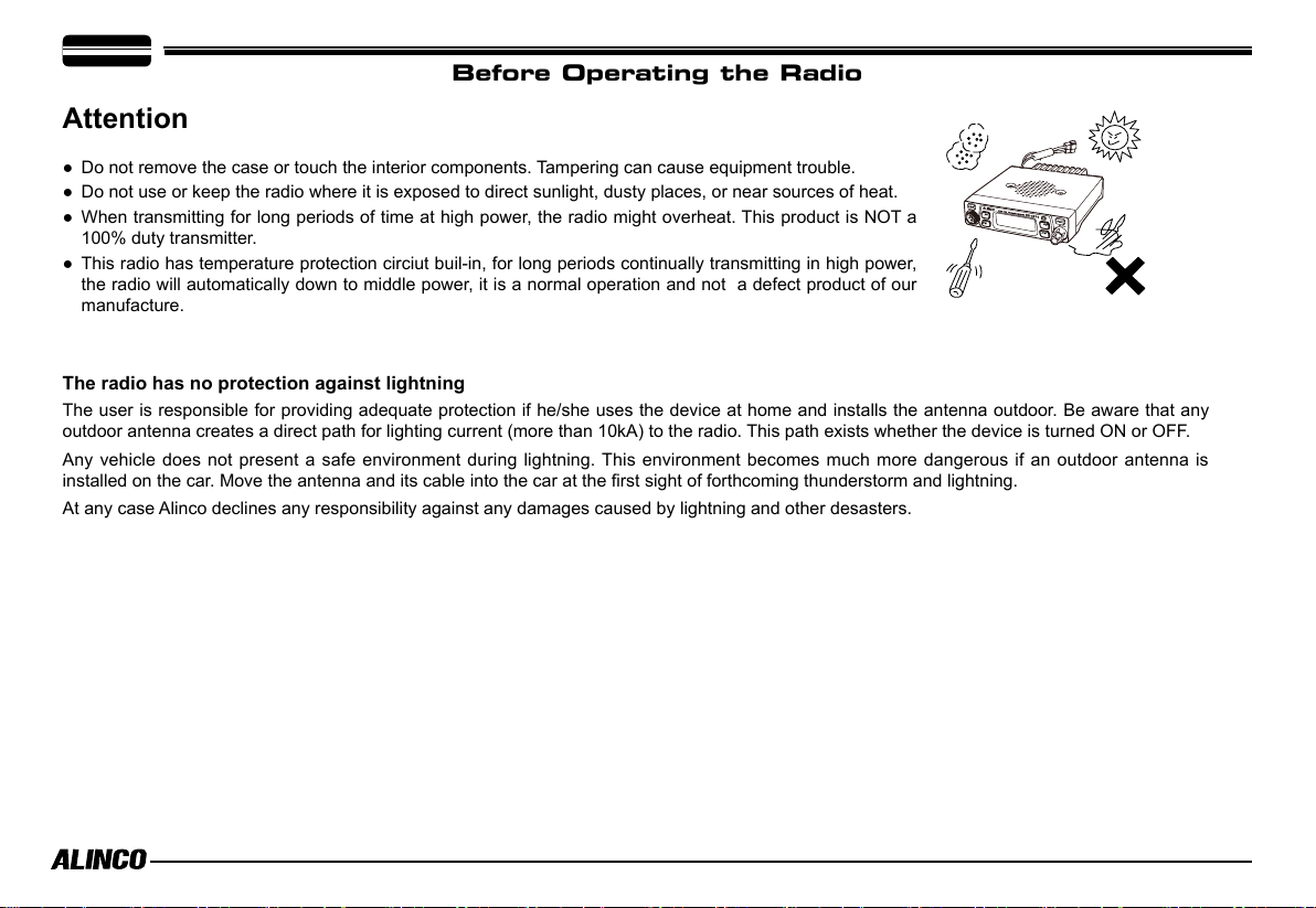
Before Operating the Radio
Attention
● Do not remove the case or touch the interior components. Tampering can cause equipment trouble.
● Do not use or keep the radio where it is exposed to direct sunlight, dusty places, or near sources of heat.
● When transmitting for long periods of time at high power, the radio might overheat. This product is NOT a
100% duty transmitter.
● This radio has temperature protection circiut buil-in, for long periods continually transmitting in high power,
the radio will automatically down to middle power, it is a normal operation and not a defect product of our
manufacture.
The radio has no protection against lightning
The user is responsible for providing adequate protection if he/she uses the device at home and installs the antenna outdoor. Be aware that any
outdoor antenna creates a direct path for lighting current (more than 10kA) to the radio. This path exists whether the device is turned ON or OFF.
Any vehicle does not present a safe environment during lightning. This environment becomes much more dangerous if an outdoor antenna is
installed on the car. Move the antenna and its cable into the car at the first sight of forthcoming thunderstorm and lightning.
At any case Alinco declines any responsibility against any damages caused by lightning and other desasters.
Page 6
CONTENTS
Supplied Accessories/Optional Accessories .....................1
Supplied Accessories ....................................................................... 1
Initial Installation ..................................................................2
Mobile installation ............................................................................2
DC Power Cable Connection ........................................................... 3
Power supply voltage Display .......................................................... 5
Antenna Connection ........................................................................5
Accessories Connections .................................................................5
Getting Acquainted ..............................................................7
Front panel ....................................................................................... 7
Rear panel .......................................................................................8
Display ............................................................................................. 8
Microphone ..................................................................................... 9
Basic Operations ................................................................. 10
Switching the Power On/Off ............................................................10
Adjusting the Volume ......................................................................10
Switch between VFO and Memory mode .......................................10
Adjusting Frequency/Channel Through Selector Knob .................... 10
Adiusting squelch level ....................................................................10
Receiving ......................................................................................... 10
Transmitting .....................................................................................10
Transmitting T
Transmitting Optional Signaling .......................................................11
Memory Channel Programming ....................................................... 11
Memory Channel DeletIng ............................................................... 11
one Burst Tone ..........................................................11
KEY OPERATIONS ................................................................ 12
Squelch Off/Squelch Off Momentarry ..............................................12
Frequency Scan ............................................................................... 12
Memory Scan ................................................................................... 12
CTCSS/DCS Encode and Decode setup ......................................... 12
CTCSS SCAN .................................................................................. 13
DCS SCAN ......................................................................................13
High/Mid/Low Power switch ............................................................. 13
Compander ...................................................................................... 13
Offset Direction and offset frequency setup .....................................13
Keypad Lockout ............................................................................... 14
Auto-Dialer Setup .............................................................................14
Emergency Alarm .............................................................................14
FUNCTION MENU SETUP ....................................................15
Frequency Channel Step Setup ....................................................... 15
DTMF, DTMF ANI, 2Tone or 5Tone Signaling .................................. 15
Sending 2-Tone Call .........................................................................16
Sending 5-Tone Call .........................................................................16
Sending DTMF call ..........................................................................16
Signaling Combination setup ........................................................... 17
High/Mid/Low Power Selection ........................................................ 17
Band-width Selection ....................................................................... 17
T
X OFF Setup .................................................................................. 18
Busy Channel Lockout ..................................................................... 18
Editing Channel NAME ................................................................... 18
Page 7
CONTENTS
Reverse TX/RX ................................................................................18
Talk Around ..................................................................................... 19
Radio's DTMF Self ID Enquiry ......................................................... 19
Radio's 5TONE Self ID Enquiry .......................................................19
Beep Sound ..................................................................................... 19
TOT (Time-out timer) .......................................................................19
APO (Auto power off) .......................................................................20
DTMF Transmitting Time ..................................................................20
Display Iiiumination Color Setting .................................................... 20
Scan Resume Time Setup ...............................................................20
Tone-burst Tones ............................................................................. 21
Display Mode Setup ......................................................................... 21
PIN Setup(
Address list .....................................................................................21
RESET (
Useless if PIN is not assigned
May be blocked for dealer-programmed units
) .................................21
) ......... 22
Microphone Operation .........................................................23
Keypad Lock .................................................................................... 23
Transmitting DTMF By Microphone KeyPAD ................................... 23
Function Setup By Microphone Keypad ...........................................23
Switches between VFO and memory mode ....................................23
Short Calling ...................................................................................23
Frequency Step ...............................................................................23
Optional signaling ...........................................................................23
Scan Skip ........................................................................................ 24
Frequency/Channel scan ................................................................ 24
Busy Channel Lockout ..................................................................... 24
Reverse TX/RX ................................................................................ 24
TOT (Time-out timer) .......................................................................24
CTCSS/DCS Encode and Decode ...................................................24
Talk Around ..................................................................................... 25
Beep Sound ..................................................................................... 25
HIGH/MID/LOW Power Selection .................................................... 25
LCD Backlight ................................................................................ 25
Cable Clone ........................................................................... 26
OPTIONAL ACCESSORIES ..................................................26
Maintenance .......................................................................... 27
Key Function .................................................................................... 27
Trouble Shooting ..............................................................................27
Specications .......................................................................28
Appendix ...............................................................................29
51 groups CTCSS Tone Frequency(Hz). .........................................29
1024 groups DCS Code. .................................................................. 29
Page 8

Supplied Accessories
Supplied Accessories
Carefully unpack to make sure the following items are found in the package in addition to this manual:
1
Transceiver
DR-CS10
Microphone EMS-74
(with DTMF keyboard)
Mobile Mounting
Bracket
DC Power Cable with
Fuse Holder(ADUA38)
Spare Fuses(15A)
The standard accessories may vary slightly depending on the version you have purchased. Please contact
your local authorized Alinco dealer should you have any questions. Alinco and authorized dealers are not
responsible for any typographical errors there may be in this manual. Standard accessories may change
without notice.
Warranty Policy: Please refer to any enclosed warranty information or contact your authorized Alinco dealer /
distributor for the warranty policy before purchase.
■
In order to operate this product, a properly tuned antenna, its feedline with hardwares and
in case of fixed station a 20A-class power supply are necessary.
Please consult with your dealer for details.
Hardware Kit for Bracket
Fixing screws
(
M5x10mm
(2PCS)
Tapping screws
(
M4x12mm
(2PCS)
Pads
)
(2PCS)
S-Washer
)
(2PCS)
1
Page 9
2
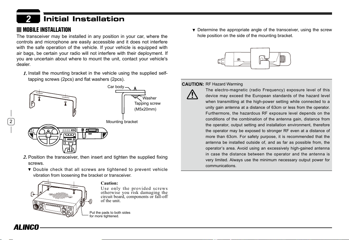
Initial Installation
Mobile installation
The transceiver may be installed in any position in your car, where the
controls and microphone are easily accessible and it does not interfere
with the safe operation of the vehicle. If your vehicle is equipped with
air bags, be certain your radio will not interfere with their deployment. If
you are uncertain about where to mount the unit, contact your vehicle's
dealer.
Install the mounting bracket in the vehicle using the supplied self-
1.
tapping screws (2pcs) and at washers (2pcs).
Car body
Washer
Tapping screw
(M5x20mm)
2
Position the transceiver, then insert and tighten the supplied fixing
2.
screws.
Double check that all screws are tightened to prevent vehicle
vibration from loosening the bracket or transceiver.
Mounting bracket
Caution:
Use only the provided screws
otherwise you risk damaging the
circuit board, components or fall-off
of the unit.
Determine the appropriate angle of the transceiver, using the screw
hole position on the side of the mounting bracket.
CAUTION:
RF Hazard Warming
The electro-magnetic (radio Frequency) exposure level of this
device may exceed the European standards of the hazard level
when transmitting at the high-power setting while connected to a
unity gain antenna at a distance of 63cm or less from the operator.
Furthermore, the hazardous RF exposure level depends on the
conditions of the combination of the antenna gain, distance from
the operator, output setting and installation environment, therefore
the operator may be exposed to stronger RF even at a distance of
more than 63cm. For safety purpose, it is recommended that the
antenna be installed outside of, and as far as possible from, the
operator’s area. Avoid using an excessively high-gained antenna
in case the distance between the operator and the antenna is
very limited. Always use the minimum necessary output power for
communications.
Put the pads to both sides
for more tightened.
Page 10
DC Power Cable Connection
Mobile Operation
The vehicle battery must have a nominal rating of 12V. Never
connect the transceiver to a 24V battery. Be sure to use a 12V
vehicle battery that has sufficient current capacity. If the current
to the transceiver is insufficient, the display may darken during
transmission, or transmitting output power may drop excessively.
Route the DC power cable supplied with the transceiver directly
1.
to the vehicle's battery terminals using the shortest path from the
transceiver.
Never use the cigarette lighter socket as a DC source.
The entire length of the cable must be dressed so it is isolated from
heat, moisture, and the engine secondary(high voltage) ignition
system/cables.
After installing cable, in order to avoid the risk of damp, please
2.
use heat-resistant tap to tie together with fuse box. Don't forget to
reinforce whole cable.
In order to avoid the risk of short circuit, please cut down
3.
connection with negative (-) of battery, then connect with radio.
Confirm the correct polarity of the connections, then attach the
4.
power cable to the battery terminals; red connects to the positive (+)
terminal and black connects to the negative (-) terminal.
Never remove the fuse holders from the cable.
Reconnect any wiring removed from the negative terminal.
5.
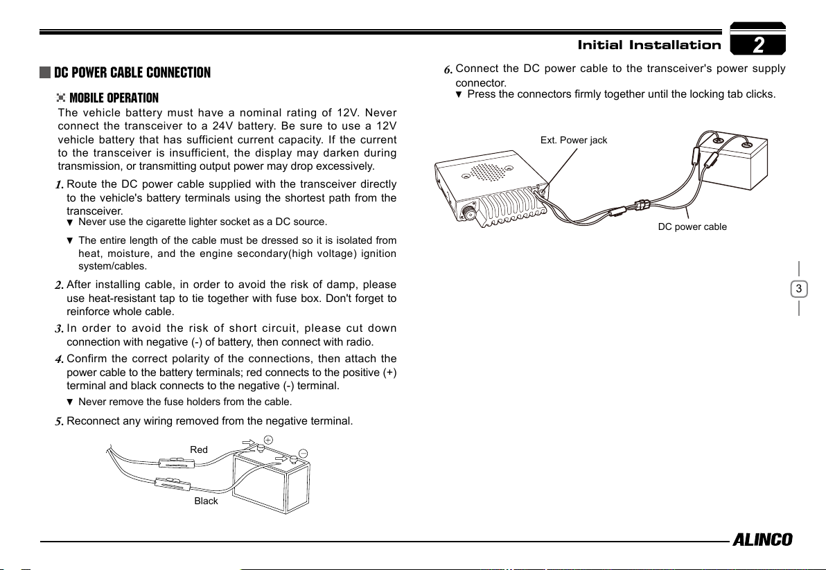
Initial Installation
Connect the DC power cable to the transceiver's power supply
6.
connector.
Press the connectors firmly together until the locking tab clicks.
Ext. Power jack
DC power cable
2
3
Red
Black
Page 11

2
Fixed Station Operation
In order to use this transceiver for fixed station operation, you will need
a separate 13.8V DC power supply (not included) , Please contact local
dealer to require.
The current capacity of your power supply must be 12A or more.
Initial Installation
Connect the DC power cable to the regulated DC power supply
1.
and ensure that the polarities are correct. (Red: positive, Black:
negative).
Never directly connect the transceiver to an AC outlet.
Use the supplied DC power cable to connect the transceiver to a
regulated power supply.
Do not substitute a cable with smaller gauge wires.
Connect the transceiver's DC power connector to the connector on
2.
the DC power cable.
Press the connectors firmly together until the locking tab clicks.
Before connecting the DC power to the transceiver, be sure to
switch the transceiver and the DC power supply OFF.
Do not plug the DC power supply into an AC outlet until you make
all connections.
REPLACING FUSES
If the fuse blows, determine the cause, then correct the problem. After the
problem is resolved, replace the fuse. If newly installed fuses continue to
blow, disconnect the power cable and contact your dealer for assistance
.
4
Black
DC power cable with fuse holder
Regulated
power supply
Red
Fuse Location Fuse Current Rating
Transceiver 15A
Supplied Accessory DC
power cable
Only use fuses of the specified type and rating, otherwise the transceiver
could be damaged.
If you use the transceiver for a long period when the vehicle battery is
not fully charged, or when the engine is OFF, the battery may become
discharged, and will not have sufficient reserves to start the vehicle. Avoid
using the transceiver in these conditions.
15A
Page 12
Power supply voltage Display
After being connected to an appropreate power source, press
to turn on. Press and hold
voltage.
The display immediately changes as the voltage supply changes, It also
displays voltage during transmission.
The transceiver will return to its normal operation when the power is
turned ON/OFF or repeat above operation.
The range of displayed voltage is from 9V to16V DC. Because the
displayed value is estimated, please use a voltmeter when a more
Important
precise reading is desired.
P3
key for 2 seconds to display the supplied
PWR
key
Antenna Connection
Before operating, install an efficient, well-tuned antenna. The success
of your installation will depend on the type of antenna and its correct
installation.
Use a 50Ω impedance antenna and low-loss coaxial feed-line that
has a characteristic impedance of 50Ω, to match the transceiver input
impedance. Coupling the antenna to the transceiver via feed-lines having
an impedance other than 50Ω reduces the efficiency of the antenna
system and can cause interference to nearby televisions, radio receivers
and other electronic equipment.
Transmitting without first connecting an antenna or other matched
load may damage the transceiver. Always connect the antenna to the
transceiver before transmitting.
All fixed stations should be equipped with a lightning arrester to reduce
the risk of fire, electric shock, and transceiver damage.
Initial Installation
2
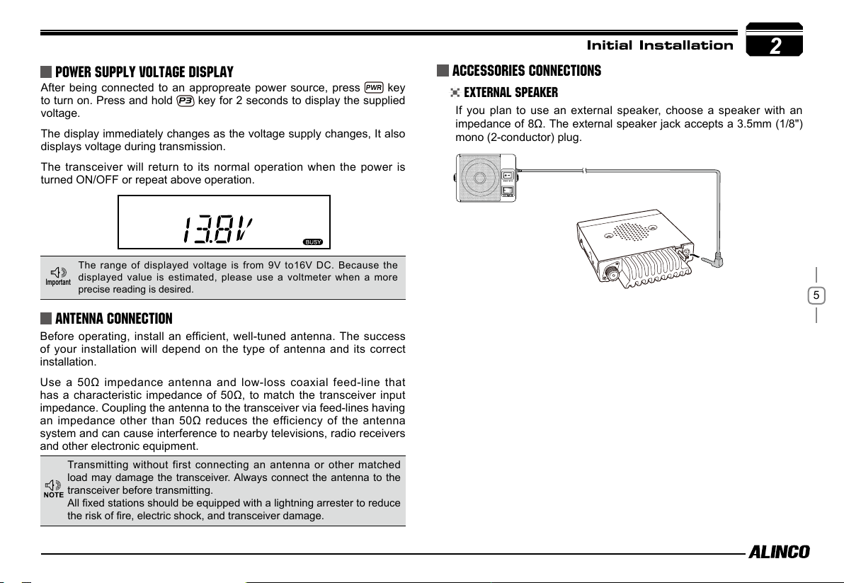
Accessories Connections
External Speaker
If you plan to use an external speaker, choose a speaker with an
impedance of 8Ω. The external speaker jack accepts a 3.5mm (1/8")
mono (2-conductor) plug.
5
Page 13

2
Initial Installation
Microphone
For voice communications, connect a provided microphone into the
socket on the front of the main unit. Turn the ring firmly on the plug
until it locks. Attach the supplied microphone hanger in an appropriate
location using the screws included in the screw set.
Microphone
connector
6
Microphone [EMS-74]
Antenna
External speaker
Page 14

Front panel
P3
P2
Basic Functions
NO. KEY FUNCTION
1 PWR(Power) Power on/Off
2 VOL
3
4 FUNC Various functions
5 P1
6 P2 Changes frequency by 1MHz order
7 P3 Sets CTCSS and DCS values
8 P4
9
Knob
SQL Knob Adjust Squelch level
Data Terminal
/Mic.connector
Adjust audio level
Switches between VFO mode and Memory mode
Call channel
Data reading/writing, cloning and Microphone
connection port
P4
Getting Acquainted
Functions that require pressing
press the following key.
FUNC
key until icon appears then
3
NO. KEY FUNCTION
FUNCPWR
1 P1 MW(Setting memory channel data)
2 P2 Deleting memory channel
3 P3
Keypad lockout
4 P4 High/Middle/Low power
Functions that require holding for over 2 seconds the following key.
NO. KEY FUNCTION
1 FUNC Goes to FUNCTION MENU
2 P1 SCAN
3 P2
4 P3
5 P4 --
Functions that require continuous pressing following key to be
activated.
Frequency Offset
Power voltage monitor
7
NO. KEY FUNCTION
1 FUNC+P4+PWR(ON) Reset to factory default settings
The functions of keys may vary due to dealer programming.
In case the transceiver functions differently or doesn't work, please contact to
the dealer who programmed your transceiver.
Page 15

3
Getting Acquainted
Rear panel
3
NO. Jack Connectors FUNCTION
1 Ext. Sp Terminal for optional external speaker.
Repeater
2
8
Terminal
Antenna
3
Connector
Terminal for repeater connection.
Connection for 50Ω coaxial cable and
antenna.Connector is PL/M.
DISPLAY
14
19
1
2
16
17
18
13
15
12
13
10
11
NO. KEY
1
1 SQL
2 M
3
4
2
5
6
7
8
9
10
11
12
13
14
15
9
16
17
18
8
19
Å
Dot
Decimal point
DCS
_
+
A
Nar
LO
Mi
FUNCTION
(Not in use)
Memory mode.
Indicates the channel number in memory mode.
Channel skip.
Indicates the decimal point of frequency and the
scanning function.
Indicates the frequency or memory name.
Signal is being received or monitoring.
Signal strength of receiving and transmitting.
Strength of receiving or transmitting signals.
(Not in use)
Keypad lock .
Set DCS function.
Set CTCSS function.
Offset frequency direction.
(Not in use)
Auto power off.
Narrow mode.
Low power.
Middle Power.
Function key is activated
3
4
5
6
7
Page 16

microphone
NO. KEY FUNCTION
UP Increase frequency, channel number or setting value.
1
DOWN Decrease frequency, channel number or setting value.
2
PTT Push-To-Talk key to transmit.
3
Numerical Keyd Input VFO frequencies and other various oprations.
4
MIC Connector Diagram(
Getting Acquainted
in the front view of connector)
3
9
DTMF ON/OFF
5
LOCK Switch Locks all keys excep PTT.
6
MIC Microphone element is located.
7
Switches between DTMF and function operations.
Page 17

Basic
4
Switching The Power On/Off
Press the
PWR
PWR
key for 1 second to turn off.
switch to power on. Press the
Adjusting The Volume
Turn the VOL knob clockwise to increase the
audio level, counterclockwise to decrease.
Operations
PWR KEY
PWR
P2
P3
P4
ADJUSTING SQUELCH LEVEL
A squelch eliminates white-noise (the background noise when a signal is
not received). Higher level settings will keep the squelch "closed" more
10
tightly for quieter monitoring, but weak signals will not be heard. Lower
settings allow weaker signals to "open" the squelch but noise may also
cause it to open. By rotating the SQL knob, adjust the squelch level to
the desired level.
Switch between VFO and MEMORY mode
In standby, press key or Microphone's
key until appear , this indicates current
frequency in Memory mode. Repeat above
operation to switch between Frequency mode
(VFO) and
Memory mode.
FUNC
Adjusting Frequency/Channel
In frequency (VFO) mode, you can change the current frequency to
1.
the desired one through microphone [
key to increase frequency and press key to decrease
frequency. In another way you also can directly input the desired
frequency by MIC's numeric keys. Press
digits will be masked. In this status, Microphone [
] key will increase or decrease frequency quickly by 1MHz
step.
In memory mode, you can change the current channel to the
2.
desired one through microphone [
key to the forward channel and press key to the
backward channel. In another way you also can directly input the
desired channel by MIC`s numeric keys. For example, choosing
CH1, press [0] [0] [1] .
Available steps are 2.5K, 5K, 6.25k, 8.33K,10K, 12.5K, 20K, 25K and 30K.
/ ] key. Press
P2
key, the KHz order
/ ] key. Press
/
Receiving
Select the desired receiving frequency or browse channels to listen to
ongoing communications. The S-meter shows
relative signal strength between BUSY and
5th segment when the transceiver detects an
incoming signal.
Transmitting
Press MIC's key to monitor for a while to confirm the channel
desired is not busy. Press Mic's
press and hold [PTT] key to speak into microphone.
key to return standby status,Then
Page 18

Speaking too loud distorts, too undertone won't modulate enough your
voice.
While transmitting, LED lights RED and TX-meter shows relative power level.
Release PTT to receive.
Transmitting Tone BURST TONE
Press and hold [PTT] key, then press Microphone key to transmit
selected tone-burst tone. Pre-programming is necessary.
Transmitting OPTIONAL SIGNALING
Press and hold [PTT] key, then press Microphone
transmit pre-stored and selected DTMF/2Tone/5Tone optional signaling.
Preprogramming is necessary.
key to
Basic Operations
MEMORY CHANNEL DELETING
Under Memory mode, input by MIC's numeric keys to select
1.
channel to be deleted. For example, choosing CH1, press [0] [0] [1].
FUNC
Press
2.
memory will be deleted and a beep sounds twice.
means current memory channel is deleted. Can not delete all
memory channels, at least one channel will be saved.
key, LCD appears icon, then press P2 key, current
icon ashing
4
MEMORY CHANNEL PROGRAMMING
In frequency mode (VFO), select the desired frequency.
1.
P3
Press
2.
See next page for more details.
Press
3.
current channel appear on LCD. Flashing
Press or Key to select the
4.
desired channel number to store.
Press key, , icon and channel
5.
number disappears and beep sounds twice.
Press key again to confirm that the memory channel is properly
6.
stored.
key to enter CTCSS/DCS signaling setup, press microphone
or key to select the desired signaling in case you need.
FUNC
key, LCD appears , and
means the current channel is empty.
11
Page 19

KEY OPERATIONS
5
squelch off(Monitor function:)
Squelch Off: Press key to disable squelch, press key again
to resume squelch. While monitoring, all signaling features are
temporary released.
Frequency Scan
Scans all VFO frequencies in regard to the preset tuning step.
In VFO mode, press until starts
1.
scanning.
Press Microphone [ / ] key to change scan direction.
2.
12
Press any key except
3.
PWR
and
FUNC
key to stop.
MEMORY Scan(channel scan)
Scans all memory channels unless Memory skip feature is selected for a
given memory.
In memory mode, press and hold key for over 2 seconds to
1.
enter into channel scan.
Press Microphone [ / ] key
2.
to change scan direction.
Press any key except
3.
exit.
PWR
and
FUNC
key to
CTCSS/DCS Encode and Decode setup
Many repeaters require CTCSS or DCS
tone encoding to access the system. Tone
decoding features are often used to filter
unwanted signals. In this mode, regardless
of the main squelch status, the audio can
be heard ONLY when the matching tone/
code signal is received. The combination
of CTCSS squelch and DCS function is not
available; only one or the other may be used
for a given channel. Tone settings can be
programmed in memory channels. In memory mode, the setting may
be changed temporary but changing a channel or turning off the radio
will cancel the operation and returns to programmed setting.
Press P3 key. The current setting will be displayed with T/SQ/DCS
1.
icons and relative frequency/code.
Select icon to set the encoding tone.The number below
2.
represents the tone frequency in Hz. Use [
to select the desired encoding tone.If the repeater requires only
encoding tone, press [PTT] to set and operate.
To set tone squelch, Press P3 key again to display icon.
3.
Select decoding tone frequency that can be set different from
encoding tone. Press [PTT] to set and operate tone-squelch.
Press it again so that the 3-digit number and icon is displayed.
4.
This is the DCS code, and it enables DCS encoding and decoding.
Press [
FUNC / PWR / TS / DCS, UP / DOWN keys) to enter the setting and
return to original status. The T/SQ/DCS icon will remain on the display to
show the current selective-calling status. To exit, simply use the
and press it until the relative status icon T/TQ/DCS disappears.
/ ] keys to change codes. Press any key ( Except
/ ] keys
P3
key
Page 20

The standard set of 50 different CTCSS tones are available. DCS
encode/decode cannot be separated. The list of selectable tones and
codes is shown on Appendix at the end of this manual.
CTCSS SCAN
While receiving CTCSS signal, press P3 key
to select
starts scanning. Once finding a matching
CTCSS tone, a voice will be heard and
resumes scanning after 15 seconds.
or TSQ then hold P3 key until
KEY OPERATIONS
5
Offset Direction and offset frequency setup
Repeater receives a signal(UP-LINK) on one frequency and re-transmits
on another frequency(DOWN-LINK). The difference between these two
frequencies is called the offset frequency. If the UP-LINK frequency is
higher than DOWN-LINK frequency, the direction is positive, If it is lower,
the shift direction is negative.
Once the radio is turned off or switched to another channel, the
temporary setting will be erased.
DCS SCAN
While receiving DCS signal, press
P3
key until starts scanning. Once finding a
matching DCS code, a voice will be heard and
resumes scanning after 15
seconds.
P3
key to select DCS then hold
HIGH/MID/LOW Power SETTING
FUNC
Press
P4
power.
None: T
key to display icon, then press
key to switch between high/Mid/low
ransmits in high power
: Transmits in middle power
: Transmits in low power
Press and hold P2 key for over 2
1.
seconds, LCD displays offset direction
and offset frequency.
Repeatedly press P2 key to select
2.
positive offset or negative offset.
When LCD displays " " icon, it indicates positive offset, which
3.
means transmitting frequency higher than receiving frequency.
When LCD displays " " icon, it indicates negative offset, which
4.
means transmitting frequency lower than receiving frequency.
Mic's [ / ] key to change offset frequency in
5.
accordance with the step setting.
Press any key except
6.
In memory mode, this operation can be temporarily available.
FUNC
and P2 key to set and finish setting.
13
Page 21

5
KEY OPERATIONS
KEYPAD LOCKOUT
Avoiding unintentional operation, this function will lock all keys except
FUNC
PWR
and
1.
2.
.
FUNC
Press
icon, then press
displays icon.
Repeat above operation, icon disappears, indicating keypad
lockout function is invalid.
key until LCD displays
P3
key until LCD
Auto-Dialer Setup
This will automatically transmit pre-programmed and stored DTMF tones.
To operate this function on the radio keys, it is necessary to be
programmed by PC software, by the "DTMF set" function. Please ask to
14
the dealer. Or you can directly press Mic's
you wish to transmit automatically.
While pressing programmed DTMF Set key to enter the auto-dialer
enquiry mode, LCD displays current default data and current group
displayed on left. If no data in current group, it shows "EMPTY".
Press / to choose group you wish to edit. Up to 16
1.
Auto-dialer memories are available. The display scrolls when the
7th digit is entered. The numbers 0-9, --,
A-D, * and # can be stored up to a total
of 24 digits.
Press key to program the DTMF you
2.
wish to transmit automatically.
After editing, press [PTT] key to send
3.
current auto-dialer tones. Press
exit and store.
key to program the DTMF
P4
to
Emergency Alarm
This transceiver has 4 optional Alarm modes that can only be set using
programming software. Press pre-programmed key to display "ALARM"
to operate. Repeat above operation or turn off the transceiver to cancel
the alarm.
Page 22

FUNCTION MENU SETUP
7
IMPORTANT: All or a part of operation in this chapter may not be
available to dealer-programmed units.
Press and hold
1.
FUNC
key for over 2 seconds to enter the FUNCTION
MENU SETUP.
Press P3 or P4 to select the desired menu. P3 key to forward
2.
P3
and
key to backward menus.
Press / to select the desired parameter.
3.
P2
Press
4.
Menu No. LCD Display
to confirm and exit.
01 STP (Channel Step) 12.5K
Å
02 T (DTMF,2 TONE, 5 TONE Of RX) OFF
03 2TONE (TX) 00
04 5TONE (TX)
05 DTMF (TX)
06 SPK (Signal Combination) SQ
07 POWER HIGH
08 BAND 25K
09 TX ON
10 LOCK(Busy Channel Lock Out) OFF
11 Editting Channel Name -
12 REV (Reverse TX/RX) OFF
13 TALK (Talk Around) OFF
14 D (DTMF Self ID Enquiry) 001
15 F (5 TONE Self ID Enquiry) 12345
16 BEEP (Beep Sound) ON
17 TOT (Time Out Timer) 3 Minutes
18 APO (Auto Power Off) OFF
19 SPD (DTMF Transmitting Time) 50
20 COL (Display Color) ORG
21 SCAN T0
22 TB (Tone-Bust Tones) 1750
23 DSP (Display Mode Setup) FR
24 CODE OFF
25 BOOK (Address List) -
26 RESTORE -
Default
00
01
Frequency Step Setup
Only in VFO mode, this function is valid.
Press and hold
1.
FUNC
key for over 2
seconds to enter setting menu.
2.
Press
key to choose No.01 menu, LCD displays "STP--
/
P4
P3
125".
Press / to select the desired frequency channel step.
3.
Available steps in KHz are: 2.5(shown as 2K5), 5, 6.25(62), 8.33(83),
10, 12.5(125), 20, 25, 30 and 50.
Press P2 key to confirm and exit.
4.
This function is not available in memory-mode.
RECEIVING DTMF, DTMF ANI, 2TONE OR 5TONE SIGNALING
DTMF/5Tone/2Tone signalling are used for selective-calling. DTMF
and 5Tone signalling can be applied for other advanced features such
as ANI, PTT ID, group call,
The signalling edition must be done in advance to operates through
programming software.
Press and hold
1.
menu.
Press
2.
Press / to select the desired setup.
3.
"DTMF”: The channel will be mute by a DTMF signal. The
to choose No. 2 menu, LCD displays "T-OFF" .
/ P4
P3
speaker won’t sound until receiving
a correspondent DTMF signal. Hold
[PTT] then press [UP] directly to
transmit the pre-stored DTMF tones.
remotely stun, remotely kill, revive,...etc.
FUNC
key for over 2 seconds to enter into setting
15
Page 23

7
"2TONE": The channel will be mute
by a 2-Tone signal. The speaker won’t
sound until receiving a correspondent
2-Tone signal. Hold [PTT] then press
[UP] to transmit the pre-stored 2-Tone
signal.
"5Tone": The channel will be mute by
a 5-Tone signal. The Speaker won’t
sound until receiving a correspondent 5-Tone signal. Hold [PTT]
then press [UP]
Press P2 key to confirm and exit.
4.
Sending 2-Tone Call
Press and hold
1.
16
Press P3 /
2.
XX", "XX" indicates the preprogrammed
groups.
Press / to select the
3.
desired 2-TONE group, Press PTT to
transmit selected group.
Total:32groups, 00-31, Default: 00.
4.
Press
5.
2-TONE will be operation parameters must be edited by
programming software prior to the practical operation.
This function is to only query edited group or name.
FUNCTION MENU SETUP
directly to transmit the pre-stored 5-Tone signal.
FUNC
key for over 2 seconds to enter setting menu.
P4
key to choose No.03 menu, LCD displays "2TON
P2
key to confirm and exit.
Sending 5-Tone Call
Press and hold
1.
Press P3 /
2.
LCD displays "5TON XX", "XX" indicates
the preprogrammed groups.
Press / to select the desired 5-TONE group, Press
3.
[PTT] to transmit selected group.
Total:100groups, 00-99, Default:00.
4.
Press P2 key to confirm and exit.
5.
5-TONE operation parameters must be edited by programming
software prior to the practical operation.
FUNC
key for over 2 seconds to enter setting menu.
P4
key to choose No.04 menu,
Sending DTMF call
Press and hold
1.
P3
Press
2.
XX", "XX" indicates the operation parameters must be.
Press / to select the desired
3.
DTMF group.
Total:16groups, 01-16, Default:01.
4.
Press P2 key to confirm and exit.
5.
FUNC
key for over 2 seconds to enter setting menu.
/ P4 key to choose No.05 menu, LCD displays "DTMF
Page 24

Signaling Combination setup
This function is to improve the level of protecting the radio against
receiving irrelative signal.
Press and hold
1.
P3
Press
2.
SQ".
Press / to select the desired combination.
3.
If select "SQ", it indicates you can hear
the calling from caller when receive a
matching carrier.
If LCD displays "CTC", it indicates
you can hear the calling from caller
when receive a matching carrier and
CTCSS/DCS signaling .
If LCD displays "TON", it indicates
you can hear the calling from caller
when receive a matching carrier and
DTMF/2TONE/5TONE signaling .
If LCD displays "C/T", it indicates
you can hear the calling from caller
when receive a matching carrier and
CTCSS/DCS and DTMF/2TONE/5TONE signaling.
If LCD displays "C/T", it indicates you
can hear the calling from caller when
receive a matching carrier and
CTCSS/DCS DTMF/2TONE/5TONE signaling.
Press P2 key to confirm and exit.
4.
This function is available only for pre-programmed units with
Tone-signals and CTCSS/DCS selective calling.
FUNC
key for over 2 seconds to enter setting menu.
/ P4 key to choose No.06 menu, LCD displays "SPK--
either
FUNCTION MENU SETUP
HIGH/MID/LOW Power Selection
Press and hold
1.
seconds to enter setting menu.
P3
Press
2.
menu, LCD displays "POW--HI".
Press / to select the desired setting.
3.
HI: High TX Power (60W)
MI: Middle TX Power (25W)
LOW: Low TX Power (10W)
Press P2 key to confirm and exit.
4.
FUNC
key for over 2
P4
/
key to choose No.07
Band-width Selection
Select suitable bandwidth in accordance with your local band-plans.
Press and hold
1.
P3
Press
2.
menu, LCD displays "BAND--25".
Press / to select the
3.
desired setting.
25:Band width is 25KHz(Wide band)
20:Band width is 20KHz(Middle band)
12:Band width is 12.5KHz(Narrow band)
Press P2 key to confirm and exit.
4.
FUNC
key for over 2 seconds to enter setting menu.
P4
/
key to choose No.08
7
17
Page 25

7
FUNCTION MENU SETUP
TX OFF SETUP
This function is to prohibit the transmission and to use the radio as a
receiver.
Press and hold
1.
P3
Press
2.
Press / to select the
3.
desired setting.
On:In current channel, press PTT to
transmit
OFF:In current channel, PTT is invalid.
4. Press
18
BCLO is to disable transmitting while RX signal is received. Once the
channel is busy and you press PTT, the radio will beep as warning and
get back to receiving.
P2
Busy Channel Lockout
Press and hold
1.
seconds to enter setting menu.
Press P3 /
2.
menu, LCD displays "LOCK--OFF".
Press / to select the
3.
desired setting.
BU: Enable BCLO, Carrier lockout, transmitting is inhibited when
current channel receives a carrier.
RL: Enable BTLO, transmitting is inhibited when current channel
receives a carrier but dis-matching CTCSS/DCS.
FUNC
key for over 2 seconds to enter setting menu.
P4
/
key to choose No.09 menu, LCD displays "TX-ON".
key to confirm and exit.
FUNC
key for over 2
P4
key to choose No.10
OFF: Busy channel lockout is disabled. It can transmit in any
receiving status.
Press P2 key to confirm and exit.
4.
Editing Channel NAME
In memory-mode, press and hold
1.
for over 2 seconds to enter setting menu.
Press P3 /
2.
menu, LCD displays cursor and ashing.
Press / to select the desired letter, press P2 key
3.
to confirm selected letter and enter into next edition, press
return forward edition.
After edition, press
4.
In Frequnecy display (VFO)mode, this menu is not available.
P4
(Available only in Memory mode)
FUNC
key
key to choose No.11
FUNC
key to exit.
P1
to
Reverse TX/RX
TX frequency turns to RX frequency & RX frequency changes to TX
frequency. CTCSS/DCS setting is respected also.
Press and hold
1.
Press P3 /
2.
menu, LCD displays "REV—OF".
Press / to select the
3.
desired setting.
ON:Enable Frequency Reverse
OFF:Disable Frequency Reverse.
Press P2 key to set and exit.
4.
FUNC
key for over 2 seconds to enter setting menu.
P4
key to choose No.12
Page 26

Talk Around
By Talk Around function, you can directly communicate with other radios
in your group in case the repeater is not activated or when you are out of
the repeater range. The transceiver will transmit by RX frequency with its
CTCSS/DCS signaling.
Press and hold
1.
seconds to enter setting menu.
Press P3 /
2.
menu, LCD displays "TALK—OF".
Press / to select the desired
3.
setting.
ON:Enable Talk Around
OFF:Disable Talk Around
After edition, press P2 key to exit.
4.
FUNC
key for over 2
P4
key to choose No.13
Radio's DTMF SELF ID ENQUIRY
Press and hold
1.
menu.
Press P3 /
2.
menu, LCD displays "D--XXX". XXX is
radio's DTMF
Press P2 key to confirm and exit.
3.
FUNC
key for over 2 seconds to enter general setting
P4
key to choose No.14
SELF ID.
Radio's 5TONE SELF ID ENQUIRY
Press and hold
1.
Press P3 /
2.
XXXXX", "XXXXX" is radio's 5TONE
SELF ID.
Press P2 key to confirm and exit.
3.
FUNC
key for over 2s to enter general setting menu.
P4
key to choose No.15 menu, LCD displays"F--
FUNCTION MENU SETUP
7
beep sound
The beep provides confirmation of entry, error status or malfunctions of
the radio. You can enable or disable beep sounds.
Press and hold
1.
seconds to enter setting menu.
Press P3 /
2.
menu, LCD displays "BEEP--ON".
Press / to select the
3.
desired setting.
ON:Enable beep sounds.
OFF:Disable beep sounds.
Press P2 key to confirm and exit.
4.
FUNC
key for over 2
P4
key to choose No.16
TOT (Time-out timer)
TOT prohibits the users from transmitting after a certain period of time
has elapsed. When the time is over, transmitting stops and automatically
returns to receiving. Until the PTT is released once and pressed again,
the radio will not transmit.
Press and hold
1.
Press P3 /
2.
Press / to select the
3.
desired timer setting.
Timer:1-30min,each level 1min
OFF: Disable TOT
Press P2 key to confirm and exit.
4.
FUNC
key for over 2 seconds to enter setting menu.
P4
key to choose No.17 menu, LCD displays "TOT--3".
19
Page 27

7
FUNCTION MENU SETUP
APO (Auto power off)
Once APO is activated, the radio will be automatically switched off when
the pre-set time is elapsed.
Press and hold key for over 2
1.
seconds to enter setting menu.
Press P3/
2.
menu, LCD displays "APO--OFF".
Press / to select the
3.
desired setting.
30MIN:Auto power off after 30m
1HOUR:Auto power off after 1h
2HOUR:Auto power off after 2h
OFF:Disable Auto power off
20
Press P2 key to confirm and exit.
4.
P4
key to choose No.18
DTMF Transmitting Time
Press and hold
1.
seconds to enter setting menu.
Press P3/
2.
menu, LCD displays "SPD--50".
Press / to select the desired setting, in miliseconds.
3.
30/50/100/200/300/500, which indicates the time for sending each
DTMF signal & the interval between each DTMF being sent.
Press P2 key to confirm and exit.
4.
FUNC
key for over 2
P4
key to choose No.19
Display iiiumination color setting
This is to select the display illumination color.
Press and hold
1.
Press P3/P4 key to choose No.20 menu, LCD displays "COL--
2.
ORG".
Press / to select the desired color.
3.
ORG: Orange backlight
SAK: (Sakura) light pink backlight
WHI: White backlight
OFF: NO backlight
Press P2 key to confirm and exit.
4.
FUNC
key for over 2 seconds to enter setting menu.
Scan resume Time Setup
There are 3 kinds of scan resume conditions.
Press and hold
1.
seconds to enter setting menu.
Press P3/P4 key to choose No.21
2.
menu, LCD displays "SCAN--TO".
Press / to select the
3.
desired Scan Resume Time.
TO: Timed Scan, it resumes scanning
after receiving 5 seconds or when the
signal is gone, which ever faster.
CO: Busy Scan, it resumes scanning when the receiving signal is
gone.
SE: Stops scanning when a signal is received.
FUNC
key for over 2
Page 28

8
Press P2 key to confirm the selection and exit.
4.
tone-burst tones
Press and hold
1.
Press P3/P4 key to choose No.22
2.
menu, LCD displays "TB--1750".
Press / to select the
3.
desired tone frequency. Available tones
are 1000,1450,1750 and 2100Hz.
Press P2 key to confirm the selection and exit.
4.
Display Mode Setup
There are 3 different display modes: Frequency+Memory mode, Memory
mode & Frequency mode + Memory mode.
Press and hold
1.
Press P3/P4 key to choose No.23 menu, LCD displays "DSP—
2.
FR".
Press / to select the desired mode.
3.
FR: Frequency mode+Memory mode.
CH: Memory mode.
NM: Frequency mode + Memory mode (if
it is named a name tag, name tag will be
shown).
Press P2 key to confirm and exit.
4.
This function may not be available in dealer-programmed units.
FUNC
key for over 2 seconds to enter setting menu.
FUNC
key for over 2 seconds to enter setting menu.
FUNCTION MENU SETUP
PIN Setup(
Enable this function, you have to insert a matching PIN to enter into
normal status when radio is turned on.(The PIN can be assigend by
programming software only.)
Press and hold
1.
seconds to enter setting menu.
Press P3/P4 key to choose No.24
2.
menu, LCD displays "CODE-OF".
Press / to enable/disable
3.
Pin setup.
ON: Turn on Pin setup
OFF:Turn off Pin setup
Press P2 key to confirm and exit.
4.
Useless if PIN is not assigned
FUNC
key for over 2
)
7
Address list
You store desired ID and corresponding ID name in address list. The
LCD displays ID corresponding name if radio received ANI calling and
find matching ID in address list.
Press and hold
1.
setting menu.
Press P3/P4 key to choose No.25
2.
menu, LCD displays "BOOK".
Press P2 to enter into ID setting, press
3.
P3/P4
to select the desired group
(
00-127, total is 128 group ID). Press
/ to select desired number,
P3
press
next edition, press P4 return to forward
edition, press to clear out all digits.
confirm and move cursor to
FUNC
key for over 2 seconds to enter general
21
Page 29

7
4.
5.
6.
FUNCTION MENU SETUP
After finishing edition, press to confirm and enter into edition of
current group's ID corresponding name.Press
select desired letter, press
press
corresponding ID name.
Press P2 to confirm and return into main menu. Repeat above
Step 3 and Step 4 operations to edit multi-ID and corresponding ID
name.
Press
to clear out all letters. 00-127, total 128 group ID and
FUNC
key to return to standby status.
P3
to move cursor to next edition,
/ to
RESET
If your radio seems to be malfunctioning, resetting the microprocessor
may solve the problem. When performing the reset, you may lose
memory data and stored information. Back up or write down important
data before performing the reset.
22
Press and hold
1.
seconds to enter general setting menu.
Press P3/P4 key to choose No.26
2.
menu, LCD displays "RESTORE".
Press / to select the
3.
desired operation.
FACT:Resume factory default for
channel, signaling and general setting.
SETUP:Return initial setup for No.16-No.24 general setting menu.
Press P2 key to perform the reset.
4.
FUNC
key for over 2
Page 30

DOWN
PTT
Lock Switch
You can operate the transceiver by keypad or input desired frequency
or channel through the EMS-74 microphone. Keypad operations may be
blocked for dealer-programmed units.
Keypad Lock
SLIDE the switch to lock position, The lamp is turned off and all keys
are locked except PTT.
Transmitting DTMF By Microphone KeyPAD
Slide DTMF key to DTMF position, press and hold the [PTT] key,
transmitting the desired DTMF signaling by the numeric key directly.
The keypad operation is suspended in DTMF position.
The transmitting tone can't be monitored.
UP
MIC
Numeric Keys
DTMF ON/OFF
Function Setup By Microphone Keypad
Squelch off:In standby, press key, the
squelch is disabled when
in LCD, Press
and the
again to enable squelch
icon disappears.
icon ashed
Microphone Operation
Switches between VFO and MEMORY mode
In standby, press key to switch between memory mode and
Frequency mode (VFO).
Short Calling
Press PTT switch and
DTMF/2TONE /5TONE in current channel.
Transmitting DTMF Code:In standby, press
DTMF data and group. Press [
desired transmitting DTMF group, then Press PTT to transmit.
If no DTMF data in current group, LCD displays "EMPTY", press
key again and input desired DTMF code by keypad, press PTT to
transmit and store DTMF data.
FREQUENCY STEP
Only in VFO mode, this function is valid.
1. Press
2. Press
3. Press any numeric keys to save and exit.
Optional signaling
In standby, press , then press to add
optional signaling, repeat above operation to
set DTMF, 2TONE or 5TONE signaling.
D: DTMF
T: 2-tone
F: 5-tone
, then press , LCD displays "STP--125".
/ to select the desired frequency channel step.
key to transmit the selected
, LCD displays
/ ] key to select the
8
23
Page 31

8
Scan Skip
In memory mode, press
It means current channel is scan skip. Repeat above operation to set
scan or scan skip in current channel. Decimal point dissapears when the
channel is available for scanning.
Microphone Operation
This function can be temporarily used in memory mode. Once the
radio is turned off or switched to another channel, the temporary
setting will be erased and back to initial settings.
To exclude selected channels from memory scanning
(
then press , decimal point appears.
Frequency/Channel scan
In corresponding mode, press then press key to start scanning.
In scanning mode, press
Press [PTT] to stop scanning.
24
/ to change scan direction.
Busy Channel Lockout
BCLO is to disable transmitting while RX signal is received. Once the
channel is busy and you press PTT, the radio will beep as warning and
get back to receiving.
In standby, press , then press to enter into Busy Channel
1.
Lockout.
Press [ / ] to select the desired value.
2.
BU: Enable
current channel receives a matching carrier; press [PTT] to emit
error voice prompt.
RL: Enable BTLO, transmitting is inhibited when current channel
receives a matching carrier but dis-matching CTCSS/DCS. Press
[PTT] to emit error voice prompt It can transmit in any receiving
status.
BCLO, Carrier lockout, transmitting is inhibited when
OFF: Busy channel lockout is disabled.
Press number keys to confirm and exit.
3.
Reverse TX/RX
)
TX frequency turns to RX frequency & RX frequency changes to TX
frequency. The signaling will also be reversed if CTCSS/DCS signaling
exited in this channel.
In standby, press , then press , LCD displays “REV—OF”.
1.
Press [ / ] to select the desired value.
2.
ON:Enable Frequency Reverse
OFF:Disable Frequency Reverse
Press number keys to confirm and exit.
3.
TOT (Time-out timer)
The time-out timer limits the amount of transmitting time. When you
reach the time limit which has been programmed by your dealer, your
transmission will be cut off. In order to transmit again, you must release
PTT button to reset the timer.
In standby, press , then press LCD displays "TOT-X".
1.
Press [ / ] to select the desired value.
2.
Press number key to confirm and exit.
3.
CTCSS/DCS Encode and Decode
In standby, press , then press to enter into CTCSS/DCS
1.
Encode and Decode.
Repeat above operation to set as below:
2.
Page 32

LCD displays icon, it indicates CTCSS encode set in current
channel.
LCD displays and icon, it indicates CTCSS encode and
decode set in current channel.
LCD displays DCS icon, it indicates DCS encode and decode set
in current channel.
In corresponding icon, press [ / ] to select the desired
3.
CTCSS/DCS encode and decode.
Press , , or to confirm and exit.
4.
Talk Around
By Talk Around function, you can directly communicate with other radios
in your group in case the repeater is not activated or when you are out of
the repeater range. The transceiver will transmit by RX frequency with its
CTCSS/DCS signaling.
In standby, press , then press key, LCD displays "TALK--
1.
OF".
Press [ / ] to select the desired setting .
2.
ON:Enable Talk Around
OFF:Disable Talk Around
Press number key to confirm and exit.
3.
BEEP sound
The prompting tone provides confirmation of entry, error status or
malfunctions of the transceiver. You can enable or disable this function.
In standby, press , then press , LCD displays "BEEP--XX”.
1.
Press [ / ] to turn on/off BEEP prompt.
2.
BEEP—OF: turn off the beep;
BEEP—ON: turn on the beep.
Microphone Operation
Press number key to confirm and exit.
3.
HIGH/MID/LOW Power Selection
In standby, press , then press , LCD displays "POW-XX".
1.
Press [ / ] to select the desired power.
2.
HI:High Power
MI:Middle Power
LOW:Low Power
Press number key to confirm and exit.
3.
LCD Backlight
In standby status, press , then press LCD displays "COL-
1.
XX" .
Press [ / ] to select desired backlight.
2.
ORG:Orange backlight
SAK: Sakura backlight (bright pink)
WHI:Whilt backlight
OFF:No backlight
Press number key to confirm and exit.
3.
8
25
Page 33

9
This feature clones the programmed data and parameters in the master unit to slave units.
Pre-programming is required using a dealerware.
1.
2.
Cable Clone
Use optional EDS-29 cloning cable as shown below. Make a master unit by setting and programming it as desired. Turn off both units. Connect the
cable between the DATA jacks on both units.
Master unit: Press programmed CLONE function key (Program the Key by PC) or other way that press and hold Power(On)+ FUNC+ P2 key at the
same time to enter into cloning mode. LCD displays "CLONE".
26
Press master unit's [FUNC] key, LCD displays "CLONEXX". Slave unit displays "CLONEXXX". When the cloning is successfully finished, the slave
3.
unit will restart. Turn off the power, disconnect the cable and repeat step 3 operations to clone the next slave unit.
If the data is not successfully transmitted, turn off both units, make sure the cable connection is correct and repeat the entire operation from the beginning.
10
OPTIONAL ACCESSORIES
- EDS-29 Clone cable
- ERW-12 PC cable
- EMS-74 Microphone
Page 34

Key Function
The function of key combinations can be changed by PC software.
Below is the default setting.
Key
Combination
FUNC "F" is indicated.
P1 V/M SCAN
P2 MHz Frequency Offset
P3 TS/DCS
P4 CALL -- High/Middle/Low power
Short press
Hold for over 2
seconds
Goes to setting menu --
Power voltage
monitor
FUNC+
MW(Setting memory
channel data)
Deleting memory
channel
Keypad lockout
Maintenance
11
Trouble Shooting
Problem Possible Causes and Potential Solutions
+ and - polarities of power connection are
(a) Power is on, nothing
appears on Display.
(b) Fuse is blown.
(c) Display is too dim. Set the LCD backlight parameter properly.
(d) No sound comes from
speaker.
(e) Key and Dial do not
function.
(i) Rotating Dial will not
change memory channel.
(g) PTT key is pressed but
doesn't transmit.
Please contact your dealer when a technical assistance may be
necessary.
reversed. Connect red lead to plus
terminal and black lead to minus terminal of
DC power supply.
Check and solve problem resulting in blown
fuse and replace fuse with a new one.
• Squelch level too hight. Decrease squelch level.
• Selective-calling like TSQ activated. Press
Micro's
Key-lock function is activated. Cancel Key-lock
function.
Transceiver is in CALL mode. Press
• Microphone connection is poor. Connect
microphone properly.
• Antenna connection is poor. Connect antenna
properly.
key to monitor.
.
27
Page 35

12
Specifications
General
Frequency Range VHF: 136-174MHz
Number of Channels
Channel Spacing
Channel step
Operating Voltage 13.8V DC ±15%
Squelch
Frequency Stability ±2.5ppm
Operating Temperature
Dimensions(WxHxD)
28
Weight about 0.910Kg
Specifications are subject to change without notice due to advancements in
technology.
200 channels
25KHz (Wide Band)
20KHz (Middle Band)
12.5KHz (Narrow band)
2.5KHz,5KHz, 6.25KHz, 8.33KHz, 10KHz,
12.5KHz, 15KHz, 20KHz, 25KHz, 30KHz, 50KHz
Carrier/CTCSS/DCS/5Tone/2Tone/DTMF
-20℃~+60
140(W)x35(H)x180(L)mm
Receiver
Wide band Narrow band
Sensitivity
(12dB Sinad)
Adjacent Channel
Selectivity
Intermodulation ≥65dB ≥60dB
Spurious Rejection ≥70dB ≥70dB
Audio Response +1~-3dB(0.3~3KHz) +1~-3dB(0.3~2.55KHz)
Hum & Noise ≥45dB ≥40dB
Audio distortion ≤5%
Audio power output >2W@10%
℃
Current drain (Max) < 0.6A
≤0.25μV ≤0.35μV
≥70dB ≥60dB
Transmitter
Wide band Narrow band
Power Output 60W/25W/10W
Current drain (Max) < 10A
Modulation 16KΦF3E 11KΦF3E
Adjacent Channel
Power
Hum & Noise ≥40dB ≥36dB
Spurious Emission ≥60dB ≥60dB
Audio Response +1~-3dB(0.3~3KHz) +1~-3dB(0.3~2.55KHz)
Audio Distortion ≤5%
≥70dB ≥60dB
Page 36

51 groups CTCSS Tone Frequency(Hz) 1024 groups DCS Code.
62.5 67.0 79.7 94.8 110.9 131.8 156.7 171.3 186.2 203.5
229.1 69.3 82.5 97.4 114.8 136.5 159.8 173.8 189.9 206.5
233.6 71.9 85.4 100.0 118.8 141.3 162.2 177.3 192.8 210.7
241.8 74.4 88.5 103.5 123.0 146.2 165.5 179.9 196.6 218.1
250.3 77.0 91.5 107.2 127.3 151.4 167.9 183.5 199.5 225.7
254.1
000 001 002 003 004 005 006 007
010 011 012 013 014 015 016 017
020 021 022 023 024 025 026 027
030 031 032 033 034 035 036 037
040 041 042 043 044 045 046 047
050 051 052 053 054 055 056 057
060 061 062 063 064 065 066 067
070 071 072 073 074 075 076 077
100 101 102 103 104 105 106 107
110 111 112 113 114 115 116 117
120 121 122 123 124 125 126 127
130 131 132 133 134 135 136 137
140 141 142 143 144 145 146 147
150 151 152 153 154 155 156 157
160 161 162 163 164 165 166 167
170 171 172 173 174 175 176 177
200 201 202 203 204 205 206 207
210 211 212 213 214 215 216 217
220 221 222 223 224 225 226 227
230 231 232 233 234 235 236 237
240 241 242 243 244 245 246 247
250 251 252 253 254 255 256 257
260 261 262 263 264 265 266 267
270 271 272 273 274 275 276 277
300 301 302 303 304 305 306 307
310 311 312 313 314 315 316 317
Appendix
13
29
Page 37

14
320 321 322 323 324 325 326 327
330 331 332 333 334 335 336 337
340 341 342 343 344 345 346 347
350 351 352 353 354 355 356 357
360 361 362 363 364 365 366 367
370 371 372 373 374 375 376 377
400 401 402 403 404 405 406 407
410 411 412 413 414 415 416 417
420 421 422 423 424 425 426 427
430 431 432 433 434 435 436 437
440 441 442 443 444 445 446 447
450 451 452 453 454 455 456 457
460 461 462 463 464 465 466 467
470 471 472 473 474 475 476 477
500 501 502 503 504 505 506 507
30
510 511 512 513 514 515 516 517
520 521 522 523 524 525 526 527
530 531 532 533 534 535 536 537
540 541 542 543 544 545 546 547
550 551 552 553 554 555 556 557
560 561 562 563 564 565 566 567
570 571 572 573 574 575 576 577
600 601 602 603 604 605 606 607
610 611 612 613 614 615 616 617
620 621 622 623 624 625 626 627
630 631 632 633 634 635 636 637
640 641 642 643 644 645 646 347
650 651 652 653 654 655 656 657
660 661 662 663 664 665 666 667
670 671 672 673 674 675 676 677
Appendix
700 701 702 703 704 705 706 707
710 711 712 713 714 715 716 717
720 721 722 723 724 725 726 727
730 731 732 733 734 735 736 737
740 741 742 743 744 745 746 747
750 751 752 753 754 755 756 757
760 761 762 763 764 765 766 767
770 771 772 773 774 775 776 777
N is positive code, I is negative code, total: 1024groups.
 Loading...