

Page 1

Alinco Incorporated, Electronics Division
Y
odoyabashi Dai-bldg 13F
4-4-9 Koraibashi, Chuo-ku, Osaka 541-0043 Japan
Phone: +81-6-7636-2360 Fax: +81-6-6208-3801
http://www.alinco.com
DR-B185HT
136.000-173.995MHz
FCC ID:PH3DR-B185HT
A3.130921
Copyright Alinco, lnc.
Printed in China
Page 2
1
Supplied Accessories
Carefully unpack to make sure the following items are found in the package in addition to this manual:
Supplied Accessories
DR-B185HT
Spare Fuses
The standard accessories may vary slightly depending on the version you have purchased. Please contact
your local authorized Alinco dealer should you have any questions. Alinco and authorized dealers are not
responsible for any typographical errors there may be in this manual. Standard accessories may change
without notice.
Warranty Policy: Please refer to any enclosed warranty information or contact your authorized Alinco dealer /
distributor for the warranty policy.
1
■
In order to operate this product, a properly tuned antenna, its feedline with connectors and
xing hardware are necessary. Please consult with your dealer for details.
Microphone EMS-74
(with DTMF keyboard)
DC Power Cable with
Fuse Holder
Page 3
Mobile installation
The radio may be installed in any position in your car, where the
controls and microphone are easily accessible and it does not interfere
with the safe operation of the vehicle. If your vehicle is equipped with
air bags, be certain your radio will not interfere with their deployment. If
you are uncertain about where to mount the unit, contact your vehicle's
dealer.
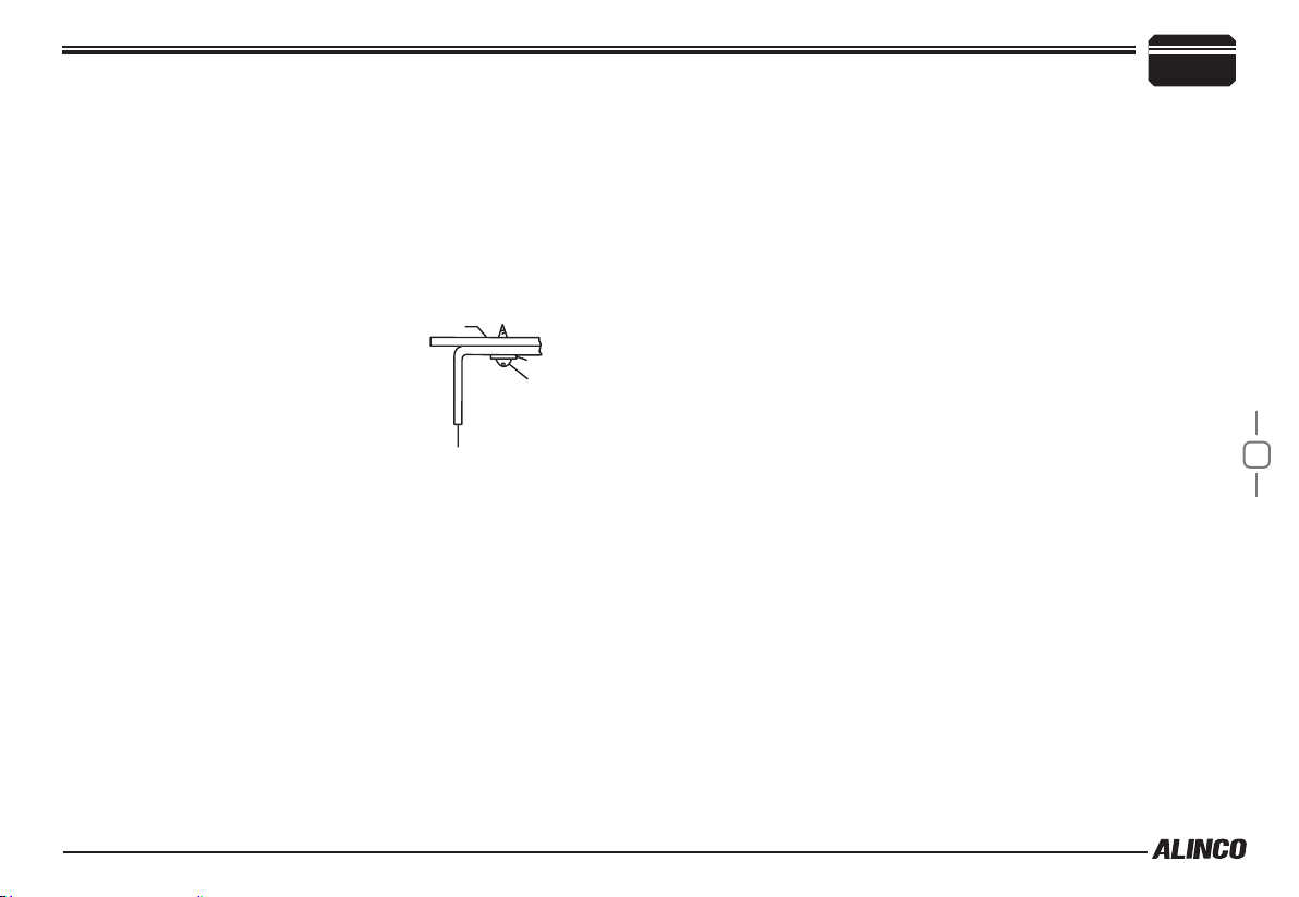
Install the mounting bracket in the vehicle using the supplied
1.
self-tapping screws (4pcs) and at washers (4pcs).
Car body
Washer (M5)
Tapping screw
(M5x20mm)
M5 Spring Washer
Mounting bracket
Initial Installation
▼
Determine the appropriate angle of the transceiver, using the 3 screw
hole positions on the side of the mounting bracket.
2
2
Position the radio , then insert and tighten the supplied
2.
gon SEMS screws.
▼
Double check that all screws are tightened to prevent vehicle
vibration from loosening the bracket or transceiver.
Caution:
Use only the provided screws
otherwise you risk damaging the
circuit board, components or fall-off
of the unit.
hexa-
Page 4

2
DC Power Cable Connection
Initial Installation
Mobile Operation
The vehicle battery must have a nominal rating of 13.8V. Never
connect the radio to a 24V battery. Be sure to use a 13.8V
vehicle battery that has sufficient current capacity. If the current
to the radio is insufficient, the display may darken during
transmission, or transmitting output power may drop excessively.
Route the DC power cable supplied with the radio directly
1.
to the vehicle's battery terminals using the shortest path from the
radio.
▼
Never use the cigarette lighter socket as a DC source.
▼
The entire length of the cable must be dressed so it is isolated from
heat, moisture, and the engine secondary(high voltage) ignition
system/cables.
After installing cable, in order to avoid the risk of damp, please use
2.
3
heat-resistant tap to tie together with fuse box. Don't forget to reinforce whole cable.
In order to avoid the risk of short circuit, please cut down connec-
3.
tion with negative (-) of battery, then connect with radio.
Confirm the correct polarity of the connections, then attach the
4.
power cable to the battery terminals; red connects to the positive (+)
terminal and black connects to the negative (-) terminal.
▼
Never remove the fuse holders from the cable.
Reconnect any wiring removed from the negative terminal.
5.
Connect the DC power cable to the radio's power supply
6.
nector.
▼
Press the connectors rmly together until the locking tab clicks.
con-
Page 5
Initial Installation
2
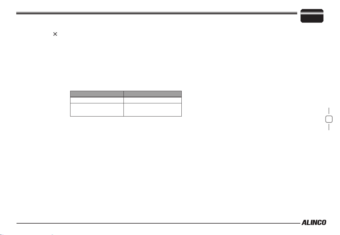
REPLACING FUSES
If the fuse blows, determine the cause, then correct the problem. After the
problem is resolved, replace the fuse. If newly installed fuses continue to
blow, disconnect the power cable and contact your dealer for assistance
Only use fuses of the specied type and rating, otherwise the radio
could be damaged.
Fuse Location Fuse Current Rating
Radio 15A
Supplied Accessory DC
power cable
20A
.
4
Page 6
2
Power supply voltage Display
After connecting the radio to the power supply, the supply voltage
can be displayed on LCD by pressing the
the
The display immediately changes as the voltage supply changes, It also
displays voltage during transmission.
The radio will return to its normal operation when the power is
turned ON/OFF or repeat above operation.
Initial Installation
[SQL / REV] key.
SQL / REV
key together with
Accessories Connections
External Speaker
If you plan to use an external speaker, choose a speaker with an
impedance of 8Ω. The external speaker jack accepts a 3.5mm (1/8")
mono (2-conductor) plug.
5
Antenna Connection
Before operating, install an efficient, well-tuned antenna. The success
of your installation will depend on the type of antenna and its correct
installation.
Use a 50Ω impedance antenna and low-loss coaxial feed-line that
has a characteristic impedance of 50Ω, to match the radio input
impedance. Coupling the antenna to the radio via feed-lines having
an impedance other than 50Ω reduces the efficiency of the antenna
system and can cause interference to nearby televisions, radio receivers
and other electronic equipment.
External speaker adopt double port BTL, please care about the connection.
Do not use the speaker that requires grounding.
Page 7

Microphone
For voice communications, connect a provided microphone into the
socket on the front of the main unit. Turn the ring firmly on the plug
until it locks. Attach the supplied microphone hanger in an appropriate
location using the screws included in the screw set.
Initial Installation
2
6
Page 8
Getting Acquainted
3
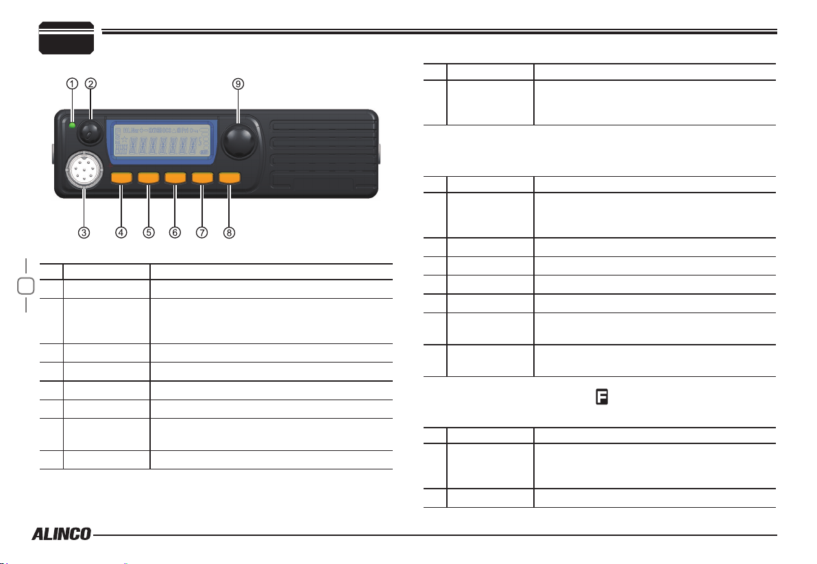
Front panel
Basic Functions
NO. KEY FUNCTION
7
1 RX
VOL Knob /
2
PWR(Power)
key
3 Mic.connector Microphone connection port
4 FUNC/SET Switches to function mode.
5 V/M/MW
6 TS/DCS/LOCK
7
CALL
8 SQL / REV Adjust Squelch level
Lights during Receiving
Rotate to adjust the volume level.
Press to switch the power on/off. (Press and
hold to turn off the power.)
Switches the CALL channel/currently displayed
channel.
NO. KEY FUNCTION
Push-button
9
rotary knob
Operations by pressing and holding the following
Rotate to change memory channels and various
settings.
Press to enter the settings.
respective keys
NO. KEY FUNCTION
VOL Knob /
2
PWR(Power)
key
4 FUNC/SET Operation is invalid.
5 V/M/MW
6 TS/DCS/LOCK
7 Operation is invalid.
CALL
8 SQL / REV
Push-button
9
rotary knob
Press [FUNC/SET] key until icon appears then press the
Press to switch the power on/off. (Press and
hold to turn off the power.)
Press and hold for 1 second to activate the
monitoring function.
Starts group scan.
following key.
NO. KEY FUNCTION
VOL Knob /
2
PWR(Power)
key
4 FUNC/SET Exits from the function mode.
Press to switch the power on/off. (Press and
hold to turn off the power.)
Page 9
NO. KEY FUNCTION
5 V/M/MW
6 TS/DCS/LOCK Exits from function mode.
7 Sets transmission output.
CALL
8 SQL / REV Sets the reverse function.
Push-button
9
rotary knob
Press [FUNC/SET] key and following key together to
Rotate to exit from function mode.
Press to set the shift function.
activate following function:
NO. KEY FUNCTION
VOL Knob /
2
PWR(Power)
key
4 FUNC/SET -
5 V/M/MW Enters clone function mode.
6 TS/DCS/LOCK
7
CALL
8 SQL / REV Switches to power supply voltage display mode.
Push-button
9
rotary knob
Rotate to adjust the volume level.
Pressing operation is invalid.
Operation is invalid.
Getting Acquainted
Operations when turning on the power while pressing the
following respective keys
NO. KEY FUNCTION
VOL Knob /
2
PWR(Power)
key
4 FUNC/SET Resets the system.
5 V/M/MW Switches operation modes.
6 TS/DCS/LOCK Operation is invalid.
7 Operation is invalid.
CALL
8 SQL / REV Operation is invalid.
Push-button
9
rotary knob
Turn on the power while pressing FUNC/SET and CALL/HL
simultaneously to reset all settings.
-
Operation is invalid.
3
8
Page 10
Getting Acquainted
3
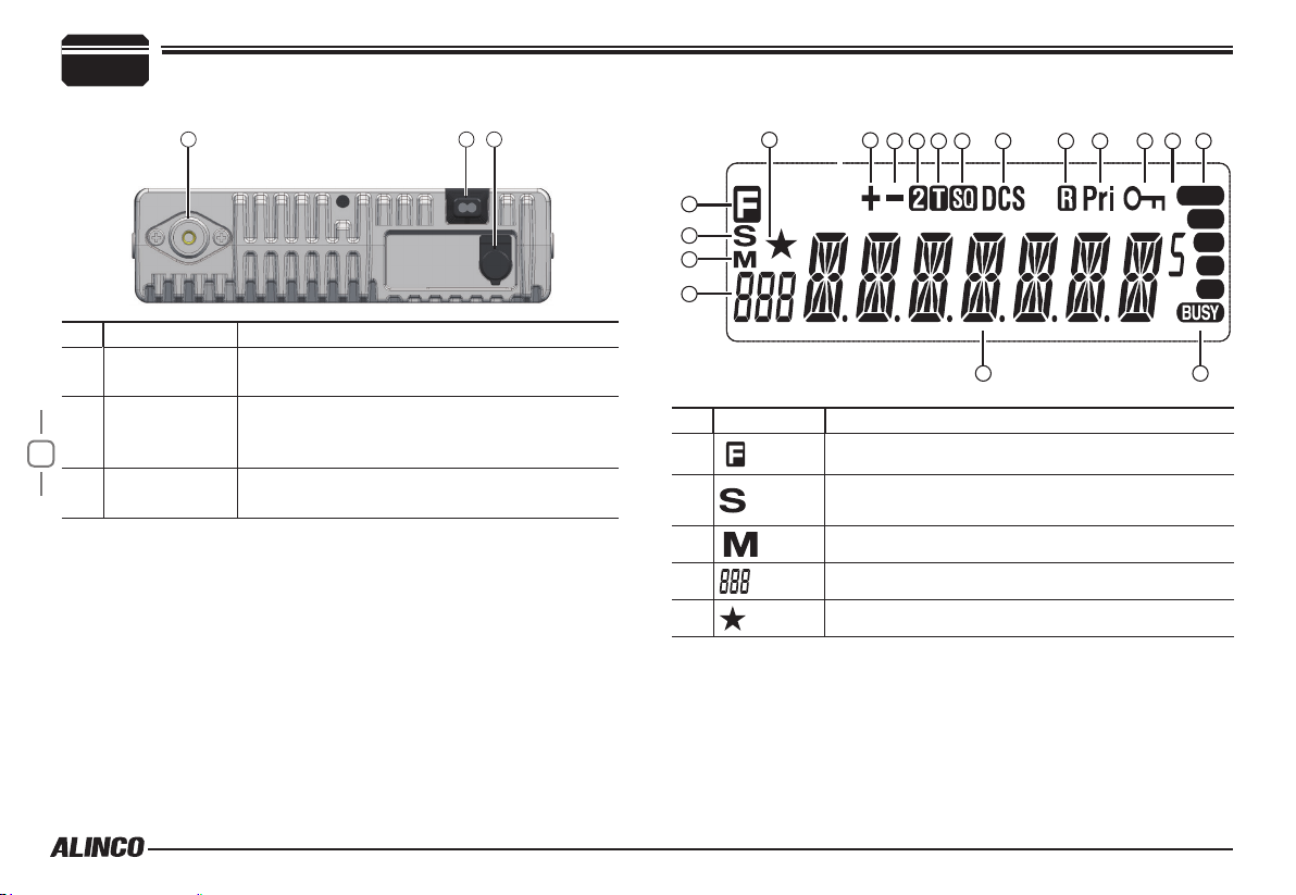
Rear panel
NO. KEY FUNCTION
Antenna
1
Connector
DATA terminal/
2
Ext.Speaker
9
Terminal
Power input
3
code
Connect an antenna.
Use for the clone function and to connect an
optional external speaker.
Connect 13.8 V DC power.
DISPLAY
3
21
1
2
3
4
5 9
11
10
14
13
12
20 21
16
15
19
17
18
NO. KEY FUNCTION
1
2
3
Lights up when function mode is ON.
Lights up when the squelch is set.
Flashes while scanning.
4 Menu number.
5
Page 11
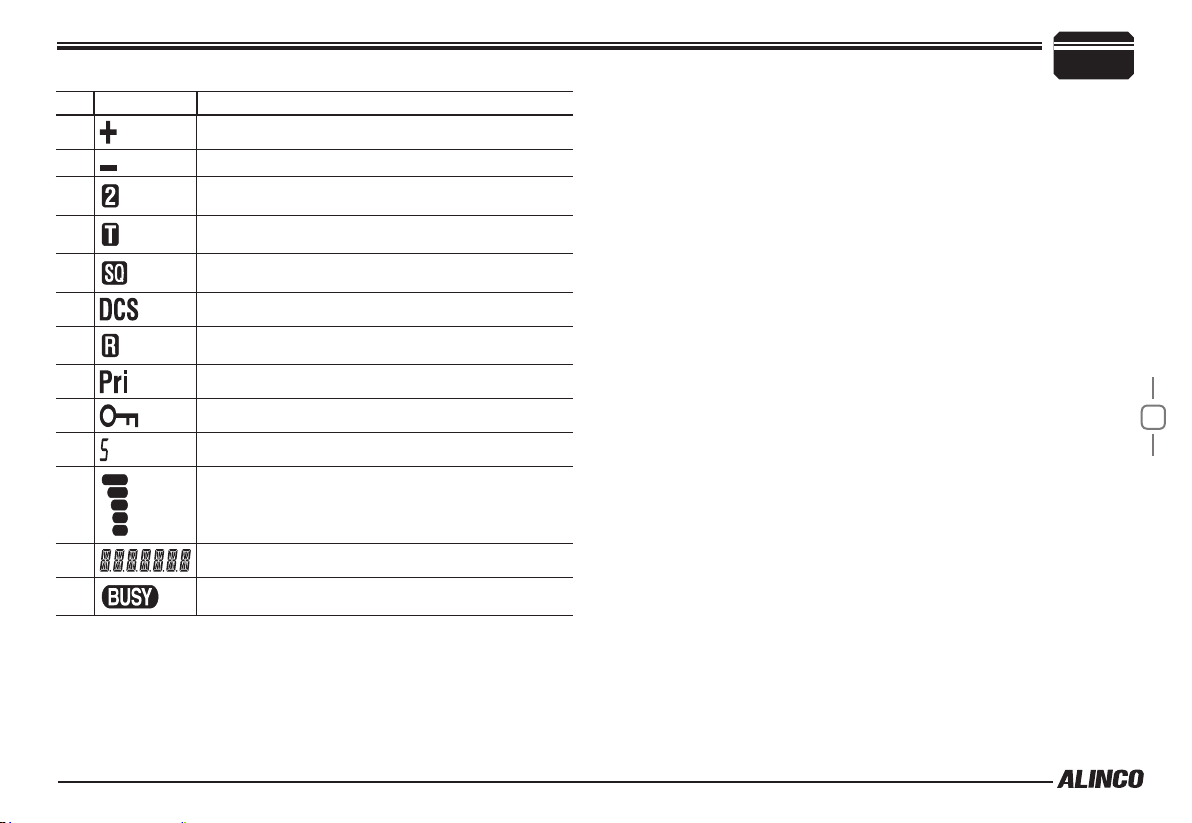
NO. KEY FUNCTION
9 Lights up when the shift direction is positive.
10
11
12 Lights up when the tone and SQ are set.
Lights up when the shift direction is negative.
Getting Acquainted
3
13
14 Lights up when CDCSS is set.
15
16
17 Lights up when the operation lock function is set.
18
19
20
21
Lights up when the SQ is set.
Lights up when the reverse function is set.
Lights up while performing priority scan.
Lights up to indicate 0.05 kHz.
Signal strength of receiving and transmitting.
Channel name or menu item.
Lights up when the squelch opens.
10
Page 12

Getting Acquainted
3
microphone
NO. KEY FUNCTION
11
UP Channel number or setting value.
1
DOWN Channel number or setting value.
2
PTT Push-To-Talk key to transmit.
3
Numerical Keys Other various oprations
4
DTMF ON/OFF Switches between DTMF and function operations.
5
LOCK Switch Locks all keys excep PTT.
6
MIC Connector Diagram(in the front view of connector)
MIC Microphone element is located.
7
Page 13

CHANNEL DISPLAY MODE
Call up and operate frequencies or settings
registered in advance. Channels set in
memory mode or with a PC application will
appear.
Rotate the push-button rotary knob or
1.
press the [UP]/[DOWN] key on the microphone to select a memory channel.
Operating Mode (Channel Display Mode)
4
12
Page 14

Basic Operations
5
Switching The Power On/Off
According to the option selected during
installation, press the VOL Knob / PWR(Power)
key or turn the ignition key to ACC or ON
position to power on. Press the VOL Knob /
PWR(Power) key for 1 seconds or turn the
ignition key to OFF position to turn off.
Adjusting The Volume
Turn the
level, counterclockwise to decrease.
13
VOL Knob / PWR(Power) key
Press and hold the [SQL / REV] key for 2 seconds to hear a
noise to set the proper audio level.
white-
Adjusting Frequency/Channel
THROUGH the dial
Under frequency (VFO) mode, you
1.
can change the current frequency to
the desired one through push-button
rotary knob; Turn clockwise to increase
frequency; turn counterclockwise to
decrease. Every click will increase or
decrease one step. Press push-button
rotary knob, the KHz order digits will be
masked. In this status, turn push-button
rotary knob or Microphone [UP]/[DOWN]
key will increase or decrease frequency
quickly by 1MHz step.
In channel display mode, you can
2.
change the current channel to the de-
clockwise to increase the audio
sired one through
forward channel, anticlockwise turn to the backward channel. In
relative Operating mode, Microphone's [UP]/[DOWN] key has the
same function for adjusting frequency and channel.
Squelch level setting
A squelch eliminates white-noise (the background noise when a signal is
not received).
Higher level settings will keep the squelch “closed” more tightly for
quieter monitoring, but weak signals will not be heard. Lower settings
allow weaker signals to “open” the squelch but noise may also cause it
to open.
• When the S-meter squelch is set to ON, the squelch will be adjusted.
• When the S-meter squelch is set to OFF, the S-meter squelch will be
adjusted.
Press [SQL / REV] key. [SQL / REV] icon
1.
appears on the display and the squelch
level will be shown at the position where
the memory number is displayed.
21 levels, between 0 and 20, are available. “0” is the lowest setting.
By rotating the main dial or by using the [UP]/[DOWN] keys on the
2.
microphone, adjust the squelch to the desired level. To return to
normal use, press [PTT] or any key on the front panel; or if there
are no operations within 5 seconds, the unit will store the setting
and will return to its original status.
push-button rotary knob
, clockwise turn to the
Page 15

The new squelch level will be stored in the CPU until another
adjustment is done.
To Receive Signals
Press the PWR key.
1.
Rotate the VOL knob to set the volume to an adequate level.
2.
While the SQL indicator is displayed, press the [SQL / REV] key,
3.
then keep rotating the knob until the noise disappears.
Select your desired frequency.
4.
When a signal is received at your desired frequency, [BUSY] will
light up and receiving sound will be heard.
The S-meter will swing according to the receiving signal strength.
Monitoring Function
This function allows you to cancel the squelch operation so that weak
signals that are below the operation level can be heard.
Press and hold the [SQL / REV] key for 1 second or more.
1.
[BUSY] will appear and the squelch operation will be canceled.
To cancel the monitoring function, press any key on the unit except
2.
for the knob.
The squelch operation will be activated again.
To Transmit Signals
Select your desired frequency.
1.
Press the [PTT] key on the microphone.
2.
The TX indicator lights red and the unit will be in transmission
mode.
Basic Operations
While pressing the [PTT] key, speak into MIC in a normal voice.
3.
Place the microphone about 5 cm away from your mouth when you
speak.
Release the [PTT] key to return to receiving mode.
Pressing the [PTT] and [DOWN] keys simultaneously will transmit a
tone call signal.
When the automatic dialer is set, pressing the [PTT] and [UP] keys
simultaneously will transmit the automatic dialer signal. (P.40)
If the [PTT] key is pressed outside of the transmission frequency
range, [OFF] will appear on the display. In this situation, signals
cannot be transmitted.
CALL mode
This is a memory mode that allows the transceiver to quickly recall
the assigned memory channel by simply pressing the [CALL/H/L] key,
regardless of the current status of the unit.
Press [CALL/H/L] key. The [C] icon appears on the display and the
1.
transceiver enters the CALL mode. In this mode, the main dial or
the [UP]/[DOWN] keys cannot change the frequency or memory
channels.
Press [CALL/H/L] key again or press [V/M/MW] key to exit CALL
2.
mode.
No scan functions are available in CALL mode.
3.
To store a desired setting in the CALL channel, follow the memory
mode programming instructions and assign your selected settings
to memory channel C. The call channel can be modied but cannot
be eliminated or hidden.
5
14
Page 16

KEY OPERATIONS
6
squelch off
Press and hold the [SQL / REV] key for 2 seconds or press MIC's
1.
key to disable squelch. Press and hold the [SQL / REV] key for
2 seconds or press MIC's
SCANNING FUNCTION
Use this function to automatically search for signals. 6 different scan
types are available in the unit.
In parameter setting mode, choose Timer mode or Busy mode to
determine the desired resuming condition. If the CTCSS(TSQ) squelch
or DCS squelch is set, the audio can be heard only when the tone/code
matches the incoming signal. Otherwise, scanning stops but no audio will
be heard. The direction of scan, upward or downward, can be changed
during the scan by rotating the main dial or pressing UP or DOWN keys
in the desired direction.
15
key again to resume squelch.
GROUP SCAN
Scan groups in memory mode or channel display mode.
Only channels stored on memory channels will be scanned. Channels 0
to 499 will be scanned.
However, C, PL/PH, PR are exceptions.
Scanning will start from channel 0, and
channels will be divided into groups according
to the group scan settings.
• When the group scanning step is set to 10
10 groups (GROUP1: Channel 0 to 9,
GROUP2: Channel 10 to 19, ...)
• When the group scanning step is set to 20
25 groups (GROUP1: Channel 0 to 19, GROUP2: Channel 20 to 39, ...)
• When the group scanning step is set to 30
17 groups (GROUP1: Channel 0 to 29,
GROUP2: Channel 30 to 59, ..., GROUP17:
Channel 480 to 499)
• When the group scanning step is set to 40
13 groups (GROUP1: Channel 0 to 39,
GROUP2: Channel 40 to 79, ..., GROUP13:
Channel 480 to 499)
• When the group scanning step is set to 50
10 groups (GROUP1: Channel 0 to 49, GROUP2: Channel 50 to 99, ...)
Press the [V/M/MW] key to enter memory mode. Or, turn off the
1.
power, then turn on the power again while pressing the [V/M/MW]
key to enter channel display mode.
Select a channel from groups within
2.
scanning range.
Press and hold the push-button rotary
3.
key to start scanning.
When scanning starts, the [S] icon will ash.
To cancel scanning, press any key except for [UP/DOWN].
4.
If there is not channel to be scanned, a beep will sound and
scanning will not start.
PRIORITY SCAN
Scan priority channels every 5 seconds in VFO mode or on the normal
display of memory mode.
Priority scan is always executed in the background when the priority scan
setting is set to ON.
When a priority channel receives a signal, the currently selected
Page 17

frequency or channel will be switched to the priority channel and the [S]
icon will ash.
Even if the frequency or channel selected before being switched has
a reception channel, the signal received by the priority channel will be
prioritized.
Tone Scan
This function automatically searches for the CTCSS tone an incoming
signal might carry. This feature is useful to search the encoding tone of
a repeater, or to communicate with a station operating in TSQ (CTCSS
squelch) mode.
Press [TS/DCS/LOCK] key to enter CTCSS decode setting mode.
1.
Press [UP]/[DOWN] key for more than 1 second but less than 2
2.
seconds to start scanning. It scans 39 tones in order.
The decimal point on the tone frequency will flash, and it stops
3.
when the matching tone is detected.
The scan won’t resume until the operation is repeated.
4.
Press any key (other than [UP]/[DOWN] keys) to exit.
5.
MEMORY Scan(channel scan)
Scans all memory channels unless Memory skip feature is selected for a
given memory.
In memory modeor channel display mode, press [V/M/MW] key for
1.
1 second to enter into channel scan.
Turn selector knob or press Microphone [UP]/[DOWN] key to
2.
change scan direction.
Press any key to exit.
3.
If there is not channel to be scanned, a beep will sound and
scanning will not start.
KEY OPERATIONS
DCS SCAN
Repeatedly press [TS/DCS/LOCK] key until LCD displays DCS icons,
then hold [TS/DCS/LOCK] key for 1 second to enter into DCS scanning.
Once nding a matching DCS code, a voice will be heard and resumes
scanning after 15 seconds.
CTCSS/DCS Encode and Decode setup
Many repeaters require a CTCSS tone or a DCS code encode setting as
a “key” to access the system, so-called “selective-calling”. Sometimes,
CTCSS or DCS decode features are used on the output of a repeater
so they can be used as a squelch. In this mode, regardless of the main
squelch status, the audio can be heard ONLY when the matching tone/
code signal is received. The combination of CTCSS squelch and DCS
function is not available; only one or the other may be used for a given
channel.The operation is available on VFO and memory mode. DealerPreprogrammed units can't operate this function manually. In the memory
mode, the setting is temporary; changing the channel or turning off the
radio will erase the setting.
Press [TS/DCS/LOCK] key. The current setting will be displayed
1.
with T/SQ/DCS icons and relative frequency/code. Press the same
key to select T/SQ/DCS setting.
The numbers (such as 88.5) represent the CTCSS frequency in
2.
Hz. When it is displayed with the
the sub-audible tone while the PTT is pressed (encode) and the
repeater access is enabled (assuming the repeater is using 88.5Hz
tone).
Press the same key again so that the
3.
icon shows up on the display. This is
the CTCSS decode frequency. This enables CTCSS squelch (or Tone Squelch,
TSQ).
icon only, the unit transmits
6
16
Page 18

KEY OPERATIONS
6
Press it again so that the 3-digit number and icon is dis-
4.
played. This is the DCS code, and it enables DCS encoding and
decoding.
For 2-4, rotate the
keys to change tone or code. Press any key ( Except FUNC / PWR /
TS / DCS, UP / DOWN keys) to enter the setting and return to original
status. The T/SQ/DCS icon will remain on the display to show the current
selective-calling status. To exit, simply use
the [TS/DCS/LOCK] key and press it until the
relative status icon T/TQ/DCS disappears.
The CTCSS encoding and decoding
frequencies may be set differently. The encode
setting frequency automatically relates to the decode setting, but decode
setting does not affect encode. The standard set of 50 different CTCSS
tones are available. DCS encode/decode cannot be separated. The list
of selectable tones and codes is shown on Appendix at the end of this
17
booklet.
Offset Direction and offset frequency setup
Repeater receives a signal(UP-LINK) on one frequency and re-transmits
on another frequency(DOWN-LINK). The difference between these two
frequencies is called the offset frequency. If the UP-LINK frequency
higher than DOWN-LINK frequency, the direction is positive, If it is lower,
the shift direction is negative.
Press [FUNC/SET] key until the icon appears on the LCD, then
1.
push-button rotary knob
or press the [UP]/[DOWN]
press push-button rotary knob, LCD displays offset direction and
offset frequency.
Repeatedly press
2.
or negative offset.
When LCD displays “ “ icon, it indicates positive offset, which
3.
means transmitting frequency higher than receiving frequency.
When LCD displays “ “ icon, it indicates negative offset, which
4.
means transmitting frequency lower than receiving frequency.
Turn
push-button rotary knob
5.
offset frequency in accordance with the step setting.
Press any key except [FUNC/SET] and [V/M/MW] key to set and
6.
nish setting.
Under channel mode, this operation can be temporarily
available.
Once the radio is turned off or switched to another channel, the
temporary setting will be erased.
KEYPAD LOCKOUT
Avoiding unintentional operation, this function will lock, all keys except
[FUNC/SET] and
Press [FUNC/SET] key until LCD displays icon, then press [TS/
1.
DCS/LOCK] key until LCD displays
function is valid.
Repeat above operation, icon disappears, indicating keypad
2.
lockout function is invalid.
push-button rotary knob
VOL Knob / PWR .
to select positive offset
or Mic’s [UP]/[DOWN] key to change
icon. Now keypad lockout
Page 19

MEMORY NAME (Alphanumeric Tag)
The memory channels stored in the memory-mode can be displayed with
an alphanumeric tag instead of the default frequency display. Program
the memory channel rst.
There are 67 characters available including A-Z, 0-9.
Rotate the push-button rotary knob or press the [UP]/[DOWN] keys
1.
on the microphone to display the menu number "2".
Select alphanumeric tag setting by rotating the main dial or press-
2.
ing the [UP]/[DOWN] keys. The display shows [A] ashing.
Rotate the main dial to select a character. Press the [V/M/MW] key.
3.
The character stops ashing and is entered.
The same ashing character appears next to it, ready for the next
4.
character to be entered. Repeat the same sequence, up to seven
characters.
To delete all characters during programming press [CALL/H/L] key.
5.
To exit after setting is done, press one of the following keys: [PTT],
6.
[FUNC/SET], [TS / DCS].
After programming, the alphanumeric tag will be displayed on the
designated channels, instead of the frequency, when in memory
mode. The memory channel number and other status icons will
also be displayed. If you wish to see the programmed frequency,
press FUNC and it will be displayed for 5 seconds. To return to the
alphanumeric display, wait 5 seconds or press any key.
Pressing any key followed by FUNC returns to normal operation,
regardless of the display status.
IMPORTANT
This function cannot be enabled without programming the
memories.
PARAMETER SETTING MODE
MEMORY DISPLAY INDICATOR
Switch the frequency display and memory NAME display when a
memory name is registered using the memory NAME function.
Rotate the push-button rotary knob or press the [UP]/[DOWN] keys
1.
on the microphone to display the menu number "3".
The current setting will appear on the display.
The default setting is "FRQ" (frequency display).
Rotate the push-button rotary knob or press the [UP]/[DOWN] keys
2.
on the microphone to change the setting.
The options are as follows.
▼
NM: Displays the memory name.
▼
FRQ: Displays the frequency.
Pressing the [FUNC/SET] key when NM is selected displays the
frequency for 5 seconds.
Press the push-button rotary knob.
3.
The unit will go back to menu mode.
BEEP
Set whether or not to output the operation sound.
Rotate the push-button rotary knob or press the [UP]/[DOWN] keys
1.
on the microphone to display the menu number "4".
The current setting will appear on the display.
The default setting is "BEEPON".
Rotate the push-button rotary knob or press the [UP]/[DOWN] keys
2.
7
20
Page 20

7
3.
DIMMER SETTING
The backlight brightness of the display can be adjusted by selecting a
level from 16 levels.
1.
21
2.
3.
PARAMETER SETTING MODE
on the microphone to change the setting.
The options are as follows.
▼
ON: Outputs the operation sound.
▼
OFF: Does not output the operation sound.
Press the push-button rotary knob.
The unit will go back to menu mode.
Rotate the push-button rotary knob or press the [UP]/[DOWN] keys
on the microphone to display the menu number "5".
The current setting will appear on the display.
The default setting is [LAMP.7].
Rotate the push-button rotary knob or press the [UP]/[DOWN] keys
on the microphone to change the setting.
The options are as follows.
▼
LAMPIN: Darkest
▼
LAMP.1 to LAMP.14: Bigger numbers for brighter backlight.
▼
LAMPIN: Brightest
Press the push-button rotary knob.
The unit will go back to menu mode.
AUTOMATIC BACK LIGHT
When pressing any key on the unit, the backlight brightness becomes
brightest for a few seconds. Set how many seconds you want to make
the backlight brightest.
Rotate the push-button rotary knob or press the [UP]/[DOWN] keys
1.
on the microphone to display the menu number "6".
The current setting will appear on the display.
The default setting is [3] (seconds).
Rotate the push-button rotary knob or press the [UP]/[DOWN] keys
2.
on the microphone to change the setting.
The options are as follows.
▼
OFF:
Pressing any key on the unit does not make the backlight
brightness brightest.
▼
3:
Pressing any key on the unit makes the backlight brightness
brightest for 3 seconds.
▼
5:
Pressing any key on the unit makes the backlight brightness
brightest for 5 seconds.
▼
7:
Pressing any key on the unit makes the backlight brightness
brightest for 7 seconds.
Press the push-button rotary knob.
3.
The unit will go back to menu mode.
Page 21

Time-Out-Timer
The TOT feature is popular in repeater systems. It prohibits the users
from transmitting on the repeater after a certain period of time has
elapsed. By setting this function and activating it according to the
repeaters’ requirement, the radio alerts the user by a beep 5 seconds
prior to time-out.
When the time is expired, transmitting stops and the radio
automatically returns to receiving mode. This avoids the repeater going
into its TOT mode. Until the PTT is released once and pressed again, the
radio will not transmit.
Rotate the push-button rotary knob or press the [UP]/[DOWN] keys
1.
on the microphone to display the menu number "7".
The current setting will appear on the display.
The default setting is [TOT .OFF].
Rotate the push-button rotary knob or press the [UP]/[DOWN] keys
2.
on the microphone to change the setting.
The options are as follows.
▼
OFF: Does not set the time out timer.
▼
30 (sec) to 450 (sec) (15 steps in 30 second increments):
Automatically switches to receiving mode after the set time has
elapsed.
Press the push-button rotary knob.
3.
The unit will go back to menu mode.
PARAMETER SETTING MODE
TOT Penalty
When the transmission is shut down in the TOT mode, this function
prohibits another transmission for a selected time period.
Rotate the push-button rotary knob or press the [UP]/[DOWN] keys
1.
on the microphone to display the menu number "8".
The current setting will appear on the display.
The default setting is [TP .OFF].
Rotate the push-button rotary knob or press the [UP]/[DOWN] keys
2.
on the microphone to change the setting.
The options are as follows.
▼
OFF: Does not set the TOT penalty time.
▼
1 (sec) to 15 (sec) (15 steps in 1 second increments):
Sets the transmission delay time when transmission is nished
by the time out timer.
Press the push-button rotary knob.
3.
The unit will go back to menu mode.
Auto Power OFF
This feature will automatically shut off the radio . It is useful for
mobile operation to avoid draining the car battery. If there is no activity or
use of the radio, it will turn off automatically after 30 minutes followed by
a beep sound.
Rotate the push-button rotary knob or press the [UP]/[DOWN] keys
1.
on the microphone to display the menu number "9".
The current setting will appear on the display.
The default setting is [APO OFF].
7
22
Page 22

7
2.
3.
MESSAGE DISPLAYED WHEN TRUNING ON THE POWER
Set whether or not to display the message when turning on the power.
1.
23
2.
PARAMETER SETTING MODE
Rotate the push-button rotary knob or press the [UP]/[DOWN] keys
on the microphone to change the setting.
The options are as follows.
▼
OFF: Does not set the auto power off function.
▼
10 (min) to 60 (min) (6 steps in 10 minute increments):
Automatically turns off the power after the set time has elapsed.
Press the push-button rotary knob.
The unit will go back to menu mode.
Rotate the push-button rotary knob or press the [UP]/[DOWN] keys
on the microphone to display the menu number "10".
The current setting will appear on the display.
The default setting is [MDL].
Rotate the push-button rotary knob or press the [UP]/[DOWN] keys
on the microphone to change the setting.
The options are as follows.
▼
OFF: Switches to receiving mode immediately.
▼
MDL:
Displays the device name for 2 seconds, then switches to
receiving mode.
▼
MSG:
Displays the message set in the "SETTING THE MESSAGE
DISPLAYED WHEN TRUNING ON THE POWER" chapter, then
switches to receiving mode.
Press the push-button rotary knob.
3.
The unit will go back to menu mode.
SETTING THE MESSAGE DISPLAYED WHEN TRUNING ON THE POWER
Set the message displayed when turning on the power.
Rotate the push-button rotary knob or press the [UP]/[DOWN] keys
1.
on the microphone to display the menu number "11".
Refer to the operation method of the "Memory NAME" to set the
2.
message to display.
Press the push-button rotary knob.
3.
The unit will go back to menu mode.
BCLO SETTING
Transmission can be limited depending on the receiving state. When
BCLO is set to ON, transmission can be initiated in the following
situation.
• When any signals are not input (when [BUSY] is off)
• If the tone frequency matches and the squelch opens when the tone
squelch is set
• If the code matches and the squelch opens when the DCS is set
Rotate the push-button rotary knob or press the [UP]/[DOWN] keys
1.
on the microphone to display the menu number "12".
The current setting will appear on the display.
The default setting is [BCLO.OFF].
Rotate the push-button rotary knob or press the [UP]/[DOWN] keys
2.
on the microphone to change the setting.
The options are as follows.
Page 23

▼
ON: Sets the BCLO setting to ON.
▼
OFF: Sets the BCLO setting to OFF.
Press the push-button rotary knob.
3.
The unit will go back to menu mode.
Tone-Burst Frequency
This is to access Tone-Burst repeaters which require a certain pitch of
audible tone to activate “sleeping” repeaters. Usually, a repeater system
does not require the tone once the repeater is activated.
Rotate the push-button rotary knob or press the [UP]/[DOWN] keys
1.
on the microphone to display the menu number "16".
The current setting will appear on the display.
The default setting is [TB .1750].
Rotate the push-button rotary knob or press the [UP]/[DOWN] keys
2.
on the microphone to change the setting.
The options are as follows.
▼
1750 (1750Hz), 2100 (2100Hz), 1000 (1000Hz), 1450 (1450Hz)
Press the push-button rotary knob.
3.
The unit will go back to menu mode.
DEFAULT TONE VALUE
Set the TONE value displayed by operating the [TS/DCS/LOCK] key for
the rst time after turning on the power. Select one out of 39 types of
standard tones.
Rotate the push-button rotary knob or press the [UP]/[DOWN] keys
1.
on the microphone to display the menu number "17".
The current setting will appear on the display.
PARAMETER SETTING MODE
The default setting is [T.67.0 ] (67.0Hz).
Rotate the push-button rotary knob or press the [UP]/[DOWN] keys
2.
on the microphone to change the setting.
The options are as follows.
▼
67.0Hz to 250.3Hz (See the table below).
• 250.3Hz is followed by 67.0Hz.
• 67.0Hz comes before 250.3Hz.
Press the push-button rotary knob.
3.
The unit will go back to menu mode.
DEFAULT SQ VALUE
Set the SQ value which is displayed by operating the [TS/DCS/LOCK]
key for the first time after turning on the power. Select one out of 39
types of standard tones.
Rotate the push-button rotary knob or press the [UP]/[DOWN] keys
1.
on the microphone to display the menu number "18".
The current setting will appear on the display.
The default setting is [T.67.0 ] (67.0Hz).
Rotate the push-button rotary knob or press the [UP]/[DOWN] keys
2.
on the microphone to change the setting.
The options are as follows.
▼
67.0Hz to 250.3Hz (See the table of the "DEFAULT TONE
VALUE").
7
24
Page 24

7
67.0 69.3 71.9 74.4 77.0 79.7 82.5 85.4 88.5 91.5
94.8 97.4 100.0 103.5 107.2 110.9 114.8 118.8 123.0 127.3
131.8 136.5 141.3 146.2 151.4 156.7 162.2 167.9 173.8 179.9
186.2 192.8 203.5 210.7 218.1 225.7 233.6 241.8 250.3
3.
DEFAULT DCS VALUE
Set the DCS value which is displayed by operating the [TS/DCS/LOCK]
25
key for the rst time after turning on the power. Select one out of 104
types of standard codes.
1.
2.
PARAMETER SETTING MODE
DEFAULT TONE VALUE
• 250.3Hz is followed by 67.0Hz.
• 67.0Hz comes before 250.3Hz.
Press the push-button rotary knob.
The unit will go back to menu mode.
Rotate the push-button rotary knob or press the [UP]/[DOWN] keys
on the microphone to display the menu number "19".
The current setting will appear on the display.
The default setting is [T.67.0 ] (67.0Hz).
Rotate the push-button rotary knob or press the [UP]/[DOWN] keys
on the microphone to change the setting.
The options are as follows.
▼
023 to 754 (See the table below).
DEFAULT DCS CODE
023 025 026 031 032 036 043 047 051 053
054 065 071 072 073 074 114 11 5 116 122
125 131 132 134 143 145 152 155 156 162
165 172 174 205 212 223 225 226 243 244
245 246 251 252 255 261 263 265 266 271
274 306 311 315 325 331 332 343 346 351
356 364 365 371 411 412 413 423 431 432
445 446 452 454 455 462 464 465 466 503
506 516 523 526 532 546 565 606 612 624
627 631 632 654 662 664 703 712 723 731
732 734 743 754
Page 25

• 754 is followed by 023.
• 023 comes before 754.
Press the push-button rotary knob.
3.
The unit will go back to menu mode.
AUTO-DIALER
This will automatically transmit pre-programmed DTMF tones.
To program tones in the Auto-dialer memory:
Rotate the push-button rotary knob or press the [UP]/[DOWN] keys
1.
on the microphone to display the menu number "20".
Pressing the [FUNC/SET] and [TS/DCS/LOCK] keys
simultaneously also displays the menu.
Default display is 0 on the right end of the display. Memory channel
icon displays which of the ten autodial memories (0~9) is in use.
Use [UP]/[DOWN] keys to select the desired channel.
2.
Rotate the main dial to select the rst digit, then press [TS/DCS/
3.
LOCK] key to enter. The Cursor moves toward right. Repeat sequence to complete.
Use [-] for pause. The display scrolls when the 7th digit is entered.
4.
The numbers 0 to 9, pause, * and # can be stored up to a total of
16 digits.
To check the entered digits, press FUNC then rotate the main dial
5.
while [F] icon is on.
To delete, press [CALL/H/L] key. Press PTT, V/M, MHz or [SQL /
6.
PARAMETER SETTING MODE
REV] keys to exit and return to original status.
DTMF TX SPEED
Set the tone output speed when outputting DTMF using the automatic
dialer.
Rotate the push-button rotary knob or press the [UP]/[DOWN] keys
1.
on the microphone to display the menu number "21".
The current setting will appear on the display.
The default setting is [DTSP.50] (50ms).
Rotate the push-button rotary knob or press the [UP]/[DOWN] keys
2.
on the microphone to change the setting.
The options are as follows.
▼
50 (50ms), 100 (100ms), 200 (200ms)
Press the push-button rotary knob.
3.
The unit will go back to menu mode.
DTMF PAUSE TIME
Set the pause time when outputting DTMF using the automatic dialer.
Rotate the push-button rotary knob or press the [UP]/[DOWN] keys
1.
on the microphone to display the menu number "22".
The current setting will appear on the display.
The default setting is [DTP.500] (500ms).
Rotate the push-button rotary knob or press the [UP]/[DOWN] keys
2.
on the microphone to change the setting.
The options are as follows.
▼
100 (100ms) to 2000 (2000ms) (20 steps in 100ms increments)
7
26
Page 26

7
3.
DTMF MONITOR
Set whether or not to output tones and tone calls output using the
automatic dialer from the speaker of the unit.
1.
2.
27
3.
Scan Type
This is to select the scan resume condition. TIMER setting allows the
radio to resume scanning after 5 seconds, regardless of the signal
receiving status. BUSY setting resumes scanning when the received
signal is gone. The scan mode is explained later.
PARAMETER SETTING MODE
Press the push-button rotary knob.
The unit will go back to menu mode.
Rotate the push-button rotary knob or press the [UP]/[DOWN] keys
on the microphone to display the menu number "23".
The current setting will appear on the display.
The default setting is [DTM.ON].
Rotate the push-button rotary knob or press the [UP]/[DOWN] keys
on the microphone to change the setting.
The options are as follows.
▼
ON:
Outputs tones and tone calls output using the automatic dialer
from the speaker of the unit.
▼
OFF:
Does not output tones and tone calls output using the automatic
dialer from the speaker of the unit.
Press the push-button rotary knob.
The unit will go back to menu mode.
Rotate the push-button rotary knob or press the [UP]/[DOWN] keys
1.
on the microphone to display the menu number "24".
The current setting will appear on the display.
The default setting is [SCAN.TMR].
Rotate the push-button rotary knob or press the [UP]/[DOWN] keys
2.
on the microphone to change the setting.
The options are as follows.
▼
TMR: Activates the timer scan.
▼
BSY: Activates the busy scan.
Press the push-button rotary knob.
3.
The unit will go back to menu mode.
SCANNING STOP TIME -TMR
From "Switching the Scanning Type", select "Timer scan" to set the
duration of time before switching to the next channel when receiving a
signal.
Rotate the push-button rotary knob or press the [UP]/[DOWN] keys
1.
on the microphone to display the menu number "25".
The current setting will appear on the display.
The default setting is [ST-T.5] (5sec).
Rotate the push-button rotary knob or press the [UP]/[DOWN] keys
2.
on the microphone to change the setting.
The options are as follows.
▼
3 (sec) to 10 (sec) (8 steps in 1 second increments)
Press the push-button rotary knob.
3.
The unit will go back to menu mode.
Page 27

SCANNING STOP TIME -BSY
From "Switching the Scanning Type ", select "Busy scan" to set the
duration time before switching to the next channel after stopping
receiving a signal.
Rotate the push-button rotary knob or press the [UP]/[DOWN] keys
1.
on the microphone to display the menu number "26".
The current setting will appear on the display.
The default setting is [ST-B.5] (5sec).
Rotate the push-button rotary knob or press the [UP]/[DOWN] keys
2.
on the microphone to change the setting.
The options are as follows.
▼
OFF (0sec) to 10 (10sec) (11 steps in 1 second increments)
Press the push-button rotary knob.
3.
The unit will go back to menu mode.
TONE SEARCH SCANNING SPEED
Set the scanning speed to search a tone frequency from the incoming
tone signal.
Rotate the push-button rotary knob or press the [UP]/[DOWN] keys
1.
on the microphone to display the menu number "27".
The current setting will appear on the display.
The default setting is [SS-T.FA].
Rotate the push-button rotary knob or press the [UP]/[DOWN] keys
2.
on the microphone to change the setting.
The options are as follows.
▼
FA: Searches fast.
PARAMETER SETTING MODE
▼
SLW: Searches slowly.
Press the push-button rotary knob.
3.
The unit will go back to menu mode.
DCS SCANNING SPEED
Set the scanning speed to search a DCS code from the incoming DCS
signal.
Rotate the push-button rotary knob or press the [UP]/[DOWN] keys
1.
on the microphone to display the menu number "28".
The current setting will appear on the display.
The default setting is [SS-D.FA].
Rotate the push-button rotary knob or press the [UP]/[DOWN] keys
2.
on the microphone to change the setting.
The options are as follows.
▼
FA: Searches fast.
▼
SLW: Searches slowly.
Press the push-button rotary knob.
3.
The unit will go back to menu mode.
PRIORITY SCAN SETTING
Set whether or not to check every 5 seconds whether the priority channel
receives a signal or not.
Rotate the push-button rotary knob or press the [UP]/[DOWN] keys
1.
on the microphone to display the menu number "29".
The current setting will appear on the display.
The default setting is [PRISOFF].
7
28
Page 28

7
2.
3.
29
MEMORY CHANNEL SCANNING SETTING
Set whether to skip programmed channels or scan only programmed
channels when scanning memory channels.
1.
2.
PARAMETER SETTING MODE
Rotate the push-button rotary knob or press the [UP]/[DOWN] keys
on the microphone to change the setting.
The options are as follows.
▼
ON:
Checks every 5 seconds whether the priority channel receives a
signal or not.
▼
OFF:
Does not check whether the priority channel receives a signal or
not.
If there is no priority channel, ON cannot be selected.
Press the push-button rotary knob.
The unit will go back to menu mode.
Rotate the push-button rotary knob or press the [UP]/[DOWN] keys
on the microphone to display the menu number "30".
The current setting will appear on the display.
The default setting is [SCHSKIP].
Rotate the push-button rotary knob or press the [UP]/[DOWN] keys
on the microphone to change the setting.
The options are as follows.
▼
SKIP: Scans skipping programmed memory channels.
▼
ONLY: Scans only programmed memory channels.
Press the push-button rotary knob.
3.
The unit will go back to menu mode.
GROUP SCANNING STEP
Set the channel step for group scanning.
Rotate the push-button rotary knob or press the [UP]/[DOWN] keys
1.
on the microphone to display the menu number "31".
The current setting will appear on the display.
The default setting is [GSTP.20].
Rotate the push-button rotary knob or press the [UP]/[DOWN] keys
2.
on the microphone to change the setting.
The options are as follows.
▼
10, 20, 30, 40, 50
Press the push-button rotary knob.
3.
The unit will go back to menu mode.
Page 29

BEAT SHIFT
Set whether or not to shift the frequency when the multiple of clock
frequency is the receiving frequency.
Rotate the push-button rotary knob or press the [UP]/[DOWN] keys
1.
on the microphone to display the menu number "33".
The current setting will appear on the display.
The default setting is [BS OFF].
Rotate the push-button rotary knob or press the [UP]/[DOWN] keys
2.
on the microphone to change the setting.
The options are as follows.
▼
ON:
Shifts the frequency when the multiple of clock frequency is the
receiving frequency.
▼
OFF:
Does not shift the frequency even when the multiple of clock
frequency is the receiving frequency.
Press the push-button rotary knob.
3.
The unit will go back to menu mode.
PARAMETER SETTING MODE
TUNING CONTROL
Set whether or not to allow operations for the push-button rotary knob
and [UP]/[DOWN] keys on the microphone when the operation lock
function is set.
Rotate the push-button rotary knob or press the [UP]/[DOWN] keys
1.
on the microphone to display the menu number "34".
The current setting will appear on the display.
The default setting is [TCTRON].
Rotate the push-button rotary knob or press the [UP]/[DOWN] keys
2.
on the microphone to change the setting.
The options are as follows.
▼
ON:
Allows to operate the push-button rotary knob and [UP]/[DOWN]
keys on the microphone when the operation lock function is set.
▼
OFF:
Does not allow to operate the push-button rotary knob and
[UP]/[DOWN] keys on the microphone when the operation lock
function is set.
Press the push-button rotary knob.
3.
The unit will go back to menu mode.
S-METER SQUELCH
Set whether to use the noise squelch or RSSI value to display the S-meter
signal.
Rotate the push-button rotary knob or press the [UP]/[DOWN] keys
1.
on the microphone to display the menu number "35".
7
30
Page 30

7
2.
3.
31
SQUELCH HANG TIME
Set the duration of time before switching to MUTE-CLOSE state after
stopping receiving a signal when the S-meter is set to ON.
1.
2.
3.
PARAMETER SETTING MODE
The current setting will appear on the display.
The default setting is [S-M .OFF].
Rotate the push-button rotary knob or press the [UP]/[DOWN] keys
on the microphone to change the setting.
The options are as follows.
▼
ON:
Uses the RSSI value to display the S-meter signal.
▼
OFF:
Uses the noise squelch to display the S-meter signal.
Press the push-button rotary knob.
The unit will go back to menu mode.
Rotate the push-button rotary knob or press the [UP]/[DOWN] keys
on the microphone to display the menu number "36".
The current setting will appear on the display.
The default setting is [S-HT.OFF].
Rotate the push-button rotary knob or press the [UP]/[DOWN] keys
on the microphone to change the setting.
The options are as follows.
▼
OFF (0ms) to 900 (900ms) (10 steps in 100ms increments)
Press the push-button rotary knob.
The unit will go back to menu mode.
Page 31

In this chapter, operations shown with is available to all units, is subject
to dealer-programming or restrictions. Some of features may be functional in
memory mode temporary, but the setting will return to the initial parameters
after changing channel or turned off the unit.
DOWN
PTT
Lock Switch
You can operate the radio by keypad or input desired frequency
or channel through the EMS-74 microphone. Keypad operations may be
blocked for dealer-programmed units.
UP
MIC
Numeric Keys
DTMF ON/OFF
Microphone Operation
Keypad Lock
Pull down the slide switch to lock position, The lamp is turned off and all
of keypads is not work except PTT switch.
Transmitting DTMF By Microphone KeyPAD
Slide DTMF key to DTMF position, press and hold the [PTT] key,
transmitting the desired DTMF signaling by the numeric key directly.
The keypad operation is suspended in DTMF position.
Function Setup By Microphone Keypad
Squelch off:In standby, press
icon ashed in LCD, Press again to enable squelch and the
icon disappears.
key, the squelch is disabled when
8
32
Page 32

9
This feature will copy the programmed data and parameters in the master unit to slave units. It copies the parameters and memory program settings.
Cable Clone
Connection
Make a cable using 3.5 mm stereo-mini plugs as shown below. Make a master unit by setting and programming it as desired. Turn off both units.
Connect the cable between the DATA jacks on both master and slave. Turn both radios on after the connection is made.
33
[Setting: Slave side]
Go to receive mode (VFO or Memory). Avoid using 9600bps data reception.
1.
When it receives the clone data, LD*** shows up on the display.
2.
When the transmission is successfully nished, the display will show [PASS].
3.
Turn off the power. Disconnect the cable and repeat the sequence to clone the next slave unit.
4.
[Setting: Master side]
Press [CALL/H/L] key with [FUNC/SET] key pressed. CLONE will be displayed and the radio enters the clone mode.
1.
Press PTT. SD*** will be displayed and it starts sending the data into the slave unit.
2.
[PASS] will appear on the display when the data is successfully transmitted.
3.
The master radio may stay turned on for the next clone. Turn off the unit to exit from the clone mode.
4.
If the data is not successfully transmitted, turn off both units, make sure the cable connection is correct and repeat the entire operation from the
beginning. If you quit the operation in condition that the clone is incompleted please reset the slave unit.
Page 33

Default Setting after Resetting DR-B185HT
DR-B185HT
Memory channel
Offset direction
Offset frequency 600KHz TOT OFF
Channel step 12.5KHz APO OFF
CTCSS encode and decode
CTCSS frequency 88.5Hz
0-499 -
-
-
DCS encode
and decode
Output power HI
Key-lock setting OFF
LCD color Orange
-
- -
Optional functions will be basically deativated and programmed values
are erased.
Maintenance
Trouble Shooting
Problem Possible Causes and Potential Solutions
(a) Power is on, nothing
appears on Display.
(b) Fuse is blown.
(c) Display is too dim. Set the LCD backlight parameter properly.
(d) No sound comes from
speaker.
(e) Key and Dial do not
function.
(i) Rotating Dial will not
change memory channel.
(g) [PTT] key is pressed but
doesn't transmit.
+ and - polarities of power connection
are reversed. Connect red lead to plus
terminal and black lead to minus terminal of
DC power supply.
Check and solve problem resulting in blown
fuse and replace fuse with a new one.
• Squelch level too hight. Decrease squelch level.
• Selective-calling like TSQ activated. Press
[Moni] key to monitor.
Key-lock function is activated. Cancel Key-lock
function.
Transceiver is in CALL mode. Press
• Microphone connection is poor. Connect
microphone properly.
• Antenna connection is poor. Connect antenna
properly.
10
.
Please contact your dealer when a technical assistanc may be
necessary.
34
Page 34

11
Specifications DR-B185T
General
Frequency Range VHF: 136-173.995MHz
Number of Channels
Channel Spacing
Channel step
Operating Voltage 13.8V DC ±15%
Squelch
Frequency Stability ±2.5ppm
Operating Temperature
Dimensions(WxHxD) 164 (W) x 44 (H) x 183.6 (D)mm
35
Weight about 1.5Kg
Specications are subject to change without notice due to advancements in
technology.
500 channels
12.5KHz
5KHz, 6.25KHz, 8.33KHz, 10KHz, 12.5KHz,
Carrier/CTCSS/DCS/5Tone/2Tone/DTMF
-10°C~+60°C
Receiver (TIA-603 standard testing )
Sensitivity
(12dB Sinad)
Adjacent Channel
Selectivity
Intermodulation ≥60dB
Spurious Rejection ≥70dB
Audio Response +1~-3dB(0.5 - 2.5 KHz)
Hum & Noise ≥40dB
Audio distortion ≤5%
Audio power output >2W@10%
≤0.35μV
≥60dB
Page 35

39 groups CTCSS Tone Frequency(Hz)
67.0 69.3 71.9 74.4 77.0 79.7 82.5 85.4 88.5 91.5
94.8 97.4 100.0 103.5 107.2 110.9 114.8 118.8 123.0 127.3
131.8 136.5 141.3 146.2 151.4 156.7 162.2 167.9 173.8 179.9
186.2 192.8 203.5 210.7 218.1 225.7 233.6 241.8 250.3
Appendix
groups DCS Code.
023 025 026 031 032 036 043 047 051 053
054 065 071 072 073 074 114 11 5 116 122
125 131 132 134 143 145 152 155 156 162
165 172 174 205 212 223 225 226 243 244
245 246 251 252 255 261 263 265 266 271
274 306 311 315 325 331 332 343 346 351
356 364 365 371 411 412 413 423 431 432
445 446 452 454 455 462 464 465 466 503
506 516 523 526 532 546 565 606 612 624
627 631 632 654 662 664 703 712 723 731
732 734 743 754
12
36
Page 36

N
: This equipment has been tested and found to comply with the limits for a Class B digital
OTE
device, pursuant to part 15 of the FCC Rules. These limits are designed to provide reasonable protection
against harmful interference in a residential installation. This equipment generates, uses and can radiate
radio frequency energy and, if not installed and used in accordance with the instructions, may cause
harmful interference to radio communications. However, there is no guarantee that interference will not
occur in a particular installation. If this equipment does cause harmful interference to radio or television
reception, which can be determined by turning the equipment off and on, the user is encouraged to try to
correct the interference by one or more of the following measures:
—Reorient or relocate the receiving antenna.
—Increase the separation between the equipment and receiver.
—Connect the equipment into an outlet on a circuit different from that to which the receiver is
connected.
—Consult the dealer or an experienced radio/TV technician for help.
This device complies with part 15 of the FCC rules. Operation is subject to the following two
conditions:
(1)thisdevicemaynotcauseharmfulinterference,and
(2) this device must accept any interference received, including interference that may cause
undesiredoperation.
Changes or modifications to this unit not expressly
approved by the party responsible for
compliancecouldvoidtheuser'sauthoritytooperatetheequipment.
 Loading...