

Page 1
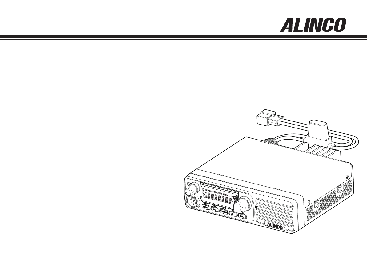
VHF FM Mobile Transceiver
DR-B185HT
DR-B185HE
Instruction Manual
Thank you for purchasing your new Alinco transceiver.
Please read this manual carefully before using the
product to ensure full performance, and keep this
manual for future reference as it contains information
on after-sales services. In case addendum or errata
sheets are included with this product, please read
those materials and keep them together with this
instruction manual for future reference.
Page 2

Introduction
Thank you very much for purchasing this excellent Alinco transceiver.
Our products are ranked among the finest in the world. This radio has
been manufactured with state of the art technology and it has been tested
carefully at our factory. It is designed to operate to your satisfaction for
many years under normal use.
Please read this manual completely from the first page to the
last, to learn all the functions the product offers. It is important to
note that some of the operations may be explained in relation to
information in previous chapters. By reading just one part of the
manual, you may risk not understanding the complete explanation
of the function.
Before transmitting
There are many radio stations operating in proximity to the frequency
ranges this product covers. Be careful not to cause interference when
transmitting around such radio stations.
■ Lightning
Please note that no car provides adequate protection of its passengers
or drivers against lightning.Therefore, Alinco will not take responsibility
for any danger associated with using its products outdoor or inside the
car during lightning.
Features
■ Output power selectable (Hi/Lo)
■ PC-programmable
■ Alphanumeric name tags
■ Sub-tone (CTCSS/DCS) Encode/Decode, DTMF/ANI
■ Various scan modes, Key lock, Wide/Narrow operations
and more at NO extra costs.
Copyright 2014 All rights reserved. NO part of this document
may be reproduced, copied, translated or transcribed in any
form or by any means writhout the prior written permission of
Alinco.Inc, Osaka, Japan, English Edition Printed in China.
Page 3
NOTICE / Compliance Information Statement
This equipment has been tested and found to comply with the limits for
a Class B digital device, pursuant to part 15 of the FCC Rules. These
limits are designed to provide reasonable protection against harmful
interference in a residential installation.
This equipment generates, uses, and can radiate radio frequency energy
and, if not installed and used in accordance with the instruction manual,
may cause harmful interference to radio communications. However, there
is no guarantee that interference will not occur in a particular installation.
If this equipment does cause harmful interference to radio or television
reception, which can be determined by turning the equipment off and on,
the user is encouraged to try to correct the interference by one or more of
the following measures:
• Reorient or relocate the receiving antenna.
• Increase the separation between the equipment and receiver.
• Connect the equipment into an outlet on a circuit different from that
to which the transceiver is connected.
• Consult the dealer or an experienced radio/TV technician for help.
Tested to Comply
WIth FCC Standards
FOR HOME OR OFFICE USE
Information in this document is subject to change without notice or
obligation. All brand names and trademarks are the property of their
respective owners. Alinco cannot be liable for pictorial or typographical
inaccuracies. Some parts, options and/or accessories are unavailable in
certain areas. Changes or modications not expressly approved by the
party responsible for compliance could void the user’s authority to operate
the equipment.
VHF FM mobile transceiver DR-B185HT
This device complies with Part 15 of the FCC Rules. Operation is subject
to the following two conditions: (1) This device may not cause harmful
interference, and (2) this device must accept any interference received,
including interference that may cause undesired operation.
Conformity Information
Alinco, Inc. Electronics Division hereby declare on our sole responsibility that
the product(s) listed below comply the essential requirements of the Directive
1999/5/EC, The council of 3/99/99 on Radio Equipment and Telecommunication
Terminal Equipment and the mutual recognition of their conformity and with
the provisions of Annex, after having performed the required measurements at
Notified Bodies per Standards, and relative certificate(s) or document(s) can be
reviewed at http://www.alinco.com/Ce/
VHF FM mobile transceiver DR-B185HE
144.000~145.995 MHz
This device is authorized for use in all EU and EFTA member states. An operator's
license is required for this device.
Check with your local waste officials for details on recycling or proper disposal
in your area.
Manufacturer:
ALINCO,Inc. Electronics Division
Yodoyabashi Dai Bldg 13F, 4-4-9, Koraibashi, Chuo-ku, Osaka
541-0043 JAPAN
Page 4
WARNING
To prevent any hazard during operation of Alinco’s radio product, in this
manual and on the product you may nd symbols shown below. Please
read and understand the meanings of these symbols before starting to
use the product.
Danger
Alert
Caution
This symbol is intended to alert the user to an immediate
danger that may cause loss of life and property if the
user disregards the warning.
This symbol is intended to alert the user to a possible
hazard that may cause loss of life and property if the
user disregards the warning.
This symbol is intended to alert the user a possible
hazard that may cause loss of property or injure the user
if the warning is disregarded.
ALART
Environment and condition of use:
Do not drive while handling the radio for your safety. It is
recommended that you check local trafc regulations regarding the
use of radio equipment while driving.
Some countries prohibit the operation of transceiver while driving.
Do not use this product in close proximity to other electronics
devices, especially medical ones. It may cause interference to
those devices.
Keep the radio out of the reach of children.
Alert symbol. An explanation is given.
Warning symbol. An explanation is given.
Instruction symbol. An explanation is given.
In case a liquid leaks from the product, do not touch it. It may
damage your skin.
Rinse with plenty of cold water if the liquid contacted your skin.
Never operate this product in facilities where radio products are
prohibited for use such as aboard aircraft, in airports, in ports,
within or near the operating area of business wireless stations or
their relay stations.
Use of this product may be prohibited or illegal outside of your
country. Be informed in advance when you travel.
The manufacturer declines any responsibilities against loss of
life and/or property due to a failure of this product when used to
perform important tasks like life-guarding, surveillance, and rescue.
Page 5
WARNING
Do not use multiple radios in very close proximity. It may cause
interference and/or damage to the product(s).
The manufacturer declines any responsibilities against loss of life
and property due to a failure of this product when used with or as a
part of a device made by third parties.
Use of third party accessory may result in damage to this product.
It will void our warranty for repair.
Handling this product:
Be sure to reduce the audio output level to minimum before using
an earphone or a headset. Excessive audio may damage hearing.
Do not open the unit without permission or instruction from the
manufacturer.
Unauthorized modification or repair may result in electric shock,
re and/or malfunction.
Do not operate this product in a wet place such as shower room. It
may result in electric shock, re and/or malfunction.
Do not place conductive materials, such as water or metal in close
proximity to the product. A short-circuit to the product may result in
electric shock, re and/or malfunction.
Do not touch the heatsink (on/around the unit mostly found on
mobile-base units) as it may become very hot during/after the
operation that may risk burn your skin.
About power-supply:
Use only appropriate, reliable and certied power supply of correct
voltage and capacity.
Do not connect cables in reverse polarity. It may result in electric
shock, re and/or malfunction.
Do not plug multiple devices including the power-supply into a
single wall outlet. It may result in overheating and/or re.
Do not handle a power-supply with a wet hand. It may result in
electric shock.
Securely plug the power-supply to the wall outlet. Insecure
installation may result in short-circuit, electronic shock and/or re.
Do not plug the power-supply into the wall outlet if the contacts are
dirty and/or dusty.
Shortcircuiting and/or overheating may result in re, electric shock
and/or damage to the product.
Do not modify or remove fuse-assembly from the DC-cable. It may
result in re, electric shock and/or damage to the product.
Page 6
WARNING
In case of emergency:
In case of the following situation(s), please turn off the product, switch
off the source of power, then remove or unplug the power-cord. Please
contact your local dealer of this product for service and assistance.
Do not use the product until the trouble is resolved. Do not try to
troubleshoot the problem by yourself.
• When a strange sound, smoke and or strange odor comes out of
the product.
• When the product is dropped or the case is broken or cracked.
• When a liquid penetrated inside.
• When a power-cord ( including DC-cables, AC-cables and adapters)
is damaged.
For your safety, turn off then remove all related AC-lines to the
product and its accessories including the antenna if a thunderstorm
is likely.
Turn off the unit, remove the mobile antenna from its base and
keep it in the vehicle if a thunderstorm is likely.
Please read cautions regarding the lightning-protection on page 9
also.
Maintenance
Do not open the unit and its accessories. Please consult with your
local dealer of this product for service and assistance.
CAUTION
Environment and condition of use:
Do not use the product in proximity to a TV or a radio. It may cause
interference or receive interference.
Do not install in a humid, dusty or insufciently ventilated place. It
may result in electric shock, re and/or malfunction.
Do not install in an unstable or vibrating position. It may result in
electric shock, re and/or malfunction when/if the product falls to
the ground.
Do not install the product in proximity to a source of heat and
humidity such as a heater or a stove. Avoid placing the unit in
direct sunlight.
Do not modify, dismantle, incinerate, or immerse the batteries that
may be used in accessories you use with this product.
Please check your local regulations for details on recycling option
or disposal of the batteries in your area.
Page 7

About transceiver
Do not connect devices other than specied ones to the jacks and
ports on the product.
It may result in damage to the devices.
Turn off and remove the power-source (AC cable, DC cable,
battery, cigar-cable, charger adapter etc) from the product when
the product is not in use for extended period of time or in case of
maintenance.
Use a clean, dry cloth to wipe off dirt and condensation from the
surface of the product.
Never use thinner or benzene for cleaning.
About power-supply
Use only reliable power supply of specic DC output range and be
mindful of the polarity of the cables and DC jack.
Always turn off the power supply when connecting or disconnecting
the cables.
When using an external antenna, make sure that the antenna
ground is not common with the ground of the power supply.
European users: When a transceiver is powered from an external
DC power source (adapter, power supply, cigar-plug etc), make
sure that this power supply has approval to the level of IEC/EN
60950-1.
WARNING
Page 8

CONTENTS
Supplied Accessories ..........................................................1
SUPPLIED ACCESSORIES ............................................................1
MOBILE INSTALLATION .................................................................2
Initial Installation ..................................................................2
DC POWER CABLE CONNECTION ............................................... 3
POWER SUPPLY VOLTAGE DISPLAY ...........................................5
ANTENNA CONNECTION ...............................................................5
ACCESSORIES CONNECTIONS ...................................................5
FRONT PANEL ................................................................................7
BASIC FUNCTIONS ........................................................................ 7
OPERATIONS BY PRESSING AND HOLDING THE
FOLLOWING RESPECTIVE KEYS ................................................. 7
Getting Acquainted ..............................................................7
PRESS
THE FOLLOWING KEY. ..................................................................8
PRESS
ACTIVATE FOLLOWING FUNCTION: .............................................8
OPERATIONS WHEN TURNING ON THE POWER WHILE
PRESSING THE FOLLOWING RESPECTIVE KEYS .....................9
REAR PANEL ................................................................................... 9
DISPLAY .......................................................................................... 10
MICROPHONE ................................................................................ 11
Operating Modes (VFO Mode, Memory Mode, Channel
Display Mode) .......................................................................12
VFO MODE ...................................................................................... 12
MEMORY MODE .............................................................................12
CHANNEL DISPLAY MODE ............................................................14
FUNC
KEY UNTIL ICON APPEARS THEN PRESS
FUNC
KEY AND FOLLOWING KEY TOGETHER TO
Basic Operations ................................................................. 15
SWITCHING THE POWER ON/OFF ............................................... 15
ADJUSTING THE VOLUME ........................................................... 15
ADJUSTING FREQUENCY/CHANNEL THROUGH THE DIAL .......15
SQUELCH LEVEL SETTING ...........................................................15
TO RECEIVE SIGNALS ...................................................................16
MONITORING FUNCTION ..............................................................16
TO TRANSMIT SIGNALS ................................................................16
CALL MODE ....................................................................................16
KEY OPERATIONS ................................................................ 17
SCANNING FUNCTION ..................................................................17
DCS SCAN ......................................................................................19
CTCSS/DCS ENCODE AND DECODE SETUP ..............................20
HIGH/LOW POWER SWITCH ......................................................... 20
OFFSET DIRECTION SETUP .........................................................21
KEYPAD LOCKOUT ........................................................................21
REVERSE FUNCTION .................................................................... 21
PARAMETER SETTING MODE .............................................22
CHANNEL STEP SETTING .............................................................22
MEMORY NAME (ALPHANUMERIC TAG) .....................................23
MEMORY DISPLAY INDICATOR ..................................................... 23
BEEP ...............................................................................................23
DIMMER SETTING .......................................................................... 24
AUTOMATIC BACK LIGHT .............................................................. 24
TIME-OUT-TIMER ...........................................................................25
TOT PENALTY .................................................................................25
AUTO POWER OFF ........................................................................25
MESSAGE DISPLAYED WHEN TURNING ON THE POWER ........ 26
Page 9

CONTENTS
SETTING THE MESSAGE DISPLAYED WHEN TRUNING ON
THE POWER ...................................................................................26
BCLO SETTING ...............................................................................26
OFFSET FREQUENCY ...................................................................27
VFO UPPER LIMIT ..........................................................................27
VFO LOWER LIMIT .........................................................................27
TONE-BURST FREQUENCY ..........................................................28
DEFAULT TONE VALUE .................................................................. 28
DEFAULT SQ VALUE ......................................................................28
DEFAULT DCS VALUE .................................................................... 29
AUTO-DIALER .................................................................................29
DTMF TX SPEED ............................................................................30
DTMF PAUSE TIME.........................................................................30
DTMF MONITOR .............................................................................31
SCAN TYPE ..................................................................................... 31
SCANNING STOP TIME -TMR ........................................................31
SCANNING STOP TIME -BSY ........................................................31
TONE SEARCH SCANNING SPEED .............................................. 32
DCS SCANNING SPEED ................................................................ 32
PRIORITY SCAN SETTING ............................................................32
MEMORY CHANNEL SCANNING SETTING ..................................33
GROUP SCANNING STEP..............................................................33
NARROW MODE ............................................................................. 33
BEAT SHIFT ..................................................................................... 34
TUNING CONTROL .........................................................................34
S-METER SQUELCH ......................................................................34
SQUELCH HANG TIME ................................................................... 35
2TONE .............................................................................................35
2TONE RECEIVING SYSTEM ........................................................36
2TONE TRANSMISSION TYPE ......................................................36
Cable Clone ........................................................................... 37
Maintenance .......................................................................... 38
DEFAULT SETTING AFTER RESETTING DR-B185.......................38
TO RESET .......................................................................................38
TROUBLE SHOOTING .................................................................... 38
Specications DR-B185 ....................................................... 39
Page 10
1
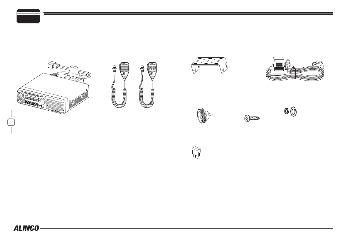
Supplied Accessories
Carefully unpack to make sure the following items are found in the package in addition to this manual:
Supplied Accessories
●Transceiver DR-B185
1
About standard microphone
Either EMS-53 or 57 comes with this product.
The instructions in this manual are based on EMS-57, therefore some
key operations may not be available to EMS-53 users.
Factory default microphones:
•DR-B185HT : EMS-57 DTMF Remote
•DR-B185HE : EMS-53 Plain
The standard accessories may vary slightly depending on the version you have purchased. Please contact your local authorized Alinco dealer should you have any
questions. Alinco and authorized dealers are not responsible for any typographical errors there may be in this manual. Standard accessories may change without
notice.
Warranty Policy: Please refer to any enclosed warranty information or contact your authorized Alinco dealer / distributor for the warranty policy.
■
In order to operate this product, a properly tuned antenna, its feedline with connectors and xing hardware are necessary. Please
●Microphone EMS-53 or
EMS-57 (with DTMF keyboard)
EMS-53 EMS-57
●Mobile Mounting Bracket ●DC Power Cable with Fuse Holder
ZFM1004
●Hardware Kit for Bracket
Black Bracket Knob
(4PCS)
ZAE1002
●Spare Fuses
(2PCS)
ZEF1001
Tapping screws
(M5X20mm)
(4PCS)
ZUA1007
S-Washer
(4PCS)
consult with your dealer for details.
Page 11

Mobile installation
The transceiver may be installed in any position in your car, where the
controls and microphone are easily accessible and it does not interfere
with the safe operation of the vehicle. If your vehicle is equipped with air
bags, be certain your radio will not interfere with their deployment. If you
are uncertain about where to mount the unit, contact your vehicle's dealer.
Install the mounting bracket in the vehicle using the supplied self-
1.
tapping screws (4pcs) and at washers (4pcs).
Car body
Washer (M5)
Tapping screw
(M5x20mm)
Initial Installation
▼
Determine the appropriate angle of the transceiver, using the 3 screw
hole positions on the side of the mounting bracket.
2
Mounting bracket
SQL
Position the transceiver, then insert and tighten the supplied
2.
hexagon SEMS screws.
▼
Double check that all screws are tightened to prevent vehicle
vibration from loosening the bracket or transceiver.
Caution:
Use only the provided screws to x the
bracket, otherwise it voids warranty and
you risk damaging the circuit board,
components or fall-off of the unit.
2
Page 12
2
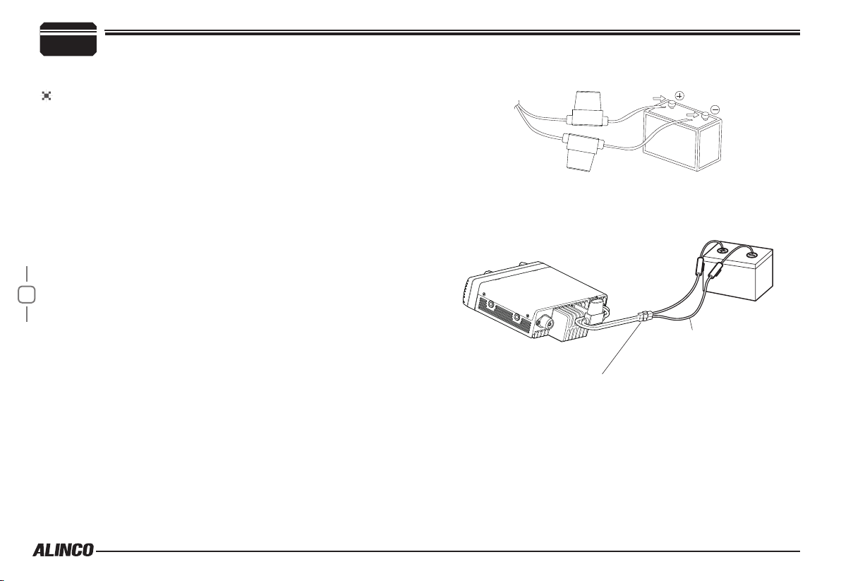
DC Power Cable Connection
Initial Installation
Reconnect any wiring removed from the negative terminal.
5.
Mobile Operation
The vehicle battery must have a nominal rating of 12V. Never connect
the transceiver to a 24V battery. Be sure to use a 12V vehicle battery
that has sufficient current capacity. If the current to the transceiver is
insufcient, the display may darken during transmission, or transmitting
output power may drop excessively.
Route the DC power cable supplied with the transceiver directly
1.
to the vehicle's battery terminals using the shortest path from the
transceiver.
▼
Never use the cigarette lighter socket as a DC source.
▼
The entire length of the cable must be dressed so it is isolated from
heat, moisture, and the engine secondary(high voltage) ignition
system/cables.
After installing cable, in order to avoid the risk of damp, please
2.
3
use heat-resistant tap to tie together with fuse box. Don't forget to
reinforce whole cable.
In order to avoid the risk of short circuit, please cut down
3.
connection with negative (-) of battery, then connect with radio.
Confirm the correct polarity of the connections, then attach the
4.
power cable to the battery terminals; red connects to the positive (+)
terminal and black connects to the negative (-) terminal.
▼
Never remove the fuse holders from the cable.
Red
Black
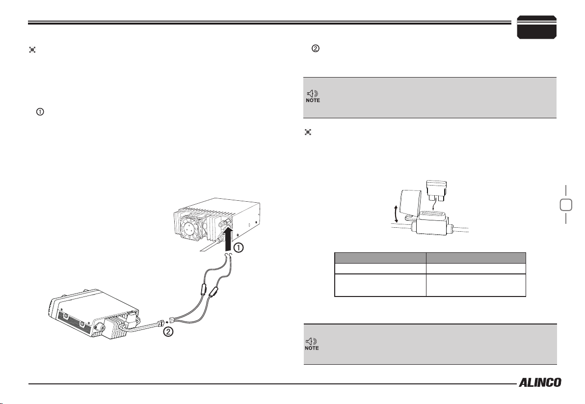
Connect the DC power cable to the transceiver's power supply
6.
connector.
▼
Press the connectors rmly together until the locking tab clicks.
DC power cable
Ext. Power jack
Page 13
Fixed Station Operation
In order to use this transceiver for xed station operation, you will need
a separate 13.8V DC power supply (not included) , Please contact local
dealer to require.
The current capacity of your power supply must be 20A or more.
Connect the DC power cable to the regulated DC power supply
and ensure that the polarities are correct. (Red: positive, Black:
negative).
▼
Never directly connect the transceiver to an AC outlet.
▼
Use the supplied DC power cable to connect the transceiver to a
regulated power supply.
▼
Do not substitute a cable with smaller gauge wires.
Initial Installation
2
Connect the transceiver’s DC power connector to the connector on
the DC power cable.
▼
Press the connectors rmly together until the locking tab clicks.
▼
Before connecting the DC power to the transceiver, be sure to
switch the transceiver and the DC power supply OFF.
▼
Do not plug the DC power supply into an AC outlet until you make
all connections.
REPLACING FUSES
If the fuse blows, determine the cause, then correct the problem. After the
problem is resolved, replace the fuse. If newly installed fuses continue to
blow, disconnect the power cable and contact your dealer for assistance
.
Regulated
power supply
Black
DC power cable with fuse holder
Red
Fuse Location Fuse Current Rating
Transceiver 20A
Supplied Accessory DC
power cable
20A
Only use fuses of the specied type and rating, otherwise the transceiver
could be damaged.
If you use the transceiver for a long period when the vehicle battery is
not fully charged, or when the engine is OFF, the battery may become
discharged, and will not have sufcient reserves to start the vehicle. Avoid
using the transceiver in these conditions.
4
Page 14

2
Power supply voltage Display
After connecting the transceiver to the power supply, the supply voltage
can be displayed on LCD by pressing the
FUNC
The display immediately changes as the voltage supply changes, It also
displays voltage during transmission.
The transceiver will return to its normal operation when the power is
turned ON/OFF or repeat above operation.
Important
5
Antenna Connection
Before operating, install an efficient, well-tuned antenna. The success
of your installation will depend on the type of antenna and its correct
installation.
Use a 50Ω impedance antenna and low-loss coaxial feed-line that
has a characteristic impedance of 50Ω, to match the transceiver input
impedance. Coupling the antenna to the transceiver via feed-lines having
an impedance other than 50Ω reduces the efficiency of the antenna
system and can cause interference to nearby televisions, radio receivers
and other electronic equipment.
Initial Installation
SQL
key together with the
key.
The range of displayed voltage is from 7V to16V DC. Because the
displayed value is estimated, please use a voltmeter when a more
precise reading is desired.
Transmitting without first connecting an antenna or other matched
load may damage the transceiver. Always connect the antenna to the
transceiver before transmitting.
All xed stations should be equipped with a lightning arrester to reduce
the risk of re, electric shock, and transceiver damage.
Accessories Connections
External Speaker
If you plan to use an external speaker, choose a speaker with an
impedance of 8Ω. The external speaker jack accepts a 3.5mm (1/8")
mono (2-conductor) plug.
External speaker adopt double port BTL, please care about the connection.
Do not use the speaker that requires grounding.
Error
Ground
Page 15
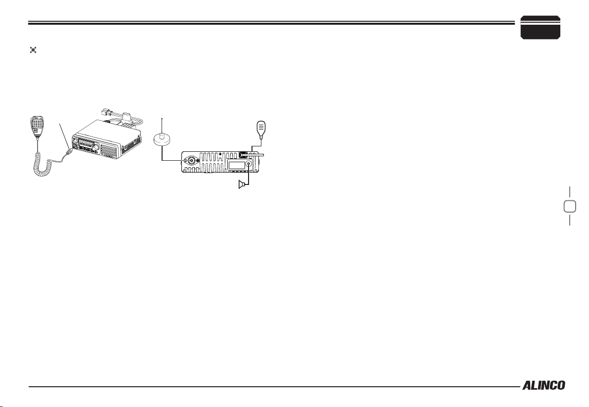
Microphone
For voice communications, connect a provided microphone into the
socket on the front of the main unit. Turn the ring rmly on the plug until it
locks. Attach the supplied microphone hanger in an appropriate location
using the screws included in the screw set.
Initial Installation
2
connector
Antenna Microphone
Microphone (EMS-53)
External speaker
6
Page 16
3
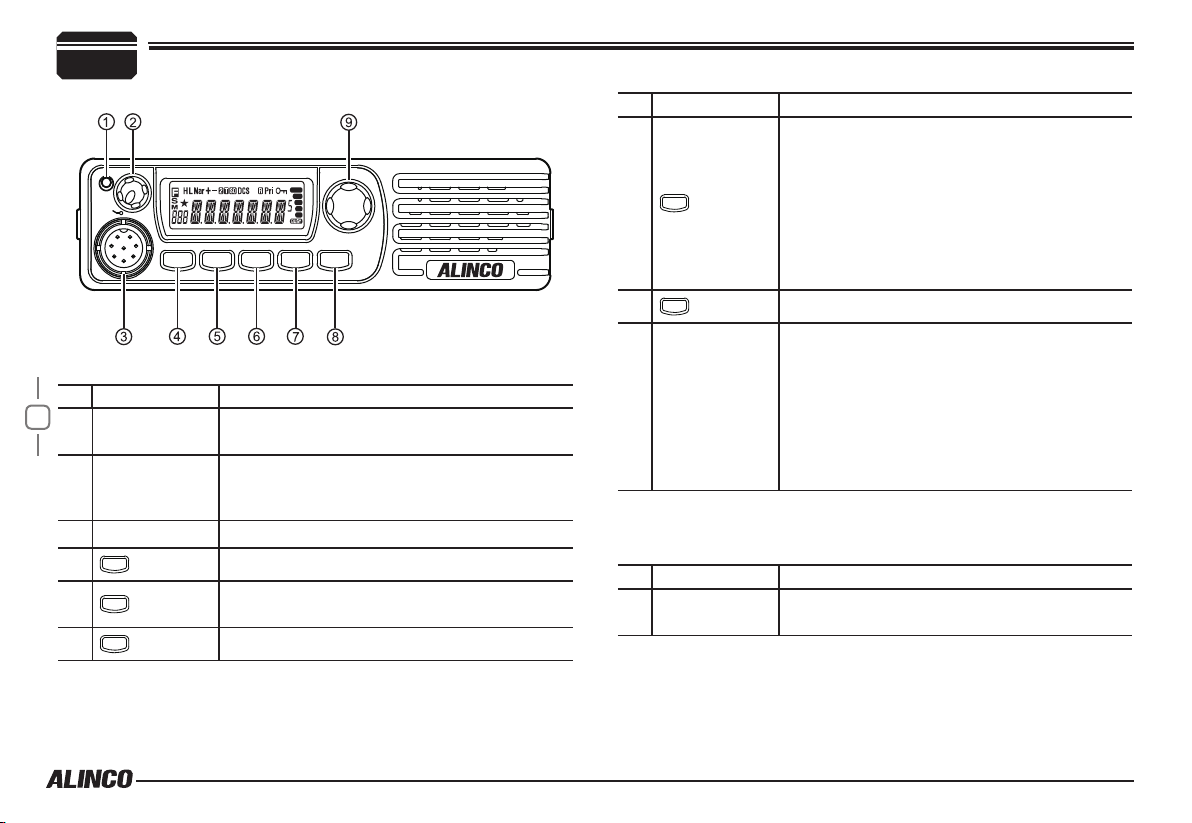
Front panel
Basic Functions
Getting Acquainted
TX
VOL
PWR
SET
FUNC
MW
LOCK
TS/DCS
V/M
H/L
CALL
REV
SQL
NO. KEY FUNCTION
7
1 TX/Busy
Lights green when channel is busy and red
when radio is transmitting
Rotate to adjust the audio level.
2 VOL knob
Press to switch the power on/off. (Press and
hold to turn off the power.)
3 Mic.connector Microphone connection port
FUNC
4
V/M
5
TS/DCS
6
Switches to function mode.
Switches between VFO mode and Channel
mode
Sets the tone squelch and DCS value
NO. KEY FUNCTION
• In VFO mode
Switches the CALL channel/VFO mode (for
the frequency being edited).
CALL
7
• In memory mode
Switches the CALL channel/memory mode.
• In channel display mode
Switches the CALL channel/currently
displayed channel.
SQL
8
Adjust Squelch level
• In VFO mode
Rotate to switch frequencies and various
settings.
9 Dial
Press to enter the settings.
• In memory mode/channel display mode
Rotate to change memory channels and
various settings.
Press to enter the settings.
Operations by pressing and holding the following
respective keys
NO. KEY FUNCTION
2 VOL knob
Press to switch the power on/off. (Press and
hold to turn off the power.)
Page 17

NO. KEY FUNCTION
• In VFO mode/memory mode
Press and hold for 2 seconds to enter
FUNC
4
parameter setting mode.
• In channel display mode
Operation is invalid.
SQL
8
Press and hold for 1 second to activate the
monitoring function. Press again to stop.
• In VFO mode
9 Dial
Starts MHz scan.
• In memory mode/channel display mode
Starts group scan.
Press
FUNC
key until icon appears then press the
following key.
NO. KEY FUNCTION
FUNC
4
V/M
5
TS/DCS
6
CALL
7
Exits from the function mode.
• In VFO mode
Stores a frequency on a memory channel.
• In memory mode/channel display mode
Set a skip channel stored on a memory
channel.
• In VFO mode/memory mode
Sets the operation lock function.
• In channel display mode
Exits from function mode.
Sets transmission output.
Getting Acquainted
NO. KEY FUNCTION
SQL
8
Sets the reverse function.
• In VFO mode/memory mode
Rotate to select a channel.
9 Dial
Press to set the shift function.
• In channel display mode
Rotate to exit from function mode.
Press to set the shift function.
Press
FUNC
key and following key together to activate
following function:
NO. KEY FUNCTION
• In VFO mode/channel display mode
5
TS/DCS
6
7
8
9 Dial
V/M
CALL
SQL
Operation is invalid.
• In memory mode
Deletes a memory channel.
• In VFO mode/memory mode
Sets the automatic dialer.
• In channel display mode
Operation is invalid.
Enters clone function mode. (Turn off to exit.)
Switches to power supply voltage display mode.
Pressing switches to the 2Tone setting.
(Pre-setting required)
3
8
Page 18

3
3
Operations when turning on the power while pressing the
Getting Acquainted
following respective keys
NO. KEY FUNCTION
FUNC
4
V/M
5
Turn on the power while pressing
to perform a full-reset. It resumes the default system settings
and erases all memory data. The deleted memory data can’t be
recalled.
9
Resets the system. Performs a System reset.
Switches to Channel display mode from VFO/
memory modes. Repeat to resume the previous
mode.
and
CALL
simultaneously
FUNC
Rear panel
3
21
NO. KEY FUNCTION
Antenna
1
Connector
2
DC power cable
DATA terminal/
3
Ext.Speaker
Terminal
About PC programming
PC programming utility software is downloadable from www.
alinco.com site. An optional ERW-7 PC cable is required.
DATA terminal is the port for PC cable connection also.
Connect an antenna.
Connect 13.8 V DC power.
20A or more current capacity is required.
Use for the clone function and to connect an
optional external speaker.
Page 19

DISPLAY
1
2
3
4
5 6 7 8 9
Getting Acquainted
3
NO. KEY FUNCTION
11
10
14
13
12
16
15
19
17
18
8
9
10
11
12
Lights up when Narrow Band is set. Turns off when
Wide Band is set.
Lights up when the shift direction is positive.
Lights up when the shift direction is negative.
Lights up when the 2-tone is set.
Lights up when the CTCSS tone encoding is set.
NO. KEY FUNCTION
1
2
Lights up when function mode is ON.
Lights up when the squelch is set.
Flashes while scanning.
Lights up when in memory mode.
3
Flashes when the selected memory channel is
empty.
4
5
6
7
Displays the memory number or menu number.
Lights up when a skip channel is stored on a
memory channel.
Lights up when HI Power is set for transmission
power.
Lights up when LO Power is set for transmission
power.
20 21
13
Lights up when the CTCSS tone squelch is set.
14 Lights up when DCS (Digital Coded Squelch) is set.
15
16
17
18
19
20
21
Lights up when the reverse function is set.
Lights up while performing priority scan.
Lights up when the operation lock function is set.
Lights up to indicate 0.05 KHz.
Signal strength of receiving and transmitting.
Displays a frequency, channel name or menu item.
Lights up when the squelch opens.
10
Page 20

3
microphone
Getting Acquainted
MIC Connector Diagram(in the front view of connector)
11
NO. KEY FUNCTION
UP Increase frequency, channel number or setting value.
1
DOWN Decrease frequency, channel number or setting value.
2
PTT Push-To-Talk key to transmit.
3
Numerical Keys Input VFO frequencies and other various oprations
4
DTMF ON/OFF Switches between DTMF and function operations.
5
LOCK Switch Locks all keys excep PTT.
6
MIC Microphone element is located inside.
7
EMS-57 EMS-53
Press and hold [UP]/[DOWN] keys until 2nd beep is heard then
release it immediately to start scanning.
Press another key to change scanning direction. Press [PTT]
to stop. Holding the key will change the frequency continuously
until the key is released.
Page 21

Operating Modes (VFO Mode, Memory Mode, Channel Display Mode)
VFO mode
VFO tuning is set as a default mode at the factory. VFO (variable
frequency oscillator) allows you to change the frequency in accordance
with the selected channel step as you rotate the main dial or by using the
[UP]/[DOWN] keys on the microphone.
VFO mode is also used to program the data to be stored in the memory
channels or to change the parameter settings of the transceiver.
Identify the current mode by checking
1.
the display.
If
or icon is NOT displayed on it,
the unit is already in the VFO mode.
Otherwise press
2.
V/M
keys or the key on the microphone
until those icons are gone.
[Change frequency by the channel step]
Rotate the dial clockwise to increase the frequency, counterclockwise
to decrease. The [UP]/[DOWN] keys on the microphone act in the same
way.
Dial
TX
VOL
PWR
LOCK
TS/DCS
REV
H/L
CALL
SQL
SET
MW
V/M
FUNC
[Change frequency by 1 MHz step]
This will enable a quick change of frequency in 1 MHz steps:
Press
dial
1.
disappear from the display.
Follow the same sequence as above to
2.
change the value.
Press [PTT] or the key on the unit.
3.
The screen will go back to the normal display.
Memory Mode
The memory mode on this transceiver provides up to 500 channels (0-
499), 1 call (quick recall ch) and a pair of program-scan “edge memory”
channels for quick, easy access to the preprogrammed frequencies with
different parameter settings.
Please note that you must program at least 1 memory channel to enter
to the memory mode. See the next page for programming procedure.
Press
1.
microphone.
indicate that the unit is in the memory mode.
Repeat to switch the mode between VFO and memory.
In memory mode, rotate the main dial or press [UP]/[DOWN] keys
2.
to change the memory channel number.
. The digits after 100 KHz will
If the unit is not operated for 5 seconds or more, the setting
procedure is canceled and the screen will go back to the normal
display.
V/M
key or the key on the
icon appears on the display to
4
12
Page 22

4
Operating Modes (VFO Mode, Memory Mode, Channel Display Mode)
[Memory programming]
Return to VFO mode by pressing
1.
or A key.
Referring to the list below for the
programmable parameters, program in the VFO mode to the
desired frequency and settings to be stored later in the memory.
When all the settings are complete, press
2.
The
, and icons appear and a
memory channel character will be
indicated on the display.
Rotate the dial or press the [UP]/
3.
[DOWN] keys to select the desired memory channel into which the
current VFO settings will be copied.
13
An empty channel is shown with a
flashing
practice to “allocate” memory channels
in order, such as 0-9 for local repeaters,
10-19 local simplex, 20-49 repeaters within the area, etc. It makes
references easier for the group scan feature explained in the
scanning function.
While icon is still on the display, press
4.
The VFO settings are copied to the memory channel and a beep
will sound twice. The memory channel can be over-written if a
previously programmed channel is selected (the memory channels
shown with a stable
Memory channel characters include C, P1, P2, PR and channel
numbers (0-499). Meanings of alphabetical characters will
follow.
V/M
icon. It may be a good
icon).
SPECIAL MEMORY CHANNELS
FUNC
key.
To program the CALL channel (quick recall) select the channel shown
with C on the display.
P1 and P2 for Program scan,and PR for Priority operation settings which
instructions will follow.
Deleting a Memory Channel
To delete a programmed channel, select
1.
it in memory mode, press
V/M
keys together while icon is on.
The memory is deleted and a beep
sounds. The
showing that this channel is now empty.
To undo delete, press
2.
this state.
However, the Undo function becomes impossible once the channel
or the mode is changed.
icon starts flashing
FUNC
V/M
key only at
and
Programmable data in the memory channel
V/M
key.
Some features will be explained later, so please read this instruction
manual thoroughly prior to programming memories.
Memory channels including 0 - 499, P1, P2, PR and CALL can store
following:
• Frequency
• Name
• Shift frequency
• Shift direction
Page 23

Operating Modes (VFO Mode, Memory Mode, Channel Display Mode)
• CTCSS tone both encode and decode
• DCS code both encode and decode
• Scan skip
• Busy Channel Lock Out setting
• Normal/Narrow FM width
P1 and P2 can be used as memory channels, but only
frequency will apply during the programmed scanning,
disregarding settings like tone and shift.
CHANNEL DISPLAY MODE
Call up and operate frequencies or settings registered in advance.
Channels set in memory mode or with a PC application will appear.
If you enter to the Channel display mode without programming any
memory channel, it will display CALL channel only.
To switch to channel display mode from VFO mode or memory
1.
mode, turn off the power, then turn on the power again while
pressing the
The unit enters the channel display
mode.
Rotate the dial or press the [UP]/
2.
[DOWN] key on the microphone to
select a memory channel.
To switch to VFO mode or memory mode from channel display
3.
mode, turn off the power, then turn on the power again while
pressing the
The unit enters the VFO mode or memory mode.
V/M
key until a beep sounds.
V/M
key until a beep sounds.
4
This mode is like a landmobile radio, allowing users for
communications only prohibiting accesses to parameter setting
modes. The reset is also prohibited in this mode, therefore, you
should resume VFO/memory mode before resetting.
14
Page 24

5
VOL Knob
Dial
Switching The Power On/Off
Basic Operations
Press the VOL knob to power on. Press the
VOL knob until it turns off.
Adjusting The Volume
Turn the
VOL knob
clockwise to increase the
audio level, counterclockwise to decrease.
Press and hold the
to set the proper audio level. Press the same key to close squelch.
Adjusting Frequency/Channel THROUGH the dial
Under VFO mode, you can change the
1.
SQL
key for 2 seconds to hear a white-
current frequency to the desired one
through dial; Turn clockwise to increase
15
frequency; turn counterclockwise to
decrease. Every click will increase
or decrease one step. Press dial, the
KHz order digits will be masked. In this
status, turn dial or Microphone [UP]/[DOWN] key will increase or
decrease frequency quickly by 1MHz step.
In memory and channel display modes, you can change the current
2.
channel to the desired one through
forward channel, anticlockwise turn to the backward channel. In
relative Operating mode, Microphone's [UP]/[DOWN] key has the
same function for adjusting frequency and channel.
Available steps are 5K, 6.25k, 10K, 12.5K, 15K, 20K, 30K and 50K.
See P.22 for selecting desired step.
TX
VOL
PWR
SET
MW
V/M
FUNC
REV
SQL
dial
, clockwise turn to the
LOCK
TS/DCS
noise
Squelch level setting
A squelch eliminates white-noise during the stand-by state (the
background noise when a signal is not received).
H/L
CALL
Higher level settings will keep the squelch “closed” more tightly for
quieter monitoring, but weak signals will not be heard. Lower settings
allow weaker signals to “open” the squelch but noise may also cause it
to open.
1.
Press
key. icon appears on the display and the squelch
SQL
level will be shown at the position where the memory number is
displayed.
16 levels, between 0 - 15, are available. “0” is the lowest setting.
By rotating the dial or by using the [UP]/[DOWN] keys on the
2.
microphone, adjust the squelch to the desired level. To return to
normal use, press [PTT] or any key on the front panel; or if there
are no operations within 5 seconds, the unit will store the setting
and will return to its original status.
Proper squelch level:
In the adjusting procedure, set it to level zero to hear the noise
first, then turn the dial to increase the level. When a noise
disappears at level 03 for example, select level 04~05 to set as
the squelch level.
Page 25

To Receive Signals
Turn on and adjust audio/squelch levels.
1.
Select your desired frequency.
2.
When a signal is received at your
desired frequency,
will light up
and receiving sound will be heard. The
S-meter will swing according to the
receiving signal strength.
Monitoring Function
This function allows you to cancel the squelch operation so that weak
signals that are below the squelch level can be heard.
Press and hold the
1.
key for 1 second or press MIC"s
SQL
key.
will appear and the squelch
opens.
To cancel the monitoring function, press
2.
[PTT] key or any key on the unit except
for the knob.
To Transmit Signals
Select your desired frequency.
1.
Press the [PTT] key on the microphone.
2.
The TX indicator lights red and starts
transmitting.
While pressing the [PTT] key, speak
3.
into MIC in a normal voice.
TX
TX
VOL
PWR
SET
MW
LOCK
H/L
CALL
TS/DCS
V/M
FUNC
Place the microphone about 5 cm away
from your mouth when you speak.
Basic Operations
5
Release the [PTT] key to return to receiving mode.
Pressing the [PTT] and [DOWN] keys simultaneously will transmit a
tone call signal.
When the auto-dialer is set, pressing the [PTT] and [UP] keys
simultaneously will transmit the auto-dialer signal set in advance.
When the 2Tone is set, select a mode other than menu mode, then
while pressing the
FUNC
key, press Dial. The icon will light up
and the transceiver will enter 2Tone mode. Press [PTT] to transmit
2Tone which is set in advance.
If the [PTT] key is pressed outside of the transmission frequency
range, [OFF] will appear on the display and warning beep sounds
until the [PTT] is released. Enter within the transmitting frequency
range to resume transmitting.
CALL mode
This is a memory mode that allows the transceiver to quickly recall the
assigned memory channel by simply pressing the
CALL
key, regardless
of the current status of the unit.
1.
Press
key. The icon appears on
CALL
the display and the transceiver enters
the CALL mode. In this mode, the main
dial or the [UP]/[DOWN] keys cannot change the frequency or
memory channels.
CALL
Press
2.
No scan functions are available in CALL mode.
3.
key again or press
V/M
key to exit CALL mode.
To store a desired setting in the CALL channel, follow the memory
mode programming instructions and assign your selected settings
to memory channel C. The call channel can be modied but cannot
be eliminated or hidden.
16
Page 26

6
SCANNING FUNCTION
Use this function to automatically search for signals. 6 different scan
types are available.
In parameter setting mode, choose Timer mode or Busy mode to
determine the desired resuming condition. If the CTCSS (TSQ) squelch
or DCS squelch is set, the audio can be heard only when the tone/code
matches the incoming signal. Otherwise, scanning stops but no audio will
be heard. The direction of scan, upward or downward, can be changed
during the scan by rotating the dial or pressing UP or DOWN keys in the
desired direction.
KEY OPERATIONS
VFO Scan
Scans all VFO channels in regard to the preset tuning step.
Enter VFO mode.
1.
17
Press and hold [UP]/[DOWN] keys for a second until the 2nd
2.
beep is heard then release it immediately to start scanning.
icon flashes while scanning. It stops at the frequency where the
incoming signal is detected, and resumes the scan according to the
selected resume condition.
Use dial or [UP]/[DOWN] keys to change the direction. Press any
3.
key (other than the [UP]/[DOWN] keys) to exit.
Program Scan
This is a type of VFO scan, but by setting the frequency range of the
VFO into P1 and P2 channels, it only scans between those frequencies.
With setting the P1 and P2 properly, up to 3 Program scan ranges will be
available.
When P1, P2 is registered
L
VFO Lower
Limit
When only P1 is registered
L
VFO Lower
Limit
When only P2 is registered
L
VFO Lower
Limit
Program the P1 and P2 memory channels as you desire in
1.
advance.
Select a frequency range that you wish to scan. Suppose you wish
2.
to monitor a range between lowest VFO frequency and P1, select
any frequency between these 2 frequencies.
Press [UP]/[DOWN] key for more than 1 second to start scanning.
3.
During this scan mode, the “P” icon appears and
P1
Program Scan
Memory1
P1
Program Scan
Memory1
P2
Program Scan
Memory2
P2
Program Scan
Memory2
U
VFO Upper
Limit
U
VFO Upper
Limit
U
VFO Upper
Limit
icon ashes.
The scanning step depends on the channel step setting value. If
you wish to scan all VFO range, don’t program P1/P2 channels.
Use dial or [UP]/[DOWN] keys to change the direction. Press any
4.
key (other than the [UP]/[DOWN] keys) to exit.
Page 27

MHz SCAN
Scan frequencies that are below 1 MHz.
For example, for scanning 144 MHz, frequencies will be scanned
repeatedly from 144.000 MHz to 144.995 MHz in accordance with the
channel step.
Press the
1.
Press and hold the dial.
2.
When scanning starts, the
1 MHz decimal point of the frequency
display will ash.
Use dial or [UP]/[DOWN] keys to change the direction. Press any
3.
key (other than the [UP]/[DOWN] keys) to exit.
V/M
key to enter VFO mode.
icon and
GROUP SCAN
Scan groups in memory mode or channel display mode.
Enough numbers of memory channel must be programmed in advance
to use this feature.
Only channels stored on memory channels will be scanned. Channels 0
to 499 will be scanned.
However, C, P1, P2, PR are exceptions.
Scanning starts from the selected memory channel number, and
channels will be divided into groups according to the group scan step
settings explained later in the set mode (menu 31).
KEY OPERATIONS
25 groups (GROUP1: Channel 0 to 19, GROUP2: Channel 20 to 39, ...)
• When the group scanning step is set to 30
17 groups (GROUP1: Channel 0 to 29, GROUP2: Channel 30 to 59, ...,
GROUP17: Channel 480 to 499)
• When the group scanning step is set to 40
13 groups (GROUP1: Channel 0 to 39, GROUP2: Channel 40 to 79, ...,
GROUP13: Channel 480 to 499)
• When the group scanning step is set to 50
50 groups (GROUP1: Channel 0 to 49, GROUP2: Channel 50 to 99, ...)
Press the
1.
then turn on the power again while pressing the
channel display mode.
Select a channel from groups within scanning range.
2.
Press and hold the dial to start
3.
scanning.
When scanning starts, the
ash.
Suppose you programmed 20 memories, set group step as 10,
select ch. 5 and start scanning, it scans between ch. 0 and ch. 9.
Use dial or [UP]/[DOWN] keys to change the direction. Press any
4.
key (other than the [UP]/ [DOWN] keys) to exit.
C,P1,P2 and PR are exceptions and can’t perform the group
scanning. A beep sounds to alert.
V/M
key to enter memory mode. Or, turn off the power,
V/M
icon will
6
key to enter
18
• When the group scanning step is set to 10
50 groups (GROUP1: Channel 0 to 9, GROUP2: Channel 10 to 19, ...)
• When the group scanning step is set to 20
Page 28

6
KEY OPERATIONS
PRIORITY SCAN
Scan priority channels every 5 seconds in VFO mode or on the normal
display of memory mode.
Priority scan is always executed in the background when the priority
scan setting is set to ON at the Menu 29 in the Set mode setting.
appears while Pri function is activated.
When a priority channel receives a signal, the
currently selected frequency or channel will be
switched to the priority channel and the
icon will ash.
Even if the frequency or channel selected before being switched has
a reception channel, the signal received by the priority channel will be
prioritized.
Tone Scan
19
This function automatically searches for the CTCSS tone an incoming
signal might carry. This feature is useful to search the encoding tone of a
repeater, or to communicate with a station operating in TSQ (CTCSS
squelch) mode.
Press the
1.
CTCSS decode setting mode.
The
Press and hold [UP]/[DOWN] keys for a second until the 2nd beep
2.
is heard then release it immediately to start scanning. It scans
39 tones in order. Use [UP]/[DOWN] key to change the scanning
direction.
The
the matching tone is detected.
TS/DCS
key until entering to the
and icons will light up.
icon will ash, and it stops when
icon
The scan won’t resume until the operation is repeated.
3.
Press any key (other than [UP]/[DOWN] keys) to exit.
4.
MEMORY Scan(channel scan)
Scans all memory channels unless Memory skip feature is selected for a
given memory.
Press the
1.
will light up and the transceiver will enter memory mode.
Press and hold [UP]/[DOWN] keys for
2.
a second until the 2nd beep is heard
then release it immediately to start
scanning.
Use dial or [UP]/[DOWN] keys to change the direction. Press any
3.
key (other than the [UP]/[DOWN] keys) to exit.
Memory channels should be programmed in advance to operate
memory scanning.
DCS SCAN
This function automatically searches for the DCS tone an incoming
signal might carry. This feature is useful to search the encoding tone of a
repeater, or to communicate with a station operating in DCS mode.
Press the
1.
The
Press and hold [UP]/[DOWN] keys for a second until the 2nd beep
2.
is heard then release it immediately to start scanning. It scans
104 tones in order. Use [UP]/[DOWN] key to change the scanning
direction.
V/M
key to select memory mode.
TS/DCS
key until entering DCS decode setting mode.
icon will light up.
Page 29

The icon will ash, and it stops when
the matching tone is detected.
Press any key (other than [UP]/[DOWN]
3.
keys) to exit.
CTCSS/DCS Encode and Decode setup
In this mode, regardless of the main squelch status, the audio can
be heard ONLY when the matching tone/code signal is received. The
combination of CTCSS squelch and DCS function is not available; only
one or the other may be used for a given channel. In the memory mode,
the setting is temporary; changing the channel or turning off the radio will
resume the original conditions.
TS/DCS
Press
1.
T/SQ/DCS setting.
The numbers (such as 88.5) represent the CTCSS frequency in
Hz. Use dial or [UP]/[DOWN] keys to select desired parameter.
When it is displayed with the
only, the unit transmits the sub-audible
tone while the PTT is pressed (encode)
and the repeater access is enabled
Press the same key again so that the
2.
and
This is the CTCSS decode frequency.
This enables CTCSS squelch (or Tone
Squelch, TSQ).
Press it again so that the 3-digit number
3.
and
the DCS code, and it enables DCS
encoding and decoding.
key. The current setting will be displayed with , ,
icons and relative frequency/code. Press the same key to select
icon
icons show up on the display.
icon is displayed. This is
KEY OPERATIONS
Press any key (Except
setting and return to original status. The
on the display to show the current selective-calling status. To exit, simply
use the
disappears.
The CTCSS encoding and decoding frequencies may be set differently.
The standard set of 39 different CTCSS tones are available. DCS
encode/decode cannot be separated. The list of selectable tones and
codes is shown on Appendix at the end of this booklet.
Press
high/low power. You may use zero (H/L) key on EMS-57 microphone
also.
H : Transmits in high power
L : Transmits in low power
TS/DCS
key and press it until the relative status icon T/TQ/DCS
HIGH/LOW Power switch
FUNC
key to display icon, then press
FUNC
, PWR,
TS/DCS
, [UP]/[DOWN] keys) to enter the
, , icon will remain
CALL
key to switch between
6
20
Page 30

6
Offset Direction setup
Repeater receives a signal(UP-LINK) on one frequency and re-transmits
on another frequency(DOWN-LINK). The difference between these two
frequencies is called the offset frequency. If the UP-LINK frequency
higher than DOWN-LINK frequency, the direction is positive, If it is lower,
the shift direction is negative.
1.
2.
3.
4.
21
KEY OPERATIONS
FUNC
Press
dial, LCD displays offset direction.
Repeatedly press the
When LCD displays icon, it indicates
positive offset, which means transmitting
frequency higher than receiving
frequency.
When LCD displays icon, it indicates
negative offset, which means
transmitting frequency lower than
receiving frequency.
Shift width(frequnecy) can be set in the parameter setting mode
at menu 13 (p.27).
key until the icon appears on the LCD, then press
FUNC
key and dial to select offset direction.
KEYPAD LOCKOUT
Avoiding unintentional operation, this function will lock all keys except
[PTT],
1.
2.
REVERSE FUNCTION
This function allows you to reverse the transmission frequency and
reception frequency while operating with offset.
1.
2.
SQL
FUNC
,
, and
VOL knob .
FUNC
Press
icon, then press
displays
function is valid.
Repeat above operation, icon disappears, indicating keypad
lockout function is invalid.
The shift offset must be set in advance on the operating
channel.
Press the
then press
icon appears and the receiving
frequency is replaced to the transmitting frequency.
To cancel the reverse function, repeat the same operation
described above.
CTCSS and DCS tones won’t be reversed even if encoding and
decoding tones are set differently.
key until LCD displays
TS/DCS
key until LCD
icon. Now keypad lockout
FUNC
key, conrm lights up,
SQL
.
Page 31

The following is the Selectable Parameters’ Menu.
Please read the following pages thoroughly prior to the
IMPORTANT
change of any parameters.
THE PARAMETERS CANNOT BE SET WITHOUT
ENTERING THE SET MODE.
PARAMETER SETTING MODE
Channel Step setting
* This menu appears only in VFO mode.
This is to select the channel step to be used in the VFO mode.
Refer to the chart below for the relation of the actual step frequency and
how it is displayed.
7
By entering the Parameter Setting mode, some of the radio’s operating
parameters can be changed to suit your application.
To use the Parameter Setting mode
FUNC
Press
1.
Setting mode.
Rotate the dial or [UP]/[DOWN] keys to select menu.
Press the dial to display “set” on the left corner of LCD. Turn the
2.
dial to select the desired value, then press it again to select another
menu.
Press any key OTHER than
3.
mode. The only exception is the Channel Tag setting which accepts
only [PTT],
Some menus appear only in certain modes or preprogramming
may be required.
key for more than 2 seconds to enter the Parameter
FUNC
key,
dial
to exit the Parameter
, and
TS/DCS
keys to exit.
FUNC
5
(5kHz)
50
(50kHz)
FUNC
Press
key until entering the Parameter setting mode.
Rotate the dial or press the [UP]/
1.
[DOWN] keys on the microphone to
display the menu number "01".
The current setting will appear on the
display.
The default setting is “5 KHz ” for DR-B185HT, "12.5 KHz" for HE
models.
Press dial to display SET, then rotate dial or press the [UP]/[DOWN]
2.
keys on the microphone to change the setting.
Press the dial to set the new value and continue, or press [PTT] to
3.
set the new value and exit from the parameter setting mode.
Be sure to set the KHz order of the frequency at even-number
such as .000, prior to change this parameter in VFO mode.
6.25
(6.25kHz)
30
(30kHz)
10
(10kHz)
20
(20kHz)
(12.5kHz)
(15kHz)
12.5
15
22
Page 32

7
MEMORY NAME (Alphanumeric Tag)
The memory channels stored in the memory-mode can be displayed with
an alphanumeric tag instead of the default frequency display. Program
the memory channel rst.
There are 48 characters available including A-Z, 0-9.
* This menu appears only in memory mode.
1.
2.
3.
4.
23
5.
6.
7.
8.
PARAMETER SETTING MODE
Program at least 1 memory channel in advance. Select the memory
channel to be Memory-named and enter to the set mode by
pressing
Rotrate the dial or press the [UP]/
[DOWN] keys on the microphone to
display the menu number "02".
Press the dial so that A appears on the
display.
Rotate the dial to select a character to
be programmed.
Press the dial again to edit next.
Press
to 7 characters can be entered.
Press [PTT],
Press
After programming, the alphanumeric tag will be displayed on the
designated channels, instead of the frequency, when in memory
mode. The memory channel number and other status icons will
also be displayed. If you wish to see the programmed frequency,
press
display, press any key.
FUNC
key.
SQL
key to correct, or
TS/DCS
FUNC
or
V/M
key to set and return to the menu mode.
FUNC
and it will be displayed. To return to the alphanumeric
If the display remains unchanged, follow the instruction of menu
3 and select NM.
CALL
key to erase all characters. Up
key to cancel operation and exit.
MEMORY DISPLAY INDICATOR
Switch the frequency display and memory name display when a memory
name is registered using the memory name function.
Rotate the dial or press the [UP]/[DOWN] keys on the microphone
1.
to display the menu number "03".
The current setting will appear on the
display.
The default setting is "FRQ" (frequency
display).
Press dial to display SET, then rotate dial or press the [UP]/[DOWN]
2.
keys on the microphone to change the setting.
The options are as follows.
▼
NM: Displays the memory name (Default).
▼
FRQ: Displays the frequency.
Regardless of the NM setting, frequency is always displayed on
channels that name tags are not programmed.
Press the dial.
3.
The unit will go back to menu mode.
BEEP
Set whether or not to sound the operation beep.
Rotate the dial or press the [UP]/
1.
[DOWN] keys on the microphone to
display the menu number "04".
The current setting will appear on the display.
The default setting is "BEEPON".
Page 33

Press dial to display SET, then rotate dial or press the [UP]/[DOWN]
2.
keys on the microphone to change the setting.
The options are as follows.
▼
ON: Beep tones sound.
▼
OFF: Beep tones don't sound.
The Time-Out Timer and transmission-related warning beep
remain always sound regardless of the beep setting.
Press the dial.
3.
The unit will go back to menu mode.
DIMMER SETTING
The backlight brightness is selectable from 16 levels.
Rotate the dial or press the [UP]/[DOWN] keys on the microphone
1.
to display the menu number "05".
The current setting will appear on the
display.
The default setting is "7".
Press dial to display SET, then rotate dial or press the [UP]/[DOWN]
2.
keys on the microphone to change the setting.
The options are as follows.
▼
LAMP.MIN: Darkest
▼
LAMP.1 to LAMP.14: Bigger numbers for brighter backlight.
▼
LAMP.MAX: Brightest
Press the dial.
3.
The unit will go back to menu mode.
PARAMETER SETTING MODE
AUTOMATIC BACK LIGHT
When pressing any key on the unit, the backlight brightness becomes
brightest for a few seconds. Set how many seconds you want to make
the backlight brightest.
Rotate the dial or press the [UP]/[DOWN] keys on the microphone
1.
to display the menu number "06".
The current setting will appear on the
display.
The default setting is "3" (seconds).
Press dial to display SET, then rotate dial or press the [UP]/[DOWN]
2.
keys on the microphone to change the setting.
The options are as follows.
▼
OFF:
Pressing any key on the unit does not make the backlight
brightness brightest.
▼
3:
Pressing any key on the unit makes the backlight brightness
brightest for 3 seconds.
▼
5:
Pressing any key on the unit makes the backlight brightness
brightest for 5 seconds.
▼
7:
Pressing any key on the unit makes the backlight brightness
brightest for 7 seconds.
Press the dial.
3.
The unit will go back to menu mode.
7
24
Page 34

7
Time-Out-Timer
The TOT feature is popular in repeater systems. It prohibits the users
from transmitting after a certain period of time has elapsed. By setting
this function and activating it the radio alerts the user by a beep 5
seconds prior to time-out.
When the time is expired, transmitting stops and the transceiver
automatically returns to receiving mode. Until the [PTT] is released once
and pressed again, the transceiver will not transmit.
1.
2.
25
3.
TOT Penalty
When the transmission is shut down in the TOT mode, this function
prohibits another transmission for a selected time period.
PARAMETER SETTING MODE
Rotate the dial or press the [UP]/[DOWN] keys on the microphone
to display the menu number "07".
The current setting will appear on the
display.
The default setting is "OFF".
Press dial to display SET, then rotate dial or press the [UP]/[DOWN]
keys on the microphone to change the setting.
The options are as follows.
▼
OFF: Does not set the time out timer.
▼
30 (sec) to 450 (sec) in 15 steps / 30 second increments:
Automatically switches to receiving mode after the set time has
elapsed.
Press the dial.
The unit will go back to menu mode.
Rotate the dial or press the [UP]/[DOWN] keys on the microphone
1.
to display the menu number "08".
The current setting will appear on the
display.
The default setting is "OFF".
Press dial to display SET, then rotate dial or press the [UP]/[DOWN]
2.
keys on the microphone to change the setting.
The options are as follows.
▼
OFF: Does not set the TOT penalty time.
▼
1 (sec) to 15 (sec) /15 steps in 1 second increments:
Sets the transmission delay time when transmission is nished
by the time out timer.
Press the dial.
3.
The unit will go back to menu mode.
Auto Power OFF
This feature will automatically shut off the transceiver. It is useful for
mobile operation to avoid draining the car battery. If there is no activity or
use of the radio, it will turn off automatically after 30 minutes followed by
a beep sound.
Rotate the dial or press the [UP]/[DOWN] keys on the microphone
1.
to display the menu number "09".
The current setting will appear on the
display.
The default setting is "OFF".
Press dial to display SET, then rotate dial or press the [UP]/[DOWN]
2.
keys on the microphone to change the setting.
Page 35

The options are as follows.
▼
OFF: Does not set the auto power off function.
▼
10 (min) to 60 (min) /6 steps in 10 minute increments:
Automatically turns off the power after the set time has elapsed.
Press the dial.
3.
The unit will go back to menu mode.
MESSAGE DISPLAYED WHEN turning ON THE POWER
Set whether or not to display the message when turning on the power.
Rotate the dial or press the [UP]/[DOWN] keys on the microphone
1.
to display the menu number "10".
The current setting will appear on the
display.
The default setting is "MDL".
Press dial to display SET, then rotate dial or press the [UP]/[DOWN]
2.
keys on the microphone to change the setting.
The options are as follows.
▼
OFF: Switches to receiving mode immediately.
▼
MDL:
Displays the "DR-B185" for 2 seconds, then switches to receiving
mode.
▼
MSG:
Displays the message set in the next chapter, then switches to
receiving mode.
Press the dial.
3.
The unit will go back to menu mode.
PARAMETER SETTING MODE
SETTING THE MESSAGE DISPLAYED WHEN TRUNING ON THE POWER
Set the message displayed when turning on the power.
Rotate the dial or press the [UP]/
1.
[DOWN] keys on the microphone to
display the menu number "11".
By refering to the Menu 2 on P.23, edit
2.
the message to display.
Press the dial.
3.
The unit will go back to menu mode.
BCLO SETTING
BCLO stands for Busy Channel Lock Out, and prohibits transmission that
may cause interferences to ongoing communications. Transmission is
possible only in the conditions:
• When the channel is free and clear (BUSY icon is not displayed).
• The CTCSS/DCS setting of receiving signal is different from the current
tone setting.
Rotate the dial or press the [UP]/[DOWN] keys on the microphone
1.
to display the menu number "12".
The current setting will appear on the
display.
The default setting is "OFF".
Press dial to display SET, then rotate dial or press the [UP]/[DOWN]
2.
keys on the microphone to change the setting.
The options are as follows.
▼
ON: Sets the BCLO setting to ON.
▼
OFF: Sets the BCLO setting to OFF.
7
26
Page 36

7
3.
OFFSET FREQUENCY
Using this function, the transmission
frequency can be shifted by the offset
frequency range set for the reception
frequency.
1.
2.
27
3.
VFO UPPER LIMIT
* This menu appears only in VFO mode.
* Not available in HE version.
This is to set the upper limit of the VFO. By setting this, dial and [UP]/
[DOWN] operation will be limited up to the programmed frequency.
PARAMETER SETTING MODE
Press the dial.
The unit will go back to menu mode.
Please refer P.20 for the shift direction (Press
dial will switch the direction).
Rotate the dial or press the [UP]/[DOWN] keys on the microphone
to display the menu number "13".
The default setting is "0.6000" (0.6MHz).
The options are 0 to 99.9950MHz in accrodance with preset
channel step.
The adjustment step depends on the step setting value.
Press the dial.
The unit will go back to menu mode.
Setting changes will not affect memory channels and
programmed scanning range.
FUNC
key then the
Rotate the dial or press the [UP]/[DOWN] keys on the microphone
1.
to display the menu number "14".
The current setting will appear on the
display.
The default setting is "174" (174MHz).
Press dial to display SET, then rotate dial or press the [UP]/[DOWN]
2.
keys on the microphone to change the setting.
The options are between 174 and 137MHz in 1MHz step.
This value should be higher than the frequency set in the next
chapter.
Press the dial.
3.
The unit will go back to menu mode.
VFO LOWER LIMIT
* This menu appears only in VFO mode.
* Not available in HE version.
Set the lower limit frequency used in VFO mode.
Setting changes will not affect memory channels and
programmed scanning range.
Rotate the dial or press the [UP]/[DOWN] keys on the microphone
1.
to display the menu number "15".
The current setting will appear on the
display.
The default setting is "136" (136MHz).
Press dial to display SET, then rotate dial or press the [UP]/[DOWN]
2.
keys on the microphone to change the setting.
Page 37

The options are between 173 and 136MHz in 1MHz step.
This value should be lower than the frequency set in the previous
chapter.
Press the dial.
3.
The unit will go back to menu mode.
Tone-Burst Frequency
This is to access Tone-Burst repeaters which require a certain pitch of
audible tone to activate “sleeping” repeaters. Usually, a repeater system
does not require the tone once the repeater is activated.
Rotate the dial or press the [UP]/[DOWN] keys on the microphone
1.
to display the menu number "16".
The current setting will appear on the
display.
The default setting is "1750" (1750Hz).
Press dial to display SET, then rotate dial or press the [UP]/[DOWN]
2.
keys on the microphone to change the setting.
The options are as follows.
▼
1750 (1750Hz), 2100 (2100Hz), 1000 (1000Hz), 1450 (1450Hz)
Press the dial.
3.
The unit will go back to menu mode.
PARAMETER SETTING MODE
DEFAULT TONE VALUE
Set the CTCSS tone encoding value displayed by operating the
after turning on the power.
Rotate the dial or press the [UP]/[DOWN] keys on the microphone
1.
to display the menu number "17".
The current setting will appear on the
display.
The default setting is "OFF".
Press dial to display SET, then rotate dial or press the [UP]/[DOWN]
2.
keys on the microphone to change the setting.
Available parameters are OFF and 67.0Hz to 250.3Hz (See the
table in the next page). When a tone frequency is selected, it
resumes as a default parameter every time the unit is turned on,
regardless of previous setting. By setting OFF, the tone selected by
TS/DCS
key remains unchanged.
Press the dial.
3.
The unit will go back to menu mode.
DEFAULT SQ VALUE
Set the CTCSS tone decoding value which is displayed by operating the
TS/DCS
key after turning on the power.
Rotate the dial or press the [UP]/[DOWN] keys on the microphone
1.
to display the menu number "18".
The current setting will appear on the
display.
The default setting is "OFF".
7
TS/DCS
key
28
Page 38

7
2.
67.0 69.3 71.9 74.4 77.0 79.7 82.5 85.4 88.5 91.5
94.8 97.4 100.0 103.5 107.2 110.9 114.8 118.8 123.0 127.3
131.8 136.5 141.3 146.2 151.4 156.7 162.2 167.9 173.8 179.9
186.2 192.8 203.5 210.7 218.1 225.7 233.6 241.8 250.3
3.
29
DEFAULT DCS VALUE
Set the DCS value which is displayed by operating the
turning on the power.
1.
2.
PARAMETER SETTING MODE
Press dial to display SET, then rotate dial or press the [UP]/[DOWN]
keys on the microphone to change the setting.
Available parameters are OFF and 67.0Hz to 250.3Hz (See the
table below). When a tone frequency is selected, it resumes as a
default parameter every time the unit is turned on, regardless of
previous setting. By setting OFF, the tone selected by
remains unchanged.
CTCSS tone chart
Press the dial.
The unit will go back to menu mode.
TS/DCS
Rotate the dial or press the [UP]/[DOWN] keys on the microphone
to display the menu number "19".
The current setting will appear on the
display.
The default setting is "OFF".
Press dial to display SET, then rotate dial or press the [UP]/[DOWN]
keys on the microphone to change the setting.
Available parameters are OFF and 023 to 754 (See the table
below). When a DCS tone is selected, it resumes as a default
TS/DCS
key
key after
parameter every time the unit is turned on, regardless of previous
setting. By setting OFF, the DCS selected by
unchanged.
023 025 026 031 032 036 043 047 051 053
054 065 071 072 073 074 11 4 115 116 122
125 131 132 134 143 145 152 155 156 162
165 172 174 205 212 223 225 226 243 244
245 246 251 252 255 261 263 265 266 271
274 306 311 315 325 331 332 343 346 351
356 364 365 371 411 412 413 423 431 432
445 446 452 454 455 462 464 465 466 503
506 516 523 526 532 546 565 606 612 624
627 631 632 654 662 664 703 712 723 731
732 734 743 754
Press the dial.
3.
The unit will go back to menu mode.
AUTO-DIALER
This will automatically transmit pre-programmed DTMF tones.
TS/DCS
key remains
To program tones in the Auto-dialer memory:
Rotate the dial or press the [UP]/
1.
[DOWN] keys on the microphone to
display the menu number "20".
Page 39

Pressing the
displays the menu.
Default display is 0 on the right end of the display. Memory channel
icon displays which of the ten autodial memories (0~9) is in use.
Last selected memory channel is transmitted.
Use [UP]/[DOWN] keys to select the
2.
desired autodial memory channel from
0 to 9.
Rotate the dial to select the rst digit, then press dial to enter. The
3.
Cursor moves toward right. Repeat sequence to complete.
Use [-] for pause. The display scrolls when the 7th digit is entered.
4.
The numbers 0 to 9, A to D, pause, * and # can be stored up to a
total of 17 digits. Also the numerical keys on the microphone is
usable to set characters.
To check the entered digits, press
5.
then rotate the dial while
SQL
Use
to delete all characters.
Press
6.
DTMF TX SPEED
Set the tone output speed when outputting DTMF using the automatic
dialer.
Rotate the dial or press the [UP]/[DOWN] keys on the microphone
1.
to display the menu number "21".
The current setting will appear on the
display.
The default setting is "50" (50ms).
key to correct previous,
V/M
key to set and return to the menu mode.
FUNC
TS/DCS
and
icon is on.
keys simultaneously also
FUNC
CALL
PARAMETER SETTING MODE
Press dial to display SET, then rotate dial or press the [UP]/[DOWN]
2.
keys on the microphone to change the setting.
The options are as follows.
▼
50 (50ms), 100 (100ms), 200 (200ms)
Press the dial.
3.
The unit will go back to menu mode.
DTMF PAUSE TIME
Set the pause time when outputting DTMF using the automatic dialer.
Rotate the dial or press the [UP]/[DOWN] keys on the microphone
1.
to display the menu number "22".
The current setting will appear on the
display.
The default setting is "500" (500ms).
Press dial to display SET, then rotate dial or press the [UP]/[DOWN]
2.
keys on the microphone to change the setting.
The options are as follows.
▼
100 (100ms) to 2000 (2000ms) (20 steps in 100ms increments)
Press the dial.
3.
The unit will go back to menu mode.
7
30
Page 40

7
DTMF MONITOR
Set whether or not to output tones and tone calls output using the
automatic dialer from the speaker of the unit.
1.
2.
31
3.
Scan Type
This is to select the scan resume condition. TIMER setting allows the
radio to resume scanning after 5 seconds, regardless of the signal
receiving status. BUSY setting resumes scanning when the received
signal is gone. The scan mode is explained later.
1.
PARAMETER SETTING MODE
Rotate the dial or press the [UP]/[DOWN] keys on the microphone
to display the menu number "23".
The current setting will appear on the display.
The default setting is "ON".
Press dial to display SET, then rotate
dial or press the [UP]/[DOWN] keys on
the microphone to change the setting.
The options are as follows.
▼
ON: DTMF Tones and Call tones can be heard from the speaker.
▼
OFF: Mutes tone sounds.
This feature is applicable for autodialer only. The manual DTMF
tone encoding using EMS-57 keypad can’t be monitored.
Press the dial.
The unit will go back to menu mode.
Rotate the dial or press the [UP]/[DOWN] keys on the microphone
to display the menu number "24".
The current setting will appear on the
display.
The default setting is "TMR".
Press dial to display SET, then rotate dial or press the [UP]/[DOWN]
2.
keys on the microphone to change the setting.
The options are as follows.
▼
TMR: Activates the timer scan.
▼
BSY: Activates the busy scan.
Press the dial.
3.
The unit will go back to menu mode.
SCANNING STOP TIME -TMR
From "Switching the Scanning Type", select "Timer scan" to set the
duration of time before switching to the next channel when receiving a
signal.
Rotate the dial or press the [UP]/[DOWN] keys on the microphone
1.
to display the menu number "25".
The current setting will appear on the
display.
The default setting is "5" (5sec).
Press dial to display SET, then rotate dial or press the [UP]/[DOWN]
2.
keys on the microphone to change the setting.
The options are as follows.
▼
3 (sec) to 10 (sec)/ 8 steps in 1 second increments
Press the dial.
3.
The unit will go back to menu mode.
SCANNING STOP TIME -BSY
From “Switching the Scanning Type “, select “Busy scan” to set the
duration time before resuming the scan after stop receiving a signal.
Page 41

Rotate the dial or press the [UP]/[DOWN] keys on the microphone
1.
to display the menu number "26".
The current setting will appear on the
display.
The default setting is "5" (5sec).
Press dial to display SET, then rotate dial or press the [UP]/[DOWN]
2.
keys on the microphone to change the setting.
The options are as follows.
▼
OFF (0sec) to 10 (10sec) /11 steps in 1 second increments
Press the dial.
3.
The unit will go back to menu mode.
TONE SEARCH SCANNING SPEED
Set the scanning speed to search a tone frequency from the incoming
tone signal.
Rotate the dial or press the [UP]/[DOWN] keys on the microphone
1.
to display the menu number "27".
The current setting will appear on the
display.
The default setting is "FA".
Press dial to display SET, then rotate dial or press the [UP]/[DOWN]
2.
keys on the microphone to change the setting.
The options are as follows.
▼
FA: Searches fast but less accurate.
▼
SLW: Searches slowly but more accurate.
Press the dial.
3.
The unit will go back to menu mode.
PARAMETER SETTING MODE
DCS SCANNING SPEED
Set the scanning speed to search a DCS code from the incoming DCS
signal.
Rotate the dial or press the [UP]/[DOWN] keys on the microphone
1.
to display the menu number "28".
The current setting will appear on the
display.
The default setting is "FA".
Press dial to display SET, then rotate dial or press the [UP]/[DOWN]
2.
keys on the microphone to change the setting.
The options are as follows.
▼
FA: Searches fast but less accurate.
▼
SLW: Searches slowly but more accurate.
Press the dial.
3.
The unit will go back to menu mode.
PRIORITY SCAN SETTING
Set whether or not to check every 5 seconds whether the priority channel
receives a signal or not.
Rotate the dial or press the [UP]/[DOWN] keys on the microphone
1.
to display the menu number "29".
The current setting will appear on the
display.
The default setting is "OFF".
Press dial to display SET, then rotate dial or press the [UP]/[DOWN]
2.
keys on the microphone to change the setting.
7
32
Page 42

7
3.
MEMORY CHANNEL SCANNING SETTING
Set whether to exclude skip channels or not when scanning memory
33
channels.
1.
2.
3.
PARAMETER SETTING MODE
The options are as follows.
▼
ON:
Checks every 5 seconds whether the priority channel receives a
signal or not.
▼
OFF:
Does not check whether the priority channel receives a signal or
not.
If there is no priority channel, ON cannot be selected.
Press the dial.
The unit will go back to menu mode.
Rotate the dial or press the [UP]/[DOWN] keys on the microphone
to display the menu number "30".
The current setting will appear on the
display.
The default setting is "SKIP".
Press dial to display SET, then rotate dial or press the [UP]/[DOWN]
keys on the microphone to change the setting.
The options are as follows.
▼
SKIP: Scans excluding skip channel.
▼
ALL: Scans all memory channels regardless of skip setting.
Press the dial.
The unit will go back to menu mode.
GROUP SCANNING STEP
Set the channel step for group scanning.
Rotate the dial or press the [UP]/[DOWN] keys on the microphone
1.
to display the menu number "31".
The current setting will appear on the
display.
The default setting is "20".
Press dial to display SET, then rotate dial or press the [UP]/[DOWN]
2.
keys on the microphone to change the setting.
The options are as follows.
▼
10, 20, 30, 40, 50
Press the dial.
3.
The unit will go back to menu mode.
NARROW MODE
Select the lter width according to the applied local regulations.
Rotate the dial or press the [UP]/[DOWN] keys on the microphone
1.
to display the menu number "32".
The current setting will appear on the
display.
The default setting is "OFF".
Press dial to display SET, then rotate dial or press the [UP]/[DOWN]
2.
keys on the microphone to change the setting.
The options are as follows.
▼
ON: Uses narrow mode.
▼
OFF: Conventional FM mode.
Page 43

Press the dial.
3.
The unit will go back to menu mode.
BEAT SHIFT
Set whether or not to shift the frequency when the multiple of clock
frequency is the receiving frequency. This is not a noise-canceller.
Rotate the dial or press the [UP]/[DOWN] keys on the microphone
1.
to display the menu number "33".
The current setting will appear on the
display.
The default setting is "OFF".
Press dial to display SET, then rotate dial or press the [UP]/[DOWN]
2.
keys on the microphone to change the setting.
The options are as follows.
▼
ON:
Shifts the frequency when the multiple of clock frequency is the
receiving frequency.
▼
OFF:
Does not shift the frequency even when the multiple of clock
frequency is the receiving frequency.
Press the dial.
3.
The unit will go back to menu mode.
TUNING CONTROL
Set whether or not to allow operations for the dial and [UP]/[DOWN] keys
on the microphone when the operation lock function is set.
Rotate the dial or press the [UP]/[DOWN] keys on the microphone
1.
to display the menu number "34".
PARAMETER SETTING MODE
The current setting will appear on the display.
The default setting is "ON".
Press dial to display SET, then rotate
2.
dial or press the [UP]/[DOWN] keys on
the microphone to change the setting.
The options are as follows.
▼
ON:
Allows to operate the dial and [UP]/[DOWN] keys on the
microphone when the operation lock function is set.
▼
OFF:
Does not allow to operate the dial and [UP]/[DOWN] keys on the
microphone when the operation lock function is set.
Press the dial.
3.
The unit will go back to menu mode.
S-METER SQUELCH
S-meter squelch determines the squelch level by the strength of
receiving signal. It replaces the conventional noise squelch and the noise
squelch level setting is disregarded while S-meter squelch is activated.
Rotate the dial or press the [UP]/[DOWN] keys on the microphone
1.
to display the menu number “35”.
The current setting will appear on the
display. The default setting is “OFF”.
Press dial to display SET, then rotate
2.
dial or press the [UP]/[DOWN] keys on the microphone to change
the setting.
7
34
Page 44

7
3.
SQUELCH HANG TIME
35
Set the duration of time before switching to MUTE-CLOSE state after
stopping receiving a signal when the S-meter squelch is set to ON.
1.
2.
3.
PARAMETER SETTING MODE
The options are as follows.
▼
ON:
Activates S-meter squelch. Receiving audio is heard only when
the signal strength is higher than the determined S-meter level.
▼
OFF:
Deactivates S-meter squelch (Noise squelch activated).
Press the dial. The unit will go back to menu mode.
To set the S-meter squelch level, select ON and press dial, then
press [PTT] to move to operation mode. Press
and a segment appear on the display. While
turn the dial to select the level by moving segments; 5 levels are
available. Press the dial or leaving it for 5 seconds sets the level.
Rotate the dial or press the [UP]/[DOWN] keys on the microphone
to display the menu number "36".
The current setting will appear on the
display.
The default setting is "OFF".
Press dial to display SET, then rotate dial or press the [UP]/[DOWN]
keys on the microphone to change the setting.
The options are as follows.
▼
OFF (0ms) to 900 (900ms) / 10 steps in 100ms increments.
Press the dial.
The unit will go back to menu mode.
SQL
key. icon
is displayed,
2Tone
Set 2Tone system setting tones.
Rotate the dial or press the [UP]/
1.
[DOWN] keys on the microphone to
display the menu number “37”. “2Tone”
will appear.
Press the dial. Use [UP]/[DOWN] keys
2.
to select the group from 01 to 16. Rotate
the dial to select the system GET99 or
MQC2.
By pressing the dial and turning it,
3.
select proper value to program tones for
the group A,B,C and D(GET99) or A,B
and C(MQC2) depending on the system
you use.
When the parameters are correctly selected, pressing the dial
4.
after programming D(GET99) or C(MQC2) will set the values and
returns to menu mode.
Exit from the set mode to transmit tones. Select a frequency in
VFO mode.
FUNC
Press
Press [PTT] to transmit the tone. The last selected group is used
for Tx and Rx. To change the group, repeat above 1 and 2.
and the dial together. A icon appears on the display.
Page 45

2Tone RECEIVING SYSTEM
Select the condition to set 2Tone to Mute-Open.
Rotate the dial or press the [UP]/[DOWN] keys
1.
on the microphone to display the menu number "38".
The current setting will appear on the
display.
The default setting is "OR".
Press dial to display SET, then rotate dial or press the [UP]/[DOWN]
2.
keys on the microphone to change the setting.
The options are as follows.
▼
OR:
If 2Tone matches Sub-Audio, Mute-Open will be set.
▼
AND:
If 2Tone matches, Mute-Open will be set.
Press the dial.
3.
The unit will go back to menu mode.
PARAMETER SETTING MODE
2Tone transmission type
Select the 2Tone transmission type
Rotate the dial or press the [UP]/[DOWN] keys on the microphone
1.
to display the menu number "39".
The current setting will appear on the
display.
The default setting is "IND".
Press dial to display SET, then rotate dial or press the [UP]/[DOWN]
2.
keys on the microphone to change the setting.
The options are as follows.
▼
IND:
The 2Tone transmission type will be set to “Individual”.
▼
GRP:
The 2Tone transmission type will be set to “Group”.
▼
SGRP:
The 2Tone transmission type will be set to “Super Group”.
Press the dial.
3.
The unit will go back to menu mode.
7
36
Page 46

8
Master side
Slave side
This feature will copy the programmed data and parameters in the master unit to slave units. It copies the parameters and memory program settings.
Cable Clone
Connection
Purchase a commonly available 3.5mmφ stereo mini-plug audio cable. Make a master unit by setting and programming it as desired. Turn off both units.
Connect the cable between the DATA jacks on both master and slave. Turn both radios on after the connection is made.
3.5 mm stereo mini plug audio cable
37
[Setting: Master side]
CALL
Press
1.
Press PTT. SD** will be displayed and it starts sending the data into the slave unit.
2.
[PASS] will appear on the display when the data is successfully transmitted.
3.
The master radio may stay turned on for the next clone. Turn off the unit to exit from the clone mode.
4.
If the data is not successfully transmitted, turn off both units, make sure the cable connection is correct and repeat the entire operation from the
beginning. If you quit the operation in condition that the clone is incompleted please reset the slave unit.
key with
FUNC
key pressed. CLONE will be displayed and the radio enters the clone mode.
[Setting: Slave side]
Go to receive mode (VFO or Memory).
1.
When it receives the clone data, LD** shows up on the display.
2.
When the transmission is successfully nished, the display will show [PASS].
3.
Turn off the power. Disconnect the cable and repeat the sequence to clone the next slave unit.
4.
Page 47

Default Setting after Resetting DR-B185
DR-B185
VFO frequency 145.000MHz
Memory channel
Offset direction
Offset frequency 600KHz Key-lock setting OFF
Channel step
CTCSS encode and decode
C (CALL)
-
HT: 5KHz
HE: 12.5KHz
-
CTCSS
frequency
DCS encode
and decode
DCS code 023N
Output power HI
TOT OFF
APO OFF
88.5Hz
-
Optional functions will be basically deactivated and programmed values
are erased.
To reset
Perform the reset to resume default setting, 2 reset modes are available.
SYSTEM reset
Resumes default setting without erasing memory channel data.
Turn off. Turn on with
displayed. Release the key and wait until 145.000 is displayed.
FUNC
key pressed.All LCD segments will be
ALL reset
Resumes default setting and clears the memory data. The deleted
memory data can't be recalled.
Turn off. Turn on with
FUNC
All LCD segments will be displayed. Release keys and wait until 145.000
is displayed.
and
CALL
keys pressed together.
Maintenance
Trouble Shooting
Problem Possible Causes and Potential Solutions
(a) Power is on, nothing
appears on Display.
(b) Fuse is blown.
(c) Display is too dim. Set the LCD backlight parameter properly.
(d) No sound comes from
speaker.
(e) Key and Dial do not
function.
(i) Rotating Dial will not
change memory channel.
(g) [PTT] key is pressed but
doesn't transmit.
+ and - polarities of power connection
are reversed. Connect red lead to plus
terminal and black lead to minus terminal of
DC power supply.
Check and solve problem resulting in blown
fuse and replace fuse with a new one.
• Squelch level too high. Decrease squelch level.
• Selective-calling like TSQ activated. Press
[Moni] key to monitor.
Key-lock function is activated. Cancel Key-lock
function.
Transceiver is in CALL mode. Press
• Microphone connection is poor. Connect
microphone properly.
• Antenna connection is poor. Connect antenna
properly.
9
.
Please contact your dealer when a technical assistance may be
necessary.
38
Reset is not available in Channel display mode, or
preprogrammed using PC utility software.
Page 48

10
Specifications DR-B185
General
Frequency Range
DR-B185HE
DR-B185HT
VHF:
144 - 145.995 MHz
144 - 147.995 MHz (136-173.995MHz RX only)
Number of memory ch 500 channels
Channel step
5KHz, 6.25KHz, 10KHz, 12.5KHz, 15KHz,
20KHz, 30KHz, 50KHz
Operating Voltage 13.8V DC ±15%
Squelch Carrier/CTCSS/DCS/2Tone
Frequency Stability ±2.5ppm
Operating Temperature -10°C~+60°C
Dimensions(WxHxD)
Weight about 1.5Kg (3.31lbs)
39
Specications are subject to change without notice due to advancements in
technology.
164 (W) x 44 (H) x 183.6 (D)mm
(6.44" x 1.73" x 7.21")
Receiver
Wide band Narrow band
Sensitivity
(12dB Sinad)
Adjacent Channel
Selectivity
Intermodulation ≥65dB ≥60dB
Spurious Rejection ≥70dB ≥65dB
Audio Response +1~-3dB(0.5 - 2.5 KHz) +1~-3dB(0.5 - 2.5 KHz)
Hum & Noise ≥40dB ≥35dB
Audio distortion ≤5%
Audio power output >2W@10%
Current drain <1A
≤0.25μV ≤0.25μV
≥70dB ≥60dB
Transmitter
Wide band Narrow band
Power Output 85 W / 5W
Modulation 16KΦF3E 11KΦF3E
Adjacent Channel
Power
Hum & Noise ≥40dB ≥35dB
Spurious Emission ≥60dB ≥60dB
Audio Response +1~-3dB(0.5 - 2.3 KHz) +1~-3dB(0.5 - 2.3 KHz)
Audio Distortion ≤5%
Current drain (5W) <6A
Current drain (85W) <20A
≥70dB ≥60dB
Page 49

[MEMO]
40
Page 50

41
[MEMO]
Page 51

[MEMO]
42
Page 52

ALINCO, INC.
Y
odoyabashi Dai-bldg 13F
4-4-9 Koraibashi, Chuo-ku, Osaka 541-0043 Japan
Phone: +81-6-7636-2362 Fax: +81-6-6208-3802
http://www.alinco.com
E-mail:export@alinco.co.jp
DR-B185HE: VHF FM Transceiver 136.000-173.995MHz
All EU and EFTA member states.
Operator license is required.
A3.130921
Tested to comply MIL-STD-810G
-Shock: Method 514.6/I,IV -Vibration: Method 516.6/I
Copyright Alinco, lnc.
Printed in China
PS0841A
FNEH-EF
 Loading...