

Page 1
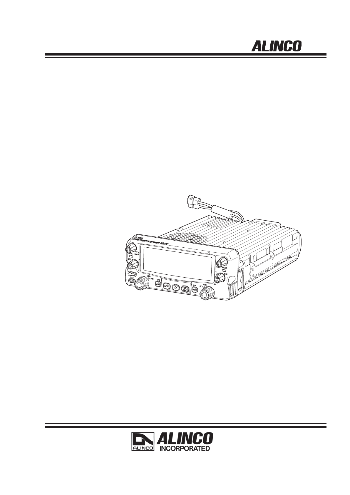
DR-735T
Instruction Manual
Thank you for purchasing your new Alinco transceiver.
This Instruction manual contains important safety and operating instructions. Please read
this manual carefully before using the product and keep it for future reference.
Page 2

NOTICE / Compliance Information Statement
This equipment has been tested and found to comply with the limits for a Class B digital device, pursuant to part 15
of the FCC Rules.
These limits are designed to provide reasonable protection against harmful interference in a residential installation.
This equipment generates, uses, and can radiate radio frequency energy and, if not installed and used in
accordance with the instruction manual, may cause harmful interference to radio communications. However, there is
no guarantee that interference will not occur in a particular installation. If this equipment does cause harmful
interference o radio or television reception, which can be determined by turning the equipment off and on, the user
encouraged to try to correct the interference by one or more of the following measure:
• Reorient or relocate the receiving antenna.
• Increase the separation between the equipment and receiver.
• Connect the equipment into an outlet on a circuit different from that to which the receiver is connected.
• Consult the dealer or an experienced radio/TV technician for help.
Changes or modifications not modifications not
expressly approved by the party responsible for compliance could void the user’s authority to operate the
equipment.
VHF/UHF FM Transceiver DR-735T
This device complies with Part 15 of the FCC Rules. Operation is subject to the two conditions: (1) This device may
not cause harmful interference, and (2) this device must accept any interference received, including interference
that may cause undesired operation.
Manufacturer: ALINCO, INC
Yodoyabashi-Dai building 13
Conformity Information
In case the unit you have purchased is marked with a CE symbol, a copy of relative conformity certificate or
document can be reviewed at http://www.alinco.com/usa.html. Please see the back-cover for more details.
Copyright © 2016 All right reserved. No part of this document may be reproduced, copied, translated or transcribed
in any form or by any means without the prior written permission of Alinco. Inc., Osaka, Japan. English Edition
Printed in Japan.
th
Floor 4-9, 5-Chome, Koraibashi, Chio-ku, Osaka 541-0043, JAPAN
This device complies with Industry Canada licence-exempt RSS standard(s). Operation is
subject to the following two conditions:
(1) this device may not cause interference, and
(2) this device must accept any interference, including interference that may cause
undesired operation of the device.
Le présent appareil est conforme aux CNR d'Industrie Canada applicables aux appareils
radio exempts de licence. L'exploitation est autorisée aux deux conditions suivantes :
(1) l'appareil ne doit pas produire de brouillage, et
(2) l'utilisateur de l'appareil doit accepter tout brouillage radioélectrique subi, même si le
brouillage est susceptible d'en compromettre le fonctionnement.
Page 3
:$51,1*
To prevent any hazard during operation of Alinco’s radio product, in this manual and on the
product you may fi nd symbols shown below. Please read and understand the meanings of
these symbols before starting to use the product.
$/(57
(QYLURQPHQWDQGFRQGLWLRQRIXVH
This symbol is intended to alert the user to an immediate
Danger
Alert
Caution
Do not drive while handling the radio for your safety. It is recommended that you
check local traffic regulations regarding the use of radio equipment while driving.
Some countries prohibit the operation of transceiver while driving.
Do not use this product in close proximity to other electronics devices, especially
medical ones. It may cause interference to those devices.
danger that may cause loss of life and property if the user
disregards the warning.
This symbol is intended to alert the user to a possible hazard
that may cause loss of life and property if the user disregards
the warning.
This symbol is intended to alert the user a possible hazard that
may cause loss of property or injure the user if the warning is
disregarded.
Alert symbol. An explanation is given.
Warning symbol. An explanation is given.
Instruction symbol. An explanation is given.
Keep the radio out of the reach of children.
In case a liquid leaks from the product, do not touch it. It may damage your skin.
Rinse with plenty of cold water if the liquid contacted your skin.
Never operate this product in facilities where radio products are prohibited for use
such as aboard aircraft, in airports, in ports, within or near the operating area of
business wireless stations or their relay stations.
Use of this product may be prohibited or illegal outside of your country. Be informed
in advance when you travel.
The manufacturer declines any responsibilities against loss of life and/or property
due to a failure of this product when used to perform important tasks like life-
guarding, surveillance, and rescue.
Do not use multiple radios in very close proximity. It may cause interference and/or
damage to the product(s).
Risk of explosion if battery is replaced with an incorrect type.
Dispose of, or recycle used batteries according to your local regulations.
The manufacturer declines any responsibilities against loss of life and property due to
a failure of this product when used with or as a part of a device made by third parties.
Use of third party accessory may result in damage to this product. It will void our
warranty for repair.
1
Page 4

WARNING
+DQGOLQJWKLVSURGXFW
Be sure to reduce the audio output level to minimum before using an earphone or a
headset. Excessive audio may damage hearing.
Do not open the unit without permission or instruction from the manufacturer.
Unauthorized modification or repair may result in electric shock, fire and /or
malfunction.
Do not operate this product in a wet place such as shower room. It may result in
electric shock, fire and/or malfunction.
Do not place conductive materials, such as water or metal in close proximity to the
product. A short-circuit to the product may result in electric shock, fire and/or
malfunction.
Do not touch the heatsink (on/around the unit mostly found on mobile-base units) as it
may become very hot during/after the operation that may risk burn your skin.
$ERXWSRZHUVXSSO\
Use only appropriate, reliable and certified power supply of correct voltage and
capacity.
Do not connect cables in reverse polarity. It may result in electric shock, fire and/or
malfunction.
Do not plug multiple devices including the power-supply into a single wall outlet. It
may result in overheating and/or fire.
Do not handle a power-supply with a wet hand. It may result in electric shock.
Securely plug the power-supply to the wall outlet. Insecure installation may result in
short-circuit, electronic shock and/or fire.
Do not plug the power-supply into the wall outlet if the contacts are dirty and/or dusty.
Shortcircuiting and/or overheating may result in fire, electric shock and/or damage to
the product.
Do not modify or remove fuse-assembly from the DC-cable. It may result in fire,electric
shock and/or damage to the product.
,QFDVHRIHPHUJHQF\
In case of the following situation(s), please turn off the product, switch off the source of
power, then remove or unplug the power-cord. Please contact your local dealer of this
product for service and assistance. Do not use the product until the trouble is resolved. Do
not try to troubleshoot the problem by yourself.
• When a strange sound, smoke and or strange odor comes out of the product.
• When the product is dropped or the case is broken or cracked.
• When a liquid penetrated inside.
• When a power-cord ( including DC-cables, AC-cables and adapters) is damaged.
For your safety, turn off then remove all related AC-lines to the product and its
accessories including the antenna if a thunderstorm is likely.
Turn off the unit, remove the mobile antenna from its base and keep it in the vehicle
if a thunderstorm is likely.
Please read cautions regarding the lightning-protection on page 9 also.
2
Page 5
0DLQWHQDQFH
Do not open the unit and its accessories. Please consult with your local dealer of this
product for service and assistance.
&$87,21
(QYLURQPHQWDQGFRQGLWLRQRIXVH
Do not use the product in proximity to a TV or a radio. It may cause interference or
receive interference.
Do not install in a humid, dusty or insufficiently ventilated place. It may result in
electric shock, fire and/or malfunction.
Do not install in an unstable or vibrating position. It may result in electric shock, fire
and/or malfunction when /if the product falls to the ground.
Do not install the product in proximity to a source of heat and humidity such as a
heater or a stove. Avoid placing the unit in direct sunlight.
Do not modify, dismantle, incinerate, or immerse the batteries. That may be used in
accessories you use with this product.
Please check your local regulations for details on recycling option or disposal of the
batteries in your area.
WARNING
$ERXWWUDQVFHLYHU
Do not connect devices other than specified ones to the jacks and ports on the
product. It may result in damage to the devices.
Turn off and remove the power-source (AC cable, DC cable, battery, cigar-cable,
charger adapter etc) from the product when the product is not in use for extended
period of time or in case of maintenance.
Never pull the cord alone when you unplug AC cable from the wall outlet.
Use a clean, dry cloth to wipe off dirt and condensation from the surface of the
product. Never use thinner or benzene for cleaning.
$ERXWSRZHUVXSSO\
Use only reliable power supply of specific DC output range and be mindful of the
polarity of the cables and DC jack.
Always turn off the power supply when connecting or disconnecting the cables.
When using an external antenna, make sure that the antenna ground is not common
with the ground of the power supply.
European users: When a transceiver is powered from an external DC power source
(adapter, power supply, cigar-plug etc), make sure that this power supply has
approval to the level of IEC/EN 60950-1.
3
Page 6
%HIRUH2SHUDWLQJWKH7UDQVFHLYHU
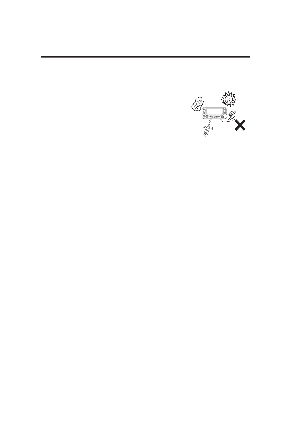
$WWHQWLRQ
• Do not remove the case or touch the interior components. Tampering can cause equipment
trouble.
• Do not use or keep the transceiver where it is exposed to direct sunlight, dusty places, or
near sources of heat.
• When transmitting for long periods of time at high power,
the transceiver might overheat. This product is NOT a
100% -duty transmitter.
• Turn the power off immediately if the transceiver emits
smoke or strange odors. Ensure the transceiver is safe,
then bring it to the nearest Alinco service center.
• An operator’s license is required for this device.
Notice to California resident users
The product that comes with this manual is free from dangerous material such as lead and
cadmium as per RoHS order of EU.
The transceiver has no protection against lightning.
The user is responsible for providing adequate protection if he/she uses the device at home
and installs the antenna outdoor. Be aware that any outdoor antenna creates a direct path for
lighting current (more than 10kA) to the transceiver. This path exists whether the device is
turned ON or OFF.
Any vehicle does not present a safe environment during lightning. This environment becomes
much more dangerous if an outdoor antenna is installed on the car. Move the antenna and its
cable into the car at the first sight of forthcoming thunderstorm and lightning.
,QWURGXFWLRQ
Thank you very much for purchasing this excellent Alinco transceiver. Our products are
ranked among the finest in the world. This radio has been manufactured with state of the art
technology and it has been tested carefully at our factory. It is designed to operate to your
satisfaction for many years under normal use.
PLEASE READ THIS MANUAL COMPLETELY TO LEARN ALL THE FUNCTIONS THE
PRODUCT OFFERS. WE MADE EVERY ATTEMPT TO WRITE THIS MANUAL TO BE
AS COMPREHENSIVE AND EASY TO UNDERSTAND AS POSSIBLE. IT IS IMPORTANT TO
NOTE THAT SOME OF THE OPERATIONS MAY BE EXPLAINED IN RELATION TO
INFORMATION IN PREVIOUS CHAPTERS. BY READING JUST ONE PART OF THE
MANUAL, YOU RISK NOT UNDERSTANDING THE COMPLETE EXPLANATION OF THE
FUNCTION.
4
Page 7

%HIRUHRSHUDWLQJWKHWUDQVFHLYHU
,QWURGXFWLRQ
Thank you very much for purchasing this excellent Alinco transceiver. Our products are
ranked among the finest in the world. This radio has been manufactured with state of the art
technology and it has been tested carefully at our factory. It is designed to operate to your
satisfaction for many years under normal use.
PLEASE READ THIS MANUAL COMPLETELY TO LEARN ALL THE FUNCTIONS THE
PRODUCT OFFERS. WE MADE EVERY ATTEMPT TO WRITE THIS MANUAL TO BE AS
COMPREHENSIVE AND EASY TO UNDERSTAND AS POSSIBLE. IT IS IMPORTANT TO
NOTE THAT SOME OF THE OPERATIONS MAY BE EXPLAINED IN RELATION TO
INFORMATION IN PREVIOUS CHAPTERS. BY READING JUST ONE PART OF THE
MANUAL, YOU RISK NOT UNDERSTANDING THE COMPLETE EXPLANATION OF THE
FUNCTION.
5
Page 8
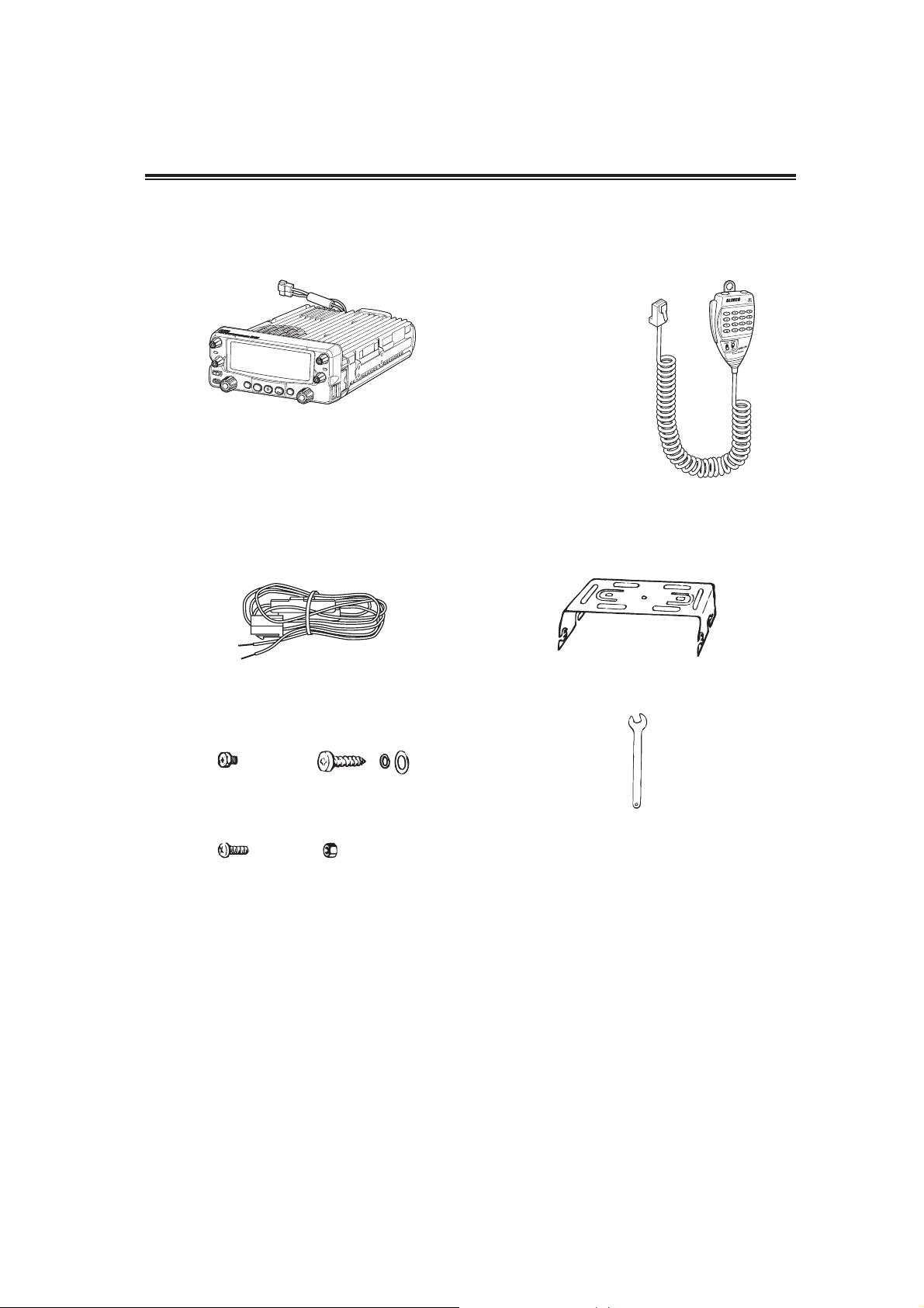
6WDQGDUG$FFHVVRULHV
Carefully unpack to make sure the following items are found in the package in addition to this manual.
Tran sc eiv e r
(15A fuse)
VOL
BAND
MAIN
SQL
MHz
SET
SCAN
MW
V/M
MW
VOL
MAIN
BAND
SQL
MHz
MW
SCAN
H/L
V/M
DC power cable including 15A fuse and
EMS79 (with DTMF keypad)
Mobile Mounting bracket
holder
UA0038Y FM0078Z
Hardware kit for bracket Small (spanner) wrench
Bracket screws
AE0012
(M4 x 8mm) x 4
Screws
(M5 x 20mm) x 4
Tapping screws
(M5 x 20mm) x 4
Hexagonal nut
(M5) x 5
Instruction manual
The standard accessories may vary slightly depending on the version you have purchased.
Please contact your local authorized Alinco dealer should you have any questions.
Standard accessories may change without notice.
Warranty Policy
Please refer to any enclosed warranty information or contact your authorized Alinco dealer/distributor for the
warranty policy before purchase.
6
Page 9
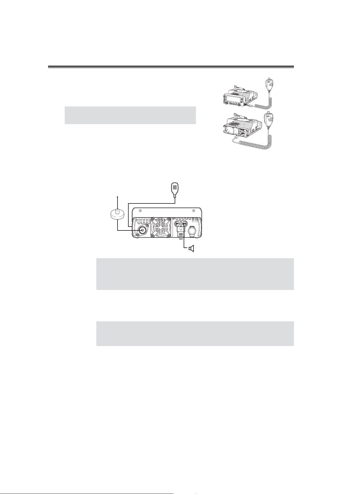
,QLWLDO,QVWDOODWLRQ
0LFURSKRQHFRQQHFWLRQ
Connect the microphone plug into microphone terminal on the
right side of control panel or into other microphone terminal in
front of MAIN unit. Insert the plug until hearing a click.
IMPORTANT
When connecting, take care to the modular
plug direction.
$QWHQQD&RQQHFWLRQ
Connect antenna port to 50: antenna that covers 2m/70cm bands, using good quality 50 : coaxial cable.
Microphone
Antenna
V
O
L
rear panel
Coupling the antenna to the transceiver via feed-lines having impedance
IMPORTANT
other than 50: reduces the efficiency of the antenna system and can cause
interference to nearby televisions, radio receivers and other electronic
equipment.
)RUDEDVHVWDWLRQVHWXS
• Before connecting, be sure to turn off the transceiver and DC power
IMPORTANT
The transceiver requires 13.8V DC negative grounded power supply.
Use a regulated power supply capable of providing continuous current of 12A or more.
Power supplies that do not meet does specifications may cause malfunction and/or damage
to the radio and will void the warranty. Alinco offers excellent communication-grade power
supplies as optional accessories. Please contact your local authorized Alinco dealer.
supply.
• Be certain to use DC cable provided with unit.
External speaker
(if used)
7
Page 10
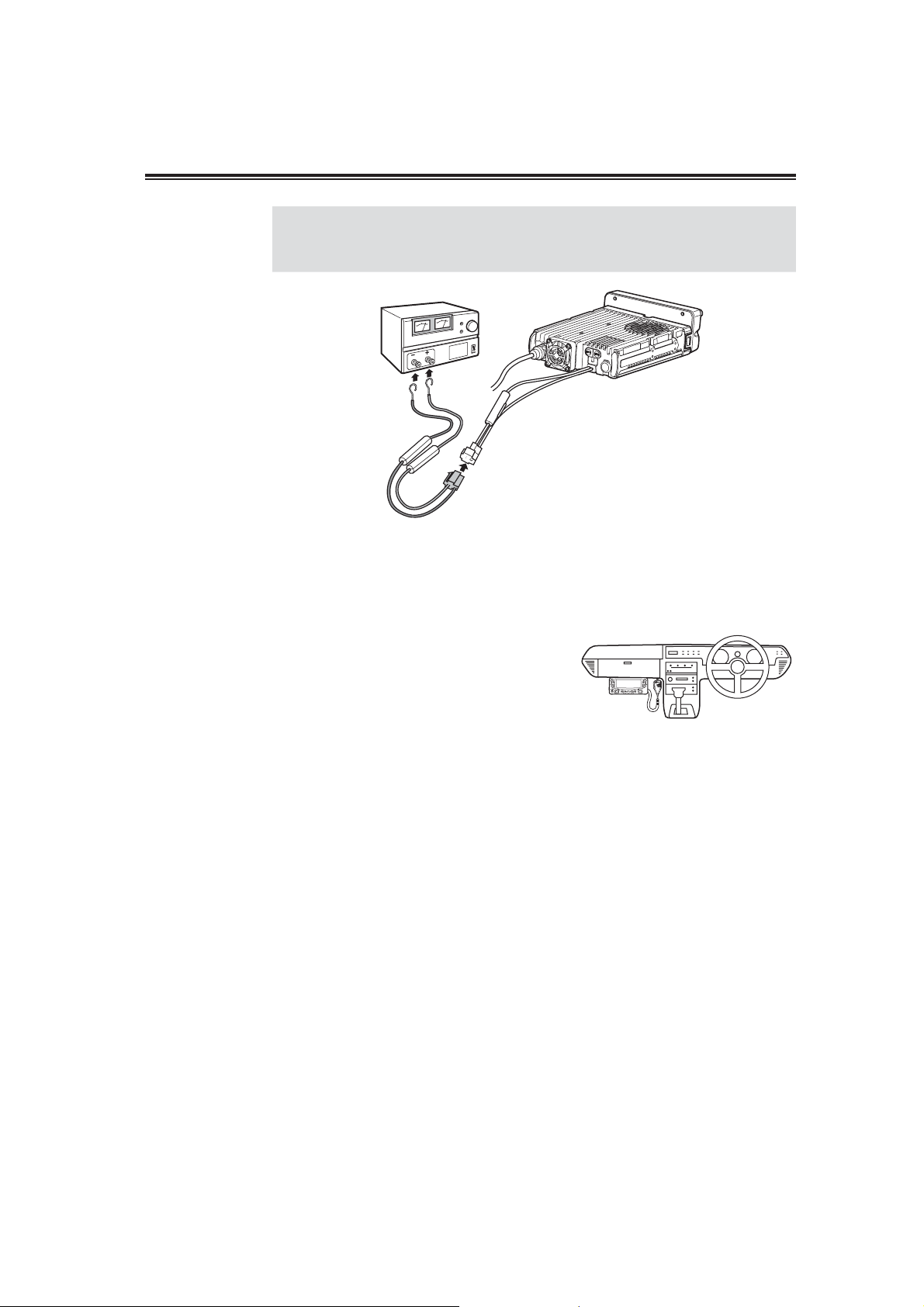
DC voltage range for operating this transceiver is DC 11.7V to 15.8V.
IMPORTANT
Transceiver will not operate out of this range. Inspect cable and connection
regularly to be sure there is not any damage or burning.
DC
power
supply
Black
lead
Red
lead
)RUPRELOHVWDWLRQVHWXS
Initial Installation
DC power cable
/RFDWLRQ
The transceiver may be installed in any position in
your vehicle, where the controls and microphones
are easily accessible and it does not interference
with the safe operation of the vehicle or the
performance of the set. If your vehicle is equipped
with air bag, be certain your radio will not
interference with their deployment. If you are uncertain about where to mount the unit, contact
your vehicle’s manufacture.
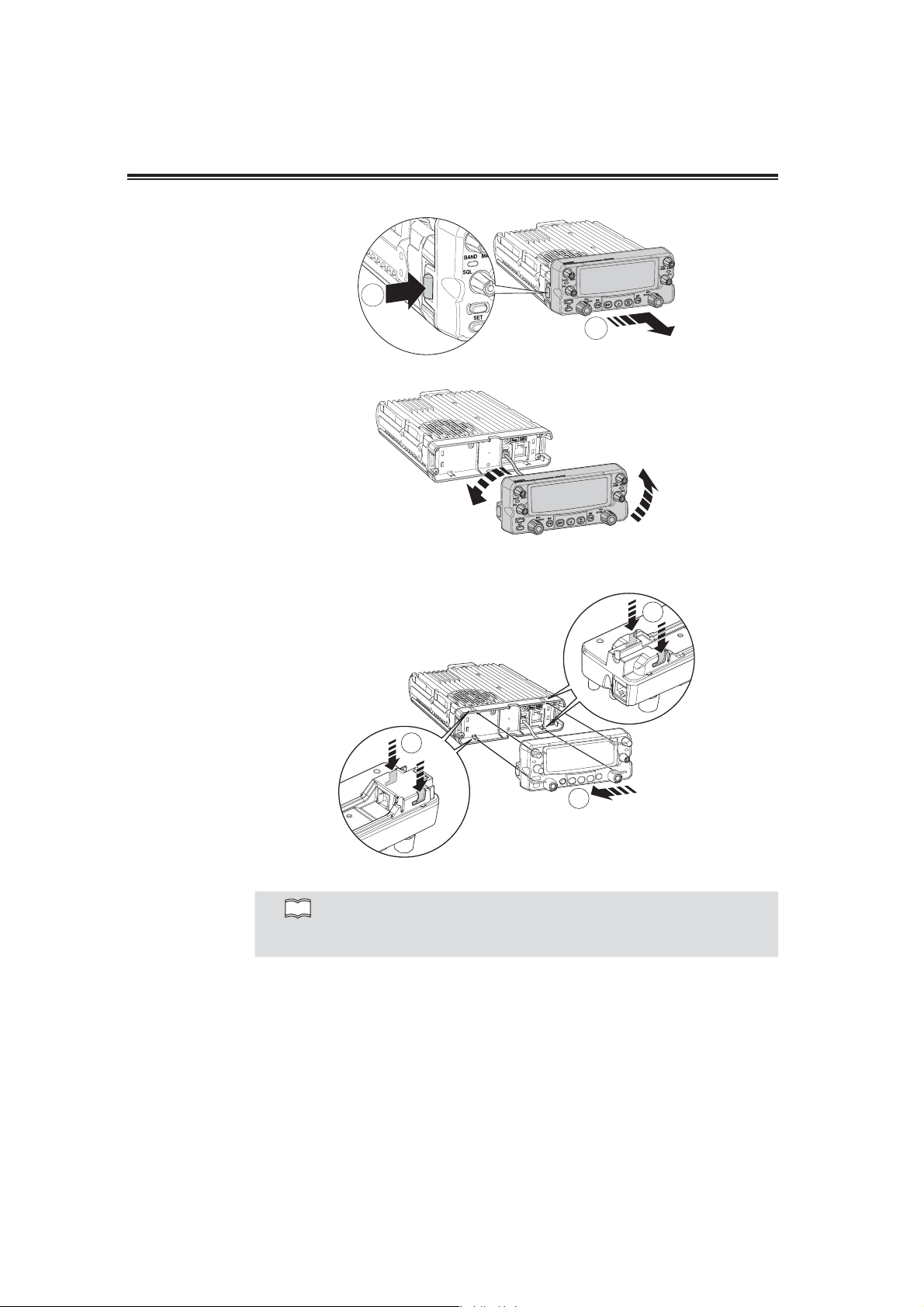
)URQW3DQHO
The main unit can be set with either side facing up. This can facilitate your ability to hear the
speaker’s audio clearly. Position the front panel as you prefer.
1. Slide the front panel while pulling the tab
toward yourself.
2. Turn the front panel, being careful to keep
the cable free from kinks.
3. Match the catch in the main unit with the
slot in the front panel and fit the front
panel into the main unit.
4. Slide the front panel unit until it locks
securely in place.
8
Page 11
Initial Installation
1
2
NOTE
④Match the catch in the main unit with
the slot in the front panel and fit the
front panel into the main unit.
4
4
5
⑤Slide the front panel unit until it
locks securely in place.
By using the optional separation kit EDS-30, you can use the control and
the main unit in separate positions. The length of separation cable is 5m.
See page 75 for details.
9
Page 12
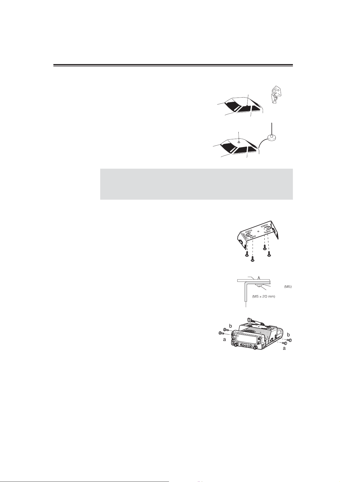
,QVWDOOLQJD0RELOH$QWHQQD
Use a 50: coaxial cable to connect the antenna.
Mobile antennas require an appropriate mounting
base for proper installation and operation. For more
information, see the documentation for your
antenna.
After installing your antenna, ensure that you have the best possible SWR
IMPORTANT
reading. High RF environments can cause severe damage to your unit.
Ensure that you are not in a high RF environment when operating the
transceiver.
8VLQJWKHPRXQWLQJEUDFNHW
Initial Installation
Screw-fixed base
Magnet base
1. Drill 4 holes where the mounting bracket
is to be installed.
. Approx. 5.5-6mm (1/4”) when using nuts; approx.
2-3 mm (1/8”) when using self-tapping screws.
2. Insert the supplied screws, nuts and
washers through the mounting bracket
and tighten.
3. Adjust the angle fort your suitable
position.
<For making 4+/-0.2mm hole in
globe box bottom>
Car body
Washer
Tapping screw
Mounting bracket
VOL
10
Page 13
&RQWUROV&RQQHFWRUVDQG'LVSOD\
&RQWURO.H\V2SHUDWLRQ0HWKRGV
There are 3 types of key operations; simply press, press after pressing [FUNC] key while FUNC appears on
the display, or press and hold.
• [Press] refers to one time quick press and remove finger.
• [FUNC + this Key] refers to one time press [FUNC] key and then pressing this key while FUNC appears
on the display.
• [Press and hold] refers to press key and hold it. Hold timing is adjustable in set mode; however factory
default is 2 sec.
To confirm a parameter, [press any keys other than these keys] or [press microphone`s PTT switch] are
mentioned in this instruction manual. Quickest way to confirm parameters is pressing microphone’s PTT
switch.
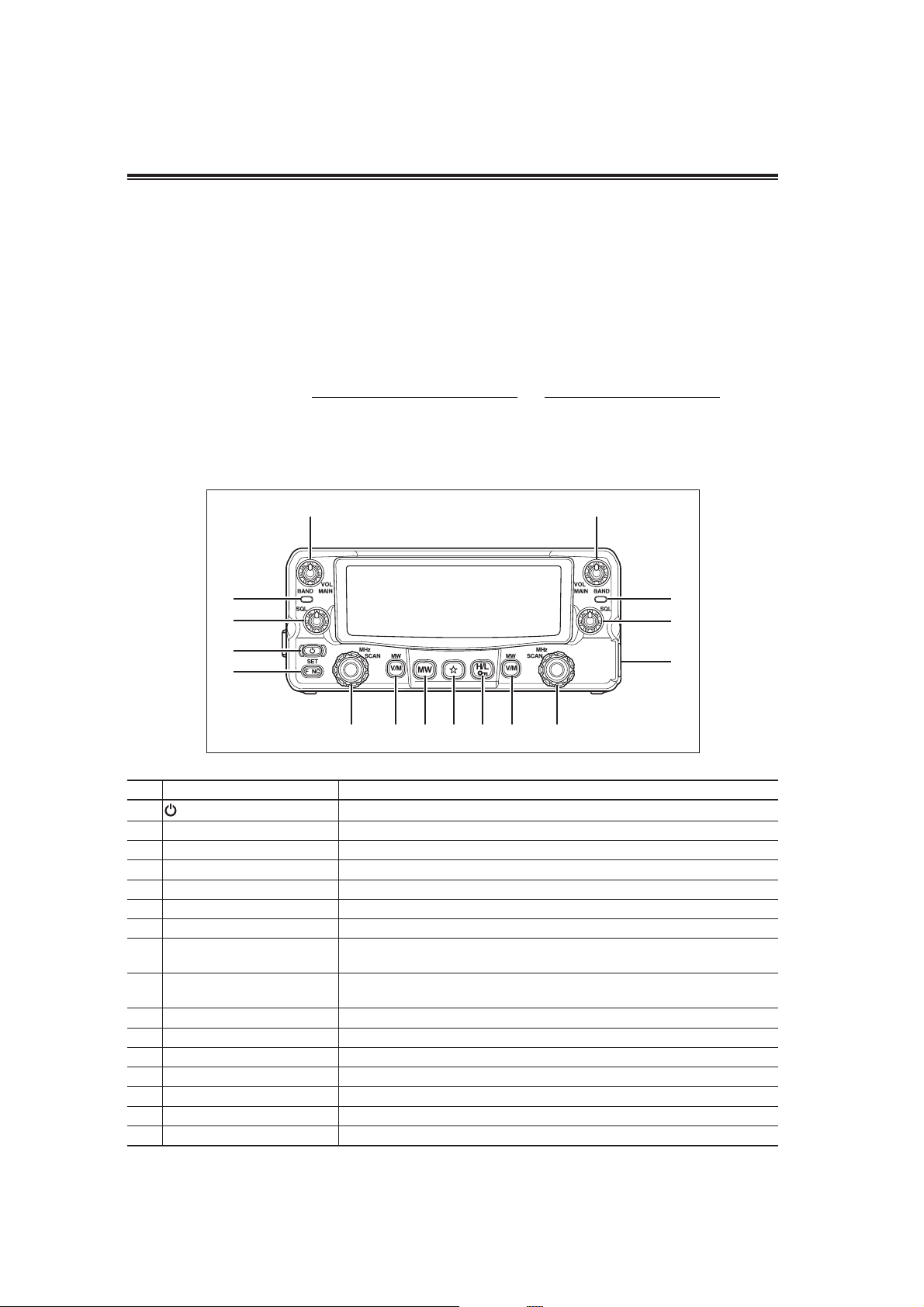
)URQW3DQHO
②
④
⑥
①
⑩
U
③
⑨⑫⑮⑭⑬⑪⑧
Primary Functions
No. Key Function
A
Power Key
Left band [VOL] knob Rotate to adjust audio sound level on the left band. (P.19)
B
Right band [VOL] knob Rotate to adjust audio sound level on the right band. (P.19)
C
Left band TX /RX indicator Indicates transmission (Red) or reception (Green) on the left band.
D
Right band TX/RX indicator Indicates transmission (Red) or reception (Green) on the right band.
E
Left band [SQL] knob Rotate to adjust squelch level on the left band. (P.20)
F
Right band [SQL] knob Rotate to adjust squelch level on the right band. (P.20)
G
Left band dial
H
Right band dial
I
[FUNC] key Sets functions.
J
Left band [V/M] key Switches between VFO mode and memory mode on the left band.
K
Right band [V/ M] key Switches between VFO mode and memory mode on the right band.
L
[MW] key Press to select dual Memory mode.
M
N
key
[H/ L] key Press to select Hi/Mid and Low output power. (P.33)
O
Microphone connector For connecting microphone.
P
Turns the power on/off. (P.19)
Rotate to select frequency, memory channel and various settings on the left
band.
Rotate to select frequency, memory channel and various settings on the right
band.
Programmable function key.(P.63)
⑤
⑦
⑯
11
Page 14
Controls, Connectors, and Display
Functions that requires press and holding to be activated
No. Key Function
Left band [VOL] knob Switches between VHF/Air-Band and UHF on the left band (P.19)
B
Right band [VOL] Knob Switches between UHF/ VHF and Air-Band on the right band (P.19)
C
Left band dial Switches between VFO and memory scan on the left band. (P.58)
H
Right band dial Switches between VFO and memory scan on the right band. (P.58)
I
[FUNC] key Sets mode. (P.34)
J
Left-Band [V/M] key Switches to Call channel on the Left-Band. (P.30)
K
Right-Band [V/M] key Switches to Call channel on the Right-Band. (P.30)
L
[MW] key Simple Memory writing. (P.24)
M
[H/ L] key Key lock. (P.62)
O
* Hold timing is adjustable in set mode
Functions which can be activated while [FUNC] appears, after pressing [FUNC] key
No. Key Function
Left band [VOL] knob Switches to the single band mode on the left band. (P.57)
B
Right band [VOL] knob Switches to the single band mode on the right band. (P.57)
C
Left band dial Program scan on the left band. (P.60)
H
Right band dial Program scan on the right band. (P.60)
I
Left band [V/ M] key Write frequency to selected memory on the left band. (P.23)
K
Right-Band [V/ M] key Write frequency to selected memory on the right band. (P.23)
L
[MW] key Sets monitor function. (Reverse function when shift activated). (P.31)
M
N
key
[H/ L] key Accesses the digital voice communication mode (required optional unit) (P.66)
O
Selects Tone-squelch (CTCSS) or DCS. (P.64)
Functions which can be activated while pressing the [FUNC] key
No. Key Function
A
Power key
Left band [VOL] knob Selects shift or offset frequency on the left band. (P.22)
B
Right band [VOL] knob Selects shift or offset frequency on the right band. (P.22)
C
Left band dial Sets priority scan on the left band. (P.60)
H
Right band dial Sets priority scan on the right band. (P.60)
I
Left band [V/ M] key Erase the memory while memory mode is selected on the left band. (P.25)
K
Right band [V/M] key Erase the memory while memory mode is selected on the right band. (P.25)
L
[MW] key Sets auto-dialer memory. (P.74)
M
N
key
[H/ L] key Sets the channel name while Memory mode selected. (P.28)
O
Normal Reset when turns the power on. (P.73)
Sets RGB backlight color. (P.63)
12
Page 15
Controls, Connectors, and Display
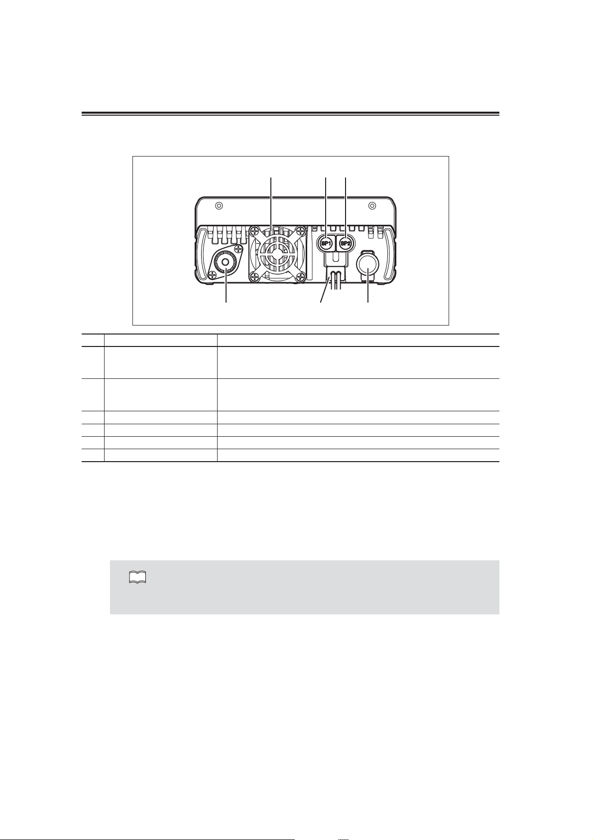
5HDU3DQHO
④①②
⑥③⑤
No. Key Function
Connects an external 8: speaker. Output audio from right band. When
External Speaker Jack 1 [SP1]
A
External Speaker Jack 2 [SP2]
B
DC Power cable Connects to the 13.8V DC power supply.
C
Air-cooling fan Cools the unit during transmission or when radio is holding high temperature.
D
Antenna connector Connects to antenna with 50: impedance matched with operation frequency.
E
DIN connector (6 PIN) Connects to external TNC unit for Packet communications.
F
another speaker is not connected to [SP2] , left band audio hear through
internal speaker. Also [SP1] used for connecting clone or PC cables.
Connects an external 8: speaker. Output audio from left band. When another
speaker is not connected to [SP1], right band audio hear through internal
speaker.
$QWHQQD&RQQHFWLRQ
Before operating, install an efficient, well-tuned antenna. The success of your installation will depend on the
type of antenna and its correct installation. Use a 50: impedance antenna and low-loss coaxial feed-line
that has a characteristic impedance of 50:, to match the transceiver input impedance.
Coupling the antenna to the transceiver via feed-lines having impedance other than 50 : reduces the
efficiency of the antenna system and can cause interference to nearby televisions, radio receivers and other
electronic equipment.
Transmitting without first connecting an antenna or other matched load may damage the
NOTE
transceiver. Always connect the antenna to the transceiver before transmitting.
All fixed stations should be equipped with a lightning protection to reduce the risk of fire,
electric shock, and transceiver damage.
([WHUQDO6SHDNHU&RQQHFWLRQ
• If you plan to use an external speaker, choose a speaker with an impedance of 8 :. Each external speaker
jacks accept a 3.5mm (1/8") mono (2-conductor) plug.
• External speaker adopt double port BTL, please care about the connection. Do not use the speaker that
requires grounding.
• Carefully insert plug into jack. Do not twist the plug and do not apply stress on speaker jack.
• When jacks are not in use, keep the [SP] cap (speaker jack cover) closed to keep contacts clean and
avoid entering dust and other objects into the radio.
• Insert plug into jack completely until end to prevent damaging the jack or plug.
13
Page 16
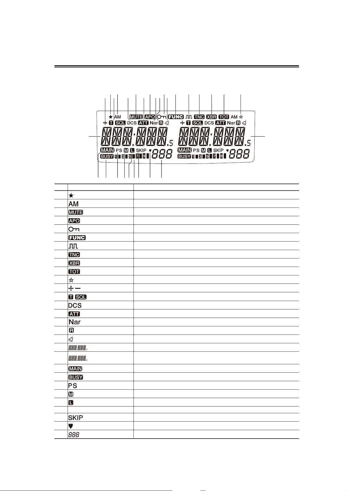
'LVSOD\
Controls, Connectors, and Display
䷶
䷵
一
丁
䷷ ䷸ ䷹ ䷺ ䷻ ䷼ ䷽ ䷾ ䷿
丂
七丆
丄丅
万
具典 兹兺养兼兽 兾 兿
No. Key Function
A
B
C
D
E
F
G
H
I
J
K
L
M
N
O
P
H
I
J
K
L
M
N
O
P
Q
S meter Indicates received or transmitted signal level. (P.31, 32)
R
S
T
Appears when advanced set mode is available. (P.48)
Appears during AM reception. (P.36)
Appears during transmission when other band is set for mute. (P.52)
Appears when APO function is activated. (P.49)
Appears when setting the key lock. (P.62)
Appears when [FUNC] key is pressed. (P.17)
Appears when in the digital voice communication mode. (P.66)
Appears when in packet mode. (P.55)
Appears when cross-band repeater mode is available.
Appears during time out timer setting. (P.49)
Appears during short cut setting. (P.63)
Appears when setting the shift. (P.22)
Appears when setting the tone squelch. (P.64)
Appears when setting the DCS. (P.65)
Appears when attenuator function is activated. (P.44)
Appears when in narrow band reception mode. (P.36)
Appears when reverse mode is activated. (P.32)
Appears when Bell function is activated. (P.39)
Indicates the VHF/ UHF frequency or memory name on the left band side. (P.20, 31)
Indicates the VHF/ UHF frequency or memory name on the right band side.
(P.20, 31)
Appears on the band with transmitting ability. (P.19)
Appears when a signal is being received. (P.31)
[S] Flashes during scan and [PS] flashes during program scan. (P.58)
Appears when transmission power is set to MID. (P.33)
Appears when transmission power is set to LOW. (P.33)
Appears during scan for skip channels. (P.59)
Appears when favorite channel is selected. (P.59)
Indicates memory numbers in the memory mode. (P.23)
丈
14
Page 17

Controls, Connectors, and Display
0LFURSKRQH(06
①②
③
④
No. Key Function
UP Increase the frequency, memory channel number, or setting value.
A
DOWN Decrease the frequency, memory channel number, or setting value.
B
MAIN PTT
C
SUB PTT
D
LOCK SWITCH Locks out the UP and DOWN keys.
E
MIC Speak here during transmission.
F
Press the PTT (Push-To-Talk) key to transmit. Also press this key to confirm
your selection.
Press the PTT (Push-To-Talk) key to transmit on sub band. Also used for other
functions depends on setting in set mode. (P.45)
⑥
⑤
Microphone Connector pin Assignment (Viewed from front of unit)
1.DC5V
2.DOWN
3.REMOTE
4.PTT
5.MIC GND
6.MIC
18
7.GND
8.UP
IMPORTANT
• Connect the microphone modular plug provided with the unit into microphone jack.
• Insert the plug until hearing a click. When connecting, take care to the modular plug
direction.
• When removing microphone from unit, press the lock on connector then pull the plug
out. Do not pull the microphone’s cable to remove the microphone from radio.
• When using optional EDS-8 (8 pin to modular convertor), fix EDS-8 cable on the
bracket to avoid stress on modular socket.
• Be careful to not mis-connecting separation cable to microphone’s modular socket.
15
Page 18

%DVLF2SHUDWLRQV
7XUQLQJWKHXQLWRQDQGRII
By press and holding the PWR key the power is turned on. By press and
holding the PWR key again, the power is turned off. To avoid accidentally turn
on/off, PWR key operation is designed for press and hold.
6ZLWFKLQJWKH0$,1EDQG
In this instruction manual the MAIN band refers to the band which
selected for transmitting with MAIN icon on the display. To select MAIN
band press left or right volume knob. Press main PTT switch on
microphone to transmit on the MAIN band.
For transmit on sub band without switching MAIN, set SUB-PTT switch on
NOTE
6ZLWFKLQJRSHUDWLRQEDQG
Press and hold VOL knob for changing band (frequency). By
press and holding VOL knob, VHF->Air-Band VHF->UHF
appears on the display.
Also selecting same band for left and right is possible. (V-V or
U-U reception)
[AM] appears on the display when Air-band selected as factory
default setting.
EMS-78 microphone for TX in set mode. (P.45)
During memory scan (P.59), receiving band becomes MAIN band
automatically.
PWR key
VOL knob
IMPORTANT
When V-V/U-U/V-Air-band is selected, during transmission on main band reception on sub
band becomes mute.
$XGLR9ROXPHOHYHOVHWWLQJ
The volume of the left band is adjusted by the left VOL knob
and the volume of the right band by the right VOL knob.
Rotate the VOL knob clockwise to increase the audio level,
counterclockwise to decrease.
16
Low
Volume
VOL knob for
left band
High
Volume
Low
Volume
VOL knob for
right band
High
Volume
Page 19

Basic Operations
6TXHOFKOHYHOVHWWLQJ
low
Adjust threshold level of the squelch. A squelch eliminates the
background noise when a signal is not received.
Turn the SQL knob clockwise until white-noise (the background
noise when a signal is not received) and [BUSY] icon on the
display disappears.
The SQL should be turned fully counterclockwise when receiving weak or unstable signals. The [BUSY] icon
appears on the display while the squelch is opened (unmuted).
When you set it to a higher level, weak signals would be interrupted while monitoring or would not be
monitored at all.
Generally, you should set the squelch to the lowest level where noise would be eliminated. Depending on the
monitored frequencies and the conditions of the circumstances around you, the squelch level may need to
be adjusted
high low high
SQL knob for
left band
VOL knob for
Right band
NOTE
Attenuator function is available for SQL knob. (P.44)
17
Page 20

7RUHFHLYHVLJQDOV
1. Be sure to have the unit connected to the
appropriate antenna, powered on, set the
audio volume and squelch level properly
on both the MAIN and SUB bands.
2. Select the desired band and browse
frequencies or select desired frequency
to listen to ongoing communications. The
S-meter shows relative signal strength
when the transceiver detects an incoming
signal, and the RX indicator lamp (green)
turns on.
3. If the S-meter indicates an incoming
signal but nothing is heard from the
speaker, check the audio level, squelch
level, and CTCSS/DCS decoding status,
which are explained elsewhere in this
manual.
Basic Operations
S-meter
18
0RQLWRU)XQFWLRQ
This function is used to listen to weak signals. The
monitor function operates irrespective of Tone squelch /
DCS functions setting.
Select desired band as MAIN. Press
FUNC key then press MW key while
[FUNC] appears on the display.
Regardless of the level setting of the squelch, it will be
opened; BUSY icon flash and RX lamp will turn on.
4. Press any key on the front panel to exit.
IMPORTANT
The Monitor function only operates on the MAIN band.
Page 21

Basic Operations
5HYHUVH)XQFWLRQ
1. Set SHIFT first. Press FUNC key then
2. Pressing any key on the front panel will
This function is for monitoring the transmission
frequency instead of reception frequency in repeater
operation. This technique is commonly used to check if
it is possible to communicate without using repeater by
monitoring the accessing station’s signal strength.
press MW key while [FUNC] appears on
display.
[ ] icon illuminates on the display to indicate that the
reverse function is activated and the squelch opens.
cancel the operation.
The Reverse function only operates on the MAIN band.
IMPORTANT
Without SHIFT setting Monitor function will operate instead of Reverse
function.
Auto repeater setting
7R7UDQVPLW
1. Set the transmission band to the MAIN
side.
2. Be sure that you are authorized to
operate on the selected frequency. Check
the system and monitor the frequency to
make sure that you are not going to
disturb any ongoing communications.
3. Press the PTT key on the microphone.
The TX lamp (red) illuminates to show the unit is
transmitting.
4. Speak into the microphone in a normal
tone while keeping the PTT key pressed.
Hold the microphone approximately 5cm away from
your mouth. Speaking too close or too loud may result
in poor transmitted audio. Adjust microphone gain in set
mode (Menu 03)
NOTE
Rotate squelch knob to monitor repeater’s down link.
TX lamp
19
Page 22

5. Releasing the PTT key will complete the
transmission and the unit will return to
the receive mode.
Pressing the DOWN key together with the PT T key will transmit the CALL
NOTE
tone signal. DR-735T will transmit the Tone Burst signal.
Basic Operations
IMPORTANT
If you press the PTT key while out of the transmission frequency range, the
[OFF] icon will appear on the display and no transmission will occur.
6HOHFWLQJ7UDQVPLVVLRQ3RZHU
1. Press H/L key. The transmission power
switches from high to middle to low and
then low to high.
At middle power, the [ ], and at low power, the [ ]
illuminates. Nothing appears on the display at high
power. The default is high power.
The RF meter shows when transmitting at low
power, and at middle power, and
at high power.
Transmission
Power
at low power
at middle power
at high power
20
IMPORTANT
NOTE
• The output power level cannot be changed during transmission.
• The output power level cannot be changed during scanning.
M power output level is adjustable in set mode (P.54); however RF meter will
not change.
Page 23

6HWPRGH
Please read the following pages thoroughly prior to changing any parameters. The
IMPORTANT
$OLVWRIVHWWLQJPRGHSDUDPHWHUV
Copy or cut the following list of the setting mode parameters for your convenience.
Menu Default Display Function Default Value
01 AUTO AUTO Channel Steps setting AUTO AUTO
02 AUTO AUTO Operating mode selection AUTO AUTO
03 MCGAIN 0dB Microphone gain Adjusting 0dB
04 BUSY BUSY Scan type selection BUSY BUSY
05 SKIP SKIP Memory cancel mode selection SKIP SKIP
06 BEEP 2 Beep level selection 2
07 VFO - BP ON Incoming call display… ON
08 BEL - OF BEL - OF Incoming call display OFF OFF
09 CLMODE ALL Color mode function selection ALL
10 SB CL0 SB CL0
11 RX CL0 RX CL0
12 T X CL0 TX CL0
13 DIMMER 10 Dimmer 10
14 LAMP OFF Back light timer OFF
15 CN TRST 3 Contrast setting 3
16 ATT - OF ATT - OF Attenuator selecting OFF OFF
17 MPRTCT OFF Memory protection OFF
18 SUBPTT OFF Sub PTT allocation function OFF
19 KEY 2 Key push and hold time selecting 2
20 AUTRPT ON Auto repeater ON
21 RESTOR OFF Restore function OFF
parameters in set mode cannot be set without entering the set mode.
By entering the set mode, some of the radio’s operating parameters can be changed to suit
your application. The following is the selectable parameters menu.
Illumination color switching during the
waiting time
Illumination color switching when receiving
signal
Illumination color switching when
transmitting
CL0 CL0
CL0 CL0
CL0 CL0
21
Page 24

7RXVHWKHVHWPRGHSDUDPHWHUVVHWWLQJPRGH
1. Press and hold FUNC key to enter the Set
mode. Menu number and parameter will
appear on the display.
Set mode
2. Select a menu by pressing left dial knob
to decrease menu number or right dial
knob to increase menu number, or UP/
DOWN keys on the microphone. Push and
hold dial for parameters slide show.
3. Rotate the dial to change settings.
Rotate left dial to change parameters on left side and
right dial for right side.
4. Pressing dial or UP/ DOWN keys on the
microphone will complete the setting and
enter the next menu.
5. Pressing any key other than the dial knob
or the UP/DOWN keys will complete the
setting and the unit will exit the parameter
setting mode.
Some parameters are assigned to only left or right band and some
IMPORTANT
parameters are not changeable. For details please refer to explanation for
each menu.
Default display
22
Page 25

Set mode
6HWPRGHPHQX
0HQX&KDQQHO6WHSVVHWWLQJ
This is to select the channel step to be used in the VFO mode. Refer to the P.21for the
sequence of the actual steps and how they are displayed.
0HQX2SHUDWLQJPRGHVHOHFWLRQ
Operating modes are determined by the modulation of the radio signals. The transceiver has
total 5 operating modes (AUTO, FM, NFM, AM, NAM modes). The mode selection is stored
independently for each band and memory channel. Typically, AM mode is used for the air
band (118–136.995 MHz), and receive is only available.
1. Press and hold FUNC key to enter the
parameter set mode. Press dial to select
menu 02. Factory default setting is
[Auto].
2. Rotate the dial to select FM, NFM, AM or
NAM. When NFM or NAM selected Nar will
appear on the display.
NAMAMNFMFMAUTO
3. Pressing any key other than the dial knob
or the UP/DOWN keys will complete the
setting and the unit will exit the parameter
setting mode.
0HQX0LFURSKRQHJDLQ$GMXVWLQJ
1. Press and hold FUNC key to enter the
parameter set mode. Press dial to select
menu 03.
Factory default setting is [0dB]. This
setting is individual regardless of the
band or VFO.
2. Rotate the right dial to select a value
between -23dB to +23dB.
Selecting (-) will decrease and (+) will
increase microphone’s gain. Also
microphone gain can be adjusted during
transmission.
23
Page 26

3. Pressing any key other than the dial knob
or the UP/DOWN keys will complete the
setting and the unit will exit the parameter
setting mode.
Set mode
IMPORTANT
Pressing PTT switch will not exit the set mode setting.
0HQX6FDQW\SHVHOHFWLRQ
This is to select the scan resume condition. The BUSY setting resumes scanning when
received signal is gone and TIME setting allows the radio to resume scanning after 5, 10,
20,30 or 60 seconds. This parameter can be selected for both left and right sides in VFO
mode and cannot be selected for each band.
1. Press and hold FUNC key to enter the
parameter set mode. Press dial to select
menu 04. Factory default setting is
[BUSY].
2. By rotating the dial, the display changes
as shown and the scan type will be
changed.
3. Select a desired item.
4. Pressing any key other than the dial knob
or the UP/DOWN keys will complete the
setting and the unit will exit the parameter
setting mode.
BUSY TIME05 TIME10 TIME20 TIME30 TIME60
(seconds)
0HQX0HPRU\VFDQPRGHVHOHFWLRQ
Use this function to select memory scan conditions. (P.59)
This parameter can be selected for both left and right sides in VFO mode and cannot be
selected for each band.
1. Press and hold FUNC key to enter the
parameter set mode. Press dial to select
menu 05. Factory default setting is
[SKIP].
24
ALLSKIP FAV
Page 27

Set mode
2. Rotate the dial to select a desired item.
SKIP : Skips unwanted channels that inconveniently
stop scanning.
ALL : Repeatedly scans all frequenciesover the entire
band regardless of the SKIP or FAV channels.
FAV : Scans only favorite channels.
3. Pressing any key other than the dial knob
or the UP/DOWN keys will complete the
setting and the unit will exit the parameter
setting mode.
0HQX%HHSOHYHOVHOHFWLRQ
This is to change the volume of a beep sound during operation.
1. Press and hold FUNC key to enter the
parameter set mode. Press dial to select
menu 06. Factory default setting is [2] .
2. By rotating the right dial, the display
changes as shown and the volume of the
beep sound will be changed. This setting
is individual regardless of the band or
VFO.
3. Pressing any key other than the dial knob
or the UP/DOWN keys will complete the
setting and the unit will exit the parameter
setting mode.
Volume 0 Volume low Volume high
25
Page 28

0HQX9)2%HHSVHOHFWLRQ
1. Press and hold FUNC key to enter the
parameter set mode. Press dial to select
menu 07. Factory default setting is [OFF].
2. Rotate the right dial to select a desired
item. This setting is individual regardless
of the band or VFO.
3. Pressing any key other than the dial knob
or the UP/DOWN keys will complete the
setting and the unit will exit the parameter
setting mode.
0HQX,QFRPLQJFDOOVHOHFWLRQ%HOO
Incoming call function informs you that you are being called by sounding a bell, and flashing
the bell icon on the display.
Set mode
1. Press and hold FUNC key to enter the
parameter set mode. Press dial to select
menu 08. Factory default setting is [OFF].
This parameter can be selected for both
left and right sides in VFO mode and
cannot be selected for each band.
2. By rotating the dial, the display changes
as shown and the bell function setting is
changed.
3. Pressing any key other than the dial knob
or the UP/DOWN keys will complete the
setting and the unit will exit the parameter
setting mode.
When bell is on:
• Bell icon appears on the display.
• When squelch becomes open, bell icon will flash and beep sound will be hear.
• No beep sound during communications.
26
Page 29

Set mode
0HQX&RORUPRGHVHOHFWLRQ
This is the mode to select color mode for various conditions.
1. Press and hold FUNC key to enter the
parameter set mode. Press dial to select
menu 09.
2. By rotating the right dial, the display
changes as shown and the color mode
MEMORYALL RAINBW
function selection is changed.
3. Pressing any key other than the dial knob
or the UP/DOWN keys will complete the
setting and the unit will exit the parameter
setting mode.
ALL : The color on the left and right sides of the display can be adjusted regardless of
the main band, sub band, VFO or memory channels. This is to set color on the
left and right side for each waiting, transmitting and receiving conditions.
(Green, Yellow and Purple on the left side and Blue, Red and White on the right
side regardless of the band)
MEMORY : Select one color for VHF and another color for UHF regardless of the left or right
side of display.6 colors are assigned for 3 bands, left and right sides. Also each
memory channel can be programmed for these colors.
GRADTN : Gradation mode. Color on the display changes automatically.
RAINBW : Rainbow colors will move from left to right.
GRADTN and RAINBW mods are fixed and not available for setting or
NOTE
memory channel.
GRADTN
27
Page 30

Set mode
0HQX,OOXPLQDWLRQFRORUVHOHFWLRQGXULQJWKHZDLWLQJ
WLPH
1. Press and hold FUNC key to enter the
parameter set mode. Press dial to select
menu 10.
2. By rotating the dial, the display changes
as shown and the illumination color
SBCL0 SBCL9
selection during the waiting time is
changed.
3. Pressing any key other than the dial knob
or the UP/DOWN keys will complete the
setting and the unit will exit the parameter
setting mode.
CL0 : White CL5 : Purple
CL1 : Red CL6 : Light Blue
CL2 : Green CL7 : Orange
CL3 : Blue CL8 : Pink
CL4 : Yellow CL9 : Light Green
0HQX,OOXPLQDWLRQFRORUVHOHFWLRQGXULQJUHFHLYLQJ
VLJQDO
1. Press and hold FUNC key to enter the
parameter set mode. Press dial to select
menu 11.
28
2. By rotating the dial, the display changes
as shown and the illumination color
selection during receiving signal is
changed.
3. Pressing any key other than the dial knob
or the UP/DOWN keys will complete the
setting and the unit will exit the parameter
setting mode.
CL0 : White CL5 : Purple
CL1 : Red CL6 : Light Blue
CL2 : Green CL7 : Orange
CL3 : Blue CL8 : Pink
CL4 : Yellow CL9 : Light Green
RXCL0 RXCL9
Page 31

Set mode
0HQX,OOXPLQDWLRQFRORUVHOHFWLRQGXULQJWUDQVPLWWLQJ
1. Press and hold FUNC key to enter the
parameter set mode. Press dial to select
menu 12.
2. By rotating the dial, the display changes
as shown and the illumination color
selection during transmitting is changed.
3. Pressing any key other than the dial knob
or the UP/DOWN keys will complete the
setting and the unit will exit the parameter
setting mode.
CL0 : White CL5 : Purple
CL1 : Red CL6 : Light Blue
CL2 : Green CL7 : Orange
CL3 : Blue CL8 : Pink
CL4 : Yellow CL9 : Light Green
0HQX'LPPHU
1. Press and hold FUNC key to enter the
parameter set mode. Press dial to select
menu 13.
2. By rotating the right dial, the display
changes as shown and the dimmer is
changed.
TXCL0 TXCL9
DIMMER0 DIMMER10
3. Pressing any key other than the dial knob
or the UP/DOWN keys will complete the
setting and the unit will exit the parameter
setting mode.
29
Page 32

0HQX%DFNOLJKWWLPHU
This is back light timer setting when radio is operated refers to dimmer setting on menu 13.
1. Press and hold FUNC key to enter the
parameter set mode. Press dial to select
menu 14.
2. By rotating the right dial, the display
changes as shown and the back light
timer is changed.
3. Pressing any key other than the dial knob
or the UP/DOWN keys will complete the
setting and the unit will exit the parameter
setting mode.
OFF 2010753
Use this setting when dimmer is set on OFF to have backlight only when
NOTE
radio is operated.
Set mode
0HQX&RQWUDVWVHWWLQJ
1. Press and hold FUNC key to enter the
parameter set mode. Press dial to select
menu 15. Factory default setting is [3] .
2. By rotating the right dial, the display
changes as shown and the contrast
setting is changed. This setting is
individual regardless of the band or VFO.
3. Pressing any key other than the dial knob
or the UP/DOWN keys will complete the
setting and the unit will exit the parameter
setting mode.
NOTE
contrast setting has a little effect on some display colors.
30
Page 33

Set mode
0HQX$WWHQXDWRUVHOHFWLQJ
The attenuator prevents distortion of a desired signal by very strong RF signals near the
desired frequency or when very strong electric fields, such as from a broadcasting station,
are present at your location.
1. Press and hold FUNC key to enter the
parameter set mode. Press dial to select
menu 16.
2. By rotating the dial, the display changes
as shown and the Attenuator selecting is
changed. Attenuator can be selected for
left and right sides and VFO mode but
cannot be selected for each band.
3. Pressing any key other than the dial knob
or the UP/DOWN keys will complete the
setting and the unit will exit the parameter
setting mode.
• OFF : Attenuator function is disabled.
• SQ : The transceiver has an RF attenuator related to the squelch level setting. Approx.
10dB attenuation is obtained at maximum setting. The squelch attenuator allows you
to set the minimum signal level needed to open the squelch.
• ON : 10dB attenuation is activated on all bands. When attenuator is ON, ATT appears on
the display.
0HQX0HPRU\SURWHFWLRQ
This is to prevent important data from being deleted or rewritten accidentally.
1. Press and hold FUNC key to enter the
parameter set mode. Press dial to select
menu 17. Factory default setting is [OFF].
2. Rotate the right dial to select ON or OFF.
This setting is individual regardless of
the band or VFO.
3. Pressing any key other than the dial knob
or the UP/DOWN keys will complete the
setting and the unit will exit the parameter
setting mode.
31
Page 34

Memory reset (P.73) will delete memory channels data even when memory
NOTE
protection is set ON.
Channel’s data can be changed temporally even when memory protection
is set ON; however change will not restore.
0HQX6XE377DOORFDWLRQIXQFWLRQ
This is to allocate desired function to the sub PTT switch on EMS-79 microphone.
1. Press and hold FUNC key to enter the
parameter set mode. Press dial to select
menu 18.
2. By rotating the right dial, the display
changes as shown and the sub PTT
allocation function is changed.
3. Pressing any key other than the dial knob
or the UP/DOWN keys will complete the
setting and the unit will exit the parameter
setting mode.
OFF : deactivated.
SUB TX : To transmit on the SUB band.
MID TX : To transmit same as MAIN band with MID output power.
LOW TX : To transmit same as MAIN band with LOW output power.
MAIN TX : To transmit same as main PTT switch.
M MONI : To monitor MAIN band.
M BAND : To switch MAIN band.
OFF SUBTX MIDTX LOWTX MAINTX MMONI MBAND
Set mode
32
Page 35

Set mode
0HQX.H\SXVKDQGKROGWLPHVHOHFWLQJ
This is to change the time for push and holding key for switching band, scan, set mode, key
lock, CALL, recalling channel, programming memory in easy mode, etc.
1. Press and hold FUNC key to enter the
parameter set mode. Press dial to select
menu 19. Factory default setting is [2]
seconds.
2. By rotating the right dial, the display
changes and the key push and hold time
will be changed. This setting is individual
regardless of the band or VFO.
3. Pressing any key other than the dial knob
or the UP/DOWN keys will complete the
setting and the unit will exit the parameter
setting mode.
0HQX$XWRUHSHDWHU
The USA and Korean versions automatically use standard repeater settings (duplex ON/OFF,
duplex direction, tone encoder ON/OFF) when the operating frequency falls within or outside
of the general repeater output frequency range. The offset and repeater tone frequencies are
not changed by the auto repeater function. Reset these frequencies, if necessary.
1. Press and hold FUNC key to enter the
parameter set mode. Press dial to select
menu 20.
2. By rotating the right dial, the Auto
repeater setting will be changed.
3. Pressing any key other than the dial knob
or the UP/DOWN keys will complete the
setting and the unit will exit the parameter
setting mode.
NOTE
Use VFO auto program to customize auto repeater setting (See page 57)
33
Page 36

0HQX5HVWRUHVHWWLQJ
This is to restore set mode settings. This function is useful to restore settings after resetting
the radio. After Adjusting parameters in set mode use this function to restore the settings.
Set mode
IMPORTANT
Color setting and some other setting out of set mode cannot be restored.
1. Press and hold FUNC key to enter the
parameter set mode. Press dial to select
menu 21. Factory default setting is [OFF].
2. Rotate the right dial to select SAVE and
then press and hold FUNC key until
hearing the beep.
3. Pressing any key other than the dial knob
or the UP/DOWN keys will complete the
setting and the unit will exit the parameter
setting mode.
4. To recall restored data, repeat above
sequence and select YES, then press and
hold FUNC key until hearing the beep.
5. Reset function will not delete restored
setting data. To delete repeat 1 and select
DELET and then press and hold FUNC
key until hearing the beep.
34
IMPORTANT
Settings in set mode can be restored even after doing all reset; however memory
channels cannot be restored after all reset.
Page 37

8VHIXOIXQFWLRQV
6LQJOHEDQGPRGH
This is to use the unit as a single-band transceiver only for VHF or UHF, by eliminating the display on the one
side.
1. Press FUNC key and while [FUNC]
appears on the display press VOL knob
for desired side. Eliminated band will not
operate.
2. To return repeat above sequence.
9)2$XWRSURJUDP6HWWLQJIXQFWLRQ
This is to program various automatic setting in a certain frequency range in the VFO mode.
It is useful for quick repeater access.
1. Program the lower edge frequency of the
desired range as well as other parameters
such as repeater shift, CTCSS tone into
the APL channel in the memory mode.
Programmable items are frequency, shift
direction, offset frequency, tone ENC
frequency and its setting, tone DEC
frequency and its setting, DCSEN code
and its setting, and DCSDEC setting.
Press V/M key to complete this process.
When 439.000MHz 88.5Hz
ENC-5.000MHz shift is set in AL
2. As above, program the higher edge
frequency in the APH channel of the
memory. Disregard other settings such as
CTCSS tones or repeater shift. APH
frequency cannot be smaller than APL
frequency.
3. Disable tone and shift for step1 in the VFO
mode and confirm the frequency range
between APL and APH. Temporary setting
change is possible between APL and APH,
but once the frequency is changed by
rotating the dial, all the preset values in APL
will be restored.
Shows an example within
VFO auto-program setting
35
Page 38

Useful functions
4. To disable this function, delete the APL
memory channel data.
IMPORTANT
Shift, offset, CTCSS and DCS functions cannot be changed during VFO
auto program operation.
6FDQ)XQFWLRQ
Use this function to automatically search for signals. In the set mode, chose TIMER mode or the BUSY mode
to determine the desired resuming condition. If the CTCSS (TSQ) squelch or DCS squelch is set, the audio
can be heard only when the tone / code matched the incoming signal. Otherwise, scanning stops but no
audio will be heard. The direction of scan, upward or downward, can be changed during the scan by
rotating dial or pressing UP/DOWN keys on the microphone.
Automatic Band Exchange Function (A BX)
This function automatically selects whichever band is active, hearing a signal, as the main
band. For example, if VHF has been selected as the main band the ABX function will switch
automatically to the UHF band if it becomes active and VHF is not receiving a signal. UHF will
remain in the main band as long as it hears a signal then will switch back to the VHF band
whether or not it is active, likewise, if UHF is the main band ABX automatically switches to
VHF if it becomes active while UHF is quiet. This function is built in the radio and cannot be
cancelled.
9)26FDQ
Scan all VFO channels in regard to the preset tuning step.
1. Enter the VFO mode for desired band.
2. Press and hold dial until scanning started
or press UP (to go upward) or Down (to
go downward) key for more than 1
second but less than 2 seconds.
The scan starts and S icon flashes on the
display. It stops at the frequency where
an incoming signal is detected, and
resumes the scan according to the
resume setting.
3. Press any key (other than UP/ DOWN
keys) to exit.
By pressing the UP/DOWN keys for more than 2 seconds the frequency
NOTE
changes as long as the key is pressed.
36
Page 39

0HPRU\6FDQ
1. Enter Memory mode for desired band.
2. Sequence is same as in VFO scan. Use UP/
DOWN keys for Commands.
'XDO0HPRU\6FDQ
1. Enter the dual memory mode.
2. Sequence is same as in VFO scan. Use
UP/DOWN keys for Commands.
6NLSDQGIDYRULWHFKDQQHOVVHWWLQJ
A memory channel set as skip-channel will be excluded from scanning during memory scan.
This designation can be set even after the memory is programed.
Press the FUNC key in the memory mode,
and then press the V/M key while the
[FUNC] icon is displayed. Select SKIP or
favorite (♥) channel by rotating the dial. A
memory channel with skip or favorite
setting will have the flashing SKIP or ♥
icon on the display. Press dial knob to
complete the process.
Useful functions
3. To cancel the skip or favorite channel
setting, repeat the step 1.
4. Select skip or favorite channels in set
mode menue.05 and then start scanning.
37
Page 40

Useful functions
3URJUDP6FDQ
1. Enter the VFO mode and set the P{A and
2. Return to the VFO mode by pressing V/M
This is a type of VFO scan, which is done by setting the frequency range of the VFO into the
P{A and P{B channels, it only scans between those frequencies. Each band can be set for
5 pairs. This program scan will operate under VFO setting, regardless of memory setting for
step or P{A/B memory setting.
P1A P1B
P2A P2B P3B P4AP3A P4B P5A P5B
Air-Band VHF UHF
P{B frequencies into the designated
memory channels. Refer to Memory
setting for the proper sequence.
key. Set the VFO to the frequency within
the range to be program-scanned.
3. Press the dial knob after pressing FUNC
key while [FUNC] appears on the display.
[PS] will appear on the display.
4. Rotate the dial or UP/DOWN keys on the
microphone to select pair number. Press
the dial to start scanning.
5. Press any key (other than the UP/DOWN
keys) to exit.
3ULRULW\6FDQ
This function allows 5 seconds scan of the user selected priority frequency and other
frequency in the VFO or memory modes. Scan will stop for 0.5 seconds when signal received
on main frequency and 2 seconds when signal received on priority frequency.
1. Use the cloning software to program
frequency. For details please refer to
cloning software instruction manual.
2. To start priority scanning, press dial knob
while pressing FUNC key. To stop
scanning press any key on desired side
or press PTT switch. [S] icon will be
disappeared.
Program Scan is going
38
Page 41

7RQH6FDQ
This function automatically searches for the CTCSS tone an incoming signal might carry. This
feature is useful to search for the encoding tone of a repeater, or to communicate with a
station operating in TSQ (CTCSS squelch) mode.
1. Press FUNC key then repeat pressing
key while FUNC appears on the display to
enter the CTCSS decode setting mode.
appears on the display.
2. Press and hold dial knob or press the UP/
DOWN keys on the microphone for more
than 1 second but less than 2 seconds to
start scanning. It scans 39 tones in order.
3. When searching, the [T SQL] icon will
flash on the display, tone scanning stops
when the matching tone is detected.
Useful functions
4. The tone scan won’t resume unless the
operation in step 2 is repeated.
Press any key (other than UP/DOWN
keys) to exit.
39
Page 42

Useful functions
'&66FDQ
This function automatically searches for the DCS tone an incoming signal might carry. This
feature is useful to search for the encoding tone of a repeater, or to communicate with a
station operating in DCS (Digital Code Squelch) mode.
1. Press FUNC key then repeat pressing
key while [FUNC] appears on the display
to enter the DCS decode setting mode.
2. Press the UP/DOWN keys on the
microphone for more than 1 second but
less than 2 seconds to start scanning. It
scans 105 codes in order.
3. When searching, the [DCS] icon will flash
on the display, DCS scanning stops when
the matching code is detected.
4. The DCS scan won’t resume unless the
operation in step 2 is repeated.
Press any key (other than UP/DOWN
keys) to exit.
.H\/RFN
This will lock the keys to avoid unintentional changes.
1. Press and hold H/L key.
The [ ] icon appears on the display.
2. To cancel repeat step 1.
3. With this function activated, only the
following commands can be accessed:
PTT
H/ L key to cancel this function
Squelch and volume
UP/DOWN keys
40
Page 43

6KRUW&XWNH\
Various functions can be assigned to key. There is not a factory default allocation for this key, therefore
only beep will be heard by pressing this key.
1. Enter to set mode and select desired
item.
2. Press and hold key until beep sound to
be heard. When this function is activated
appears on the display.
3. key operates on both VFO and memory
modes.
4. To cancel repeat step 2.
Useful functions
NOTE
to rewrite key, delete registered data first and then register new item.
5*%FRORUVHWWLQJ
This is to select the display illumination color.
Total 16 colors can be selected. 10 standard colors as CL0 to CL9 and 6 user setting colors as CLA to CLF.
• CL0 to CL9 colors can be changed but color memory channel cannot be deleted.
• CLA to CL9 are made by user otherwise will not appear on the display. To delete the color for registered
channels, select last channel then press and hold left dial knob.
• Refer to set mode for wait, reception and transmission’s color setting.
• RGB color setting can be reset. (P.73)
1. Press key while pressing and holding
FUNC key. The RGB setting appears on
the display. Rotate the left dial to change
the color and select color memory
channel.
2. Rotate the right dial to change RGB value.
Press right dial to select value for R (Red), G (Green) or
B (Blue).
Color memory channel
3. Press left dial to save the value. Press
any key other than dial knob to complete
and exit the process.
To exit without saving press FUNC key
without pressing left dial.
41
Page 44

Useful functions
6HOHFWLYH&RPPXQLFDWLRQ
Many repeaters require a CTCSS tone or a DCS encode setting as a “key” to access a repeater system, or a
receiver using CTCSS or DCS squelch, so called “selective-calling”. Sometimes, CTCSS or DCS decode
features are used on the output of a repeater so they can be used to open a squelch. In this mode,
regardless of the main squelch status, the audio can be heard ONLY when the matching tone/code signal is
received. The combination of CTCSS squelch and DCS function is not available; only one or the other may
be used for given frequency.
7RQHVTXHOFK&7&66DQG'&6
1. Press the FUNC key then press key
while [FUNC] appears on the display. The
current tone frequency will be displayed.
Repeat pressing key to select T/TSQL
and DCS change the tone frequency and
rotate the dial to change the frequency.
2. The numbers (such as 88.5) represent the
CTCSS frequency in HZ. When it is
displayed with the [T] icon only, the unit
transmit the sub-audible tone while the
PTT is pressed (encode) and the repeater
access is enabled (assuming the repeater
is using 88.5).
トーンエンコーダーのみ設定時
トーンスケルチ設定時
42
3. Press the same key again so that the
[T SQL] icon shows up on the display.
This is the CTCSS decode frequency.
This enables CTCSS squelch (or Tone
Squelch, TSQL).
4. Press it again so that the 3-digit number
and [DCS] icon is displayed, and it
enables DCS encoding and decoding.
For 2-4, rotate the dial or press the UP/DOWN keys to change the tone or the code. Press any
key (other than , or UP/ DOWN keys on the display) to exit the setting and return to the
original status. The [T], [ ] or [DCS] icon will remain on the display to show the current
status. To cancel, simply repeat the step 1 and select OFF then press any key (other than ,
or UP/DOWN keys on the display) to exit .
The CTCSS encoding and decoding frequencies maybe set differently. The encode setting
frequency automatically relates to the decode setting, but the decode setting does not affect
encoding. The standard sets of 39 different CTCSS tones are available as shown on the chart
below. DCS encode/decode cannot be separated and selectable from 105 codes as shown
below.
Page 45

Useful functions
CTCSS chart (Hz):
67.0 69.3 71.9 74.4 77.0 79.7 82.5 85.4
88.5 91.5 94.8 97.4 100.0 103.5 107.2 110.9
114.8 118.8 123.0 127.3 131.8 136.5 141.3 146.2
151.4 156.7 162.2 167.9 173.8 179.9 186.2 192.8
203.5 210.7 218.1 225.7 233.6 241.8 250.3
DCS chart:
023 025 026 031 032 036 043 047 051 053 054 065
071 072 073 074 114 115 116 122 125 131 132 134
143 145 152 155 156 162 165 172 174 205 212 223
225 226 243 244 245 246 251 252 255 261 263 265
266 271 274 306 311 315 325 331 332 343 346 351
356 364 365 371 411 412 413 423 431 432 445 446
452 454 455 462 464 465 466 503 506 516 523 526
532 546 565 606 612 624 627 631 632 645 654 662
664 703 712 723 731 732 734 743 754
43
Page 46

Useful functions
$XWRGLDOHU
This function is used to transmit a memorized DTMF code, such as a telephone number, up to
16 (0 to 9/ABCD#*-) digits.
7R3URJUDPWKH$XWRGLDOHU
1. Press and hold FUNC key then press MW
key.
2. Rotate left dial or press UP/DOWN keys
on the microphone to select channel
number.
3. Rotate right dial to select code, push dial
for next digit or MW key for previous
digit. To delete the code press and hold
dial.
4. Press any key other than PWR, dial knob
or V/M to complete and exit.
7UDQVPLWWLQJWKHVWRUHG$XWRGLDOHUQXPEHU
1. Select Auto-dialer channel.
Press and hold FUNC key then press MW key. Rotate
left dial or UP/ DOWN keys to select channel.
2. While pressing and holding PTT switch,
press UP key.
DTMF code for selected channel will transmit (up to 16
digits) and DTMF code sound will be hear.
'LJLWDOYRLFHFRPPXQLFDWLRQ
By installing an optional digital unit EJ-47U, digital voice communication becomes possible.
1. Install EJ-47U to the connector of the
unit.
2. Press the FUNC key, and then press the
H/ L key while the [FUNC] icon is
displayed.
•[ ] appears on the display.
• Digital voice communication activated only on the
right side band.
When digital setting made
44
Page 47

3. Press the FUNC key or the PTT key to
enter the digital communication mode.
Repeat step 2 to exit and return to the
analogue FM mode.
4. To cancel the digital communication
mode, repeat step2.
EJ-47U
Useful functions
IMPORTANT
When activating this setting, a code is displayed and switched by rotating
the dial. But it does not affect the function EJ-47U. Please disregard this
setting sequence. Digital voice operation on certain amateur radio
frequencies may be prohibited, restricted or subject to a special station
license.
Please be sure to consult with your local authority prior to operating in this
mode.
45
Page 48

Useful functions
&DEOHFORQHIXQFWLRQ
This feature will copy the programmed data and parameters in the master unit to slave units.
Connection
Make a cable using 3.5 mm stereo-mini plugs as
shown. Make a master unit by setting and programming
it as desired. Turn off both units. Connect the cable
between the DATA jacks (SP1) on both master and
slave. Turn both radios on after the connection is made.
Plug configuration
(both for Master/Slave)
IMPORTANT
Be certain to connect cables while the units are turned OFF.
Setting on the Master side
1. Press the FUNC key and then press MW
key while [FUNC] appears on the display.
[CLONE SD0000] will be displayed and
the radio enters the clone mode.
2. Press PTT. [CLONE SD****] will be
displayed and the master unit start
sending data to the slave unit.
**** will change during data transferring.
stereo-mini plug
Slave SideMaster Side
46
3. [CLONE PASS] will appear on the display
when the data has been successfully
transmitted.
4. The master radio may stay turned on for
the next clone. Turn off the unit to exit
from the clone mode.
During transmission
When transmission is finished
Page 49

Useful functions
Entering a frequency directly
Frequencies can be entered directly by pressing the numerical keys of the microphone.
1. Set the microphone DTMF/REMOTE
switch to the REMOTE position.
2. DTMF keys can be used to enter total 6
digits from the digit for 100 MHz to digit
for1 KHz.
If entered frequency be out of tuning step, closest digit
will set.
(Ex.) When setting 144.20 MHz with the turning step set
to 20 KHz.
Enter 1 4 4 2 0
After entering the last digit a slightly longer beep is
emitted and the entry is completed.
To cancel an entry before it is completed, press the PT T
key or C key.
47
Page 50

0DLQWHQDQFH5HIHUHQFH
5HVHW
Resetting the unit returns all programmed contents to their factory default settings.
By using restore function (menu. 21),(P.47)setting can be restored but memory channel
data cannot be restored.
Use cloning software, interface cable and computer to save and restore memory data.
1RUPDO5HVHW%DVLF5HVHW
This is to reset setting for VFO, memory and advanced memory modes.
1. Turn on the radio by pressing PWR key
while pressing FUNC key.
2. All segments of the LCD will be displayed
and normal reset completed.
All LCD segments
9)25HVHW
This is to reset only VFO mode setting. All setting in set mode and memory data will remain.
1. Turn on the radio by pressing PWR key while pressing left V/M key.
2. All segments of the LCD will be displayed and VFO reset completed.
0HPRU\5HVHW
This is to reset only memory data. All settings in set mode and VFO frequency will remain.
1. Turn on the radio while pushing right V/M key.
2. All segments of the LCD will be displayed and memory reset
completed.
5*%5HVHW
This is to reset user setting display color (CLA to CLF).
1. Turn on the radio by pressing PWR key while pressing right V/ M and
key together.
48
2. All segments of the LCD will be displayed and RGB reset completed.
$OO5HVHW
This is to reset radio to factory default setting (except restored data in restore setting).
All above reset will be activated.
1. Turn on the radio by pressing PWR key while pressing right MW, H/L
and key together.
2. All segments of the LCD will be displayed and All reset completed.
Page 51

Maintenance / Reference
7URXEOHVKRRWLQJ
Please check the list below before concluding that the transceiver is faulty.
If a problem persists, reset the transceiver. This can sometimes correct erroneous operation.
Problem Possible Causes Potential Solutions
Power is on, nothing
appears on the
display
Display is too dim. Dimmer setting level is low. Make the dimmer level setting higher.
No sound comes
from the speaker.
The unit does not
receive.
Keys and the dial do
not function.
Rotating the dial will
not change memory
channel.
Pressing the UP/
DOWN key will not
change frequencies
or memory channels.
PTT key is pressed
but transmission does
not occur.
a. + and – polarities of power
connection are reversed.
b. Fuse is blown. b. Check and solve the problem resulting
c. Power supply or DC/ DC convertor
is not turned on.
a. The volume knob is rotated too
much counter-clockwise.
b. Squelch is muted. b. Decreases squelch level.
c. Tone or DCS squelch is active c. Turn tone or DCS squelch off.
d. PTT key of the microphone is
pressed for transmission.
e. External speaker is defected. e. Remove the jack from the external
Key-lock function is activated ([
on).
a. No memory is programmed.
b. The unit is in CALL mode.
a. The unit is in CALL mode.
b. Lock switch on the microphone is
ON.
a. Microphone terminal is not properly
inserted.
b. Antenna is not connected.
c. [OFF] appears on the display.
a. Correctly connect the red lead and the
black lead of the DC power cable
provided respectively to the plus and
minus terminals.
in blown fuse and replace it with a new
one with the same rated capacity.
c. Turn on the power supply or DC/ DC
convertor.
a. Set the volume knob properly.
d. Immediately release PTT switch.
speaker terminal and check external
speaker.
Cancel key-lock function.
] is
a. A. Program memory
b. Press V/M key to cancel CALL mode.
a. Press V/M key to cancel CALL mode.
b. Turn off the lock switch on the
microphone.
a. Properly insert the microphone
connection.
b. Properly connect the antenna.
c. Cancel SHIF T or set within the band.
d. Transmit inside transmission range.
Noise
• When reception frequencies fall in any one of the formula below, the unit may receive a
non-modulated signal.
This is due to the structure of frequencies of this unit and not a malfunction of the unit.
(Reception frequency on the left side VHF band – 21.7MHz) X 3 = UHF reception frequency
on the right side)
(Reception frequency on the left side UHF band – 21.7MHz) X 3 – (VHF reception frequency
on the right side + 30.85MHz) X 7 = 30.85 MHz
• When reception frequency is 3 times bigger than transmission frequency, transmitted voice
will be heard and [FREQ X3] appears on the display.
Demonstration mode
This is to set unit for exhibition purpose. Display changes automatically. Demonstration mode
can stop temporary for 10 minutes if by rotating dial. To enter activate Key-Lock function then
turn off the radio. Turn on radio while pressing MW and H/L key together. Repeat to
deactivate the mode.
The transceiver automatically returns to demonstration mode after 10 min. in
NOTE
which no operations are performed.
49
Page 52

6SHFL¿FDWLRQ
General DR-735T
Frequency coverage:
Tra n s m i t
144.00 0 ~ 145.9 9 5MHz
430.000 ~ 439.995MHz
Frequency coverage:
Receive
Operating mode F3E
Antenna impedance 50:
Operating temperature -10°C ~ +60°C
Power requirement DC13.8V±15% (11.7 ~ 15.8V)
Frequency stability ±2.5ppm
Current drain
Microphone impedance 2k:
Ground method Negative ground
Dimensions 140 (W)×FRONT:60 Body:40 (H)×188 (D)mm
Weight Approx. 1.3kg
Transmitter
Output power
Modulation system Variable reactance frequency modulation
Maximum frequency
deviation
Spurious emission -60dB
Transmit Approx. 12.0A
Receive Approx. 600mA (Max), Approx. 400mA (Squelched)
136.000 ~ 173.995MHz
400.000 ~ 479.995MHz
50W (HI)
20W (MID)
5W (LOW)
±5kHz (FM), ±2.5kHz ( FM)
Receiver
Receiver circuitry Double superheterodyne
Intermediate frequency
Sensitivity (-12dB SINAD) -14dBu (0.2uV)
Squelch sensitivity -18dBu (0.1uV)
Selectivity (-6dB) 12kHz
Selectivity (-60dB) 24kHz
Audio output power 2.0W (8:, 10% THD)
All specifications are subject to change without notice or obligation.
50
1st:21.7MHz / 2nd:450kHz
1st:30.85MHz/ 2nd:455kHz
Page 53

ALINCO,INC.
Head Office: Yodoyabashi-Dai Building 13th Floor
4-9, 4-Chome, Koraibashi, Chuo-ku, Osaka 541-0043, Japan
Phone: +81-6-7636-2362 Fax: +81-6-6208-3802
http://www.alinco.com/
E-mail: export@alinco.co.jp
Printed in Japan
Copyright Alinco, Inc. PS0667A
FNEG-NM
 Loading...