

Page 1

WIDE BAND COMMUNICATION RECEIVER
DJ-X2 T/E
DJ-X2 T/E
Instruction Manual
ALINCO,INC.
Head Office:
U.S.A.:
Germany:
‘‘TWIN 21’’ MID Tower Building 25F
1-61, 2-Chome, Shiromi, Chuo-ku, Osaka 540-8580, Japan
Phone: 06-6946-8150 Fax: 06-6946-8175
E-mail: export@alinco.co.jp
438 Amapola Avenue, Unit 130, Torrance, CA 90501-6201,
U.S.A.
Phone: 310-618-8616 Fax: 310-618-8758
http://www.alinco.com/
Eschborner Landstrasse 55,60489 Frankfurt am Main,
Germany
Phone: 069-786018 Fax: 069-789-60766
http://www.alinco.de/
PS0340
RX FREQUENCY
0.5〜1000MHz
700 MEMORY
CHANNELS
WIDE BAND COMMUNICATION RECEIVER DJ-X2
V/P/M
1MHz
MW
ANT
10MHz
MONI
BATTERY・・EXTERNAL DOWN UP
SCRT
STEP/SKIP
BANK
Lithium-ion BATTERY INSIDE
・
・・E
Y
R
E
T
T
A
B
BATTERY・
SCRTSCRT
SCAN
MODE
PS
N
W
O
DOWN U
D
V/P/MV/P/M
L
A
N
R
E
T
X
MWMW
EXTERNAL
NONINONI
BANKBANK
Lithium-ion BATTERY INSIDELithium-ion BATTERY INSIDE
X2
VOL/SQL
SET
FUNC
ENTER
P
UP
RX FREQUENCYRX FREQUENCY
0.5 1000MHz0.5 1000MHz
700 MEMORY700 MEMORY
CHANNELSCHANNELS
WIDE BAND COMMUNICATION RECEIVER DJ-X2WIDE BAND COMMUNICATION RECEIVER DJ-X2
1MHz1MHz
ANTANT
MODEMODE
10MHz10MHz
PSPS
STEP/SKIP
ENTERENTER
SCANSCAN
X2
VOL/SQLVOL/SQL
SETSET
FUNCFUNC
Thank you for purchasing this ALINCO receiver.
This instruction manual contains important safety and operating
instructions. Please read it carefully before using the receiver.
Page 2

2
Contents
Features ··········································································································4
NOTICE···········································································································5
Precautions ·····································································································6
Request and Agreement·················································································6
DANGER ·········································································································6
Accessories ····································································································7
Connecting the Antenna ···········································································7
Recharging the internal lithium-ion battery ···············································7
Loading the Batteries················································································9
Chapter 1 Names and Functions of Parts
External View ································································································10
Front ········································································································10
Top ··········································································································10
Side ·········································································································11
Keyboard ······································································································12
Display ··········································································································13
Chapter 2 Basic Operation
Easy Mode and Expert Mode ·······································································14
Power Switch ································································································14
Adjusting the Audio Volume ·········································································15
Squelch·········································································································15
Adjusting the Squelch Level ···································································15
Monitor Function ·····················································································16
Operating Mode····························································································17
Switching Between Modes······································································17
Setting the Frequency···················································································18
In VFO mode ···························································································18
In Preset mode························································································18
Scan Function ·······························································································19
VFO scan ································································································19
Preset scan ·····························································································19
Program scan··························································································20
Memory scan ··························································································21
Page 3

3
Bugging Detector ·························································································23
Keylock ·········································································································24
Resetting·······································································································25
Cloning··········································································································26
Battery Indication··························································································28
Chapter 3 Operating in Expert Mode
Switching to Expert Mode·············································································29
Memory Function ··························································································30
Types of Memory ····················································································30
Programming a channel··········································································30
Selecting a channel ················································································32
Clearing a channel··················································································32
Setting the Antenna ······················································································33
When receiving any frequency except AM radio····································33
When receiving AM radio········································································34
Selecting the Modulation Mode ····································································34
Setting the Tuning Step ················································································35
Memory Skip ·································································································36
Descrambling ·······························································································37
Operational Settings ·····················································································38
Setting each item ····················································································38
ATT (Attenuator) function ········································································39
Bank link setting······················································································39
Beep function··························································································40
Lamp function ·························································································40
Timer scan/Busy scan setting·································································41
BS (Battery save) function ······································································41
APO (Auto power off) function ································································42
Bugging detector sensitivity setting························································42
OV (Overwrite) setting·············································································43
PRIO (Priority) watch···············································································43
Chapter 4 Appendices
Troubleshooting ····························································································44
Specifications ·······························································································45
Operation Chart ····························································································46
Page 4

4
Features
The DJ-X2 is the wide band communication receiver which has various func-
tions in a small package.
Easy operation with a simple key arrangement allows you to access a wide
range of communications.
The DJ-X2 has the following features.
Small and Light
The DJ-X2 has an internal lithium-ion battery
in its body. You can operate the DJ-X2 with-
out external batteries.
It's also possible to operate with AA batteries
using the battery case.
For more information, see
"Accessories" (P.7)
Types of Memory
The DJ-X2 has different types of memory func-
tions. It allows you to select a variety of scan
operations.
For more information, see
"Memory Function"
(P.30)
Bugging Detector
The DJ-X2 can detect a frequency which may
be used for bugging. When a listening micro-
phone is found, the DJ-X2 alerts you with a
display and a warning sound.
For more information, see
"Bugging Detector"
(P.23)
Descrambling
The DJ-X2 can return scrambled voice trans-
missions to normal voice reception.
For more information, see
"Descrambling "
(P.37)
Two Operating Profiles
The DJ-X2 has two operating profiles; Easy
and Expert.
In the Easy mode, key operations are limited,
and you can operate the basic DJ-X2 func-
tions. On the other hand, you can operate
many useful functions in the Expert mode.
For more information, see
"Easy Mode and Expert
Mode"
(P.14)
Page 5

5
Tested to Comply
With FCC Standards
FOR HOME OR OFFICE USE
Information in this document are subject to change without notice or obligation.All
brand names and trademarks are the property of their respective owners. Alinco
cannot be liable for pictorial or typographical inaccuracies. Some parts, options
and/or accessories are unavailable in certain areas. Changes or modifications not
expressly approved by the party responsible for compliance could void the user's
authority to operate the equipment.
Copyright 2000 All rights reserved. No part of this document may be reproduced,
copied, translated or transcribed in any form or by any means without the prior
written permission of Alinco, Inc., Osaka, Japan. English Edition Printed in Japan.
NOTICE
This equipment has been tested and found to comply with the limits for a
Class B digital device, pursuant to part 15 of the FCC Rules. These limits are
designed to provide reasonable protection against harmful interference in a
residential installation. This equipment generates, uses, and can radiate radio
frequency energy and, if not installed and used in accordance with the
instruction manual, may cause harmful interference to radio communications.
However, there is no guarantee that interference will not occur in a particular
installation. If this equipment does cause harmful interference to radio or tele-
vision reception, which can be determined by turning the equipment off and
on, the user is encouraged to try to correct the interference by one or more of
the following measures:
- Reorient or relocate the receiving antenna.
- Increase the separation between the equipment and receiver.
- Connect the equipment into an outlet on a circuit different from that to which
the receiver is connected.
- Consult the dealer or an experienced radio/TV technician for help.
Page 6

6
Precautions
No warranty is made on the effectiveness of the "Bugging Detector" function.
The function should be considered experimental and for educational or enter-
tainment use.
Use of the descrambling function may not be permitted in certain jurisdictions.
Check with the regulations that apply in your area before using.
Request and Agreement
· This product is manufactured and shipped under strict quality control.
However, in some rare instances, if questionable or doubtful points are found,
please notify the store where you purchased the product or our branch office.
· Since this product is a wide band communication receiver, its internal oscilla-
tion sometimes block a signal, or defect an internal signal (sometimes referred
to as a "birdie.") These symptoms are not a malfunction.
· The contents of this instruction manual may change without notice.
DANGER
Improper product handling may cause cracking, fire, smoke, performance loss
or other troubles. Observe the following precautions in usage.
1. Do not disassemble or modify this product.
2. Do not insert any metal objects into the charger terminal.
3. Avoid using or storing the product in excessively hot environments, i.e.
inside hot cars or outdoors in scorching heat. Also, avoid highly humid and
dusty places.
4. Do not drop the product or subject it to strong shocks.
5. Use the exclusive recharger EDH-27 to charge the DJ-X2.
Page 7
7
Accessories
Open the box and check that the following accessories are included.
· Antenna
· Battery case with recharger (EDH-27)
· AC adapter (EDC-76 (120 V), EDC-77 (230 V))
· Earphone
· Simple operation sticker
· Connector cap
■
Connecting the Antenna
Connect the antenna to the SMA
antenna connector.
Hold the antenna by its base, and
turn it clockwise until it stops.
To disconnect the antenna, turn it
counter-clockwise.
■
Recharging the internal lithium-ion battery
Use the Battery case with recharger and the AC adapter.
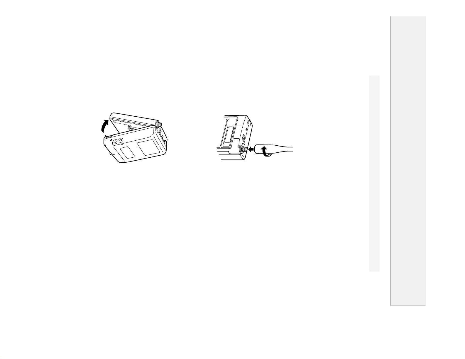
1
Attach the EDH-27 to the DJ-X2.
Hook the upper catches of EDH-27 in
the slots at the top of the DJ-X2, and
then attach the bottom as shown in
the illustration on the left.
Page 8

8
2
Connect the AC adapter's plug to the external power supply jack on the
EDH-27.
3
Connect to the AC outlet.
Recharging lamp on the EDH-27 lights, and recharging starts.
Tip
· It takes about 2 hours to fully charge the battery. (The required time depends
on the condition of the lithium-ion battery.)
· Irrespective of the position of the battery selection switch, the lithium-ion battery
will be charged.
· Normally, the lithium-ion battery can be charged up to 500 times.
Caution!
· Turn the DJ-X2's power OFF before recharging the lithium-ion battery.
· Disconnect the AC adapter from the outlet while not using it.
· Never charge the battery of other manufacturers products with this AC
adapter.
· Never short-circuit the recharging terminals with metal objects. The
recharger can be damaged.
· The recharger does not work when voltage from the outlet is extremely
low.
· Charging should be conducted in a temperature range of 0° to 40°C. (32° to
104°F)
Page 9

9
■
Loading the Batteries
AA batteries may be used instead of
the internal lithium-ion battery.
Load three AA batteries into the bat-
tery case with recharger (EDH-27) as
shown on the left.
Caution!
· Do not reverse the polarity of the batteries.
· Use new batteries of the same type and brand.
Tip
The following functions extend the battery life.
Auto power off (P.42), Battery save (P.41)
Page 10
1
Chapter
Names and Functions of Parts
1
Names and Functions of Parts
10
External View
The illustrations below are the DJ-X2 with the battery case and recharger
(EDH-27) attached.
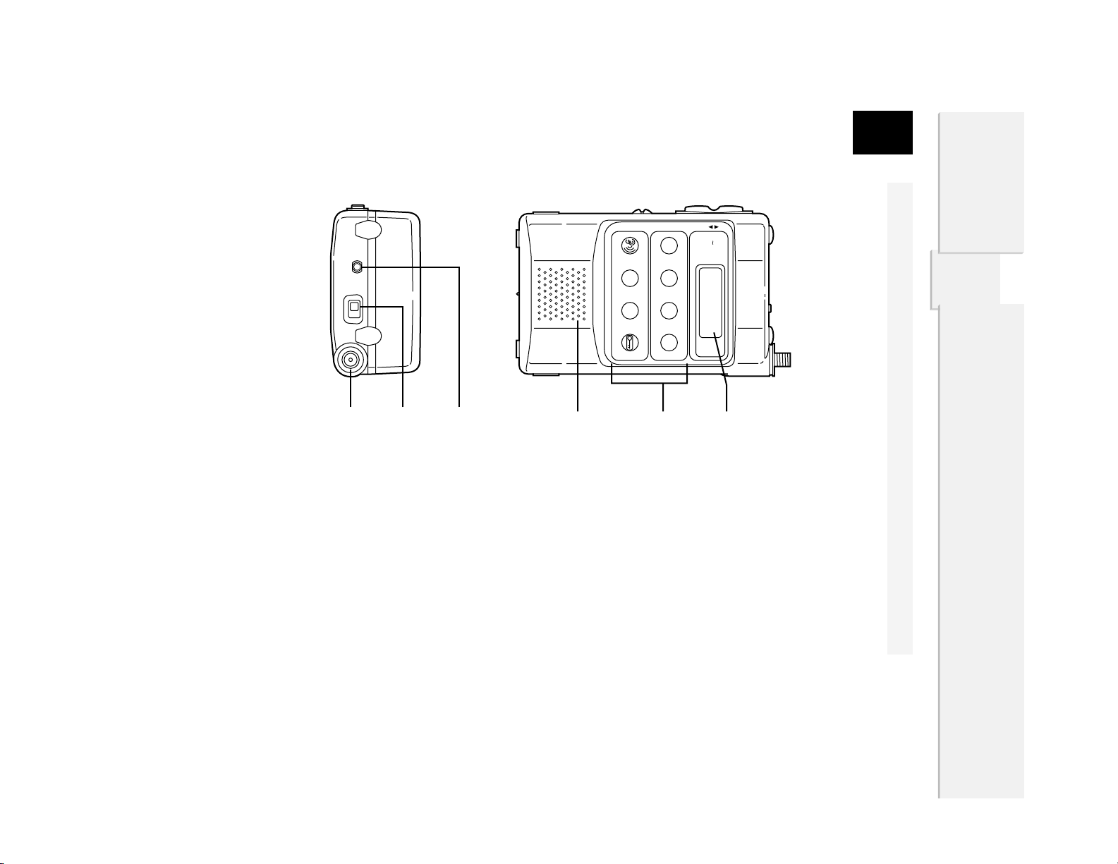
■
Front
■
Top
Earphone jack
For connection of the included earphone.
Power switch
For switching power ON and OFF. (P.14)
Antenna connector
For connecting the included antenna.
(P.7)
V/P/M
RXFREQUENCY
0.51000MHz
700MEMORY
CHANNELS
MW
MONI
SCRT
Lithium-ionBATTERYINSIDE
10MHz
BANK
FUNC
ENTER
PS
STEP/SKIP
1MHz
WIDEBANDCOMMUNICATIONRECEIVERDJ-X2
ANT
SCAN
X2
MODE
VOL/SQL
SET
BATTERY・・EXTERNAL DOWN UP
Display
Displays the frequency and other infor-
mation. (P.13)
Keyboard
For changing the mode and various set-
tings. (P.12)
Speaker
Thin built-in speaker
Page 11
arts
11
1
Names and Functions of Parts
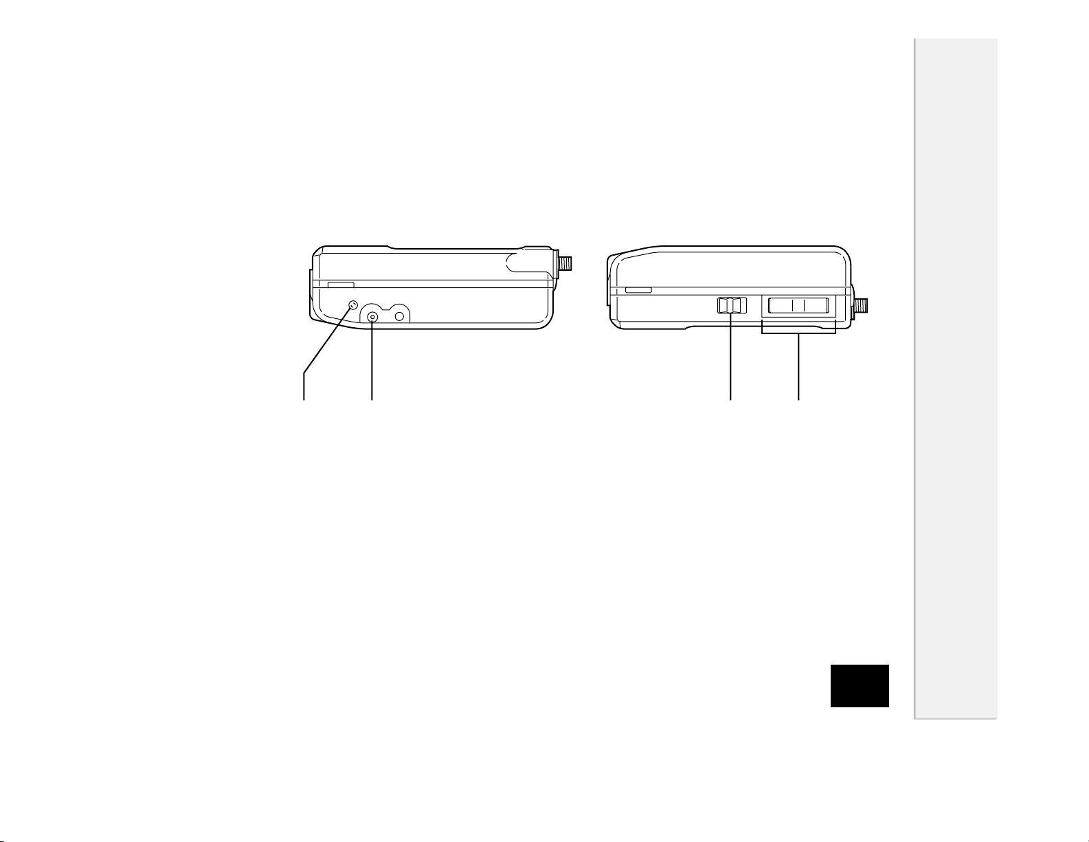
■
Side
DC-IN
Terminal for connecting the AC adapter
when recharging the internal battery.
Recharging Lamp
Lights when recharging the internal
lithium-ion battery.
[▲ / ▼] keys
For increasing/decreasing the frequen-
cy, and various settings.
Battery selection switch
For switching between internal and exter-
nal (EDH-27) batteries.
Page 12
1
Names and Functions of Parts
12
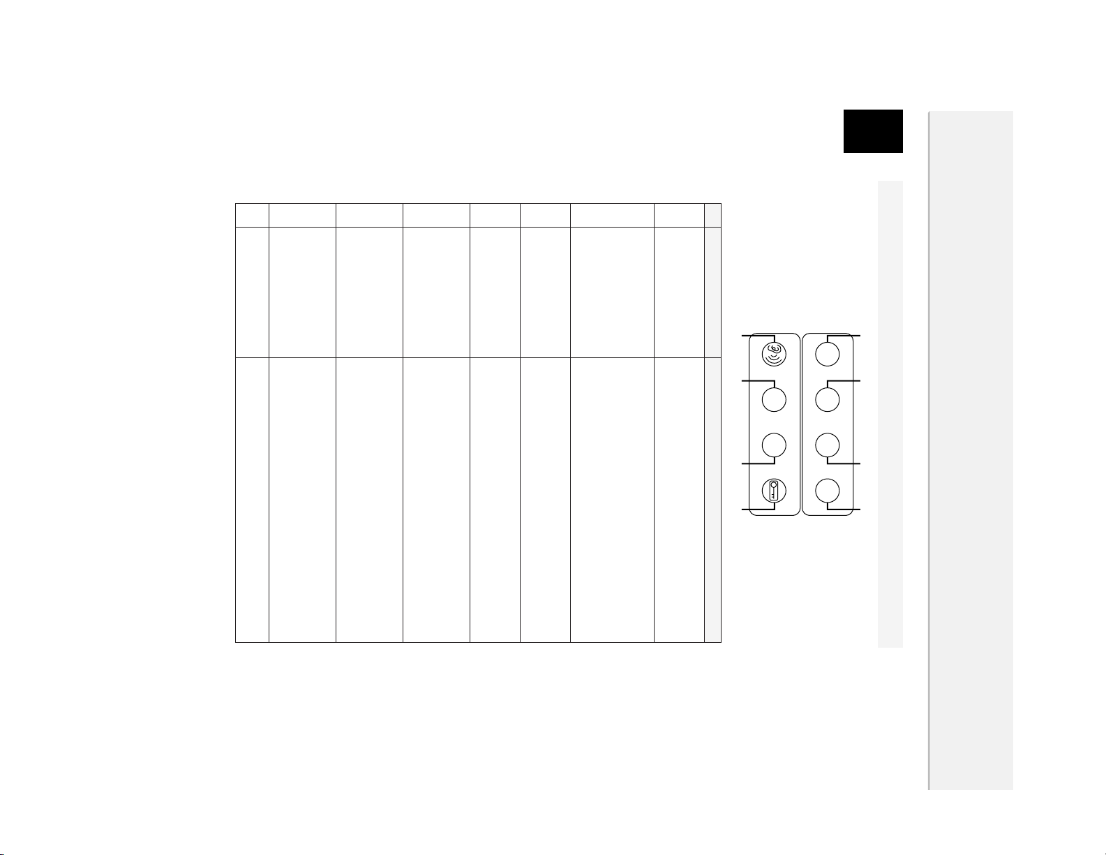
Keyboard
"F" appears on the display when you press the [FUNC/ENTER] key.
In Easy mode, the [FUNC/ENTER] key is not available except for Keylock.
Key Function
Switches the operating mode. (P.17)
When "F" is displayed, programs and clears the
memory channels. (P.30)
In VFO mode, pressing the [▲/▼] while this key
is held down increases/decreases the frequen-
cy by 1 MHz-step. (P.18)
When "F" is displayed, switches the type of
antenna. (P.33)
Executes scanning. (P.19)
When "F" is displayed, switches the modulation
mode. (P.34)
Adjusts the audio volume and squelch level. (P.15)
When "F" is displayed, switches the item in the
setting mode. (P.38)
Squelch unmutes while this key is held down.
(P.16)
When "F" is displayed, used for descrambling .
(P.37)
In VFO mode, pressing the [▲/▼] while this key
is held down increases/decreases the frequency
by 10 MHz-step. (P.18)
Switches the preset and memory bank.
Used for selecting the channel of the program
scan function, and starting it. (P.20)
When "F" is displayed, sets the tuning step and
memory skip. (P.35,36)
Used for starting and selecting various settings.
Locks key operation. (P.24)
[V/P/M (MW)] key
[1MHz (ANT)] key
[SCAN (MODE)] key
[VOL/SQL(SET)] key
[MONI (SCRT)] key
[10MHz (BANK)] key
[PS(STEP/SKIP)]
key
[FUNC/ENTER] key
①
②
③
④
⑤
⑥
⑦
⑧
V/P/M 1MHz SCAN VOL/SQL
MW ANT MODE
SET
MONI 10MHz PS FUNC
SCRT BANK STEP/SKIP ENTER
① ② ③ ④
⑤ ⑥ ⑦ ⑧
Page 13
13
1
Names and Functions of Parts
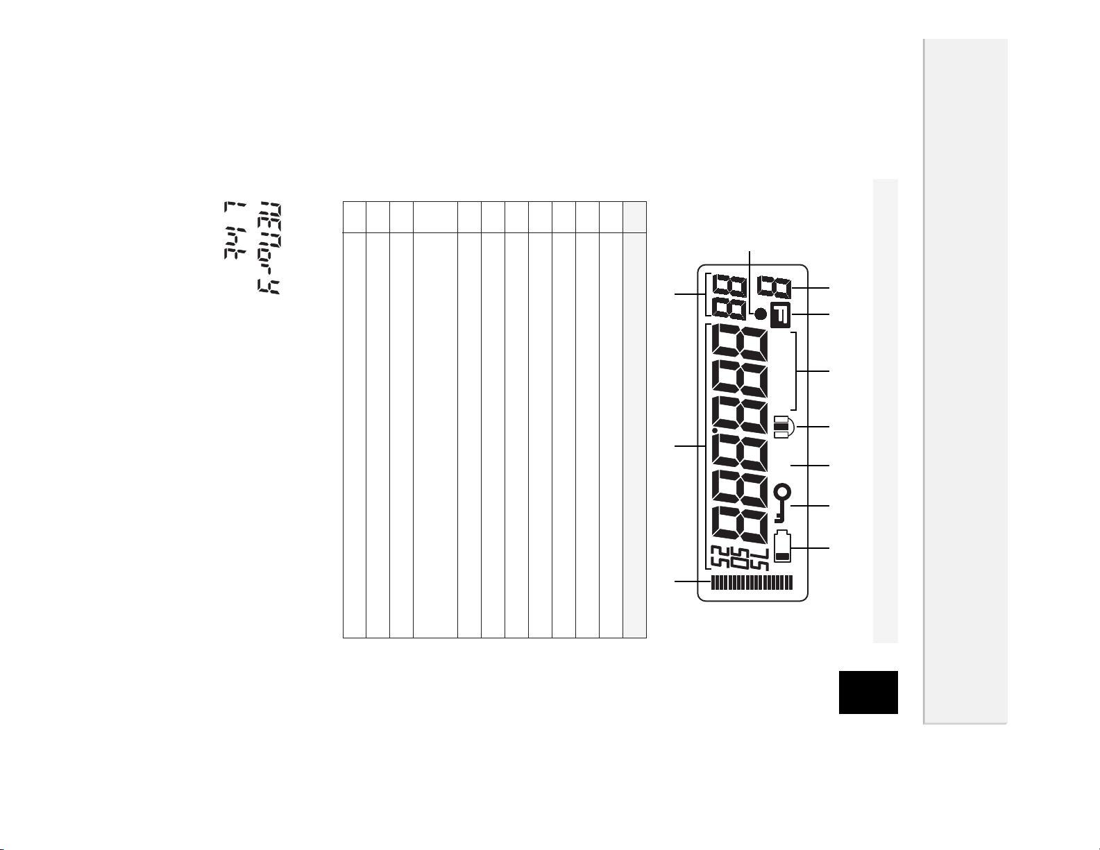
Display
In the illustration below, all indications are displayed.
Some letters cannot be displayed correctly (for example, "M" or "K"), and capital
letters and small letters may be mixed in a word. Refer to the following exam-
ples.
···········MEMory
····················LInk
Descriptions
Displays the bank No. of programmed memory.
Appears when you press the [FUNC/ENTER] key.
Displays the modulation mode.
Appears when executing Memory skip.
Appears when the Attenuator is ON.
Appears when the keys are locked.
Appears when the battery is exhausted.
Appears when using the bugging detector.
Flashes when descrambling.
Displays the channel No. of programmed memory.
Displays the frequency and value of various settings.
Displays the relative signal strength.
①
②
③
④
⑤
⑥
⑦
⑧
⑨
⑩
⑪
WFMAM ATT
①
⑨
⑧
⑪
② ③ ④ ⑤ ⑥ ⑦
⑩
Page 14
2
Chapter
Basic Operation
2
Basic Operation
14
Easy Mode and Expert Mode
The DJ-X2 has two operating profiles; Easy mode and Expert mode.
In Easy mode, key operations are limited, and you can operate the DJ-X2 easi-
ly. On the other hand, you can operate many useful functions in Expert mode.
If you are a beginner, operating in Easy mode is recommended. After under-
standing basic operations in Easy mode, you may try to operate other functions
in Expert mode.
(The factory setting is Easy mode.)
This chapter explains basic operation of the DJ-X2.
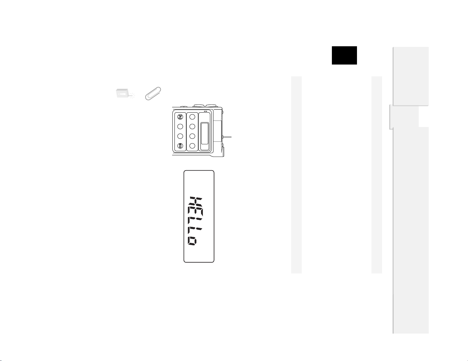
Power Switch
Before turning the power ON, check the position of the Battery selection switch.
EXTERNAL (upper) ·······················When using external batteries (EDH-27).
BATTERY (lower)···························When using the internal lithium-ion battery.
To turn the power ON, slide the power switch to "PWR ON" (right). "HELLo" will
appear on the display. (The indication may be different from the illustration
below depending on the version: North America or Europe.)
Tip
When the lithium-ion battery is charged, you can operate the DJ-X2 without the
battery case (EDH-27).
Caution!
Be sure to turn the power OFF when switching the Battery selection switch.
WIDE BAND COMMUNICATION RECEIVER DJ-X2
0.5
~
1000MHz
700 MEMORY
CHANNELS
RX FREQUENCY
X2
V / P / M 1MHz SCAN VOL/SQL
M W ANT MODE
SET
MONI 10MHz P S FUNC
SCRT BANK STEP/SKIP ENTER
DOWN UPBATTERY ・・ EXTERNAL
Lithium-ion
BATTERY INSIDE
Power switch
Page 15
15
2
Basic Operation
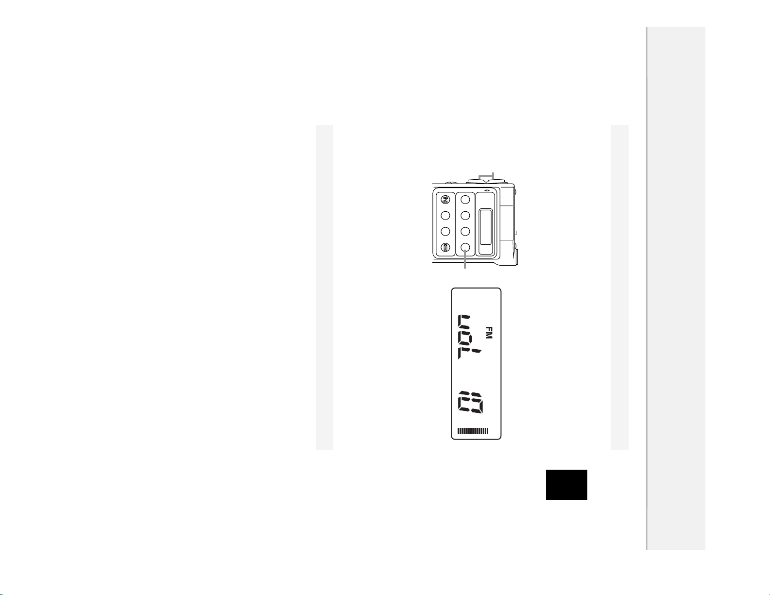
Adjusting the Audio Volume
1
Press the [VOL/SQL (SET)] key.
"voL" will appear on the display.
2
Adjust the audio volume by pressing [▲ / ▼] keys.
There are 21 levels of audio volume. (00-20) As the value increases, the
audio becomes louder.
3
Press the [FUNC/ENTER] key.
If the DJ-X2 makes no sound...
When the squelch closes, the DJ-X2 does not make sound even if you increase
the value of audio volume. For more information, see the next section.
Squelch
The squelch silences the DJ-X2 except for signals above a certain level.
Squelch eliminates noise when the DJ-X2 receives less than a certain level.
"To unmute the squelch" means that the DJ-X2 receives a signal and repro-
duces the sound.
Conversely, "to close the squelch" means that the DJ-X2 does not generate
audio because of insufficient signal level.
■
Adjusting the Squelch Level
You can specify the signal level at which the DJ-X2 unmutes by adjusting the
squelch level.
1
Press the [VOL/SQL (SET)] key twice.
"SqL" will appear on the display.
WIDE BAND COMMUNICATION RECEIVER DJ-X2
0.5
~
1000MHz
700 MEMORY
CHANNELS
RX FREQUENCY
X2
V / P / M 1MHz SCAN VOL/SQL
M W ANT MODE
SET
MONI 10MHz P S FUNC
SCRT BANK STEP/SKIP ENTER
DOWN UPBATTERY ・・ EXTERNAL
Lithium-ion
BATTERY INSIDE
2
1
Page 16

2
Basic Operation
16
2
Adjust the squelch level by pressing [▲ / ▼] keys.
There are 6 squelch levels. (0-5) A higher squelch level requires a stronger
signal to unmute the squelch.
3
Press the [FUNC/ENTER] or [VOL/SQL (SET)] key.
Tip
To keep the squelch open, set the squelch level to 0.
■
Monitor Function
The monitor function temporarily unmutes the squelch. This is useful when the
desired signal is weak or intermittent.
1
Press the [MONI (SCRT)] key.
The DJ-X2 unmutes the squelch while the key is held down.
2
To return to the set squelch level, release the [MONI (SCRT)] key.
The preparation for receiving a signal has been finished. Now, try to adjust the
frequency and receive a signal.
Next section explains the three operating modes of the DJ-X2.
WIDE BAND COMMUNICATION RECEIVER DJ-X2
0.5
~
1000MHz
700 MEMORY
CHANNELS
RX FREQUENCY
X2
V / P / M 1MHz SCAN VOL/SQL
M W ANT MODE
SET
MONI 10MHz P S FUNC
SCRT BANK STEP/SKIP ENTER
DOWN UPBATTERY ・・ EXTERNAL
Lithium-ion
BATTERY INSIDE
1
WIDE BAND COMMUNICATION RECEIVER DJ-X2
0.5
~
1000MHz
700 MEMORY
CHANNELS
RX FREQUENCY
X2
V / P / M 1MHz SCAN VOL/SQL
M W ANT MODE
SET
MONI 10MHz P S FUNC
SCRT BANK STEP/SKIP ENTER
DOWN UPBATTERY ・・ EXTERNAL
Lithium-ion
BATTERY INSIDE
2
1
Page 17

17
2
Basic Operation
Operating Mode
The DJ-X2 has three operating modes; VFO mode, Preset mode, and Memory
(MR) mode.
VFO mode ·····································VFO mode allows you to change the fre-
quency by [▲ / ▼] keys.
Preset mode··································The frequencies of AM radio, FM radio, and
TV have been set. You can call them up.
Memory mode ·······························You can call up and receive a previously
programmed frequency.
Tip
In Easy mode, you cannot program a frequency. To program a frequency, switch
the DJ-X2 to Expert Mode. For more information, see "Switching to Expert Mode"
(P.29) and "Memory Function" (P.30).
■
Switching Between Modes
Every press of the [V/P/M (MW)] key changes the operating mode as shown
below.
Tip
When nothing is programmed in Memory mode, Memory mode is skipped.
Preset mode Memory mode
VFO mode
V/P/M
MW
V/P/M
MW
V/P/M
MW
Page 18

2
Basic Operation
18
Setting the Frequency
■
In VFO mode
· Pressing the [▲ / ▼] keys increases or decreases the frequency by a tuning
step.
· To increase/decrease the frequency by 1MHz-step, hold down the [1MHz
(ANT)] key, and press the [▲ / ▼] keys.
· To increase/decrease the frequency by 10MHz-step, hold down the [10MHz
(BANK)] key, and press the [▲ / ▼] keys.
■
In Preset mode
1
Select a band by pressing the [10MHz (BANK)] key.
Every press of the [10MHz (BANK)] key changes the band as shown below:
AM radio ➝ FM radio ➝ TV ➝ AM radio ···.
2
Increase/ decrease the frequency by pressing the [▲ / ▼] keys.
Tip
· When selecting AM radio, "AM" appears on the upper part of the display.
· When selecting FM radio or TV, "WFM" appears on the upper part of the dis-
play, and the FM radio frequency or TV channel is displayed below.
WIDE BAND COMMUNICATION RECEIVER DJ-X2
0.5
~
1000MHz
700 MEMORY
CHANNELS
RX FREQUENCY
X2
V / P / M 1MHz SCAN VOL/SQL
M W ANT MODE
SET
MONI 10MHz P S FUNC
SCRT BANK STEP/SKIP ENTER
DOWN UPBATTERY ・・ EXTERNAL
Lithium-ion
BATTERY INSIDE
2
1
WIDE BAND COMMUNICATION RECEIVER DJ-X2
0.5
~
1000MHz
700 MEMORY
CHANNELS
RX FREQUENCY
X2
V / P / M 1MHz SCAN VOL/SQL
M W ANT MODE
SET
MONI 10MHz P S FUNC
SCRT BANK STEP/SKIP ENTER
DOWN UPBATTERY ・・ EXTERNAL
Lithium-ion
BATTERY INSIDE
Increases/decreases
the frequency.
Increases/decreases
by 1 MHz-step.
Increases/decreases
by 10 MHz-step.
Page 19

19
2
Basic Operation
Scan Function
The scan function periodically changes the frequency to serarch for a signal.
The DJ-X2 has four types of scan functions.
VFO scan ······································Scans the entire band in VFO mode.
Preset scan ···································Scans the entire band in Preset mode.
Program scan································Scans a specified range of frequencies. The
upper limit and lower limit of the range need
to be set in advance.
Memory scan ································Scans specified memory banks.
■
VFO scan
1
Switch to VFO mode by pressing the [V/P/M (MW)] key.
2
Press the [SCAN (MODE)] key.
VFO scan starts, and "." (decimal point) flashes on the display.
Scanning pauses when the DJ-X2 receives a signal.
■
Preset scan
1
Switch to Preset mode by pressing the [V/P/M (MW)] key.
2
Select AM radio, FM radio, or TV by pressing the [10MHz (BANK)] key.
WIDE BAND COMMUNICATION RECEIVER DJ-X2
0.5
~
1000MHz
700 MEMORY
CHANNELS
RX FREQUENCY
X2
V / P / M 1MHz SCAN VOL/SQL
M W ANT MODE
SET
MONI 10MHz P S FUNC
SCRT BANK STEP/SKIP ENTER
DOWN UPBATTERY ・・ EXTERNAL
Lithium-ion
BATTERY INSIDE
1
2
Flashes.
Page 20

2
Basic Operation
20
3
Press the [SCAN (MODE)] key.
Preset scan starts, and "." (decimal point) flashes on the display.
Scanning pauses when the DJ-X2 receives a signal.
■
Program scan
This function scans a specified range of frequencies. Before operating this
function, you need to specify the upper and lower frequency limits. These fre-
quencies are called a "Program channel", and the DJ-X2 has 20 pairs of pro-
gram channels.
Set the combination of upper and lower limits. (i.e. A00 and B00, or A01 and
B01) For more information, see "Programming a channel". (P.30)
To operate Program scan:
1
Switch to the VFO mode by pressing the [V/P/M (MW)] key.
2
Press the [PS (STEP/SKIP)] key.
A program channel will appear on the display.
3
Select a program channel by pressing the [▲ / ▼] keys.
Frequencies between A and B of the same No. will be scanned.
For example, if you select A01, scanning starts from A01 to B01.
Conversely, if you select B01, scanning starts from B01 to A01.
WIDE BAND COMMUNICATION RECEIVER DJ-X2
0.5
~
1000MHz
700 MEMORY
CHANNELS
RX FREQUENCY
X2
V / P / M 1MHz SCAN VOL/SQL
M W ANT MODE
SET
MONI 10MHz P S FUNC
SCRT BANK STEP/SKIP ENTER
DOWN UPBATTERY ・・ EXTERNAL
Lithium-ion
BATTERY INSIDE
Program channel
3
1
2,4
WIDE BAND COMMUNICATION RECEIVER DJ-X2
0.5
~
1000MHz
700 MEMORY
CHANNELS
RX FREQUENCY
X2
V / P / M 1MHz SCAN VOL/SQL
M W ANT MODE
SET
MONI 10MHz P S FUNC
SCRT BANK STEP/SKIP ENTER
DOWN UPBATTERY ・・ EXTERNAL
Lithium-ion
BATTERY INSIDE
Flashes.
1
2
3
Page 21

21
2
Basic Operation
4
Press the [PS (STEP/SKIP)] key.
Program scan starts. "." (decimal point) flashes on the display, and "PS"
appears on the display.
Scanning pauses when receiving a signal.
Tip
The tuning step and modulation mode of Program scan depends on the settings
in the VFO mode.
■
Memory scan
This function scans the specified banks or all banks in the Memory mode.
There are three types of Memory scan.
Bank scan ·····································Scans a specified bank only.
Bank link scan·······························Scans multiple banks. Up to five banks can
be linked. Link setting is required in
advance. For more information, see "Bank
link setting". (P.39)
All-bank scan ································Scans banks 0 to 9.
To operate Memory scan:
1
In Memory mode, press the [SCAN (MODE)] key.
Type of Memory scan will appear on the display.
2
Select a type of Memory scan by pressing the [▲ / ▼] keys.
MEMory : Bank scan
LInk : Bank link scan
ALL : All-bank scan
If you select Bank scan, the currently displayed bank in the Memory mode
will be scanned.
WIDE BAND COMMUNICATION RECEIVER DJ-X2
0.5
~
1000MHz
700 MEMORY
CHANNELS
RX FREQUENCY
X2
V / P / M 1MHz SCAN VOL/SQL
M W ANT MODE
SET
MONI 10MHz P S FUNC
SCRT BANK STEP/SKIP ENTER
DOWN UPBATTERY ・・ EXTERNAL
Lithium-ion
BATTERY INSIDE
Select a type of Memory scan.
2
1,3
Page 22

2
Basic Operation
22
3
Press the [SCAN (MODE)] key.
Bank scan starts, and "." (decimal point) flashes on the display.
The DJ-X2 stops scanning when receiving a signal.
Tip
The following are common to all the scans.
· Scanning direction depends on the direction of the last operation.(Except for
Program scan.)
· Scanning direction can be changed by pressing the [▲ / ▼] keys.
· To stop scanning, press any key except the [▲ / ▼] and [MONI (SCRT)] keys.
· If you press the [MONI (SCRT)] key while scanning, scanning pauses, and the
squelch unmutes. Releasing the [MONI (SCRT)] key resumes scanning.
· You can set the scan-resume conditions. For more information, see "Timer
scan/Busy scan setting". (P.41)
Page 23

23
2
Basic Operation
Bugging Detector
The DJ-X2 detects a bugging signal by scanning frequencies in the pro-
grammed memory banks. When a listening microphone is found, the DJ-X2
notifies you with its display.
Caution!
Be sure to remove the earphone when detecting bugging.
1
Hold down the [MONI (SCRT)] key, and turn the power ON.
"●" will appear on the display, and the DJ-X2 starts scanning according to
the set memory bank link.
When a bugging signal is found, "dC" flashes on the display, and scanning
stops.
Press the [VOL/SQL (SET)] key to adjust the audio volume.
Adjust the audio volume so that the howling noise sounds at an angle to the
DJ-X2, and detect the listening microphone. Be sure not to cover the speaker.
Flashes.
WIDE BAND COMMUNICATION RECEIVER DJ-X2
0.5
~
1000MHz
700 MEMORY
CHANNELS
RX FREQUENCY
X2
V / P / M 1MHz SCAN VOL/SQL
M W ANT MODE
SET
MONI 10MHz P S FUNC
SCRT BANK STEP/SKIP ENTER
DOWN UPBATTERY ・・ EXTERNAL
Lithium-ion
BATTERY INSIDE
1
Appears.
Page 24

2
Basic Operation
24
Cautions!
· Operate in a quiet environment where doors and windows are closed. It is
hard to find a listening microphone in a noisy environment.
· Depending on the modulation setting, this function may not work correctly.
· When the battery voltage is low, this function does not work normally. Be
sure to charge the internal lithium-ion battery completely, load new alka-
line batteries, or supply sufficient voltage from the DC power supply.
· Since this function detects a bugging signal by the presence or absence
of a howling noise, a loud sound may be emitted during detection, howev-
er, it is not a malfunction.
· Detection area is approximately 15 - 20 square meters (18 - 24 square
yards) depending on the type of listening microphone.
How do you stop detecting?
Turn the power OFF, then hold down the [MONI (SCRT)] key and turn the
power ON.
Keylock
To prevent incorrect or unauthorized operations, you can lock the keys.
The following operations can be used while the keylock is ON.
· Monitor function
· Adjusting the audio volume and squelch
· Canceling the keylock
To lock the keys:
1
Hold down the [FUNC/ENTER] key for a second.
The key lock will turn ON, and the key icon will appear on the display.
How do you cancel the keylock?
Hold down the [FUNC/ENTER] key for a second while the keylock is ON.
The keylock will turn OFF, and the key icon will disappear.
WIDE BAND COMMUNICATION RECEIVER DJ-X2
0.5
~
1000MHz
700 MEMORY
CHANNELS
RX FREQUENCY
X2
V / P / M 1MHz SCAN VOL/SQL
M W ANT MODE
SET
MONI 10MHz P S FUNC
SCRT BANK STEP/SKIP ENTER
DOWN UPBATTERY ・・ EXTERNAL
Lithium-ion
BATTERY INSIDE
1
Appears.
Page 25

25
2
Basic Operation
Resetting
You can reset the programmed memory channels and settings.
There are two types of reset.
Partial reset (PArt) ·························Programmed memory channels remain, and
other settings are reset.
All reset (ALL) ·······························All the memory channels and settings are
reset. (Preset channels cannot be reset.)
To reset:
1
Hold down the [FUNC/ENTER] key, and turn the power ON.
"CAnCEL " will appear on the display.
2
Select a type of reset by pressing the [▲ / ▼] key.
Select from "CAnCEL", "PArt", and "ALL". To cancel resetting, select
"CAnCEL".
3
Press the [FUNC/ENTER] key.
Reset will be executed.
Tip
· In Easy mode, only Partial reset is available.
· When resetting in Expert mode, the DJ-X2 will return to Easy mode.
WIDE BAND COMMUNICATION RECEIVER DJ-X2
0.5
~
1000MHz
700 MEMORY
CHANNELS
RX FREQUENCY
X2
V / P / M 1MHz SCAN VOL/SQL
M W ANT MODE
SET
MONI 10MHz P S FUNC
SCRT BANK STEP/SKIP ENTER
DOWN UPBATTERY ・・ EXTERNAL
Lithium-ion
BATTERY INSIDE
3
1
2
Select a type of reset.
Page 26

2
Basic Operation
26
Cloning
When using the clone function, all the settings of one DJ-X2 (master) can be
copied to another DJ-X2 (slave).
To operate the clone function:
1
Turn OFF both DJ-X2s.
2
Connect the earphone jacks on both master and slave DJ-X2s with the
cloning cable.
3
Hold down the [VOL/SQL (SET)] key of the master DJ-X2, and turn it ON.
"CLonE" will appear on the display.
4
Turn the slave DJ-X2 ON.
WIDE BAND COMMUNICATION RECEIVER DJ-X2
0.5
~
1000MHz
700 MEMORY
CHANNELS
RX FREQUENCY
X2
V / P / M 1MHz SCAN VOL/SQL
M W ANT MODE
SET
MONI 10MHz P S FUNC
SCRT BANK STEP/SKIP ENTER
DOWN UPBATTERY ・・ EXTERNAL
Lithium-ion
BATTERY INSIDE
1
(Master)
Connect to the earphone
jack of the DJ-X2.
Master unit
Connect to the earphone
jack of the DJ-X2
Slave unit.
Page 27

27
2
Basic Operation
5
Press the [▲] key of the master DJ-X2.
Cloning starts. "Sd □□□□" appears on the master DJ-X2's display, and
"Ld □□□□"appears on the slave DJ-X2's display.
When cloning is completed, "PASS" appears on both DJ-X2s' displays.
To return to normal operation, turn the power OFF, and then turn ON again.
Caution!
· Do not disconnect the cable while cloning.
· Be advised that all data in the slave DJ-X2 will be updated if cloning is exe-
cuted.
· If you disconnect the cable or turn OFF the other DJ-X2 after "PASS" was
displayed, "CoMErr" will appear on the display, however cloning has been
executed normally.
If "Error" appears on the display...
If incorrect data is transmitted while cloning, "Error" will appear on both DJ-X2s'
displays.
To try again, press the [▲] key of the master DJ-X2.
If "CoMErr" appears on the display...
If a communication error occurs, "CoMErr" will appear on both DJ-X2s' displays.
To try again, press the [▲] key of the master DJ-X2.
To copy the data to another slave DJ-X2
After completing one cloning operation, connect the master DJ-X2 to another
slave DJ-X2, and then press the [▲] key of the master DJ-X2.
(Slave)(Master)
Page 28

2
Basic Operation
28
Battery Indication
When the battery is exhausted, the battery icon appears on the display.
If the icon appears, battery power will soon be depleted.
Load new batteries or recharge the internal lithium-ion battery.
Appears.
Page 29

29
3
Operating in Expert Mode
The DJ-X2 has two operating profiles; Easy mode and Expert mode.
In Expert mode, the following functions are available:
Memory Function (P.30)
Setting the Antenna (P.33)
Selecting the Modulation Mode (P.34)
Setting the Tuning Step (P.35)
Memory Skip (P.36)
Descrambling (P.37)
Operational Settings (P.38)
This section explains how to use the additional functions in the Expert mode.
Switching to Expert Mode
When shipped, the DJ-X2 is set to Easy Mode.
To switch to Expert mode:
1
Hold down the [V/P/M (MW)] key, and turn the power ON.
"EASy" will appear on the display.
2
Press the [▲ / ▼] keys.
The display will change to "Pro".
Every press of the [▲ / ▼] key changes the display as shown below.
"Pro" ➝ "EASy" ➝ "Pro" ···
Select "Pro".
3
Press the [FUNC/ENTER] key.
The DJ-X2 will switch to Expert mode.
How to return to Easy mode?
At step-2 above, select "EASy", and press the [FUNC/ENTER] key.
WIDE BAND COMMUNICATION RECEIVER DJ-X2
0.5
~
1000MHz
700 MEMORY
CHANNELS
RX FREQUENCY
X2
V / P / M 1MHz SCAN VOL/SQL
M W ANT MODE
SET
MONI 10MHz P S FUNC
SCRT BANK STEP/SKIP ENTER
DOWN UPBATTERY ・・ EXTERNAL
Lithium-ion
BATTERY INSIDE
2
1
3
Select "Pro".
3
Chapter
Operating in Expert Mode
Page 30

3
Operating in Expert Mode
30
Tip
The settings you change in Expert mode are valid even after returning to Easy
mode, however, they cannot be changed in Easy mode.
Memory Function
This function allows you to program the frequently used frequencies, and call
them up. A programmed frequency is called a channel.
The DJ-X2 has four types of memory functions; Memory bank channel, Program
channel, Search-pass memory channel, and Priority channel.
■
Types of Memory
Memory bank channel ····················The channel which is called up in Memory
mode. The DJ-X2 has 700 Memory bank
channels (70 channels 5 10 banks). You
can call up a frequently used frequency
easily.
Program channel·····························A channel which is used for Program scan.
You can program 20 pairs of frequency
ranges (upper and lower limits). (P.20)
Search-pass memory channel ········If you program a frequency which you do
not want to use, it will be skipped when exe-
cuting VFO scan and Program scan. You
can program up to 100 "Skip" channels.
Priority channel ·······························The channel which is used for Priority monitor-
ing functions. You can program up to 8 chan-
nels.(P.43)
Tip
When you program a frequency in Search-pass memory channel, you
have to set the mode in FM. Please refer to "Selecting the Modulation
Mode" (page 34) for the setting.
■
Programming a channel
To program the channel:
1
In VFO mode, select the frequency which you want to program.
2
Press the [FUNC/ENTER] key.
"F" will appear on the display.
Page 31

31
3
Operating in Expert Mode
3
Select a bank by pressing the [10MHz (BANK)] key.
Every press of the [10MHz (BANK)] key changes the bank at the upper left
on the display as shown below.
0 ➝ 1 ➝ 2 ··· ➝ 9 ➝ A ➝ P ➝ J ➝ 0 ···
Each bank No. corresponds to the following bank.
0 - 9 : For Memory channel
A, B : For Program scan channel
P : For Priority channel
J : For Search-pass memory channel
Select a bank according to the use.
4
Select a channel by pressing the [▲ / ▼] keys.
According to the type of bank, available channels are different as shown
below.
Bank 0 - 9 : 00 - 69
Bank A, B : A00 - B19
Bank P : 00 - 07
Bank J : 00 - 99
5
Press the [V/P/M (MW)] key.
The setting will be completed.
Tip
· It is not possible to increase the number of memory channels.
· It is not possible to overwrite the memory in the default setting. For more infor-
mation, see "OV (Overwrite) setting" (P.43).
WIDE BAND COMMUNICATION RECEIVER DJ-X2
0.5
~
1000MHz
700 MEMORY
CHANNELS
RX FREQUENCY
X2
V / P / M 1MHz SCAN VOL/SQL
M W ANT MODE
SET
MONI 10MHz P S FUNC
SCRT BANK STEP/SKIP ENTER
DOWN UPBATTERY ・・ EXTERNAL
Lithium-ion
BATTERY INSIDE
5
Channel No.
4
WIDE BAND COMMUNICATION RECEIVER DJ-X2
0.5
~
1000MHz
700 MEMORY
CHANNELS
RX FREQUENCY
X2
V / P / M 1MHz SCAN VOL/SQL
M W ANT MODE
SET
MONI 10MHz P S FUNC
SCRT BANK STEP/SKIP ENTER
DOWN UPBATTERY ・・ EXTERNAL
Lithium-ion
BATTERY INSIDE
2
3
F appears.
Bank No.
Page 32

3
Operating in Expert Mode
32
■
Selecting a channel
To call up a frequency programmed in a channel:
1
Switch to the Memory mode by pressing the [V/P/M (MW)] key.
2
Select a bank by pressing the [10MHz (BANK)] key.
3
Select a channel by pressing [▲ / ▼] keys.
It is not possible to select a channel which is not programmed.
■
Clearing a channel
To clear a channel:
1
Switch to the Memory mode by pressing the [V/P/M (MW)] key.
2
Select a channel which you want to clear.
3
Press the [FUNC/ENTER] key.
"F" will appear on the display.
4
Press the [V/P/M (MW)] key.
The channel will be cleared.
Tip
You can clear all the programmed channels at one time. For more information,
see "Resetting" (P.25).
WIDE BAND COMMUNICATION RECEIVER DJ-X2
0.5
~
1000MHz
700 MEMORY
CHANNELS
RX FREQUENCY
X2
V / P / M 1MHz SCAN VOL/SQL
M W ANT MODE
SET
MONI 10MHz P S FUNC
SCRT BANK STEP/SKIP ENTER
DOWN UPBATTERY ・・ EXTERNAL
Lithium-ion
BATTERY INSIDE
Channel No.
3
2
Bank No.
Page 33

33
3
Operating in Expert Mode
Setting the Antenna
You can select the antenna depending on the frequency you wish to receive.
The DJ-X2 has three types of antennas.
External antenna ···························The SMA antenna attached to the DJ-X2.
Earphone antenna·························The earphone's cord performs the role of
antenna.
Bar antenna···································The internal antenna which receives AM
radio. (DJ-X2T: 530 kHz - 1710 kHz (step:
10 kHz), DJ-X2E: 522 kHz - 1620 kHz (step:
9 kHz))
■
When receiving any frequency except AM radio
1
Press the [FUNC/ENTER] key.
"F" will appear on the display.
2
Press the [1MHz (ANT)] key.
"EAr on/oF" (which shows the status of the earphone antenna) will appear on
the display.
3
Select ON or OFF by pressing the [▲ / ▼] keys.
EAr on : Receives with the earphone antenna.
EAr oF : Receives with the external antenna.
(The default setting is OFF.)
4
Press the [FUNC/ENTER] key.
The setting will be completed.
Tip
When using the earphone antenna, a signal may be unstable depending on the
position of the earphone cord.
WIDE BAND COMMUNICATION RECEIVER DJ-X2
0.5
~
1000MHz
700 MEMORY
CHANNELS
RX FREQUENCY
X2
V / P / M 1MHz SCAN VOL/SQL
M W ANT MODE
SET
MONI 10MHz P S FUNC
SCRT BANK STEP/SKIP ENTER
DOWN UPBATTERY ・・ EXTERNAL
Lithium-ion
BATTERY INSIDE
Select ON/OFF.
3
2
1,4
Page 34

3
Operating in Expert Mode
34
■
When receiving AM radio
At steps 1 and 2 mentioned on the previous page, "bAr on/oF" (which shows
the status of the bar antenna) appears on the display.
bAr on : Receives with the bar antenna.
bAr oF : Receives with the external antenna or earphone antenna.
(The default setting is ON.)
Pressing the [FUNC/ENTER] key completes the setting.
Selecting the Modulation Mode
You can select a modulation mode from AM, FM, and WFM.
To select :
1
Press the [FUNC/ENTER] key.
"F" will appear on the display.
2
Choose modulation mode by pressing the [SCAN (MODE)] key.
Every press of the [SCAN (MODE)] key changes the display as shown
below.
AM ➝ FM ➝ WFM ➝ AM ···
3
Press the [FUNC/ENTER] key.
The setting will be completed.
If the modulation mode cannot be changed...
When the tuning step is set to AUTO, you cannot select modulation. For more
information, see the next section "Setting the Tuning Step".
WIDE BAND COMMUNICATION RECEIVER DJ-X2
0.5
~
1000MHz
700 MEMORY
CHANNELS
RX FREQUENCY
X2
V / P / M 1MHz SCAN VOL/SQL
M W ANT MODE
SET
MONI 10MHz P S FUNC
SCRT BANK STEP/SKIP ENTER
DOWN UPBATTERY ・・ EXTERNAL
Lithium-ion
BATTERY INSIDE
2
F appears. Select AM, FM, or WFM.
1,3
Page 35

35
3
Operating in Expert Mode
Setting the Tuning Step
The tuning step sets the increment/decrement of each press of the [▲ / ▼]
keys when adjusting the frequency in VFO mode.
To set the tuning step:
1
Switch to VFO mode by pressing the [V/P/M (MW)] key.
2
Press the [FUNC/ENTER] key.
"F" will appear on the display.
3
Press the [PS (STEP/SKIP)] key.
The currently selected tuning step will appear on the display. The default
setting is AUTO.
4
Select a tuning step by pressing the [▲ / ▼] keys from the followings.
5, 6.25, 8.33, 10, 12.5, 15, 20, 25, 30, 50, 100, and AUTO. (unit : kHz)
5
Press the [FUNC/ENTER] key.
The setting will be completed.
Tip
· When AUTO is selected, the suitable tuning step and modulation mode are
automatically selected. When AUTO is selected, you cannot change the modu-
lation mode.
· The tuning step in AM radio is fixed to 9 kHz (DJ-X2E).
WIDE BAND COMMUNICATION RECEIVER DJ-X2
0.5
~
1000MHz
700 MEMORY
CHANNELS
RX FREQUENCY
X2
V / P / M 1MHz SCAN VOL/SQL
M W ANT MODE
SET
MONI 10MHz P S FUNC
SCRT BANK STEP/SKIP ENTER
DOWN UPBATTERY ・・ EXTERNAL
Lithium-ion
BATTERY INSIDE
F appears.
4
3
Tuning step
2,5
Page 36

3
Operating in Expert Mode
36
Memory Skip
This function is for skipping the specified memory channel(s) when executing
the Memory scan.
To set the memory channel which you want to skip:
1
Switch to Memory mode by pressing the [V/P/M (MW)] key.
2
Call up the memory channel you want to skip.
3
Press the [FUNC/ENTER] key.
"F" will appear on the display.
4
Press the [PS (STEP/SKIP)] key.
The setting will be completed.
How do you cancel the memory skip?
Call up the memory channel to cancel, and then operate steps 3 and 4 above.
WIDE BAND COMMUNICATION RECEIVER DJ-X2
0.5
~
1000MHz
700 MEMORY
CHANNELS
RX FREQUENCY
X2
V / P / M 1MHz SCAN VOL/SQL
M W ANT MODE
SET
MONI 10MHz P S FUNC
SCRT BANK STEP/SKIP ENTER
DOWN UPBATTERY ・・ EXTERNAL
Lithium-ion
BATTERY INSIDE
3
Appears.
4
Page 37

37
3
Operating in Expert Mode
Descrambling
This function returns scrambled voice to normal reception.
To descramble:
1
Select the frequency of the scrambled voice.
2
Press the [FUNC/ENTER] key.
"F" will appear on the display.
3
Press the [MONI (SCRT)] key.
Descrambling function starts operating, and "●" at the upper left of the dis-
play flashes.
Decode No. for scrambling will appear on the display.
You can change the decode No. by pressing the [▲ / ▼] keys.
4
Select a decode No. by pressing the [▲ / ▼] keys.
Select a decode No. from 01 to 17. Select the No. which allows you to rec-
ognize the voice.
Tip
Pressing the [FUNC/ENTER] key allows you to descramble the voice using the
specified decode No., and change the frequency at the same time.
How do you cancel the descrambling function?
Press the [FUNC/ENTER] key, then the [MONI (SCRT)] key.
WIDE BAND COMMUNICATION RECEIVER DJ-X2
0.5
~
1000MHz
700 MEMORY
CHANNELS
RX FREQUENCY
X2
V / P / M 1MHz SCAN VOL/SQL
M W ANT MODE
SET
MONI 10MHz P S FUNC
SCRT BANK STEP/SKIP ENTER
DOWN UPBATTERY ・・ EXTERNAL
Lithium-ion
BATTERY INSIDE
Flashes.
2
4
3
Decode No.
Page 38

3
Operating in Expert Mode
38
Operational Settings
This function allows you to customize the DJ-X2 for your particular application.
The following items can be set in the setting mode.
ATT (Attenuator) function (P.39)
Bank link setting (P.39)
Beep function (P.40)
Lamp function (P.40)
Timer scan/Busy scan setting (P.41)
BS (Battery save) function (P.41)
APO (Auto power off) function (P.42)
Bugging detector sensitivity setting (P.42)
OV (Overwrite) setting (P.43)
PRIO (Priority) Watch (P.43)
■
Setting each item
All the items of the setting mode are set by the same operation.
1
Press the [FUNC/ENTER] key.
"F" will appear on the display.
2
Press the [VOL/SQL (SET)] key.
The item name will be displayed.
3
Select an item by pressing the [VOL/SQL (SET)] key.
Each press of the [VOL/SQL (SET)] key changes the item as shown below.
"Att" ➝ "bL" ➝ "bEEP" ➝ "LP" ➝ "tIMEr" (or "bUSy") ➝ "bS" ➝ "APO" ➝ "tAP"
➝ "ov" ➝ "Pr" ➝ "Att" ···
4
Change the value or setting by pressing the [▲ / ▼] keys.
5
Press the [FUNC/ENTER] key.
The setting will be completed.
For detailed information of each item, see the following.
WIDE BAND COMMUNICATION RECEIVER DJ-X2
0.5
~
1000MHz
700 MEMORY
CHANNELS
RX FREQUENCY
X2
V / P / M 1MHz SCAN VOL/SQL
M W ANT MODE
SET
MONI 10MHz P S FUNC
SCRT BANK STEP/SKIP ENTER
DOWN UPBATTERY ・・ EXTERNAL
Lithium-ion
BATTERY INSIDE
4
1,5
2,3
Item
F appears.
Page 39

39
3
Operating in Expert Mode
■
ATT (Attenuator) function
This function attenuates strong signals on nearby channels.
Use this function when the received signal is influenced by a strong signal.
ATT function attenuates about 20 dB in received signal.
Select "Att" in the setting mode.
· Select ON/OFF by pressing the [▲ / ▼] keys.
· The default setting is OFF.
■
Bank link setting
This is the setting for the "Bank link scan", which scans specified multiple
banks.
You can select up to 5 banks from 10 programmed banks.
Select "bL" in the setting mode.
· Select Bank link No. by pressing the [▲ / ▼] keys.
· Select a bank to link by pressing the [10MHz (BANK)] key. One bank can be
assigned to each bank link No. 0-4.
Tip
· When only one bank is set to the bank link, if you execute the bank link scan,
only one bank will be scanned.
· For more information, see "Memory Scan". (P.21)
· Bugging detector detects the listening microphone from bank-linked memories.
When using the bugging detector, corresponding banks must be linked.
When using the bugging detector, bank No. 0 must be included in bank link
setting.
Bank No.Bank link No.
Select ON/OFF.
Page 40

3
Operating in Expert Mode
40
■
Beep function
The beep sound which sounds when operating keys on the DJ-X2 can be
turned OFF.
Select "bEEP" in the setting mode.
· Select ON/OFF by pressing the [▲ / ▼] keys.
· The default setting is ON.
■
Lamp function
This function sets the display backlight ON or OFF.
When ON is selected, an operation of any key turns ON the backlight, and it
automatically turns OFF after 5 seconds.
Select "LP" in the setting mode.
· Select ON/OFF by pressing the [▲ / ▼] keys.
· The default setting is OFF.
· Batter life may decrease when set to ON.
Select ON/OFF.
Select ON/OFF.
Page 41

41
3
Operating in Expert Mode
■
Timer scan/Busy scan setting
You can set the scan-resume condition.
While executing the scan, if the DJ-X2 receives a signal, scanning will pause.
You can set the timing that the DJ-X2 restarts scanning.
Timer scan (tIMEr)·························Restarts after five-second stop, even while
still receiving a signal.
Busy scan (bUSy) ·························Restarts when the DJ-X2 does not receive a
signal.
Select "tIMEr" or "bUSy" in the setting mode.
· Select Timer/Busy scan by pressing the [▲ / ▼] keys.
· The default setting is Timer scan.
■
BS (Battery save) function
This function extends battery life.
If there is no key operation for five seconds, the internal power rapidly cycles
between ON and OFF.
Select "bS" in the setting mode.
· Select ON/OFF by pressing the [▲ / ▼] keys.
· The default setting is ON.
Select ON/OFF.
Select Timer/Busy scan.
Page 42

3
Operating in Expert Mode
42
■
APO (Auto power off) function
This function automatically turns the power OFF if there is no key operation for a
specified period of time.
Select the time from 30, 60, 90 minutes, and OFF. When OFF is selected, this
function does not work.
Select "APO" in the setting mode.
· Select ON/OFF by pressing the [▲ / ▼] keys.
· The default setting is OFF.
· APO function does not work while scanning.
■
Bugging detector sensitivity setting
You can select the sensitivity when detecting a bugging.There are 5 sensitivity
levels; 1 - 5. 1 is the highest.
Select "tAP" in the setting mode.
· Select the sensitivity by pressing the [▲ / ▼] keys.
· The default setting is 3.
Select the sensitivity.
Select the time.
Page 43

43
3
Operating in Expert Mode
■
OV (Overwrite) setting
To prevent from overwriting a memory channel by mistake, set the Overwrite set-
ting.
Select "ov" in the setting mode.
· Select ON/OFF by pressing the [▲ / ▼] keys.
"ov on" : Overwriting enabled
"ov oF" : Overwriting disabled
· The default setting is OFF.
■
PRIO (Priority) watch
This function monitors two frequencies alternately.
Every five seconds, the DJ-X2 momentarily switches from the frequency in the
VFO mode to the frequency in the priority channel.
Select "Pr" in the setting mode.
· Select a priority channel No. from 0 to 7 by pressing the [▲ / ▼] keys.
· The default setting is OFF.
· Scan is not available during priority watch.
· If the DJ-X2 received a signal of the priority channel, receiving time will be
extended for 2 seconds.
How do you cancel the priority watch?
Press the [SCAN (MODE)], [PS (STEP/SKIP)], or [FUNC/ENTER] key during the
priority watch.
Priority channel
Select ON/OFF.
Page 44

4
Chapter
Appendices
4
Appendices
44
Troubleshooting
Please check the list below before concluding the DJ-X2 is faulty. If a problem
persists, reset the DJ-X2. This can sometimes correct erroneous operation.
Symptom Possible Cause Action
Recharge or exchange batter-
ies.
Check the position of battery
selection switch.
Adjust the volume.
Remove the earphone.
Adjust the squelch level or
turn OFF. Or press the [MONI
(SCRT)] key.
Adjust the squelch level or
turn OFF.
Turn the attenuator OFF.
Check the type of antenna,
and then switch.
Change the tuning step, and
adjust the frequency.
Select the suitable modulation
mode.
Recharge or exchange batter-
ies.
Turn OFF keylock
Turn the power OFF, then ON.
(If unit does not recover, reset.)
Recharge or exchange batter-
ies.
Dead battery
Incorrect position of
battery selection switch
Volume too low
Earphone connected
Squelch closed
Squelch level too high
Attenuator is ON
Incorrect antenna
selection (SMA, EAR,
BAR antenna)
Incorrect frequency
Incorrect modulation
mode
Dead battery
Keylock is ON
Incorrect operation of
CPU
Battery exhausted
Cannot turn the
power ON
No speaker audio
Low sensitivit
Unclear sound
Cannot set the
frequency etc.
Abnormal display
or operation
Page 45

45
4
Appendices
Specifications
■
General
Receiving range E : 0.522 - 999.995 MHz
T : 0.530 - 823.995 MHz
850.000 - 868.995 MHz
895.000 - 999.995 MHz
Modulation modes : FM, WFM, AM
Ant. impedance : 50Ω
Ant. terminal : SMA
Supply voltage : DC 3.8V (internal lithium-ion battery)
DC 4.5V (when using EDH-27)
Ground : Negative ground
Current consumption : Reception: approx. 80 mA
Battery save (1 : 4): approx. 25 mA
Temperature range : –10 - +60°C (+14 - +140°F)
Frequency stability : ±5 ppm (–10 - +60°C) (+14 - +140°F)
Dimension : 58 (W)✕90 (H)✕15 (D) mm (without projections)
(2.28 (W)✕3.54 (H)✕0.59 (D) in.)
Weight : Approx. 85 g (Lithium-ion battery inclusive)
(Approx. 3 oz.)
■
Receiver
System : Triple-conversion superheterodyne
First I.F. : 248.45 MHz
Second I.F. : 38.85 MHz
Third I.F. : 450 kHz
Selectivity : AM/FM –6 dB/12 kHz or over, –60 dB/30 kHz or less
WFM –6 dB/150 kHz or over
Sensitivity : FM/WFM 12 dB SINAD, AM 10 dB S/N
typ. FM : 30 - 108 0.63 µV (–4 dBµ)
136 - 222 0.40 µV (–8 dBµ)
222 - 470 0.50 µV (–6 dBµ)
470 - 770 0.56 µV (–5 dBµ)
770 -1000 0.71 µV (–3 dBµ)
WFM : 76 - 108 3.20 µV (10 dBµ)
175 - 222 2.20 µV ( 7 dBµ)
470 - 770 3.20 µV (10 dBµ)
AM : 0.5 - 1.62 7.10 µV (17 dBµ)
1.62 - 30 1.40 µV ( 3 dBµ)
108 - 136 2.00 µV ( 6 dBµ)
222 - 330 1.80 µV ( 5 dBµ)
Page 46

4
Appendices
46
Operation Chart
Function Key Operation Page
P.15
P.15
P.18
P.16
P.19
P.19
P.20
P.21
P.29
P.17
P.18
P.32
P.30
P.33
P.34
P.35
P.36
[VOL/SQL] key, Adjust by [▲/▼]
keys
[VOL/SQL] key, Adjust by [▲/▼]
keys
[▲/▼] keys
[1MHz (ANT)]+[▲/▼] keys
[10MHz (BANK)]+[▲/▼] keys
[MONI (SCRT)] key
[SCAN (MODE)] key
[SCAN (MODE)] key
[PS (STEP/SKIP)] key
Select by [▲/▼] keys, then [PS
(STEP/SKIP)] key to start
[SCAN (MODE)] key
Select by [▲/▼] keys, then [SCAN
(MODE)] key to start
Hold down [V/P/M (MW)] key and
Power ON
Select by [▲/▼] keys
[V/P/M (MW)] key
[10MHz (BANK)] key
[▲/▼] keys
[FUNC/ENTER]+[V/P/M] keys
[FUNC/ENTER]+[1MHz (ANT)] keys
Select by [▲/▼] keys
[FUNC/ENTER]+[SCAN (MODE)] keys
(Impossible to change AM radio
(DJ-X2E), and when the tuning
step is AUTO.)
[FUNC/ENTER]+[PS (STEP/SKIP)]
keys
Select by [▲/▼] keys
[FUNC/ENTER]+[PS (STEP/SKIP)]
keys
Adjusting the audio volume
Adjusting the Squelch level
Setting the frequency
Monitoring
VFO scan
Preset scan
Program scan
Memory scan
Switching between Easy/
Expert modes
Switching between operating
modes
Switching between Memory/
Preset banks
Selecting Memory/
Preset channels
Programming a Memory
channel
Selecting the antenna
Switching the modulation
mode
Changing the tuning step
Memory skip setting
Page 47

47
4
Appendices
Function Key Operation Page
P.24
P.37
P.37
P.38
P.38
P.38
P.25
P.25
P.23
P.26
[FUNC/ENTER] key for a second
[FUNC/ENTER]+[MONI (SCRT)] keys
[▲/▼] keys
[FUNC/ENTER]+[VOL/SQL (SET)]
keys
[VOL/SQL (SET)] key
[▲/▼] keys
Fix by [FUNC/ENTER] key
Hold down [FUNC/ENTER] key
and Power ON
[▲/▼] keys
Reset by [FUNC/ENTER] key
Hold down [MONI (SCRT)] key and
Power ON
[VOL/SQL (SET)] key+Power ON,
Start by [▲/▼] key
Keylock ON/OFF
Descrambling ON/OFF
Changing the decode No. of
descrambling
Entering into the setting mode
Selecting the item of the set-
ting mode
Setting in the setting mode
Entering into resetting mode
Selecting a type of resetting
Bugging detector ON/OFF
Cloning (master)
Page 48

memo
 Loading...