

Page 1
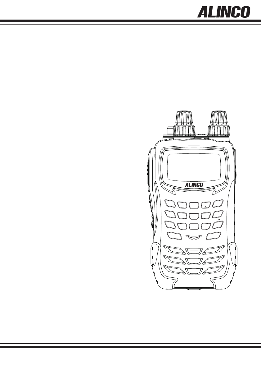
WIDE BAND COMMUNICATION RECEIVER
DJ-X11
Instruction Manual
WILD
1
MODE
GHI
4
NAME
PQ
7
F TUNE
SCAN
GAIN
ABC
2
TONE
JKL
5
PRIO
RS
TUV
8
ATT
DEF
3
LINK
MNO
6
AUDIO
WX
YZ
9
DJ-X11
SET
CLR
SHIFT
0
STEP
ENT
MAIN
SUB
M V
SCOPE
MW
V/P/M
Thank you for purchasing your new Alinco receiver. This instruction manual contains important safety and operating
instructions. Please read this manual carefully before using the product and keep it for future reference
.
ALINCO, INC
Page 2

NOTICE / Compliance Information Statement
NOTICE / Compliance Information Statement
This equipment has been tested and found to comply with the limits for a Class B
digital device, pursuant to part 15 of the FCC Rules.
These limits are designed to provide reasonable protection against harmful
interference in a residential installation.
This equipment generates, uses, and can radiate radio frequency energy and,
if not installed and used in accordance with the instruction manual, may cause
harmful interference to radio communications. However, there is no guarantee
that interference will not occur in a particular moudulation. If this equipment
does cause harmful interference to radio or television reception, which can be
determined by turning the equipment off and on, the user is encouraged to try to
correct the interference by one or more of the following measures:
• Reorient or relocate the receiving antenna.
• Increase the separation between the equipment and receiver.
• Connect the equipment into an outlet on a circuit different from that to
which the receiver is connected.
• Consult the dealer or an experienced radio/TV technician for help.
Tested to Comply
With FCC Standards
FOR HOME OR OFFICE USE
Information in this document is subject to change without notice or obligation. All
brand names and trademarks are the property of their respective owners. Alinco
cannot be liable for pictorial or typographical inaccuracies. Some parts, options
and/or accessories are unavailable in certain areas. Changes or modifi cations not
expressly approved by the party responsible for compliance could void the user’s
authority to operate the equipment.
Wide Band Communication Receiver DJ-X11T
This device complies with Part 15 of the FCC Rules. Operation is subject to the
following two conditions: (1) This device may not cause harmful interference, and
(2) this device must accept any interference received, including interference that
may cause undesired operation.
Manufacturer:
ALINCO, INC.
Yodoyabashi Daibiru Building 13th Floor
4-4-9, Koraibashi, Chuo-ku, Osaka 541-0043, JAPAN
2
Page 3

NOTICE / Compliance Information Statement
Conformity Information
Alinco, Inc. Electronics Division hereby declare on our sole responsibility that the
product(s) listed below comply the essential requirements of the Directive 1999/5/
EC, The council of 3/9/99 on Radio Equipment and Telecommunication Terminal
Equipment and the mutual recognition of their conformity and with the provisions
of Annex, after having performed the required measurements at Notifi ed Bodies
per Standards, and relative certifi cate(s) or document(s) can be reviewed at http://
www.alinco. com/Ce/
DJ-X11E: Wide Band Communication Receiver 0.05 - 1299.99995MHz
DJ-X11EGR: Portable broadcast/hamband Receiver 0.522 - 1.62000MHz
53.75 - 67.7500MHz
87.60 - 107.9000MHz
144.00 - 145.99995MHz
180.75 - 229.7500MHz
430.00 - 439.99995MHz
476.75 - 860.7500MHz
1260.00 - 1299.99995MHz
Function: DJ-X11E DJ-X11EGR
Inversion scramble decoder: Available N/A
DJ-X11E is authorized for use in all EU and EFTA member states except for Greece.
DJ-X11EGR is authorized for use in all EU and EFTA member states.
DJ-X11E : Band-plan setting instruction
In Europe, there are slight differences in frequency allocation country by country.
Therefore the DJ-X11E has been preprogrammed with different VFO and Preset
tables(band-plans) so that it will become handy when you travel. Select one of the
band-plans by pressing the numeric key as instructed below when turning on the unit.
The band plan
Hold 2key while turning on : Pan-Europe
Hold 3key while turning on : UK
Please refer(P. 110)for the details of the band-plans.
Copyright © All rights reserved. No part of this document may be reproduced,
copied, translated or transcribed in any form or by any means without the prior
written permission of Alinco. Inc., Osaka, Japan, English Edition Printed in Japan.
3
Page 4
Warning
Warning
To prevent any hazard during operation of Alinco's radio product, in this manual
and on the product you may find symbols shown below. Please read and
understand the meanings of these symbols before starting to use the product.
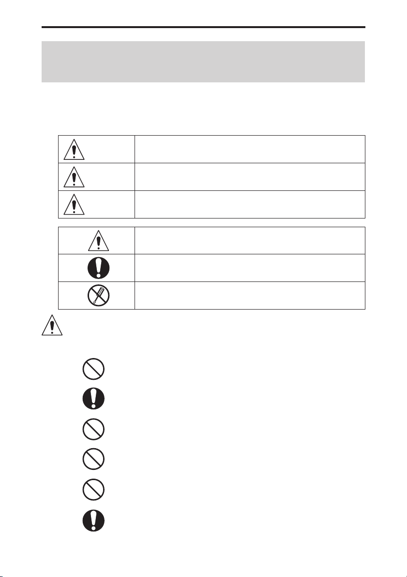
Danger
Alert
Caution
This symbol is intended to alert the user to an immediate danger that
may cause loss of life and property if the user disregards the warning.
This symbol is intended to alert the user to a possible hazard that
may cause loss of life and property if the user disregards the warning.
This symbol is intended to alert the user to a possible hazard that may
cause loss of property or injure the user if the warning is disregarded.
Alert symbol. An explanation is given.
Warning symbol. An explanation is given.
Instruction symbol. An explanation is given.
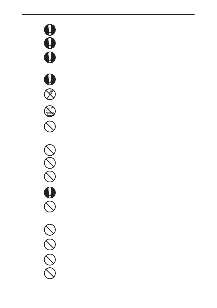
Alert
■
Environment and condition of use
Do not use this product in close proximity to other electronic devices, especially
medical ones. It may cause interference to those devices.
Keep the radio out of the reach of children.
In case a liquid leaks from the product, do not touch it. It may damage your skin.
Rinse with plenty of cold water if the liquid contacted your skin.
Never operate this product in facilities where radio products are prohibited for use
such as aboard aircraft, in airports, in ports, within or near the operating area of
business wireless stations or their relay stations.
Use of this product may be prohibited or illegal outside of your country. Be informed
in advance when you travel.
The manufacturer declines any responsibilities against loss of life and/or property due
to a failure of this product when used to perform important tasks like life-guarding,
surveillance, and rescue.
4
Page 5
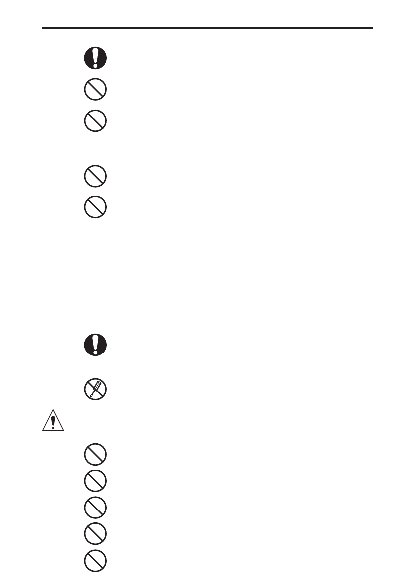
Warning
■
Handling this product
■
About chargers
Risk of explosion if battery is replaced with an incorrect type.
Dispose of, or recycle used batteries according to your local regulations.
The manufacturer declines any responsibilities against loss of life and property due to
a failure of this product when used with or as a part of a device made by third parties.
Use of third party accessory may result in damage to this product. It will void our
warranty for repair.
Be sure to reduce the audio output level to minimum before using an earphone or a
headset. Excessive audio may damage hearing.
Do not open the unit without permission or instruction from the manufacturer.
Unauthorized modification or repair may result in electric shock, fire and/or
malfunction.
Do not operate this product in a wet place such as shower room. It may result in
electric shock, fi re and/or malfunction.
Do not place the product in a container carrying conductive materials, such as water
or metal in close proximity to the product. A short-circuit to the product may result in
electric shock, fi re and/or malfunction.
Do not use adapters other than having the specifi ed voltage. It may result in electric
shock, fi re and/or malfunction.
Do not plug multiple devices using an adapter into a single wall outlet. It may result in
overheating and/or fi re.
Do not handle adapter with a wet hand. It may result in electric shock.
■
About power supply
Securely plug the adapter into the wall outlet. Insecure installation may result in
short-circuit, electronic shock and/or fi re.
Do not use the adapter if the plug or socket contacts are dirty. Overheating and/or
short-circuiting may result in fi re, electric shock and/or damage to the product.
Use only appropriate, reliable power supply of correct voltage and capacity.
Do not connect cables in reverse polarity. It may result in electric shock, fi re and/or
malfunction.
Do not plug multiple devices including the power supply into a single wall outlet. It
may result in overheating and/or fi re.
Do not handle a power supply with a wet hand. It may result in electric shock.
5
Page 6
Warning
■
Cigar-lighter cable
Securely plug the power supply to the wall outlet. Insecure installation may result in
short-circuiting, electronic shock and/or fi re.
Do not plug the power supply into the wall socket if the contacts are dirty.
Short-circuit and/or overheating may result in fi re, electric shock and/or damage to
the product.
Do not modify or remove fuse-assembly from the DC cable. It may result in fire,
electric shock and/or damage to the product.
Do not use the cable at any other than the specifi ed voltage. It may result in electric
shock, fi re and/or malfunction.
Do not handle cigar cable with a wet hand. It may result in electric shock.
■
In case of emergency
In case of the following situation(s), please turn off the product, switch off the source of
power, then remove or unplug the power-cord. Please contact your local dealer of this
product for service and assistance. Do not use the product until the trouble is resolved.
Do not try to troubleshoot the problem by yourself.
• When a strange sound, smoke and/or strange odor comes out of the product.
• When the product is dropped or the case is broken or cracked.
• When a liquid penetrated inside.
• When a power cord (including DC cables, AC cables and adapters) is damaged.
For your safety, turn off then remove all related AC lines to the product and its
accessories from the wall outlet if a thunderstorm is likely.
■
Maintenance
Do not open the unit and its accessories. Please consult with your local dealer of this
product for service and assistance.
Caution
■
Environment and condition of use
6
Do not use the product in proximity to a TV or a radio. It may cause interference or
receive interference.
Do not install in a humid, dusty or insufficiently ventilated place. It may result in
electric shock, fi re and/or malfunction.
Do not install in an unstable or vibrating position. It may result in electric shock, fi re
and/or malfunction when/if the product falls to the ground.
Do not install the product in proximity to a source of heat and humidity such as a
heater or a stove. Avoid placing the unit in direct sunlight.
Be cautious of a dew formation. Please completely dry the product before use when
it happens.
Page 7
■
About receiver
Warning
Be cautious of the whip antenna when carried in your shirt-pocket etc. It may make
contact with your eye and cause injury.
Do not connect devices other than specified ones to the jacks and ports on the
product. It may result in damage to the devices.
Turn off and remove the power source (AC cable, DC cable, battery, cigar cable,
charger adapter etc.) from the product when the product is not in use for extended
period of time or in case of maintenance.
Never pull the cord alone when you unplug AC cable form the wall outlet.
■
About power supply
■
Lightning
Any person is not safe outdoor during thunderstorm and lightning. This condition is getting worse
if somebody keeps a hand-held radio; chances of being hit by lightning are doubled since lightning
may hit a radio antenna as well. At this time, there is no hand-held radio having any kind of
protection against lightning current (which is higher than 10 kA.). Note also that no car provides
adequate protection of its passengers or drivers against lightning as well. Therefore, Alinco will not
take responsibility for any danger associated with using its hand-held radios outdoor or inside the
car during lightning.
■
Notice to California resident users
The Safe Drinking Water and Toxic Enforcement Act of 1986 of the State of California determines
that lead and cadmium are considered carcinogens and reproductive toxicants. The product that
comes with this manual is free from dangerous materials such as lead and cadmium as per RoHS
order of EU.
■
Limited Power Source
Please note that the receiver enclosure only provides mechanical protection of its internal parts; it
will not contain a fi re within the device if the fi re starts under certain fault conditions. Alinco will not
take responsibility for any fi re hazard associated with powering the receiver or charging its batteries
using a power source which does not belong to the limited power sources in the meaning of EN
60950-1. Excluded from possible use with the receiver are most car cigarette lighters and some DC
(AC/DC) power supplies. Make sure that the power supply used with the receiver is a limited power
source.
Use a clean, dry cloth to wipe off dirt and condensation from the surface of the
product. Never use thinner or benzene for cleaning.
Use only reliable power supply of specifi c DC output range and be mindful of the
polarity of the cable and DC-jack.
Always turn off the power supply when connecting or disconnecting the cables.
When using an external antenna, make sure that the antenna ground is not common
with the ground of the power supply.
European users: When a unit is powered from an external DC power source (adapter,
power supply, cigar-plug etc.), make sure that this power supply has approval to the
level of IEC/EN 60950-1.
7
Page 8

Introduction
Introduction
Thank you very much for purchasing this excellent Alinco receiver. Our products
are ranked among the fi nest in the world. This radio has been manufactured with
state of the art technology and it has been tested carefully at our factory. It is
designed to operate to your satisfaction for many years under normal use.
PLEASE READ THIS MANUAL COMPLETELY TO LEARN ALL THE FUNCTIONS
THE PRODUCT OFFERS. WE MADE EVERY ATTEMPT TO WRITE THIS
MANUAL TO BE AS COMPREHENSIVE AND EASY TO UNDERSTAND AS
POSSIBLE. IT IS IMPORTANT TO NOTE THAT SOME OF THE OPERATIONS
MAY BE EXPLAINED IN RELATION TO INFORMATION IN PREVIOUS
CHAPTERS. BY READING JUST ONE PART OF THE MANUAL, YOU RISK NOT
UNDERSTANDING THE COMPLETE EXPLANATION OF THE FUNCTION.
“TV” as used in this manual refers to analog television.
8
Page 9

Table of Contents
Table of Contents
1. Features …………………………………………………………………12
2. Checking the Accessories ……………………………………………… 13
3. Attaching Accessories ……………………………………………………14
3-1 Antenna …………………………………………………………………………………… 14
3-1-1 Attaching the antenna …………………………………………………………… 14
3-1-2 Removing the antenna ………………………………………………………… 14
3-2 Hand Strap ……………………………………………………………………………… 14
3-3 Belt Clip …………………………………………………………………………………… 15
3-3-1 Attaching the belt clip …………………………………………………………… 15
3-3-2 Removing the belt clip …………………………………………………………… 15
3-4 Battery Pack ……………………………………………………………………………… 15
3-4-1 Attaching the battery pack ……………………………………………………… 15
3-4-2 Removing the battery pack …………………………………………………… 16
3-5 Charging the Battery Pack through the DC Jack …………………………………… 17
3-6 Charging the Battery Pack with the Charger ………………………………………… 18
3-7 Preventing the Battery Pack from Short-circuiting …………………………………… 18
3-8 Dry Battery Case ………………………………………………………………………… 19
3-9 Battery Level Icons ……………………………………………………………………… 20
4. Part Names and Operation ……………………………………………21
4-1 Part Names and Functions of the Receiver ………………………………………… 21
4-1-1 Top and front panels …………………………………………………………… 21
4-1-2 Side panels ……………………………………………………………………… 22
4-1-3 Key operation …………………………………………………………………… 23
4-2 LCD Display ……………………………………………………………………………… 24
5. Basic Operation …………………………………………………………25
5-1 Turning the Power ON ………………………………………………………………… 25
5-2 Tuning the Frequency …………………………………………………………………… 25
5-3 Adjusting the Volume Level …………………………………………………………… 25
5-4 Adjusting Squelch Level ………………………………………………………………… 26
5-4-1 Operating procedure …………………………………………………………… 26
5-5 Monitor function ………………………………………………………………………… 27
5-6 Mute Function …………………………………………………………………………… 27
5-7 Selecting the Band to Operate ………………………………………………………… 28
5-7-1 Mono-band operation …………………………………………………………… 28
6. Operating Modes …………………………………………………………29
6-1 Setting frequencies in VFO mode ……………………………………………………… 30
6-2 Setting the Channel Step Frequency ………………………………………………… 30
6-3 1 MHz UP/DOWN Operation …………………………………………………………… 30
6-4 Setting Frequencies through Direct Input …………………………………………… 31
6-5 Setting frequencies in Preset mode …………………………………………………… 31
6-6 Receiving Operation …………………………………………………………………… 32
7. Memory Mode …………………………………………………………… 34
7-1 Memory Types and Usage ……………………………………………………………… 34
7-2 Programming a Memory Channel ……………………………………………………… 35
7-3 Calling Up a Memory Channel ………………………………………………………… 38
7-4 Deleting a Memory Channel …………………………………………………………… 38
7-5 Editing a Memory Channel……………………………………………………………… 39
1
2
3
4
5
6
7
8
9
10
11
12
13
14
15
16
17
9
Page 10

10
Table of Contents
7-6 Quick Memory …………………………………………………………………………… 40
7-6-1 Programming a memory channel to the quick memory ……………………… 40
7-6-2 Calling up a memory channel from the quick memory ……………………… 40
7-7 Memory Skip Function ………………………………………………………………… 40
7-8 Memory Naming Function ……………………………………………………………… 41
8. Functions Assigned to the Key Pad ……………………………………48
8-1 Shortcut Function ……………………………………………………………………… 48
8-2 Receiving Sensitivity (RF Gain) Adjustment and Attenuator Function …………… 48
8-3 Switching the Modulation Mode ……………………………………………………… 50
8-4 Setting the Tone Squelch/DCS ………………………………………………………… 51
8-4-1 Tone Squelch function …………………………………………………………… 51
8-4-2 DCS function …………………………………………………………………… 53
8-5 Bank Link Setting Function …………………………………………………………… 54
8-6 Priority Monitoring Function …………………………………………………………… 55
8-7 Received Sound Quality Adjustment Function ……………………………………… 56
8-8 Frequency Shift Function ……………………………………………………………… 57
8-8-1 Setting the Frequency Shift function …………………………………………… 57
8-8-2 Using the function ……………………………………………………………… 57
8-9 Changing the Channel Step …………………………………………………………… 58
8-10 Channel Scope Function ……………………………………………………………… 59
8-10-1 VFO Channel Scope …………………………………………………………… 60
8-10-2 Memory Channel Scope ……………………………………………………… 61
8-11 Copying the Memory Channel Data into VFO Mode ……………………………… 62
8-12 F Tuning Function ……………………………………………………………………… 62
9. Useful Functions …………………………………………………………63
9-1 Key-lock Function ……………………………………………………………………… 63
9-1-1 Key-lock procedure ……………………………………………………………… 63
9-1-2 Operations available while the Key-lock is active …………………………… 63
9-2 Scanning Function ……………………………………………………………………… 64
9-3 VFO Scan ………………………………………………………………………………… 64
9-4 Preset Scan ……………………………………………………………………………… 65
9-5 Memory scan …………………………………………………………………………… 65
9-6 Programmed Scan ……………………………………………………………………… 66
9-7 Tone Scan ………………………………………………………………………………… 66
9-8 DCS Scan ………………………………………………………………………………… 67
9-9 Sweep Scan ……………………………………………………………………………… 68
9-10 Bug Detector Function ………………………………………………………………… 69
9-10-1 Operating procedure in Silent mode ………………………………………… 69
9-10-2 Operating procedure in Sound mode ………………………………………… 70
9-10-3 Mode coupling setting of the Bug Detector function ……………………… 71
9-10-4 Sensitivity setting of the Bug Detector function …………………………… 72
10. Set Mode Confi gurations ………………………………………………73
10-1 Receiver Setting ……………………………………………………………………… 74
10-1-1 Bar antenna setting …………………………………………………………… 74
10-1-2 Earphone antenna setting …………………………………………………… 75
10-1-3 Preset mode setting …………………………………………………………… 75
10-1-4 CW setting ……………………………………………………………………… 76
10-1-5 Detected signal output function ……………………………………………… 76
10-1-6 F Tuning function operation setting ………………………………………… 77
10-1-7 IQ signal output function ……………………………………………………… 77
10-2 Screen Display Setting ………………………………………………………………… 78
10-2-1 Language setting ……………………………………………………………… 78
10-2-2 Illumination setting ……………………………………………………………… 78
10-2-3 Contrast setting ………………………………………………………………… 79
10-2-4 Font size setting ………………………………………………………………… 79
10-2-5 Font style setting ……………………………………………………………… 79
10-2-6 Welcome screen setting ……………………………………………………… 80
Page 11

Table of Contents
10-3 Power and Battery Setting …………………………………………………………… 81
10-3-1 Auto power off setting ………………………………………………………… 81
10-3-2 Battery setting ………………………………………………………………… 82
10-3-3 Battery save function setting ………………………………………………… 82
10-4 Key Assignment Setting ……………………………………………………………… 83
10-4-1 Key-lock mode setting ………………………………………………………… 83
10-4-2 Set mode exit time setting …………………………………………………… 84
10-4-3 Band transition setting ………………………………………………………… 84
10-4-4 Right/left dial function setting ………………………………………………… 85
10-4-5 Upper/lower dial function setting ……………………………………………… 85
10-4-6 Assigning a function to the WILD key ………………………………………… 86
10-4-7 Assigning a function to the MONI key ……………………………………… 86
10-4-8 Setting the band operated with the MONI key ……………………………… 86
10-4-9 MONI key activation setting …………………………………………………… 87
10-4-10 MONI key setting ……………………………………………………………… 87
10-4-11 Remote COM port setting …………………………………………………… 88
10-5 Scan Setting …………………………………………………………………………… 88
10-5-1 Scan mode setting ……………………………………………………………… 88
10-5-2 Priority Monitoring interval setting …………………………………………… 89
10-5-3 Priority Monitoring duration setting …………………………………………… 90
10-5-4 Skip scan operation setting …………………………………………………… 90
10-5-5 Scan speed setting …………………………………………………………… 91
10-6 Memory Setting ………………………………………………………………………… 91
10-6-1 Write-protect (memory protection) function setting ………………………… 91
10-6-2 Memory name display setting ………………………………………………… 92
10-7 Sound Setting ………………………………………………………………………… 92
10-7-1 Beep setting …………………………………………………………………… 92
10-7-2 Bell function setting …………………………………………………………… 93
10-7-3 Voice Guidance function setting ……………………………………………… 94
10-8 Remote Controller Setting …………………………………………………………… 95
11. Channel Display Mode …………………………………………………96
12. Cable-clone and PC Connection Functions …………………………97
12-1 PC Connection and Connection Ports ……………………………………………… 97
12-2 Cable-Clone Receiving Data ………………………………………………………… 99
12-3 Cable-Clone Transferring Data ……………………………………………………… 100
13. Reset Function ……………………………………………………… 101
13-1 Reset …………………………………………………………………………………… 101
14. Using the Optional Remote Controller …………………………… 102
14-1 Using the Remote Controller ………………………………………………………… 102
14-1-1 Top/Bottom/Front panels ………………………………………………………102
14-1-2 Side panel ……………………………………………………………………… 102
14-2 Connecting the Remote Controller …………………………………………………… 103
14-3 Remote Controller Functions …………………………………………………………103
15. Maintenance and Reference ……………………………………… 104
15-1 Troubleshooting ………………………………………………………………………… 104
15-2 Optional Accessories List ………………………………………………………………105
15-3 After-sales Service …………………………………………………………………… 106
16. Index ………………………………………………………………… 107
17. Specifi cations ………………………………………………………… 109
17-1 Specifi cations …………………………………………………………………………… 109
17-2 The Band-plans ………………………………………………………………………… 110
17-2-1 Switching the main band ……………………………………………………… 110
17-2-2 Switching the sub band ……………………………………………………… 112
1
2
3
4
5
6
7
8
9
10
11
12
13
14
15
16
17
11
Page 12

1
1. Features
1.
The DJ-X11 is a multifunctional receiver which receives a wide range of radio
signals from low-frequency (LF) signals to ultra-high-frequency (UHF) signals.
It provides the following features:
Features
Receives a wide range of frequencies - between 0.05 and 1299.99995
1
MHz - including aviation radio and business communication frequencies.
Dual-frequency simultaneous reception for receiving signals with main and
2
sub bands simultaneously. (The frequencies which can be received with
the sub band are limited.)
Various reception modes supported including SSB/CW as well as FM/
3
WFM/AM. The DJ-X11 can receive not only AM/FM radio signals and
analog TV sounds, but also SSB mode signals which are used for amateur
band Morse code and ship/aviation radios.
F Tuning function which quickly tunes to the very strong RF signal and
4
receives it, if such signal may exist.
Built-in bar-antenna receives AM radio , eliminating the need to attach an
5
external antenna.
Earphone cord can be used as an antenna to receive FM broadcast and
6
other stronger signals without using an external antenna.
Automatic input switching. By connecting the optional remote controller to
7
the earphone jack and connecting an MP3 player or other portable audio
device to the controller, you can listen to music under normal conditions
and hear receiver messages when the DJ-X11 receives any signals.
Bug Detector function in two modes. This function notifies you of the
8
possible presence of a bugging device (wireless microphone) with a
display, an alarm and a voice announcement.
Clone function for copying settings and various data between the receiver
9
units. It is also possible to connect the receiver to a personal computer to
edit settings and data.
Tone Squelch and DCS, cut off shrill and rattling noises so that only the
10
target sound can be heard.
Scan speed is selectable from 3 levels. Select a fast scan speed to detect
11
strong signals, and select a slower scan speed to detect weak signals.
Voice Guidance function which announces the result of key operations or
12
the Bug Detector function in English.
12
Page 13

2. Checking the Accessories
2.
The package of the DJ-X11 contains the following items. Check that all items are
included in your package before using the receiver.
Checking the Accessories
Instruction Manual (this manual)
Warranty certifi cate (T/K versions only)
Dry battery case (EDH-36)
Lithium ion battery pack (EBP-74 3.7 V, 1800 mAh)
AC adapter (EDC-139; T/K EDC-140; E/EGR)
Charger stand (EDC-174)
Whip antenna (SMA/EA-154)
Belt clip (EBC-23)
Hand strap
Standard accessory may vary depending on the model you have purchased.
Please consult with your Alinco dealer of the details before purchase.
2
13
Page 14
3. Attaching Accessories
3
3.
Attaching Accessories
3-1 Antenna
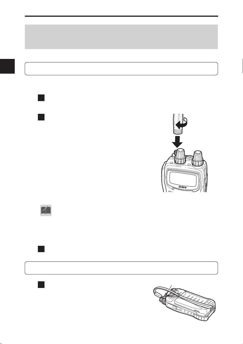
3-1-1 Attaching the antenna
1
Hold the antenna at its base and rotate it clockwise (to
the right).
2
When you cannot rotate the
antenna further, confirm that
it is securely attached to the
receiver.
• To avoid breakage, the supplied antenna is made of a more fl exible
material than that of typical antennae.
• This connector is also used for the connection of an external antenna.
MEMO
14
3-1-2 Removing the antenna
1
Rotate the antenna counterclockwise (to the left).
3-2 Hand Strap
1
Attach the hand strap to the
hole on the rear of the receiver
as shown in the fi gure.
Hand strap
Page 15
3-3 Belt Clip
3. Attaching Accessories
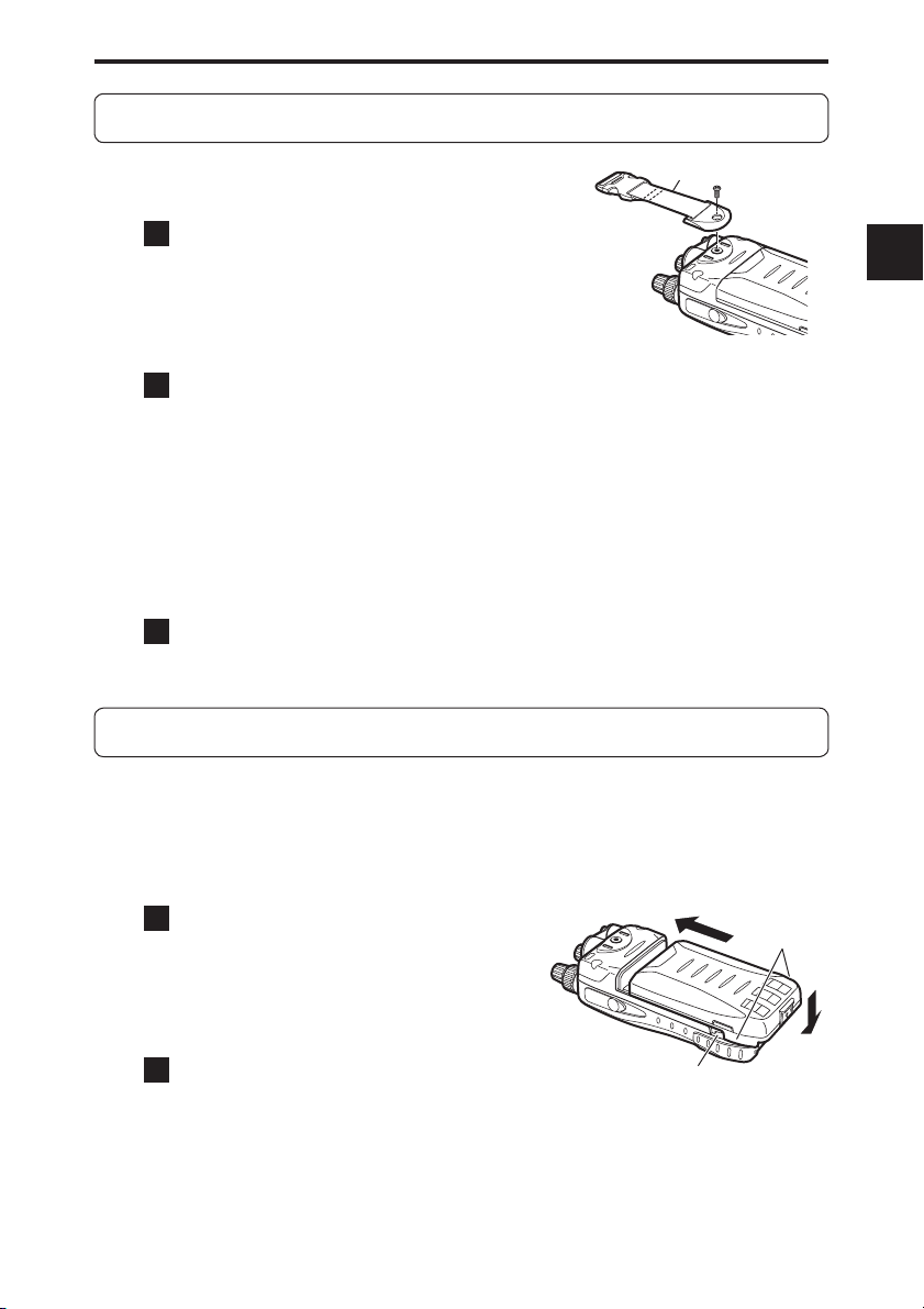
3-3-1 Attaching the belt clip
1
Align the belt clip with the groove
Belt clip
at the rear of the receiver to
secure it, insert the screw into the
hole and rotate it clockwise (to
the right).
2
Check that the belt clip is securely
attached to the receiver.
* The screw may become loose during use. Check the tightness from
time to time.
* The belt clip can be adjusted so that it can be used for a belt of
approximately 8 cm width at maximum.
3-3-2 Removing the belt clip
1
Rotate the screw counterclockwise (to the left) and
remove the belt clip.
3-4 Battery Pack
For the procedure for charging the lithium ion battery pack (EBP-74), refer to
“Charging the Battery Pack with the Charger” (P. 18) and “Charging the Battery
Pack through the DC Jack” (P. 17).
3
3-4-1 Attaching the battery pack
1
Align the hooks of the battery
pack with the grooves of
the receiver and push in the
battery pack in the direction of
arrow (1).
2
Slide the lock lever at the
bottom of the battery pack in
the direction of arrow (2).
(1)
Hooks
(2)
Groove
15
Page 16

3. Attaching Accessories
3-4-2 Removing the battery pack
3
1
Slide the lock lever at the
bottom of the battery pack in
the direction of arrow (1) and
remove the battery pack (2).
• The battery pack is not fully charged when shipped. You need to
CAUTION
charge it after purchase before use.
• The battery pack must be charged within the temperature range of 0 to
40°C.
• Do not modify or dismantle the battery pack and do not throw it into fi re
or water. These actions are dangerous.
• Do not short-circuit the battery pack terminals. This may damage the
equipment, or may cause burns by the heat generated from the battery.
Do not charge the battery pack for an unnecessarily long time (overcharging). This may deteriorate battery performance.
• The battery pack should be stored in a dry place where the temperature range is between -10°C and +45°C. Storing the battery pack in
locations with high humidity or temperatures outside the proper range
may cause the battery solution to leak or the metal sections to rust.
• The battery pack is a consumable article. When the battery pack becomes exhausted extremely quickly even when it has been charged
for the specifi ed time, it may have reached the end of its life. In such a
case, replace the battery pack with a new one.
• The battery pack is a recyclable resource. Do not dispose the battery
pack but take it to a battery recycling center in your area. The battery
pack is dedicated for use in Alinco products. It can be charged only using the applicable genuine charger or conforming receiver. Charging
it with commercially-available or third-party chargers or adapters may
cause a breakage or accident. Clean the electrodes of the battery pack
and charger with a dry cotton swab from time to time.
• Even if you do not use the battery pack for a long time, charge it at
least once every three months to prevent deterioration.
• The supplied battery pack is dedicated for use in the DJ-X11. Charging
it with chargers or adapters other than specifi ed models may cause a
breakage or accident.
(2)
(1)
16
Page 17
3. Attaching Accessories
3-5
Charging the Battery Pack through the DC Jack
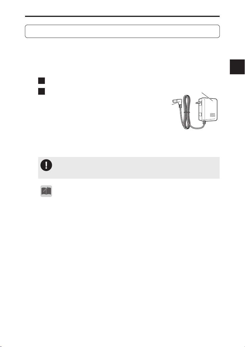
The supplied lithium ion battery pack can be charged through the DJ-X11 by using the supplied AC adapter and a DC power supply (6 VDC, 1 A or more: IEC/
EN60950 standard). It takes about six hours to fully charge the battery pack
from a state of complete discharge.
1
Attach the battery pack by referring to “Battery Pack” (P. 15).
2
Connect the plug of the AC
AC adapter*
adapter into the DC jack of the
DJ-X11 and plug the AC adapter
into a wall outlet.
* Your AC adapter may have a different
shape from the AC adapter shown in
the fi gure.
For the battery level indication during charging, refer to “Battery Level Icons” (P. 20).
• When the receiver is used with the supplied AC adapter connected, the
CAUTION
reception may be affected by noise; however, this is not a malfunction.
AC adapter
plug
3
• Also read the precautions supplied with the optional accessories care-
MEMO
fully to ensure proper use and safety.
• If the voltage of the wall outlet is not stable, the battery pack may not
be charged properly.
17
Page 18
3. Attaching Accessories
3-6 Charging the Battery Pack with the Charger
3
3-7
Using the supplied charger completes charging in about four hours from a state
of complete discharge.
1
Connect the plug of the AC adapter to the charger.
2
Plug the AC adapter into a wall
outlet and place the DJ-X11 on
the charger.
During charging, the red lamp of the
charger illuminates.
When the charging is complete,the lamp
goes off.
EDC-174 doesn't charge when EBP-74 is
fully charged and thered lamp stays off.
• If charging fails with the battery pack attached to the receiver, try
MEMO
charging the battery pack alone and check the operation.
• The battery pack can also be charged by using the optional PC connection cable (ERW-8). (About eight hours)
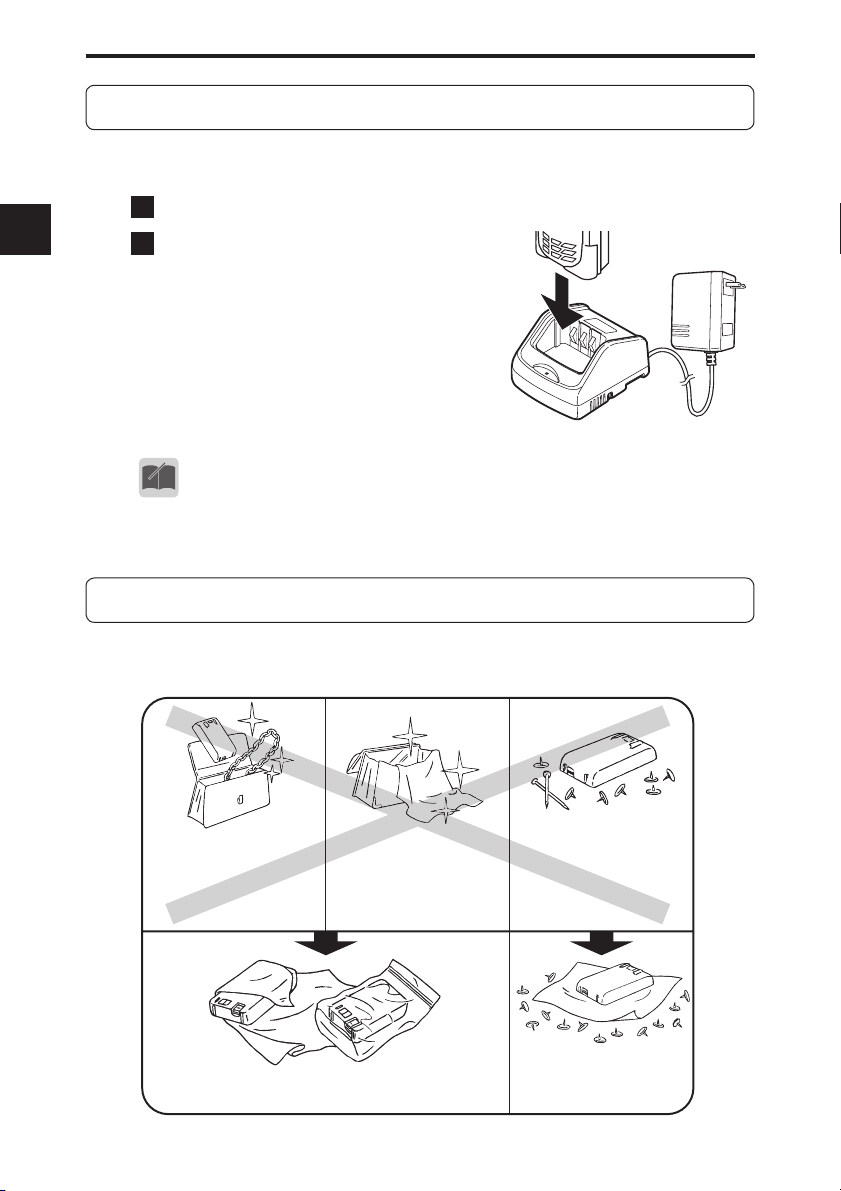
Preventing the Battery Pack from Short-circuiting
18
Take extreme caution when carrying the battery pack. A current surge caused
by short-circuiting may cause a fi re.
DON’T carry with metals
of any type, e.g. chains.
Do enclose inside a non-conductive enclosure. (bags
or handkerchief made only of non-conductive material)
DON’T carry the battery
pack inside bags made of
conductive materials.
DON’T place in the
proximity of metals or
conductives, e.g. nails,
chains.
Do protect by spreading a
non-conductive sheet on
a flat surface.
Page 19
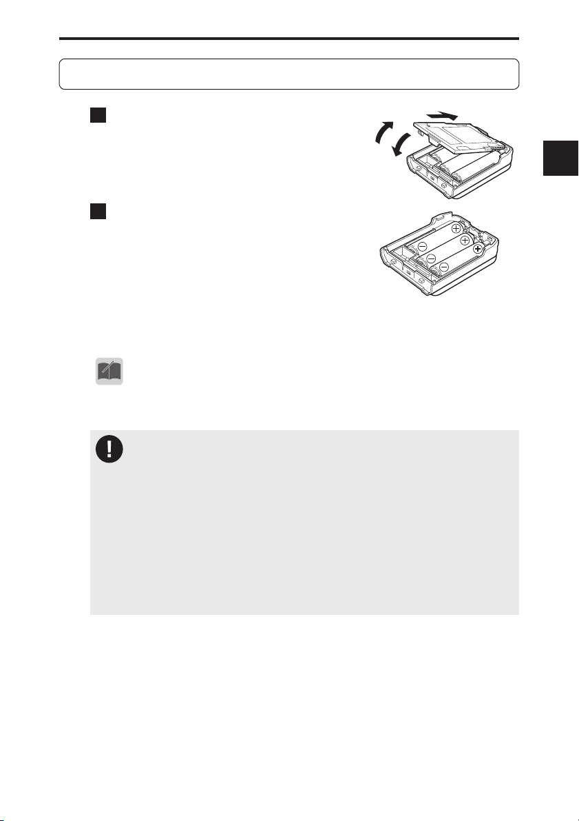
3-8 Dry Battery Case
3. Attaching Accessories
1
Push up tab (1) and remove the
lid.
(1)
(3)
(2)
3
2
Set three AA dry batteries in
the case and close the lid in the
order of 2 and 3. Check that the
lid is closed securely. You must
use alkaline dry batteries. Manganese dry batteries cannot be
used.
• To use dry batteries, read the instructions in “Battery setting” (P. 82).
MEMO
Precautions on using the dry battery case
• Be careful of the orientation of the batteries. Inserting them in the in-
CAUTION
correct orientation may cause electrical leakage, fi re, or explosion.
• Use new dry batteries of the same type and manufacturer.
• When replacing the batteries, replace all batteries with new ones.
• Rechargeable batteries must not be used. Alinco assumes no responsibility for any property damage or physical injuries resulting from the
use of rechargeable batteries.
• Clean the electrodes which make contact with the dry batteries with a
clean, dry cloth or cotton swab from time to time.
• Using batteries of the wrong type may cause an explosion.
19
Page 20
3. Attaching Accessories
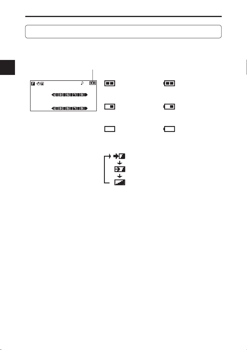
3-9 Battery Level Icons
3
The battery icon displayed on the LCD of the DJ-X11 indicates the remaining
battery power. When the battery icon indicates empty, charge the battery pack
or replace the dry batteries with new ones.
Battery icon
ATH
VFO
145.000
BUSY
MR
433.000
001
000
BUSY
-
BSDCS
Remaining battery
FM
power is sufficient.
FM
Remaining battery
power is decreasing.
Remaining battery
power is low.
Remaining dry battery
power is sufficient.
Remaining dry battery
power is decreasing.
Remaining dry battery
power is low.
Battery pack is being
charged.
When the receiver is turned OFF, “Charging” is displayed on the LCD. When the
charging is complete, “Charge completed” is displayed.
20
Page 21
4. Part Names and Operation
4.
Part Names and Operation
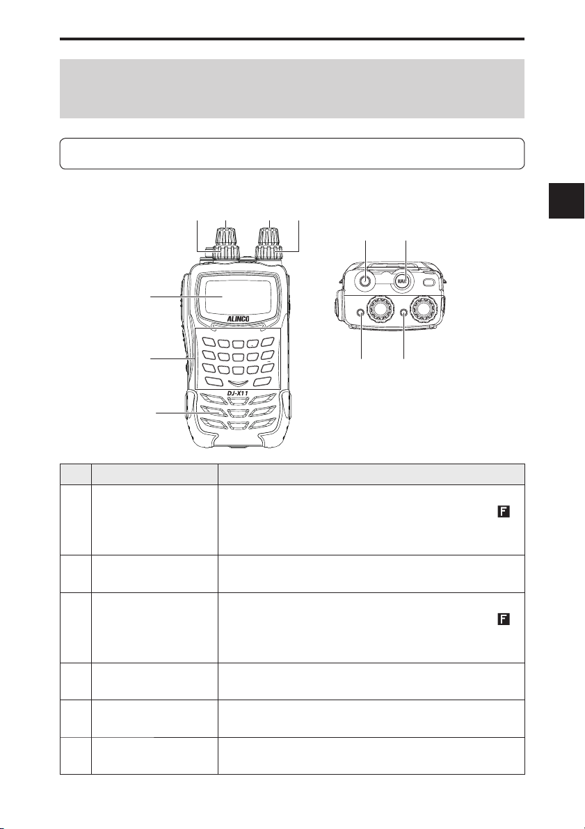
4-1 Part Names and Functions of the Receiver
4-1-1 Top and front panels
(1)(2) (4)(3)
(8)
(7)
(5)
WILD
GAIN
SET
ATT
1
2
MODE
TONE
GHI
4
(6)
NAME
PQ
7
RS
F TUNE
SCAN
5
PRIO
8
(11)
No. Name Function
(1) Upper main dial
Rotate the dial to change the frequency/memory channel or
to set items for the main band. Pressing this dial while
displayed switches the receiver to the mode coupling setting
of the Bug Detector function.
(2) Lower main dial
Rotate the dial to change audio volume or set items for the
main band.
(3) Upper sub dial
Rotate the dial to change the frequency/memory channel
or set items for the sub band. Pressing this dial while
displayed switches the receiver to the sensitivity setting of
the Bug Detector function.
(4) Lower sub dial Rotate the dial to change audio volume or set items
for the sub band.
(5) LCD The status of the receiver is displayed. Refer to "LCD
Display" for details.
(6) Key pad Use these keys for direct frequency input or various
settings.
MAIN
ABC
CLR
DEF
3
SHIFT
LINK
SUB
JKL
MNO
0
6
M V
STEP
AUDIO
WX
SCOPE
TUV
ENT
YZ
9
MW
V/P/M
(9) (10)
4
is
is
21
Page 22
4. Part Names and Operation
No. Name Function
(7) Antenna connector
(SMA)
(8) Earphone jack Used to connect an external earphone.
(9) Main RX lamp This lamp illuminates in green while the main band
4
(10) Sub RX lamp This lamp illuminates in green while the sub band
(11) Speaker A low-profi le, built-in speaker is provided.
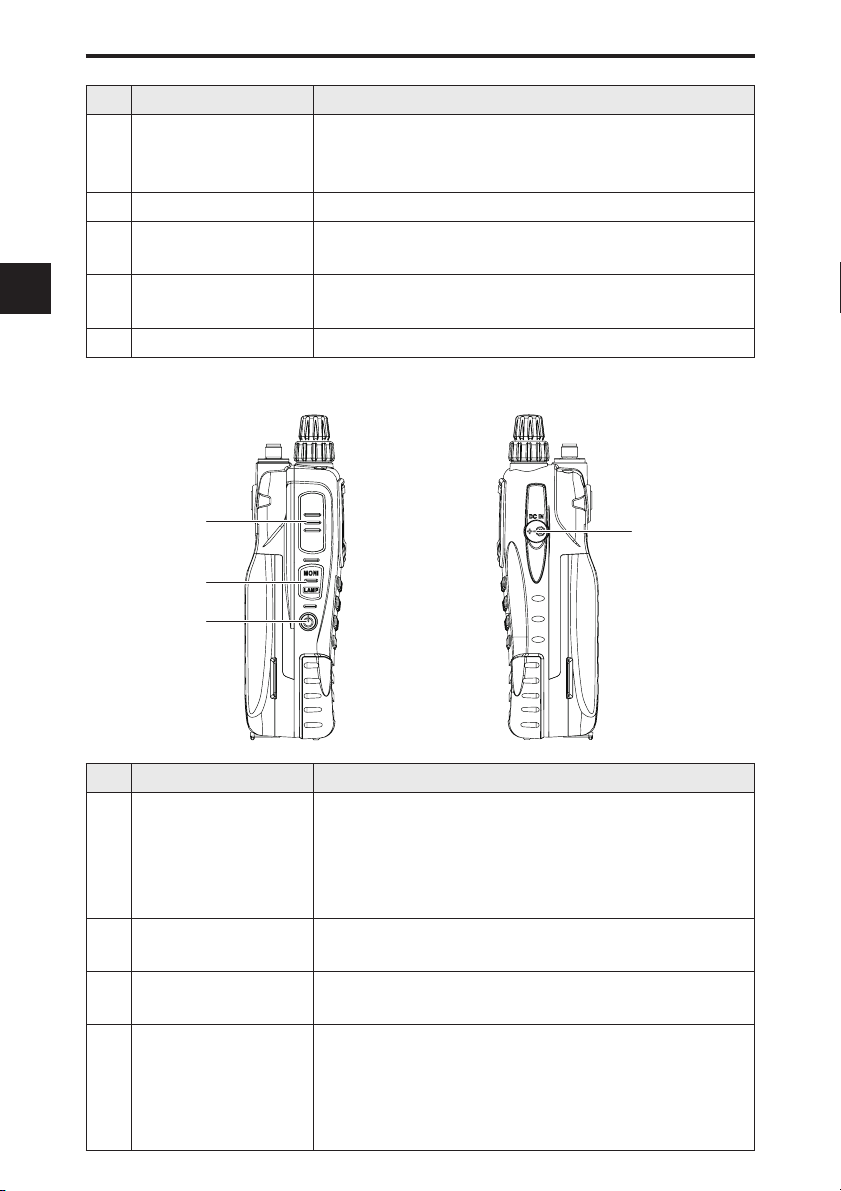
4-1-2 Side panels
Attach the supplied antenna securely. To use other
antennae, select an antenna which has been tuned to
operate within the specifi ed operating frequency range.
squelch is open.
squelch is open.
22
(12)
(13)
(14)
No. Name Function
(12) FUNC key Use this key in combination with other keys to use
various functions. Rotating the upper main/sub dial
while holding down this key changes the frequency
by 1 MHz. Holding down this key (approx. 1 second)
activates/deactivates the Quick Key-lock function.
(13) MONI key
(LAMP key)
(14) POWER key Hold down this key (approx. 1 second) to turn ON/
(15) DC jack This is an external power supply connection terminal.
Press this key to open the squelch and hear the
received sound.
OFF the receiver.
Connect the supplied AC adapter, or connect the
optional cigarette lighter cable to use the receiver in a
car. To use a stabilized power supply, be sure to use a
power supply of 6.0 VDC and 1 A or higher.
(15)
Page 23
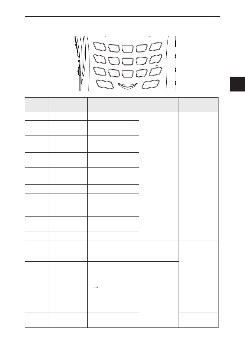
4-1-3 Key operation
WILD
1
MODE
GHI
4
NAME
PQ
7
RS
F TUNE
SCAN
GAIN
ABC
2
TONE
JKL
5
PRIO
TUV
8
ATT
DEF
3
LINK
MNO
6
AUDIO
WX
YZ
9
SET
CLR
SHIFT
0
STEP
ENT
MW
V/P/M
4. Part Names and Operation
MAIN
SUB
M V
SCOPE
4
Name Function After the FUNC Key
is Pressed
1
Enter 1. WILD key Program/cancel
2 Enter 2. Adjust the receiving
sensitivity.
3 Enter 3. Set the Attenuator.
4 Enter 4.
Switch the modulation mode.
Hold Down the Key
(Approx. 1 Second)
Hold Down the Key
and Operate the Dial
the quick
memory (in
Memory mode).
5 Enter 5. Set the Tone
Squelch/DCS
6 Enter 6. Set the bank link.
7 Enter 7.
8 Enter 8.
9 Enter 9.
Set the memory name.
Priority Monitoring function
Received Sound Quality
-
Adjustment function
0 Enter 0. (rev)
. Enter a decimal
point. (CLR)
ENT
MAIN
Determine the entry.
Switch bands/
banks.
Frequency Shift function
Call up Set mode.
Channel step
Edit the memory
channel.
Switch the main
band between
-
Switch bands/
banks.
dual-/mono-band.
SUB
Switch bands/
banks.
Switch the sub
-
band between
dual-/mono-band.
SCOPE Channel Scope
function
V/P/M
Switch operation
modes.
M V function
Program/clear the
memory channel.
-
-
SCAN SCAN key F Tuning function Select the scan
mode.
23
Page 24
4. Part Names and Operation
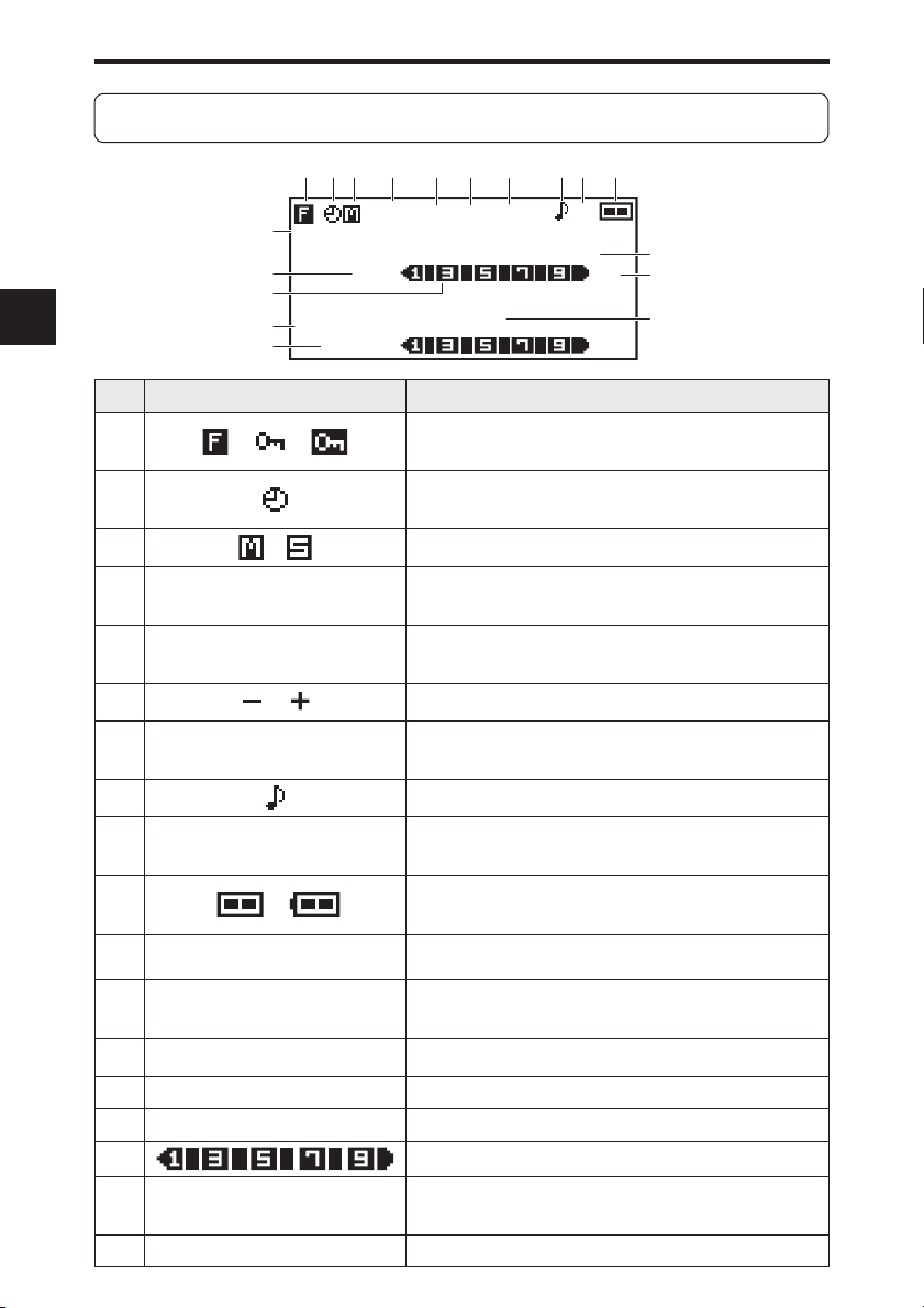
4-2 LCD Display
4
24
(1) (2) (3) (4) (6)(5)
(18)
VFO
(17)
(16)
MR
(15)
001
(14)
000
No. Indication Function
(1)
(2)
(3)
(4)
(5)
(6)
(7)
(8)
(9)
(10)
(11)
(12)
(13)
(14)
(15)
(16)
(17)
(18)
/ /
/
/
ATL
ATH
D
/
/SQ/
TSQ
BS
/
145.000
FM
433.000
0
001
BUSY
/
VFO
MUTE
ATH
145.000
BUSY
433.000
BUSY
DCS
-
Appears when the [FUNC] key is pressed or
when the Key-lock is activated (P. 63).
Appears while the Auto Power OFF function is
ON (P. 81).
Indicates the band to be operated. (P. 28)
Appears while the Attenuator function is ON (P.
48, P. 49).
Appears while the Detection Signal Output
function is ON (P. 76).
Indicates the frequency shift direction. (P. 57)
Appears while the Tone Squelch/DCS is ON
(P. 51 - P. 53).
Appears while the Bell function is ON (P. 93).
Appears while the Battery Save function is ON
(P. 82, P. 83).
Indicates the remaining power of the battery pack/
dry batteries. (P. 82)
Indicates the frequency of the main band.
Indicates the modulation mode (FM, Wide FM,
AM, USB, LSB, CW). (P. 50)
Indicates the frequency of the sub band.
Indicates the memory bank No. (P. 34 - )
Indicates the memory channel No. (P. 34 - )
Indicates the reception level.
Appears while the squelch is open or while the
Mute function is ON (P. 26, P. 27, P. 86, P. 87).
Indicates the operation mode status. (P. 29 - P. 33)
(7)
(8)(9) (10)
BSDCSD
FM
FM
(11)
(12)
(13)
Page 25
5. Basic Operation
5.
Basic Operation
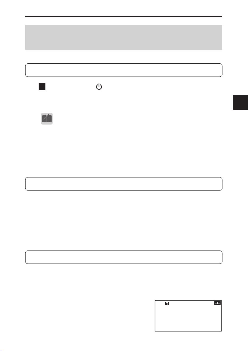
5-1 Turning the Power ON
1
Hold down the [POWER] key (approx. one second) to
turn the power ON.
Hold down the key again to turn the power OFF.
•
Due to utilize the capacity of the battery in full to maximize the operat-
MEMO
ing time, a special tune has been performed to the circuit of the DJ-X11.
For this reason, you may encounter an event that the unit can’t be
turned on after the battery pack is completely discharged and turned off
by itself. In this case, remove any power source (the battery pack, dry
cell case and external DC cable/adapter) from the unit, wait for 5 seconds or so, then supply one of correct DC power sources again to turn
on. At this status, even an empty battery pack should work with an AC
adapter.
5-2 Tuning the Frequency
For the procedure to select the band to tune, refer to (P. 28).
● Tuning the frequency for the main band
Rotate the upper main dial.
● Tuning the frequency for the sub band
Rotate the upper sub dial.
Rotating the dial clockwise sets the frequency higher; rotating the dial
counterclockwise sets the frequency lower.
5
5-3 Adjusting the Volume Level
Volume can be adjusted within the range of 31 levels from 0 to 30.
The default is set to 10.
When you hold down the [MONI] key, you will hear a hissing sound. Use this
sound as a guide for adjustment.
● Adjusting the volume of the main band
Rotate the lower main dial.
● Adjusting the volume of the sub band
Rotate the lower sub dial.
Rotating the dial clockwise increases the
volume; rotating the dial counterclockwise decreases the volume.
VFO
145.000
Main volume 10
BS
FM
25
Page 26
5. Basic Operation
• When using earphones, be careful that the volume is not set too loud.
CAUTION
When nothing is heard
• When the squelch is closed or the Mute function is activated, you will
MEMO
Start from a low level and gradually increase it while actually listening
to the sound.
hear nothing even if you increase the volume level. For details, refer
to the following sections “Adjusting Squelch Level” (P. 26) and “Mute
Function” (P. 27).
5
5-4 Adjusting Squelch Level
● What is “squelch”?
The Squelch function activates the speaker only when signals at a
specified level or higher are received. This makes it easier to catch
target signals by eliminating the noise which occurs when no signals are
received. When the squelch level is increased, the receiver can receive
strong signals, but cannot receive weak signals.
“To open the squelch” means to deactivate the squelch. “To close the
squelch” means the opposite. The strength of the signals required to
open the squelch is determined by the squelch setting level. This level is
adjustable because it varies in some degree depending on the location of
signal reception and receiving frequency.
The squelch can be adjusted within the range of 10 levels (0 to 9).
5-4-1 Operating procedure
● Adjusting the squelch for the main band
Press the main dial once and rotate it.
● Adjusting the squelch for the sub band
Press the sub dial once and rotate it.
VFO
145.000
BS
Main squelch 3
BS
Sub squelch 3
VFO
433.000
FM
FM
FM
FM
26
Rotating the dial clockwise sets the squelch level higher; rotating the dial
counterclockwise sets the squelch level lower.
• To keep the squelch constantly open, set the squelch level to 0.
• While the squelch is open, scanning is disabled except for the periodic
scan. To enable scanning, adjust the squelch level until you cannot hear
any noise.
Page 27
5. Basic Operation
5-5 Monitor function
The Monitor function forces the squelch to open. When receiving signals are
relatively weak or are often interrupted, it opens the squelch temporarily, regardless of the current squelch level. This function is activated when the “Monitor
key operation setting” (P. 87) is set to the Monitor function.
There are two options for the Monitor function: PUSH and HOLD. When the
[MONI] key is pressed, both options open the squelch and the “BUSY” appears
on the LCD.
• For the procedure to switch between PUSH and HOLD, refer to “Monitor key
operation setting” (P. 87)
• When PUSH is selected, the squelch opens only while the [MONI] key is held
down. When the [MONI] key is released, the squelch returns to the original
level.
• When HOLD is selected, the squelch remains open once the [MONI] key is
pressed. When the [MONI] key is pressed again, the squelch returns to the
original level.
• When the Monitor function is used, the Tone Squelch and DCS func-
MEMO
tions is also disabled temporarily.
• If you cannot receive any signals and suspect a malfunction, use this
function to check if the receiver can receive signals properly.
5-6 Mute Function
The Mute function silences sounds. It cuts off audio outputs even when signals
are received. This function is activated when the “MONI key setting” (P. 87) is
set to the Mute function. This function is useful when you want to silence the
sound with one key touch without adjusting the volume.
There are two options for activating the Mute function: PUSH and HOLD. When
the [MONI] key is pressed, either option activates the Mute function and “MUTE”
illuminates on the LCD.
5
• Only one of the Monitor function and Mute function can be selected at
a time.
MEMO
27
Page 28
5
5. Basic Operation
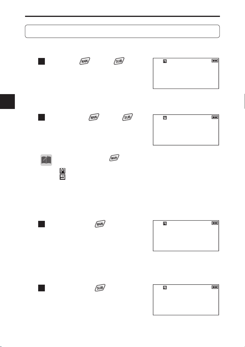
5-7 Selecting the Band to Operate
Select either the main band or sub band to operate.
Refer to (P. 33) for the range of the receivable frequencies for each band.
Press the key or key to
1
select the band to operate.
When the dual-band display is selected,
the frequency of the selected band is
displayed in larger letters. When the
mono-band display is selected, only
the frequency of the selected band is
displayed.
Pressing the key or key
2
again changes the band.
VFO
VFO
VFO
VFO
433.000
145.000
145.000
433.000
BS
FM
FM
BS
FM
FM
• By holding down the
MEMO
change the band quickly.
•
indicates that the main band is currently selected for operation;
indicates that the sub band is currently selected for operation.
key and rotating the upper dial, you can
5-7-1 Mono-band operation
● Using the main band with mono-band operation
Hold down the key (approx.
1
one second).
The main band is displayed with the
mono-band display. To return to the dualband display, repeat the same operation
again.
● Using the sub band with mono-band operation
Hold down the key (approx.
1
one second).
The sub band is displayed with the monoband display.
To return to the dual-band display, repeat
the same operation again.
VFO
VFO
145.000
433.000
BS
FM
BS
FM
28
Page 29
Operating Modes
6.
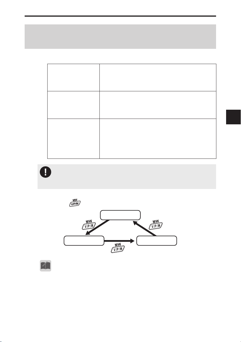
The DJ-X11 has three operating modes: VFO, Preset, and Memory.
VFO mode VFO stands for Variable Frequency Oscillator.
You can select a desired frequency by rotating the
dial. You can operate the receiver like a normal
radio.
Preset mode The audio frequencies for AM/FM radio and TV
channels have alreday been set so that you can
choose among them just like a conventional
radio.
Memory mode You can program frequencies to memory
channels beforehand and call up one when you
wish. For the frequency programming procedure,
refer to "Memory Mode"(P. 34).
This function is similar to the address book of a
mobile phone.
• For TV sound channels, only analog terrestrial broadcasting can be
CAUTION
received. The TV sound from digital terrestrial broadcasting cannot be
received.
6. Operating Modes
6
• Switching between operating modes
Pressing the
• The preset mode can be excluded from the operation modes.
• For details, refer to “Preset mode setting (P. 75).
MEMO
key changes operating modes in the following order.
VFO
Preset
Memory
29
Page 30
6
6. Operating Modes
6-1 Setting frequencies in VFO mode
The VFO mode is a mode displayed when you turn ON the DJ-X11 for the fi rst
time with the factory default setting. In this mode, you can select receiving frequencies by rotating the dial.
● Switching between bands
Pressing the
or key will select the band.
6-2 Setting the Channel Step Frequency
A channel step refers to the interval between the frequencies which have been
assigned to radio communications and broadcasts. Although the typical steps
have been programmed in the DJ-X11, you can change the steps as necessary.
For the procedure, refer to “Changing the Channel Step” (P. 58).
6-3 1 MHz UP/DOWN Operation
● Changing the frequency of the main band in larger increments
In VFO mode, select the main band, hold down the [FUNC] key and rotate
the upper main dial. The frequency increases or decreases in units of 1
MHz.
30
● Changing the frequency of the sub band in larger increments
In VFO mode, select the sub band, hold down the [FUNC] key and rotate
the upper sub dial. The frequency increases or decreases in units of 1
MHz.
• The 1 MHz UP/DOWN operation increases or decreases the frequency
MEMO
regardless of the frequency range of the band.
• When the [FUNC] key is held down but the dial is not rotated for approximately one second, the Key-lock will be activated.
•
When using the 1 MHz UP/DOWN operation, the display may sometimes jump to an unexpected frequency due to the channel step setting.
Page 31

6. Operating Modes
6-4 Setting Frequencies through Direct Input
The frequency can be directly input with the key pad.
Example 1: To input 145.000 MHz
Press the
Example 2: To input 0.702 MHz
Press the
Example 3: To input 1270.680 MHz
Press the
Example 4: To input 145.550 MHz
Press the
WILD
keys and then press the
SET
CLR
WILD
WILD
SHIFT
keys and then press the
SHIFT
CLR
PRIO
SET
keys and then press the
keys and then press the
STEP
key.
STEP
key.
If you press an incorrect key, press the [FUNC] key to repeat the input from the
beginning.
• The beep during the input can be silenced. (P. 92)
•
MEMO
The frequencies which can be input for the sub band are limited. (P. 33)
6-5 Setting frequencies in Preset mode
1
While in VFO mode, press the
key once. The DJ-X11 is
set to the Preset mode and the
reception mode is displayed on
the LCD.
Press the key to select a
2
desired band.
Every time the key is pressed, the
band is changed in the order shown on
the right.
Rotate the main dial to select a frequency (or a TV channel).
3
FM
VFO
433.000
FM radio
187.600
AM radio
STEP
STEP
TV
key.
key.
BS
6
WFM
FM
• The preset mode cannot be used with the sub band.
MEMO
31
Page 32

6
6. Operating Modes
6-6 Receiving Operation
• Communication is not broadcasting. In most cases, communication is
CAUTION
established when necessary using minimum facilities. It is extremely
rare for communication to send radio signals frequently. Unlike radio
broadcasting, it is not always easy to receive communication.
• The noise you hear while no signal is received (called background
noise or white noise) may vary in condition, volume and sound quality
depending on the modulation mode, aerial condition, frequency and so
on, and this is not a malfunction.
• The radio signal strength and sound quality which can be received may
be affected by various factors including the power supply to be used (AC
adapter or battery), locations/conditions (presence of electric appliances such as fl uorescent lamps or TV, wooden or steel bar reinforced
building, region, whether the user is standing still or walking, etc.) and
aerial condition, and this is not a malfunction.
• The supplied whip antenna is designed mainly to receive the V/UHF
bands outdoors. To effi ciently receive signals indoors which are in the
long wave, medium wave, short wave, and 1000 MHz or higher UHF
bands, install a commercially-available external antenna suitable for
the respective frequencies.
• In an area affected by an intense electric fi eld, such as an area close to
mountains where many transmission towers or stations exist, you may
experience signal overlapping such as when airplane communication
overlaps a radio broadcast sound. This, however, is not a malfunction.
Using the Attenuator or RF Gain function described later can reduce
such interference and interruption.
• The DJ-X11 receives radio signals over a very wide range, however,
when it is compared with radios or receivers specifi cally designed for a
certain frequency range, its sensitivity, sound quality and volume may
be inferior within that range. This is because their circuit designs are
completely different; this is not a malfunction.
• The preset mode cannot be used with the sub band.
• When a certain combination of frequencies is set for the main and sub
bands, one or both bands may experience reception failure, interference or unstable operation. This is due to the attempt to receive signals with two bands simultaneously and is unavoidable.
32
Please read and understand the above cautions before reading the rest of this
manual. The operation of some functions may be diffi cult to understand unless
you actually see the operation while receiving signals. It is recommended to
practice operation by receiving actual AM/FM broadcasts.
Page 33

6. Operating Modes
1
Set the mode to operate and tune to the frequency. When signals are received on the selected frequency, “BUSY” and the
reception level are displayed on the LCD and the received
sound is heard. Moreover, the RX lamp illuminates in green.
● The range of receivable frequencies is as follows:
Receivable frequencies for the main band
0.05 to 1299.99995 MHz
Receivable frequencies for the sub band
144 MHz band: 118 to 170.995 MHz
430 MHz band: 336 to 469.995 MHz
• The range of receivable frequencies for the sub band can be extended,
MEMO
CAUTION
although this is not useful in actual practice because the sensitivity degrades signifi cantly.
Hold down the [FUNC] key (approx. one second) to activate the
1
Key-lock. (P. 63)
Press the
2
This allows the sub band to receive frequencies between 225.000
and 335.995 MHz.
• These frequencies between 225 and 336 MHz of the sub
CAUTION
• From now on, when you continue operations by following the instructions in this manual, the receiver operation may be disabled or the
resulting display may be different from those shown in the manual. In
such a case, reset the receiver to return the settings to the default. Refer to (P. 101).
It is recommended to read through the manual once to understand
the overall functions and operations fi rst, and then set the items in Set
mode in detail.
SHIFT SHIFT
band, the lower frequencies in particular, are out of the
specifi cations which Alinco recognizes for practical use.
Problems may occur frequently due to poor receiving sensitivity and fi lter characteristics depending on the use en-
vironment, such as the signals which can be received with
the main band cannot be received, or undesired radio signals are received. Even so, the expansion of the receivable frequency range of the sub band has been offered
because reception is sometimes possible with strong
radio signals or in a favorable radio signal environment.
Note that this frequency range is not the rating specifi ca-
tion guaranteed by Alinco and it cannot be improved or
modifi ed due to the circuit design.
keys.
6
33
Page 34

7. Memory Mode
Memory Mode
7.
Memory mode allows you to pre-program frequently-used frequencies and settings into the receiver’s memory so that you can quickly call up a desired setting.
A “bank” is a location where frequencies are categorized for ease of use. Each
frequency programmed to a bank is called a “channel”.
In an address book of a mobile phone, a “bank” corresponds to a “group starting
with A”, a “group starting with B”, and so on. A “memory channel” corresponds to
individual names.
7-1 Memory Types and Usage
The DJ-X11 has the following six types of memory banks.
7
Bank for normal
memory channels
Bank for programmed
scan channels
Bank for dual band
channels
Bank for priority
channels
Bank for skip-search
channels
Bank for Bug
Detector channels
• You cannot program duplicate frequencies to the bank for skip-search
CAUTION
channels. If you try to do so, an error beep will sound.
• The noise frequencies which the receiver itself constantly emits are
programmed in skip-search channels before shipment.
Contains channels which are used in normal
operation in Memory mode. A total of 1200 frequency
channels can be programmed. You can program
your favorite frequencies to call them up easily.
Contains channels which are used for the
programmed scan to fi nd signals within a specifi ed
frequency range. Up to 50 pairs of frequency ranges
(upper and lower limits) can be programmed.
This bank is used to call up the channels of both
the main and sub bands simultaneously. Up to 100
pairs can be programmed as dual band channels.
This bank is used for the Priority Monitoring
function (prioritized reception). Up to 100
frequency channels can be programmed.
Frequencies programmed to this bank are
skipped during VFO and programmed scans. Up
to 100 frequency channels can be programmed.
This is useful for programming constant noise
signals or unwanted broadcasts.
Frequencies which are often used by bugging
devices have been programmed to this bank.
These channels cannot be programmed to or
deleted from the memory. Only memory skip
operation can be set.
34
Page 35

7. Memory Mode
7-2 Programming a Memory Channel
This section describes how to program a memory channel with the DJ-X11.
• For easy understanding, it is recommended to read this page once and
MEMO
1
2
3
then actually operate the receiver according to the programming example shown on (P. 37).
In VFO mode, set the desired frequency and the Tone
Squelch function in advance.
You can program the following items in a memory channel.
• Frequency
• Tone frequency
• DCS code
• Modulation mode (reception mode)
• Tone squelch/Reverse tone squelch/DCS
• Memory name
• Skip setting
Press the [FUNC] key.
Refer to the table on the next page and rotate the dial to
select the bank and memory channel to be used for programming.
To program the frequency for the main band, use the main dial to select
the bank and memory channel.
To program the frequency for the sub band, use the sub dial to select the
bank and memory channel.
If a memory channel which has already been programmed is selected, “MR”
is displayed on the LCD.
7
• Rotate the lower dial to change the bank type and rotate the upper dial to
change the memory channel.
35
Page 36

7
7. Memory Mode
• Bank
The relationship between the bank and the memory is as follows:
Number Banks for normal memory channels
(This setting may change before shipment due to the change
in memory data.)
PRG Bank for programmed scan channels
DUAL Bank for dual band channels. A pair of frequencies for
the main and sub bands are programmed in one memory
channel.
PRIO Bank for priority channels
PASS Bank for skip-search channels
BUG Bank for Bug Detector channels (Cannot be edited.)
Select an appropriate bank according to the usage.
• Memory channel
The number of programmable memory channels differs depending on the
bank type as follow
Number 000 to …
PRG 0A to 49B
DUAL 000 to 099
PRIO 000 to 099
PASS 000 to 099
Select an appropriate memory channel according to the usage.
36
Press the key to complete the programming.
4
After the programming is complete, the receiver returns to the previous
operation mode.
• By default, it is not possible to overwrite a memory channel to which
MEMO
data has been programmed.
• To delete or edit memory channel data, fi rst disable or temporarily can-
cel the “Write-protect (memory protection) function” (P. 91) and then
continue the procedure.
• By using the free software which can be downloaded from the Alinco
website (http://www.alinco.com/) and the optionally available PC connection cable (ERW-7/ERW-8), you can divide these memory banks as
desired, into up to 50 banks x 1200 memory channels. This operation
cannot be performed with the key pad of the receiver only.
Page 37

7. Memory Mode
• “DUAL” can be selected only when the dual-band display is selected.
• The bank for programmed scan channels requires programming of two
CAUTION
frequencies to channels **A and **B.
Example: Assume that a frequency of 145.020 MHz is programmed
to channel 01A, and a frequency of 146.100 MHz is programmed to
channel 01B. The programmed scan operation scans the range between 145.020 MHz programmed to channel 01A and 146.100 MHz
programmed to channel 01B.
Example: When programming a frequency of 145.000 MHz to channel
002 of bank 15 with the main band
(1)
In VFO mode, operate the main band and tune to frequency 145.000 MHz.
(2) Press the [FUNC] key.
(3) Rotate the lower main dial and select bank “15”.
(4) Rotate the upper main dial and select memory channel “002”.
(5) Press the
key to complete the programming.
● Sample of the memory channel programming display
7
Displayed when data is programmed
Memory channel
Bank number
• It is not possible to expand the memory.
• You can set letters, symbols, numbers, Japanese character and picto-
MEMO
graphs instead of the frequency numbers to represent the programmed
memory channels. For details, refer to “Memory Naming Function” (P.
41).
• Memory channels can be called up by using either the dial or key pad.
MR
002
015
Programmed frequency
145.000
BS
FM
37
Page 38

7
7. Memory Mode
7-3 Calling Up a Memory Channel
Press the key to switch to Memory mode.
1
Press the or key to select the memory bank to
2
call up.
3
Rotate the dial to select the memory channel.
• When you call up the data in the bank for dual band channels, you
CAUTION
cannot switch between the main and sub bands.
• When a frequency which is out of the range of the sub band is programmed in the memory channel with the main band, that frequency
cannot be displayed with the sub band.
Refer to (P. 33) in “Receiving Operation” for the range of the receivable
frequencies for the sub band.
• This function cannot be used when the memory channel programming
is not valid.
Example: Use the main band to call up 145.000 MHz programmed in
channel 002 of bank 15.
(1)
Set the main band as the band to operate and press the
switch to Memory mode.
(2) Press the key to select bank “15”.
(3) Rotate the upper main dial and select channel “002”.
The memory channel programmed in the memory is displayed.
key to
38
7-4 Deleting a Memory Channel
1
Set the “Write-protect (memory protection) function” (P.
91) to “Prohibited” or “fail-safe”.
Press the key to switch to Memory mode.
2
3
Select the memory channel to delete.
4
Press the [FUNC] key to display on the LCD.
5
Press the key, and a con-
fi rmation notice is displayed as
shown on the right.
6
Press the
the channel from the memory.
Pressing another key cancels
the operation.
STEP
key to delete
MR
145.000
002
015
Clear → ENT key
Cancel → Other
BS
FM
Page 39

7. Memory Mode
• Once data is deleted, it cannot be restored. Ensure that you do not de-
CAUTION
lete necessary data by mistake.
• To prevent important data from being deleted accidentally, be sure to
reactivate the “Write-protect (memory protection) function” (P. 91) after
deleting data. When you set the Write-protect function to “fail-safe”,
the setting will be automatically reset to “Accepted” after the receiver is
turned OFF and then turned ON again.
7-5 Editing a Memory Channel
The data in a memory channel can be moved to a memory channel in another
bank.
Press the key to switch to Memory mode.
1
2
Select the memory channel to move data.
3
Press the [FUNC] key.
4
Press the key.
5
Rotate the dial to select the destination bank and mem-
ory channel.
When you select a memory channel which has already been programmed
with data, "MR" is displayed on the LCD.
7
Press the key.
6
Pressing the [FUNC] key cancels the operation.
• To overwrite and program a memory channel, you need to set the
MEMO
“Write-protect (memory protection) function” (P. 91) to “Prohibited” or
“fail-safe” in advance.
39
Page 40

7. Memory Mode
7-6 Quick Memory
7
This function is used to quickly call up memory channels which are frequently
used in Memory mode. Quick memory items can be programmed to the
keys.
7-6-1
Programming a memory channel to the quick memory
Press the key to switch to Memory mode.
1
2
Call up the memory channel to be programmed to the
WILD
quick memory.
Hold down one of the
3
WILD
to keys on the key pad
(approx. one second).
"Registered" is displayed on the LCD.
• When you edit a memory channel which has been programmed to the
MEMO
7-6-2
1
2
quick memory, the change is refl ected in the quick memory.
• To cancel the quick memory programming, perform the operation in
Steps
and 3 above. “Released” is displayed on the LCD.
1
Calling up a memory channel from the quick memory
Press one of the
Press the key.
WILD
to keys on the key pad.
to
40
• The quick memory data can be called up in any operation mode.
MEMO
7-7 Memory Skip Function
The Memory Skip function enables you to skip a specifi ed memory channel and
continue scanning during the Memory Scan operation. Since scanning always
stops at memory channels emitting broadcasts or an idle signal, skipping such
channels ensures effi cient scanning.
Press the key to switch to Memory mode.
1
2
Select the memory channel to skip.
Page 41

7. Memory Mode
SET
Press the
3
The "MR" display on the left of the LCD changes to "SKIP", indicating that
the Memory Skip function is set to the channel.
To deactivate the Memory Skip function, select the memory channel and
repeat the steps above.
The "SKIP" display on the LCD changes to "MR" and the function is
deactivated.
CLR
key.
7-8 Memory Naming Function
You can name the memory channel programmed in Memory mode by using up
to 8 numbers, letters, Japanese character, symbols and pictographs in total.
You can search memory channels more easily by registering call signs and
broadcasting stations with names.
● Registering a memory name
Press the key to switch to Memory mode.
1
2
Press the [FUNC] key to display on the LCD.
3
Press the key to switch to Memory Naming mode.
"Edit name" is displayed on the LCD.
4
Enter characters with the key pad.
The keys on the key pad are assigned to specifi c characters.
For details, refer to "List of characters assigned to the key pad" (P. 43 to P. 47).
5
To move the character entry cursor, rotate the lower dial.
To clear characters one at a time, press the
6
To clear all characters, hold down the
SET
key (approx. one second).
CLR
SET
key.
CLR
7
• Some of icons that appear in normal display mode won’t appear or may
MEMO
be displayed in different way. For example, “SKIP” won’t appear but skip
channels are indicated without a hyphen between the bank and channel
number in the memory naming mode.
41
Page 42

42
7. Memory Mode
7
WILD
DJ-X11
15-002
Registered channel name
Memory channel
Bank No.
FM
BS
WILD
● Entering a memory name
The keys on the key pad are assigned to characters. (P. 43 to P. 47)
When you press the keys on the key pad one at a time, the corresponding
characters are displayed in the order the keys were pressed.
When you press the key on the key pad and then rotate the upper dial,
the characters assigned to the key are displayed in succession. Rotating
the dial further displays kanji characters.
Entry example: To enter "DJ - X11
Press the key and rotate the upper dial to select “D”.
1
Press the key and rotate the upper dial to select “J”.
2
Press the key and rotate the upper dial to select “-”.
3
Press the key and rotate the upper dial to select “X”.
4
Press the
5
key once and rotate the lower dial to move
the character entry cursor.
Press the
6
key once and rotate the lower dial to move the
character entry cursor.
Press the key and rotate
7
the dial to select “
8
Move the cursor to the right by
rotating the lower right dial.
9
Press the [FUNC] key to nish the setting.
• Evenafterthememorynameisregistered,youcanusethefrequency
MEMO
display. Refer to “Memory name display setting” (P. 92).
• Youcancreateyourownpictographsusingtheutilitysoftware.
• Theashingcharacter isnotyetregistered.Besuretomovethecursortotherightsothatitstopashing.
• It is recommended touseAlinco’s DJ-X11freeutility software down-
loadable from alinco.com site for easier and faster naming operation.
One of ERW-4C/7/8 optional PC-connection cables is necessary to
operate with the software.
"
”.
Page 43

● List of characters assigned to the key pad
7. Memory Mode
WILD
PRIO
SHIFT
1 あいうえお ぁぃぅぇぉ アイウエオ ァィゥェォ
2 ABC abc かきくけこ がぎぐげご カキクケコ
ガギグゲゴ
3 DEF def さしすせそ ざじずぜぞ サシスセソ
ザジズゼゾ
4 GHI ghi たちつてと っ だぢづでど
タチツテト ッ ダヂヅデド
5 JKL jkl なにぬねの ナニヌネノ
6 MNO mno はひふへほ ばびぶべぼ ぱぴぷぺぽ
ハヒフヘホ バビブベボ パピプペポ
7 PQRS pqrs まみむめも マミムメモ
8 TUV tuv やゆよ ゃゅょ ヤユヨ ャュョ
9 WXYZ wxyz らりるれろ ラリルレロ
0 わゎゐゑをん ワヮヰヱヲン ヴヵヶ
、 。 , . ・ : ; ? ! ゛ ゜ ´ ` ¨ ^  ̄ _ ヽ ヾ ゝ
ゞ 〃 仝 々 〆 〇 ー
( ) 〔 〕 [ ] { } 〈 〉 《 》 「 」 『 』 【
× ÷ = ≠ < > ≦ ≧ ∞ ∴ ♂ ♀ ° ′ ″ ℃ ¥ $ ¢ £
% # & * @
→ ← ↑ ↓ 〓 ∈ ∋ ⊆ ⊇ ⊂
〒
∃ ∠ ⊥ ⌒
† ‡ ¶
∂ ∇ ≡ ≒ ≪ ≫ √ ∽ ∝ ∵ ∫ ∬ Å ‰ ♯ ♭ ♪
◯
― ‐ / \ 〜 ‖ | … ‥ ‘ ’ “ ”
§ ☆ ★ ○ ● ◎ ◇ ◆ □ ■ △ ▲ ▽ ▼ ※
⊃ ∪
】 + −
∩ ∧ ∨ ¬ ⇒ ⇔ ∀
7
±
43
Page 44

7. Memory Mode
● List of characters assigned to the key pad (kanji)
7
WILD
亜唖娃阿哀愛挨姶逢葵茜穐悪握渥旭葦芦鯵梓圧斡扱宛姐虻飴絢
綾鮎或粟袷安庵按暗案闇鞍杏以伊位依偉囲夷委威尉惟意慰易椅
為畏異移維緯胃萎衣謂違遺医井亥域育郁磯一壱溢逸稲茨芋鰯允
印咽員因姻引飲淫胤蔭院陰隠韻吋右宇烏羽迂雨卯鵜窺丑碓臼渦
嘘唄欝蔚鰻姥厩浦瓜閏噂云運雲荏餌叡営嬰影映曳栄永泳洩瑛盈
穎頴英衛詠鋭液疫益駅悦謁越閲榎厭円園堰奄宴延怨掩援沿演炎
焔煙燕猿縁艶苑薗遠鉛鴛塩於汚甥凹央奥往応押旺横欧殴王翁襖
鴬鴎黄岡沖荻億屋憶臆桶牡乙俺卸恩温穏音
下化仮何伽価佳加可嘉夏嫁家寡科暇果架歌河火珂禍禾稼箇花苛
茄荷華菓蝦課嘩貨迦過霞蚊俄峨我牙画臥芽蛾賀雅餓駕介会解回
塊壊廻快怪悔恢懐戒拐改魁晦械海灰界皆絵芥蟹開階貝凱劾外咳
害崖慨概涯碍蓋街該鎧骸浬馨蛙垣柿蛎鈎劃嚇各廓拡撹格核殻獲
確穫覚角赫較郭閣隔革学岳楽額顎掛笠樫橿梶鰍潟割喝恰括活渇
滑葛褐轄且鰹叶椛樺鞄株兜竃蒲釜鎌噛鴨栢茅萱粥刈苅瓦乾侃冠
寒刊勘勧巻喚堪姦完官寛干幹患感慣憾換敢柑桓棺款歓汗漢澗潅
環甘監看竿管簡緩缶翰肝艦莞観諌貫還鑑間閑関陥韓館舘丸含岸
巌玩癌眼岩翫贋雁頑顔願企伎危喜器基奇嬉寄岐希幾忌揮机旗既
期棋棄機帰毅気汽畿祈季稀紀徽規記貴起軌輝飢騎鬼亀偽儀妓宜
戯技擬欺犠疑祇義蟻誼議掬菊鞠吉吃喫桔橘詰砧杵黍却客脚虐逆
丘久仇休及吸宮弓急救朽求汲泣灸球究窮笈級糾給旧牛去居巨拒
拠挙渠虚許距鋸漁禦魚亨享京供侠僑兇競共凶協匡卿叫喬境峡強
彊怯恐恭挟教橋況狂狭矯胸脅興蕎郷鏡響饗驚仰凝尭暁業局曲極
玉桐粁僅勤均巾錦斤欣欽琴禁禽筋緊芹菌衿襟謹近金吟銀九倶句
区狗玖矩苦躯駆駈駒具愚虞喰空偶寓遇隅串櫛釧屑屈掘窟沓靴轡
窪熊隈粂栗繰桑鍬勲君薫訓群軍郡卦袈祁係傾刑兄啓圭珪型契形
径恵慶慧憩掲携敬景桂渓畦稽系経継繋罫茎荊蛍計詣警軽頚鶏芸
迎鯨劇戟撃激隙桁傑欠決潔穴結血訣月件倹倦健兼券剣喧圏堅嫌
建憲懸拳捲検権牽犬献研硯絹県肩見謙賢軒遣鍵険顕験鹸元原厳
幻弦減源玄現絃舷言諺限乎個古呼固姑孤己庫弧戸故枯湖狐糊袴
股胡菰虎誇跨鈷雇顧鼓五互伍午呉吾娯後御悟梧檎瑚碁語誤護醐
乞鯉交佼侯候倖光公功効勾厚口向后喉坑垢好孔孝宏工巧巷幸広
庚康弘恒慌抗拘控攻昂晃更杭校梗構江洪浩港溝甲皇硬稿糠紅紘
絞綱耕考肯肱腔膏航荒行衡講貢購郊酵鉱砿鋼閤降項香高鴻剛劫
号合壕拷濠豪轟麹克刻告国穀酷鵠黒獄漉腰甑忽惚骨狛込此頃今
困坤墾婚恨懇昏昆根梱混痕紺艮魂
44
Page 45

7. Memory Mode
些佐叉唆嵯左差査沙瑳砂詐鎖裟坐座挫債催再最哉塞妻宰彩才採
栽歳済災采犀砕砦祭斎細菜裁載際剤在材罪財冴坂阪堺榊肴咲崎
埼碕鷺作削咋搾昨朔柵窄策索錯桜鮭笹匙冊刷察拶撮擦札殺薩雑
皐鯖捌錆鮫皿晒三傘参山惨撒散桟燦珊産算纂蚕讃賛酸餐斬暫残
仕仔伺使刺司史嗣四士始姉姿子屍市師志思指支孜斯施旨枝止死
氏獅祉私糸紙紫肢脂至視詞詩試誌諮資賜雌飼歯事似侍児字寺慈
持時次滋治爾璽痔磁示而耳自蒔辞汐鹿式識鴫竺軸宍雫七叱執失
嫉室悉湿漆疾質実蔀篠偲柴芝屡蕊縞舎写射捨赦斜煮社紗者謝車
遮蛇邪借勺尺杓灼爵酌釈錫若寂弱惹主取守手朱殊狩珠種腫趣酒
首儒受呪寿授樹綬需囚収周宗就州修愁拾洲秀秋終繍習臭舟蒐衆
襲讐蹴輯週酋酬集醜什住充十従戎柔汁渋獣縦重銃叔夙宿淑祝縮
粛塾熟出術述俊峻春瞬竣舜駿准循旬楯殉淳準潤盾純巡遵醇順処
初所暑曙渚庶緒署書薯藷諸助叙女序徐恕鋤除傷償勝匠升召哨商
唱嘗奨妾娼宵将小少尚庄床廠彰承抄招掌捷昇昌昭晶松梢樟樵沼
消渉湘焼焦照症省硝礁祥称章笑粧紹肖菖蒋蕉衝裳訟証詔詳象賞
醤鉦鍾鐘障鞘上丈丞乗冗剰城場壌嬢常情擾条杖浄状畳穣蒸譲醸
錠嘱埴飾拭植殖燭織職色触食蝕辱尻伸信侵唇娠寝審心慎振新晋
森榛浸深申疹真神秦紳臣芯薪親診身辛進針震人仁刃塵壬尋甚尽
腎訊迅陣靭笥諏須酢図厨逗吹垂帥推水炊睡粋翠衰遂酔錐錘随瑞
髄崇嵩数枢趨雛据杉椙菅頗雀裾澄摺寸世瀬畝是凄制勢姓征性成
政整星晴棲栖正清牲生盛精聖声製西誠誓請逝醒青静斉税脆隻席
惜戚斥昔析石積籍績脊責赤跡蹟碩切拙接摂折設窃節説雪絶舌蝉
仙先千占宣専尖川戦扇撰栓栴泉浅洗染潜煎煽旋穿箭線繊羨腺舛
船薦詮賎践選遷銭銑閃鮮前善漸然全禅繕膳糎噌塑岨措曾曽楚狙
疏疎礎祖租粗素組蘇訴阻遡鼠僧創双叢倉喪壮奏爽宋層匝惣想捜
掃挿掻操早曹巣槍槽漕燥争痩相窓糟総綜聡草荘葬蒼藻装走送遭
鎗霜騒像増憎臓蔵贈造促側則即息捉束測足速俗属賊族続卒袖其
揃存孫尊損村遜
7
45
Page 46

7
7. Memory Mode
他多太汰詑唾堕妥惰打柁舵楕陀駄騨体堆対耐岱帯待怠態戴替泰
滞胎腿苔袋貸退逮隊黛鯛代台大第醍題鷹滝瀧卓啄宅托択拓沢濯
琢託鐸濁諾茸凧蛸只叩但達辰奪脱巽竪辿棚谷狸鱈樽誰丹単嘆坦
担探旦歎淡湛炭短端箪綻耽胆蛋誕鍛団壇弾断暖檀段男談値知地
弛恥智池痴稚置致蜘遅馳築畜竹筑蓄逐秩窒茶嫡着中仲宙忠抽昼
柱注虫衷註酎鋳駐樗瀦猪苧著貯丁兆凋喋寵帖帳庁弔張彫徴懲挑
暢朝潮牒町眺聴脹腸蝶調諜超跳銚長頂鳥勅捗直朕沈珍賃鎮陳津
墜椎槌追鎚痛通塚栂掴槻佃漬柘辻蔦綴鍔椿潰坪壷嬬紬爪吊釣鶴
亭低停偵剃貞呈堤定帝底庭廷弟悌抵挺提梯汀碇禎程締艇訂諦蹄
逓邸鄭釘鼎泥摘擢敵滴的笛適鏑溺哲徹撤轍迭鉄典填天展店添纏
甜貼転顛点伝殿澱田電兎吐堵塗妬屠徒斗杜渡登菟賭途都鍍砥砺
努度土奴怒倒党冬凍刀唐塔塘套宕島嶋悼投搭東桃梼棟盗淘湯涛
灯燈当痘祷等答筒糖統到董蕩藤討謄豆踏逃透鐙陶頭騰闘働動同
堂導憧撞洞瞳童胴萄道銅峠鴇匿得徳涜特督禿篤毒独読栃橡凸突
椴届鳶苫寅酉瀞噸屯惇敦沌豚遁頓呑曇鈍
奈那内乍凪薙謎灘捺鍋楢馴縄畷南楠軟難汝二尼弐迩匂賑肉虹廿
日乳入如尿韮任妊忍認濡禰祢寧葱猫熱年念捻撚燃粘乃廼之埜嚢
悩濃納能脳膿農覗蚤
巴把播覇杷波派琶破婆罵芭馬俳廃拝排敗杯盃牌背肺輩配倍培媒
梅楳煤狽買売賠陪這蝿秤矧萩伯剥博拍柏泊白箔粕舶薄迫曝漠爆
縛莫駁麦函箱硲箸肇筈櫨幡肌畑畠八鉢溌発醗髪伐罰抜筏閥鳩噺
塙蛤隼伴判半反叛帆搬斑板氾汎版犯班畔繁般藩販範釆煩頒飯挽
晩番盤磐蕃蛮匪卑否妃庇彼悲扉批披斐比泌疲皮碑秘緋罷肥被誹
費避非飛樋簸備尾微枇毘琵眉美鼻柊稗匹疋髭彦膝菱肘弼必畢筆
逼桧姫媛紐百謬俵彪標氷漂瓢票表評豹廟描病秒苗錨鋲蒜蛭鰭品
彬斌浜瀕貧賓頻敏瓶不付埠夫婦富冨布府怖扶敷斧普浮父符腐膚
芙譜負賦赴阜附侮撫武舞葡蕪部封楓風葺蕗伏副復幅服福腹複覆
淵弗払沸仏物鮒分吻噴墳憤扮焚奮粉糞紛雰文聞丙併兵塀幣平弊
柄並蔽閉陛米頁僻壁癖碧別瞥蔑箆偏変片篇編辺返遍便勉娩弁鞭
保舗鋪圃捕歩甫補輔穂募墓慕戊暮母簿菩倣俸包呆報奉宝峰峯崩
庖抱捧放方朋法泡烹砲縫胞芳萌蓬蜂褒訪豊邦鋒飽鳳鵬乏亡傍剖
坊妨帽忘忙房暴望某棒冒紡肪膨謀貌貿鉾防吠頬北僕卜墨撲朴牧
睦穆釦勃没殆堀幌奔本翻凡盆
46
Page 47

PRIO
SHIFT
7. Memory Mode
摩磨魔麻埋妹昧枚毎哩槙幕膜枕鮪柾鱒桝亦俣又抹末沫迄侭繭麿
万慢満漫蔓味未魅巳箕岬密蜜湊蓑稔脈妙粍民眠務夢無牟矛霧鵡
椋婿娘冥名命明盟迷銘鳴姪牝滅免棉綿緬面麺摸模茂妄孟毛猛盲
網耗蒙儲木黙目杢勿餅尤戻籾貰問悶紋門匁
也冶夜爺耶野弥矢厄役約薬訳躍靖柳薮鑓愉愈油癒諭輸唯佑優勇
友宥幽悠憂揖有柚湧涌猶猷由祐裕誘遊邑郵雄融夕予余与誉輿預
傭幼妖容庸揚揺擁曜楊様洋溶熔用窯羊耀葉蓉要謡踊遥陽養慾抑
欲沃浴翌翼淀
理璃痢裏裡里離陸律率立葎掠略劉流溜琉留硫粒隆竜龍侶慮旅虜
了亮僚両凌寮料梁涼猟療瞭稜糧良諒遼量陵領力緑倫厘林淋燐琳
臨輪隣鱗麟瑠塁涙累類令伶例冷励嶺怜玲礼苓鈴隷零霊麗齢暦歴
列劣烈裂廉恋憐漣煉簾練聯蓮連錬呂魯櫓炉賂路露労婁廊弄朗楼
榔浪漏牢狼篭老聾蝋郎六麓禄肋録論
倭和話歪賄脇惑枠鷲亙亘鰐詫藁蕨椀湾碗腕
<About kanji characters>
The DJ-X11 is programmed with all of the fi rst class kanji characters of
JIS standard.
7
47
Page 48

8. Functions Assigned to the Key Pad
8
8.
With the DJ-X11, the function shown above each key has been assigned to that key.
To set the assigned function, press the [FUNC] key to display on the LCD and
then press the corresponding key.
Functions Assigned to the Key Pad
8-1 Shortcut Function
You can assign any Set mode menu items to the [MONI] key and
respectively.
By assigning frequently used functions, you can change the setting quickly.
1
Press the [FUNC] key to display on the LCD.
Press the [MONI] key or
2
WILD
key to call up the assigned
function.
3
Follow the procedure for the assigned Set mode operation.
For the procedure for registering the function, refer to "Assigning a function
to the WILD key" or "Assigning a function to the MONI key" (P. 86).
8-2
Receiving Sensitivity (RF Gain) Adjustment and Attenuator Function
When there is interference with the receiving signal due to a station emitting
strong signals on a nearby channel or when an FM broadcast is heard in
the aviation radio band, use these functions to deliberately decrease the
receiving sensitivity so that such interference is reduced and the target signal
becomes more audible. Since the RF gain can be adjusted for the main and
sub bands individually, it is suitable for the case when the main and sub bands
are receiving different bands (such as the combination of the main band
receiving VHF fire radio and the sub band receiving UHF simple business
radio). The Attenuator function sets both bands in the same way, so that it is
suitable for example when two frequencies of VHF aviation radio are received
simultaneously.
WILD
key
48
Page 49

● Adjusting the receiving sensitivity
1
Press the [FUNC] key to display on the LCD.
Press the key to display
2
“Main band gain” (for the main
band) on the LCD. Pressing the
key again displays “Sub
band gain” (for the sub band).
3
Rotate the upper dial to adjust the sensitivity in 10 lev-
els from “1” to “10”.
The receiving sensitivity of this function can be set between "1" (highest)
and "10" (lowest).
● Setting the Attenuator function
1
Press the [FUNC] key to display
on the LCD.
Press the key to display “At-
2
tenuator” on the LCD.
3
Rotate the upper dial to adjust the setting in three levels
of “OFF”, “Low”, and “High”.
When "Low" or "High" is selected, "ATL" or "ATH" illuminates respectively.
8. Functions Assigned to the Key Pad
VFO
145.000
BS
FM
Main band gain
1
VFO
145.000
BS
FM
Attenuator
OFF
8
• The attenuation level of the Attenuator function varies depending on
CAUTION
the received frequency.
• The receiving sensitivity adjustment of the DJ-X11 cannot “increase
the sensitivity” such as when using a preamplifi er.
49
Page 50

8. Functions Assigned to the Key Pad
8-3 Switching the Modulation Mode
Select the modulation mode to use to receive signals manually.
1
Tune to the frequency you want to receive in advance.
2
Press the [FUNC] key to display on the LCD.
Press the key to display
3
VFO
“Modulation mode” on the LCD.
4
Rotate the upper dial to switch
the modulation mode.
The modulation modes for the main band are switched as follows:
FM WFM CWAM USB LSBAuto
The modulation modes for the sub band are switched as follows:
Auto FM AM
Modulation mode
Auto
145.000
BS
FM
8
• The modulation modes which can be selected for the sub band are AM
CAUTION
and FM only.
• Since the SSB/CW reception of the DJ-X11 uses a simple circuit, the
performance against interference or suppression is inferior to communication receivers, however, this is not a malfunction. Sometimes USB
can be demodulated with LSB depending on the signal strength.
•
The fi lter is common to CW and SSB and does not support the Narrow mode.
• To receive frequencies lower than the short wave band where SSB
and CW are frequently used, it is especially important to install an appropreate external antenna.
50
Page 51

8. Functions Assigned to the Key Pad
8-4 Setting the Tone Squelch/DCS
To put the receiver on standby to receive signals from specifi c stations, use the
Tone Squelch (CTCSS) or DCS function.
• You cannot set both Tone Squelch and DCS functions to one band.
CAUTION
1
Press the [FUNC] key to display on the LCD.
Every time the key is pressed, the functions are
2
switched in the following order:
CTCSS → CTCSS reverse → DCS → OFF
8-4-1 Tone Squelch function
There are two Tone Squelch function types.
• Tone Squelch “TSQ”:
Selective reception can be performed based on the decoder function
setting.
• Reverse Tone Squelch “SQ”:
The squelch closes when the received tone frequency matches the
selected frequency based on the decoder function setting. This function
is mainly used to receive taxi radio.
8
1
Press the [FUNC] key to display on the LCD.
Press the key several times
2
to select “CTCSS” or “CTCSS
reverse”.
VFO
145.000
CTCSS
TSQ
BS
FM
88. 5Hz
51
Page 52

8. Functions Assigned to the Key Pad
3
Rotate the upper dial to select the tone squelch frequency
from the 39 frequencies listed below.
114.8 118.8 123.0 127.3 131.8 136.5 141.3 146.2
151.4 156.7 162.2 167.9 173.8 179.9 186.2 192.8
203.5 210.7 218.1 225.7 233.6 241.8 250.3
Press the [FUNC] key to fi nish the setting.
When the received tone frequency matches with the selected frequency,
the "TSQ" or "SQ" mark is displayed in reverse.
4
To cancel the Tone Squelch function, press the [FUNC]
key to display
8
times to select “OFF” and then press the [FUNC] key.
The Tone Squelch function is deactivated.
• You should adjust the normal squelch level properly in advance even
CAUTION
(Unit: Hz)
67.0 69.3 71.9 74.4 77.0 79.7 82.5 85.4
88.5 91.5 94.8 97.4 100.0 103.5 107.2 110.9
<List of tone squelch frequencies>
on the LCD. Press the key several
when the Tone Squelch function is used. If the normal squelch remains
open, the Tone Squelch operation will require a longer time.
52
Page 53

8-4-2 DCS function
This function allows selective reception according to a similar principle to
the Tone Squelch function.
You can select from 104 DCS codes.
1
Press the [FUNC] key to display on the LCD.
Press the key several times
2
to select “DCS”.
3
Rotate the upper dial to select the DCS code from the
104 codes listed below.
023 025 026 031 032 036 043 047
051 053 054 065 071 072 073 074
114 115 116 122 125 131 132 134
143 145 152 155 156 162 165 172
174 205 212 223 225 226 243 244
245 246 251 252 255 261 263 265
266 271 274 306 311 315 325 331
332 343 346 351 356 364 365 371
411 412 413 423 431 432 445 446
452 454 455 462 464 465 466 503
506 516 523 526 532 546 565 606
612 624 627 631 632 654 662 664
703 712 723 731 732 734 743 754
8. Functions Assigned to the Key Pad
VFO
DCS
023
<List of DCS codes>
DCS
145.000
BS
FM
8
Press the [FUNC] key to fi nish the setting.
When the received DCS code matches with the selected code, the "DCS"
mark is displayed in reverse.
4
To cancel the DCS function, press the [FUNC] key to
display
on the LCD. Press the
key several times
to select “OFF” and then press the [FUNC] key. The DCS
function is deactivated.
• You should adjust the normal squelch level properly in advance even
CAUTION
when the DCS function is used. If the normal squelch remains open,
the Tone Squelch operation will require a longer time.
53
Page 54

8. Functions Assigned to the Key Pad
8-5 Bank Link Setting Function
During the memory scan, the banks to be scanned can be grouped as desired.
You can set 10 groups and another one group for the Bug Detector function.
These groups correspond to keys
(Pressing the
Bug Detector channels.)
● Setting the bank link
1
Press the [FUNC] key to display on the LCD.
Press the key.
2
8
Press one of the
3
to set.
4
Rotate the dial to select the bank
No. and press the
the link to “ON”. The group is
now registered.
Pressing the
• To confi rm the details of a registered group, select the group and rotate
the lower dial. The link status of each bank is displayed.
SHIFT
through and .
key selects Group B which can be linked with the bank for
SHIFT
to and
keys to select the group No.
STEP
key to set
STEP
key again sets the link to "OFF" and cancels the registration.
VFO
145.000
BS
FM
Bank-l ink GRP. 0
BANK 0 LINK OFF
54
Page 55

8. Functions Assigned to the Key Pad
8-6 Priority Monitoring Function
• When no data is programmed to the priority channel, the Priority Moni-
CAUTION
The Priority Monitoring function monitors two channels alternately to improve
reception efficiency. After receiving signals from the active channel in VFO
mode for 5 seconds (*1), the DJ-X11 receives the signals from the selected
priority channel for 0.5 second to see if there are any signals being sent. This
function is useful when you set your favorite channel as the main channel, and
set a channel of interest as the priority channel.
This function can be used for the main and sub bands individually.
1
2
3
4
toring function is disabled. Refer to (P.35) for details.
Press the [FUNC] key to display on the LCD.
Hold down the
PRIO
key and rotate the upper dial to select
a priority channel.
Releasing the
PRIO
key activates the Priority Monitoring
function.
When the signals from the priority channel are received, a beep sounds. The
reception continues until the signals sent from the priority channel stop. (*2)
Press the [FUNC] or key to stop the Priority Moni-
toring function.
• Scanning is disabled while the Priority Monitoring function is ON.
• Since the DJ-X11 monitors the priority channel every 5 seconds (*1),
the audio of the main channel is momentarily interrupted at this interval.
Although this phenomenon is conspicuous in particular for constant
signals such as a broadcast, this is not a receiver failure.
*1 The interval at which the priority channel is monitored can be changed
in Set mode via the "Priority Monitoring interval setting" (P. 89)
*2
The time for which priority channel signal reception is stopped can be
changed in Set mode via the "Priority Monitoring duration setting" (P. 90).
8
55
Page 56

8. Functions Assigned to the Key Pad
8-7
Received Sound Quality Adjustment Function
This function changes the quality of the received sound. Set this function
according to your preference.
The audibility may vary depending on the reception mode (modulation mode).
1
Press the [FUNC] key to display on the LCD.
Press the key. “Audio high
2
cut” is displayed on the LCD.
Pressing the key again displays
“Audio low cut”.
3
Rotate the upper dial to select “ON” or “OFF” for each
range to change the sound quality.
4
Press the [FUNC] key to fi nish the setting.
• This function is not effective for Wide FM.
• Cutting the low-range signals while the tone squelch is used reduces
8
MEMO
VFO
145.000
BS
Audio high cut
Off
the booming noise in the tone which can be heard by people with excellent hearing. This combination is particularly effective for high frequency tones. The tone squelch still operates properly.
FM
56
Page 57

8. Functions Assigned to the Key Pad
8-8 Frequency Shift Function
The Frequency Shift function switches from the frequency currently being
received to another frequency with the press of a single key. For example,
communication with a repeater (relay) uses sending (uplink) and receiving
(downlink) frequencies separately. The Frequency Shift function allows you to
receive signals of both frequencies alternately by switching between them with
a press of a key.
8-8-1 Setting the Frequency Shift function
1
Press the [FUNC] key to display on the LCD.
Press the
2
direction of the frequency shift.
Every time you press the
display changes in the order shown on
the right.
3
Rotate the dial to set the frequency tuned by the shift.
You can change the frequency in steps of 1MHz by rotating the dial while
holding down the [FUNC] key.
4
Press the [FUNC] key to complete the setting.
SHIFT
key to select the
SHIFT
key, the
VFO
Shift
OFF
-
145.000
-0.600
BS
FM
8
• Normally, communication via a repeater can be received by tuning to
MEMO
the downlink frequency (the frequency which the repeater uses toresend the received signal).
• When this function is used, the base-station signals are relatively
strong and can be received easily.
• The mobile-station signals, however, are not so strong and can be
heard only within the coverage area.
This function is commonly described a “reverse-monitor” in amateur-
radio equipment.
8-8-2 Using the function
Press the
Press the
CAUTION
SHIFT
key to receive the shifted frequency.
SHIFT
key again to receive the original frequency.
•
To cancel the Frequency Shift function, press the [FUNC] key to display
on the LCD, hold down the
press the [FUNC] key again.
SHIFT
key until “OFF” appears, and then
57
Page 58

8. Functions Assigned to the Key Pad
8-9 Changing the Channel Step
The channel step is the interval between the frequencies which have been
assigned to radio communications and broadcasts.
The default channel step can be changed.
The channel step can be changed to the one of the following units:
● Selectable channel steps
Auto, 50Hz, 100Hz, 1kHz, 5kHz, 6.25kHz, 8.33kHz, 10kHz, 12.5kHz,
15kHz, 20kHz, 25kHz, 30kHz, 50kHz, 100kHz, 125kHz, 150kHz, 200kHz,
500kHz, 1MHz
Some channel steps cannot be selected depending on the frequency to
be received.
• Use 50 Hz for SSB or CW mode.
• For default band settings and frequency range, refer to P. 110.
MEMO
8
1
Select the band to change the channel step.
2
Press the [FUNC] key to display on the LCD.
Press the
3
STEP
key to display
“Step” on the LCD.
The LCD displays the contents as shown
on the right.
When the main band is selected
VFO
145.000
BS
FM
Step
Auto
When the sub band is selected
Step
Auto
VFO
433.000
4
Rotate the upper dial to select “Auto” or the specific
channel step.
FM
58
Page 59

8. Functions Assigned to the Key Pad
8-10 Channel Scope Function
The Channel Scope function receives the signals of the displayed frequency
and shows the levels of the signal reception in the nearby channels
simultaneously. You can use this function in VFO and Memory modes to check
the usage of several channels at a glance.
Normal display When Channel Scope is ON
VFO
VFO
The level of the signal reception for
the displayed frequency is indicated
as a horizontal bar.
145.000
BUSY
433.000
BUSY
● Channel Scope operation
BS
FM
FM
VFO
VFO
The levels of the signal reception
for 11 frequencies are indicated as
vertical bars with the center channel
(displayed frequency) in the center
(under
145.000
433.000
).
BS
FM
FM
8
Show the reception levels
of the nearby channels as a
scope display. (No sound)
• When no signal arrives through the center channel, the 11 frequencies are
automatically scanned and the scope display is updated continuously.
• When signals arrive thorough the center channel, they are received according to the scan mode setting (P. 88). (The scope display is not updated.)
• When the timer scan is set, the received sound of the center channel is
interrupted momentarily because the display of the nearby channels is
updated in synchronization with the setting even during the reception of
the center channel signals. When the busy scan is set, the display of the
nearby channels does not change during the reception of the center channel signals.
• When the periodic scan is set, the scope display is updated at constant intervals regardless of the presence/absence of the center channel signals.
The received sound is interrupted momentarily while the display is updated.
Tune to the center channel
(displayed frequency). When
signals arrive through the
channel, the sound is output.
59
Page 60

8. Functions Assigned to the Key Pad
y
● Channel Scope operation when the Tone Squelch/DCS function is set
(Reception of the center channel signals in Normal mode)
When the Tone Squelch or DCS function is set, signals are stopped in
the center channel. If the tone matches the selected value, the received
sound is output.
● Channel Scope types
(1) There are VFO Channel Scope and Memory Channel Scope
depending on the mode when the operation is started.
(2) Dual-band and mono-band
When the sub band is used with the mono-band display, the received
sound is not interrupted regardless of the scan setting.
8-10-1 VFO Channel Scope
The signal reception levels are displayed for each channel step frequency
with the center channel in the center.
1
In VFO mode, select the band to display the scope.
Press the key.
8
2
The VFO Channel Scope is displayed.
3
Rotate the dial to select the center channel.
The center channel changes upward or downward by one channel for
each step. The scope display shifts to the right or left accordingly.
60
● VFO scope display indications
Example: When the channel step for the main band is set to 20 kHz
Equivalent S meter display
BS
FM
100kHz
80kHz
60kHz
-100kHz
-80kHz
-60kHz
VFO
145.000
-40kHz 40kHz
-20kHz 20kHz
Displayed frequenc
Page 61

8. Functions Assigned to the Key Pad
8-10-2 Memory Channel Scope
The reception levels are displayed for the frequencies of neighboring
programmed memory channels with the frequency of the displayed
memory channel in the center.
•
The Channel Scope function ignores empty memory channels.
•
CAUTION
1
2
3
MEMO
When there is no memory channel which can be used as a scope target, the Channel Scope function does not start.
In Memory mode, select the bank for which to display a
scope display.
Press the key.
The memory channel scope operation starts. The signals of the displayed
memory channel (center channel) are received and the reception levels of
the nearby programmed memory channels are indicated in the scope display.
Rotate the dial to select the center channel.
The center channel changes upward or downward to the next target
memory channel. The scope display shifts to the right or left accordingly.
•
By pressing the [FUNC] key to display and then pressing the key,
you can change the reception operation for the center channel as follows.
Normal mode: When signals are received through the center channel,
the sound is output. The reception time follows the
"Scan mode setting" (P. 88). The Channel Scope
operation always starts in Normal mode.
Display mode: Like other channels, the reception of the center channel
signals is indicated with the level display only and no
sound is output even when signals are received.
•
You can switch the band to operate by pressing the or keys.
The bands are switched and the Channel Scope operation remains active. When the dual-band display is set, the Channel Scope operation
can be conducted simultaneously for both bands.
8
61
Page 62

8. Functions Assigned to the Key Pad
8-11
Copying the Memory Channel Data into VFO Mode
You can copy the frequency of a memory channel into VFO mode. This function
is useful when you want to receive a frequency slightly different from that of a
memory channel or when you edit a memory channel.
1
In Memory mode, select a memory channel to copy its
data into VFO mode.
2
Press the [FUNC] key to display on the LCD.
Press the key; the frequency of the memory channel
3
is copied into VFO mode.
When the copy is complete, the mode changes to VFO mode.
8-12 F Tuning Function
This function allows reception of unknown radio signals by detecting a strong
radio signal and quickly tuning to its frequency. The F Tuning function can be
used in two modes: F COUNT (Frequency counter) and F TUNE (Strong signal-
8
priority tuning).
• In F COUNT mode, when an extremely strong signal is detected among the
received signals, its frequency is displayed in real time.
• In F TUNE mode, priority is given to detecting an extremely strong signal
among the received signals. A normal scan is then performed around the
frequency of the signal to catch the target signal more quickly and accurately.
62
● Setting the F Tuning function
1
Press the [FUNC] key to display on the LCD.
Press the key several times
2
to select “F COUNT” or “F TUNE”.
3
When “F TUNE” is selected, the
receiver automatically changes
to VFO mode when it detects a
frequency, allowing you to hear
the sound.
4
Press the [FUNC] key to fi nish the setting.
• The operating frequency for F COUNT and F TUNE is within the range
CAUTION
of 50 MHz to 1299.99995 MHz.
• This function may not work depending on the frequency condition,
such as when there are radio signals or noise stronger than the target
radio signal.
• The resolution of F COUNT is 5 kHz.
• The sensitivity may vary depending on the frequency.
F COUNT
Page 63

9. Useful Functions
Useful Functions
9.
9-1 Key-lock Function
The Key-lock function prevents accidental operation of the keys and dials while
the receiver is being used or carried.
Two types of locking are available: Quick Lock which can be activated easily,
and Normal Lock which is more complicated to unlock.
9-1-1 Key-lock procedure
● Quick Lock
● Normal Lock
Hold down the [FUNC] key (approx. one
second) to switch the function ON/OFF.
While the Key-lock is active, the
appears on the LCD.
Hold down the key and press the left
dial three times to switch the function ON/
OFF.
While the Key-lock is active, the
appears on the LCD.
mark
mark
VFO
VFO
VFO
VFO
433.000
433.000
145.000
145.000
BS
BS
FM
FM
9
FM
FM
• To release the Key-lock function, use the same method you used to
CAUTION
activate the lock. There is no other way to release the lock.
• If the
ond, the mono-band display is switched to the dual-band display and
vice versa.
key is held down but the dial is not pressed for about 1 sec-
9-1-2 Operations available while the Key-lock is active
● Volume adjustment:
You can adjust the volume level by rotating the lower dial.
● Squelch adjustment:
You can adjust the squelch level by holding down the dial and rotating it.
For the key settings which are available while the Key-lock is active, refer
to "Key-lock mode setting" (P. 83).
63
Page 64

9. Useful Functions
9-2 Scanning Function
The Scan function automatically changes the frequencies and searches for
signals being sent.
The following scan types are available.
VFO scan In VFO mode, the scan searches all frequencies
within the selected band by using the tuning step
specifi ed in advance.
Preset scan The scan searches the frequencies within the band
specifi ed in Preset mode.
Memory scan In memory mode, the scan searches for only
frequencies which have been programmed in the
memory.
Programmed scan The scan searches a range of frequencies between
upper and lower limits which can be set by the user
in advance.
• The programmable items shown in P.35 with do not affect their func-
MEMO
tions while programmed scannintg, but setting such as tone-squelch
and modulation mode must be completed in VFO mode, and VFO parameters are always respected for programmed scan.
9
64
● Operations common to all scan types
• Scanning stops when any one of the[FUNC],
• The scanning direction can be changed by rotating the dial during
scanning.
• When the Monitor function is used, scanning is suspended to open the
squelch temporarily. Releasing the Monitor function resumes scanning.
• Scanning starts in the direction of the last scan. (Programmed scan,
however, starts scanning from
• You can specify conditions to resume scanning. For the setting
procedure, refer to "Scan mode setting" (P. 88).
9-3 VFO Scan
Press the key to switch to VFO mode.
1
Hold down the
2
lect “VFO scan”.
Release the
3
During scanning, the decimal point of the displayed frequency fl ashes.
Press the [FUNC] or key to
4
stop scanning.
key to start scanning.
keys is pressed.
A to b.)
key and rotate the upper dial to se-
VFO
145.000
BS
FM
VFO scan
Page 65

9. Useful Functions
9-4 Preset Scan
Press the key to switch to Preset mode.
1
Press the
2
Press the
3
scanning.
During scanning, the decimal point of the
displayed frequency fl ashes.
Press the [FUNC] or key to stop scanning.
4
key to select the band.
key to start
FM
VFO
187.600
433.000
9-5 Memory scan
In Memory mode, either a specifi ed bank or all banks are scanned. The memory
scan offers the following three types of scanning methods.
Single bank scan This scans only through a specifi ed bank.
Group scan
All-bank scan This scans all available banks which are
This scans only a group of previously selected
banks.
previously programmed.
BS
WFM
FM
9
• Banks other than those for normal memory channels cannot be
MEMO
1
2
3
4
scanned.
• By using the utility software to expand the bank, the all-bank scan can
be expanded to scan between banks 0 and 49.
• The group scan cannot be used unless the Bank Link setting (P. 54) is
completed.
Press the key to switch to Memory mode.
Hold down the
tate the upper dial to select the
scan type.
The following types are available for the
memory scan.
• Single bank scan
• Group scan
• All-bank scan
When the single-bank scan is selected, the current bank will be scanned.
key and ro-
MR
145.000
002
011
Single bank scan
Release the key to start scanning.
During scanning, the decimal point of the displayed frequency fl ashes.
Press the [FUNC] or key to stop scanning.
BS
65
Page 66

9. Useful Functions
9-6 Programmed Scan
The Programmed scan searches a range of frequencies specifi ed by upper and
lower limits. The specifi ed upper and lower frequencies are collectively referred
to as a "programmed scan channel". The DJ-X11 can store up to 50 pairs of
programmed scan channels. For more information, refer to "Programming a
Memory Channel" (P. 35). Note that you need to program data in the bank for
programmed scan channels in advance. If you do not do this, the following
operation cannot be performed.
Press the key to switch to VFO mode.
1
2
Hold down the
rotate the upper dial to select
key and
VFO
145.000
“Prg-Scan”.
Prg-Scan 1
3
Release the key to start scanning.
During scanning, the decimal point of the displayed frequency fl ashes.
Press the [FUNC] or key to stop scanning.
4
BS
FM
9
66
9-7 Tone Scan
The Tone scan automatically detects a tone frequency in the received radio
signals.
1
In VFO mode, tune to the frequency to search for a tone
frequency.
Hold down the key and
2
rotate the upper dial to select
VFO
145.000
“TONE scan”.
TONE scan
Release the key to start scanning.
3
Scanning starts. Tone frequencies being scanned for are displayed on the
LCD one at a time.
When a matching tone is found, a beep sounds, “ ” and the tone
frequency are displayed on the LCD, and scanning stops. Scanning
continues when no tone frequency is found in the received radio signals.
4
Press the [FUNC] or key to stop scanning.
BS
FM
Page 67

9. Useful Functions
9-8 DCS Scan
The DCS scan automatically detects DCS codes in the received radio signals.
1
In VFO mode, tune to the frequency to search for a DCS
code.
Hold down the key and
2
rotate the upper dial to select
VFO
145.000
“DCS scan”.
DCS scan
Release the key to start scanning.
3
Scanning starts. DCS codes being searched for are displayed on the LCD
one at a time.
When a matching DCS code is found, a beep sounds, " " and
the DCS code are displayed on the LCD, and scanning stops. Scanning
continues when no DCS code is found in the received radio signals.
Press the [FUNC] or key to stop scanning.
4
BS
FM
9
67
Page 68

9
9. Useful Functions
9-9 Sweep Scan
The Sweep scan scans frequencies during the Channel Scope operation and
displays the reception levels. Even when scanning moves to the next channel,
the reception level of the previous channel is displayed continuously. Like
scanning, there are three types of Sweep scan: Band, Program and Memory.
1
While the Channel Scope operation is active, press the
key.
The Sweep scan starts. The Sweep scan scans each channel step
frequency one at a time. During the Sweep scan, the decimal point of the
displayed frequency flashes. When signals at the displayed frequency
are received, the reception will be handled according to the scan-resume
condition.
Press the [FUNC] or key to return to the Channel
2
Scope operation.
● Sweep scan level indication
Example: Sweep scan in the UP direction
(when the channel step is set to 20 kHz)
BS
FM
100kHz
80kHz
60kHz
-100kHz
-80kHz
-60kHz
VFO
145.000
-40kHz 40kHz
-20kHz 20kHz
Displayed frequency
68
During the Sweep scan, reception levels are updated from the
rightmost frequency, and the update display moves to the left one
step at a time. For the DOWN direction, the update display moves
in the reverse direction. The ▼ indicating the currently scanned
frequency does not move.
Page 69

9. Useful Functions
9-10 Bug Detector Function
This function automatically scans frequencies possibly used by bugging devices
(wireless microphones) to fi nd such devices. When the receiver determines the
presence of a bugging device, it provides notifi cation via the display and an alarm.
The DJ-X11 provides two modes for the function: Silent and Sound.
The default setting is a combination of both Silent and Sound modes. Refer to
"Mode coupling setting of the Bug Detector function" (P. 71).
It is also possible to search for bugging devices by linking the user-programmed
memory banks to the bank for Bug Detector channels.
•
In the Silent mode, you can set the search sensitivity of the Bug Detector
MEMO
CAUTION
function. Refer to “Sensitivity setting of the Bug Detector function” (P. 72).
• The Bug Detector function searches the memory channels in the bank
linked with the bank for Bug Detector channels. Refer to “Bank Link
Setting Function” (P. 54).
• When Voice Guidance is active, an announcement of “Detected” might
be made even when non-bugging signals are received due to a malfunction caused by use environments or radio signal conditions. Note
that this is an accessory function and should be used as a guide only.
• This function is designed based on a simple method and does not
guarantee security and safety. Alinco does not guarantee against the
failure of bugging device detection.
• Alinco does not provide any services such as discovering bugging devices or dealing with discovered devices.
• Alinco’s Customer Service will not answer any general inquiries concerning bugging attempts other than the operation and operating procedure for this function.
9
9-10-1 Operating procedure in Silent mode
This mode provides an accurate search by producing the sound of received
signals from the speaker and making a judgment based on the occurrence of
a "howling" phenomenon which occurs if the signal is emitted from a bugging
device. When you hear this ambient sound from the speaker, a bugging
device may possibly be installed. (Be careful, as the sound may be loud.)
If you want to use the Silent mode alone, set the "Bug coupling" option for
the mode coupling setting of the Bug Detector function to "OFF".
1
Hold down the right dial (approx. one
second) to activate the Silent mode.
Scanning starts automatically. No beep
sounds during scanning. When the receiver
determines the presence of a bugging
device, it sounds an alarm and display a
notice on the LCD as shown on the right.
000
BUG
Detect!!
398.605
BS
FM
69
Page 70

9
70
9. Useful Functions
2
Rotate the lower left dial to adjust the audio volume.
Adjust the volume so that the DJ-X11 produces a howling noise (shrill
sound) and then search for a bugging device. During the search, do not
cover the opening of the speaker.
3
Move around the DJ-X11 slowly.
When you get closer to the bugging device, the howling noise becomes
louder; when you move away from the bugging device, the howling noise
becomes quieter. The function pauses when you press the
Pressing the
4
To cancel the Bug Detector function, repeat the opera-
tion in Step
•
Do not use earphones when using the Bug Detector function in this mode.
• The scanning may stop due to a malfunction caused by noise. If, how-
CAUTION
ever, a bugging device is actually present, you can judge this from the
fact that the howling noise is always part of the ambient sound.
key again resumes the search.
1
.
9-10-2 Operating procedure in Sound mode
This mode searches for a bugging device and determines an approximate
distance to it by producing a sound from the DJ-X11 to make the bugging
device emit the sound and measuring the time difference between when
the DJ-X11 produces the sound and when it receives the signal of the
sound. The advantage is that when the receiver determines the presence
of a bugging device, it provides a notifi cation of the approximate distance
to the device with a sound and on the display. The receiver emits a
continuous loud beep during the search.
If you want to use Sound mode alone, set the "Bug coupling" option for
the mode coupling setting of the Bug Detector function to "OFF".
1
Hold down the left dial (approx.
one second) to activate the
Sound mode.
Scanning starts automatically.
The receiver emits a continuous beep
during scanning.
When no bugging device is found after the specifi ed range is scanned for a
certain period of time, "Stop" is displayed on the LCD and the search fi nishes.
2
Move around the DJ-X11 slowly and search places
where a bugging device might be installed.
When the receiver determines the presence of a bugging device, it produces
shorter beeps.
When the receiver gets closer to the bugging device, the intervals between the icons
and beeps become shorter; when the receiver moves away from the bugging device,
the intervals between the icons and beeps become longer. The function pauses when
you press the
key. Pressing the key again resumes the search.
000
BUG
Search!
key.
398.605
BS
FM
Page 71

9. Useful Functions
3
To cancel the Bug Detector function, repeat the opera-
1
tion in Step
• Do not use earphones when using the Bug Detector function in this mode.
• The effective detection distance of the Bug Detector function is about 1 to 5 m.
CAUTION
• The Bug Detector function is greatly affected by the ambient sound, the
strength of the radio signals of the bugging device, and the sensitivity of the
microphone. The function may not work properly or may not be usable depending on the surrounding environment (reverberation, etc.).
• When the DJ-X11 is moved quickly during the search, it may malfunction
due to the Doppler effect.
• The function may not work properly depending on the relationship between
the speaker orientation and the position of a bugging device.
• A malfunction may occur when the receiver receives radio signals including
a sound similar to the tone it produces during the Sound mode operation.
• The scan time may become longer during the bugging device search when
frequencies other than those often used by bugging devices have been
linked with the bank for Bug Detector channels. (P. 54)
.
9-10-3
Mode coupling setting of the Bug Detector function
You can use the Bug Detector function with a combination of both Silent and
Sound modes.
This setting cannot be selected while the Bug Detector function is active. When
you set this setting to "ON" and start the function, the search starts in the
mode specifi ed in advance. When a suspicious signal is found, the search is
automatically switched to the other mode.
1
Press the [FUNC] key to display on the LCD.
2
Press the left dial to display
“Bug coupling” on the LCD.
3
Rotate the dial to select from
“OFF”, “ON” and “ON continue”.
The default is “ON” which activates the coupling operation.
When “ON” is selected, the operation in the Silent mode automatically
switches to the Sound mode after suspicious signals are detected, and
vice versa. If no suspicious signal is detected, the search fi nishes without
changing the mode.
When “ON continue” is selected, the search continues until any suspicious
signals are detected.
VFO
145.000
Bug coupling
ON
9
BS
FM
71
Page 72

9
9. Useful Functions
9-10-4 Sensitivity setting of the Bug Detector function
You can set the detection sensitivity of the Silent mode of the Bug Detector
function.
1
Press the [FUNC] key to display on the LCD.
2
Press the right dial to display
“BUG sensitivity” on the LCD.
The LCD displays the contents as shown
on the right.
3
Rotate the dial to select from “1” through “5”.
The default is set to 3.
The sensitivity of the Bug Detector function can be selected from "1"
(lowest) through "5" (highest).
• The higher the sensitivity is set, the more frequently malfunctions will
CAUTION
occur. Selecting a lower sensitivity can reduce malfunctions; however,
the response becomes slow unless the receiver gets close to the bugging device.
VFO
145.000
BUG sensitivity
OF3
BS
FM
72
Page 73

10. Set Mode Confi gurations
Set Mode Confi gurations
10.
You can improve the ease of use of the DJ-X11 by changing each function
according to your preferences.
In the Set mode, the following items can be customized.
The items at the top of the list are called “menus”, and the setting items below are
called “sub menus”.
RECEIVER
Bar antenna
Earphone antenna
Preset mode
CW
DET output
Tune setting
IQ output
SCREEN DISPLAY
language
Illumination
LCD contrast
Font size
Font Bold
Welcome
POWER & BATT.
Auto Power Off
Battery type
Battery Save
KEY ASSIGNMENT
Key lock mode
Set mode exit
Band transition
Dial assignment
Dial Freq.
WILD key assign
Moni key assign
Moni active
Moni operation
Moni function
Remote COM port for ERW-8 operation
Menu
Sub menus
MEMORY
Overwrite
Name display mode
SOUND
Beep
Bell
Voice guide
EDS-12 KEY
EDS-12 A button
EDS-12 B button
EDS-12 C button
EDS-12 D button
10
SCANNING
Scan mode
Priority interval
Priority duration
Skip setting
Scan Speed
73
Page 74

10
10. Set Mode Confi gurations
● Setting the Set mode items
1
Press the [FUNC] key to display on the LCD.
Press the
2
3
Rotate the upper dial to select the Set mode menu.
Press the
4
5
Rotate the upper dial to select the sub menu and rotate
SET
key to switch to Set mode.
CLR
SET
key to display the sub menu.
CLR
the lower dial to change the setting.
6
Press the [MONI] key to return to the Set mode menu se-
lection screen.
7
Press the [FUNC] key to confi rm the setting and exit the
Set mode.
• If you exit the set mode from sub-menu status,DJ-X11 resumes the
MEMO
last-operated sub menu.
10-1 Receiver Setting
Use this menu to set basic receiver options.
1
Select <RECEIVER> from the
Set mode menu.
Press the
2
<RECEIVER> sub menu.
SET
key to display the
CLR
VFO
145.000
RECEIVER>
<
BS
FM
74
10-1-1 Bar antenna setting
Use this setting to switch the antenna used to receive signals in the AM
radio band between the built-in bar antenna and an antenna connected to
SMA port.
1
Rotate the upper dial to select
“Bar antenna”.
The LCD displays the information as
shown on the right.
2
Rotate the lower dial to select “ON” or “OFF”.
The built-in bar antenna is the default antenna used to receive AM radio
band signals. To use the supplied whip antenna, you need to connect it to
the antenna connector (SMA).
VFO
145.000
Bar antenna
ON
BS
FM
Page 75

• The built-in bar antenna does not support shortwave broadcasts. You
CAUTION
need to connect an oppropriate antenna.
10-1-2 Earphone antenna setting
Use this setting to switch between the earphone antenna and the supplied
whip antenna. When the earphone antenna is selected, you can receive
signals even without connecting the supplied whip antenna because the
earphone cord serves as an antenna.
1
Rotate the upper dial to select
“Earphone antenna”.
The LCD displays the information as
shown on the right.
2
Rotate the lower dial to select
“ON” or “OFF”.
• Any commercially-available earphones can work as antenna to receive
MEMO
signals. (Both stereo and monaural antennae can be used.)
• When the earphone antenna is used, the received signals may be unstable depending on the condition of the earphone cord.
• Like the earphone antenna of a miniature transistor radio, this earphone antenna is not tuned to particular frequencies. As a result, it
may properly receive only strong signals such as those of FM broadcasts or those sent from nearby sources.
10. Set Mode Confi gurations
VFO
145.000
BS
FM
Earphone antenna
OFF
10
10-1-3 Preset mode setting
Use this setting to prevent the Preset mode from being displayed as the
operation mode.
1
Rotate the upper dial to select
“Preset mode”.
2
Rotate the lower dial to select “Activate” or “Deactivate”.
When “Deactivate” is selected, the Preset mode for the main band is not
displayed when the
key is pressed.
VFO
145.000
Preset mode
Activate
BS
FM
75
Page 76

10
10. Set Mode Confi gurations
10-1-4 CW setting
Use this setting to receive unmodulated continuous waves (Morse code
signals).
1
Rotate the upper dial to select
“CW”.
2
Rotate the lower dial to select
“CWL” or “CWU”.
Select the setting with which you can hear more easily.
10-1-5 Detected signal output function
Some digital signals, such as 9600 bps high-speed packet communication
of amateur radio, use modulation methods called FSK or GMSK. Consequently, these signals cannot be received properly with the DJ-X11 which
receives fi ltered audio signals such as 1200 bps AFSK packets. In such
a case, you may be able to receive data communication by inputting the
signals to a dedicated connecting device (TNC, etc.) or a PC.
• The communication you want to receive may not be able to be de-
CAUTION
coded due to various conditions such as the compatibility of your device, software and PC, PC properties setting, and the signal receiving
environment (noise or suppression). Note that Alinco does not offer
any support other than testing “Weather or not your DJ-X11 meets
our factory-standard specifi cations.” for this reason. Also, we cannot
answer questions about the operating procedure of specifi c devices or
software, or the type or environment settings of PCs.
• The received data will be output from the data signal output terminal of
the 3-pole stereo mini-plug (P. 98).
VFO
CW
CWL
145.000
BS
FM
76
1
Rotate the upper dial to select
“DET out”.
2
Rotate the lower dial to select
“Disable” or “enable”.
When "enable" is selected, the sound of the main band is not output.
VFO
145.000
DET out
Disable
BS
FM
Page 77

10-1-6 F Tuning function operation setting
Use this setting to specify the frequency range used to scan signals detected by the F Tuning function. When “3” is selected, the scanning range
is set to be wide to allow accurate tuning; however, extra time is required.
Selecting “1” fi nishes scanning faster; however, the receiver may not tune
to the target signal properly. The DJ-X11 provides a variable range because the required accuracy varies depending on the conditions such as
the strength of the target signal.
1
Rotate the upper dial to select
VFO
“Tune setting”.
2
Rotate the lower dial to select
from “1” through “3”.
Tune setting
2
10-1-7 IQ signal output function
The DJ-X11 can output IQ signals from the earphone jack. By connecting
the earphone jack and the PC's MIC/LINE IN input port with a commercially-available cable with ø3.5 mm stereo mini-plugs on both ends (the
specifi cation is the same as the cable used for the Cable-clone function
described on P. 98), you can use SDR (Software Defined Radio) programs to enjoy reception on the PC using software available on the Internet. Since some of these programs offer functions which are unavailable
with the DJ-X11 such as DSP (Digital Signal Processor), this function will
expand the fun of "watching".
10. Set Mode Confi gurations
BS
145.000
FM
10
• Although Alinco has confi rmed operation by testing several software
CAUTION
programs developed by third-parties, some programs may not be usable due to various conditions such as the compatibility of your program and PC, PC properties setting, and the signal receiving environment (noise or suppression). Note that Alinco does not offer any support other than testing “Weather or not your DJ-X11 meets our factorystandard specifi cations.” for this reason. Moreover, we cannot answer
questions about the operating procedure of specific software or the
type or environment settings of PCs.
77
Page 78

10. Set Mode Confi gurations
10
1
Rotate the upper dial to select
“IQ output”.
2
Rotate the lower dial to select
“enable” or “Disable”.
When "enable" is selected, the sound of both the main and sub bands is
not output.
10-2 Screen Display Setting
Use this menu to set the screen display and illumination.
1
Select <SCREEN DISPLAY>
from the Set mode menu.
Press the
2
<SCREEN DISPLAY> sub menu.
10-2-1 Language setting
Use this setting to select the language display from English or Japanese.
1
Rotate the upper dial to select
“language/
The LCD displays the information as
shown on the right.
2
Rotate the lower dial to select
“English” or “
SET
key to display the
CLR
”
言語
日本語
(Japanese)”.
VFO
145.000
BS
FM
IQ out put
Disable
>
BS
FM
BS
FM
VFO
145.000
SCREEN DISPLAY
<
VFO
145.000
78
• We intentionally left this feature to export models because many kanji
MEMO
characters are common with Chinese.
10-2-2 Illumination setting
Use this setting to specify whether to turn on or off the illumination for the
LCD and keys as well as the illumination time.
The default is set to 5 seconds.
1
Rotate the upper dial to select
“Illumination”.
The LCD displays the information as
shown on the right.
VFO
145.000
Illumination
5sec.
BS
FM
Page 79

2
Rotate the lower dial to select the illumination time.
Rotating the dial switches to select the options as follows:
Always lit
Always lit The illumination is on all the time.
Disable all The illumination and RX lamp go off.
Turn out The illumination goes off.
5sec to 30sec
Disable all
10-2-3 Contrast setting
Use this setting to adjust the depth of the contrast displayed on the LCD.
The default is set to 6.
1
Rotate the upper dial to select
“LCD contrast”.
The LCD displays the information as
shown on the right.
2
Rotate the lower dial to select the contrast of the LCD
from “1” through “10”.
10. Set Mode Confi gurations
Turn out
5sec
10sec 15sec 20sec 25sec 30sec
The illumination stays on for the specifi ed time
after operation.
VFO
145.000
LCD contrast
6
BS
FM
10-2-4 Font size setting
When the dual-display is selected, use this setting to switch the font size
for the band which is not being operated.
1
Rotate the upper dial to select
“Font size”.
The LCD displays the information as
shown on the right.
2
Rotate the lower dial to select “Small” or “Large”.
10-2-5 Font style setting
Use this setting to switch the font styles used for numbers.
1
Rotate the upper dial to select
“Font Bold”.
VFO
145.000
Font size
Small
VFO
145.000
Font Bold
Bold all
10
BS
FM
BS
FM
79
Page 80

10. Set Mode Confi gurations
2
Rotate the lower dial to select the number font option.
Rotating the dial switches the options as follows:
Bold all Op. band bold
Bold all All numbers are displayed in a bold font.
Op. band bold
Op. band thin
Thin all All numbers are displayed in a thin font.
Op. band thin
The numbers of the band being operated are
displayed in a bold font, and those of the other
band are displayed in a thin font.
The numbers of the band being operated are
displayed in a thin font, and those of the other
band are displayed in a bold font.
10-2-6 Welcome screen setting
Use this setting to display your favorite text on the welcome screen (the
screen displayed immediately after the receiver is turned on).
1
Rotate the upper dial to select
“Welcome”.
Press the
2
edit screen.
SET
key to go to the
CLR
Thin all
VFO
145.000
Welcome/slide
BS
FM
10
80
3
Rotate the lower left dial to select from “slide, “disable”
and “still” for the status of the text on the welcome
screen.
4
Rotate the lower right dial and you can move the char-
acter entry cursor.
5
To enter characters, refer to the procedure to enter a
memory name (P. 42).
When no character is entered or “still” is selected, the normal welcome
screen will be displayed.
Page 81

10-3 Power and Battery Setting
Use this menu to set power-related options.
1
Select <POWER & BATT.> from
the Set mode menu.
Press the
2
<POWER & BATT.> sub menu.
10-3-1 Auto power off setting
“Auto Power Off” is abbreviated to APO. Use this function to make a beeping sound and turn off the power automatically when the receiver is not
operated for the specifi ed period of time.
1
Rotate the upper dial to select
“Auto Power Off”.
The LCD displays the information as
shown on the right.
2
Rotate the lower dial to select the period of no operation
before the power is turned off automatically.
Rotating the dial switches the options as follows
SET
key to display the
CLR
30min 1hour 2hrs 3hrs 5hrs 8hrsOFF
10. Set Mode Confi gurations
VFO
145.000
POWER & BATT.
<
VFO
145.000
BS
>
BS
Auto Power Off
OFF
:
FM
FM
10
To turn on the receiver which was turned off by the APO function, hold
down the POWER key.
• The APO time is not extended while the receiver is only receiving
MEMO
signals. When any key is operated, the counter is reset and the timer
restarts.
• When the APO is set and the receiver is not operated for the specifi ed period of time, it is turned off even if the scan operation or Priority
Monitoring function is active.
81
Page 82

10. Set Mode Confi gurations
10-3-2 Battery setting
Use this setting to display the battery level icons correctly.
1
Rotate the upper dial to select
“Battery type”.
The LCD displays the information as
shown on the right.
2
Rotate the lower dial to select “Battery pack” or “Dry
Battery”.
• Icon display
MEMO
• When this setting is incorrect, the battery level (remaining power) is not
CAUTION
• Be sure to use alkaline dry batteries.
• Commercially-available rechargeable AA batteries cannot be used.
When "Battery pack" is selected
When "Dry Battery" is selected
displayed properly; however, operation continues normally.
The use of such batteries is not covered by our warranty because it is
highly possible that such use may lead to malfunction, breakdown, solution leakage, and heat generation.
VFO
145.000
Battery type
Battery pack
BS
FM
10
82
10-3-3 Battery save function setting
Use this function to internally turn ON/OFF the power at short intervals
to save the battery by reducing the current consumption during standby
mode.
1
Rotate the upper dial to select
“BS ratio”.
The LCD displays the information as
shown on the right.
VFO
145.000
BS ratio
0. 2 : 0. 8
BS
FM
Page 83

10. Set Mode Confi gurations
2
Rotate the lower dial to select the time while the power
is ON and the time to save the battery.
When this function is set to ON, “BS” appears on the LCD.
Rotating the dial switches the options as follows:
OFF 0.2: 0.2 0.2: 0.4
0.2: 1.8 0.2: 1.2 0.2: 0.8 (Initial value)
• This setting is factory-set to “0.2: 0.8”. Under normal conditions, it is unnecessary to set this function to OFF. When you receive packet communication
from amateur radio or data communication such as ACARS in aviation radio,
set this function to OFF, even the squelch is opened.
• The battery save function is disabled while signals are received or scanned.
If longer battery save time is selected, the beginning of a sound at signal reception may be lost.
10-4 Key Assignment Setting
Use this menu to set the key operation of the DJ-X11.
1
Select <KEY ASSIGNMENT>
from the Set mode menu.
Press the
2
SET
key to display
CLR
the <KEY ASSIGNMENT> sub
menu.
VFO
145.000
KEY ASSIGNMENT
<
>
BS
FM
10
10-4-1 Key-lock mode setting
Use this setting to specify the keys and dials that will be locked by the
Key-lock function.
1
Rotate the upper dial to select
“Key lock mode”.
VFO
145.000
BS
Key lock mode
All
FM
83
Page 84

10
10. Set Mode Confi gurations
2
Rotate the lower dial to select the key lock mode.
Rotating the dial switches the options as follows:
All 16-key pad 17-key padDials only 16-key + dials
All All operation will be locked.
16-key pad The operation of the key pad will be locked
except for the
Dials only The operation of the dials will be locked.*
17-key pad The operation of the key pad will be locked.
16-key + dials The operation of the key pad and dials will be
locked except for the
* It is possible to operate the dials for volume and squelch adjustment and
to press the [MONI] key.
10-4-2 Set mode exit time setting
Use this setting to specify the time to exit the Set mode automatically
when no operation is performed. Available options are Manual and Auto (5
seconds to 5 minutes).
1
Rotate the upper dial to select
“Set mode exit”.
The LCD displays the information as
shown on the right.
2
Rotate the lower dial to select “Manual” or “Auto 5sec.”
to “Auto 5min.”
key.
key.
VFO
145.000
BS
Set mode exit
Manual
FM
84
Manual (Initial value) The Set mode continues until the [FUNC] key
Auto 5sec.to Auto 5min. The Set mode is terminated automatically
is pressed.
when no key is operated for the specifi ed time.
Any change(s) in the setting(s) will be stored.
10-4-3 Band transition setting
Use this setting to determine the operation when the scanning or dial operation
reaches the upper/lower end of the current band in VFO mode. Select whether
to return to the other end of the same band or to move to the next band.
1
Rotate the upper dial to select
“Band transition”.
The LCD displays the information as
shown on the right.
VFO
145.000
Band transition
Stay in the band
BS
FM
Page 85

2
Rotate the lower dial to select “Stay in the band” or “Go
to next band”.
Stay in the band Return to the other end of the same band.
Go to next band Move to the next band.
10-4-4 Right/left dial function setting
Use this setting to swap the functions assigned to the right and left dials.
1
Rotate the upper dial to select
“Dial assignment”.
The LCD displays the information as
shown on the right.
2
Rotate the lower dial to select “L:Main / R:Sub” or “L:Sub
/ R:Main”.
10-4-5 Upper/lower dial function setting
Use this setting to swap the functions of the upper and lower dials.
1
Rotate the upper dial to select
“Dial Freq.”
The LCD displays the information as
shown on the right.
2
Rotate the lower dial to select the functions assigned to
the upper and lower dials.
Rotating the dial switches the options as follows:
Dial Freq.:Upper/Ring AF:Lower Dial AF:Upper/Ring Freq.:Lower
10. Set Mode Confi gurations
VFO
145.000
BS
FM
Dial assignment
L:Main / R:Sub
VFO
145.000
BS
FM
Dial Freq. :Upper
Ring AF :Lower
10
Dial Freq.:Upper/Ring SQL:Lower Dial SQL:Upper/Ring Freq.:Lower
• Either of volume or squelch which was not assigned here can be adjusted by pressing the dial.
MEMO
85
Page 86

10. Set Mode Confi gurations
10
10-4-6 Assigning a function to the WILD key
Use this setting to assign a desired menu item in the Set mode to the
Assign a frequently used menu so you can change the setting quickly.
1
Rotate the upper dial to select
“WILD key assign”.
The LCD displays the information as
shown on the right.
2
Rotate the lower dial to select the function to be as-
signed to the
WILD
key.
VFO
Wild key assign
language
10-4-7 Assigning a function to the MONI key
Use this setting to assign a desired menu item in the Set mode to the
[MONI] key. Assign a frequently used menu so you can change the setting
quickly.
1
Rotate the upper dial to select
“Moni key assign”.
The LCD displays the information as
shown on the right.
2
Rotate the lower dial to select the function assigned to
the [MONI] key.
VFO
Moni key assign
Illumination
WILD
145.000
145.000
key.
BS
FM
BS
FM
86
• In an operating mode, press [FUNC] then [MONI] to recall the menu
MEMO
quickly.
10-4-8 Setting the band operated with the MONI key
Use this setting to specify the band to operate with Monitor function.
1
Rotate the upper dial to select
“Moni active on”.
VFO
145.000
Moni active on
Operating band
BS
FM
Page 87

10. Set Mode Confi gurations
2
Rotate the lower dial to select the band to be operated
with the [MONI] key, function.
Both bands
Main band only
Sub band only
Operating band
Both bands will be operated with the [MONI] key.
The main band will be operated with the [MONI] key.
The sub band will be operated with the [MONI] key.
The band currently being operated will be
operated with the [MONI] key.
10-4-9 MONI key activation setting
Use this setting to specify how to operate the [MONI] key.
1
Rotate the upper dial to select
“Moni operation”.
The LCD displays the information as
shown on the right.
2
Rotate the lower dial to select “Push” or “Hold”.
Push The monitor or mute function is active only
while the [MONI] key is pressed.
Hold The monitor or mute function is active in the
period between when the [MONI] key is first
pressed and when it is pressed again.
10-4-10 MONI key setting
Use this setting to specify the monitoring or muting when the [MONI] key
is pressed.
1
Rotate the upper dial to select
“Moni function”.
The LCD displays the information as
shown on the right.
2
Rotate the lower dial to select “Monitor” or “Mute”.
VFO
145.000
Moni operation
Push
VFO
145.000
Moni function
Monitor
BS
FM
10
BS
FM
Monitor When the [MONI] key is pressed, the squelch
opens temporarily.
Mute When the [MONI] key is pressed, sound is
muted temporarily.
87
Page 88

10
10. Set Mode Confi gurations
10-4-11 Remote COM port setting
The ERW-8 is an optional cable like the ERW-7 cable which is connected
to the USB port of a PC to allow the use of memory editing software.
Moreover, you can use the ERW-8 to control most functions of the DJX11 in real time, and charge the battery pack. Note that these operations
require additional software. The ERW-8 should be used together with the
EDC-174 charger. The following setting is necessary when you use the
ERW-8.
1
Rotate the upper dial to select
“Remote COM port”.
2
Rotate the lower dial to select
“Enable” or “Disable”.
•
It will take about eight hours to fully charge an empty battery pack using
MEMO
ERW-8.
• When “Enable” is selected, the ERW-7 cannot be used.
• ERW-7 can’t real-time control the DJ-X11.
VFO
Remote COM port
Disable
10-5 Scan Setting
Use this menu to set various scan functions included in the DJ-X11.
1
Select <SCANNING> from the
Set mode menu.
SET
Press the
2
CLR
key to display the
<SCANNING> sub menu.
VFO
SCANNING>
<
145.000
145.000
BS
FM
BS
FM
88
10-5-1 Scan mode setting
Use this setting to select the condition to resume scanning.
1
Rotate the upper dial to select
“Scan mode”.
The LCD displays the information as
shown on the right.
VFO
145.000
Scan mode
Busy scan
BS
FM
Page 89

10. Set Mode Confi gurations
2
Rotate the lower dial to select “Busy scan”, “1sec.
timer” to “25sec. timer”, or “1sec. elapse” to “5min.
elapse”.
Refer to the table below to select your desired mode.
Busy scan mode After scanning stops, the DJ-X11 resumes
Timer scan mode After scanning stops, the DJ-X11 resumes
Periodic scan mode When the specified time elapses, the DJ-
•
The periodic scan is a scan mode to let the DJ-X11 automatically move
MEMO
to the next channel when the specifi ed time elapses, regardless of the
presence of signals. This is done even while the squelch is open. Consequently, this function is useful when you receive data communication
such as ACARS (Aircraft Communication Addressing and Reporting
System) and want to receive data from multiple channels at specifi c time
intervals or to scan each channel by taking some time for monitoring.
• This function can be used in VFO, Preset, and Memory modes.
scanning when there is no signal to receive.
scanning after the specifi ed time even though
it is still receiving signals. The timer period can
be set within the range from 1 to 25 seconds
("1sec. timer" to "25sec. timer").
X11 automatically moves to the next channel
regardless of the presence of signals. This
is true even while the squelch is open. The
elapsed time can be set within the range of 1
second to 5 minutes ("1sec. elapse" to "5min.
elapse").
10-5-2 Priority Monitoring interval setting
Use this setting to specify the time to monitor the priority channel when
the Priority Monitoring function is ON.
1
Rotate the upper dial to select
“Prio. interval”.
The LCD displays the information as
shown on the right.
2
Rotate the lower dial to select
the monitoring period between
the range of 5 to 60 seconds.
VFO
145.000
Prio. interval
5sec.
10
BS
FM
89
Page 90

10
10. Set Mode Confi gurations
10-5-3 Priority Monitoring duration setting
Use this setting to specify the time to stop the reception of signals from
the priority channel when the Priority Monitoring function is ON.
1
Rotate the upper dial to select
“Prio. duration”.
The LCD displays the information as
shown on the right.
2
Rotate the lower dial to select “Busy” or “1sec.” to
VFO
Prio. duration
Busy
“25sec.”
You can select the busy mode or the timer mode from 1 to 25 seconds.
10-5-4 Skip scan operation setting
You can select whether to skip the frequency programmed to the skip
search memory channel and the memory channel specifi ed for the skip
operation (Valid) or not (Suspend).
The frequencies programmed to the skip-search memory channel are
skipped during the VFO scan, programmed scan, and preset scan (excluding TV frequencies). The memory channels specifi ed for skip opera-
tion are skipped during the memory scan.
During the memory scan, the frequencies programmed to the skip-search
memory channel are not skipped.
1
Rotate the upper dial to select
“Skip setting”.
The LCD displays the information as
shown on the right.
2
Rotate the lower dial to select “Valid” or “Suspend “.
VFO
Skip setting
Suspend
145.000
145.000
BS
FM
BS
FM
90
Page 91

10. Set Mode Confi gurations
10-5-5 Scan speed setting
Use this setting to change the scan speed.
1
Rotate the upper dial to select
“Scan Speed”.
The LCD displays the information as
shown on the right.
2
Rotate the lower dial to select from three levels: “Slow”,
VFO
145.000
Scan Speed
Slow
BS
“Normal”, and “Fast”.
10-6 Memory Setting
Use this menu to set the memory functions.
1
Select <MEMORY> from the Set
mode menu.
SET
Press the
2
CLR
key to display the
VFO
145.000
MEMORY>
<
<MEMORY> sub menu.
10-6-1 Write-protect (memory protection) function setting
Use this setting to enable editing (overwriting or deleting) for the channel
data programmed for the Memory mode.
1
Rotate the upper dial to select
“Overwrite”.
The LCD displays the information as
shown on the right.
2
Rotate the lower dial to select the write-protect options.
Rotating the dial switches the options as follows:
Accepted Prohibited fail-safe
VFO
145.000
Overwrite
Prohibited
BS
BS
FM
FM
10
FM
Accepted Write-protect is enabled. You cannot edit the
data programmed in the memory.
Prohibited Write-protect is disabled. You can edit the data
programmed in the memory.
fail-safe You c an edit the data programmed in the
memory. When the receiver is turned off once
and turned on again, write-protect is enabled
automatically.
To delete a memory channel, refer to the procedure shown in “Deleting a
Memory Channel” (P. 38).
91
Page 92

10
10. Set Mode Confi gurations
10-6-2 Memory name display setting
When memory names have been set, use this setting to select whether to
display a memory name or frequency.
1
Rotate the upper dial to select
“Name display”.
The LCD displays the information as
shown on the right.
2
Rotate the lower dial to select “Memory name” or “Fre-
quency”.
Even when “Memory name” is selected, you can display a frequency
temporarily by holding down the [MONI] key.
Also, when “Frequency” is selected, you can display a memory name
temporarily by holding down the [MONI] key.
10-7 Sound Setting
Use this menu to set sound-related options.
1
Select <SOUND> from the Set
mode menu.
Press the
2
<SOUND> sub menu.
SET
CLR
key to display the
VFO
145.000
Name display
Memory name
VFO
145.000
SOUND>
<
BS
FM
BS
FM
92
10-7-1 Beep setting
Use this setting to enable or disable the beep sound produced when a key
is pressed.
1
Rotate the upper dial to select
“Beep”.
The LCD displays the information as
shown on the right.
2
Rotate the lower dial to select “Enable” or “Disable”.
• Selecting “Disable” also disables the alarm for the bell function.
CAUTION
VFO
145.000
Beep
Enable
BS
FM
Page 93

10-7-2 Bell function setting
The Bell function uses a bell sound to provide notifi cation when a signal is
received.
1
Rotate the upper dial to select
“Bell”.
The LCD displays the information as
shown on the right.
2
Rotate the lower dial to select “OFF”, “Main band only”,
“Sub band only”, or “Either band”.
When the Bell function is enabled, appears on the LCD.
When a signal is received, fl ashes and a bell sounds.
Since continues fl ashing until the next key operation, this function can
also be used as a "signal reception notifi cation" when you leave the DJ-
X11 momentarily.
OFF A bell does not sound.
Main band only
Sub band only
Either band
10. Set Mode Confi gurations
VFO
145.000
BS
FM
Bell
OFF
A bell sounds when a signal is received on the
main band.
A bell sounds when a signal is received on the
sub band.
A bell sounds when a signal is received on
either of the bands.
10
93
Page 94

10
10. Set Mode Confi gurations
10-7-3 Voice Guidance function setting
This function reads the displayed frequency of the DJ-X11 or announces
the result of the Bug Detector function in English.
● Setting the Voice Guidance function
1
Rotate the upper dial to select
“Voice guide”.
The LCD displays the information as
shown on the right.
2
Rotate the lower dial to select “Disable”, “key opera-
tion”, “Bugging mode”, or “Both”.
Disable The voice guidance is disabled.
key operation The voice guidance is activated for key pad
operation. When the [MONI] key is pressed, the
selected frequency is read aloud.
Bugging mode When the mode coupling of the Bug Detector
function is ON, the voice guidance announces
whether a possible bugging device is found or
not. (The voice guidance is disabled when "Bug
coupling" (P. 71) is set to "OFF".)
Both The voice guidance is activated for both key
operation and the result of the mode-coupled
Bug Detector function.
VFO
145.000
Voice guide
Disable
BS
FM
94
• The sound volume can be changed. (P. 25)
• For the voice guidance for key operation, the voice may become un-
MEMO
clear when keys are pressed too quickly or the same key is held down.
Page 95

10. Set Mode Confi gurations
10-8 Remote Controller Setting
This menu is available only when the optional remote controller EDS-12 is used.
You can assign the functions listed in the table below to the remote controller keys
as desired. The remote controller has four keys for function assignment: A through D.
1
Select <EDS-12 KEY> from the
Set mode menu.
SET
Press the
2
CLR
key to display the
<EDS-12 KEY> sub menu.
3
Rotate the upper dial to select from “EDS-12 A button”
to “EDS-12 D button”.
4
Rotate the lower dial to select the function assigned to
the [A] to [D] key.
VFO
145.000
EDS-12 KEY>
<
BS
FM
Initial
assignment
KEY A Active band
KEY B Band change
KEY C Freq. up
KEY D Freq. down
*This function selects whether to switch to the DJ-X11 automatically when
the squelch opens, or to manualy switch the audio input from the portable
audio player.
Menu name Function
Holding down the key (approx. 2 seconds) starts scanning.
Holding down the key (approx. 2 seconds) starts scanning.
Select input
MONI key
V/P/M key
Volume up
Volume down
Sql. level up
Sql. level down
Attenuator
Antenna
Bar antenna
Priority
RF gain
AF tone
Beep
Bell
CTCSS
CTCSS reverse
DCS
* The setting is switched every time the key is pressed (P. 103).
10
95
Page 96

11. Channel Display Mode
Channel Display Mode
11.
This mode displays only a bank and a channel number instead of a frequency in the
Memory mode. Some other functions are also disabled. This mode is convenient for
commercial users.
1
Program frequencies into the memory beforehand.
2
Select the memory mode and turn the power OFF.
3
Turn the power ON while hold-
CH−1
ing down the [MONI] and
keys simultaneously.
The LCD should appear like the fi gure on
the right showing the bank and channel
number.
To cancel the Channel Display mode:
Repeat the same operation as above.
• In the Channel Display mode, all operations are disabled except for
MEMO
bank/channel selection, volume adjustment, squelch adjustment, Monitor/Mute function, Memory Scan, and Key-lock.
• The reset won't cancel Channel Display Mode.
000
CH−2
001
BS
11
96
Page 97

12. Cable-clone and PC Connection Functions
Cable-clone and PC Connection Functions
12.
The Cable-clone function copies data from one DJ-X11 to another DJ-X11.
By connecting two DJ-X11 units with a cable, you can copy the information
(including memory data) specified in the sending unit (herein referred to as
“Master”) to the receiving unit (herein referred to as “Slave”).
In addition to the Cable-clone function the following operations are possible when
the DJ-X11 is connected to a PC.
12-1 PC Connection and Connection Ports
Note that the connection cables vary depending on the function to be used. The
table also includes precautions for connecting an external speaker or earphone
to the earphone jack.
Cable-clone PC connection
Function Copy the memory
Cable Commercially-
Connection
Ports of DJX11 Ports
Connection
of external
device
Remark
Entry to
Clone mode
data and settings of
the source DJ-X11 to
another DJ-X11.
available audio cable
without resistance
with ø3.5 mm
stereo mini-plugs
(3-pole) on both
ends. This cable
is commerciallyavailable as an
option for audio
equipment or home
appliances.
Earphone jacks of
both units
-
-
Necessary (Turn
on the power while
holding down the
[MONI] key.)
Set the function or
memory of the DJX11 with a dedicated
free utility software.
Alinco's optional
cable ERW-4C,
ERW-7 or ERW-8
ERW-7 (4C):
Earphone jack
ERW-8 : USB port of
EDC-174
USB port of the PC
(Serial port for the
ERW-4C)
This connection
can also be used to
update the fi rmware.
Necessary (Turn
on the power while
holding down the
[MONI] key.)
Operate the major
functions of the DJX11 from the PC in
real time by using the
Remote function via
terminal software or
dedicated software.
Alinco's optional
cable ERW-8
USB port of EDC174
USB port of the PC LINE-IN or MIC port
This connection
can also be used
to update the
utility software and
fi rmware.
Unnecessary Unnecessary
Receive audio
signals, detected
signals, and IQ
signals which are
output from the DJX11 and use receiving
software.
Commerciallyavailable audio cable
with ø3.5 mm stereo
mini-plugs (3-pole) on
both ends. This cable
is commerciallyavailable as an option
for audio equipment
or home appliances.
You need to select a
cable with or without
resistance depending
on the conditions
such as the input port
to the PC.
Earphone jack of DJX11
of the PC
-
12
97
Page 98

12. Cable-clone and PC Connection Functions
● Precautions common to all connections
• Be sure to turn off both the DJ-X11 and external device before
establishing any connection.
• The earphone jack of the DJ-X11 accepts a ø3.5 mm 4-pole stereo
mini-plug. Refer to the diagrams below for wiring. A commonly-available
3-pole plug cable can also be used because the remote control terminal
can be connected to the ground even while the EDS-12 is used and this
terminal is not used for cable-cloning or PC connection.
● Applicable plugs
(Wiring of 4-pole plug)
The earphone jack of the DJ-X11 is wired as follows. Refer to the
diagrams when you make a cable yourself. It is impossible to change the
signals output to the terminals on the DJ-X11 side. Take other measures
such as changing the wiring of the cable or changing the input setting of
your receiving software.
Data signal output terminal
(Cloning, detected signals, IQ signals)
Grounding terminal
Remote control terminal when the EDS-12 is used
Audio output (monaural) terminal
12
98
(Use of a cable with 3-pole plugs)
Terminals are arranged from the top in the order of the audio output
(monaural) terminal, data signal output terminal (cloning, detected signals,
IQ signals), and grounding terminal. The part for the remote control signal
terminal for the EDS-12 in a 4-pole plug can be ignored.
To the earphone jack on the
Master DJ-X11
Data signal output terminal
(Cloning, detected signals, IQ signals)
Audio output (monaural) terminal
Grounding terminal
To the earphone jack of the
Slave DJ-X11
(Use of 2-pole monaural plugs)
If you use the DJ-X11 only to output signals to an earphone, an external
speaker, ACARS software, or a low-speed packet TNC, you can use a
cable, an earphone, or an external speaker with ø3.5 mm 2-pole monaural
plugs. The earphone antenna function of the DJ-X11 can be used even
with third-party earphones of such a structure. When you use these
devices, set the DJ-X11 not to output detected signals and IQ signals.
Page 99

12. Cable-clone and PC Connection Functions
12-2 Cable-Clone Receiving Data
Use the following procedure to copy data from another DJ-X11 or to receive
data edited on a PC.
1
Turn OFF the Slave and connect the stereo mini-plug
cable to its earphone jack.
2
While holding down the [MONI
key, press the
POWER]key
[
to turn ON the Slave.
“CLONE” appears on the LCD and the
Slave enters Clone mode.
3
Wait until the Master DJ-X11 or PC sends data.
4
When the data transfer is complete, the DJ-X11 automat-
ically returns to VFO mode.
• The stereo mini-plug cable should be a direct-coupled type. (without an
CAUTION
internal resister)
• Do not operate any key while data is transferred by the clone function.
• Do not unplug the cable while data is being transferred. Doing so will
suspend the data transfer operation, and “ERROR” will be displayed
on the Master’s LCD. if this happens, perform the reset (P.101) to the
slave unit and retry.
• Note that the cloning procedure overwrites all data stored in the Slave
with the Master’s data. Make sure that the Slave does not have any
necessary data.
]
CLONE 57600bps
12
99
Page 100

12. Cable-clone and PC Connection Functions
12-3 Cable-Clone Transferring Data
The procedure below does not necessitate using the PC Connection function.
1
Turn OFF the Master and connect the stereo mini-plug
cable to its earphone jack.
While holding down the[MONI]key, press the
2
POWER]key to turn ON the Master.
[
"CLONE" appears on the LCD and the Master enters Clone mode.
3
While “CLONE” is displayed
on the LCD, press the dial. The
LCD shows something like the
fi gure on the right and the data
on the Master is transferred to
CLONE 57600bps
writing...
******
the Slave.
4
When the data transfer
CLONE 57600bps
finishes,“FINISH!!”appears on
the LCD.
If “ERROR” appears on the LCD, repeat the
procedure from step 1.
5
Turn OFF the Master.
The Clone mode is not canceled unless you turn OFF the Master.
FINISH!!
The number increases.
12
100
 Loading...