

Page 1
Page 2

Dear Client,
Thank you for choosing Alfa Romeo.
Your
Alfa GT
This booklet will help you to get to know the characteristics and operation of your car.
The following pages contain all the indications necessary for you to be able to maintain the high standards of performance, quality, safety and
respect for the environment which characterise this
The enclosed Warranty Booklet also contains the regulations, the warranty certificate and a guide to the services offered by Alfa Romeo.
Services which are essential and precious because, when you purchase an Alfa Romeo, you are not only acquiring a car, but the tranquillity that
comes from knowing that an efficient, willing and widespread organisation is at your service for any assistance problems you may have.
Nature benefits in two ways: there’s no pollution from waste disposal and the demand for raw materials is reduced.
Enjoy the reading. And have a good trip.
has been designed to guarantee the safety, comfort and driving pleasure typical of Alfa Romeo.
Alfa GT
.
This booklet describes all the versions of the
trim level, engine and version purchased by you.
Alfa GT
, so you should only consider the information concerning the
1
Page 3

VERY IMPORTANT!
FUEL CAPACITY
Petrol engines: only use unleaded petrol with no less than 95 R.O.N.
Diesel engines: only refuel with diesel fuel conforming to the European specification EN590. The use of other products or
K
STARTING THE ENGINE
PARKING ON FLAMMABLE MATERIAL
mixtures may irreparably damage the engine with invalidation of the warranty due to the damage caused.
Petrol engines with mechanical transmission: make sure that the handbrake is engaged; set the gearshift lever
to neutral, fully depress the clutch without pressing the accelerator, then turn the ignition key to AVV and release it as soon
as the engine has started.
Petrol engine with Selespeed transmission: keep the brake pedal fully depressed, turn the ignition key to AVV and
release it as soon as the engine has started; the transmission sets to neutral automatically (the display shows position N).
JTD engines: turn the ignition key to MAR and wait for the
to AVV and release it as soon as the engine has started.
While working, the catalyst develops a very high temperature. Do not park the car over grass, dry leaves, pine needles or
any other inflammable materials: risk of fire.
Y
and
m
warning lights to go off; turn the ignition key
2
Page 4

RESPECTING THE ENVIRONMENT
The car is fitted with a system that allows continuous diagnosis of the components correlated with emissions to ensure bet-
ter respect for the environment.
U
ACCESSORY ELECTRICAL DEVICES
If after purchasing the car you wish to install accessories that need an electrical supply (with the risk of gradually draining
the battery), contact Alfa Romeo Authorised Services who will assess the overall electrical absorption and check whether the
쇵
CODE CARD (for versions/markets where applicable)
SCHEDULED SERVICING
car system is able to withstand the load required.
Keep it in a safe place, not in the car. IT is advisable to always keep the electronic code on the CODE card with you in case
emergency starting is necessary.
Correct maintenance makes it possible to preserve car performance levels and safety, respect for the environment and low
running costs unaltered over the course of time.
THE OWNER HANDBOOK…
…you will find important information, advice and warnings for correct use, driving safety and car maintenance over time.
Pay particular attention to the symbols
"
(personal safety)
#
(protecting the environment)
â
(car safety).
3
Page 5

Any queries concerning servicing should be forwarded to the showroom from which the car was purchased, the subsidiary company or to our
branch offices or any point of the Alfa Romeo Network.
Warranty Booklet
The Warranty Booklet is delivered together with every new car and contains the regulations tied to the services given by Alfa Romeo Services
and to the warranty conditions.
Correctly carrying out the scheduled services specified by the manufacturer is the best way to maintain the performance, safety characteristics
and low running costs of your car. It is also necessary to maintain warranty cover.
“Service” guide
This contains Alfa Romeo Authorised Services. The Services can be recognised by the presence of the Alfa Romeo badge and logo.
The Alfa Romeo organisation in Italy can be found in the telephone directory under the letter “A” Alfa Romeo.
Not all of the models described in this booklet are available in all countries. Only some of the fittings described in this booklet are fitted as standard to the car. The list of available accessories should be requested from the Alfa Romeo Dealers.
4
Page 6
THE SYMBOLS USED IN THIS BOOKLET
The symbols illustrated in these pages show the subjects
which should, in particular, be closely studied.
PERSONAL
SAFETY
Warning. Partially or fully ignoring
these rules may lead to
serious injury.
The texts, illustrations and specifications given in this booklet refer to the car at the time of going to press.
As part of our ongoing striving to improve our products, Alfa Romeo may introduce technical changes during production,
therefore the specifications and fittings may be altered without prior notice.
For details on this subject, please apply to the manufacturer’s sales network.
PROTECTING THE
ENVIRONMENT CAR SAFETY
This indicates the correct procedures
to be followed to prevent the car
from damaging the environment.
Warning. Partially or fully ignoring these
rules may lead to serious damage being
caused to the car which, in some
circumstances, may cause forfeiture of the
warranty cover.
5
Page 7
GGEETTTTIINNGGTTOOKKNNOOW
WYYOOUURRCCAARR
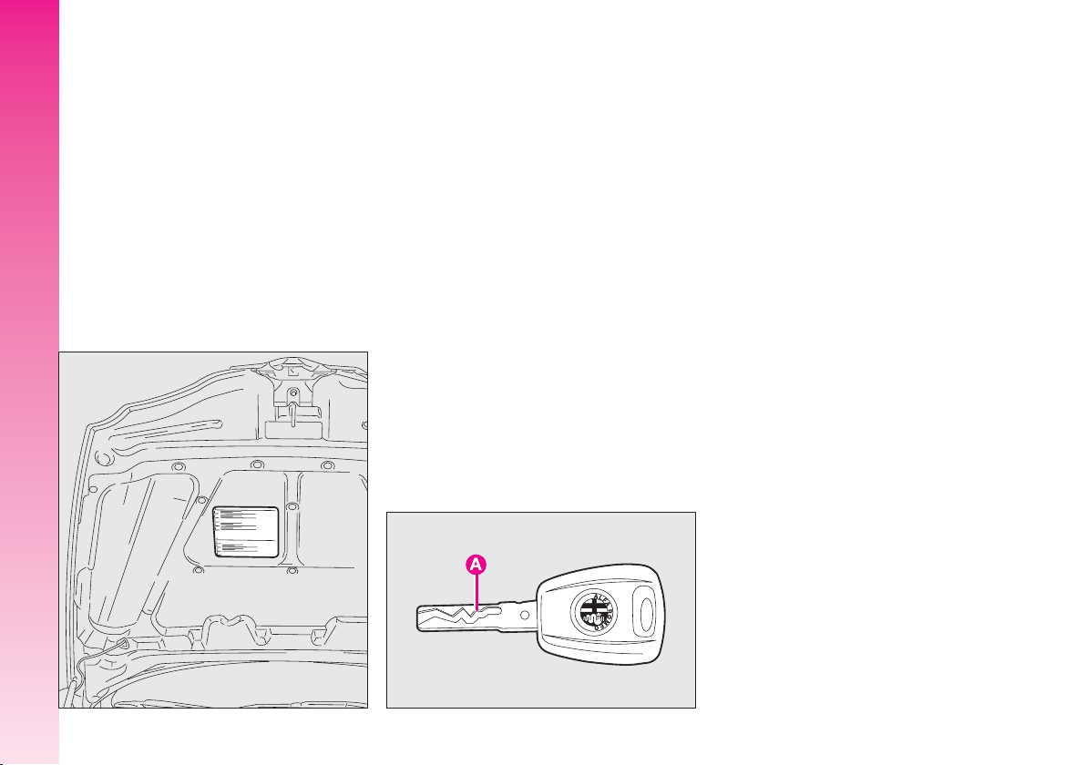
SYMBOLS
On some of the components making up
your
Alfa GT
coloured labels have been attached. These
labels bear symbols that remind you of the
precautions to be taken as regards that particular component. A summary list of the
symbols (fig.1) is to be found under the
bonnet.
GETTING TO KNOW YOUR CAR
, or near to them, special
A0A00621b
THE ALFA ROMEO
CODE SYSTEM
To increase protection against attempted
theft, the car is fitted with an electronic engine lock system (Alfa Romeo CODE) which
is activated automatically when the key is
removed from the ignition. In fact the grip
of each key contains an electronic device
which modulates the radio frequency signal
transmitted when the engine is started by a
special aerial incorporated in the ignition
switch. This modulated signal is the “password” by which the control unit recognises
the key and only in this condition can the
engine be started.
A0A1118b
KEYS
The car is delivered with a key with metal insert (upon request for models/markets
where required) and a key with remote control. For models/markets where required
two keys with remote control can be provided.
KEY WITHOUT REMOTE
CONTROL (for versions/
markets where applicable)
The fixed metallic insert A-fig. 2 operates:
– the ignition switch;
– the driver’s door lock;
– the passenger’s Air bag deactivation (upon request for versions/markets where applicable);
– the fuel filler cap lock.
6
fig. 1
fig. 2
Page 8
IMPORTANT To guarantee the perfect
efficiency of the electronic devices contained
in keys, avoid letting them directly exposed
to sunrays.
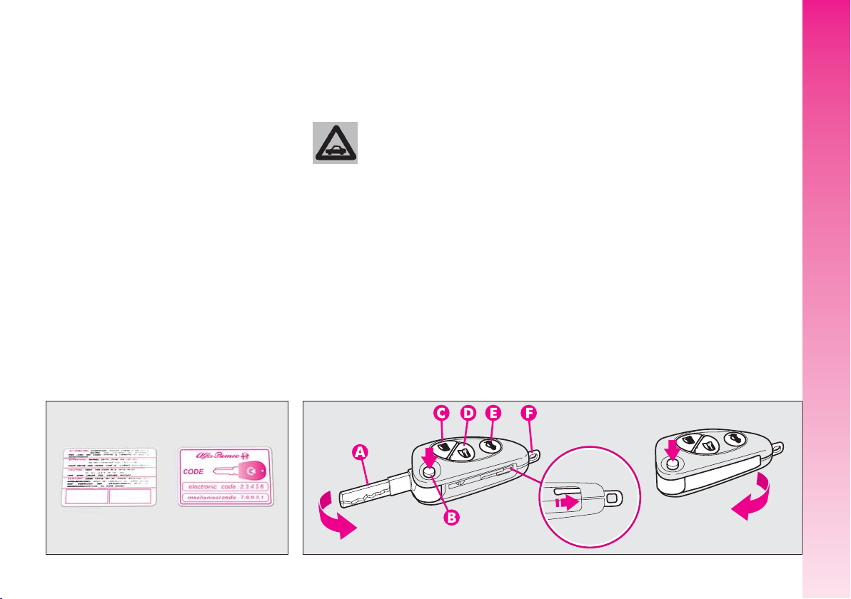
Together with the keys the CODE card is
provided (for versions/ markets where applicable) (fig. 3), bearing in print the key
codes (both mechanical and electronic for
emergency start up).
The code numbers on the CODE card must
be kept in a safe place , not in the car.
The driver should always keep the electronic CODE card with him/her in the event
of having to carry out emergency starting.
If the car changes owner,
the new owner must be
given all the keys and the
CODE card.
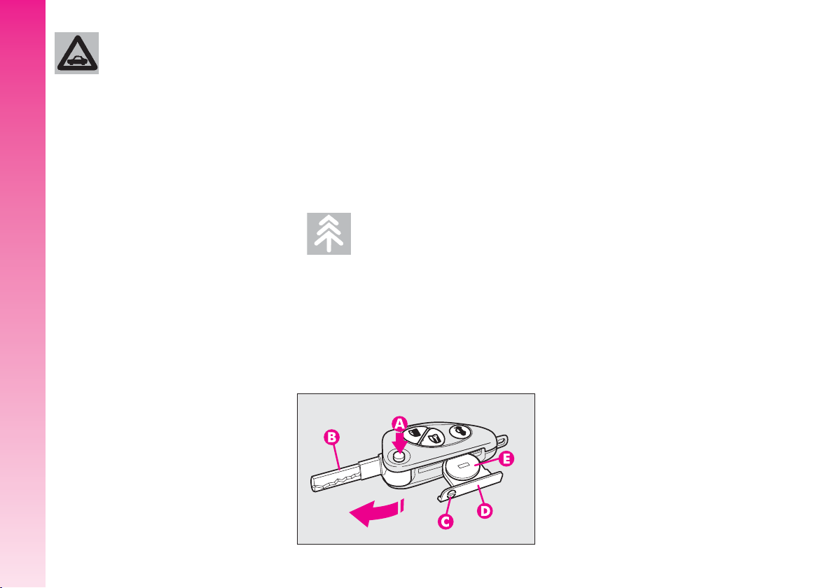
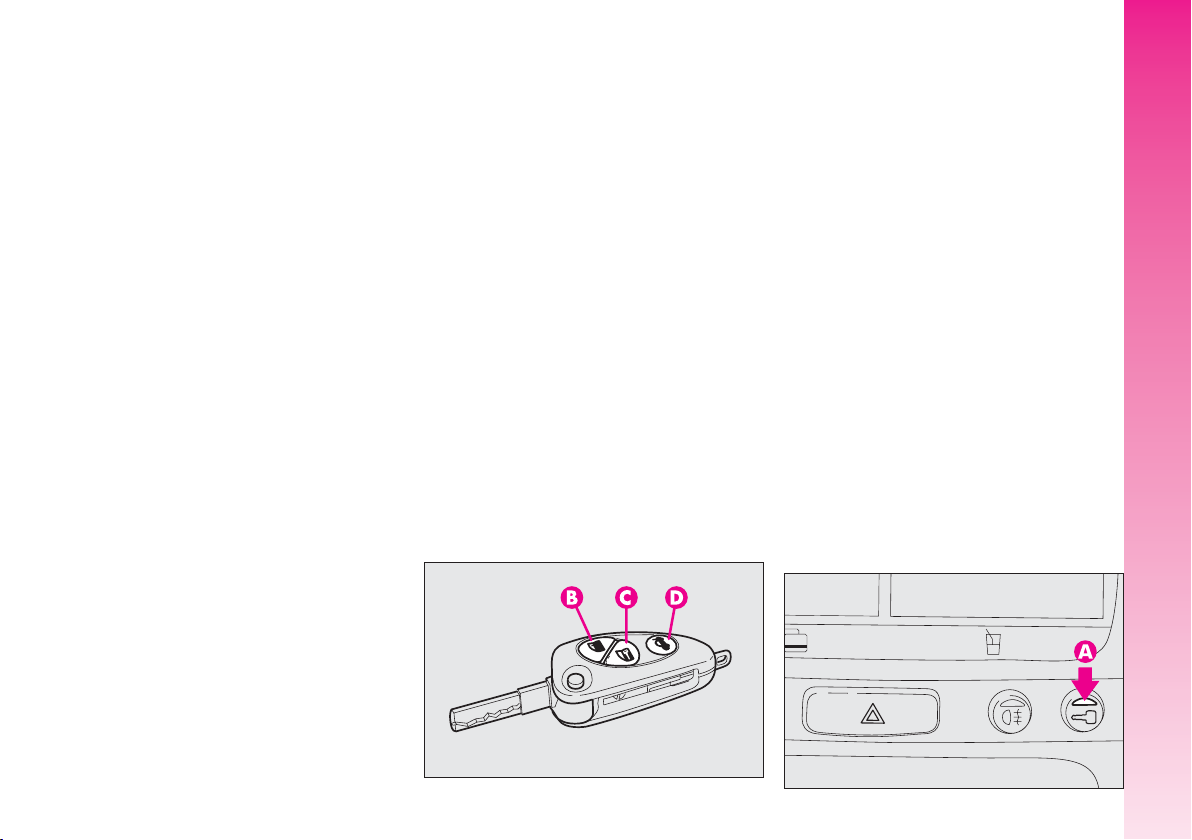
KEY WITH REMOTE CONTROL
The key with remote control (fig. 4) is
fitted with:
– a metal insert (A) that can be enclosed
in the key grip
– a button (B) for power-assisted open-
ing of the metal insert
– a button (C) for remote door unlock-
ing and at the same time switching off the
electronic alarm
– a button (D) for remote door locking
and at the same time switching on the electronic alarm
– a button (E) for remote boot unlocking
– removable hook ring (F).
GETTING TO KNOW YOUR CAR
fig. 3
A0A0003b
fig. 4
A0A0600b
7
Page 9

The metal insert (A) of the key operates:
– the ignition switch
– driver’s door lock and, upon request for
versions/markets where applicable, the passenger’s door lock
– the passenger’s side Air bag deactivation switch
To bring the metal insert out of the key
grip, press the button (B).
To pull out the hook ring (F) use a finely
pointed object (e.g. pen) and work in the
GETTING TO KNOW YOUR CAR
direction of the arrow.
The button B should only
be pressed when the key is
away from the body, in
particular from the eyes, and from
objects that can be spoilt (clothes
for instance). Make sure the key
can never be touched by others, especially children, who may inadvertently press the button.
To insert the metal insert in the key grip:
– keep the button (B) pressed
– move the metal insert (A)
– release the button (B) and turn the met-
al insert (A) until hearing the click as it locks
into place.
To unlock the doors by remote control press
button (C), the doors unlock and the direction indicators flash twice. To lock the doors
by remote control, press button (D), the
doors lock and the direction indicators flash
once. Pressing button (C) the doors are released, if within the next 60 seconds a door
or the tailgate are not opened, the system automatically locks everything again.
On cars fitted with electronic alarm system,
pressing button (C) turns it off, pressing button (D) turns it on.
OPENING THE TAILGATE
The tailgate can be opened from outside by
remote control pressing button (E), even if the
electronic alarm is on. Opening of the tailgate
is accompanied by the direction indicators
flashing twice; closing is accompanied by a
single flash.
If the electronic alarm is fitted, when the
tailgate is opened the alarm system switches off volumetric protection and the tailgate
control sensor, the system (with the exception of versions for certain markets) “beeps”
twice.
Closing the tailgate again, the control functions are restored, the system “beeps” twice
(with the exception of certain markets).
8
Page 10

OPERATION
Each time the ignition key is turned to the
STOP position the Alfa Romeo CODE system
deactivates the functions of the engine electronic control unit.
Each time the car is started turning the ig-
nition key to MAR, the Alfa Romeo CODE
control unit sends a recognition code to the
engine control unit to deactivate the inhibitor. The code is crypted and variable between over four billion possible combinations, and it is sent only if the system control unit has recognised the code transmitted from the key which contains an electronic transmitter, through an aerial wound
around the ignition switch.
If the code has not been recognised correctly, the Alfa Romeo CODE warning light
(
Y
) on the cluster turns on.
In this case, the key should be moved to
the STOP position and then back to MAR;
if the lock continues, possibly try again with
the other key provided with the car. If it is
still not possible to start the car, follow the
instructions given in the “In an emergency”
chapter and then contact Alfa Romeo Authorised Services.
IMPORTANT Every key has its own
code, which must be memorised by the system control unit. To memorise new keys, up
to a maximum of eight, apply solely to Alfa Romeo Authorised Services taking with
you all the keys in your possession, the
CODE card, a personal identity document
and the car’s ownership documents.
The codes of any keys not
presented during the memorising procedure are
erased. The reason for this is to ensure that any lost or stolen keys
cannot be used to start the engine.
IMPORTANT Turning on of the Alfa
Y
Romeo CODE warning light (
) when trav-
elling with the ignition key at MAR:
1) If the warning light turns on, this means
that the system is running a self-test (for example for a voltage drop). At the first stop,
it will be possible to test the system: switch
off the engine turning the ignition key to
STOP; then turn the ignition key to MAR:
the warning light turns on and should go off
in about one second. If the warning light
stays on, repeat the procedure described previously leaving the key at STOP for over
30 seconds. Should the inconvenience persists, contact Alfa Romeo Authorised Services.
2) For versions without the reconfigurable
multifunction display, the flashing of the
warning light means that the car is not protected by the engine inhibitor device. This
condition for cars with reconfigurable multifunction display is shown by the turning on
of the warning light together with the display of the message: “C
GRAMMED”. Contact Alfa Romeo Authorised
ODE SYSTEM NOT PRO-
Services immediately to have all the keys
memorised.
GETTING TO KNOW YOUR CAR
9
Page 11
If after about 2 seconds
with the ignition key at
MAR, for versions without
reconfigurable multifunction display, the Alfa Romeo CODE warning light (
Y
) turns on again flashing, or for versions with reconfigurable multifunction display, the
warning light turns on again together with the message “CODE
SYSTEM NOT PROGRAMMED
”, this
means that the code of the keys
has not been stored, therefore the
car is not protected by the Alfa
GETTING TO KNOW YOUR CAR
Romeo CODE system against attempted theft. In this case contact
Alfa Romeo Authorised Services to
have the key codes stored.
KEY BATTERY
REPLACEMENT
If when pressing button (B or C-fig. 6)
on the remote control, nothing happens, the
battery should be replaced by a new one
of the same type to be found c/o normal
retailers.
Used batteries are harmful to the environment.
They should be disposed of
as specified by law in the special
containers provided. Avoid exposure to naked flames and high temperatures. Keep out of reach of
children.
A0A0603b
Battery replacement:
– press button (A-fig. 5) and move the
metal insert (B) to the open position;
– using a finely-tipped screwdriver, turn
the opening device (C) and pull out the battery holder (D);
– replace the battery (E) making sure that
the bias is correct;
– re-insert the battery holder in the key
and lock it, turning the device (C).
10
fig. 5
Page 12
ELECTRONIC ALARM
DESCRIPTION
The system comprises: a transmitter, receiver, control unit with siren and volumetric sensors. The electronic alarm is controlled
by the receiver incorporated in the instrument cluster and it is turned on and off by
the remote control in the key which sends
the crypted and variable code. The electronic
alarm controls: the unlawful opening of
doors, bonnet and boot (perimetral protection), operation of the ignition key, battery
cable cutting, the presence of moving bodies in the passenger compartment (volumetric protection), any abnormal raising/sloping of the car (for versions/markets where applicable) and central door locking. It also makes it possible to cut off the
volumetric protection.
IMPORTANT The engine inhibitor function is guaranteed by the Alfa Romeo CODE
system which is activated automatically
when the ignition key is removed.
The remote control is incorporated in the
key and it is fitted with buttons (B-C-D-
fig. 6) that activate the corresponding control sending the code to the receiver. This
code (rolling code) changes at each transmission.
REQUEST FOR ADDITIONAL
KEYS WITH
REMOTE CONTROL
The receiver can recognise up to 5 keys
with incorporated remote control. Should a
new key with remote control be necessary
for any reason during the life of the car, contact directly Alfa Romeo Authorised Services,
taking with you the CODE card, a personal
identity document and the car’s ownership
documents.
A0A0601b
HOW TO ACTIVATE THE ALARM
With the doors, bonnet and boot shut and
the ignition key in the STOP or PARK position (key removed), point the key with the
remote control in the direction of the car, then
press and release the button (C-fig. 6).
With the exception of certain markets, the
system sounds a “beep” and the doors are
locked.
Engagement of the alarm is preceded by
a self-diagnostic test indicated by a different
flashing frequency of the deterrent led (A-
fig. 7) on the dashboard. If a fault is detected the system sounds a further warning “beep”.
A0A0005b
GETTING TO KNOW YOUR CAR
fig. 6
fig. 7
11
Page 13

Surveillance
After switching on, the flashing of the de-
terrent led (A-fig. 7) on the dashboard indicates the system surveillance mode. The
led flashes throughout this period.
IMPORTANT Operation of the electronic
alarm is adapted at the origin to the rules
of the different countries.
Self-diagnostic functions
and door, bonnet, boot control
If, after engaging the alarm, a second
GETTING TO KNOW YOUR CAR
“beep” is sounded, switch off the system
pressing the button (B-fig. 6), check that
the doors, bonnet and tailgate are properly
shut, then switch the system on again pressing the button (C). Otherwise, the door,
bonnet or tailgate that is not shut properly
will be excluded from the alarm system control.
If the doors, bonnet and boot are shut correctly and the control signal is repeated, the
system self-diagnostic has detected a system operating fault. It is therefore necessary
to contact Alfa Romeo Authorised Services.
HOW TO DEACTIVATE
THE ALARM
To deactivate the alarm press the button (B-
fig. 6) of the key with remote control. The
system will react as follows (with the exception of certain markets):
– two brief flashes of the direction indi-
cators
– two brief “beeps” of the system
– door unlocking.
IMPORTANT If when the system is
turned off the deterrent led (A-fig. 7) on
the dashboard stays on (maximum 2 minutes or until the ignition key is set to MAR)
the following should be borne in mind:
– if the led continues flashing, but at different intervals than normal, this means that
different attempts to break in have occurred.
Through the number of flashes it is possible to identify the type of attempt:
1 flash: one or more doors
2 flashes: tailgate
3 flashes: bonnet
4 flashes: ultrasounds
5 flashes: abnormal car lifting/slop-
ing (for versions/markets
where applicable)
6 flashes: tampering with car starting
cables
7 flashes: tampering with battery ca-
bles or cutting emergency
key cables
8 flashes: connection line to sensors
and siren
9 flashes: at least three causes of
alarm.
12
Page 14

WHEN THE ALARM IS
TRIGGERED
When the system is on, the alarm comes
into action in the following cases:
– opening of one of the doors, bonnet or
tailgate;
– disconnection of the battery or section-
ing of electric cables;
– intrusion in the passenger compartment,
for example breakage of windows (volumetric protection);
– attempt to start the engine (key in
MAR position);
– abnormal car lifting/sloping (for versions/markets where applicable).
Depending on the markets, the cutting in
of the alarm causes operation of the siren
and hazard warning lights (for about 26 seconds). The ways of operating and the number of cycles may vary depending on the
markets.
A maximum number of cycles is however
envisaged.
Once the alarm cycle has ended, the system resumes its normal control function.
VOLUMETRIC PROTECTION
To make sure that the protection system
works correctly the side windows and sunroof (if fitted) must be properly shut.
The function can be cut off (if, for example, leaving animals in the car) carrying out
the following operations in rapid succession:
starting from the condition with the ignition key at MAR, move the key to STOP,
then immediately back to MAR and then
to STOP again, then remove the ignition
key.
The deterrent led (A-fig. 7) on the dashboard lights up for about 2 seconds to confirm that the function has been cut off.
To restore volumetric protection, move the
and keep the ignition key at MAR for over
30 seconds.
If, with the volumetric protection function
deactivated, an electric control controlled by
the ignition key at MAR (e.g. power windows) turn the ignition key to MAR, operate the control and move the key to
STOP in a maximum time of 30 seconds.
This way volumetric protection is not restored.
HOW TO CUT OFF
THE ALARM SYSTEM
To deactivate the alarm system completely (for instance during prolonged inactivity
of the car) simply lock the car turning the
key in the lock.
MINISTERIAL CERTIFICATION
In accordance with the law in force in each
country, on the subject of radio frequency,
we wish to point out that for the markets in
which the transmitter needs to be marked,
the certification number is given on the component.
Depending on the versions/markets, the
code may also be given on the transmitter
and/or on the receiver.
GETTING TO KNOW YOUR CAR
13
Page 15
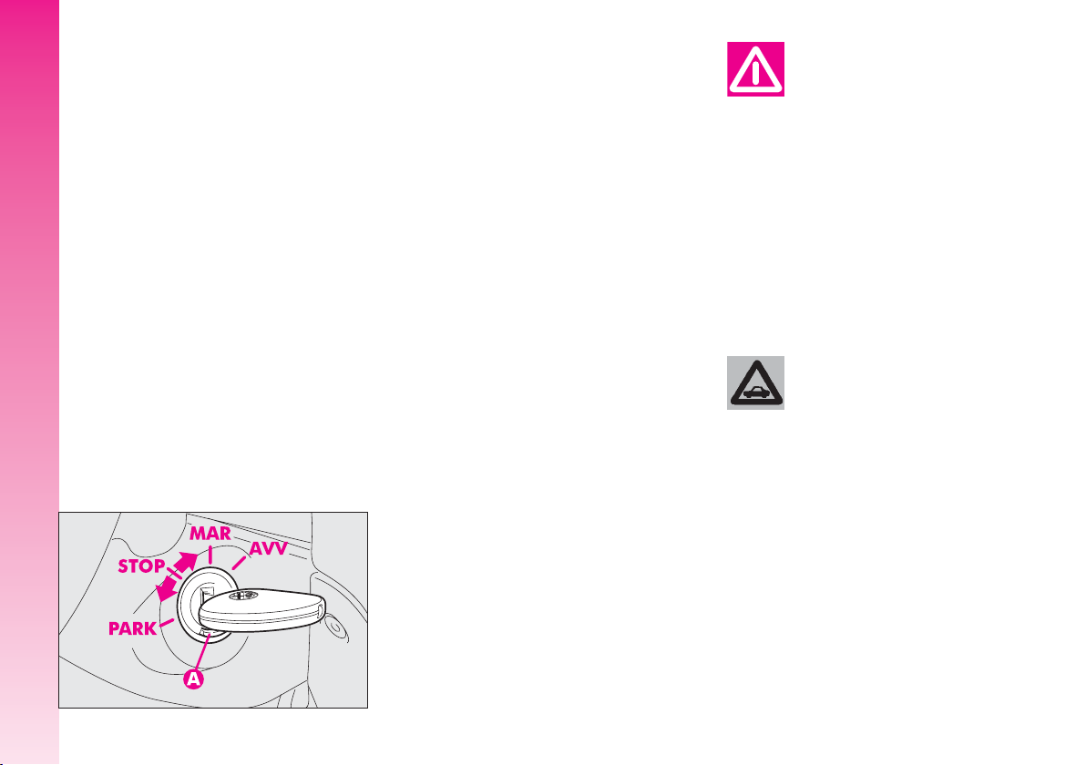
IGNITION DEVICE
SWITCH
The key can be turned to one of four po-
sitions:
– STOP: engine switched off, key can be
removed, engine inhibitor engaged, steering lock engaged, services excluded apart
from those supplied directly (e.g. hazard
warning lights).
– MAR: drive position. The engine lock
GETTING TO KNOW YOUR CAR
is deactivated and all electrical devices are
powered.
(fig. 8)
A0A0016b
IMPORTANT Do not leave the key in
this position when the engine is stopped.
– AVV: unstable position for starting the
engine.
IMPORTANT If the engine fails to start
move the key back to STOP and repeat.
The ignition switch has a safety device
which prevents passage to AVV when the
engine is running.
– PARK: engine switched off, key can
be removed, engine lock engaged, steering lock engaged, sidelights switched on automatically.
IMPORTANT To turn the key to the
PARK position, button (A) on the switch
must be pressed first.
When leaving the car always remove the key from
the ignition to prevent any
occupants of the car from accidentally activating the controls. Never leave children in the car unaccompanied. Remember to engage
the handbrake and, if the car is
parked on an uphill slope, to engage the first gear. If the car is facing downhill, engage reverse gear.
If the ignition device is
tampered with (for example an attempted theft)
have it checked over by Alfa
Romeo Authorised Services before
travelling again.
14
fig. 8
Page 16
STEERING LOCK
Engaging:
– move the key to STOP orPARK, then
remove the key and turn the steering wheel
slightly to facilitate the locking action.
Disengaging:
– turn the key to MAR gently rocking the
steering wheel from side to side.
Never remove the ignition
key with the car on the
move. The steering wheel
would lock automatically the first
time the steering wheel is turned.
This also occurs if the car is towed.
It is absolutely forbidden
to carry out whatever after-market operation in-
volving steering system or steering column modifications (e.g.: installation of anti-theft device) that
could badly affect performance and
safety, cause the lapse of warranty and also result in non-compliance of the car with homologation
requirements.
DOORS
Before opening a door, always make sure that it can
be done safely.
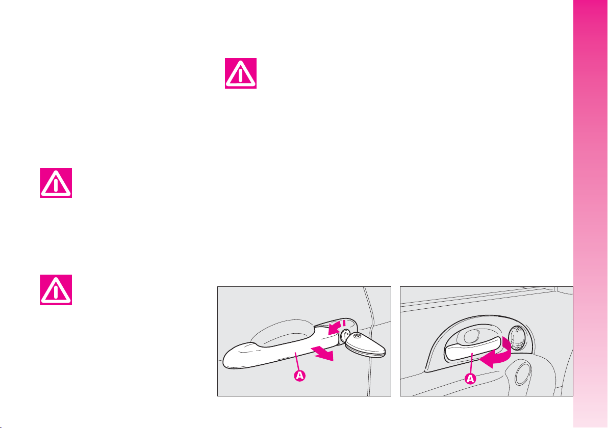
OPENING/CLOSING
FROM OUTSIDE
Front doors
– To open the door, turn the key (clockwise
for the driver’s door and, upon request for versions/markets where applicable, counterclockwise for the passenger’s door), then remove the key and pull the lever (A-fig. 9).
– To close the door, turn the key in the
lock in the opposite direction to the one for
opening.
fig. 9
A0A0017b
OPENING/CLOSING
FROM INSIDE
Front doors
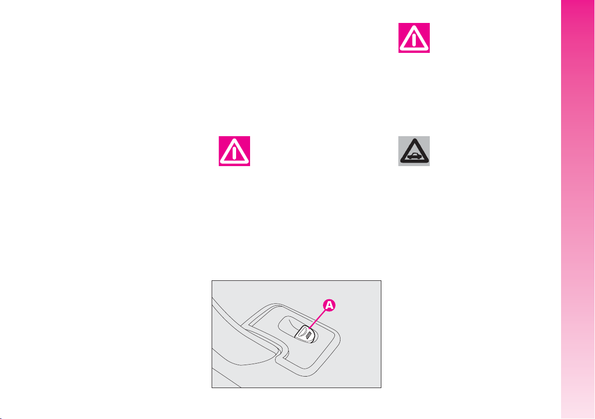
– To open the door, pull the handle
(A-fig. 10).
– To close the door, pull it; then to prevent
opening from the outside, press the button
(A-fig. 11) on the dashboard, the deterrent led (B) on the button lights up with a
yellow light to confirm that locking has taken place.
fig. 10
GETTING TO KNOW YOUR CAR
A0A0018b
15
Page 17
CENTRAL LOCKING
This allows central locking of the door
locks.
To engage central locking, the doors must
be perfectly shut, otherwise locking is denied.
IMPORTANT With central locking engaged, pulling the inside lever for opening
one of the front doors causes the unlocking of all the doors.
In the event of a power cut off (blown
fuse, battery disconnected, etc.) it is still pos-
GETTING TO KNOW YOUR CAR
sible to work the lock by hand.
fig. 11
16
A0A0019b
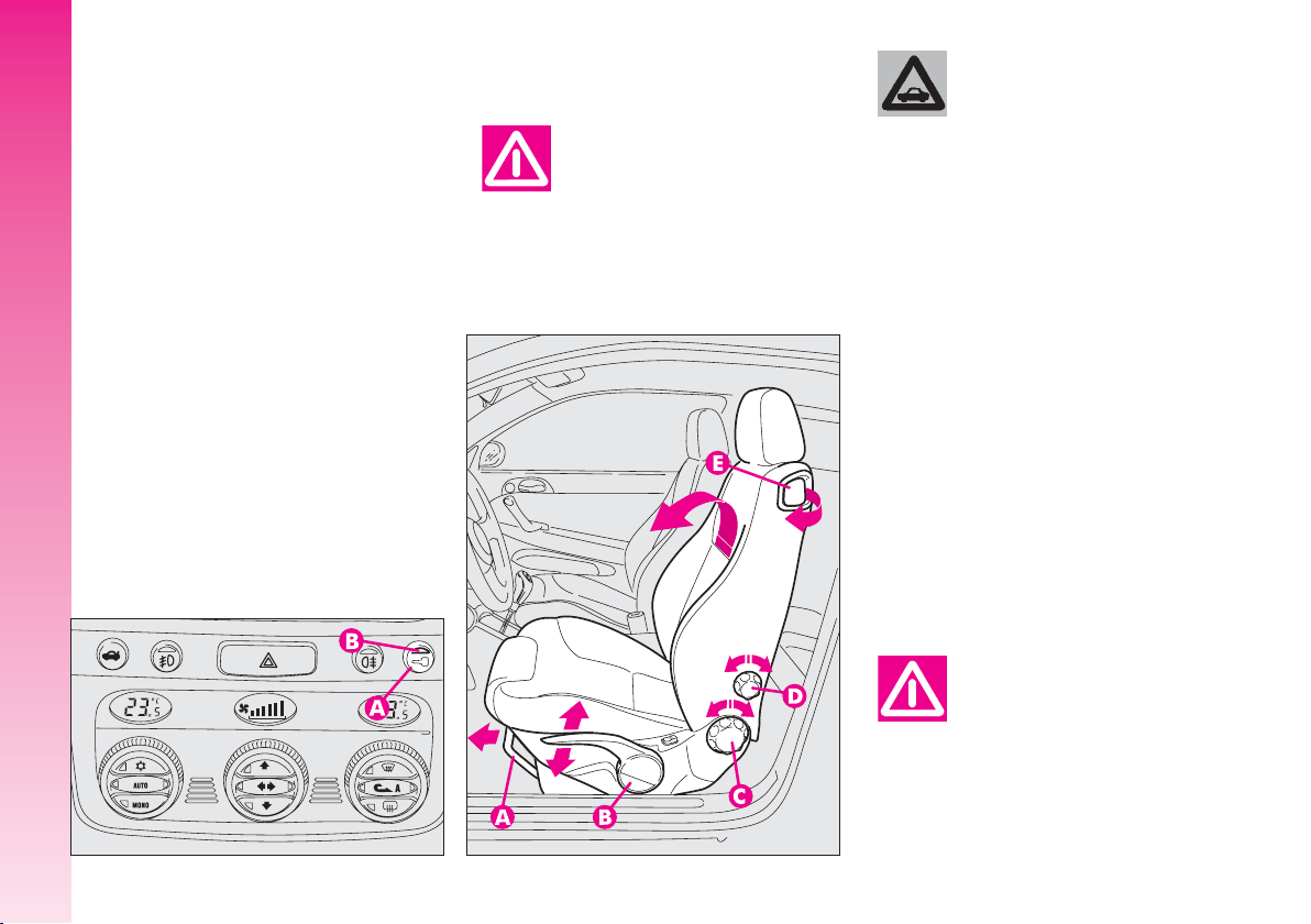
FRONT SEATS
Only make adjustments
when the car is stationary.
fig. 12
A0A0602b
Fabric upholstery of your
car is purpose-made to
withstand common wear
resulting from normal use of the
car. It is however absolutely necessary to prevent hard and/or prolonged scratching/scraping caused
by clothing accessories like metallic buckles, studs, “Velcro” fixings,
etc. that stressing locally the fabric
could break yarns and damage the
upholstery as a consequence.
LENGTHWISE ADJUSTMENT
(
fig. 12
backwards or forwards; in the driving position the arms should be slightly flexed and
the hands should rest on the rim of the steering wheel.
locked on the runners, trying to
move it to and fro. The lack of this
clamping action could cause the
seat to move unexpectedly and
cause loss of car control.
)
Raise the lever (A) and push the seat
After releasing the adjustment lever, always
check that the seat is
Page 18
DRIVER’S SEAT LUMBAR
ADJUSTMENT(fig. 12
Turn the knob (D) until obtaining the most
comfortable position.
DRIVER’S SEAT HEIGHT
ADJUSTMENT(fig. 12
To raise the seat, pull the lever (B) up-
wards, then work the lever (up and down)
until reaching the required height, then release it. To lower the seat, push the lever
(B) downwards, then work the lever (up
and down) until reaching the required
height.
IMPORTANT Adjustment must be car-
ried out only seated in the driver’s seat.
)
)
TILTING THE BACK REST (fig. 12
To gain access to the rear seats, pull the
handle (E), the back rest folds and the seat
is free to run forwards.
A recovery mechanism with memory
makes it possible to take the seat back to
its previous position.
Once the seat back has been returned to
the travelling condition, make sure that it
is correctly clamped, checking that the “red
band” on the upper part of the handle (E)
is concealed. In fact, this “red band” indicates that the seat back is not clamped.
Also check that the seat is firmly locked on
the runners, trying to move it to and fro.
BACK REST ANGLE
ADJUSTMENT
Turn the knob(C) until reaching the position required.
(
fig. 12
)
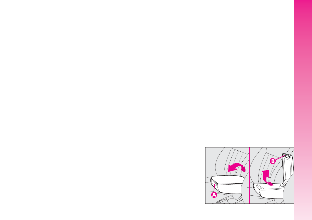
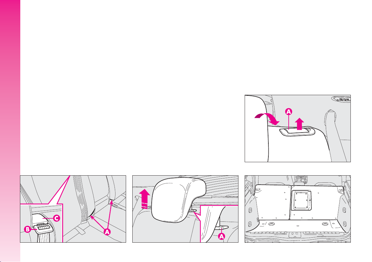
CENTRAL ARMREST (
)
The armrest, fitted on some versions, is adjustable and can be raised and lowered to
the required position.
To adjust, slightly raise the armrest, then
press the the release device (A).
Inside the armrest there is an oddments
compartment, to use it, raise the cover,
pressing the device (B).
fig. 13
)
GETTING TO KNOW YOUR CAR
A0A0023b
fig. 13
17
Page 19
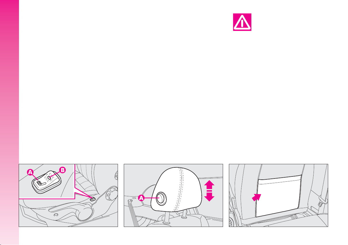
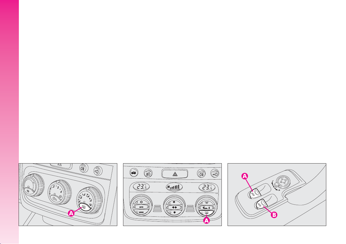
SEAT WARMING (fig. 14
)
Seat warming, fitted on certain versions,
is turned on and off through the switch (A)
on the outer side of the seat.
Switching on is shown by the lighting up
of the led (B) on the switch itself.
GETTING TO KNOW YOUR CAR
HEADREST ADJUSTMENT
(
fig. 15
)
To increase passengers’ safety, the head-
rests are adjustable in height.
To adjust, press the button (A) and move
the headrest up or down until it clicks into
place.
IMPORTANT The configuration of the
headrest cushion may vary depending on
the versions and markets. The purpose of
the illustration is only to show how it is adjusted.
Remember that headrests
should be adjusted so that
the nape, and not the neck,
rests on them. Only in this position
do they exert their protective action in the event of a crash from
behind.
REAR POCKETS (fig. 16
(for versions/markets where
applicable)
The front seats are fitted with a pocket in
the rear of the back rest.
)
18
fig. 14
A0A0024b
fig. 15
A0A0604b
A0A0026b
fig. 16
Page 20
REAR SEATS
Fabric upholstery of your
car is purpose-made to
withstand common wear
resulting from normal use of the
car. It is however absolutely necessary to prevent hard and/or prolonged scratching/scraping caused
by clothing accessories like metallic buckles, studs, “Velcro” fixings,
etc. that stressing locally the fabric
could break yarns and damage the
upholstery as a consequence.
EXTENDING THE
LUGGAGE COMPARTMENT
The split of rear seat makes it possible to
extend the luggage compartment totally or
partially, acting separately on one of the two
parts, thereby offering different possibilities
of load depending on the number of rear
passengers.
If a particularly heavy
load is placed in the boot,
when travelling at night, it
is wise to check the height of the
high beams (see “Headlamps”
paragraph).
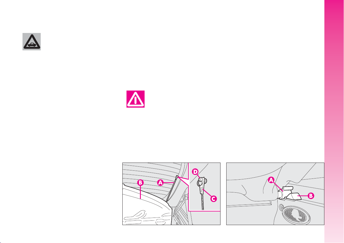
Removing the rear parcel shelf
Proceed as follows:
– free the ends of the two rods (A-fig. 18)
supporting the parcel shelf (B) pulling the
eyelets (C) off the pins (D);
– release the pins (A-fig. 19) at the outside of the shelf from their housings (B) obtained in the side supports, then remove the
shelf pulling it outwards.
GETTING TO KNOW YOUR CAR
fig. 18
A0A0605b
fig. 19
A0A0255b
19
Page 21
Total extension
Proceed as follows:
– check that seat buckles of the side belts
are fitted in the respective pockets on the
back rest (A-fig. 20) and the tab (B)
of the centre abdominal belt is inserted in
the support (C).
– pull the handles in the centre of the cush-
ions, then tilt them forwards;
GETTING TO KNOW YOUR CAR
– raise the headrest to the highest posi-
tion, press both buttons (A-fig. 21) at the
side of the two supports, then remove the
headrest pulling them upwards;
– move the seat belts to the side extend-
ing them correctly without twisting;
– raise the levers (A-fig. 22) retaining
the back rests and tilt them forwards to obtain a single loading surface (fig. 23).
IMPORTANT For versions/markets
where applicable, the retainer levers are replaced by buttons (one for each side). To release the back rests and tilt them, use the
buttons themselves.
A0A0608 b
20
fig. 20
A0A0623b
fig. 21
A0A0607b
fig. 22
A0A0608 b
fig. 23
Page 22
Partial extension
For partial extension, proceed as follows:
– tilt the cushion required pulling the handle at the centre of the cushion, then tilting the actual cushion;
– move the seat belt to one side extending it correctly without twisting;
– raise the lever retaining the back rest
and tilt it forwards.
To bring the seat back to its
normal position
Proceed as follows:
– move the seat belts to one side extending them correctly without twisting;
– raise the seat backs, pushing them backwards until hearing both clamping devices
click into place;
– set the cushions to the horizontal position keeping the centre seat belt raised.
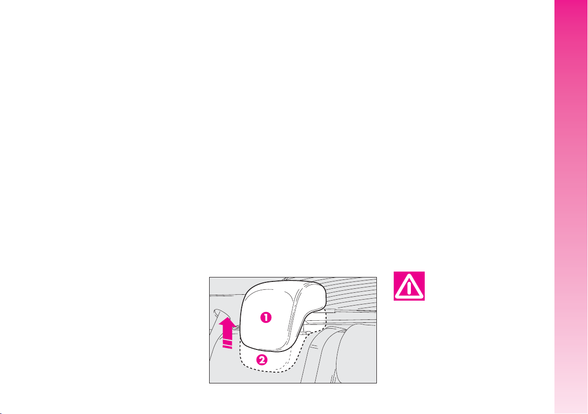
HEADREST ADJUSTMENT
(
fig. 24
for the side seats and, depending on the trim
level, it may also have a third headrest in
the centre.
“non use position” and reach the (1) “all
removed” position. To restore the “non use
position”, press button (A-fig. 21) and
push the headrest downwards.
)
The car may be fitted with two headrests
To use the headrest, raise it from the (2)
All rear headrests can be removed.
A0A0610b
The particular headrest shape interferes intentionally with the rear passenger’s correct
position on the back rest; this forces the passenger to raise the headrest to use it correctly.
IMPORTANT When using rear seats,
the headrests shall be kept in the “all removed” position.
GETTING TO KNOW YOUR CAR
Remember that headrests
should be adjusted so that
the nape, and not the neck,
rests on them. Only in this position
do they exert their protective action in the event of a crash from
behind.
fig. 24
21
Page 23
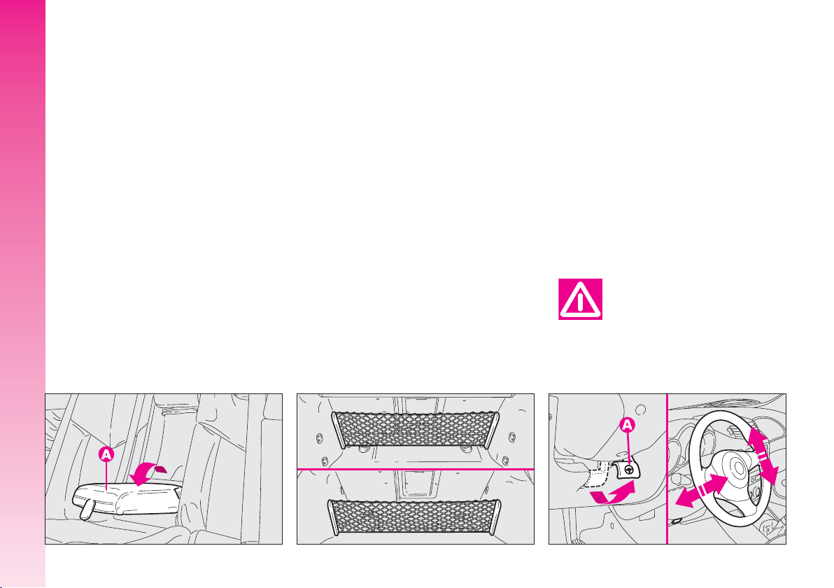
CENTRAL ARMREST (fig. 25
To use the armrest (A), present only on
certain versions, lower it as illustrated.
GETTING TO KNOW YOUR CAR
)
LUGGAGE
STEERING WHEEL
RETAINER NET
(where provided)
Present only on certain versions, the re-
tainer net (fig. 26) is helpful in correctly
arranging the load and/or suitable for transporting light materials.
The driver can adjust the steering wheel
position in rake and height.
To do this, release the lever (A-fig. 27)
pulling it towards the steering wheel.
After moving the steering wheel to the
most suitable position, lock it pushing the
lever fully forwards.
Any adjustment of the
steering wheel position
must be carried out only
with the car stationary.
22
fig. 25
A0A0611b
fig. 26
A0A0624b
A0A0706b
fig. 27
Page 24
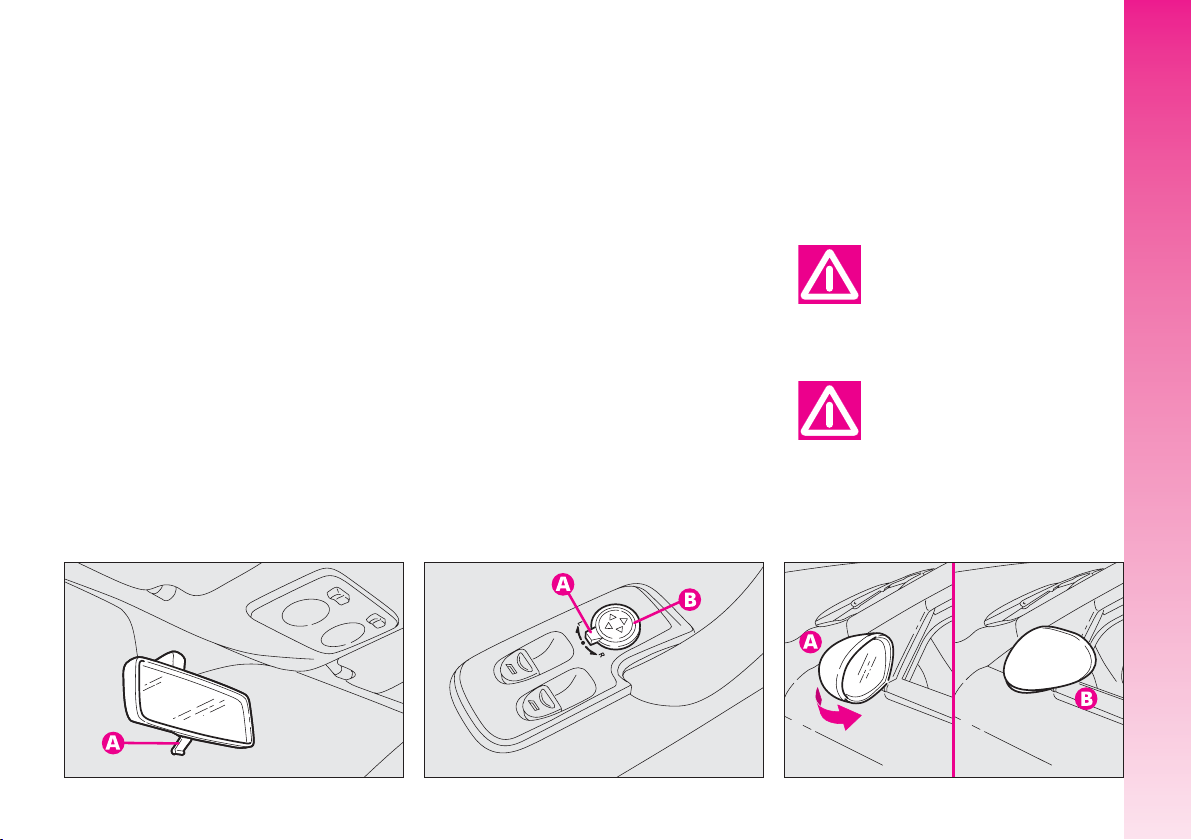
REAR-VIEW MIRROR
ADJUSTMENT
INNER
The mirror, fitted with a safety device that
causes it to be released in the event of a
violent crash, can be moved using the lever
(A-fig. 28) to two different positions, normal or antiglare.
OUTER
Electric adjustment
– use the switch (A) to select the mirror
required (right or left);
– pressing the button (B) in one of the
four directions, move the mirror selected previously;
– position the switch (A) in the interme-
diate locking position.
IMPORTANT Adjustment is possible on-
ly with the ignition key at MAR.
(
fig. 29
)
Folding(fig. 30
– In the event of need (for example when
the mirror causes difficulty in narrow spaces)
it is possible to fold the mirror moving it from
position (A) to position (B).
When driving the mirrors
should always be in position (A).
As the driver’s wing mirror is curved, it may slightly alter the perception of
distance.
)
GETTING TO KNOW YOUR CAR
fig. 28
A0A0039b
fig. 29
A0A0040b
fig. 30
A0A0041b
23
Page 25
Defrosting/demisting
(
fig. 31-32
The electric mirrors are fitted with heat-
ing coils which come into operation with
rearscreen heating pressing the button (A)
thereby defrosting and/or demisting the mirrors.
IMPORTANT The function is timed and
automatically switched off after a few minutes.
GETTING TO KNOW YOUR CAR
)
POWER WINDOWS
IMPORTANT With the ignition key at
STOP or removed, the power windows re-
main activated for about 3 minutes and are
deactivated immediately the moment a door
is opened.
Driver’ side (fig. 33)
The driver’s door panel contains the but-
tons that control the following windows,
with the ignition key at MAR:
A - left front window
B - right front window.
Press the button to lower the window. Pull
to raise it.
24
fig. 31
A0A0042b
fig. 32
A0A0612b
A0A0043b
fig. 33
Page 26
IMPORTANT The driver’s power window
is fitted with the “continuous automatic operation” device for both lowering and raising
the window. A brief press on the upper or
lower part of the button will cause it to move
and continue automatically: the window
stops in the required position by pressing either the upper or lower part of the button
again. The passenger window is fitted with
“automatic continuous operation” device just
for window opening.
Passenger’s side (fig. 34
The button (A) controls the passenger’s
side window.
Button and window operation is the same
as that described for driver’s side.
Improper use of the power windows can be dangerous. Before and during its
operation, always make sure that
passengers are not exposed to the
risk of harm either directly by the
moving windows or by personal
objects drawn or knocked by them.
)
A0A0044b
Always remove the ignition key when getting out
of the car to prevent the
power windows being operated accidentally and constituting a danger
to the passengers in the car.
Do not keep the button
pressed when the window
is completely raised or
lowered.
GETTING TO KNOW YOUR CAR
fig. 34
25
Page 27
For all versions, after unlocking the doors,
keeping the remote control button pressed
for about 2 seconds will obtain window
opening.
IMPORTANT For versions/markets
where applicable, after turning off control
unit power (replacing or disconnecting the
battery or replacing the power window control unit protection fuses), window automatism shall be restored.
GETTING TO KNOW YOUR CAR
Proceed as follows with doors closed:
1. open completely the driver’s window
keeping the button pressed for at least
3 seconds after full opening;
2. close completely the driver’s window
keeping the button pressed for at least
3 seconds after full closing;
3. proceed as described in points 1 and
2 also for the passenger’s side;
4. check for proper initialisation by oper-
ating the windows in automatic.
SEAT BELTS
USING THE SEAT BELTS
The belt should be worn keeping the chest
straight and rested against the seat back.
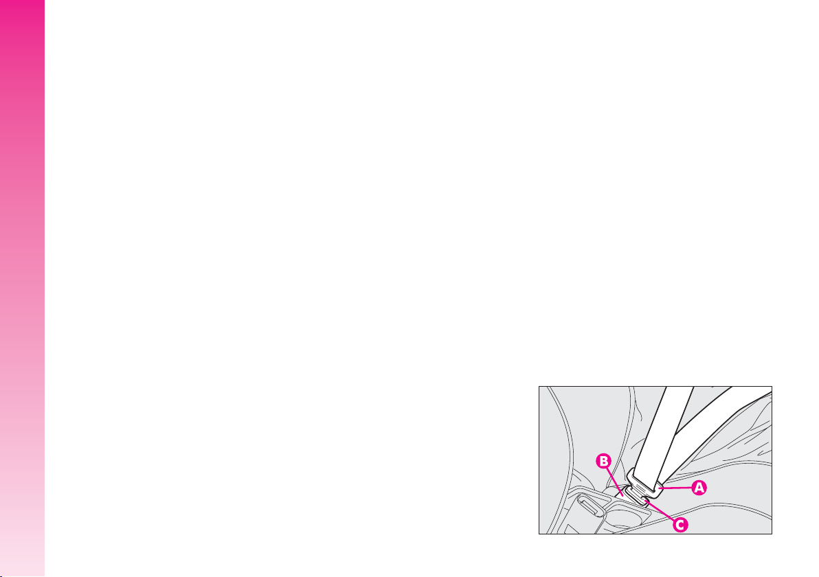
To fasten the seat belts: hold the
tongue (A-fig. 35) and insert it into the
buckle (B), until hearing the locking click.
At removal, if it jams, let it rewind for a short
stretch, then pull it out again without jerking.
A0A0045b
26
fig. 35
Page 28
To unfasten the seat belts: press
button (C-fig. 35). Guide the seat belt
with your hand while it is rewinding, to prevent it from twisting. Through the reel, the
belt automatically adapts to the body of the
passenger wearing it, allowing freedom of
movement.
When the car is parked on a steep slope
the reel mechanism may block; this is normal. The reel mechanism prevents the webbing coming out when it is jerked or if the
car brakes sharply, in a collision or when cornering at high speed.
FRONT SEAT BELT HEIGHT
ADJUSTMENT
Always adjust the height of the belts adapting it to the person who is wearing it. This
precaution improves their effectiveness substantially reducing the risk of injury in the
event of a crash.
Correct adjustment is obtained when the
belt passes half way between the end of the
shoulder and the neck.
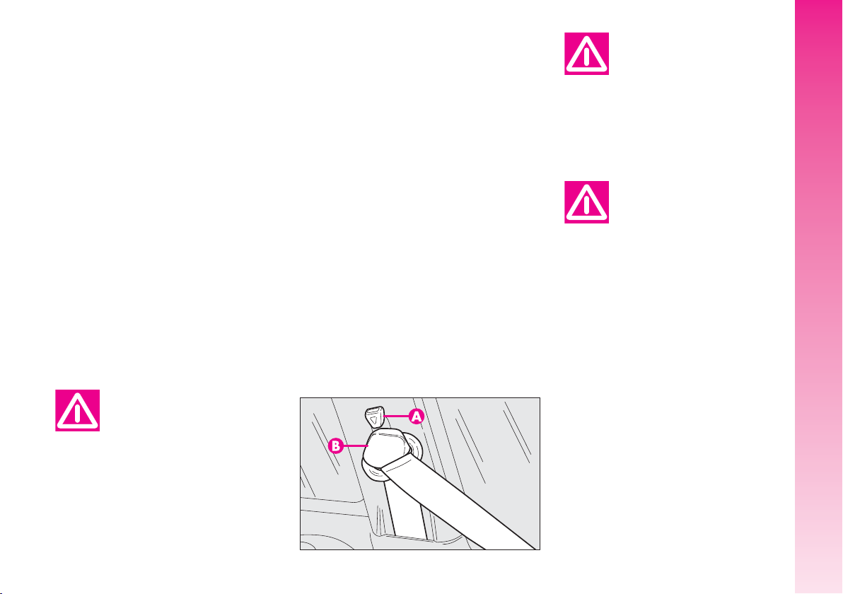
The front seat belt ring can take 4 different positions which make it possible to adjust the height of the belts.
To adjust, press button (A-fig. 36) and
lower or raise the grip (B).
Always adjust the seat
belt height when the car is
stationary.
After adjustment, always
check that the slider is anchored in one of the posi-
tions provided. To do this, with the
button (A) released, exert a further pressure to allow the anchor
device to catch if release did not
take place at one of the preset positions.
GETTING TO KNOW YOUR CAR
Never press button (C)
when travelling.
fig. 36
A0A0685b
27
Page 29
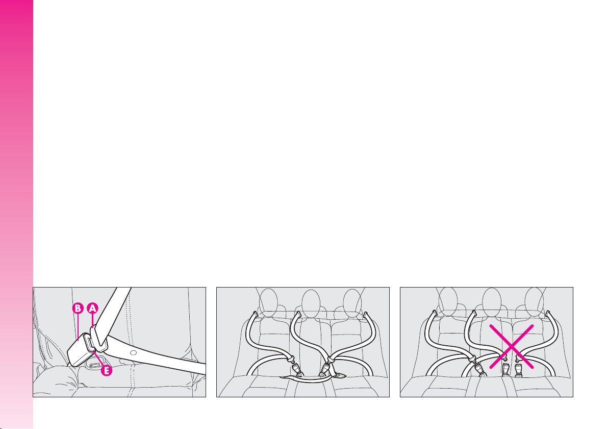
REAR BELTS
To fasten the belt: gently pull the belt from
its reel and guide the tape to prevent it from
twisting, then insert the tongue (A-fig. 37)
into the buckle housing (B).
To unfasten the seat belts, press button (E).
GETTING TO KNOW YOUR CAR
Rear seat belts shall be worn as shown in
fig. 38. Fig. 39shows improper belt fastening. To tilt the back rest see paragraph
“Boot extension”.
IMPORTANT The centre rear seatbelt is
installed on request only for versions/markets on which it is required.
IMPORTANT Remember that, in the
event of an accident, any passengers occupying the rear seats who are not wearing
a seat belt not only subject themselves to
great personal risk, but constitute a danger
to the occupants of the front seats.
PRE-TENSIONING DEVICES
To increase the efficiency of the front seat
belts, the car is fitted with pre-tensioning devices. These devices “feel” that the car is
being subject to a violent impact by way of
a sensor and rewind the seat belts a few
centimetres. In this way they ensure that
the seat belt adheres to the wearer before
the restraining action begins.
The seat belt locks to indicate that the device has intervened; the seat belt cannot be
drawn back up even when guiding it manually.
IMPORTANT The pretensioner will give
maximum protection when the seat belt adheres snugly to wearer’s chest and hips.
28
fig. 37
A0A0686b
fig. 38
A0A0386b
A0A0387b
fig. 39
Page 30
Pretensioner activation may produce a
small amount of smoke. This smoke is in no
way toxic and presents no fire hazard.
The emergency tensioning retractor needs
no maintenance or lubrication. Any modification to its original features will nullify the
retractor effectiveness. If, due to unusual
natural events (floods, high waves, etc.),
the device has been affected by water and
mud, it must be replaced.
Pre-tensioning devices can
only be used once. After
they have been triggered
contact Alfa Romeo Authorised Services to have them replaced. The
validity of the device is 10 years
from the date of production on the
sticker; the pretensioners should be
changed at an Alfa Romeo Authorised Service as this date approaches.
Operations involving banging, vibrations or heating
(above 100°C for a maxi-
mum of 6 hours) in the area of the
pretensioners may damage or trigger off the device. Vibrations from
rough road surfaces or accidental
jolting caused by mounting pavements etc. do not have any effect on
the pretensioner. If, however, you
need assistance, go to Alfa Romeo
Authorised Services.
LOAD LIMITERS
To increase passengers’ protection in the
event of an accident, the front and rear
(where provided) seat belt reels contain a
load limiter which allows controlled sag in
such a way as to dose the force acting on
the shoulders and chest during the belt restraining action in case of a crash.
GENERAL INSTRUCTIONS
FOR THE USE OF THE SEAT
BELTS
All the occupants of the car are obliged to
respect the local traffic laws regarding the
wearing of seat belts.
Always fasten the seat belts before starting.
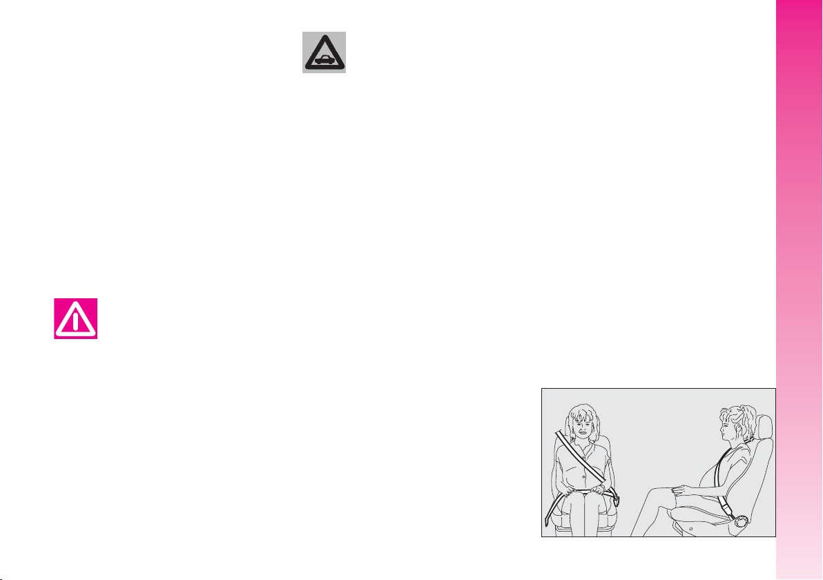
Seat belts are also to be worn by expectant mothers: the risk of injury in the case
of accident is greatly reduced for them and
the unborn child if they are wearing a seat
belt. Pregnant women must of course position the lower part of the belt very low down
so that it passes under the abdomen (as illustrated in fig. 40).
GETTING TO KNOW YOUR CAR
A0A0675b
fig. 40
29
Page 31

IMPORTANT The seat belt must not be
twisted. The upper part must pass over the
shoulder and diagonally across the chest. The
lower part must rest across the pelvis and not
across the (fig. 41) stomach. Do not use
devices (clips, stoppers, etc.) which keep the
belts away from the body.
GETTING TO KNOW YOUR CAR
To ensure the highest degree of protection, you are
recommended to keep the
seat backrest in the straightest position possible, and the belt adhering well to the chest and pelvis.
Seat belts should always be worn
in both the front and rear positions!
Travelling without seat belt increases the risk of serious injury or
death in the case of accident.
IMPORTANT Each seat belt shall be worn
only by one person: do not carry children on
your knee using a single seat belt for both
(fig. 42). Do not fasten other objects to the
body.
Under no circumstances
should the components of
the seat belt and preten-
sioner be tampered with or removed. Any operation should be
carried out by qualified and authorised personnel. Always contact an
Alfa Romeo Authorised Service.
30
fig. 41
A0A0673b
A0A0051b
fig. 42
Page 32

If the seat belt has been
subjected to shock, for example during an accident, it
must be completely replaced together with the attachments and
their screws, and the pretensioning devices, even if visible defects
are not detected, as the belt may
have lost its resilience.
HOW TO KEEP THE SEAT BELTS
ALWAYS IN EFFICIENT
CONDITIONS
To keep the seat belts always in efficient
conditions, observe the following:
– always use the belts with the tape well
taut and never twisted; make sure that it
is free to run without impediments;
– after a serious accident, replace the belt
being worn at that time, even if it does not
appear damaged. Always replace the seat
belts if pretensioners have been activated;
– to clean the belts, wash by hand with
neutral soap, rinse and leave to dry in the
shade. Never use string detergents, bleach
or dyes or any other chemical substance that
might weaken the fibres;
– prevent the reels from getting wet: their
correct operation is only guaranteed if water does not get inside;
– replace the seat belt if it shows significant wear or cut signs.
GETTING TO KNOW YOUR CAR
31
Page 33

CARRYING
CHILDREN SAFELY
For optimal protection in the event of a
crash, all passengers must be seated and
wearing adequate restraint systems. This is
even more important for children.
This prescription is compulsory in all EC
countries according to EC Directive
2003/20/EC.
Compared with adults, their head is proportionally larger and heavier than the rest
GETTING TO KNOW YOUR CAR
of the body, while the muscles and bone
structure are not completely developed.
Therefore, correct restraint systems are necessary, other than adult seat belts.
The results of research on the best protection for a child are summarised in European Standard ECE- R44, which in addition
to making them compulsory, subdivides restraint systems into five groups:
Group 0 0 - 10 kg in weight
Group 0+ 0 - 13 kg in weight
Group 1 9 - 18 kg in weight
Group 2 15 - 25 kg in weight
Group 3 22 - 36 kg in weight
As it may be noted, the groups overlap
partly and in fact, in commerce it is possible
to find devices that cover more than one
weight group. All restraint devices must bear
the certification data, together with the control brand, on a solidly fixed label which
must absolutely never be removed.
Over 1.50 m in height, from the point of
view of restraint systems, children are considered as adults and wear the seat belts
normally. Lineaccessori Alfa Romeo offers
seats for each weight group, which are the
recommended choice, as they have been designed and experimented specifically for Alfa Romeo cars.
Never place cradle child’s
seats facing backwards on
the front passenger seat of
cars fitted with passenger’s air bag
since the air bag activation could
cause serious injuries, even mortal.
You are advised to carry children
always on the rear seat, as this is
the most protected position in the
case of a crash.
SERIOUS DANGER
Children may placed
on the front seat of
cars fitted with passenger’s air bag
deactivation. In this case, it is absolutely necessary to check the
warning light F on the instrument panel to make sure that deactivation has actually took place
(see paragraph “Front passenger
air bag”). The front passenger’s
seat shall be adjusted in the most
backward position to prevent any
contact between child’s seat and
dashboard.
32
Page 34

GROUP 0 AND 0+ (
fig. 43
)
Babies up to 13 kg must be carried facing behind on a cradle seat which, supporting the head, does not induce strain on the
neck in the event of a sharp deceleration.
The cradle is restrained by the car safety
belts, as illustrated, and it should in turn
restrain the child with the belts incorporated on it.
A0A0659b
GROUP 1 (
fig. 44
)
Starting from 9 to 18 kg in weight, children may be carried facing forwards with
seats fitted with front cushion, through
which the car seat belt restrains both child
and seat.
A0A0660b
The illustration is indicative only for assembly. Assemble the seat according
to the compulsory instructions provided with it.
GETTING TO KNOW YOUR CAR
Seats exist which are suitable for covering weight
groups 0 and 1 with a rear
connection to the car belts and its
own belts to restrain the child. Because of their mass, they can be
dangerous if installed incorrectly
fastened to the car belts with a
cushion. Strictly adhere to the assembly instructions provided.
fig. 43
fig. 44
33
Page 35

GROUP 2 (
fig. 45
)
Starting from 15 to 25 kg in weight, children may be restrained directly by the car
seat belts.
Child seats only have the function of positioning the child correctly in relation to the
belts, so that the diagonal part adheres to
the chest and never to the neck and that the
horizontal part adheres to the child’s pelvis
and not to the abdomen.
GETTING TO KNOW YOUR CAR
GROUP 3 (
fig. 46
)
For children from 22 up to 36 kg the
child’s chest is thick enough not to need the
spacer back rest anymore.
The figure shows proper child seat positioning on the rear seat.
Over 1.50 m in height, children may wear
seat belts like adults.
The illustration is indicative only for assembly. Assemble the seat according
to the compulsory instructions provided with it.
34
fig. 45
A0A0661b
A0A0662b
fig. 46
Page 36

PASSENGER SEAT COMPLIANCE WITH REGULATIONS ON CHILD’S SEAT USE
Your car complies with the new European Directive 2000/3/EC regulating child’s seat assembling on the different car seats according to
the following table:
Group 0, 0+
Group 1
Group 2
Group 3
Group
Range of weight
up to 13 kg
9-18 kg
15-25 kg
22-36 kg
Front
passenger
U
U
U
U
Rear
passengers
U
U
U
U
Central
passenger
U
U
U
U
Key:
U = suitable for child restraint systems of the “Universal” category, according to European Standard EEC-R44 for the specified “Groups”.
GETTING TO KNOW YOUR CAR
35
Page 37

Below is a summary of the rules
of safety to be followed for carrying children:
– The recommended position for installing
a child’s seat is on the rear seat, as it is the
most protected in the event of a crash.
– If the passenger’s air bag is deactivated
always check warning light
cluster to make sure that it has actually been
deactivated.
– Carefully follow the instructions provided with the child’s seat, which the supplier
is obliged to attach. Keep them in the car
GETTING TO KNOW YOUR CAR
together with the documents and this booklet. Do not use used seats without the instructions for use.
– Always pull the tape to check that belts
are buckled.
F
on the
– All restraint systems are strictly for one
child only: never use for two children at the
same time.
– Always make sure that the belts do not
rest on the child’s neck.
– During the journey, do not allow the
child to stay in abnormal positions or release
the belts.
– Do not carry children in your arms, not
even small babies. No-one, however strong,
can keep hold od them in a crash.
– In the case of accidents, replace the
child’s seat with a new one.
Never place cradle child’s
seats facing backwards on
the front passenger seat of
cars fitted with passenger’s air bag
since the air bag activation could
cause serious injuries, even mortal.
You are advised to carry children
always on the rear seat, as this is
the most protected position in the
case of a crash.
PRESETTING FOR
MOUNTING
“ISOFIX TYPE” CHILD
RESTRAINT SYSTEM
The rear seat of your car is preset for
mounting the Isofix type child restraint system, a new European standardised system
for carrying children safely. Isofix type child
restraint system is an additional option that
does not prevent from using traditional child
restraint systems. Isofix type child restraint
system covers three weight groups: 0, 0+
and 1.
Due to its different anchoring system, the
Isofix child’ seat shall be anchored just using the metal brackets (A-fig. 47) set between rear seat back and cushion.
A0A0671b
36
fig. 47
Page 38

It is actually possible to mount both the
traditional restraint system and the Isofix
one, e.g. the traditional one on the left and
the Isofix type seat on the right.
Since sizes are different, on the rear seats
it is possible to install just two traditional
child’s seats, or two Isofix type seats. On
the front passenger seat it is only possible
to mount traditional child’s seats.
Only Isofix type child restraint systems designed and tested for this car must be used.
Mount the child restraint
system only with the car
stationary. The Isofix child
restraint system is properly anchored to the mounting brackets
when clicks are heard. In any case,
keep to the installation instructions
that must be provided by the child
restraint system Manufacturer.
MOUNTING THE ISOFIX TYPE
CHILD’S SEAT
Groups 0 and 0+
For children of the 0 and 0+ group (babies up to 13 Kg), the child’s seat is facing
backwards and the child is restrained by the
child’s seat belts(D-fig. 48).
As the child grows, passing to weight group
1, the child’s seat shall be fitted facing forwards.
For proper mounting proceed as follows:
– check whether the release lever (B) is
at rest position (inward);
– find the presetting brackets (A), then
position the child restraint system with the
fastening devices (C) aligned with the brackets;
– push the child restraint system until hear-
ing the locking clicks;
– check proper locking by moving the
child’s seat with force: the built-in safety
mechanism actually inhibits proper coupling
with only one coupling locked.
A0A0663b
GETTING TO KNOW YOUR CAR
fig. 48
37
Page 39

Group 1
For proper mounting proceed as follows:
– check whether the release lever (B-
fig. 49) is at rest position (inward);
– find the presetting brackets (A), then
position the child restraint system with fastening devices (C) aligned with the brackets;
– push the child restraint system until hear-
ing the locking clicks;
– check proper locking by moving the
GETTING TO KNOW YOUR CAR
child’s seat with force: the built-in safety
mechanism actually inhibits improper coupling with only one coupling locked.
With this configuration, the child is secured
also by the car seat belts and by the upper
belts. To apply car seat belts to child’s seat
refer to the child’s seat handbook.
A0A0664b
AIR BAG
The car is fitted with front air bags for the
driver and for the passenger (side bags - window bags).
FRONT AIR BAGS
The front air bag (driver’s and passenger’s)
has been designed to protect the occupants
in the event of head-on crashes of mediumhigh severity by placing the cushion between
the occupant and the steering wheel or dashboard.
Front air bags are designed to protect the
car occupants in front crashes and therefore
non-activation in other types of collisions
(side collisions, rear-end shunts, roll-overs,
etc...) is not a system malfunction.
In the case of a crash, an electronic control unit, when necessary, triggers inflation
of the cushion.
The cushion inflates instantaneously, setting itself between the body of the front occupants and the structures that could cause
injury. The cushion then deflates immediately afterwards.
38
fig. 49
Page 40

The front air bag (driver’s and passenger’s)
does not replace but is complementary to
the use of belts, which should always be
worn, as specified by law in Europe and
most non-European countries.
In the event of a crash a person that is not
wearing the seat belt moves forwards and
may come into contact with the cushion
while it is still opening. Under these circumstances the protection offered by the
cushion is reduced.
Front air bags may not be triggered in the
following conditions:
– collisions against highly deformable objects which do not concern the car front surface (for example the bumper crashing
against the guard rail);
– wedging under other cars or protective
barriers (for example under a lorry or guard
rail);
as they do not offer any more protection
than the seat belts and therefore activation
would be inappropriate. Therefore the failure to be triggered does not mean that the
system is not working properly.
Do not apply stickers or
other objects on the steering wheel and on the pas-
senger’s air bag cover. Do not put
objects on the dashboard on the
passenger’s side (e.g. cell phones)
because they may interfere with
the correct passenger’s air bag
opening and seriously injure the occupants of the car.
The driver’s and passenger’s front air bag
has been designed to improve the protection of a person wearing a seat belt.
Its volume at maximum inflation fills most
of the space between the steering wheel
and the driver and between the dashboard
and the passenger.
In the event of minor side crashes (for
which the restraining action of the seat belts
is sufficient), the air bags are not deployed.
Also in this case it is of vital importance to
wear the seat belts since in case of side
crash they guarantee proper positioning of
the occupant.
DRIVER’S FRONT AIR BAG
It consists of an instant-inflating cushion
contained in a special recess in the centre of
the steering wheel (fig. 50).
GETTING TO KNOW YOUR CAR
A0A0613b
fig. 50
39
Page 41

PASSENGER’S
FRONT AIRBAG
It consists of an instant-inflating cushion
contained in a special recess in the dashboard; its volume is bigger than the driver’s
one (fig. 51).
Never place cradle child’s
seats facing backwards on
the front passenger seat of
cars fitted with passenger’s air bag
since the air bag activation could
GETTING TO KNOW YOUR CAR
cause serious injuries, even mortal.
You are advised to carry children
always on the rear seat, as this is
the most protected position in the
case of a crash.
SERIOUS DANGER
Children may placed
on the front seat of
cars fitted with passenger’s air bag
deactivation. In this case, it is absolutely necessary to check the
warning light F on the instrument panel to make sure that deactivation has actually took place
(see paragraph “Front passenger
air bag”). The front passenger’s
seat shall be adjusted in the most
backward position to prevent any
contact between child’s seat and
dashboard.
MANUAL DEACTIVATION OF
PASSENGER’S FRONT AIRBAG
(
fig. 52
)
(upon request for versions /
markets where applicable)
Should it be absolutely necessary to carry a child on the front seat, the passenger’s
font air bag can be deactivated.
Deactivation/reactivation takes place with
ignition key at STOP, and operating it in
the special key switch set in the glovebox.
40
fig. 51
A0A0392b
A0A0392b
fig. 52
Page 42

The key can be inserted and removed in
both positions.
IMPORTANT Operate the switch only
when the engine is not running and the ignition key is removed.
The key-operated switch has two positions:
– passenger’s front airbag activated (ON
position P): warning light
F
on instrument cluster off; it is absolutely prohibited
to carry a child on the front seat.
– passenger’s front airbag deactivated
(OFF position
F
): warning light
F
on
instrument cluster on; it is possible to carry
a child protected by special restraint system
on the front seat.
F
The warning light
on the cluster stays
on permanently until the passenger’s air bag
is reactivated.
Deactivation of the passenger’s front air
bag does not inhibit operation of the side air
bag.
SIDE AIR BAGS
(SIDE BAG - WINDOW BAG)
SIDE BAG (
fig. 53
The side bag is formed of an instantaneously-inflating cushion housed in the back
rest of the front seat and protects the chest
of occupants in case of a side crash of medium-high severity.
)
A0A0614b
WINDOW BAG (
fig. 54
)
The window bag is formed of two “curtain” cushions housed in the side roof lining
covered by a special trim, which protects the
head of front and rear occupants in the event
of a side crash thanks to the wide cushion
inflation surface.
IMPORTANT In the event of side crash,
you can obtain the best protection by the
system keeping a correct position on the
seat, thus allowing correct window bag unfolding.
GETTING TO KNOW YOUR CAR
A0A0615b
fig. 53
fig. 54
41
Page 43

IMPORTANT The front and/or side air
bags may be activated if the car is subjected to heavy shocks or accidents that involve
the underbody area, such as for example violent bumps against steps, pavements or
fixed obstacles on the ground, falling into
big holes or bumpy roads.
IMPORTANT The triggering of air bags
releases a small amount of powder. This
powder is not harmful and does not indicate
a start of fire; also the surfaces of the deployed bag and the car interior may be covered with dusty residue: this may irritate the
skin and eyes. In the event of exposure,
GETTING TO KNOW YOUR CAR
wash with neutral soap and water.
Life and validity of pyrotechnic charge and
coil contact are indicated on the label set
near the lock of the left front door. As this
date approaches, contact Alfa Romeo Authorized Services to have the device replaced.
IMPORTANT Should an accident occur
in which any of the safety devices is activated, take the car to Alfa Romeo Authorized Services to have the devices activated
replaced and to have the system checked.
All operations involving checking, repairing and replacing components concerning
the air bag must be carried out by Alfa
Romeo Authorised Services
If the car is to be demolished, Alfa Romeo
Authorised Services should be contacted beforehand to have the system deactivated. If
the car changes ownership, the new owner must be informed of the instructions for
use and of the above warnings and be given this “Owner’s Manual”.
IMPORTANT The triggering of the pretensioners, front air bags and side bags is
decided in a differentiated manner depending on the type of crash. The failure to trigger one or more of them does not necessarily indicate a system malfunction.
Never rest head, arms
and elbows on the door, on
the windows and in the
window bag area to prevent possible injuries during the inflation
phase.
Never lean head, arms
and elbows out of the window.
42
Page 44

GENERAL CAUTIONS
If when turning the ignition
key to MAR, the warning
light¬does not turn on or
if it stays on when travelling there
could be a failure in safety systems; in this event air bags or pretensioners could not trigger in case
of impact or, in a minor number of
cases, they could trigger accidentally. Contact Alfa Romeo Authorized Services immediately to have
the system checked.
Do not cover the backrest
of front seats with trims or
covers that are not suitable
to be used with side bags.
Never travel with objects
on your lap, in front of
your chest or with a pipe,
pencil, etc. between your lips; injury may result in the event of the
air bag being triggered.
Always keep your hands
on the steering wheel rim
when driving, so that if the
air bag is triggered, it can inflate
without meeting any obstacles
which could cause serious harm to
you. Do not drive with the body
bent forwards, keep the seat back
rest in the erect position and lean
your back well against it.
If the car has been stolen
or an attempt to steal it
has been made, if it has
been subjected to vandals or
floods, have the air bag system
checked by Alfa Romeo Authorized
Services.
Remember that with the
key engaged and at MAR,
even if the engine is not
running, the air bags may be triggered on a stationary car if it is
bumped by another moving car.
Therefore, never seat children on
the front seat even when the car is
stationary. On the other hand remember that if the key is at STOP,
no safety system (air bags or pretensioners) is triggered in the
event of an impact; in this case,
failure to come into action cannot
be considered as a sign that the
system is not working properly.
GETTING TO KNOW YOUR CAR
43
Page 45

When the ignition key is
turned to MAR, the warn-
F
ing light
ger’s front air bag deactivation
switch at ON) turns on and flashes for few seconds to remind that
passenger’s air bag will be deployed in a crash, after which it
should go off.
GETTING TO KNOW YOUR CAR
automatic seat washing stations).
Never wash seat backrests with pressurised water or steam (by hand or at
(with passen-
The front air bag is triggered for shocks greater in
magnitude than the pre-
tensioners. For impacts between
these two thresholds, it is therefore normal that only the pretensioners are triggered.
Do not hook rigid objects
to the coat hooks and to
the support handles.
The air bag does not substitute the seat belts, but
only increases their effec-
tiveness. Moreover, since the front
air bags do not come into operation
in the event of front impact at low
speed, side collisions, bumps from
behind or overturning, in these circumstances the occupants would
only be protected by the seat belts
which must therefore always be
fastened.
STEERING WHEEL
LEVERS
The devices and services controlled by the
levers on the steering wheel can only be activated with the ignition key at MAR.
LEFT-HAND LEVER
The left-hand lever controls the outer lights
except for the fog lamps and rear fog
guards.
When the outer lights are switched on, the
various controls on the dashboard are illuminated.
Only with the ignition key at PARK, regardless of the position of the knurled ring,
the sidelights and number plate lights stay on.
Position (1 or 2-fig. 60) of the lever
causes the turning on only of the sidelights
(front and rear), on the right or left respectively.
Lights switched off
When the pointer in the knurled ring is opposite the symbol O, the outer lights are
switched off.
(
fig. 55
)
44
Page 46

Sidelights(fig. 56
)
The sidelights are switched on by turning
the knurled ring from O to6.
The
3
warning light on the instrument
cluster will come on at the same time.
(
Dipped-beam headlights
fig. 57
These are switched on by turning the
knurled ring from
6to2
.
)
A0A0063b
Main beams (fig. 58
)
To turn the main beams on, set the knurled
ring to position
2
and push the lever towards the dashboard (stable position);
warning light
1
on the instrument panel
will turn on.
To set dipped-beams back pull the lever to-
wards the steering wheel.
A0A0065b
When the dipped beam headlights and the
fog lamps are switched on, the outer light control unit (integrated in the Body Computer)
works according to the following logics:
– turning on the main beams, the dipped
beams turn off while the fog lamps stay on,
when restoring the starting condition at
dipped beam setting;
or
– turning on the main beams, the fog
lamps turn off and then turn on again automatically as the main beams are switched off.
Therefore, in the event of Body Computer replacement, the outer light operating logic may be different.
GETTING TO KNOW YOUR CAR
fig. 55
fig. 56
A0A0064b
fig. 57
fig. 58
A0A0066b
fig. 59
A0A0067b
45
Page 47

Flashing(fig. 59
The headlights are flashed pulling the lever
towards the steering wheel (instable position) regardless of the position of the
knurled ring. The
cluster will come on at the same time.
IMPORTANT Only the main-beam lights
are flashed. To avoid penalties follow local
regulations.
Direction indicators
(
fig. 60
GETTING TO KNOW YOUR CAR
ring, moving the lever to the stable position
will:
direction indicators.
direction indicators.
)
Regardless of the position of the knurled
up, position (1) - engage the right-hand
down, position (2) - engage the left-hand
)
1
warning light on the
One of the warning lights (
come on on the instrument cluster at the
same time.
The lever is returned to its position automatically and the indicators are switched off
when the steering wheel is straightened.
IMPORTANT If you wish to signal a
rapid change of direction involving only a
minimal movement of the steering wheel,
the lever can be removed up or down without it clicking (unstable position). When released, the lever will return to its home position.
RorE
) will
“Follow me home” device
(
fig. 61
space in front of the car for the length of
time set, and is activated with the ignition
key at STOP or removed, pulling the lefthand lever towards the steering wheel.
within 2 minutes from when the engine is
turned off. At each single movement of the
lever, the staying on of the dipped beams
and sidelights is extended by 30 seconds up
to a maximum of 3.5 minutes; the lights
switch off automatically after the time set.
warning light on the cluster turns on.
)
This function allows the illumination of the
This function is activated pulling the lever
Each time the lever is operated, the
1
46
fig. 60
A0A0068b
A0A0067b
fig. 61
Page 48

This function can be interrupted by keeping the lever pulled towards the steering
wheel for more than 2 seconds.
RIGHT-HAND LEVER
The right-hand lever is used to operate the
windscreen wiper-washer and rearscreen
wiper-washer. The windscreen washer also
activates the headlamp washers, if fitted.
A0A0616b
Windscreen wiper-washer
(
fig. 62-63
)
The lever can be moved to five different
positions, corresponding to:
A - Windscreen wiper off.
B - Intermittent.
With the lever in position (B), turning the
ring (F), four possible intermittent speeds
are obtained:
■
■■
■■■
■■■■
= intermittent slow.
= intermittent medium.
= intermittent medium-fast.
= intermittent fast.
C - Continuous, slow.
D - Continuous, fast.
E - Fast, temporary (unstable position).
Operation in position (E) is limited to the
time the lever is held in this position. When
the lever is released, it returns to position
(A) automatically stopping the wiper.
“Intelligent washing” function
Pulling the lever towards the steering
wheel (unstable position) operates the windscreen washer.
Keeping the lever pulled, with only one
movement it is possible to operate the washer jet and the wiper at the same time; indeed, the latter comes into action automatically if the lever is pulled for more than
half a second.
The wiper stops working a few strokes after releasing the lever; a further “cleaning
stroke” after a few seconds completes the
wiping operation.
GETTING TO KNOW YOUR CAR
A0A0617b
fig. 62
fig. 63
47
Page 49

Rain sensor
The rain sensor (A), fitted only on cer-
tain versions, is an electronic device combined with the windscreen wiper which has
the purpose of automatically adjusting the
number of wipes during intermittent operation to the intensity of the rain.
All the other functions controlled by the
right-hand lever remain unchanged.
The rain sensor is activated automatically
moving the right-hand lever to position (B-
fig. 62) and it has a range of adjustment
GETTING TO KNOW YOUR CAR
that gradually varies between wiper stationary (no wiping) when the windscreen is
dry, to wiper at first continuous speed (continuous, slow) with heavy rain.
(
fig. 64
)
A0A0331b
Turning the knurled ring (F-fig. 62) it
is possible to increase the sensitivity of the
rain sensor, obtaining a quicker change from
stationary, when the windscreen is dry, to
first continuous speed (continuous, slow).
Operating the windscreen washer with the
rain sensor activated (lever at position B)
the normal washing cycle is performed at
the end of which the rain sensor resumes its
normal automatic function.
Turning the ignition key to STOPthe rain
sensor is deactivated and the next time the
engine is started (MAR position) it will not
be reactivated even if the lever has remained
in position (B). In this case to activate the
rain sensor, simply move the lever to (A)
or (C) and then back to (B).
When the rain sensor is reactivated in this
way, the wiper performs at least one stroke,
even if the windscreen is dry, to indicate that
reactivation has occurred.
The rain sensor is located behind the inner
rear-view mirror in contact with the windscreen and inside the area cleaned by the
wiper and it controls an electronic control
unit which in turn controls the wiper motor.
At each start, the rain sensor automatically
stabilises at a temperature of about 40°C
to eliminate any condensation from the control surface and prevent the formation of ice.
The rain sensor is able to detect and automatically adapt to the presence of the following particular conditions which require
different sensitivity:
– impurities on the control surface (salt,
dirt, etc.);
– streaks of water caused by worn wiper
blades;
– difference between day and night (the
human eye is more disturbed during the
night by the wet glass surface).
48
fig. 64
Page 50

Headlamp washers
These come into operation when the windscreen washer is turned on with the
dipped/main beam headlights on.
IMPORTANT On certain versions when
the headlamp washer is operating, the climate control system automatically engages
inside air re-circulation, to prevent the smell
of liquid detergent from entering the passenger compartment.
(
fig. 65
)
CRUISE CONTROL
GENERAL
The speed regulator (CRUISE CON-
TROL), with electronic control, makes it
possible to drive the car at the required
speed without pressing the accelerator pedal. This reduces driving fatigue during long
journeys because the speed memorised is
automatically maintained.
IMPORTANT The device can only be en-
gaged at speeds between 30 and 190 km/h.
The device is disengaged automatically in
any of the following cases:
– pressing the brake pedal;
– pressing the clutch pedal;
– if the ASR, MSR or ESP system cuts in;
– with Selespeed transmission if a gear is
changed;
– inadvertently moving the Selespeed
gear control lever to N.
CONTROLS(fig. 66
Cruise Control is controlled by the
ON/OFF knurled ring (A), by the +/–
ring (B) and by the RES button (C).
Ring (A) has two positions:
– OFF in this position the device is deac-
tivated;
)
GETTING TO KNOW YOUR CAR
fig. 65
A0A0704b
Cruise Control must be activated only when the
route and traffic allow a
constant speed for a sufficiently
long distance completely safely.
fig. 66
A0A0077b
49
Page 51

– ON is the normal operating position of
the device. When the ring (A) is in this
position, the warning light
strument cluster turns on.
Ring (B) serves for memorising and main-
taining the car sped or for increasing or lowering the speed memorised.
Turn the ring (B) to (+) to memorise the
speed reached or increase the speed memorised.
Turn the ring (B) to (–) to lower the speed
memorised.
GETTING TO KNOW YOUR CAR
Each time the ring is actuated (B) the speed
increases or lowers by about 1.5 km/h.
Keeping the ring turned the speed changes
continuously. The new speed reached will
be maintained automatically.
The RES button (C) resets the memorised
speed.
IMPORTANT Turning the ignition key to
STOP or the ring (A) to OFF, the speed
memorised is cleared and the system is
switched off.
Ü
on the in-
TO MEMORISE
THE SPEED
Move the ring (A) to ON and take the car
to the required speed normally. Turn the ring
(B) to (+) for at least three seconds, then
release it. The car speed is memorised and
it is therefore possible to release the accelerator pedal.
The car will continue to travel at the memorised constant speed until one of the following conditions takes place:
– pressing the brake pedal;
– pressing the clutch pedal;
– if the ASR, MSR or ESP system cuts in;
– with Selespeed transmission if a gear is
changed;
– inadvertent movement of the Selespeed
gear control lever to position N.
IMPORTANT In the case of need (when
overtaking for instance) acceleration is possible simply pressing the accelerator pedal;
later, releasing the accelerator pedal, the car
will return to the speed memorised previously.
TO RESET THE
MEMORISED SPEED
If the device has been disengaged for example pressing the brake or clutch pedal,
the memorised speed can be reset as follows:
– accelerate gradually until reaching a
speed approaching the one memorised;
– engage the gear selected at the time
of speed memorising (4th, 5th or 6th
speed);
– press the RES button (C).
TO INCREASE THE
MEMORISED SPEED
The speed memorised can be increased
in two ways:
1) pressing the accelerator and then mem-
orising the new speed reached (turning the
ring to (B) for more than three seconds);
or
2) momentaneously turning the ring (B)
to (+): each pulse of the ring will correspond
to a slight increase in speed (about 1.5
km/h) while pressing continuously will correspond to a continuous speed increase. Releasing the ring (B) the new speed will be
memorised automatically.
50
Page 52

TO REDUCE THE
MEMORISED SPEED
The speed memorised can be reduced in
two ways:
1) disengaging the device (for instance
pressing the brake pedal) and then memorising the new speed (turning the ring (B)
to (+) for at least three seconds);
2) keeping the ring pressed (B) at (–)
until reaching the new speed which will be
memorised automatically.
TO RESET THE MEMORISED
SPEED
The memorised speed is automatically re-
set turning off the engine or moving the ring
(A) to OFF.
When travelling with the
cruise control on, do not
move the gearshift lever to
neutral and do not move the Selespeed selector to N.
It is advisable to engage the cruise control
only when the conditions of the traffic or
roads so permit under completely safe conditions, i.e.: straight and dry roads, dual carriage ways or motorways, flowing traffic and
smooth road surface. Do not engage the device in town or in heavy traffic conditions.
Cruise control may only
be engaged at speeds between 30 and 190 km/h.
The device may only be engaged in in 4th,
5th or 6th gear, depending on the speed
of the car. Travelling downhill with the device engaged the car speed may increase
more than the memorised one, due to the
change in the engine load.
If the device is faulty or
not working, turn the ring
(A) to OFF and contact Al-
fa Romeo Authorised Services after checking that the protection
fuse is intact.
The ring (A) may be left constantly at ON
without damaging the device. You are, however, advised to switch the device off when
not in use, turning the ring to OFF, to avoid
memorising speeds by accident.
GETTING TO KNOW YOUR CAR
51
Page 53

DASHBOARD
(For right-hand drive versions see dashboard and instruments in the dedicated paragraph at the end of the manual)
GETTING TO KNOW YOUR CAR
fig. 67
1. Adjustable side air vents - 2. Fixed side window air vents - 3. External lights control lever - 4. Instrument panel - 5. Tailgate release button - 6. Cards holder
(for versions/markets where applicable) - 7. Sound system (for versions/markets where applicable) - 8. Adjustable central air vents - 9. Upper fixed vent - 10.
Glass/can holder (for versions/markets where applicable) - 11. Front fog light button - 12. Hazard light switch - 13. Rear fog light button - 14. front passenger’s air bag - 15. Glovebox - 16. Door locking button - 17. Heating/ventilation/climate controls - 18. Cigar lighter/ashtray housing lid - 19. Temperature sensor - 20. Windscreen wiper stalk - 21. Ignition key and ignition switch - 22. Horn - 23. Steering wheel locking/release lever - 24. Driver’s air bag - 25. Set of
controls - 26. Bonnet opening lever.
A0A0748b
52
Page 54

INSTRUMENT PANEL
A. Fuel level gauge with reserve warning
light - B. Engine coolant fluid temperature
gauge with maximum temperature warning
light - C. Speedometer - D. Odometer display (mileage recorder, trip meter with headlamp position display) - E. Reconfigurable
multifunction display - F. Rev counter
NOTE On JTDM versions the scale bottom
is at 6000 revs.
A. Fuel level gauge with reserve warning
light - B. Engine coolant fluid temperature
gauge with maximum temperature warning
light - C. Speedometer - D. Odometer display (mileage recorder, trip meter with headlamp position display) - E. Reconfigurable
multifunction display - F. Rev counter
fig. 68 - petrol versions
fig. 69 - Black Line petrol versions
A0A0760b
A0A0749b
GETTING TO KNOW YOUR CAR
53
Page 55

A. Fuel level gauge with reserve warning
light - B. Engine coolant fluid temperature
gauge with maximum temperature warning
light - C. Speedometer - D. Odometer display (mileage recorder, trip meter with headlamp position display) - E. Reconfigurable
multifunction display - F. Rev counter
GETTING TO KNOW YOUR CAR
fig. 70 - Q2 diesel version
fig. 71 - 2.0 JTS Selespeed versions
54
A0A0759b
A. Fuel level gauge with reserve warning
light - B. Engine coolant fluid temperature
gauge with maximum temperature warning
light - C. Speedometer - D. Odometer display (mileage recorder, trip meter with headlamp position display) - E. Reconfigurable
multifunction display - F. Rev counter
A0A0761b
Page 56

A. Fuel level gauge with reserve warning
light - B. Engine coolant fluid temperature
gauge with maximum temperature warning
light - C. Speedometer - D. Odometer display (mileage recorder, trip meter with headlamp position display) - E. Reconfigurable
multifunction display - F. Rev counter
fig. 71a - 2.0 JTS Selespeed Black Line version
fig. 71b - 3.2 V6 version
A0A0752b
A0A0746b
GETTING TO KNOW YOUR CAR
A. Fuel level gauge with reserve warning
light - B. Engine coolant fluid temperature
gauge with maximum temperature warning
light - C. Speedometer - D. Odometer display (mileage recorder, trip meter with headlamp position display) - E. Reconfigurable
multifunction display - F. Rev counter
55
Page 57

SPEEDOMETER
(SPEED INDICATOR)
The gauge (A-fig. 72) indicates the car
speed.
ODOMETER
Odometer display (B-fig. 72) with dou-
ble meter (total and trip) and headlamp position display.
The display shows:
– the mileage on the first line (6 figures)
GETTING TO KNOW YOUR CAR
– the trip meter on the second line (4 fig-
ures)
– aside the position of the headlight aim-
ing device.
To reset the trip meter, keep button (A-
fig. 73) on the plate at the side of the
steering column pressed for a few seconds.
IMPORTANT If the battery is discon-
nected the trip meter reading is not stored.
REV COUNTER (
fig. 74
)
The danger zone (red, or white on certain
versions) indicates excessive high engine
speed. Do not drive for long periods with the
pointer in this area.
IMPORTANT The electronic injection con-
trol system gradually shuts off the flow of fuel when the engine is “over-revving” resulting
in a gradual loss of engine power.
When the engine is idling, the rev counter
may indicate a gradual or sudden highering of
the speed, this is normal as it takes place during normal operation, for example when engaging the climate control system or the fan.
In particular a slow change in the speed preserves the battery charge.
56
fig. 72
A0A0756b
fig. 73
A0A1104b
A0A0757b
fig. 74
Page 58

FUEL LEVEL GAUGE WITH
RESERVE INDICATOR
This shows the amount of fuel left in the
fuel tank.
0 - tank empty.
1 - tank full (see the indications given in
paragraph “At the filling station").
The warning light K(A-fig. 76) turns on
to indicate that approx. 7 litres of fuel are
left in the tank.
IMPORTANT The pointer can reach the
red area also for a sum of unfavourable conditions, i.e.: slow speed, uphill, fully laden
or towing a trailer with hot outside temperature.
IMPORTANT Refuelling shall always be
performed with engine off and ignition key at
STOP. If the engine is off but the key is at
MAR, a wrong fuel level could temporarily
be indicated. This is due to the internal system control logic and cannot be considered as
a system malfunctioning.
ENGINE COOLANT FLUID
TEMPERATURE GAUGE WITH
MAXIMUM TEMPERATURE
WARNING LIGHT
This shows the temperature of the engine
coolant fluid and begins when the fluid temperature exceeds approx. 50°C.
Normally the pointer should be towards
the middle of the scale. If the pointer reaches the higher temperatures of the scale (red
section, or white on certain versions) the request for car performance should be decreased.
The turning on of the
u
(B-fig. 76)
warning light (on some versions together
with the message shown on the reconfigurable multifunction display) indicates that
the coolant fluid temperature is too high;
in this case, stop the engine and contact
Alfa Romeo Authorised Services.
IMPORTANT The temperature of the en-
gine coolant may rise towards the maximum
values (red section, or white on certain versions) when the car is driven at low speeds,
especially when the ambient air temperature is high. In this case it is advisable to
stop the car and switch off the engine for
a few minutes, after which the journey can
be resumed, preferably at a higher speed.
GETTING TO KNOW YOUR CAR
A0A0758b
fig. 76
57
Page 59

DIGITAL MULTIFUNCTION DISPLAY (where fitted)
The digital multifunction display shows the following: clock, outside temperature, buzzer setting (buzzer on/off), rheostat (light adjustment),
condition of the inertial fuel cut-off switch (FPS on).
CONTROL BUTTONS
To make use of the information the digital display (with the ignition key at MAR) is able to give, you should firstly familiarise with the con-
trol buttons on the plate at the side of the steering column, using them as described in the following paragraphs. Before doing anything at all,
you are advised to read this chapter in full.
GETTING TO KNOW YOUR CAR
fig. 75
(fig. 75)
A0A1105b
To decrease the value displayed
Press for less than 1 second (pulse), indicated with
scriptions, to access the various adjustments
Press for more than 2 seconds, indicated with
to confirm the choice required and return to the previous display
To decrease the value displayed
Q
in the following descriptions,
R
in the following de-
58
Page 60

CLOCK
Adjusting the hours
Press the MODE button in
will flash. Set the hour required using buttons
▲or▼
Every press on the button will increase by
one unit.
Keeping the button pressed obtains auto-
matic fast increase or decrease.
When you are near the value required, release the control and complete adjustment
with single presses.
Then press the MODE button in
store.
clock and outside temperature
display buzzer activated display (
(fig. 76)
.
Q
, the hours
R
A0A0009b
to
Adjusting the minutes
Press the MODE button twice in
minutes will flash. Set the minutes required
using buttons
Every press on the button will increase by
one unit.
Keeping the button pressed obtains automatic fast increase or decrease.
When you are near the value required, release the control and complete adjustment
with single presses.
Then press the MODE button in
store.
OUTSIDE TEMPERATURE
Outside temperature can be viewed on the
display lower side, under the hour indication. When the outside temperature is below or 3° C, the indicator starts flashing
together with the buzzer, to warn the driver
about the possible presence of ice on the
road. The acoustic signal lasts about 2 seconds, while the outside temperature indicator flashes for about 10 seconds. The signal of possible presence of ice on the road
is repeated only if the outside temperature
is over 6° C and then reaches again 3° C.
▲or▼
.
, the
Q
R
(fig. 76)
BUZZER
The buzzer which accompanies the controls may be activated (ON) or deactivated
(OFF); proceed as follows:
Press the MODE button 3 times in
then use buttons
on or off.
Then press the MODE button in
store the condition chosen.
to
(fig. 77-78)
▲or▼
, to turn the buzzer
R
ON)
Q
A0A0083b
,
to
GETTING TO KNOW YOUR CAR
fig. 76
fig. 77
59
Page 61

LIGHT RHEOSTAT
(fig. 79-80)
This function makes it possible to adjust
the lighting (dimming/increasing) of the instrument cluster, odometer display (total
and trip meter, headlamp aiming device display) of the clock/outside temperature display and of the radio display.
To access the light rheostat, open the
menu by pressing button MODE, select
“ILLU” (first option displayed) by pressing
again button MODE and then set the re-
▲/▼
quired level using buttons
“ILLU” function is available when at least
GETTING TO KNOW YOUR CAR
.
the side/taillights are on.
Partial lighting
▼
Keeping button
pressed (on the plate
at the side of the steering column) for more
than 4 seconds the instrument cluster light-
buzzer deactivated display (OFF)
A0A0014b
ing is turned off with the exception of the
speedometer.
Keeping button
▲
pressed (on the plate
at the side of the steering column) for more
than 4 seconds the complete instrument
cluster lighting is turned on again.
display
with minimum brightness
fig. 79
display
with maximum brightness
A0A0012b
A0A0013b
INERTIAL FUEL CUT-OFF
SWITCH ON DISPLAY
(fig. 81)
The display shown appears automatically
when the inertial fuel cut-off switch cuts in,
following a crash of a certain magnitude.
The switch shuts off the supply of fuel.
IMPORTANT See the description in the
Controls paragraph under the Inertial fuel
cut-off switch.
inertial fuel cut-off switch
on display
A0A0007b
60
fig. 78
fig. 80
fig. 81
Page 62

RECONFIGURABLE MULTIFUNCTION DISPLAY
The reconfigurable multifunction display is
able to display all the useful and necessary
information when driving, in particular:
INFORMATION ON
STANDARD SCREEN
❒
Time (A-fig. 82);
❒
Outside temperature (B);
❒
Date (C).
A0A9129g
INFORMATION ABOUT
CAR CONDITION
❒
Trip computer;
❒
Lighting adjustment (rheostat);
❒
Display of failure messages with corresponding symbol;
❒
Display of warning messages with corresponding symbol (e.g.: possible ice
on road);
❒
Gear selected (2.0 T.SPARK Selespeed
versions only);
❒
Engine oil level (JTDM versions only).
CONTROL BUTTONS
fig. 83
MODE
Press the button briefly: to confirm
the selected option and/or to go to next
screen;
Press the button for long: to con-
firm the selected option and to go back to
previous screen;
▲/▼
to scroll the “Setup Menu” upwards/downwards or to increase/decrease
the value displayed.
GETTING TO KNOW YOUR CAR
A0A0022m
fig. 82
fig. 83
61
Page 63

“SETUP MENU”
The “Setup Menu” shall be used to perform the adjustments and/or settings described on the following pages, by pressing button MODE
and
▲/▼
(see fig. 83). Press briefly button MODE to display the setup menu. The menu consists of a set of functions arranged in a “cir-
cular fashion” fig. 84.
English
Deutsch
Italiano
Nederlands
Espãnol
Français
SERVICE
MENU OFF
DIMMER
SPEED
GETTING TO KNOW YOUR CAR
Q
fig. 84
Press brifely button MODE to open the menu. To surf the menu, press buttons
possible to access only the reduced menu (for setting “DIMMER” and “SPEED” values). When the car is stationary access to the whole menu
62
is enabled.
UNITS
LANGUAGE
NAVIGATION
TELEPHONE
BUZZER
RADIO
DST (SUMMER TIME)
MODE 12/24
▲or▼
TRIP B
TIME
DATE
Q
Day
Year
. For safety reasons, when the car is running, it is
Month
Page 64

Engine oil level check
(JTD versions)
Turning the ignition key to MAR the dis-
play shows the engine oil level for a few seconds. During this phase, to clear the display
and move to next screen, press briefly button MODE.
IMPORTANT To make sure that the en-
gine oil level displayed is correct, carry out
the check with the car on level ground.
Fig. 85 refers to the correct engine oil
level display. As the oil level gradually falls,
the full bars go off leaving room for the empty ones.
Fig. 86 refers to the display with an oil
level below the preset minimum. In this condition the bars are all empty.
IMPORTANT In this case the correct en-
gine oil level should be restored as soon as
possible, see “Checking levels” in section
“Car maintenance”.
Fig. 87 refers to the display with an oil
level above the preset maximum. In this condition the bars are all full.
IMPORTANT In this case, contact Alfa
Romeo Authorised Services who will restore
the correct engine oil level.
GETTING TO KNOW YOUR CAR
fig. 85
A0A9101g
fig. 86
A0A9102g
fig. 87
A0A9103g
63
Page 65

DIMMER
With this function it is possible to adjust
the lighting (dimming/brightening) of the
instrument cluster, mileage recorder (total,
trip meter), headlight aiming display, radio
display, radio navigator display (where provided) and two-zone climate control (where
provided).
Proceed as follows:
❒
press briefly button MODE: the display
will show a graduated scale;
❒
GETTING TO KNOW YOUR CAR
press buttons
quired.
Partial lighting
Keeping button (
seconds, the rev counter lighting is turned off.
Keeping button (
4 seconds, the complete instrument cluster
lighting is turned on again.
IMPORTANT When external lights are
switched on dimming of the brightness can
be perceived. In the event of any faults,
lighting adjustment (rheostat) is not possible and the display is shown at its maximum
brightness.
▲/▼
to adjust as re-
▼
) pressed for more than 4
▲
) pressed for more than
SPEED
With this function it is possible to set the
car speed limit (km/h or mph), when this
limit is exceeded the driver is immediately
alerted (see section “Warning lights and messages”).
To set the speed limit, proceed as follows:
❒
press briefly button MODE: the display
will show the word ON;
❒
press briefly button MODE then, use
buttons
▲/▼
to set the required speed
(during setting the value flashes).
❒
press briefly button MODE to go back
to the menu screen or press the button
for long to go back to the standard
screen.
IMPORTANT The possible setting is between 30 and 250 km/h or between 20
and 150 mph depending on the unit set previously (see paragraph “UNITS” described
later). Every press of the button
creases or decreases by one unit. Keeping
button▲/▼pressed, obtain automatic fast
increase/decrease. When you are near the
required setting release the button and complete adjustment with single presses.
▲/▼
To clear setting:
❒
press briefly button MODE: the display
will show the word OFF;
❒
press button (
the word OFF;
❒
press briefly button MODE to go back
to the menu screen or press the button
for long to go back to the standard
screen.
in-
▼
): the display will show
64
Page 66

TRIP B
With this option it is possible to turn
(ON/OFF) the TRIP B function (partial
trip) which displays the figures relating to
AVERAGE CONSUMPTION B, AVERAGE
SPEED B, TRAVEL TIME B, and TRAVEL DISTANCE B during a “partial mission” contained in the “general mission” (for further
information see “Trip Computer”).
For activation/deactivation, proceed as fol-
lows:
❒
press briefly button MODE: the display
will show the word ON;
❒
use buttons ▲/▼to select on or off;
❒
press briefly button MODE to go back
to the menu screen or press the button
for long to go back to the standard
screen.
TIME
This function enables to set the clock
(hours - minutes).
Proceed as follows:
❒
press briefly button MODE: the display
will show the hour;
❒
press buttons
❒
press briefly button MODE to set minutes (pressing the button for long will
return to standard screen);
❒
press buttons
❒
press briefly button MODE to go back
to the menu screen or press the button
for long to go back to the standard
screen.
IMPORTANT Every press of the button
▲/▼
increases or decreases by one unit.
Keeping button
tomatic fast increase/decrease. When you
are near the required setting release the button and complete adjustment with single
presses.
▲/▼
▲/▼
▲/▼
for setting;
for setting;
pressed, obtain au-
DATE
This function enables to update the date
(day - month - year).
To correct the date proceed as follows:
❒
press briefly button MODE: the display
will show the date;
❒
press buttons ▲/▼for setting the day;
❒
press briefly button MODE for setting
the month (or press the button for long
to go back to standard screen);
❒
press buttons
❒
press briefly button MODE for setting
the year (or press the button for long
to go back to standard screen);
❒
press buttons
❒
press briefly button MODE to go back
to the menu screen or press the button
for long to go back to the standard
screen.
▲/▼
▲/▼
for setting;
for setting;
GETTING TO KNOW YOUR CAR
65
Page 67

DST (SUMMER TIME)
This option enables to turn ON/OFF the
summer time function (which corresponds
to + 1 hour in relation to the daylight time).
For activation/deactivation, proceed as fol-
lows:
❒
press briefly button MODE: the display
will show the word ON;
❒
use buttons ▲/▼to select on or off;
❒
press briefly button MODE to go back
to the menu screen or press the button
GETTING TO KNOW YOUR CAR
for long to go back to the standard
screen.
Selecting and activating the “DST ON”
function, the display switches from daylight
time to summer time and vice versa, with
no need to intervene manually on the
“TIME” function described previously.
66
MODE 12/24
This option enables to set the clock in the
12h or 24h mode.
To adjust, proceed as follows:
❒
press briefly button MODE: the display
will show 12h;
❒
press buttons
or 24h);
❒
press briefly button MODE to go back
to the menu screen or press the button
for long to go back to the standard
screen.
RADIO
This option enables to activate/deactivate
(ON/OFF) the repetition of the information displayed by the radio front panel on
the instrument panel display.
For activation/deactivation, proceed as fol-
lows:
❒
press briefly button MODE: the display
will show the word ON;
❒
use buttons ▲/▼to select on or off;
❒
press briefly button MODE to go back
to the menu screen or press the button
for long to go back to the standard screen.
Selecting and activating “RADIO DIS-
PLAY ON”, when turning the radio on, the
display repeats the information displayed by
the radio front panel.
▲/▼
for setting (12h
TELEPHONE
This option enables to activate/deactivate
(ON/OFF) displaying of the name (if in
the list) and phone number of the caller on
the instrument panel display.
For activation/deactivation, proceed as fol-
lows:
❒
press briefly button MODE: the display
will show the word ON;
❒
use buttons ▲/▼to select on or off;
❒
press briefly button MODE to go back
to the menu screen or press the button
for long to go back to the standard
screen.
Selecting and activating “TELEPHONE
DISPLAY ON”, when a phone call arrives,
the display shows the name (if in the list)
and the phone number of the caller.
Page 68

NAVIGATION
This option enables, during use of the ra-
dionavigator, to activate/deactivate
(ON/OFF) the repetition of the pictograms
displayed by the radionavigator on the instrument panel display.
For activation/deactivation, proceed as fol-
lows:
❒
press briefly button MODE: the display
will show the word ON;
❒
use buttons ▲/▼to select on or off;
❒
press briefly button MODE to go back
to the menu screen or press the button
for long to go back to the standard
screen.
Selecting and activating “NAVIGATION
DISPLAY ON”, the instrument panel display shows the information displayed by the
radionavigator display.
LANGUAGE
This option enables to select the language
required for the texts shown on the display.
To set the required language proceed as
follows:
❒
press briefly button MODE: the display
will show the previously set “language”;
❒
press buttons
❒
press briefly button MODE to go back
to the menu screen or press the button
for long to go back to the standard
screen.
▲/▼
for setting;
UNITS
This option enables to set the units for distance covered (km or mi), fuel consumption
(l/100 km, km/l or mpg) and temperature (°C or °F).
To set the required unit proceed as follows:
❒
press briefly button MODE: the display
will show “km” or “mi” (according to
previous setting);
❒
press buttons
❒
press briefly button MODE to select
the temperature unit (or press the button for long to go back to the standard
screen): the display will show °C or °F
(according to previous setting);
❒
press buttons
▲/▼
▲/▼
for setting;
for setting;
GETTING TO KNOW YOUR CAR
67
Page 69

❒
press briefly button MODE to select
the consumption unit (or press the button for long to go back to the standard
screen);
❒
If the distance unit set is “km”, the display will show “l/100km” or
“km/l”: press buttons
ting. If the distance unit set is “mi”, the
display will show “mpg”;
❒
press briefly button MODE to go back
to the menu screen or press the button
for long to go back to the standard
GETTING TO KNOW YOUR CAR
screen.
IMPORTANT The temperature unit (°C
or °F) set on the display is also shown on
the displays of the two-zone climate control
(where provided) and radionavigator (where
provided).
▲/▼
for set-
BUZZER
This option enables to adjust the volume
of the roger-beep accompanying the activation of the car buttons and any failure/warning indication shown on the display.
To adjust the volume proceed as follows:
❒
press briefly button MODE: the display
will show the previously set volume
“level”;
❒
press buttons
❒
press briefly button MODE to go back
to the menu screen or press the button
for long to go back to the standard
screen.
IMPORTANT In the buzzer OFF condition, any buzzer failure warnings are maintained.
▲/▼
for setting;
SERVICE
Through this function it is possible to display information connected to proper car servicing.
To consult this function, proceed as follows:
❒
press briefly button MODE: service in
“km” or “mi” according to previous
setting, will be displayed (see paragraph “UNITS”);
❒
press buttons
quired service info;
❒
press briefly button MODE to go back
to the menu screen or press the button
for long to go back to the standard
screen.
IMPORTANT The Service Schedule includes car maintenance every 20,000 km;
this is shown automatically, with the ignition key to MAR, starting from 2,000 km
(or mi) from this deadline and it will be displayed again every 200 km. The display can
only be reset by Alfa Romeo Authorized Services.
▲/▼
to display the re-
68
MENU OFF
Selecting this option will bring back to standard screen.
Page 70

TRIP COMPUTER
General features
The “Trip computer” displays information relating to the operating status of the car. This function comprises the GENERAL TRIP, concerning
the “complete mission” of the car (journey) and TRIP B, concerning the partial mission of the car; this latter function (as shown in the following diagram) is “contained” within the complete mission.
Both functions are resettable (reset - start of new mission).
End of complete mission
Start of new mission
Reset GENERAL TRIP
˙
˙
End of partial mission
Start of new partial mission
Reset TRIP B
TRIP B
GENERAL TRIP
Reset TRIP B
˙
˙
End of partial mission
Start of new partial mission
TRIP B
Start of new partial mission
Reset TRIP B
˙
˙
End of partial mission
TRIP B
End of complete mission
Start of new mission
Reset GENERAL TRIP
˙
˙
End of partial mission
Start of new partial mission
Reset TRIP B
GETTING TO KNOW YOUR CAR
69
Page 71

The GENERAL TRIP displays the figures relating to:
❒
Average consumption
❒
Actual consumption
❒
Average speed
❒
Travel time
❒
Range
❒
Travel Distance
TRIP B displays information concerning:
GETTING TO KNOW YOUR CAR
❒
Average consumption B
❒
Average speed B
❒
Travel time B
❒
Travel Distance B
Values displayed
Average consumption
This value shows the average consumption
from the start of the new mission.
Actual consumption
This value shows instant fuel consumption
(this value is updated second by second). If
parking the car with engine on, the display
will show “- - - -”.
Average speed
This value shows the car average speed as
a function of the overall time elapsed since
the start of the new mission.
Travel time
This value shows the time elapsed since
the start of the new mission (driving time).
Range
This value shows the distance in km (or
mi) that the car can still cover before needing fuel, assuming that driving conditions
are kept unvaried.
The display will show “- - - -“ in the following cases:
❒
value lower than 50 km (or 30 mi);
❒
car left parked with engine running for
over 5 minutes.
Travel Distance
This value shows the distance covered from
the start of the new mission.
Each time the battery is connected and
each time a new mission is started (reset),
the display will show “0.0”.
IMPORTANT Lacking information, TRIP
COMPUTER values are displayed with “- - - -”.
When normal operating condition is reset, calculation of different units will restart regularly. Values displayed before the failure will not
be reset.
70
Page 72

New mission
(reset)
Reset can be:
❒
“manual”: reset is performed by the driver by pressing for long button SET;
❒
“automatic”: reset is performed when
the “travel distance” reaches 9999.9
km (or mi), when “travel time” reaches 99:59 (99 hours and 59 minutes)
or after disconnecting and then reconnecting the battery.
SET BUTTON
This button, set on the right steering col-
umn stalk (fig. 86), shall be used (with
ignition key MAR), to enter the GENERAL
TRIP and TRIP B functions.
Button SETshall also be used to reset the
GENERAL TRIP and TRIP B functions to start
a new mission:
- short push: to go to next screen;
- long push: to reset and then start a
new mission.
A0A0021b
Start of journey procedure
(reset)
With ignition key at MAR, press and keep
button SET pressed for over 2 seconds to
reset.
The reset operation (button SET pressed
for over 2 seconds) in the presence of the
screens concerning the GENERAL TRIP makes
it possible to reset also the TRIP B.
The reset operation (button SET pressed
for over 2 seconds) in the presence of the
screens concerning only the TRIP B makes
it possible to reset only the information associated with this function.
IMPORTANT RANGE and ACTUAL CONSUMPTION information cannot be reset.
GETTING TO KNOW YOUR CAR
fig. 86
71
Page 73

WARNING LIGHTS
AND MESSAGES
Handbrake on
The warning light turns on when the hand-
brake is on.
u
HIGH ENGINE
COOLANT
TEMPERATURE (red)
IMPORTANT The presence of warning
lights depends on the type of engine and
equipment with which the car is fitted.
LOW BRAKE FLUID
x
GETTING TO KNOW YOUR CAR
Turning the ignition key to MARthe warn-
ing light turns on, but it should go off after
few seconds.
Low brake fluid level
The warning light turns on (together with
message + symbol on the display) when the
level of the brake fluid in the reservoir falls
below the minimum level, due to possible
leak in the circuit.
LEVEL (red)
HANDBRAKE
ON (red)
If the warning light turns
on when travelling, check
that the handbrake is not
engaged. If the warning light stays
on with handbrake disengaged,
stop the car immediately and contact Alfa Romeo Authorized Services.
Turning the ignition key to MARthe warn-
ing light turns on, but it should go off after
few seconds.
The warning light turns on (together with
message + symbol on the display) when the
engine is overheated: if the warning light
comes on when driving, stop the car leaving the engine on and slightly accelerated
to further activate the circulation of the
coolant fluid.
If the warning light does not turn off within the next 2 or 3 minutes, stop the engine
and contact Alfa Romeo Authorized Services.
72
Page 74

¬
AIR BAG FAILURE
(red)
v
LOW ENGINE
OIL PRESSURE
w
LOW BATTERY
CHARGE
Turning the ignition key to MARthe warn-
ing light turns on, but it should go off after
few seconds.
The warning light stays on glowing steadi-
ly if there is a failure in the air bag system.
If when turning the ignition key to MAR, the
warning light
turn on or if it stays on when travelling there could be a failure in
safety systems; in this event air
bags or pretensioners could not
trigger in case of impact or, in a minor number of cases, they could
trigger accidentally. Before restarting contact Alfa Romeo Authorized
Services.
The failure of the warning
light
¬
(warning light off)
is also indicated by the
flashing for more than the normal
4 seconds of the air bag warning
¬
light
.
¬
does not
Message + symbol are displayed when en-
gine oil pressure is low.
If message + symbol are
displayed when travelling
stop the engine immedi-
ately and contact Alfa Romeo Authorized Services.
Message + symbol are displayed when the
battery charge is low.
If message + symbol are displayed, contact immediately Alfa Romeo Authorized Services.
GETTING TO KNOW YOUR CAR
73
Page 75

SEAT BELTS NOT
FASTENED (red)
< d
BRAKE PAD WEAR
U
ENGINE CONTROL
SYSTEM FAILURE
(EOBD) (amber)
The warning light turns on glowing steadi-
ly with ignition key at MAR, when the driver’s seat belt is not fastened correctly.
INCOMPLETE DOOR
LOCKING
´
GETTING TO KNOW YOUR CAR
Message + symbol are displayed when
one or more doors or the bonnet are not
properly shut.
With the brake pedal pressed, the display
will show message + symbol when front
brake pads are worn; in this case have them
changed as soon as possible.
IMPORTANT Since the car is fitted with
wear sensors for the front brake pads, when
changing them, check also the rear brake
pads.
SELESPEED
t
On versions with Selespeed transmission,
message + symbol are displayed when there
is a failure in the Selespeed transmission. In
the event of Selespeed transmission failure,
go as soon as possible to the nearest Alfa
Romeo Authorized Services and have the
system checked.
TRANSMISSION
FAILURE
(2.0 T.SPARK
Selespeed versions)
(upon request for versions/
markets where applicable)
In normal conditions, turning the ignition
key to MAR, the warning light turns on,
but it should go off when the engine has
started. The initial turning on indicates that
the warning light is working properly.
If the warning light stays on or turns on
when travelling (together with message +
symbol on the display):
glowing steadily - means a fault in the
supply/ignition system which could cause
high emissions at the exhaust, possible lack
of performance, poor handling and high consumption levels. In these conditions it is possible to continue driving without however requiring heavy effort or high speed from the
engine. Prolonged use of the car with the
warning light on may cause damages. Contact Alfa Romeo Authorized Services as soon
as possible. The warning light goes off if the
fault disappears, but it is however stored by
the system;
74
Page 76

flashing - indicates the possibility of dam-
age to the catalyst (see “EOBD system” in
this section). If the light flashes, it is necessary to release the accelerator pedal to
lower the speed of the engine until the warning light stops flashing; continue the journey
at moderate speed, trying to avoid driving
conditions that may cause further flashing
and contact Alfa Romeo Authorized Services
as soon as possible.
If, turning the ignition key
to MAR, the warning light
U
does not turn on or if it
turns on glowing steadily or flashing when travelling, contact Alfa
Romeo Authorized Services as
soon as possible.
ALFA ROMEO CODE
SYSTEM
Y
Turning the key to MAR the symbol on
the display shall flash only once and then
go off. If with the ignition key at MAR, the
symbol stays on the display (together wit
the message), this indicates a possible failure (see “Alfa Romeo CODE system”).
IMPORTANT The turning on at the
same time of warning light
bolYindicates a failure of the Alfa Romeo
CODE system.
If with the engine running, the display
shows message + symbol, this means that
the car is not protected by the engine immobilising device (see “Alfa Romeo CODE
system” in this section). Contact Alfa Romeo
Authorized Services to have all the keys
memorised.
U
and sym-
GLOW PLUG
m
GLOW PLUG WARMING
FAILURE (diesel versions)
Glow plug warming
Turning the ignition key to MAR, the dis-
play shows message + symbol. The symbol
will turn off when glow plugs reach the preset temperature. Start the engine immediately after the symbol turns off.
IMPORTANT With mild or hot ambient
temperature, warning light stays on for very
short time.
WARMING
(diesel versions)
GETTING TO KNOW YOUR CAR
75
Page 77

Glow plug warming failure
Message + symbol are displayed when
there is a failure in the glow plug warming
system. Contact Alfa Romeo Authorized Services as soon as possible to have the fault
eliminated.
GETTING TO KNOW YOUR CAR
WATER IN DIESEL
c
Message + symbol are displayed when
travelling to indicate that there is water in
the diesel fuel filter.
tire injection system and cause irregular engine operation. If message + symbol are displayed on the
reconfigurable multifunction display
contact Alfa Romeo Authorized
Services as soon as possible to
have the system relieved. If the
above indications come on immediately after refuelling, water has
probably been poured into the
tank: turn the engine off immediately and contact Alfa Romeo Authorized Services.
FUEL FILTER
(diesel versions)
The presence of water in
the fuel circuit may cause
serious damage to the en-
DIESEL PARTICULATE
h
Message + symbol are displayed when the
diesel particulate filter is clogged and the driving conditions do not enable to activate automatically the reclaiming procedure.
To enable the cleaning procedure, keep the
car running until the message + symbol turn
off.
FILTER CLOGGED
(diesel versions)
(upon request for
versions/markets
where applicable)
76
Page 78

INERTIAL FUEL
CUT-OFF SWITCH
s
Message + symbol are displayed when the
inertial fuel cut-off switch is triggered.
If after the message you
smell fuel or see leaks from
the fuel system, do not re-
set the switch to avoid fire risk.
INEFFICIENT ABS
> x
Turning the ignition key to MARthe warn-
ing light turns on, but it should go off after
few seconds.
The warning light turns on (together with
message + symbol on the display) when the
system is inefficient. In this case the braking system keeps its effectiveness unchanged, but without the potential offered
by the ABS system.
Caution is advisable, particularly in all cases of less than perfect grip. It is necessary
to contact Alfa Romeo Authorized Services
as soon as possible.
SYSTEM (where
provided) (amber)
>
time of warning lights
er with message + symbol on the display)
with the engine running indicates an EBD
system failure; in this case heavy braking
may cause the rear wheels to lock before
time, with the possibility of skidding.
Drive with the utmost care to the nearest
Alfa Romeo Authorized Service to have the
system checked.
INEFFICIENT EBD
ELECTRONIC
BRAKING
DISTRIBUTOR (red)
(amber)
The turning on at the same
x
and>(togeth-
GETTING TO KNOW YOUR CAR
77
Page 79

FRONT
F
(upon request for
versions/markets where
applicable)
With passenger’s front air bags ON, turn-
ing the ignition key to MAR the warning
light turns on, but it should go off after about
4 seconds.
The warning light turns on when the pas-
GETTING TO KNOW YOUR CAR
senger’s front Air bag is deactivated.
intermittent flashing, over 4 seconds, of warning light
event warning light
dicate safety system failures. Contact Alfa Romeo Authorized Services to have the system checked
immediately.
PASSENGER’S AIR
BAG DEACTIVATED
(amber)
Warning light
cates also warning light
failures. This is indicated by
F
¬
could not in-
F
. In this
indi-
¬
VDC SYSTEM
(where provided)
á
Turning the ignition key to MARthe warn-
ing light turns on, but it should go off after
few seconds.
If the warning light does not turn off or
stays on when travelling (together with message + symbol on the display), contact Alfa Romeo Authorized Services.
The warning light flashes when the VDC
system cuts in.
(amber)
ASR (WHEEL
V
Turning the ignition key to MAR, the
warning light turns on, but it should go off
after few seconds.
The warning light turns on when the system is switched off. The warning light flashes when the system cuts in, to alert the driver that the system is adapting to the road
surface grip conditions.
The turning on of the warning light (together with message + symbol on the display) also indicates a failure of the ASR system. In this case contact Alfa Romeo Authorized Services as soon as possible.
ANTISKID SYSTEM)
(where provided)
(amber)
78
Page 80

EXTERNAL LIGHTS
W K
FAILURE
(amber)
FUEL RESERVE
(amber)
SIDE/TAILLIGHTS
(green)
3
Turning the ignition key to MAR, the
warning light turns on, but it should go off
after few seconds.
The display will show message + symbol
when one of the following lights is failing:
❒
side/taillights
❒
brake lights and relevant fuse
❒
rear fog lights
❒
number plate lights.
The failure referring to these lights could
be: one or more blown bulbs, a blown protection fuse or an electric connection cut-off.
The warning light turns on (on certain versions with the message on the display)
when about 7 litres fuel are left in the tank
and, on certain versions when the cruising
range is less than 50 km.
LEFT-HAND
DIRECTION
R
The warning light turns on when the direction indicator stalk is moved downwards
or, together with the right indicator, when
the hazard warning light button is pressed.
E
The warning light turns on when the direction indicator stalk is moved upwards or,
together with the left indicator, when the
hazard warning light button is pressed.
INDICATOR (green)
RIGHT-HAND
DIRECTION
INDICATOR (green)
The warning light turns on when side/tail-
lights or low beams are turned on.
CRUISE CONTROL
(where provided)
Ü
The warning light turns on (on certain versions with message + symbol on the display) when turning the Cruise Control
knurled ring to ON.
(green)
MAIN BEAMS
(blue)
1
The warning light turns on when the main
beams or the “Follow me home” device are
turned on (see the relevant paragraph).
GETTING TO KNOW YOUR CAR
79
Page 81

POSSIBLE
√
The display shows message + symbol
and a buzzer will sound when the outside
temperature reaches or falls below 3°C to
warn the driver of the possible presence of
ice on the road.
The buzzer will sound for approx. 2 seconds whereas the message will stay on the
display for aprrox. 10 seconds then, only
the symbol will stay displayed until tem-
GETTING TO KNOW YOUR CAR
perature exceeds 6°C or until the engine
is switched off.
If when travelling, next to the indication
of possible ice on road, the temperature will
raise above 6° C symbol √will turn off. If
temperature falls again below 3° C a new
message (outside temperature flashing) +
symbol
the sound of the buzzer.
PRESENCE
OF ICE
ON THE ROAD
will be displayed together with
√
√
WARNING LIGHTS
FAILURE
The message will be displayed when one
of the following warning lights is failing: ABS
warning light, EBD warning light, ASR warning light, VDC warning light.
ENGINE OIL
LEVEL SENSOR
The warning light turns on when a fault
is detected to the engine oil level sensor.
Contact Alfa Romeo Authorized Services as
soon as possible to have the failure eliminated.
SPEED LIMIT EXCEEDED
The display will show the dedicated message + symbol and the buzzer will sound
when the car exceeds the speed limit set
previously (see “Reconfigurable multifunction display”).
RANGE (Trip Computer)
The display will show the dedicated message + symbol when the cruising range is
less than 50 km.
SCHEDULED SERVICING
The display will show the dedicated message starting from 2000 km from the deadline planned in the Service Schedule. The
message will be repeated every 200 km
when turning the ignition key to MAR.
80
Page 82

HEATING AND CLIMATE CONTROL SYSTEM
A0A0703b
GETTING TO KNOW YOUR CAR
fig. 87
1 Upper stationary vent for defrosting or demisting windscreen - 2 Upper centre adjustable vent - 3 Stationary vents for defrosting or demisting side windows - 4 Adjustable centre, swivel vents - 5 Side adjustable and swivel outlets - 6 Front feet area fixed vents - 7 Rear feet
area fixed vents - 8 Rear adjustable swivel outlet.
81
Page 83

UPPER CENTRE VENT
ADJUSTMENT
The vent (1) has an opening/closing
control (A).
= Completely closed.
•
I = Completely open.
CENTRE SWIVEL VENT
ADJUSTMENT
Each vent (2) has a lever (B) which
makes it possible to direct the flow of air
(in the 4 directions: up/down, right/left).
GETTING TO KNOW YOUR CAR
To adjust the air flow, use control (C):
= Completely closed.
•
I = Completely open.
(fig. 88)
(fig. 88)
SIDE SWIVEL OUTLET
ADJUSTMENT
To direct the flow of air, turn the knurled
ring (A) and/or directly use control (B)
as required.
To adjust the air flow, use control (C):
= Completely closed.
•
I = Partially open.
II = Completely open.
D - fixed vent for defrosting or demisting
side windows.
A0A0085b A0A0086b A0A0087b
(fig. 89)
REAR SWIVEL OUTLET
ADJUSTMENT
(fig. 90)
To direct the flow of air, turn the knurled
ring (A) and/or directly use control (B)
as required.
To adjust the air flow, use control (C):
= Completely closed.
•
I = Partially open.
II = Completely open.
fig. 88 fig. 89 fig. 90
82
Page 84

MANUAL CLIMATE CONTROL SYSTEM
Below is a brief description of the cli-
mate control system functions.
To obtain them, set the pointer on the
rings of the corresponding knobs as illustrated.
For more detailed information about the
system and how to make the best use of
it, read the instructions given in the following pages.
fig. 91
QUICK DEMISTING/DEFROSTING
MAXIMUM HEATING POWER
A0A0730b
GETTING TO KNOW YOUR CAR
A0A0731b
fig. 92
83
Page 85

CONTROLS
1 - Air temperature adjustment knob
2 - Fan speed adjustment knob
3 - Air distribution selector knob
4 - Air recirculation on/off button
5 - Rearscreen heating on/off button
GETTING TO KNOW YOUR CAR
(fig. 93)
v
(
A0A0732b
.
fig. 93
84
Page 86

AIR TEMPERATURE
ADJUSTMENT KNOB
Turn the ring of knob (1-fig. 93) clockwise or counter-clockwise respectively to
higher or lower the temperature of the air
admitted to the passenger compartment.
FAN SPEED ADJUSTMENT
KNOB
Turning the ring of knob (2-fig. 93) it
is possible to select one of the fan speeds
to personalise the amount of air admitted
to the passenger compartment.
Position 0 turns off the fan and automatically engages inside air re-circulation
(shown by the lighting up of the led next
to the button 4
the inlet of outside air to the car.
To switch off inside air re-circulation, press
button (4)
v
) thereby shutting off
v
.
AIR DISTRIBUTION KNOB
Turning the knob ring (3-fig. 93), the
following positions are selected in sequence:
Air flow towards the upper centre,
¥
front centre vents and from the
front and rear outlets with the possibility
of adjustment using the controls on the
actual vents.
Splitting of air flow between the pre-
μ
vious vents and the lower part of the
passenger compartment.
Air flow to the lower part of the pas-
w
senger compartment (front and rear).
Splitting of air flow between the
≤
windscreen/front side windows
and the lower part of the passenger compartment.
Air flow towards the windscreen
y
and front side windows for demisting/defrosting.
Flow of air to allow quick demist-
-
ing/defrosting of the windscreen
and front side windows, turning on
rearscreen heating for demisting/defrosting (function called
MAX-DEF).
GETTING TO KNOW YOUR CAR
85
Page 87

INSIDE AIR RE-CIRCULATION
ON/OFF BUTTON
Pressing button (4-fig. 93)
vates inside air re-circulation and the led
next to the button lights up.
In this case the climate control system
directly treats the air contained in the passenger compartment, the fan is on.
To switch the air re-circulation feature off
and withdraw air from outside, press the
button again.
GETTING TO KNOW YOUR CAR
v
acti-
The inside air recirculation
system makes it possible
to reach the required
“heating” or “cooling” conditions
faster. It is however inadvisable to
use it on rainy/cold days as it
would considerably increase the
possibility of the windows misting
inside, especially if the manual climate control system is off.
It is advisable to turn on
the inside air recirculation
system
tunnels to avoid admitting polluted air from outside. The prolonged
use of this function should however be avoided, especially with several persons on board, to avoid the
possibility of the windows misting
inside.
v
in queues or
REARSCREEN HEATING
ON/OFFBUTTON
Pressing button (5-fig. 93)
on demisting/defrosting of the rearscreen,
and if present, the door mirrors heating
coils; simultaneously the led next to the button turns on. This function is timed and
switches off automatically after 20 minutes.
To turn off earlier, press the button again.
IMPORTANT The system automatical-
ly turns on rearscreen heating if the temperature is below 3°C.
IMPORTANT Do not apply stickers on
the inside of the rearscreen over the heating filaments to avoid damage which
might cause it to stop working properly.
When cleaning the inside
of the rearscreen, take
care not to damage the
heating filaments.
(
turns
86
Page 88

DEMISTING
AND/OR DEFROSTING THE
WINDSCREEN AND FRONT
SIDE WINDOWS, REARSCREEN
AND WING MIRRORS
(MAX-DEF FUNCTION)(fig. 94)
Proceed as follows:
- turn the ring of the air distribution knob
(3) to the
The climate control activates all the functions necessary to quicken demisting/
defrosting of the windscreen and side windows with timing (switching off automatically after 3 minutes), as follows:
- switches off air re-circulation, if engaged;
- sets the maximum air temperature;
- operates the fan at a predefined speed;
- directs the flow of air towards the wind-
screen and front side window vents;
- turns on rearscreen heating and, if pre-
sent, the wing mirror coils.
-
symbol.
fig. 94
When the max demisting/defrosting func-
tion is on, the led next to the rearscreen
heating button (5)
IMPORTANT If the engine is not hot
enough, the function does not immediately engage the pre-established fan speed,
to restrict the inlet of air to the passenger
compartment that is not warm enough to
demist the windows.
After demisting/defrosting, simply use
the controls to maintain the optimum conditions of vision and comfort.
IMPORTANT The hotter the engine
the more effective defrosting will be.
-
will turn on.
IMPORTANT In cases of heavy damp
and/or rain and/or big differences in temperature between inside the car and outside, it is advisable to proceed as follows
to demist the windows:
- air re-circulation off, led next to button
(4)
- pointer of knob (2) at fan second speed
at least;
- pointer of knob (3) on symbol
the possibility of passing to position
more misting is noted;
To defrost/demist the rearscreen, press
button (5)
v
off;
, led next to button on.
(
≤
A0A0733b
with
y
if
GETTING TO KNOW YOUR CAR
87
Page 89

HEATING
(fig. 95)
To obtain the temperature required, pro-
ceed as follows:
- temperature adjustment knob pointer
(1) on the red sector as required;
- air quantity adjustment knob pointer
(2) on the fan speed required to personalise the amount of air admitted;
- air distribution knob pointer (3) on the
required position.
To obtain the maximum heating power
GETTING TO KNOW YOUR CAR
proceed as follows:
- knob pointer (1) as far as it will go clock-
wise (maximum temperature red sector);
- knob pointer (2) on maximum fan
speed;
- air distribution knob pointer (3) on the
required position (position
w
) is recom-
mended.
IMPORTANT To be able to obtain sat-
isfactory passenger compartment warming, the engine should have reached normal operating temperature.
fig. 95
POLLEN FILTER
(for versions/markets where applicable)
The filter has the specific capability of filtering external air, thus admitting to the
passenger compartment purified air, free
from particles such as dust, pollen, etc.
In addition to the above mentioned functions, is also reduces the concentration of
pollutants.
The filtering action is active in all air inlet
conditions and it is clearly more effective
with the windows closed.
Have the conditions of the filter checked
at least once a year, preferably at the
onset of summer by Alfa Romeo
Authorised Services.
A0A0734b
If the car is habitually used in dusty or
polluted areas, the filter should be
checked and replaced at shorter intervals
than those specified in the Programmed
Maintenance Schedule.
If the filter is not replaced
the efficiency of the climate control system may
be seriously compromised up to
blocking the air flow at the outlets
and vents.
88
Page 90

AUTOMATIC TWO-ZONE CLIMATE CONTROL SYSTEM
(for versions/markets where applicable)
To start the system (fig. 96):
- turn the knob rings to set the required
temperatures (driver’s side - passenger’s
side).
- press the
IMPORTANT The climate control sys-
tem makes it possible to personalise the
temperatures required on the two side
with a maximum difference of 7°C
between the driver’s side and the passenger’s side.
IMPORTANT The climate control com-
pressor can only work with the engine running and external temperature not very
low.
AUTO button.
fig. 96
With low external temperature the climate control compressor is unable
to work. It is therefore inadvisable
to use the inside air recirculation
function vwith low outside temperature as windows may mist
over quickly.
For further details about the system and
how to make the best use of it, read the
instructions given in pages that follow.
rent regulations and does not harm
the environment in the event of accidental spillage.
Absolutely avoid the use of other fluids which are incompatible
with the system components.
A0A0203b
GETTING TO KNOW YOUR CAR
The coolant used for the
climate control system is
R134a which meets cur-
89
Page 91

GENERAL
The car is fitted with a two-zone climate
control system, controlled by an electronic
control unit which makes it possible to
separately adjust the air temperature on
the driver’s side and on the passenger’s
side. To obtain optimum temperature control in the two areas of the passenger
compartment, the system has an outside
sensor, a passenger compartment sensor
and a two-zone sun ray sensor.
On some versions the system is integrated with an incipient misting sensor
GETTING TO KNOW YOUR CAR
installed behind the inside rear-view mirror, capable of “controlling” a predefined
area of the windscreen inner surface
which can automatically act on the system
to prevent or reduce misting through a
series of operations such as: opening air
re-circulation, enabling the compressor, air
flow to the windscreen, fan speed sufficient for demisting; in the case of heavy
misting, enabling the MAXDEF function.
To ensure correct operation of the incipient misting sensor, stickers must
not be applied (road licence holder,
time card etc.). Care should also be
given to cleaning the windscreen
and the actual sensor, avoiding the
accumulation of dust and other substances.
IMPORTANT The demisting procedire
is enabled each time the ignition key is
turned to MAR or pressing the button
AUTO. When this procedure is working it
can be turned off pressing one of the following buttons : compressor, air recirculation, air distribution, air flow. This operation inhibits the incipient misting sensor
signal until the button AUTO is pressed
again or the next time the ignition key is
turned to MAR.
On certain versions, the system is integrated by an antipollution sensor capable
of automatically switching on inside air
recirculation to lessen the harmful effects
of polluted air in cities, queues, tunnels
and operation of the windscreen washer
(with the typical smell of spirits).
IMPORTANT The function of the
antipollution sensor is subordinate to safety conditions; therefore disabling the climate control compressor or with low external temperature, the sensor is disabled. In
any case, the sensor can be re-enabled
pressing the recirculation button
taking it to the automatic mode.
v
until
90
Page 92

The air quality control is also entrusted to
a combined particle and activated carbon
filter. The climate control system automatically controls and adjusts the following
parameters and functions:
- temperature of the air admitted to the
passenger compartment (for the driver’s
and passenger’s side separately)
- fan speed
- air distribution
- inside air re-circulation on/off
- climate control compressor on/off.
The settings of the following functions
can be modified manually:
- fan speed
- air distribution
- inside air re-circulation on/off
- climate control compressor on/off enable.
The control of the functions that have
not been modified manually will always
be automatic and, in any case, the temperature of the air flowing into the passenger compartment is controlled automatically depending on the temperatures
set on the driver’s and passenger’s displays.
IMPORTANT Manual selections pre-
vail over automatic ones and remain in
storage until the user decides to resume
automatic control. The settings selected
manually are stored when the engine is
switched off and resumed the next time it
is started.
GETTING TO KNOW YOUR CAR
91
Page 93

CONTROLS
1 - Inside temperature set display (dri-
ver’s side)
2 - Inside temperature adjustment knob
(driver’s side)
3 - Fan speed set and system off display
(OFF)
4 - Knob for adjusting the fan speed and
switching the system off
5 - Inside temperature set display (pas-
senger’s side)
GETTING TO KNOW YOUR CAR
6 - Inside temperature adjustment knob
(passenger’s side)
7 - Maximum defrosting/demisting
on/off button for windscreen and front
side windows, rearscreen heating and
wing mirror coils (
8 - Inside air re-circulation on/off button
(manual/automatic)
v
9 - Rearscreen heating and wing mirror
defrosting on/off button
10 - Air distribution selection buttons
(fig. 97)
MAX-DEF function)
(
fig. 97
11 - Inside air temperature sensor
12 - Button for aligning the temperature
set on the passenger’s side with that on
the driver’s side
MONO
13 - Button for selecting the system
automatic mode AUTO
14 - Climate control compressor on/off
enable button
√
A0A0090b
92
Page 94

HOW TO USE
THE AUTOMATIC TWO-ZONE
CLIMATE CONTROL SYSTEM
(fig. 97)
IMPORTANT The knob rings do not
have a mechanical stopper therefore, once
the maximum or minimum value has been
reached, they are free to turn in both
directions.
The system can be started in different
ways, but it is advisable to set the temperatures required on the displays; then
press the (13)
AUTO button.
This way the system will start working
completely automatically to reach the
temperatures set as quickly as possible
and then maintain them.
During completely automatic system
operation, the temperatures set can be
changed at any time; the system will automatically change its settings to adjust to
the new requirements.
IMPORTANT To be able to be accepted
by the system, the difference in the temperature between the driver’s and passenger’s side must be within a range of 7°C.
It is possible to personalise the choices
made automatically by the system interveningmanually on the following controls:
- fan speed adjustment knob (4)
- air distribution selection buttons (10)
- inside air re-circulation on/off button
(8)
v
- climate control on enable button (14)
.
√
Manually selecting one or more of these
functions turns off the right led on the button (13)
AUTO.
With one or more functions engaged
manually, the adjustment of the temperature of the air admitted to the passenger
compartment continues to be controlled
automatically by the system (left led on
button 13
AUTO on) except with the cli-
mate control compressor off.
In fact, in this condition the air admitted
to the passenger compartment cannot
have a lower temperature than the outside air; this condition is indicated by the
turning off of the two leds on button (13)
AUTO and flashing on the display (1)
and/or (5) related with the temperature
rate that cannot be obtained.
GETTING TO KNOW YOUR CAR
93
Page 95

AIR TEMPERATURE
ADJUSTMENT KNOBS
(fig. 98)
Turning the rings of knobs (2 or 6),
clockwise or counter-clockwise, respectively highers or lowers the temperature of
the air required respectively in the left
zone (knob 2) or right zone (knob 6) of
the passenger compartment. The temperatures set are shown on the displays (1)
and (5) above the knobs.
Separate operation of the temperatures
set is restored automatically using knob
(6).
GETTING TO KNOW YOUR CAR
Turning the knob rings clockwise or
counter-clockwise until they reach the
extreme selections HI or LO, the maximum heating or cooling functions are
respectively engaged:
A0A0204b
fig. 98
94
Page 96

HI function
(highest heating power - fig. 99)
This is turned on setting on the display a
temperature above 32.5°C, and can be
activated independently from the driver’s
or passenger’s side or both; this setting
brings the system to the “monozone”
mode and is shown on both displays.
This function can be engaged when
requiring to heat the passenger compartment as quickly as possible, exploiting the
maximum potential of the system.
This function uses the maximum temperature of the coolant fluid, while air distribution and fan speed are controlled according to the system settings.
This function is unadvisable with
the engine cold to prevent admitting air that is not warm enough
to the passenger compartment.
All manual settings are possible with this
function on.
To switch the system off, simply turn the
ring of knob (2) or (6) of the temperature set to a value below 32.5°C; the
opposite display will show 32.5°C.
fig. 99
Pressing key (13) AUTO the display will
show a temperature of 32.5°C and returns
to an operating condition with automatic
temperature adjustment.
A0A0218b
GETTING TO KNOW YOUR CAR
95
Page 97

LO function
(highest cooling power - fig. 100)
This is turned on setting on the display a
temperature below 16.5°C; this setting is
shown on both displays.
This function can be engaged when
requiring to cool the passenger compartment as quickly as possible, exploiting the
maximum potential of the system.
The function cuts off air heating,
engages inside air re-circulation (to prevent admitting hot air to the passenger
compartment) and the climate control
GETTING TO KNOW YOUR CAR
compressor, takes air distribution to
and the fan speed as set by the system.
All manual settings are possible with this
function on.
To switch the function off, simply turn
the ring of knob (2) or (6) of the temperature set on a value above 16.5°C;
the opposite display will show 16.5°C.
Pressing key (13)
AUTO the display will
show a temperature of 16.5°C and
returns to an operating condition with
automatic temperature adjustment.
A0A0219b
fig. 100
RE
96
Page 98

MONO BUTTON FOR
ALIGNMENT OF THE
TEMPERATURE SET
Pressing button (12)
(fig. 101)
MONO automati-
cally aligns the temperature on the passenger’s side with that on the driver’s
side, therefore it is possible to set the
same temperature between the two zones
simply turning the ring of knob (2) on the
driver’s side.
This function is provided to simplify temperature adjustment of the whole passenger compartment when only the driver is
on board.
Separate operation of the temperatures
set is automatically restored when the
passenger uses the ring on knob (6) or
presses button (12)
MONO.
fig. 101
A0A0207b
GETTING TO KNOW YOUR CAR
97
Page 99

FAN SPEED
ADJUSTMENT KNOB
(fig. 102-103)
Turning the ring of knob (4), clockwise
or counter-clockwise, increases or decreases the speed of the fan, thus the amount
of air admitted to the passenger compartment; the 16 selectable speeds are shown
on a bar (in steps of 3), up to a maximum
of 6 bars lit:
- maximum fan speed = all bars lit;
- minimum fan speed = one bar lit.
GETTING TO KNOW YOUR CAR
The fan can be cut off (all bars off) only
if the climate control compressor has been
switched off pressing button (14)
restore automatic fan speed control, after a
manual adjustment, press button (13)
AUTO. Completely turning the ring of knob
(4) counter-clockwise switches the system
off, with the following situation: display
(1) off; display (5) off; centre display (3)
with litdisplay OFF and left led on inside air
re-circulation button (8)
v
IMPORTANT Pressing the inside air
recirculation button (8)
v
to obtain the inlet of untreated outside air
to the passenger compartment.
98
√
on.
it is possible
. To
fig. 102
fig. 103
To turn the system on again, simply turn
the ring of knob (4) clockwise, or press
any one button, except the inside air re-circulation (8) and rearscreen (9) buttons;
this operation restores all the operating
conditions stored previously.
IMPORTANT On leaving the OFF con-
dition, inside air re-circulation
v
returns
to the condition prior to switching off.
A0A0205b
A0A0206b
Page 100

AIR DISTRIBUTION SELECTION
BUTTONS
(fig. 104)
Pressing one or more buttons (10) it is
possible to manually choose one of the 5
possible air distributions to the passenger
compartment:
RE
Flow of air to the dashboard centre
and side outlets and rear outlet.
RE
Splitting of the air flow between the
Z
vents to the lower part of the passenger compartment (warmest air)
and the dashboard centre and side outlets and the rear outlet (coolest air).
The air flow distribution is particularly
useful in spring and autumn, when
the sun is shining.
Z
Air flow towards the front and rear
lower parts of the passenger compartment. Due to the natural tendency of heat to spread upwards, this
type of distribution allows heating of
the passenger compartment in the
shortest time, also giving a prompt
feeling of warmth to the coldest parts
of the body.
fig. 104
Q
Splitting of the air flow between the
Z
windscreen and side window defrosting/demisting vents and the lower
part the of the car. This type of air distribution allows satisfactory heating
of the passenger compartment while
preventing misting of the windows.
Q
Air flow to the windscreen and front
side window vents to demist or defrost them.
A0A0208b
GETTING TO KNOW YOUR CAR
IMPORTANT Pressing one of these
buttons turns on (led on button itself on)
or off (led on button off) the associated
functions if the combination chosen is
among the 5 possible ones; if not it only
activates the main function of the button
pressed, without the possibility of turning
off with another press (at least in one distribution the air flow should be spread in
the passenger compartment).
To restore automatic air distribution con-
trol after a manual selection, press button
(13) AUTO.
99
 Loading...