

Page 1

User Guide
English ( 3 – 8 )
Guía del usuario
Español ( 9 – 14 )
Guide d’utilisation
Français ( 15 – 20 )
Guida per l'uso
Italiano ( 21 – 26 )
Benutzerhandbuch
Deutsch ( 27 – 32 )
Appendix
English ( 33 )
Page 2

Page 3
User Guide (English)
1. Make sure all items listed in the Box Contents are
included.
2. READ SAFETY INSTRUCTION BOOKLET BEFORE
USING THE PRODUCT.
3. Place the product in an appropriate location for operation.
4. Ensure high quality, shielded audio cables are used away
from sources of electromagnetic interference.
For product registration, visit alesis.com.
For the latest information about this product (system requirements, compatibility information, etc.), visit
alesis.com/control-hub.
For additional product support, visit alesis.com/support.
Included Software
• Ignite: We recommend downloading Ignite, a music creation tool designed by AIR Music
Technology to be easiest way to capture, build, and share musical ideas. Ignite works well on its
own or as a writing companion to the production capabilities of your DAW.
Visit airmusictech.com/getignite to download and install your copy of Ignite.
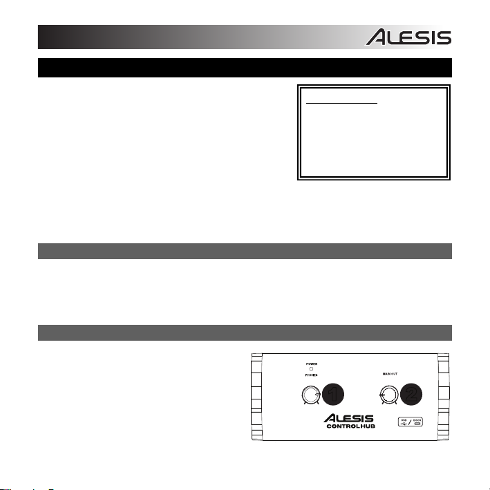
Front Panel
1. Headphone Volume – Adjusts the signal
level of the HEADPHONE OUTPUT.
2. Main Output Volume – Adjusts the signal
level of the MAIN OUTPUTS.
3
BOX CONTENTS
Control Hub
Ignite Software (download)
USB Cable
User Guide
Safety & Warranty Manual
1 2
Page 4
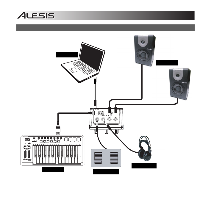
Connection Diagram
COMPUTER*
KEYBOARD*
FOOTSWITCH*
HEADPHONES*
SPEAKERS*
* Sold
Separately
4
Page 5
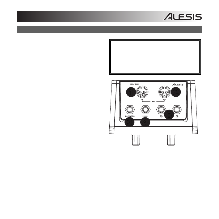
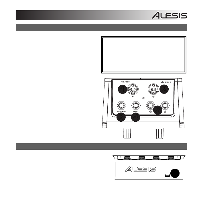
Top Panel
1. MIDI In – Use a standard five-pin MIDI cable
to connect this input to the MIDI OUT of an
external MIDI device.
2. MIDI Out – Use a standard five-pin MIDI
cable to connect this output to the MIDI IN of
an external MIDI device.
3. Footswitch – Use a standard 1/4" TS, or
1/4" TRS dual-button footswitch to send
MIDI messages to the computer. See the
Footswitch Control section for more details.
4. Headphone Output – Connect your 1/4"
headphones to this output.
5. Main L/R Outputs – Use standard 1/4"
cables to connect these outputs to a mixer,
monitor speakers, or amplifier.
Note: Be sure your MIDI sequencing software
is set up to receive MIDI signals from Control
Hub. This can usually be done in your
software's "Preferences" or "Device Setup."
Please consult your software manual for more
information.
1
2
5
3
4
5
Page 6
1
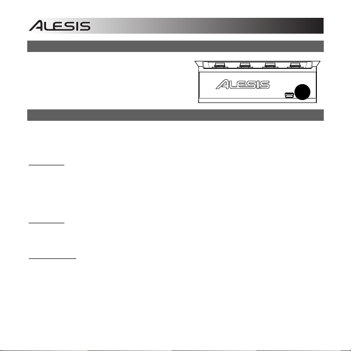
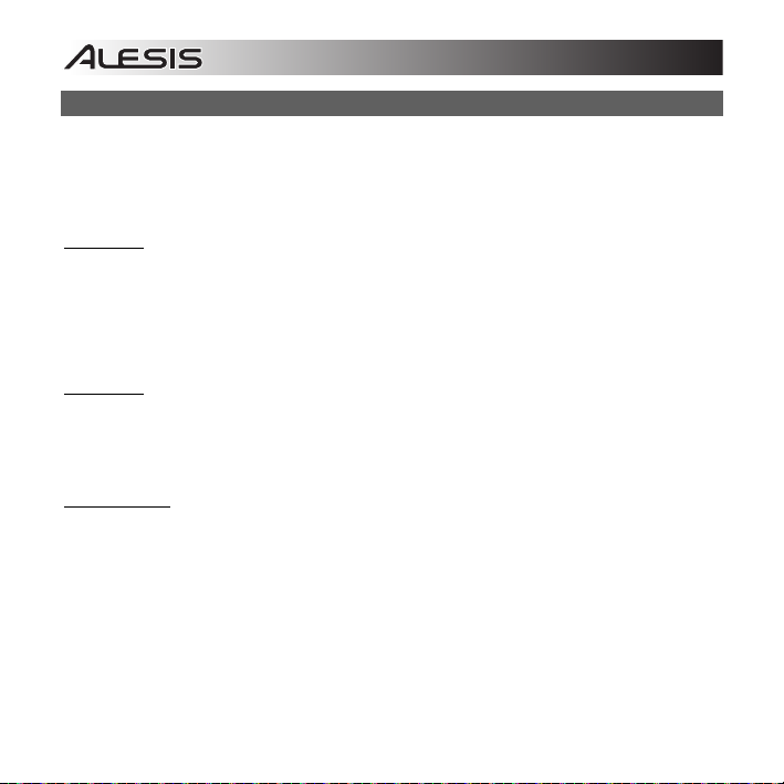
Rear Panel
1. USB Port – Use the included USB cable to
connect
Control Hub to your computer. This
connection will power Control Hub.
Audio Setup
Control Hub is a class-compliant device that can be used with any digital audio workstation or MIDI
sequencing software that supports USB class-compliant devices. To enable Control Hub to monitor
audio from your computer, follow the instructions below for your computer's operating system:
Windows 8:
1. Use the included USB cable to connect the Control Hub to your computer.
2. Go to the Start Menu, click the lower-left corner of the screen to go to the Desktop.
3. In the Taskbar, locate the Volume Control "Speaker" icon. Right-click the speaker and select
Playback Devices.
4. In the Windows Sound control panel select the Playback tab and select Control Hub as the
default device.
Windows 7:
1. Use the included USB cable to connect the Control Hub to your computer.
2. Go to Start Menu Control Panel Hardware and Sound Sound.
3. Click the Playback tab and select Control Hub as the default device.
Windows Vista:
1. Use the included USB cable to connect the Control Hub to your computer.
2. Go to Start Menu Control Panel Sound. (If you don't see Sound, select Switch to
Classic View, and the Sound Control Panel should become available.)
3. Click the Playback tab and select Control Hub as the default device.
6
Page 7
Windows XP:
1. Use the included USB cable to connect the Control Hub to your computer.
2. Go to Start Menu Control Panel Sounds and Audio Devices.
3. Click the Audio tab.
4. Under Sound Playback, select Control Hub as the default device.
Mac OS X:
1. Use the included USB cable to connect the Control Hub to your computer. Then go to
Applications Utilities Audio MIDI Setup.
2. In the Audio Devices tab select the System Settings menu.
3. In the Audio Devices Menu, right click on "Control Hub".
4. Select "Use this device for sound output".
Audio Latency
“Latency” is the time it takes for your computer’s
soundcard to process incoming data and output a
sound. The lower your latency is, the faster your
computer will respond to commands and output
sound.
A good example of latency is the time it takes for the
computer to output a sound when a key is struck on
a MIDI keyboard connected to it. In this situation, it
is important to have low latency so that there is no
audible delay between the time the key is struck,
and when the note is heard.
If you experience a significant delay between the time you play and the time that the computer outputs
audio, we recommend going into your software’s “Preferences” settings to make sure that your
soundcard’s latency (or buffer) is set to a low number – ideally lower than 15-20ms.
If you experience too much latency after adjusting your software latency settings, we recommend the
free ASIO4ALL (Audio Stream Input/Output) driver for PC at asio4all.com. ASIO drivers generally
perform better than the computer’s built-in drivers and with lower latency since they create a more
efficient communication between audio devices and software.
If you experience too much latency after
adjusting your software latency settings, we
recommend the free ASIO4ALL (Audio
Stream Input/Output) driver for PC at
asio4all.com. ASIO drivers generally
perform better and with lower latency since
they create a more efficient communication
between audio devices and software.
7
Page 8

1. Download and Install the free ASIO4ALL driver from asio4all.com. This will allow for low latency
performance.
2. Double click the installer file (.exe). Follow the on-screen prompts to install the included low
latency ASIO4ALL driver.
Footswitch Control
Connect a single- or dual-button footswitch to Control Hub to send CC messages that can be assigned
in your software.*
If you are using a single-button footswitch, pressing the footswitch for the first time sends a value of
"127" for CC #14 over Channel 1. Pressing the footswitch for the second time sends a value of "0" for
CC #14 over Channel 1.
If you are using the first button of a dual-button footswitch, pressing the first button for the first time
sends a value of "127" for CC #15 over Channel 1. Pressing the first button for the second time sends
a value of "0" for CC #15 over Channel 1. If you are using the second button of a dual-button
footswitch, pressing the second button for the first time sends a value of "127" for CC #14 over
Channel 1. Pressing the second button for the second time sends a value of "0" for CC #14 over
Channel 1.
*Please consult your software's manual for more information on assigning these CC messages.
8
Page 9
Guía del usuario (Español)
1. Asegúrese de que estén presentes todos los elementos
enumerados en Contenido de la caja.
2. LEA EL FOLLETO DE INSTRUCCIONES DE
SEGURIDAD ANTES DE UTILIZAR EL PRODUCTO.
3. Coloque el producto en un lugar adecuado para su
funcionamiento.
4. Asegúrese de usar cables de audio blindados de alta
calidad y alejados de las fuentes de interferencia
electromagnética.
Para registrar el producto, visite alesis.com.
Fara obtener la información más reciente acerca de este producto (requisitos de sistema, información
de compatibilidad, etc.), visite alesis.com/control-hub.
Para soporte adicional del producto, visite alesis.com/support.
Software incluido
• Ignite: Recomendamos descargar Ignite, una herramienta de creación musical diseñada por AIR
Music Technology para que sea la manera más fácil de capturar, crear y compartir ideas
musicales. Ignite funciona bien en forma autónoma o como acompañante de composición de las
capacidades de producción de su DAW.
Visite airmusictech.com/getignite para descargar e instalar su ejemplar de Ignite.
CONTENIDO DE LA CAJA
Control Hub
Software Ignite (descargar)
Cable USB
Guía del usuario
Manual sobre la seguridad y
garantía
9
Page 10

A
A
Panel frontal
1. Volumen de auriculares – Permite ajustar
el volumen de señal de la salida PHONES
(Auriculares).
2. Volumen de la salida principal – Permite
ajustar el volumen de señal de la salida
MAIN OUTPUT (Principal).
1 2
Diagrama de conexión
COMPUTADORA*
TECLADO*
LTAVOCES*
URICULARES*
INTERRUPTOR
10
*Se vende por
separado
Page 11
1
Panel superior
1. Entrada MIDI – Use un cable MIDI estándar
de cinco pines para conectar esta entrada a
la SALIDA MIDI de un dispositivo MIDI
externo.
2. Salida MIDI – Use un cable MIDI estándar
de cinco pines para conectar esta salida a la
ENTRADA MIDI de un dispositivo MIDI
externo.
3. Interruptor de pedal – Use un interruptor
de pedal estándar TS de 1/4 pulg. o TRS de
1/4 pulg. de dos botones para enviar
mensajes MIDI a la computadora. Para más
detalles, consulte la sección Control del
interruptor de pedal.
4. Salida para auriculares – Conecte sus
auriculares de 1/4” a esta salida.
5. Salidas principales izq./der. – Use cables
estándar de 1/4 pulg. para conectar estas
salidas a un mezclador, altavoces monitores
o un amplificador.
Panel trasero
1. Puerto USB – Use el cable USB incluido para
conectar el
conexión alimenta el Control Hub.
Control Hub a su computadora. Esta
11
Nota: Asegúrese de que su software de
secuencia MIDI esté configurado para recibir
señales MIDI desde el Control Hub. Esto se
puede hacer habitualmente en “Preferences”
(Preferencias) o “Device Setup” (Configuración
de dispositivos) del software. Para más
información, consulte el manual del software.
1
2
5
3
4
Page 12
Ajuste del audio
El Control Hub es un dispositivo que cumple especificaciones de clase y que se puede usar con
cualquier estación de trabajo o software de secuencia MIDI compatible con los dispositivos que
cumplen la clase USB. Para habilitar el Control Hub a fin de monitorear el audio desde su
computadora, siga las instrucciones incluidas a continuación para el sistema operativo de su
computadora:
Windows 8:
1. Use el cable USB incluido para conectar el Control Hub a su computadora.
2. Vaya al menú Start (Inicio), haga clic en la esquina inferior izquierda de la pantalla para entrar al
escritorio.
3. En la barra de tareas, localice el icono del control de volumen del altavoz. Haga clic derecho en
el altavoz y seleccione Playback Devices (Dispositivos de reproducción).
4. En el panel de control Windows Sound (Sonido de Windows) seleccione la pestaña Playback
(Reproducción) y seleccione Control Hub como dispositivo predeterminado.
Windows 7:
1. Use el cable USB incluido para conectar el Control Hub a su computadora.
2. Vaya al menú Start Control Panel Hardware and Sound Sound (Inicio > Panel de
Control > Hardware y sonido > Sonido).
3. Haga clic en la pestaña Playback (Reproducción) y seleccione Control Hub como dispositivo
predeterminado.
Windows Vista:
1. Use el cable USB incluido para conectar el Control Hub a su computadora.
2. Vaya al menú Start Control Panel Sound (Inicio > Panel de control > Sonido). (Si no ve
Sound, seleccione Switch to Classic View (Cambiar a vista clásica). Debe aparecer el panel
de control Sound Control Panel.)
3. Haga clic en la pestaña Playback (Reproducción) y seleccione Control Hub como dispositivo
predeterminado.
12
Page 13

Windows XP:
1. Use el cable USB incluido para conectar el Control Hub a su computadora.
2. Vaya al menú Start Control Panel Sounds and Audio Devices (Inicio > Panel de control
> Dispositivos de sonido y audio).
3. Haga clic en la pestaña Audio.
4. Bajo Sound Playback (Reproducción de sonido), seleccione Control Hub como dispositivo
predeterminado.
Mac OS X:
1. Use el cable USB incluido para conectar el Control Hub a su computadora. A continuación, vaya
a Applications Utilities Audio MIDI Setup (Aplicaciones > Utilidades > Configuración
MIDI de audio).
2. En la pestaña Audio Devices (Dispositivos de audio) seleccione el menú System Settings
(Configuración del sistema).
3. En el menú Audio Devices, haga clic derecho en "Control Hub".
4. Seleccione "Use this device for sound output" (Usar este dispositivo para salida de sonido).
Latencia de audio
“Latencia” es el tiempo que demora la tarjeta de
sonido de la computadora para procesar los datos
entrantes y producir un sonido de salida. Cuando
más baja es la latencia, más rápido responde su
computadora a los comandos para producir sonido.
Un buen ejemplo de latencia es el tiempo que
demora la computadora en emitir un sonido cuando
se pulsa una tecla en un teclado MIDI conectado a
ella. En esta situación, es importante tener baja
latencia de modo que no exista un retardo audible
entre el momento que se pulsa la tecla y el
momento en que se escucha la nota.
Si experimenta un retardo significativo entre el momento en que usted toca y el momento en que la
computadora produce audio, recomendamos entrar en los parámetros “Preferences” (Preferencias) de
su software para asegurarse de que la latencia (o búfer) de la tarjeta de sonido esté ajustada a un
número bajo —idealmente inferior a 15-20 ms.
Si experimenta demasiada latencia
después de ajustar los parámetros de
latencia de su computadora,
recomendamos el driver ASIO4ALL
(Entrada/salida de streaming de audio) para
PC de asio4all.com. En general, los
drivers ASIO funcionan mejor y con menor
latencia, dado que crean una comunicación
más eficiente entre los dispositivos de
audio y el software.
13
Page 14

Si experimenta demasiada latencia después de ajustar los parámetros de latencia de su computadora,
recomendamos el driver ASIO4ALL (Entrada/salida de streaming de audio) para PC de asio4all.com.
En general, los drivers ASIO funcionan mejor que los drivers integrados a la computadora y con menor
latencia, dado que crean una comunicación más eficiente entre los dispositivos de audio y el software.
1. Descargue e instale el driver gratuito ASIO4ALL desde asio4all.com. Esto permitirá un
funcionamiento con baja latencia.
2. Haga doble clic en el archivo instalador (.exe). Siga las indicaciones de la pantalla para instalar el
driver ASIO4ALL de baja latencia incluido.
Control de interruptor de pedal
Conecte un interruptor de pedal de uno o dos botones a Control Hub para enviar mensajes CC que se
puedan asignar en su software*.
Si está usando un interruptor de pedal de un solo botón, al presionar el interruptor por primera vez,
envía un valor de "127" para CC #14 por el Canal 1. Al presionarlo por segunda vez, envía un valor de
"0" para CC #14 por el Canal 1.
Si está usando el primer botón de un interruptor de pedal de dos botones, al presionar el primer botón
por primera vez, envía un valor de "127" para CC #15 por el Canal 1. Al presionar el primer botón por
segunda vez, envía un valor de "0" para CC #15 por el Canal 1. Si está usando el segundo botón de
un interruptor de pedal de dos botones, al presionar el segundo botón por primera vez envía un valor
de "127" para CC #14 por el Canal 1. Al presionar el segundo botón por segunda vez envía un valor
de "0" para CC #14 por el Canal 1.
*Para más información acerca de la asignación de estos mensajes CC, consulte el manual de su software.
14
Page 15

Guide d’utilisation (Français)
1. Assurez-vous que tous les articles énumérés dans la
section Contenu de la boîte de ce guide sont inclus dans
la boîte.
2. VEUILLEZ LIRE LE LIVRET DES CONSIGNES DE
SÉCURITÉ AVANT D'UTILISER LE PRODUIT.
3. Placez le produit dans un endroit approprié à son
utilisation.
4. Veuillez vous assurer que les câbles audio blindés de
qualité supérieure sont utilisés loin des sources
d’interférences électromagnétiques.
Pour l'enregistrement du produit, veuillez visiter alesis.com.
Pour les toutes dernières informations concernant la configuration système, la compatibilité et
l’enregistrement du produit, veuillez visiter alesis.com/control-hub.
Pour de l’assistance supplémentaire, veuillez visiter alesis.com/support.
Logiciel inclus
• Ignite : Nous vous recommandons de télécharger le logiciel Ignite, un outil de création musicale
conçu par AIR Music Technology afin de faciliter la saisie, le peaufinage et le partage des idées
musicales. Il peut être utilisé seul ou en guise de complément d’écriture à votre logiciel
audionumérique.
Veuillez visiter airmusictech.com/getignite pour télécharger et installer votre copie d’Ignite.
CONTENU DE LA BOÎTE
Control Hub
Logiciel Ignite (à télécharger)
Câble USB
Guide d’utilisation
Consignes de sécurité et
informations sur la garantie
15
Page 16

Panneau avant
1. PHONES – Ce bouton rotatif ajuste les
niveaux de la sortie du casque d'écoute.
2. MAIN OUT – Ce bouton rotatif permet
d'ajuster le niveau du volume des sorties
principales.
1 2
Schéma de connexion
ORDINATEUR*
CLAVIER*
COMMANDE AU PIED*
16
HAUT-PARLEURS*
*Vendus
séparément
CASQUE D’ÉCOUTE*
Page 17

1
Panneau supérieur
1. MIDI IN – Utilisez un câble MIDI à cinq
broches afin de brancher cette entrée à la
sortie MIDI OUT d’un appareil MIDI externe.
2. MIDI OUT – Vous pouvez brancher un câble
MIDI à cinq broches à cette sortie et à
l’entrée MIDI IN d’un appareil MIDI externe.
3. FOOTSWITCH – Utilisez un câble pour
pédale TS standard de 6,35 mm (1/4 po) ou
TRS 6,35 mm (1/4 po) à commutateur
double pour transmettre des messages MIDI
à l'ordinateur. Reportez-vous à la section de
Commande au pied pour plus de détails.
4. PHONES – Un casque d'écoute 6,35 mm
(1/4 po) peut être branché à cette sortie.
5. Sorties principales gauche et droite
(L/R) – Utilisez des câbles standards
6,35 mm (1/4 po) afin de brancher ces
sorties à une console de mixage, des
enceintes de cabine ou à un amplificateur.
Panneau arrière
1. Port USB – Utilisez le câble USB compris afin de
brancher le Control Hub à votre ordinateur. Cette
connexion permet d'alimenter le Control Hub.
Remarque : Veillez à ce que votre logiciel de
séquençage MIDI soit configuré pour recevoir
des signaux MIDI du Control Hub. Vérifiez dans
les paramètres « Préférences » ou « Installation
du périphérique ». Pour de plus amples
informations, veuillez consulter le guide
d’utilisation du logiciel.
1
2
5
3
4
17
Page 18

Configuration audio
Le Control Hub est un périphérique nativement compatible est peut donc être utilisé avec tout poste
audio numérique ou logiciel de séquençage MIDI qui prend en charge les périphériques audio USB
nativement compatible. Afin que le Control Hub puisse contrôler le signal audio de votre ordinateur,
veuillez suivre les directives ci-dessous selon le système d’exploitation de votre ordinateur :
Windows 8 :
1. Utilisez le câble USB inclus pour brancher le Control Hub à un ordinateur.
2. Dans le menu Démarrer, cliquez sur le coin inférieur gauche de l'écran pour afficher le bureau.
3. Dans la barre des tâches, recherchez l’icône de la commande de volume « haut-parleur ».
Faites un clic droit sur l’icône du haut-parleur et sélectionnez Périphériques de lecture.
4. Dans le panneau de configuration Son, sélectionnez l'onglet Lecture, puis sélectionnez Control
Hub comme le périphérique par défaut.
Windows 7 :
1. Utilisez le câble USB inclus pour brancher le Control Hub à un ordinateur.
2. Cliquez sur Démarrer Panneau de configuration Matériel et audio Son.
3. Cliquez sur l’onglet Lecture et sélectionnez Control Hub comme périphérique par défaut.
Windows Vista :
1. Utilisez le câble USB inclus pour brancher le Control Hub à un ordinateur.
2. Cliquez sur DémarrerPanneau de configuration Son. (Si vous ne voyez pas Son,
sélectionnez Basculer vers l’affichage classique et le panneau de configuration Son devrait
s'afficher.)
3. Cliquez sur l’onglet Lecture et sélectionnez Control Hub comme périphérique par défaut.
Windows XP :
1. Utilisez le câble USB inclus pour brancher le Control Hub à un ordinateur.
2. Cliquez sur Démarrer Panneau de configuration Sons et périphériques audio.
3. Cliquez sur l’onglet Audio.
4. Sous Lecture audio, sélectionnez Control Hub comme périphérique par défaut.
18
Page 19

Mac OS X :
1. Utilisez le câble USB inclus pour brancher le Control Hub à un ordinateur. Cliquez ensuite sur
Applications Utilitaires Configuration audio et MIDI.
2. Dans l'onglet Sons et périphériques audio sélectionner le menu Paramètres système.
3. Sous Périphériques audio, faites un clic droit sur « Control Hub ».
4. Sélectionnez « Utiliser ce périphérique pour la sortie audio ».
Latence audio
La latence est le temps que met l’ordinateur à traiter
les données entrantes et à produire un son. Plus
faible est la latence, plus l'ordinateur répond
rapidement aux commandes et émet un signal.
Le temps nécessaire à l'ordinateur pour émettre un
signal sonore après qu'une touche sur un clavier
MIDI branché soit enfoncée est un bon exemple de
latence. Dans ce cas, il est important d'avoir une
faible latence, afin qu'il n'y ait pas de retard audible
entre le moment où la touche est enfoncée et la
note est entendue.
Si vous éprouvez un délai entre le moment que vous jouez et que l’ordinateur reproduise le son, nous
vous recommandons d'ajuster les réglages « Préférences » du logiciel en vous assurant que les
paramètres de latence de votre carte son (ou mémoire tampon) soient à un réglage bas, idéalement
plus bas que 15-20 ms.
S'il y a toujours trop de latence après avoir modifié les paramètres de latence du logiciel, téléchargez
gratuitement le pilote ASIO4ALL (Audio Stream Input/Output) pour PC de asio4all.com. Les pilotes
ASIO fonctionnent généralement mieux et avec une plus faible latence que les pilotes intégrés des
ordinateurs, car ils créent une communication plus efficace entre les logiciels et périphériques audio.
1. Téléchargez et installez gratuitement le pilote ASIO4ALL de asio4all.com. Cela permettra
d’obtenir une performance à faible latence.
2. Double-cliquez sur le fichier d'installation (.exe). Suivez les instructions à l’écran pour installer le
pilote ASIO4ALL à faible latence.
S'il y a toujours trop de latence après avoir
modifié les paramètres de latence du
logiciel, téléchargez gratuitement le pilote
ASIO4ALL (Audio Stream Input/Output)
pour PC de asio4all.com. Les pilotes ASIO
fonctionnent généralement mieux et avec
une plus faible latence, car ils créent une
communication plus efficace entre les
logiciels et périphériques audio.
19
Page 20

Commande au pied
Branchez une commande au pied simple ou double au Control Hub afin de transmettre des messages
CC qui peuvent être assignés à une fonction de votre logiciel.*
Si vous utilisez une commande au pied simple, la première fois que vous appuyez un message ayant
une valeur de « 127 » pour CC #14 est envoyé sur le canal 1. La deuxième fois que vous appuyez, un
message ayant une valeur de « 0 » pour CC #14 est envoyé sur le canal 1.
Si vous utilisez une commande au pied double, la première fois que vous appuyez sur le premier
bouton un message ayant une valeur de « 127 » pour CC #15 est envoyé sur le canal 1. La deuxième
fois que vous appuyez sur le premier bouton, un message ayant une valeur de « 0 » pour CC #15 est
envoyé sur le canal 1. Si vous utilisez le deuxième bouton d’une commande au pied double, la
première fois que vous appuyez sur le deuxième bouton un message ayant une valeur de « 127 » pour
CC #14 est envoyé sur le canal 1. La deuxième fois que vous appuyez sur le deuxième bouton, un
message ayant une valeur de « 0 » pour CC #14 est envoyé sur le canal 1.
* Veuillez consulter le guide d'utilisation de votre logiciel pour plus d'informations sur l'affectation de ces messages CC.
20
Page 21

Guida rapida (Italiano)
1. Assicurarsi che tutti gli elementi elencati nella parte
“Contenuti della confezione” siano inclusi.
2. LEGGERE ATTENTAMENTE IL LIBRETTO DELLE
ISTRUZIONI DI SICUREZZA PRIMA DI UTILIZZARE IL
PRODOTTO.
3. Collocare il prodotto in una posizione adeguata all’uso.
4. Assicurarsi di utilizzare cavi audio di alta qualità
schermati lontano da fonti di interferenze
elettromagnetiche.
Per la registrazione del prodotto, recarsi alla pagina
alesis.com.
Per le ultime informazioni in merito a questo prodotto (requisiti di sistema, informazioni sulla
compatibilità, ecc.), recarsi alla pagina alesis.com/control-hub.
Per ulteriore assistenza sul prodotto, recarsi alla pagina alesis.com/support.
Software incluso
• Ignite: consigliamo di scaricare Ignite, uno strumento di creazione musicale concepito da AIR
Music Technology per essere il modo più facile di captare, costruire e condividere idee musicali.
Ignite funziona bene da solo o affiancato alle capacità produttive del vostro DAW.
Recarsi alla pagina airmusictech.com/getignite per scaricare e installare la propria copia di
Ignite.
CONTENUTI DELLA
CONFEZIONE
Control Hub
Software Ignite (download)
Cavo USB
Guida per l'uso
Istruzioni di sicurezza e
garanzia
21
Page 22

A
Pannello anteriore
1. Volume cuffie – Regola il livello del volume
dell’USCITA CUFFIE.
2. Volume uscita principale (Main) – Regola il
livello del volume dell’USCITA MAIN
(principale).
1 2
Schema dei collegamenti
COMPUTER*
TASTIERA*
INTERRUTTORE A
PEDALE*
22
LTOPARLANTI*
CUFFIE*
*Venduti
separatamente
Page 23

1
Pannello superiore
1. MIDI In (ingresso MIDI) – Servirsi di un
cavo MIDI standard a cinque poli per
collegare questo ingresso all’uscita MIDI di
un dispositivo MIDI esterno.
2. MIDI Out (uscita MIDI) – Servirsi di un cavo
MIDI standard a cinque poli per collegare
questa uscita all’ingresso MIDI di un
dispositivo MIDI esterno.
3. Interruttore a pedale – Servirsi di un
interruttore a pedale standard TS da 1/4" TS
o TRS da 1/4" TRS a doppio tasto per
inviare messaggi MIDI al computer. Per
maggiori informazioni, si veda il paragrafo
Comando con interruttore a pedale.
4. Uscita cuffie – Collegare a questa uscita le
proprie cuffie da 1/4”.
5. Uscite
Main L/R (destra/sinistra) –
Servirsi di cavi standard da 1/4" per
collegare queste uscite a un mixer,
altoparlanti a monitor o amplificatori.
Pannello posteriore
1. Porta USB – Servirsi del cavo USB in dotazione
per collegare il Control Hub al computer. Questo
collegamento alimenta il Control Hub.
23
Nota bene: assicurarsi che il software di
sequencing sia impostato per ricevere segnali
MIDI del Control Hub. Questo può essere
solitamente fatto a livello delle “Preferenze” del
software o della “Configurazione periferica”. Per
maggiori informazioni, consultate il manuale del
vostro software.
1
2
5
3
4
Page 24

Configurazione audio
L'hub di controllo è un dispositivo compatibile che può essere utilizzato con qualsiasi workstation audio
digitale o software di sequencing MIDI che supporta dispositivi conformi USB. Per abilitare il Control
Hub per monitorare l'audio del computer, seguire le istruzioni di cui sotto per il sistema operativo del
computer di cui si dispone:
Windows 8:
1. Servirsi del cavo USB in dotazione per collegare il Control Hub al computer.
2. Nel menu Start, cliccare sull'angolo inferiore sinistro dello schermo per passare al Desktop.
3. Nella Barra delle applicazioni, individuare l'icona "Speaker" di controllo del Volume. Fare click col
tasto destro del mouse e selezionare Dispositivi di riproduzione.
4. Nel pannello di controllo Audio di Windows selezionare la scheda Riproduzione e selezionare
Control Hub come dispositivo predefinito.
Windows 7:
1. Servirsi del cavo USB in dotazione per collegare il Control Hub al computer.
2. Recarsi su Start Pannello di controllo Hardware e suoni Audio.
3. Cliccare sulla linguetta Riproduzione e selezionare Control Hub come periferica predefinita.
Windows Vista:
1. Servirsi del cavo USB in dotazione per collegare il Control Hub al computer.
2. Recarsi su Start Pannello di controllo Audio. (Se non viene visualizzato Audio,
selezionare “Visualizzazione classica” ed il Pannello di controllo Audio dovrebbe diventare
disponibile.)
3. Cliccare sulla linguetta Riproduzione e selezionare Control Hub come periferica predefinita.
Windows XP:
1. Servirsi del cavo USB in dotazione per collegare il Control Hub al computer.
2. Recarsi su Start Pannello di controllo Suoni e periferiche audio.
3. Fare clic sulla scheda Audio.
4. Cliccare sulla scheda Riproduzione suoni e selezionare il Control Hub come periferica
predefinita.
24
Page 25

Mac OS X:
1. Servirsi del cavo USB in dotazione per collegare il Control Hub al computer. Quindi recarsi su
Applicazioni Utilità Audio MIDI Setup.
2. Nella scheda Periferiche Audio selezionare il menù Configurazioni di sistema.
3. Nel menù Periferiche audio, fare clic con tasto destro del mouse su "Hub di controllo".
4. Selezionare "utilizzare questo dispositivo come uscita audio".
Latenza audio
La “Latenza” è il tempo che occorre alla scheda audio
del vostro computer per elaborare i dati in arrivo ed
emettere un suono. Più la latenza è bassa e più
rapidamente il computer risponderà ai comandi
emettendo suoni.
Un buon esempio di latenza è il tempo che occorre al
computer per emettere un suono quando viene suonata
una nota su una tastiera MIDI collegata. In questa
situazione è importante avere una bassa latenza in
modo che non ci sia un ritardo udibile tra il momento in
cui viene suonata la nota e quello in cui la nota viene
udita.
Qualora si dovesse verificare un notevole ritardo tra il tempo in cui si suona e quello in cui il computer emette
audio, si consiglia di recarsi alla scheda “Preferiti” delle configurazioni del software per assicurarsi che la
latenza della scheda audio (o buffer) sia impostata su un livello basso: idealmente, inferiore a 15-20ms.
Qualora si dovesse ancora verificare un’eccessiva latenza dopo aver sistemato la configurazione della latenza
a livello del vostro software, scaricate il driver gratuito ASIO4ALL (Audio Stream Input/Output) per PC alla
pagina asio4all.com. Solitamente, i driver ASIO hanno prestazioni migliori rispetto ai driver incorporati dei
computer e una minore latenza in quanto creano una comunicazione più efficiente tra dispositivi audio e
software.
1. Scaricare e installare il driver gratuito ASIO4ALL dalla pagina asio4all.com. Questo garantirà prestazioni
a bassa latenza.
2. Fare doppio clic sul file di installazione (.exe). Seguire le istruzioni su schermo per installare i driver
ASIO4ALL a bassa latenza in dotazione.
Qualora si dovesse ancora verificare
un’eccessiva latenza dopo aver sistemato
la configurazione della latenza a livello del
vostro software, scaricate il driver gratuito
ASIO4ALL (Audio Stream Input/Output) per
PC alla pagina asio4all.com. Solitamente, i
driver ASIO hanno prestazioni migliori e con
una minore latenza in quanto creano una
comunicazione più efficiente tra dispositivi
audio e software.
25
Page 26

Controllo interruttore a pedale
Collegare un tasto a pedale singolo o doppio al Control Hub per inviare messaggi CC assegnabili nel
software.*
Se si utilizza un interruttore a pedale singolo, una prima pressione dell'interruttore invia un valore di
"127" per CC #14 sul Canale 1. Premendo l'interruttore una seconda volta si invia un valore di "0" per
CC #14 sul Canale 1.
Se si utilizza il primo tasto di un interruttore a pedale doppio, una prima pressione dell'interruttore invia
un valore di "127" per CC #15 sul Canale 1. Premendo il primo tasto per la seconda volta si invia un
valore di "0" per CC #15 sul Canale 1. Se si utilizza il secondo tasto di un interruttore a pedale doppio,
la prima pressione del secondo interruttore invia un valore di "127" per CC #14 sul Canale 1.
Premendo il secondo tasto per la seconda volta si invia un valore di "0" per CC #14 sul Canale 1.
*Consultare il manuale del software per maggiori informazioni sull'assegnazione di questi messaggi CC.
26
Page 27

Benutzerhandbuch (Deutsch)
1. Stellen Sie sicher, dass alle im Lieferumfang
aufgelisteten Teile in der Verpackung enthalten sind.
2. LESEN SIE DIE SICHERHEITSHINWEISE, BEVOR SIE
DAS PRODUKT VERWENDEN.
3. Stellen Sie das Gerät an einen für den Betrieb
geeigneten Standort.
4. Stellen Sie sicher, dass die hochwertigen, geschirmten
Audiokabel nicht in der Nähe von Quellen verwendet
werden, die elektromagnetische Interferenzen
verursachen.
Besuchen Sie alesis.com, um Ihr Produkt zu registrieren.
Die neuesten Informationen zu diesem Produkt (Systemanforderungen, Informationen zur
Kompatibilität etc.) erhalten Sie auf alesis.com/control-hub.
Für weitere Unterstützung besuchen Sie alesis.com/support.
Mitgelieferte Software
• Ignite: Wir empfehlen Ihnen das Musikproduktions-Tool Ignite herunterzuladen: Ignite wurde von
AIR Music Technology entwickelt, um musikalische Ideen möglichst einfach zu erfassen, zu
bearbeiten und zu veröffentlichen. Ignite kann alleine oder als zusätzliches Tool mit Ihrer DAW
eingesetzt werden.
Besuchen Sie airmusictech.com/getignite, um Ihre Kopie von Ignite herunterzuladen und zu
installieren.
LIEFERUMFANG
Control Hub
Ignite Software (Download)
USB-Kabel
Benutzerhandbuch
Sicherheitshinweise und
Garantieinformationen
27
Page 28

Vorderseite
1. Kopfhörerlautstärke - Regelt die
Lautstärke des KOPFHÖRERAUSGANGS.
2. Hauptausgangspegel - Regelt den
Signalpegel der HAUPTAUSGÄNGE.
1 2
Anschlussdiagramm
COMPUTER*
KEYBOARD*
LAUTSPRECHER*
* Separat erhältlich
KOPFHÖRER*
FUSS-SCHALTER*
28
Page 29

1
Oberseite
1. MIDI In - Verwenden Sie ein
handelsübliches MIDI-Kabel mit 5 Pins, um
diesen Eingang mit dem MIDI OUT eines
externen MIDI-Geräts zu verbinden.
2. MIDI Out - Verwenden Sie ein
handelsübliches MIDI-Kabel mit 5 Pins, um
diesen Ausgang mit dem MIDI IN eines
externen MIDI-Geräts zu verbinden.
3. Fußschalter - Verwenden Sie einen
handelsüblichen 1/4" TS oder 1/4" TRS
Zwei-Tasten-Fußschalter, um MIDINachrichten an den Computer zu schicken.
Siehe Abschnitt Fußschaltersteuerung für
weitere Details.
4. Kopfhörerausgang - Schließen Sie 1/4"-
Kopfhörer an diesen Ausgang an.
5. L/R Hauptausgänge - Verwenden Sie
handelsübliche 1/4"-Kabel, um diese
Ausgänge an einen Mixer, Monitore oder ein
Verstärkersystem anzuschließen.
Rückseite
1. USB Port - Schließen Sie den Control Hub
dem mitgelieferten USB-Kabel an Ihren Computer
an. Diese Verbindung wird den Control Hub mit
Strom versorgen.
Hinweis: Vergewissern Sie sich, dass Ihre
MIDI-Sequenzer-Software so eingerichtet ist,
dass MIDI-Signale vom Control Hub empfangen
werden können. Dies kann üblicherweise in den
"Einstellungen" oder im "Geräte-Setup" Ihrer
Software festgelegt werden. Weitere
Informationen finden Sie in Ihrem SoftwareHandbuch.
1
2
5
3
4
mit
29
Page 30

Audio-Setup
Der Control Hub ist ein klassenkompatibles Gerät, das mit jeder beliebigen digitalen Audio-Workstation
und jeder MIDI-Sequenzer-Software verwendet werden kann, die USB-klassenkompatible Geräte
unterstützt. Befolgen Sie die nachstehenden Anweisungen für Ihr jeweiliges Betriebssystem, um dem
Control Hub das Monitoring der Audiosignale Ihres Computers zu ermöglichen:
Windows 8:
1. Schließen Sie den Control Hub mit dem mitgelieferten USB-Kabel an Ihren Computer an.
2. Im Startmenü klicken Sie in die linke untere Ecke des Bildschirms, um zum Desktop zu
gelangen.
3. In der Taskleiste suchen Sie das Lautsprechersymbol für die Lautstärke. Klicken Sie mit der
rechten Maustaste auf den Lautsprecher und wählen Wiedergabegeräte.
4. In der Windows-Systemsteuerung für Sound wählen Sie die Registerkarte Wiedergabe und
wählen Control Hub als Standard-Gerät aus.
Windows 7:
1. Schließen Sie den Control Hub mit dem mitgelieferten USB-Kabel an Ihren Computer an.
2. Wählen Sie Startmenü Systemsteuerung Hardware und Sound Sound.
3. Klicken Sie auf die Registerkarte Wiedergabe und wählen Control Hub als Standardgerät aus.
Windows Vista:
1. Schließen Sie den Control Hub mit dem mitgelieferten USB-Kabel an Ihren Computer an.
2. Wählen Sie Startmenü Systemsteuerung Sound. (Wenn Sie Sound nicht sehen können,
wählen Sie Auf klassische Ansicht wechseln. Das Fenster Sound-Eigenschaften sollte nun
verfügbar sein.)
3. Klicken Sie auf die Registerkarte Wiedergabe und wählen den Control Hub als Standardgerät
aus.
Windows XP:
1. Schließen Sie den Control Hub mit dem mitgelieferten USB-Kabel an Ihren Computer an.
2. Wählen Sie Startmenü Systemsteuerung Sounds und Audiogeräte.
3. Klicken Sie auf die Registerkarte Audio.
4. Unter Soundwiedergabe wählen Sie Control Hub als Standardgerät.
30
Page 31
Mac OS X:
1. Schließen Sie den Control Hub mit dem mitgelieferten USB-Kabel an Ihren Computer an.
Wählen Sie anschließend Anwendungen Dienstprogramme Audio-MIDI-Setup.
2. In der Registerkarte Audiogeräte wählen Sie das Menü Systemeinstellungen.
3. Im Menü Audiogeräte klicken Sie mit der rechten Maustaste auf "Control Hub".
4. Wählen Sie "Dieses Gerät als Ausgabegerät verwenden".
Audiolatenz
"Latenz" ist die Zeit, die die Soundkarte des
Computers benötigt, um eingehende Daten zu
verarbeiten und ein Audiosignal auszugeben. Je
niedriger die Latenz ist, desto schneller wird Ihr
Computer auf Befehle reagieren und Audiosignale
ausgeben.
Ein gutes Beispiel für Latenz ist jene Zeitspanne,
die der Computer benötigt, um einen Ton
auszugeben, nachdem eine Taste auf einem
angeschlossenen MIDI-Keyboard angeschlagen
wurde. In diesem Fall ist es wichtig, die Latenzzeit
möglichst kurz zu halten, damit es zu keinen
hörbaren Verzögerungen zwischen dem Zeitpunkt,
an dem die Taste angeschlagen wurde und dem Zeitpunkt, an dem die Note zu hören ist, kommt.
Wenn Sie eine erhebliche Verzögerung zwischen dem Zeitpunkt, an dem Sie eine Note spielen, und
dem Zeitpunkt, an dem der Computer den Sound ausgibt, feststellen, empfehlen wir Ihnen, zu den
"Einstellungen" Ihrer Software zu navigieren und sicherzustellen, dass die Latenz (Puffer) Ihrer
Soundkarte auf einen niedrigen Wert eingestellt ist - im Idealfall unter 15-20ms.
Wenn Sie, nachdem Sie diese
Einstellungen vorgenommen haben, immer
noch eine zu große Latenz feststellen, ist es
empfehlenswert, den kostenlosen
ASIO4ALL-Treiber (Audio Stream
Input/Output) für PC unter asio4all.com
herunterzuladen. ASIO-Treiber erzielen in
der Regel eine bessere Leistung und
geringere Latenz, da sie eine effizientere
Kommunikation zwischen Audio-Geräten
und Software herstellen.
31
Page 32

Wenn Sie, nachdem Sie diese Einstellungen vorgenommen haben, immer noch eine zu große Latenz
feststellen, ist es empfehlenswert, den kostenlosen ASIO4ALL-Treiber (Audio Stream Input/Output) für
PC unter asio4all.com herunterzuladen. ASIO-Treiber erzielen in der Regel eine bessere Leistung
und geringere Latenz als die am Computer vorinstallierten Treiber, da sie eine effizientere
Kommunikation zwischen Audio-Geräten und Software herstellen.
1. Sie können die kostenlosen ASIO4ALL Treiber von asio4all.com herunterladen und installieren.
Dies erzielt eine Performance mit niedriger Latenz.
2. Doppelklicken Sie auf die Installationsdatei .exe. Befolgen Sie die Anweisungen auf dem
Bildschirm, um den mitgelieferten ASIO4ALL-Treiber für eine geringe Latenz zu installieren.
Fußschaltersteuerung
Schließen Sie einen Ein- oder Zweitastenfußschalter an, damit Ihr Control Hub CC-Nachrichten
senden kann, die in der Software zugeordnet werden können.*
Wenn Sie einen Eintastenfußschalter verwenden, sendet das erstmalige Betätigen des Fußschalters
einen Wert von "127" für CC #14 über Kanal 1. Wird der Fußschalter ein zweites Mal gedrückt, so wird
ein Wert von "0" für CC #14 über Kanal 1 gesendet.
Wenn Sie die erste Taste eines Zweitastenfußschalters verwenden, wird beim erstmaligen Betätigen
der Taste ein Wert von "127" für CC #15 über Kanal 1 gesendet. Wird die erste Taste zum zweiten Mal
gedrückt, so wird ein Wert von "0" für CC #15 über Kanal 1 gesendet. Wenn Sie die zweite Taste eines
Zweitastenfußschalters verwenden und diese Taste zum ersten Mal drücken, wird ein Wert von "127"
für CC #14 über Kanal 1 gesendet. Wenn Sie die zweite Taste zum zweiten Mal drücken, wird ein Wert
von "0" für CC #14 über Kanal 1 gesendet.
*Weitere Informationen über die Zuordnung dieser CC-Nachrichten entnehmen Sie dem Handbuch Ihrer Software.
32
Page 33

Appendix (English)
Specifications
Power: USB
Dimensions: 2.32" x 5" x 3.78"; 59 mm x 127 mm x 96 mm
Weight: 0.48 lbs; 0.22 kg
Sample Rate: 32 - 48 kHz
Bit Depth: 24-bit
Main Outputs: 1/4” balanced jacks
Headphone Output: 1/4” TRS jack
33
Page 34

Page 35

Page 36

alesis.com
Manual Version 1.0
 Loading...