

Alcatel SX5e Service Manual
8/20/03 Part Number 56023504
PHONECELL
®
SX5e GSM
• Fixed Wireless Terminal
• Fixed Wireless Terminal with Fax
• Fixed Wireless PBX Terminal
• Fixed Wireless Modem
900/1800 MHZGSM
850/1900 MH
Z
GSM
USER MANUAL
Phonecell®SX5 GSM ii User Manual
QUICK CONNECTION GUIDE
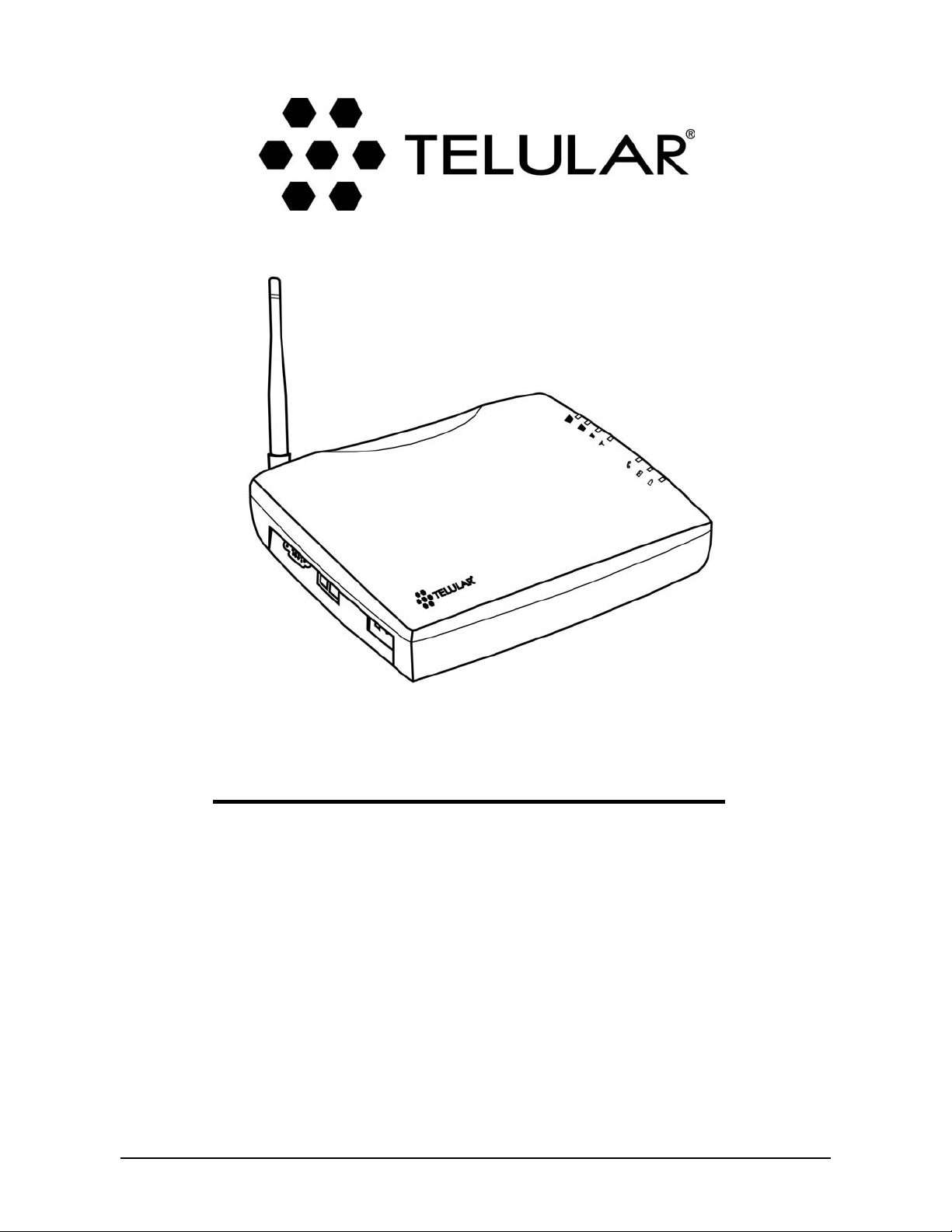
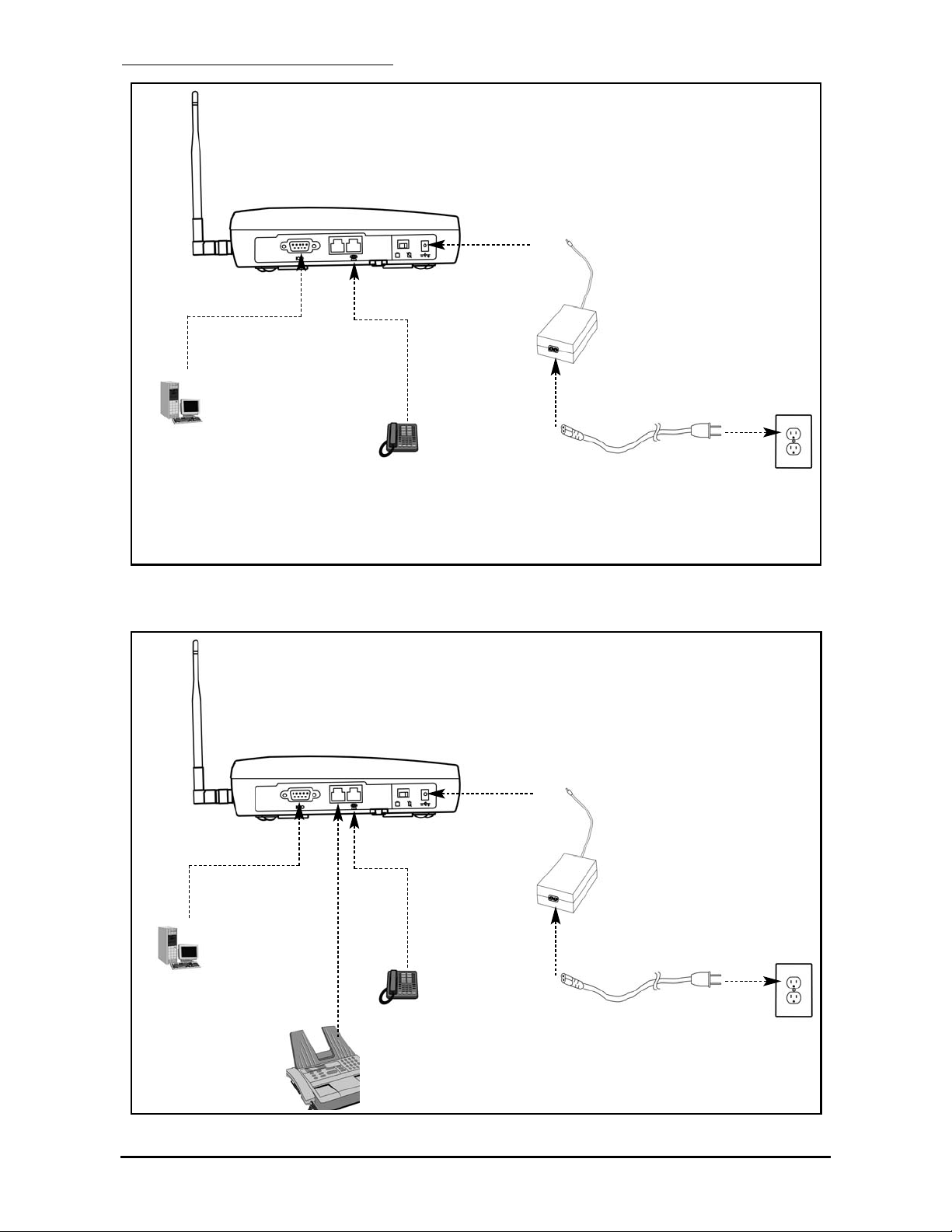
SX5 Fixed Wireless Terminal with Optional Analog Fax
SX5 Fixed Wireless Terminal
Phonecell®SX5 GSM iii User Manual
Extension Side
Trunk Side
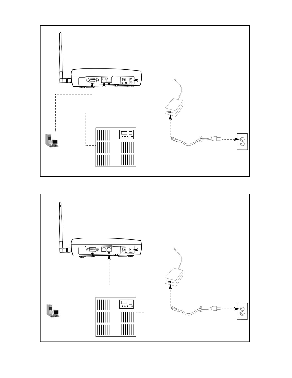
SX5 Fixed Wireless PBX Terminal (attached to Extension side of PBX)
SX5 Fixed Wireless PBX Terminal (attached to Trunk side of PBX)
Phonecell®SX5 GSM iv User Manual
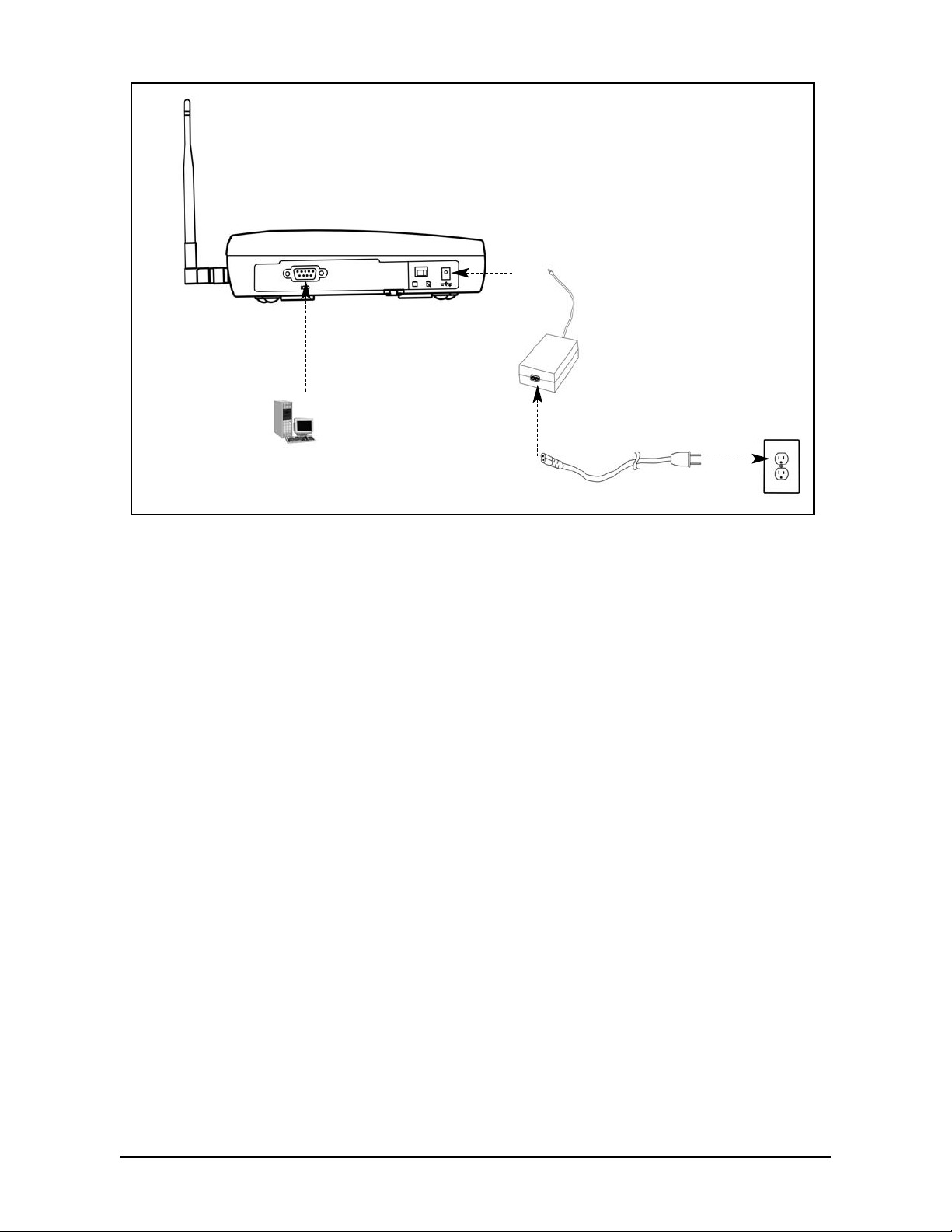
SX5 Fixed Wireless Modem
Phonecell®SX5 GSM v User Manual
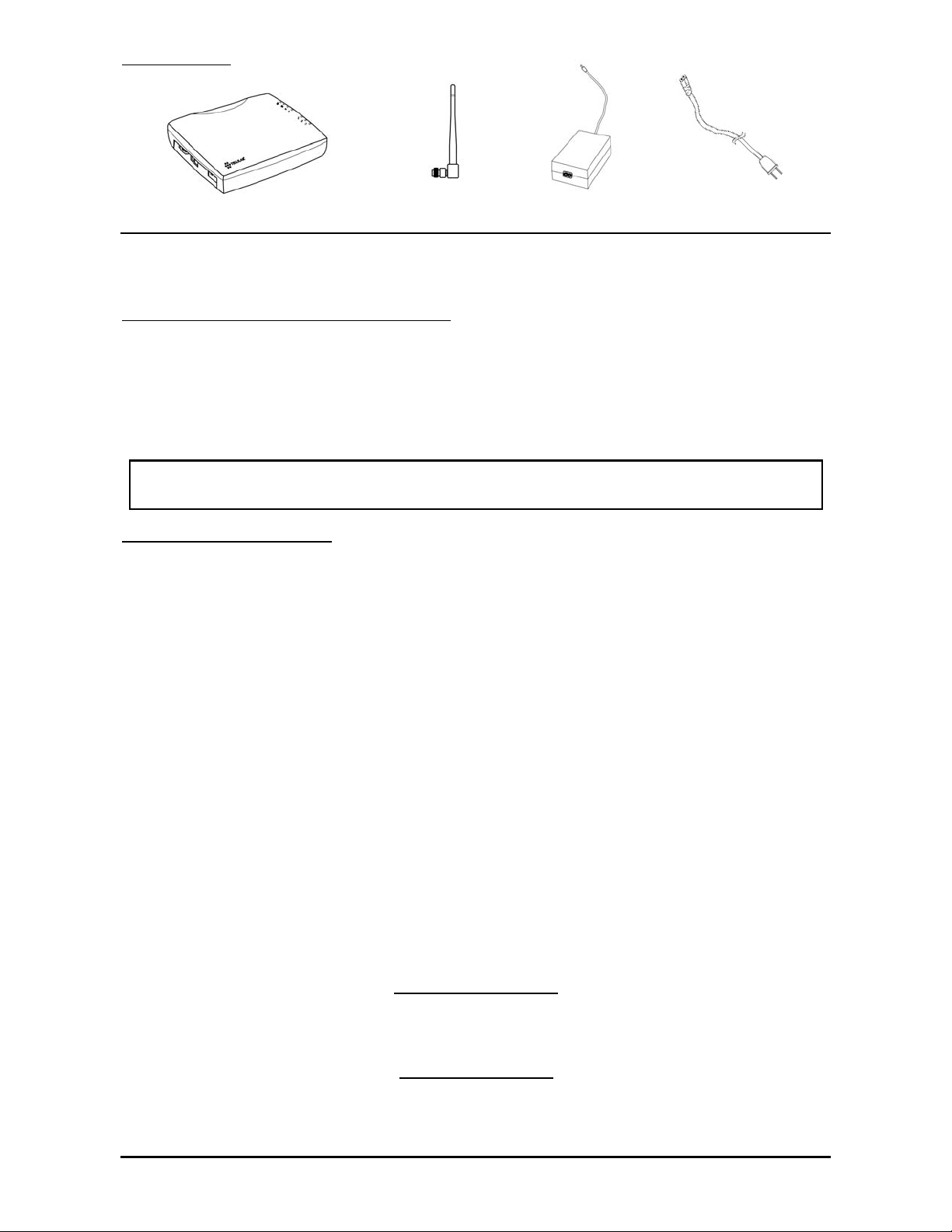
Before installing the Phonecell®SX5, carefully remove the contents from the shipping carton
and check for evidence of shipping damage. If damage is found, contact your Authorized
Telular Distributor or shipping agent immediately.
SAFE OPERATION INSTRUCTIONS
IMPORTANT! Before installing or operating this product, read the SAFETY INFORMATION
section of this manual.
••
Install the unit indoors.
••
Install the unit on a hard, flat surface for proper ventilation.
••
Do not expose the unit to rain or moisture.
••
Do not place the unit on or close to sources of heat.
IMPORTANT NOTICES
TERMS AND CONDITIONS FOR USE OF PHONECELL®PRODUCTS ("Product")
These Terms and Conditions are a legal contract between you and Telular Corporation for the title to
and use of the Product. BY RETAINING AND USING THE PRODUCT AFTER RECEIPT OF IT,
YOU AGREE TO THE TERMS AND CONDITIONS INCLUDING WARRANTY DISCLAIMERS,
LIMITATIONS OF LIABILITY AND INDEMNIFICATION PROVISIONS BELOW. IF YOU DO NOT
AGREE TO THE TERMS AND CONDITIONS, DO NOT USE THE PRODUCT AND IMMEDIATELY
RETURN THE UNUSED PRODUCT FOR A COMPLETE REFUND. You agree to accept sole
responsibility for any misuse of the Product by you; and, in addition, any negligent or illegal act or
omission of your or your agents, contractors, servants, employees, or other users of the Product so
long as the Product was obtained from you, in the use and operation of the Product.
INDEMNIFICATION OF TELULAR CORPORATION ("TELULAR")
YOU SHALL INDEMNIFY, DEFEND AND HOLD HARMLESS TELULAR FOR ANY OF THE COST, INCLUDING REASONABLE ATTORNEYS' FEES, AND FROM CLAIMS ARISING OUT OF YOU, YOUR CLIENTS' OR OTHER THIRD PARTIES'
USE OR OPERATION OF THE PRODUCT: (i) FOR MISUSE OR IN A MANNER NOT CONTEMPLATED BY YOU AND
TELULAR OR INCONSISTENT WITH THE PROVISIONS OF THIS MANUAL; (ii) IN AN ILLEGAL MANNER OR AGAINST
PUBLIC POLICY; (iii) IN A MANNER SPECIFICALLY UNAUTHORIZED IN THIS MANUAL; (iv) IN A MANNER HARMFUL
OR DANGEROUS TO THIRD PARTIES; (v) FROM CLAIMS BY ANYONE RESPECTING PROBLEMS, ERRORS OR MISTAKES OF THE PRODUCT; OR (vi) COMBINATION OF THE PRODUCT WITH MATERIAL, MODIFICATION OF THE
PRODUCT OR USE OF THE PRODUCT IN AN ENVIRONMENT NOT PROVIDED, OR PERMITTED, BY TELULAR IN
WRITING. THE PARTIES SHALL GIVE EACH OTHER PROMPT NOTICE OF ANY SUCH COST OR CLAIMS AND COOPERATE, EACH WITH THE OTHER, TO EFFECTUATE THIS INDEMNIFICATION, DEFENSE AND HOLD HARMLESS.
PLEASE SEE THE IMPORTANT NOTICES SECTION OF THIS MANUAL FOR
IMPORTANT INFORMATION ON USE, WARRANTY AND INDEMNIFICATION
CONTENTS
Telular Corporation
Corporate Headquarters
647 North Lakeview Parkway
Vernon Hills, Illinois 60061, USA
Technical Support
Tel: 847-247-9400 • Fax: 847-247-0021
E-mail: support@telular.com • http://www.telular.com
Phonecell®SX5 GSM FWT Spike Antenna
Part Number 56023504 ©2003 Telular Corporation, All Rights Reserved
Power Supply
AC Power Cord

Phonecell®SX5 GSM vi User Manual
TABLE OF CONTENTS
QUICK CONNECTION GUIDE ......................................................................................ii
IMPORTANT NOTICES..................................................................................................v
Technical Support .......................................................................................................v
SETUP............................................................................................................................1
Install the SIM Card ...................................................................................................1
Emergency Batteries..................................................................................................2
SX5 Location and Installation ....................................................................................3
Wall Mounting.............................................................................................................3
Connect the SX5 to AC Power...................................................................................4
Attach a Telephone to the SX5 ..................................................................................4
GETTING TO KNOW YOUR SX5..................................................................................5
LED Status Indicators ................................................................................................5
Important Dial Tones ..................................................................................................6
CALL FUNCTIONS ........................................................................................................7
Making Calls...............................................................................................................7
Receiving Calls ..........................................................................................................7
Ending Calls ...............................................................................................................7
In-Call Features..........................................................................................................7
SX5 USER FEATURES..................................................................................................8
Messages (Voice Mail and Text Messages)...............................................................8
Audio Settings ............................................................................................................8
Dial Settings ...............................................................................................................8
SIM Settings...............................................................................................................9
Caller ID .....................................................................................................................9
Setting Time and Date .............................................................................................10
Reset User Factory Defaults....................................................................................10
Dialing Prefix Setup .................................................................................................10
SUPPLEMENTARY SERVICE FEATURES (NETWORK DEPENDENT)....................11
Call Waiting ..............................................................................................................11
Calling Line Identification Presentation ....................................................................11
Calling Line Identification Restriction .......................................................................11
Connected Line Identification Presentation .............................................................12
Connected Line Identification Restriction.................................................................12
Call Forwarding ........................................................................................................12
Call Barring ..............................................................................................................13
Multiparty Call Features ...........................................................................................14
DATA FEATURES ........................................................................................................15
Connecting to a Computer .......................................................................................15
Dial-Up Connections ................................................................................................15
Automatic Baud Rate Fallback Control....................................................................15
Digital Fax Setup......................................................................................................16
GPRS (Packet Data) Connections...........................................................................16
Analog Modem Support ...........................................................................................16

SX5 GSM FWT WITH FAX ..........................................................................................19
Set SX5 for Analog Fax ...........................................................................................19
Connect SX5 for Dual Jack Mode............................................................................19
Connect SX5 for Single Jack Mode .........................................................................19
Fax Timing Adjustments...........................................................................................19
Analog Fax Bypass ..................................................................................................20
SX5 GSM PBX FWT ....................................................................................................21
Trunk Side PBX Connection (Trunk Mode)..............................................................21
Extension Side PBX Connection (Extension Mode) ................................................21
PBX Command Summary........................................................................................23
Auto-Routing Setup (GSM to Extension) .................................................................24
Two-Stage Extension Side Dialing (Extension to GSM) ..........................................24
SX5 TROUBLESHOOTING .........................................................................................25
CONFORMANCE STATEMENTS ................................................................................26
SAFETY INFORMATION .............................................................................................26
WARRANTY.................................................................................................................29
APPENDIX A: PC SERIAL PORT SETUP FOR CS FAX AND DATA ........................31
Phonecell®SX5 GSM vii User Manual
SETUP
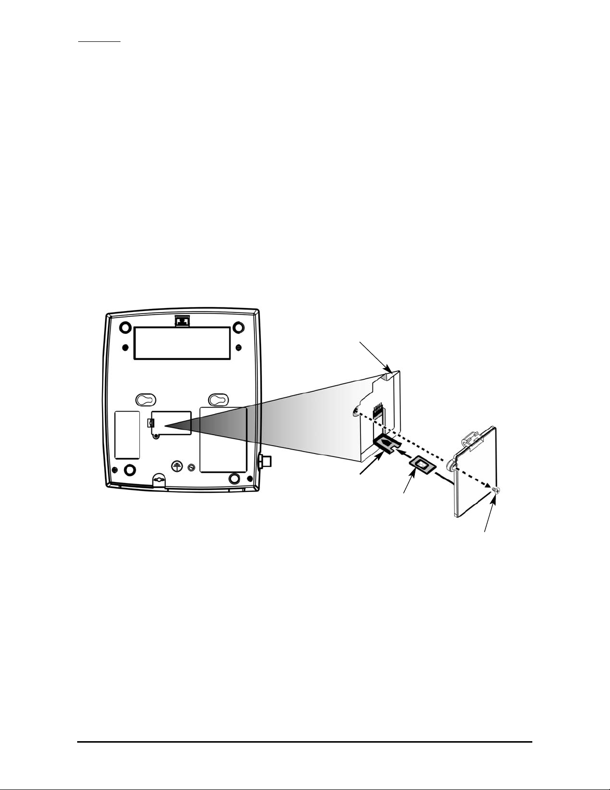
Install the SIM Card
The SX5 requires a Subscriber Identity Module (SIM) for normal operation. The service provider
supplies the SIM card, which carries the account information needed to operate the SX5. If you
don’t have a SIM card, contact your service provider. The SIM compartment is on the back of the
SX5 - see Figure 1.
HINT: Make sure your carrier disables SIM PIN1 or you will have to enter the PIN every time the
unit powers on. See the SX5e User Features section of this manual for more information.
1. Disconnect the power supply. The power supply must be disconnected whenever a SIM Card
is installed.
2. Remove the SIM compartment cover by removing the screw - see Figures 1 and 2.
3. Open the SIM compartment holder.
4. Line up the SIM card with the arrow on the SIM card holder - see Figure 2.
5. Gently insert the SIM card in the slot of the SIM card holder.
6. Close the SIM card holder.
NOTE: Do not force the SIM card holder shut. Make sure the SIM card is aligned properly
with the directional arrow on the holder.
7. Reattach the SIM compartment cover with the screw.
Phonecell
®
SX5 GSM 1 User Manual
SIM
Compartment
Cover
SIM Card
Holder
SIM Card
Cover Screw
Figure 2 - Install the SIM Card.Figure 1 - SIM compartment.
Emergency Batteries
Install Batteries
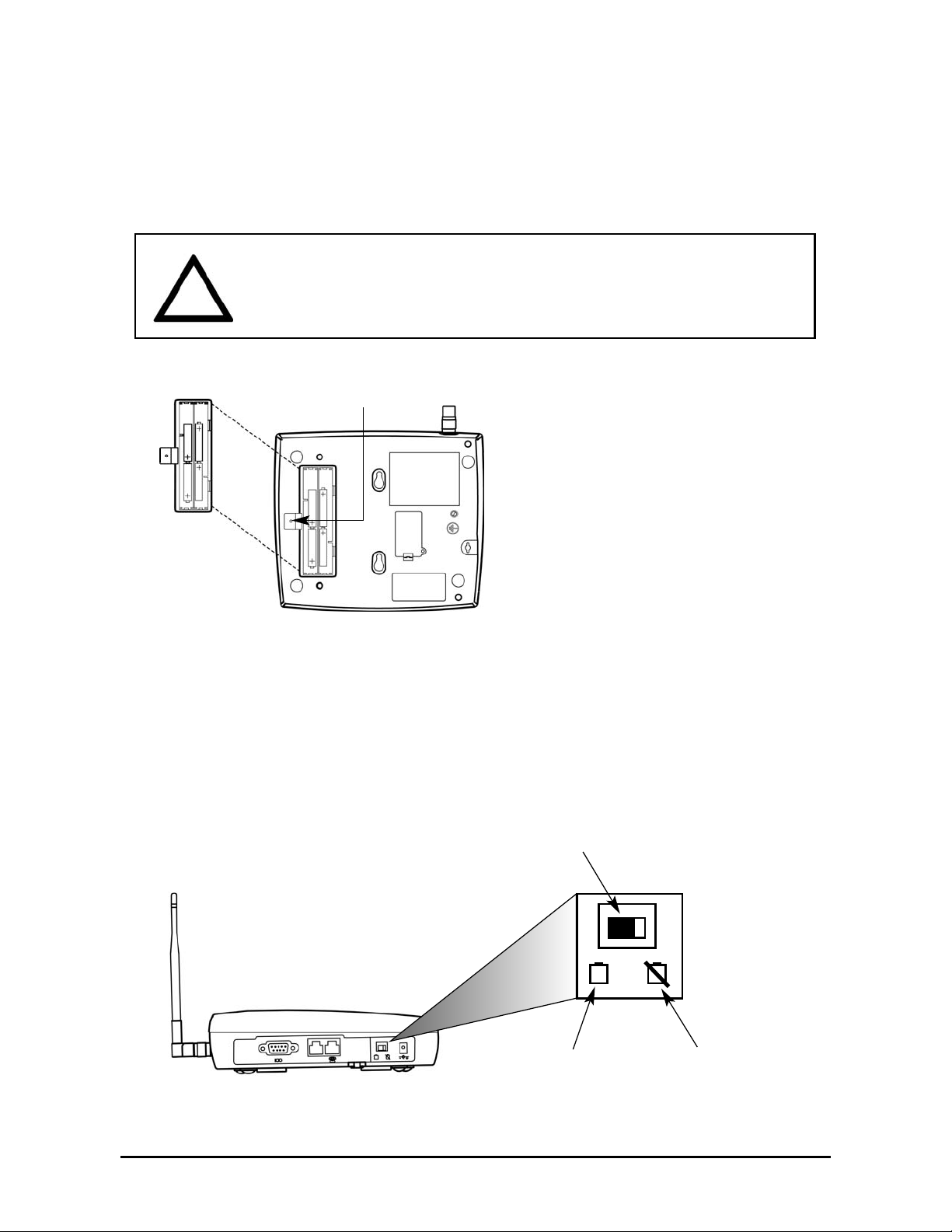
1. Remove the battery access door screw located on the bottom of the unit - see Figure 3.
2. Press the battery access door tabs and remove the battery access door.
3. Install 4 “AA” alkaline batteries (not supplied) - see Figure 3.
4. Reinstall the battery access door using the screw.
5. Turn the AC/Battery switch to battery operation - see Figure 4.
NOTE: The SX5 does not support rechargeable batteries.
Battery Operation
The unit will not automatically switch from AC to battery upon loss of AC power. The AC/Battery
switch must be changed manually - see Figure 4. Battery power will provide up to three hours of
standby and 90 minutes of talk time, depending on the SX5 model.
Phonecell
®
SX5 GSM 2 User Manual
AC/Battery Switch
Figure 4 – SX5 AC/Battery switch.
Battery Position AC Position
WARNING!
Only “AA” alkaline batteries are to be used with the Phonecell®SX5.
Use of any other batteries may result in fire and/or other damage to the unit.
!
Battery
Access
Door
Battery Access
Door Screw
Figure 3 – SX5 battery installation.
Phonecell®SX5 GSM 3 User Manual
SX5 Location and Installation
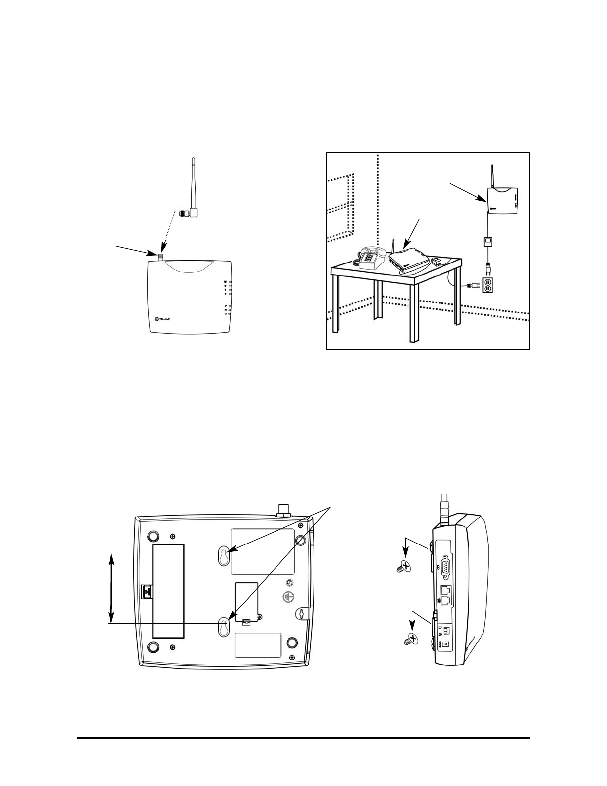
The SX5 comes with a standard spike antenna (TNC) - see Figure 5. For optimal signal
strength, choose a location that is above ground and as close to windows (or exterior walls) as
possible - see Figure 6. Cellular signal strength is displayed by the Received Signal Strength
Indicator (RSSI) LED on the unit - See the How to Use the LED Status Indicators section of this
manual.
1. Connect the antenna to the terminal - see Figure 5.
2. Finger-tighten the antenna. Do not over-tighten the antenna.
Wall Mounting
1. Mark two hole locations 98,5 mm (3-7/8 inches) vertically apart and drill two holes into the
wall.
2. Install the screws (not supplied) into the wall, leaving a gap (approximately 3 mm (1/8 inch))
between screw head and wall.
3. Align the mounting holes with the screws and mount the SX5 onto the screws - see Figures
7 and 8.
Figure 6 – Typical SX5 installation.
Wall Mount
Figure 5 –
SX5 antenna connection.
Spike
antenna
TNC Antenna
Connector
Table Mount
Figure 7 – SX5 mounting holes.
Figure 8 – Mount the SX5 onto the screws.
Mounting Holes
98,5 mm (3 7/8”)
Phonecell®SX5 GSM 4 User Manual
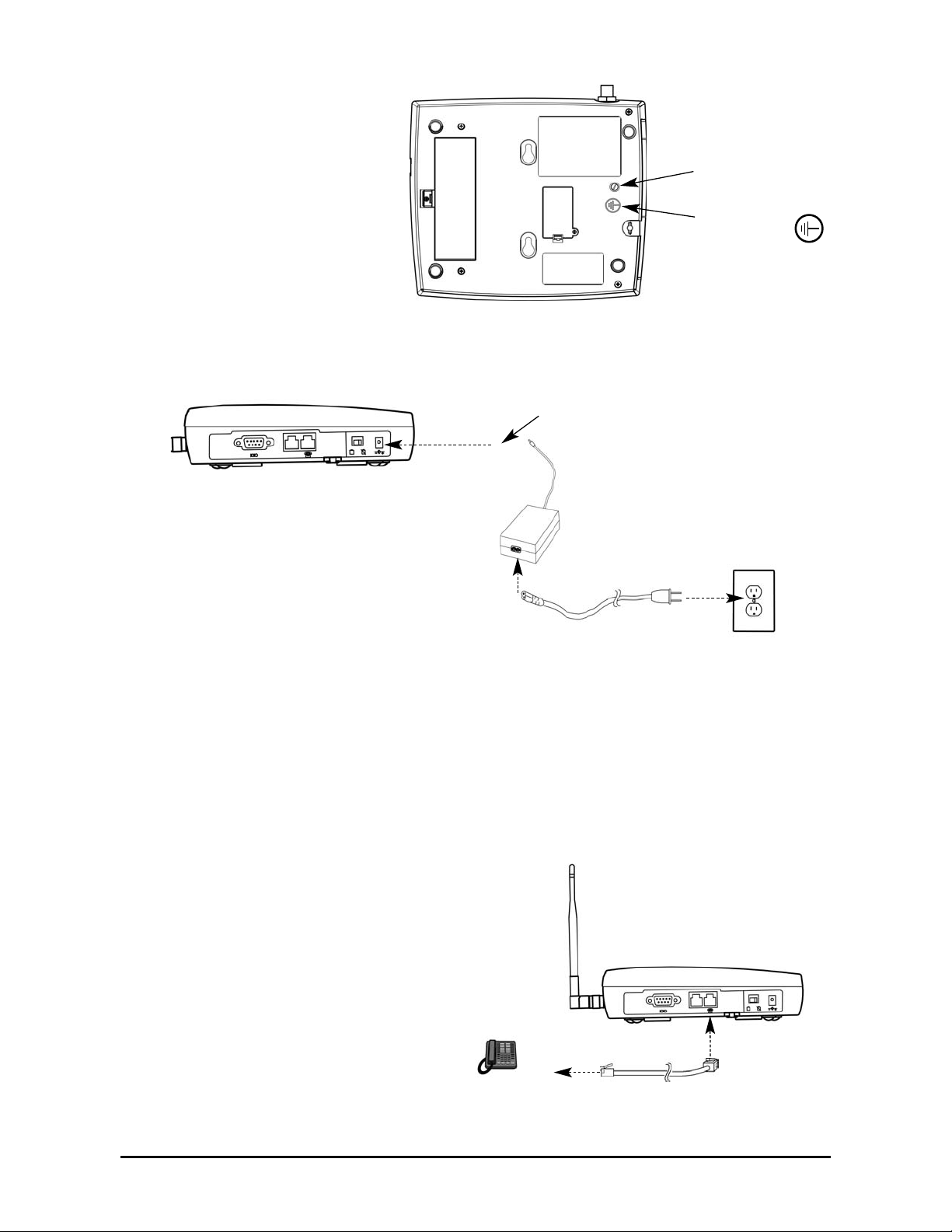
Connect the SX5 to AC Power
1. A protective earth (safety
ground) terminal (screw)
marked with a protective
earth symbol is provided
on the back of the SX5 see Figure 9a. Connect
this terminal to a good
earth ground (i.e., a cold
water pipe) by means of
an 18 gauge or heavier
insulated wire. The wire
insulation should be
green with a yellow stripe
to indicate that this is a
protective earth (safety
ground) connection.
2. Connect the barrel connector of the power supply to the AC power input receptacle of the
SX5 - see Figure 9b.
3. Plug the AC power cord into the power supply.
4. Plug the AC power cord into the AC Power outlet.
HINT: If there are no batteries in the SX5, it will only power on if the AC/Battery switch is in
the AC position - see Figure 4.
5. Check the cellular signal strength and move the unit until you achieve the best signal
possible - see the LED Status Indicators section of this manual.
Attach a Telephone to the SX5
1. Plug one end of a standard phone
cord into a phone- see Figure 10.
2. Connect the other end of the phone
cord to the telephone port on the side
of the SX5 (marked with a phone icon)
- see Figure 10.
Figure 9a –
Earth ground terminal screw.
Protective earth
(safety ground)
terminal screw
Protective earth
symbol
Figure 9b –
Connect the SX5e to AC Power.
AC Power
AC Power Input
AC Power Cord
Power
Supply
Barrel Connector
Figure 10 - Connect SX5 to Telephone.
Phonecell®SX5 GSM 5 User Manual
GETTING TO KNOW YOUR SX5
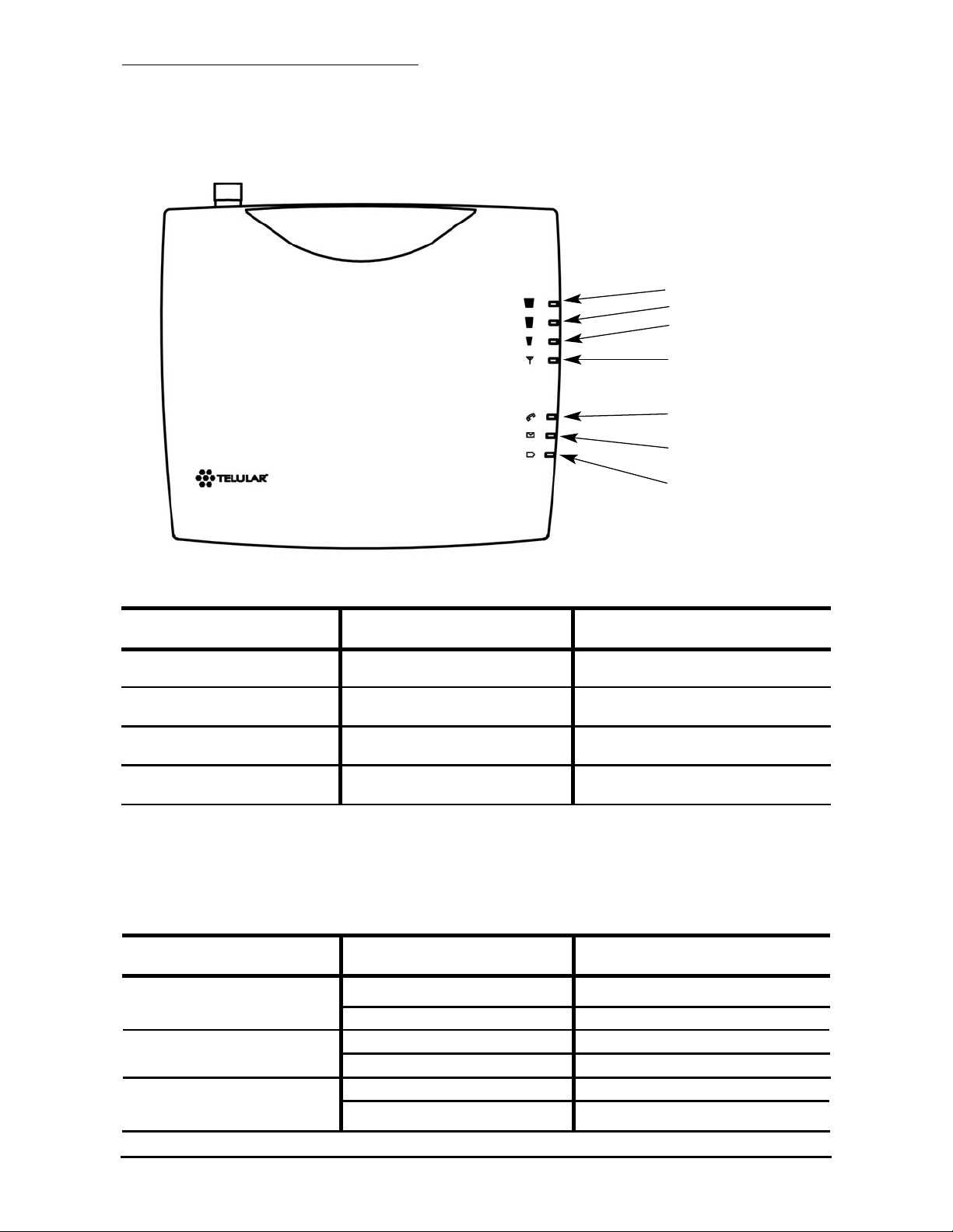
LED Status Indicators
The LED indicators are activated when the SX5 is powered on. The following tables describe the
modes and operation of the indicators.
NOTE: If you are getting no service or limited service, contact your service provider for more information.
RSSI 3
RSSI 2
RSSI 1
Service Indicator
Hook Indicator
Message Indicator
Power/Battery
* Contact your service provider to verify that service has been activated.
** Indicates that the SIM card is missing or has been improperly installed. If the SIM card is properly installed and the error
continues, contact your service provider.
Service Indicator
LED Color Activity Description
Green Continuous Full Service
Amber Continuous Limited Service
Red Continuous No Service*
Red Flashing SIM Error**
Received Signal Strength Indicator (RSSI)
RSSI LED's Activity Cellular Signal Strength
Flashing Lowest
Continuous Poor
Flashing Fair
Continuous Good
Flashing Very Good
Continuous Best
RSSI 1
RSSI 2
RSSI 3

Important Dial Tones
Service - Indicates that phone is ready for use (steady tone).
No Service - Indicates that there is no service available (fast beeping tone).
Roam - Indicates service in a roam area.
Not Registered - Indicates inactive or missing SIM card, or need to enter PIN (fast stutter tone).
Supplementary Service - Indicates that supplementary services have been activated.
Phonecell
®
SX5 GSM 6 User Manual
Hook Indicator
LED Color Activity Description
Green Flashing (with ringer) Incoming call
Green Continuous FWT is off hook
Green Fast Flashing Processing data call
Green Slow Flashing Call on hold
Message Indicator
LED Color Activity Description
Green Slow Flashing New voice mail or text message
AC Power/Battery Indicator
LED Color Activity Description
Green Continuous AC power applied
Amber Continuous Battery level good
(battery switch on)
Amber/Green Alternating Battery level poor
(battery switch on)

CALL FUNCTIONS
1
Making Calls
1. Pick up the telephone handset (the phone is now “off-hook”).
2. Listen for dial tone. If service is not available, a No-Service tone is produced. Hang-up the
phone and try again. If the No-Service tone continues, contact your service provider to verify
that cellular service is available.
3. Dial the phone number. The call will be sent automatically.
HINT: Pressing the Flash key or pressing and releasing the switch-hook after dialing a number will send the call immediately.
Receiving Calls
When the telephone rings, pick up the handset and begin talking.
Ending Calls
Hang-up the phone (place the handset back onto the telephone cradle).
In-Call Features
Place a Call on Hold
2, 3
To place a call on hold, press the Flash key on your phone. If your phone does not have a Flash
key, press and release the Switch-Hook. When the call is on hold, the Hook Indicator LED
will flash and you will hear a dial tone on your phone. If you hang-up your phone when a call is
on hold, the call will be disconnected.
Retrieve a Call on Hold
Press the Flash key or press and release the switch-hook to go back to your held call.
Make a New Call with a Call on Hold (Two-Line Calling)
2, 3
If you want to make another call when the first call is placed on hold, dial the number when you
hear a dial tone after the call has been placed on hold. See Place a Call on Hold above. You
cannot go back and forth between calls. If you hang-up the phone all calls will be disconnected.
Answer Call Waiting
2, 3
When you're on an active call, you will hear a beep tone on your phone when a new call is
incoming. To answer the new call and place the first call on hold, press Flash or press and
release the Switch-Hook.
Answer a Call when Dialing or Off Hook with Dial Tone
Sometimes you may receive a call as you are dialing or when your just about to dial a number. If
this happens, you will hear a call waiting tone (beep tone) on your phone. Press Flash or press
and release the Switch-Hook to answer the call.
Adjust the Volume Level
If the volume level on the phone is too high or too low, adjust the levels using the keypad on the
telephone. The telephone must be in Tone-Dial (DTMF) mode to adjust the levels.
• To Increase Volume press: #
*
8 #
• To Decrease Volume press: # *3 #
NOTE: The default setting allows adjustment of the volume three (3) steps from the default in
either direction (Up or Down). The volume setting remains in effect for future calls until changed
manually. When power to the SX5 is cycled (powered OFF/ON), the default mid-range volume
setting will be restored.
1
Not available on Fixed Wireless Modem models
2
Not available on Fixed Wireless PBX Terminal models
3
Call Hold, Call Waiting, and Two-Line Calling are all network dependent features. Contact your service
provider for information on activating these features.
Phonecell®SX5 GSM 7 User Manual
 Loading...