

Page 1

OmniAccess SafeGuard
OS Administration
Guide
Release 3.0.2
PART NUMBER: 005-0033 REV A1
UBLISHED: MARCH 2007
P
A
LCATEL-LUCENT
26801 WEST AGOURA ROAD
CALABASAS, CA 91301 USA
(818) 880-3500
WWW.ALCATEL-LUCENT.COM
Page 2

Alcatel-Lucent Proprietary
Copyright © 2007 Alcatel-Lucent. All rights reserved. This document may not be reproduced in whole
or in part without the expressed written permission Alcatel-Lucent. Alcatel-Lucent ® and the AlcatelLucent logo are registered trademarks of Alcatel-Lucent. All other trademarks are the property of their
respective owners.
2
OmniAccess SafeGuard OS Administration Guide
Page 3

Contents
Preface
About This Guide. . . . . . . . . . . . . . . . . . . . . . . . . . . . . . . . . . . . . . . . . . . . . . . . . . . . . . . . . . . . . . . . . .16
Audience. . . . . . . . . . . . . . . . . . . . . . . . . . . . . . . . . . . . . . . . . . . . . . . . . . . . . . . . . . . . . . . . . . . . .16
Conventions Used in This Guide . . . . . . . . . . . . . . . . . . . . . . . . . . . . . . . . . . . . . . . . . . . . . . . . . .16
Related Publications. . . . . . . . . . . . . . . . . . . . . . . . . . . . . . . . . . . . . . . . . . . . . . . . . . . . . . . . . . . . . . .17
Additional Resources . . . . . . . . . . . . . . . . . . . . . . . . . . . . . . . . . . . . . . . . . . . . . . . . . . . . . . . . . . . 17
Guide Organization . . . . . . . . . . . . . . . . . . . . . . . . . . . . . . . . . . . . . . . . . . . . . . . . . . . . . . . . . . . . . . . 17
Chapter 1: SafeGuard OS Overview
Alcatel-Lucent Solution and Product Overview . . . . . . . . . . . . . . . . . . . . . . . . . . . . . . . . . . . . . . . . 20
Deployment Models. . . . . . . . . . . . . . . . . . . . . . . . . . . . . . . . . . . . . . . . . . . . . . . . . . . . . . . . . . . . . . .22
Understanding Protection Modes. . . . . . . . . . . . . . . . . . . . . . . . . . . . . . . . . . . . . . . . . . . . . . . . . . . . 24
SafeGuard OS Overall Feature Summary . . . . . . . . . . . . . . . . . . . . . . . . . . . . . . . . . . . . . . . . . . . . . 26
Chapter 2: Accessing and Managing the System
Connecting to a SafeGuard Device Console. . . . . . . . . . . . . . . . . . . . . . . . . . . . . . . . . . . . . . . . . .28
Accessing the SafeGuard Device Command Line Interface . . . . . . . . . . . . . . . . . . . . . . . . . . . . .28
Using Telnet . . . . . . . . . . . . . . . . . . . . . . . . . . . . . . . . . . . . . . . . . . . . . . . . . . . . . . . . . . . . . . . . . . .29
Enabling and Disabling Telnet . . . . . . . . . . . . . . . . . . . . . . . . . . . . . . . . . . . . . . . . . . . . . . . . 29
Displaying the Current Telnet and Serial Port Connections . . . . . . . . . . . . . . . . . . . . . . . .29
Closing a Telnet or SSH Session. . . . . . . . . . . . . . . . . . . . . . . . . . . . . . . . . . . . . . . . . . . . . . . . 30
Specifying the Maximum Number of Telnet Connections Allowed. . . . . . . . . . . . . . . . . .30
Setting the Telnet Connection Session Timeout . . . . . . . . . . . . . . . . . . . . . . . . . . . . . . . . . . 30
Using Secure Shell (SSH) . . . . . . . . . . . . . . . . . . . . . . . . . . . . . . . . . . . . . . . . . . . . . . . . . . . . . . . . .31
Enabling an SSH Session . . . . . . . . . . . . . . . . . . . . . . . . . . . . . . . . . . . . . . . . . . . . . . . . . . . . .32
Downloading SSH Key Files from TFTP Server. . . . . . . . . . . . . . . . . . . . . . . . . . . . . . . . . . . . .32
Generating DSA, RSA, RSA Keys. . . . . . . . . . . . . . . . . . . . . . . . . . . . . . . . . . . . . . . . . . . . . . .33
Deleting DSA, RSA, RSA Keys. . . . . . . . . . . . . . . . . . . . . . . . . . . . . . . . . . . . . . . . . . . . . . . . . .33
Changing SSH Protocols . . . . . . . . . . . . . . . . . . . . . . . . . . . . . . . . . . . . . . . . . . . . . . . . . . . . .34
Limiting SSH Sessions. . . . . . . . . . . . . . . . . . . . . . . . . . . . . . . . . . . . . . . . . . . . . . . . . . . . . . . . .34
Setting the SSH Timer . . . . . . . . . . . . . . . . . . . . . . . . . . . . . . . . . . . . . . . . . . . . . . . . . . . . . . . .35
Displaying SSH Configuration Information. . . . . . . . . . . . . . . . . . . . . . . . . . . . . . . . . . . . . . . 35
Customizing and Working with the Command Line Interface Default Settings . . . . . . . . . . .36
Changing the System Command Prompt . . . . . . . . . . . . . . . . . . . . . . . . . . . . . . . . . . . . . .37
Setting a Maximum Serial Console Connect Time. . . . . . . . . . . . . . . . . . . . . . . . . . . . . . . .37
OmniAccess SafeGuard OS Administration Guide
3
Page 4

Contents
Enabling and Disabling CLI Display Paging . . . . . . . . . . . . . . . . . . . . . . . . . . . . . . . . . . . . .37
Uploading a New CLI Banner File . . . . . . . . . . . . . . . . . . . . . . . . . . . . . . . . . . . . . . . . . . . . . 38
Uploading the CLI Log File . . . . . . . . . . . . . . . . . . . . . . . . . . . . . . . . . . . . . . . . . . . . . . . . . . .38
Copying the System Diagnostics File. . . . . . . . . . . . . . . . . . . . . . . . . . . . . . . . . . . . . . . . . . .38
Copying the System Debug File. . . . . . . . . . . . . . . . . . . . . . . . . . . . . . . . . . . . . . . . . . . . . . .39
Displaying the Current HTTP Information . . . . . . . . . . . . . . . . . . . . . . . . . . . . . . . . . . . . . . . .39
Exiting or Logging Out of a Command Line Session . . . . . . . . . . . . . . . . . . . . . . . . . . . . . . . . . 39
Configuring Management Users. . . . . . . . . . . . . . . . . . . . . . . . . . . . . . . . . . . . . . . . . . . . . . . . . . . . . 39
Configuring Management Users. . . . . . . . . . . . . . . . . . . . . . . . . . . . . . . . . . . . . . . . . . . . . . . . . .40
Adding Management Users to the Database . . . . . . . . . . . . . . . . . . . . . . . . . . . . . . . . . . .40
Displaying the Management Users . . . . . . . . . . . . . . . . . . . . . . . . . . . . . . . . . . . . . . . . . . . . 41
Setting a Password for the Default Admin Account . . . . . . . . . . . . . . . . . . . . . . . . . . . . . .42
Configuring Local Authentication for Management Users. . . . . . . . . . . . . . . . . . . . . . . . .43
Assigning a Login List to the Default Login User . . . . . . . . . . . . . . . . . . . . . . . . . . . . . . . . . . . . .44
Configuring RADIUS Users for Management Users . . . . . . . . . . . . . . . . . . . . . . . . . . . . . . . . . . .45
Clearing All Passwords. . . . . . . . . . . . . . . . . . . . . . . . . . . . . . . . . . . . . . . . . . . . . . . . . . . . . . . . . .46
Managing Out-of-Band Management Port . . . . . . . . . . . . . . . . . . . . . . . . . . . . . . . . . . . . . . . . . . . 46
Setting the IP Configuration Protocol. . . . . . . . . . . . . . . . . . . . . . . . . . . . . . . . . . . . . . . . . . . . . .46
Setting the IP Address, Netmask, and Gateway of the System . . . . . . . . . . . . . . . . . . . . . . . .47
Enabling or Disabling the Management Port . . . . . . . . . . . . . . . . . . . . . . . . . . . . . . . . . . . . . . .47
Setting Speed and Duplex for the Management Port. . . . . . . . . . . . . . . . . . . . . . . . . . . . . . . . 48
Displaying Configuration Information for the Management Port. . . . . . . . . . . . . . . . . . . . . . .48
Displaying Address Resolution Protocol Information . . . . . . . . . . . . . . . . . . . . . . . . . . . . . . . . .51
Setting Up the System Time and Date (SNTP) . . . . . . . . . . . . . . . . . . . . . . . . . . . . . . . . . . . . . . . . . .51
Manually Setting the Time and Date . . . . . . . . . . . . . . . . . . . . . . . . . . . . . . . . . . . . . . . . . . . . . .51
Configuring SNTP . . . . . . . . . . . . . . . . . . . . . . . . . . . . . . . . . . . . . . . . . . . . . . . . . . . . . . . . . . . . . .54
Optional SNTP Client Configurations . . . . . . . . . . . . . . . . . . . . . . . . . . . . . . . . . . . . . . . . . . . . . .58
Setting the Poll Interval . . . . . . . . . . . . . . . . . . . . . . . . . . . . . . . . . . . . . . . . . . . . . . . . . . . . . . 58
Setting the Poll Retry and Poll-Timeout Timers for Unicast Clients. . . . . . . . . . . . . . . . . . . . 58
Setting the Port ID for the Port Client. . . . . . . . . . . . . . . . . . . . . . . . . . . . . . . . . . . . . . . . . . . 59
Managing Device Information . . . . . . . . . . . . . . . . . . . . . . . . . . . . . . . . . . . . . . . . . . . . . . . . . . . . . .60
Clearing the Counters . . . . . . . . . . . . . . . . . . . . . . . . . . . . . . . . . . . . . . . . . . . . . . . . . . . . . . . . . .60
Checking for Another Computer on the Network . . . . . . . . . . . . . . . . . . . . . . . . . . . . . . . . . . . 60
Displaying Version Information . . . . . . . . . . . . . . . . . . . . . . . . . . . . . . . . . . . . . . . . . . . . . . . . . . .61
Displaying Hardware Information. . . . . . . . . . . . . . . . . . . . . . . . . . . . . . . . . . . . . . . . . . . . . . . . .63
Displaying the Serial Communication Settings for the Device . . . . . . . . . . . . . . . . . . . . . . . . .65
Setting Up a Trace Route. . . . . . . . . . . . . . . . . . . . . . . . . . . . . . . . . . . . . . . . . . . . . . . . . . . . . . . . 66
Managing Network Information . . . . . . . . . . . . . . . . . . . . . . . . . . . . . . . . . . . . . . . . . . . . . . . . . . . . .67
Configuring the Network MAC Address. . . . . . . . . . . . . . . . . . . . . . . . . . . . . . . . . . . . . . . . . . . .67
Configuring the Network MAC Type . . . . . . . . . . . . . . . . . . . . . . . . . . . . . . . . . . . . . . . . . . . . . . 67
Configuring the Network VLAN ID . . . . . . . . . . . . . . . . . . . . . . . . . . . . . . . . . . . . . . . . . . . . . . . .68
Configuring the Network Protocol . . . . . . . . . . . . . . . . . . . . . . . . . . . . . . . . . . . . . . . . . . . . . . . .68
4
OmniAccess SafeGuard OS Administration Guide
Page 5

Contents
Configuring SNMP on the Device . . . . . . . . . . . . . . . . . . . . . . . . . . . . . . . . . . . . . . . . . . . . . . . . . . . . 68
Setting the SNMP Name . . . . . . . . . . . . . . . . . . . . . . . . . . . . . . . . . . . . . . . . . . . . . . . . . . . . . . . .69
Setting the SNMP Physical Location. . . . . . . . . . . . . . . . . . . . . . . . . . . . . . . . . . . . . . . . . . . . . . .69
Designating the SNMP Contact . . . . . . . . . . . . . . . . . . . . . . . . . . . . . . . . . . . . . . . . . . . . . . . . . .70
Configuring SNMP Communities. . . . . . . . . . . . . . . . . . . . . . . . . . . . . . . . . . . . . . . . . . . . . . . . . .70
Adding and Naming a New SNMP Community. . . . . . . . . . . . . . . . . . . . . . . . . . . . . . . . . . 70
Establishing Access for the SNMP Community . . . . . . . . . . . . . . . . . . . . . . . . . . . . . . . . . . .71
Setting a Client IP Address for an SNMP Community. . . . . . . . . . . . . . . . . . . . . . . . . . . . . . 71
Setting a Client Netmask SNMP Community . . . . . . . . . . . . . . . . . . . . . . . . . . . . . . . . . . . . 72
Configuring a SNMP Target. . . . . . . . . . . . . . . . . . . . . . . . . . . . . . . . . . . . . . . . . . . . . . . . . . . . . . 72
Creating the Trap Receiver . . . . . . . . . . . . . . . . . . . . . . . . . . . . . . . . . . . . . . . . . . . . . . . . . . 72
Changing the IP Address of a Trap Receiver . . . . . . . . . . . . . . . . . . . . . . . . . . . . . . . . . . . .72
Changing the Trap Receiver Version. . . . . . . . . . . . . . . . . . . . . . . . . . . . . . . . . . . . . . . . . . .73
Enabling and Disabling SNMP Traps. . . . . . . . . . . . . . . . . . . . . . . . . . . . . . . . . . . . . . . . . . . . . . . 73
Displaying SNMP Community Information. . . . . . . . . . . . . . . . . . . . . . . . . . . . . . . . . . . . . . . . . .74
Displaying SNMP Target Information . . . . . . . . . . . . . . . . . . . . . . . . . . . . . . . . . . . . . . . . . . . . . .75
Displaying SNMP System Information . . . . . . . . . . . . . . . . . . . . . . . . . . . . . . . . . . . . . . . . . . . . . .75
Configuring Domain Name Servers . . . . . . . . . . . . . . . . . . . . . . . . . . . . . . . . . . . . . . . . . . . . . . . . . . 77
Specifying a Default Domain . . . . . . . . . . . . . . . . . . . . . . . . . . . . . . . . . . . . . . . . . . . . . . . . . . . .77
Creating a DNS Name Server List . . . . . . . . . . . . . . . . . . . . . . . . . . . . . . . . . . . . . . . . . . . . . . . . .78
Displaying DNS Information. . . . . . . . . . . . . . . . . . . . . . . . . . . . . . . . . . . . . . . . . . . . . . . . . . . . . . 78
Resetting the Device . . . . . . . . . . . . . . . . . . . . . . . . . . . . . . . . . . . . . . . . . . . . . . . . . . . . . . . . . . . . . .79
Configuring Data Traffic Ports . . . . . . . . . . . . . . . . . . . . . . . . . . . . . . . . . . . . . . . . . . . . . . . . . . . . . . .79
Entering Interface Configuration Mode . . . . . . . . . . . . . . . . . . . . . . . . . . . . . . . . . . . . . . . . . . .79
Enabling and Disabling an Interface . . . . . . . . . . . . . . . . . . . . . . . . . . . . . . . . . . . . . . . . . . . . . . 80
Displaying Interface Information . . . . . . . . . . . . . . . . . . . . . . . . . . . . . . . . . . . . . . . . . . . . . . . . .80
Displaying Ethernet Interface Information. . . . . . . . . . . . . . . . . . . . . . . . . . . . . . . . . . . . . . . . . .82
Switchport Statistics Display Information. . . . . . . . . . . . . . . . . . . . . . . . . . . . . . . . . . . . . . . .89
Additional Statistics Display Information . . . . . . . . . . . . . . . . . . . . . . . . . . . . . . . . . . . . . . . .90
Understanding Mirroring and Monitoring Ports . . . . . . . . . . . . . . . . . . . . . . . . . . . . . . . . . . . . . .91
About Remote Span Support. . . . . . . . . . . . . . . . . . . . . . . . . . . . . . . . . . . . . . . . . . . . . . . . .91
Configuring Port-Based Mirroring . . . . . . . . . . . . . . . . . . . . . . . . . . . . . . . . . . . . . . . . . . . . . . . . .93
Setting the Source or Destination Port. . . . . . . . . . . . . . . . . . . . . . . . . . . . . . . . . . . . . . . . . .93
Restoring the Default Mirror Session Mode . . . . . . . . . . . . . . . . . . . . . . . . . . . . . . . . . . . . . .94
Showing the Monitor Session . . . . . . . . . . . . . . . . . . . . . . . . . . . . . . . . . . . . . . . . . . . . . . . . .94
Changing the Protection Mode of Ports . . . . . . . . . . . . . . . . . . . . . . . . . . . . . . . . . . . . . . . . . . .95
For the SafeGuard Controller . . . . . . . . . . . . . . . . . . . . . . . . . . . . . . . . . . . . . . . . . . . . . . . . . 96
For the SafeGuard Switch. . . . . . . . . . . . . . . . . . . . . . . . . . . . . . . . . . . . . . . . . . . . . . . . . . . .97
Displaying Protection Mode Information . . . . . . . . . . . . . . . . . . . . . . . . . . . . . . . . . . . . . . .98
Configuring High Availability Support. . . . . . . . . . . . . . . . . . . . . . . . . . . . . . . . . . . . . . . . . . . . . . . .100
Configuring Fail-over Device Support . . . . . . . . . . . . . . . . . . . . . . . . . . . . . . . . . . . . . . . . . . . .100
Configuring System Recovery. . . . . . . . . . . . . . . . . . . . . . . . . . . . . . . . . . . . . . . . . . . . . . . . . . .105
Configuring Exception Recovery . . . . . . . . . . . . . . . . . . . . . . . . . . . . . . . . . . . . . . . . . . . . . . . . 106
Enabling and Disabling Exception Recovery . . . . . . . . . . . . . . . . . . . . . . . . . . . . . . . . . . .106
OmniAccess SafeGuard OS Administration Guide
5
Page 6

Contents
Changing the Exception Recovery Parameters . . . . . . . . . . . . . . . . . . . . . . . . . . . . . . . .107
Enabling System Reboots on LSP Watchdog Events . . . . . . . . . . . . . . . . . . . . . . . . . . . . .108
Viewing the Exception Recovery Status . . . . . . . . . . . . . . . . . . . . . . . . . . . . . . . . . . . . . . .108
Chapter 3: Working with Configuration Files and Upgrading Images
Understanding Configuration Files . . . . . . . . . . . . . . . . . . . . . . . . . . . . . . . . . . . . . . . . . . . . . . . . . .110
Saving Changes to the Running Configuration . . . . . . . . . . . . . . . . . . . . . . . . . . . . . . . . . . . .110
From Running to the Startup. . . . . . . . . . . . . . . . . . . . . . . . . . . . . . . . . . . . . . . . . . . . . . . . .110
From Running to External Storage . . . . . . . . . . . . . . . . . . . . . . . . . . . . . . . . . . . . . . . . . . . .111
Saving Changes to the Startup Configuration . . . . . . . . . . . . . . . . . . . . . . . . . . . . . . . . . . . . .111
From Startup to Backup. . . . . . . . . . . . . . . . . . . . . . . . . . . . . . . . . . . . . . . . . . . . . . . . . . . . .111
From Startup to External Storage . . . . . . . . . . . . . . . . . . . . . . . . . . . . . . . . . . . . . . . . . . . . . 112
Moving Backup Files to External Storage. . . . . . . . . . . . . . . . . . . . . . . . . . . . . . . . . . . . . . . . . . 112
Restoring Configuration Files. . . . . . . . . . . . . . . . . . . . . . . . . . . . . . . . . . . . . . . . . . . . . . . . . . . .112
From Flash Memory to Flash Memory . . . . . . . . . . . . . . . . . . . . . . . . . . . . . . . . . . . . . . . . . 112
From TFTP to Flash Memory . . . . . . . . . . . . . . . . . . . . . . . . . . . . . . . . . . . . . . . . . . . . . . . . . .113
From Compact Flash to Flash Memory . . . . . . . . . . . . . . . . . . . . . . . . . . . . . . . . . . . . . . . .113
Erasing the Startup Configuration . . . . . . . . . . . . . . . . . . . . . . . . . . . . . . . . . . . . . . . . . . . . . . .114
Displaying Configuration Information . . . . . . . . . . . . . . . . . . . . . . . . . . . . . . . . . . . . . . . . . . . .114
Running Config. . . . . . . . . . . . . . . . . . . . . . . . . . . . . . . . . . . . . . . . . . . . . . . . . . . . . . . . . . . .114
Startup Config . . . . . . . . . . . . . . . . . . . . . . . . . . . . . . . . . . . . . . . . . . . . . . . . . . . . . . . . . . . .115
Upgrading System Images. . . . . . . . . . . . . . . . . . . . . . . . . . . . . . . . . . . . . . . . . . . . . . . . . . . . . . . . . 115
Copying Images. . . . . . . . . . . . . . . . . . . . . . . . . . . . . . . . . . . . . . . . . . . . . . . . . . . . . . . . . . . . . . 116
Specifying the System Image . . . . . . . . . . . . . . . . . . . . . . . . . . . . . . . . . . . . . . . . . . . . . . . . . . .116
Upgrading the Boot Image . . . . . . . . . . . . . . . . . . . . . . . . . . . . . . . . . . . . . . . . . . . . . . . . . . . . . . . . 117
Dual-Stage Boot Loader Upgrades . . . . . . . . . . . . . . . . . . . . . . . . . . . . . . . . . . . . . . . . . . . . . .117
Copying a Boot Loader from a TFTP Server . . . . . . . . . . . . . . . . . . . . . . . . . . . . . . . . . . . . 118
Specifying the Boot Loader . . . . . . . . . . . . . . . . . . . . . . . . . . . . . . . . . . . . . . . . . . . . . . . . .118
Simple Boot Loader Upgrades . . . . . . . . . . . . . . . . . . . . . . . . . . . . . . . . . . . . . . . . . . . . . . . . . .119
Updating the Simple Boot Loader . . . . . . . . . . . . . . . . . . . . . . . . . . . . . . . . . . . . . . . . . . . .119
Migrating a Simple Boot Loader to a Dual-Stage Boot Loader . . . . . . . . . . . . . . . . . . . .119
Displaying Image and Boot Loader Information. . . . . . . . . . . . . . . . . . . . . . . . . . . . . . . . . . . . . . .120
Removing All Data from Memory . . . . . . . . . . . . . . . . . . . . . . . . . . . . . . . . . . . . . . . . . . . . . . . . . . .123
Chapter 4: Configuring SafeGuard Controllers
Configuring VLANs on the SafeGuard Controller . . . . . . . . . . . . . . . . . . . . . . . . . . . . . . . . . . . . . . 126
Link Pair Synchronization . . . . . . . . . . . . . . . . . . . . . . . . . . . . . . . . . . . . . . . . . . . . . . . . . . . . . . . . . .127
Chapter 5: Setting Up SafeGuard Switches
Overview of VLANs . . . . . . . . . . . . . . . . . . . . . . . . . . . . . . . . . . . . . . . . . . . . . . . . . . . . . . . . . . . . . . .130
Tagged and Untagged Frames . . . . . . . . . . . . . . . . . . . . . . . . . . . . . . . . . . . . . . . . . . . . . . . . .130
Ingress VLAN Classification and Egress Forwarding for the SafeGuard Switch. . . . . . . . . . . 130
Ingress VLAN Classification . . . . . . . . . . . . . . . . . . . . . . . . . . . . . . . . . . . . . . . . . . . . . . . . . . 131
6
OmniAccess SafeGuard OS Administration Guide
Page 7

Contents
Assigning Ports to VLANs . . . . . . . . . . . . . . . . . . . . . . . . . . . . . . . . . . . . . . . . . . . . . . . . . . . .132
Forwarding Tagged and Untagged Frames. . . . . . . . . . . . . . . . . . . . . . . . . . . . . . . . . . . . 132
Why Use VLANs?. . . . . . . . . . . . . . . . . . . . . . . . . . . . . . . . . . . . . . . . . . . . . . . . . . . . . . . . . . . . . .132
Configuring VLANs on the SafeGuard Switch. . . . . . . . . . . . . . . . . . . . . . . . . . . . . . . . . . . . . .133
Configuring Port-Based VLANs . . . . . . . . . . . . . . . . . . . . . . . . . . . . . . . . . . . . . . . . . . . . . . . 133
Configuring Protocol-Based VLANs . . . . . . . . . . . . . . . . . . . . . . . . . . . . . . . . . . . . . . . . . . .139
Configuring MAC-Based VLANs . . . . . . . . . . . . . . . . . . . . . . . . . . . . . . . . . . . . . . . . . . . . . .142
Configuring IP Subnet-Based VLANs . . . . . . . . . . . . . . . . . . . . . . . . . . . . . . . . . . . . . . . . . . 143
Deleting a VLAN. . . . . . . . . . . . . . . . . . . . . . . . . . . . . . . . . . . . . . . . . . . . . . . . . . . . . . . . . . .144
Verifying the VLAN Configuration . . . . . . . . . . . . . . . . . . . . . . . . . . . . . . . . . . . . . . . . . . . .145
Displaying Forwarding Database Entries Information . . . . . . . . . . . . . . . . . . . . . . . . . . . . . . .152
Configuring Spanning Trees. . . . . . . . . . . . . . . . . . . . . . . . . . . . . . . . . . . . . . . . . . . . . . . . . . . . . . . .153
Enabling or Disabling STP Globally . . . . . . . . . . . . . . . . . . . . . . . . . . . . . . . . . . . . . . . . . . . . . . . 154
Forcing Transmission of Rapid Spanning Tree . . . . . . . . . . . . . . . . . . . . . . . . . . . . . . . . . . . . . .154
Setting the Configuration Identifier Name . . . . . . . . . . . . . . . . . . . . . . . . . . . . . . . . . . . . . . . .155
Setting the Configuration Identifier Revision Level. . . . . . . . . . . . . . . . . . . . . . . . . . . . . . . . . . 155
Specifying an Edge Port . . . . . . . . . . . . . . . . . . . . . . . . . . . . . . . . . . . . . . . . . . . . . . . . . . . . . . .156
Setting the Force Protocol Version Parameter . . . . . . . . . . . . . . . . . . . . . . . . . . . . . . . . . . . . .156
Setting the Bridge Forward Delay Parameter . . . . . . . . . . . . . . . . . . . . . . . . . . . . . . . . . . . . . .157
Setting the Bridge Max Age Parameter. . . . . . . . . . . . . . . . . . . . . . . . . . . . . . . . . . . . . . . . . . . 157
Setting the Path Cost or Port Priority. . . . . . . . . . . . . . . . . . . . . . . . . . . . . . . . . . . . . . . . . . . . . .158
Setting the Bridge Priority. . . . . . . . . . . . . . . . . . . . . . . . . . . . . . . . . . . . . . . . . . . . . . . . . . . . . . .159
Setting the Administrative Switch Port State for a Port. . . . . . . . . . . . . . . . . . . . . . . . . . . . . . . 159
Setting the Administrative Switch Port State for all Ports . . . . . . . . . . . . . . . . . . . . . . . . . . . . .160
Displaying STP Information. . . . . . . . . . . . . . . . . . . . . . . . . . . . . . . . . . . . . . . . . . . . . . . . . . . . . .160
Displaying Spanning Tree Settings for the Bridge. . . . . . . . . . . . . . . . . . . . . . . . . . . . . . . .160
Displaying Settings for a Port. . . . . . . . . . . . . . . . . . . . . . . . . . . . . . . . . . . . . . . . . . . . . . . . .162
Displaying Spanning Tree Settings and Parameters for a Switch. . . . . . . . . . . . . . . . . . .163
Configuring IGMP Snooping . . . . . . . . . . . . . . . . . . . . . . . . . . . . . . . . . . . . . . . . . . . . . . . . . . . . . . .164
Configuring Global IGMP Snooping. . . . . . . . . . . . . . . . . . . . . . . . . . . . . . . . . . . . . . . . . . . . . . 164
Configuring IGMP Snooping on a VLAN . . . . . . . . . . . . . . . . . . . . . . . . . . . . . . . . . . . . . . . . . .165
Optional IGMP Snooping Configuration . . . . . . . . . . . . . . . . . . . . . . . . . . . . . . . . . . . . . . . . . .165
Setting the Group Membership Interval Time. . . . . . . . . . . . . . . . . . . . . . . . . . . . . . . . . . .166
Setting the Maximum Response Time . . . . . . . . . . . . . . . . . . . . . . . . . . . . . . . . . . . . . . . . .167
Setting the Multicast Router Expiration Time. . . . . . . . . . . . . . . . . . . . . . . . . . . . . . . . . . . .168
Enabling Fast-Leave Mode. . . . . . . . . . . . . . . . . . . . . . . . . . . . . . . . . . . . . . . . . . . . . . . . . . 170
Enabling Fast-Leave Mode On An Interface . . . . . . . . . . . . . . . . . . . . . . . . . . . . . . . . . . .171
Creating a Static Connection to a Multicast Router. . . . . . . . . . . . . . . . . . . . . . . . . . . . .171
Clearing IGMP Snooping Entries Globally. . . . . . . . . . . . . . . . . . . . . . . . . . . . . . . . . . . . . . 171
Displaying IGMP Snooping Information . . . . . . . . . . . . . . . . . . . . . . . . . . . . . . . . . . . . . . . . . . .172
Showing the IGMP Snooping Configuration. . . . . . . . . . . . . . . . . . . . . . . . . . . . . . . . . . . . 172
Displaying Static Configurations to a Multicast Router. . . . . . . . . . . . . . . . . . . . . . . . . . . 174
Showing IGMP Snooping Entries. . . . . . . . . . . . . . . . . . . . . . . . . . . . . . . . . . . . . . . . . . . . . .175
OmniAccess SafeGuard OS Administration Guide
7
Page 8

Contents
Configuring Port Security . . . . . . . . . . . . . . . . . . . . . . . . . . . . . . . . . . . . . . . . . . . . . . . . . . . . . . . . . .176
Enabling Port Locking. . . . . . . . . . . . . . . . . . . . . . . . . . . . . . . . . . . . . . . . . . . . . . . . . . . . . . . . . .176
Setting the Maximum Number of Dynamically Locked MAC Addresses . . . . . . . . . . . . . . .177
Setting the Maximum Number of Statically Locked MAC Addresses . . . . . . . . . . . . . . . . . .178
Adding a MAC Address to the Statically Locked List. . . . . . . . . . . . . . . . . . . . . . . . . . . . . . . .179
Converting Dynamically Locked Address To Statically Locked Addresses. . . . . . . . . . . . . .180
Displaying the Port Security Settings. . . . . . . . . . . . . . . . . . . . . . . . . . . . . . . . . . . . . . . . . . . . . .180
Displaying the Dynamically Locked MAC Addresses for a Port . . . . . . . . . . . . . . . . . . . . . . .182
Displaying the Statically Locked MAC Addresses for a Port . . . . . . . . . . . . . . . . . . . . . . . . . .182
Displaying the Source MAC Address of the Last Packet Discarded on a Locked Port . . . . 183
Configuring Routing . . . . . . . . . . . . . . . . . . . . . . . . . . . . . . . . . . . . . . . . . . . . . . . . . . . . . . . . . . . . . .184
Configuring IP Unicast Routing . . . . . . . . . . . . . . . . . . . . . . . . . . . . . . . . . . . . . . . . . . . . . . . . . .184
Configuring Address Resolution Protocol . . . . . . . . . . . . . . . . . . . . . . . . . . . . . . . . . . . . . .184
Displaying ARP Information. . . . . . . . . . . . . . . . . . . . . . . . . . . . . . . . . . . . . . . . . . . . . . . . . .189
Configuring Static Routing . . . . . . . . . . . . . . . . . . . . . . . . . . . . . . . . . . . . . . . . . . . . . . . . . . . . .191
Optional Routing Configurations . . . . . . . . . . . . . . . . . . . . . . . . . . . . . . . . . . . . . . . . . . . . . 192
Setting an Administrative Distance or Preference. . . . . . . . . . . . . . . . . . . . . . . . . . . . . . .192
Creating a Default Route . . . . . . . . . . . . . . . . . . . . . . . . . . . . . . . . . . . . . . . . . . . . . . . . . . .193
Displaying Routing Information. . . . . . . . . . . . . . . . . . . . . . . . . . . . . . . . . . . . . . . . . . . . . . . . . . 194
Configuring Bootstrap or DHCP Relay . . . . . . . . . . . . . . . . . . . . . . . . . . . . . . . . . . . . . . . . . . . .194
Enabling BOOTP or DHCP Relay. . . . . . . . . . . . . . . . . . . . . . . . . . . . . . . . . . . . . . . . . . . . . . 195
Optional BOOTP or DHCP Relay Configuration . . . . . . . . . . . . . . . . . . . . . . . . . . . . . . . . . 195
IP Multicast Routing . . . . . . . . . . . . . . . . . . . . . . . . . . . . . . . . . . . . . . . . . . . . . . . . . . . . . . . . . . .199
Chapter 6: Configuring Authentication and Role Derivation
Configuring User Authentication. . . . . . . . . . . . . . . . . . . . . . . . . . . . . . . . . . . . . . . . . . . . . . . . . . . .202
Authentication Concepts . . . . . . . . . . . . . . . . . . . . . . . . . . . . . . . . . . . . . . . . . . . . . . . . . . . . . . 202
Authentication Component Process. . . . . . . . . . . . . . . . . . . . . . . . . . . . . . . . . . . . . . . . . .203
Planning for Your Authentication and Policy Deployment. . . . . . . . . . . . . . . . . . . . . . . .204
Limiting Access with Trusted Servers. . . . . . . . . . . . . . . . . . . . . . . . . . . . . . . . . . . . . . . . . . . . . . 205
Displaying Trusted Server Information . . . . . . . . . . . . . . . . . . . . . . . . . . . . . . . . . . . . . . . . .206
Maintaining the Host Mapping Table . . . . . . . . . . . . . . . . . . . . . . . . . . . . . . . . . . . . . . . . . . . .206
Configuring Layer 3 Devices for Mapping . . . . . . . . . . . . . . . . . . . . . . . . . . . . . . . . . . . . .207
Displaying the Current Contents of the Mapping Table. . . . . . . . . . . . . . . . . . . . . . . . . .208
Displaying Layer 3 Devices . . . . . . . . . . . . . . . . . . . . . . . . . . . . . . . . . . . . . . . . . . . . . . . . . . 213
Displaying Authenticated Users . . . . . . . . . . . . . . . . . . . . . . . . . . . . . . . . . . . . . . . . . . . . . .213
Working with Protocol Data Unit Parsers . . . . . . . . . . . . . . . . . . . . . . . . . . . . . . . . . . . . . . . . . .216
Port Checking. . . . . . . . . . . . . . . . . . . . . . . . . . . . . . . . . . . . . . . . . . . . . . . . . . . . . . . . . . . . .216
Enabling Safe Mode . . . . . . . . . . . . . . . . . . . . . . . . . . . . . . . . . . . . . . . . . . . . . . . . . . . . . . .217
Disabling Safe Mode . . . . . . . . . . . . . . . . . . . . . . . . . . . . . . . . . . . . . . . . . . . . . . . . . . . . . . .217
Displaying PDU Counters. . . . . . . . . . . . . . . . . . . . . . . . . . . . . . . . . . . . . . . . . . . . . . . . . . . .217
Tracking an Authenticated User Session. . . . . . . . . . . . . . . . . . . . . . . . . . . . . . . . . . . . . . . 219
8
OmniAccess SafeGuard OS Administration Guide
Page 9

Contents
Configuring Captive Portal . . . . . . . . . . . . . . . . . . . . . . . . . . . . . . . . . . . . . . . . . . . . . . . . . . . . .220
Planning for Captive Portal. . . . . . . . . . . . . . . . . . . . . . . . . . . . . . . . . . . . . . . . . . . . . . . . . . 221
Configuring the Hijack Port. . . . . . . . . . . . . . . . . . . . . . . . . . . . . . . . . . . . . . . . . . . . . . . . . . 222
Configuring the Redirect Port. . . . . . . . . . . . . . . . . . . . . . . . . . . . . . . . . . . . . . . . . . . . . . . .222
Configuring the Redirect Location . . . . . . . . . . . . . . . . . . . . . . . . . . . . . . . . . . . . . . . . . . .223
Setting the Refresh Interval Timer. . . . . . . . . . . . . . . . . . . . . . . . . . . . . . . . . . . . . . . . . . . . .223
Enabling and Disabling Captive Portal . . . . . . . . . . . . . . . . . . . . . . . . . . . . . . . . . . . . . . . .224
Optional Captive Portal Configuration. . . . . . . . . . . . . . . . . . . . . . . . . . . . . . . . . . . . . . . .225
Downloading New Certificates . . . . . . . . . . . . . . . . . . . . . . . . . . . . . . . . . . . . . . . . . . . . . .227
Configuring MAC-Based RADIUS . . . . . . . . . . . . . . . . . . . . . . . . . . . . . . . . . . . . . . . . . . . . . . . .232
Configuring Device Authentication Lists . . . . . . . . . . . . . . . . . . . . . . . . . . . . . . . . . . . . . . . . . . . . .234
Configuring Simple White Lists. . . . . . . . . . . . . . . . . . . . . . . . . . . . . . . . . . . . . . . . . . . . . . . . . . .234
Creating a Simple White List . . . . . . . . . . . . . . . . . . . . . . . . . . . . . . . . . . . . . . . . . . . . . . . . .234
Removing a Simple White List Entry . . . . . . . . . . . . . . . . . . . . . . . . . . . . . . . . . . . . . . . . . . .236
Displaying a Simple White List. . . . . . . . . . . . . . . . . . . . . . . . . . . . . . . . . . . . . . . . . . . . . . . .236
Configuring Extended White Lists . . . . . . . . . . . . . . . . . . . . . . . . . . . . . . . . . . . . . . . . . . . . . . . .237
Removing an Extended White List Entry . . . . . . . . . . . . . . . . . . . . . . . . . . . . . . . . . . . . . . . 248
Displaying Extended White List Information . . . . . . . . . . . . . . . . . . . . . . . . . . . . . . . . . . . .248
Configuring Grey Lists. . . . . . . . . . . . . . . . . . . . . . . . . . . . . . . . . . . . . . . . . . . . . . . . . . . . . . . . . . 250
Creating a Grey List Entry . . . . . . . . . . . . . . . . . . . . . . . . . . . . . . . . . . . . . . . . . . . . . . . . . . .251
Removing a Grey List Entry . . . . . . . . . . . . . . . . . . . . . . . . . . . . . . . . . . . . . . . . . . . . . . . . . .251
Displaying a Grey List. . . . . . . . . . . . . . . . . . . . . . . . . . . . . . . . . . . . . . . . . . . . . . . . . . . . . . .251
Setting Up Authentication Servers. . . . . . . . . . . . . . . . . . . . . . . . . . . . . . . . . . . . . . . . . . . . . . . . . . .252
Configuring RADIUS Servers. . . . . . . . . . . . . . . . . . . . . . . . . . . . . . . . . . . . . . . . . . . . . . . . . . . . .252
Displaying RADIUS Configurations . . . . . . . . . . . . . . . . . . . . . . . . . . . . . . . . . . . . . . . . . . . .253
Configuring Active Directory Servers. . . . . . . . . . . . . . . . . . . . . . . . . . . . . . . . . . . . . . . . . .255
Displaying Active Directory Configurations . . . . . . . . . . . . . . . . . . . . . . . . . . . . . . . . . . . .256
Maintaining Users . . . . . . . . . . . . . . . . . . . . . . . . . . . . . . . . . . . . . . . . . . . . . . . . . . . . . . . . . . . . .258
Adding or Deleting a User from the Local Authentication Database. . . . . . . . . . . . . . .258
Displaying the Local Authentication Database. . . . . . . . . . . . . . . . . . . . . . . . . . . . . . . . .259
Clearing an Authenticated User . . . . . . . . . . . . . . . . . . . . . . . . . . . . . . . . . . . . . . . . . . . . . 260
Displaying User Sessions . . . . . . . . . . . . . . . . . . . . . . . . . . . . . . . . . . . . . . . . . . . . . . . . . . . . . . . . 260
Configuring Remote Authentication . . . . . . . . . . . . . . . . . . . . . . . . . . . . . . . . . . . . . . . . . . . . .261
IEEE 802.1x Authentication . . . . . . . . . . . . . . . . . . . . . . . . . . . . . . . . . . . . . . . . . . . . . . . . . . . . . . . . 261
Component Requirements . . . . . . . . . . . . . . . . . . . . . . . . . . . . . . . . . . . . . . . . . . . . . . . . . . . . . 262
Impact of Protection Modes on 802.1x . . . . . . . . . . . . . . . . . . . . . . . . . . . . . . . . . . . . . . . . . . . 263
Configuring IEEE 802.1x Authentication. . . . . . . . . . . . . . . . . . . . . . . . . . . . . . . . . . . . . . . . . . . 264
Displaying 802.1x Configuration Information . . . . . . . . . . . . . . . . . . . . . . . . . . . . . . . . . . . . . .267
Showing a Detailed Configuration . . . . . . . . . . . . . . . . . . . . . . . . . . . . . . . . . . . . . . . . . . .268
Showing 802.1x Statistics . . . . . . . . . . . . . . . . . . . . . . . . . . . . . . . . . . . . . . . . . . . . . . . . . . . .270
Showing Summary Information for 802.1x . . . . . . . . . . . . . . . . . . . . . . . . . . . . . . . . . . . . . .271
Optional 802.1x Configuration Commands . . . . . . . . . . . . . . . . . . . . . . . . . . . . . . . . . . . . . . . 273
Clearing 802.1x Statistics . . . . . . . . . . . . . . . . . . . . . . . . . . . . . . . . . . . . . . . . . . . . . . . . . . . .273
Initializing the 802.1x Port. . . . . . . . . . . . . . . . . . . . . . . . . . . . . . . . . . . . . . . . . . . . . . . . . . . .274
OmniAccess SafeGuard OS Administration Guide
9
Page 10

Contents
Reauthenticating the 802.1x Port. . . . . . . . . . . . . . . . . . . . . . . . . . . . . . . . . . . . . . . . . . . . . 274
Configuring the Maximum Authentications for the 802.1x Port . . . . . . . . . . . . . . . . . . . .274
Re-authenticating the Supplicant for the 802.1x Port . . . . . . . . . . . . . . . . . . . . . . . . . . . .275
Configuring the 802.1x Port Timeout . . . . . . . . . . . . . . . . . . . . . . . . . . . . . . . . . . . . . . . . . . 275
Role Derivation . . . . . . . . . . . . . . . . . . . . . . . . . . . . . . . . . . . . . . . . . . . . . . . . . . . . . . . . . . . . . . . . . . 276
Configuring Rule Maps . . . . . . . . . . . . . . . . . . . . . . . . . . . . . . . . . . . . . . . . . . . . . . . . . . . . . . . .279
Assigning a Name . . . . . . . . . . . . . . . . . . . . . . . . . . . . . . . . . . . . . . . . . . . . . . . . . . . . . . . . .279
Adding a Description. . . . . . . . . . . . . . . . . . . . . . . . . . . . . . . . . . . . . . . . . . . . . . . . . . . . . . .279
Specifying Logical Operators (Optional) . . . . . . . . . . . . . . . . . . . . . . . . . . . . . . . . . . . . . . 280
Configuring the Rule Map Attributes. . . . . . . . . . . . . . . . . . . . . . . . . . . . . . . . . . . . . . . . . .281
Setting the Role . . . . . . . . . . . . . . . . . . . . . . . . . . . . . . . . . . . . . . . . . . . . . . . . . . . . . . . . . . .290
Applying the Rule Map and Assign a Precedence. . . . . . . . . . . . . . . . . . . . . . . . . . . . . .291
Removing the Rule Map . . . . . . . . . . . . . . . . . . . . . . . . . . . . . . . . . . . . . . . . . . . . . . . . . . . . . . . 292
Displaying Rule Map Information . . . . . . . . . . . . . . . . . . . . . . . . . . . . . . . . . . . . . . . . . . . . . . . .292
Showing Rule Map Usage. . . . . . . . . . . . . . . . . . . . . . . . . . . . . . . . . . . . . . . . . . . . . . . . . . . 293
Showing a Rule Map Configuration. . . . . . . . . . . . . . . . . . . . . . . . . . . . . . . . . . . . . . . . . . .293
Adding VSAs to the Dictionary File . . . . . . . . . . . . . . . . . . . . . . . . . . . . . . . . . . . . . . . . . . .294
Chapter 7: Establishing a Security Policy
Policy Concepts . . . . . . . . . . . . . . . . . . . . . . . . . . . . . . . . . . . . . . . . . . . . . . . . . . . . . . . . . . . . . . . . . 298
Traffic Flow. . . . . . . . . . . . . . . . . . . . . . . . . . . . . . . . . . . . . . . . . . . . . . . . . . . . . . . . . . . . . . . . . . .299
Policy Enforcement . . . . . . . . . . . . . . . . . . . . . . . . . . . . . . . . . . . . . . . . . . . . . . . . . . . . . . . . . . .299
Precedence . . . . . . . . . . . . . . . . . . . . . . . . . . . . . . . . . . . . . . . . . . . . . . . . . . . . . . . . . . . . . .300
Designing a Policy Workflow . . . . . . . . . . . . . . . . . . . . . . . . . . . . . . . . . . . . . . . . . . . . . . . . . . . .301
System White-Black List. . . . . . . . . . . . . . . . . . . . . . . . . . . . . . . . . . . . . . . . . . . . . . . . . . . . . . . . . . . .302
Adding a System White-Black List Entry . . . . . . . . . . . . . . . . . . . . . . . . . . . . . . . . . . . . . . . . . . .302
Prioritizing List Entries. . . . . . . . . . . . . . . . . . . . . . . . . . . . . . . . . . . . . . . . . . . . . . . . . . . . . . . . . . .303
Removing an Entry . . . . . . . . . . . . . . . . . . . . . . . . . . . . . . . . . . . . . . . . . . . . . . . . . . . . . . . . . . . .304
User Policies . . . . . . . . . . . . . . . . . . . . . . . . . . . . . . . . . . . . . . . . . . . . . . . . . . . . . . . . . . . . . . . . . . . . .305
Role Hierarchy. . . . . . . . . . . . . . . . . . . . . . . . . . . . . . . . . . . . . . . . . . . . . . . . . . . . . . . . . . . . . . . .306
Layer 7 Policies . . . . . . . . . . . . . . . . . . . . . . . . . . . . . . . . . . . . . . . . . . . . . . . . . . . . . . . . . . . . . . .307
Visualization . . . . . . . . . . . . . . . . . . . . . . . . . . . . . . . . . . . . . . . . . . . . . . . . . . . . . . . . . . . . . .307
Configuring User Policies . . . . . . . . . . . . . . . . . . . . . . . . . . . . . . . . . . . . . . . . . . . . . . . . . . . . . . . . . .307
Policy Made Simple . . . . . . . . . . . . . . . . . . . . . . . . . . . . . . . . . . . . . . . . . . . . . . . . . . . . . . . . . . .308
Network Zone . . . . . . . . . . . . . . . . . . . . . . . . . . . . . . . . . . . . . . . . . . . . . . . . . . . . . . . . . . . . . 308
Application Group. . . . . . . . . . . . . . . . . . . . . . . . . . . . . . . . . . . . . . . . . . . . . . . . . . . . . . . . .310
Application Filters. . . . . . . . . . . . . . . . . . . . . . . . . . . . . . . . . . . . . . . . . . . . . . . . . . . . . . . . . .311
Defining and Applying User Policies. . . . . . . . . . . . . . . . . . . . . . . . . . . . . . . . . . . . . . . . . . . . . .314
Assigning the Policy a Name . . . . . . . . . . . . . . . . . . . . . . . . . . . . . . . . . . . . . . . . . . . . . . . .315
Adding a Description. . . . . . . . . . . . . . . . . . . . . . . . . . . . . . . . . . . . . . . . . . . . . . . . . . . . . . .315
Adding a Severity. . . . . . . . . . . . . . . . . . . . . . . . . . . . . . . . . . . . . . . . . . . . . . . . . . . . . . . . . .315
Adding a Category . . . . . . . . . . . . . . . . . . . . . . . . . . . . . . . . . . . . . . . . . . . . . . . . . . . . . . . .316
Configuring the Rules . . . . . . . . . . . . . . . . . . . . . . . . . . . . . . . . . . . . . . . . . . . . . . . . . . . . . .316
Configuring the Roles . . . . . . . . . . . . . . . . . . . . . . . . . . . . . . . . . . . . . . . . . . . . . . . . . . . . . .319
10
OmniAccess SafeGuard OS Administration Guide
Page 11

Contents
Refreshing Policies and Roles . . . . . . . . . . . . . . . . . . . . . . . . . . . . . . . . . . . . . . . . . . . . . . . . . . .321
Network Zones Example . . . . . . . . . . . . . . . . . . . . . . . . . . . . . . . . . . . . . . . . . . . . . . . . . . . .321
Application Groups Example . . . . . . . . . . . . . . . . . . . . . . . . . . . . . . . . . . . . . . . . . . . . . . . .322
Overriding System Policies with a User Policy . . . . . . . . . . . . . . . . . . . . . . . . . . . . . . . . . . . . . .323
EPV Policies . . . . . . . . . . . . . . . . . . . . . . . . . . . . . . . . . . . . . . . . . . . . . . . . . . . . . . . . . . . . . . . . . . . . .323
Configuring Policy-Based Mirroring. . . . . . . . . . . . . . . . . . . . . . . . . . . . . . . . . . . . . . . . . . . . . . . . . .323
Policy Debug. . . . . . . . . . . . . . . . . . . . . . . . . . . . . . . . . . . . . . . . . . . . . . . . . . . . . . . . . . . . . . . . . . . .324
System Generated Policies and Roles . . . . . . . . . . . . . . . . . . . . . . . . . . . . . . . . . . . . . . . . . . . . . . .325
Default System Policies . . . . . . . . . . . . . . . . . . . . . . . . . . . . . . . . . . . . . . . . . . . . . . . . . . . . . . . . 325
EPV System Policies. . . . . . . . . . . . . . . . . . . . . . . . . . . . . . . . . . . . . . . . . . . . . . . . . . . . . . . . . . . .326
Default System Roles . . . . . . . . . . . . . . . . . . . . . . . . . . . . . . . . . . . . . . . . . . . . . . . . . . . . . . . . . .326
Dynamic System Policies . . . . . . . . . . . . . . . . . . . . . . . . . . . . . . . . . . . . . . . . . . . . . . . . . . . . . . .326
Displaying Policy Configurations. . . . . . . . . . . . . . . . . . . . . . . . . . . . . . . . . . . . . . . . . . . . . . . . . . . .327
Showing Application Filters . . . . . . . . . . . . . . . . . . . . . . . . . . . . . . . . . . . . . . . . . . . . . . . . . . . . . 327
Showing Application-Group . . . . . . . . . . . . . . . . . . . . . . . . . . . . . . . . . . . . . . . . . . . . . . . . . . . .328
Showing Policy-Based Mirroring . . . . . . . . . . . . . . . . . . . . . . . . . . . . . . . . . . . . . . . . . . . . . . . . . 329
Showing Network Zones. . . . . . . . . . . . . . . . . . . . . . . . . . . . . . . . . . . . . . . . . . . . . . . . . . . . . . . .329
Showing Policy Debug. . . . . . . . . . . . . . . . . . . . . . . . . . . . . . . . . . . . . . . . . . . . . . . . . . . . . . . . . 330
Showing Policy Enforcement-Priority . . . . . . . . . . . . . . . . . . . . . . . . . . . . . . . . . . . . . . . . . . . . . 330
Showing Policy EPV . . . . . . . . . . . . . . . . . . . . . . . . . . . . . . . . . . . . . . . . . . . . . . . . . . . . . . . . . . .330
Showing Policy EPV Host-Table. . . . . . . . . . . . . . . . . . . . . . . . . . . . . . . . . . . . . . . . . . . . . . .330
Showing Policy EPV All. . . . . . . . . . . . . . . . . . . . . . . . . . . . . . . . . . . . . . . . . . . . . . . . . . . . . .331
Showing Policy EPV System. . . . . . . . . . . . . . . . . . . . . . . . . . . . . . . . . . . . . . . . . . . . . . . . . .331
Showing Policy Override . . . . . . . . . . . . . . . . . . . . . . . . . . . . . . . . . . . . . . . . . . . . . . . . . . . . . . .332
Showing Policy User . . . . . . . . . . . . . . . . . . . . . . . . . . . . . . . . . . . . . . . . . . . . . . . . . . . . . . . . . . .332
Showing System White-Black List. . . . . . . . . . . . . . . . . . . . . . . . . . . . . . . . . . . . . . . . . . . . . . . . .333
Showing User-Role . . . . . . . . . . . . . . . . . . . . . . . . . . . . . . . . . . . . . . . . . . . . . . . . . . . . . . . . . . . .334
Chapter 8: Visualization
About Visualization . . . . . . . . . . . . . . . . . . . . . . . . . . . . . . . . . . . . . . . . . . . . . . . . . . . . . . . . . . . . . . .336
Total User Awareness . . . . . . . . . . . . . . . . . . . . . . . . . . . . . . . . . . . . . . . . . . . . . . . . . . . . . . . . . . 336
Application Control . . . . . . . . . . . . . . . . . . . . . . . . . . . . . . . . . . . . . . . . . . . . . . . . . . . . . . . . . . .337
OmniVista SafeGuard Manager Table Support . . . . . . . . . . . . . . . . . . . . . . . . . . . . . . . . . . . .337
Configuring Visualization . . . . . . . . . . . . . . . . . . . . . . . . . . . . . . . . . . . . . . . . . . . . . . . . . . . . . . . . . .338
Setting Up the Controller or Switch for OmniVista SafeGuard Manager. . . . . . . . . . . . . . . .338
Setting the Update Interval for OmniVista SafeGuard Manager. . . . . . . . . . . . . . . . . . . . . .338
Displaying Visualization Information. . . . . . . . . . . . . . . . . . . . . . . . . . . . . . . . . . . . . . . . . . . . . .339
Showing Server Connections . . . . . . . . . . . . . . . . . . . . . . . . . . . . . . . . . . . . . . . . . . . . . . . .339
Showing the Update Interval . . . . . . . . . . . . . . . . . . . . . . . . . . . . . . . . . . . . . . . . . . . . . . . .340
Showing Connection Information . . . . . . . . . . . . . . . . . . . . . . . . . . . . . . . . . . . . . . . . . . . . 340
OmniAccess SafeGuard OS Administration Guide
11
Page 12

Contents
Chapter 9: End Point Validation
Determining the Posture of a Host . . . . . . . . . . . . . . . . . . . . . . . . . . . . . . . . . . . . . . . . . . . . . . . . . .342
Configuring EPV . . . . . . . . . . . . . . . . . . . . . . . . . . . . . . . . . . . . . . . . . . . . . . . . . . . . . . . . . . . . . . . . .345
Configuring EPV Policies . . . . . . . . . . . . . . . . . . . . . . . . . . . . . . . . . . . . . . . . . . . . . . . . . . . . . . .345
Creating Global Bypass Policies. . . . . . . . . . . . . . . . . . . . . . . . . . . . . . . . . . . . . . . . . . . . . .346
Bypass Examples . . . . . . . . . . . . . . . . . . . . . . . . . . . . . . . . . . . . . . . . . . . . . . . . . . . . . . . . . . 348
Configuring a Trigger Policy . . . . . . . . . . . . . . . . . . . . . . . . . . . . . . . . . . . . . . . . . . . . . . . . . 348
Trigger Examples . . . . . . . . . . . . . . . . . . . . . . . . . . . . . . . . . . . . . . . . . . . . . . . . . . . . . . . . . . 351
Enabling EPV . . . . . . . . . . . . . . . . . . . . . . . . . . . . . . . . . . . . . . . . . . . . . . . . . . . . . . . . . . . . . . . . . . . .351
Optional EPV Configuration. . . . . . . . . . . . . . . . . . . . . . . . . . . . . . . . . . . . . . . . . . . . . . . . . . . . . . . .352
Adding or Deleting Additional ICS Administrators . . . . . . . . . . . . . . . . . . . . . . . . . . . . . . . . . .352
Adding ICS Administrators. . . . . . . . . . . . . . . . . . . . . . . . . . . . . . . . . . . . . . . . . . . . . . . . . . .352
Modifying ICS Administrator Passwords. . . . . . . . . . . . . . . . . . . . . . . . . . . . . . . . . . . . . . . .353
Deleting ICS Administrators. . . . . . . . . . . . . . . . . . . . . . . . . . . . . . . . . . . . . . . . . . . . . . . . . .353
Backing Up and Restoring ICS Policies and Rules. . . . . . . . . . . . . . . . . . . . . . . . . . . . . . . . . . .353
Saving (Copying) ICS Policy and Rules Settings. . . . . . . . . . . . . . . . . . . . . . . . . . . . . . . . .354
Restoring the Policy Backup File. . . . . . . . . . . . . . . . . . . . . . . . . . . . . . . . . . . . . . . . . . . . . .354
Restoring the Policy Default Configuration File . . . . . . . . . . . . . . . . . . . . . . . . . . . . . . . . .355
Backing Up and Restoring the ICS Gateway Configuration. . . . . . . . . . . . . . . . . . . . . . . . . .355
Copying and Saving Portal Settings . . . . . . . . . . . . . . . . . . . . . . . . . . . . . . . . . . . . . . . . . .355
Restoring the Portal Backup File. . . . . . . . . . . . . . . . . . . . . . . . . . . . . . . . . . . . . . . . . . . . . .356
Restoring the Portal Default Configuration File . . . . . . . . . . . . . . . . . . . . . . . . . . . . . . . . .356
Tailoring Contact Information. . . . . . . . . . . . . . . . . . . . . . . . . . . . . . . . . . . . . . . . . . . . . . . . . . .356
Displaying and Clearing the EPV Posture State. . . . . . . . . . . . . . . . . . . . . . . . . . . . . . . . . . . . . . . .357
Showing EPV Host Status . . . . . . . . . . . . . . . . . . . . . . . . . . . . . . . . . . . . . . . . . . . . . . . . . . . . . . .357
Showing EPV User Status . . . . . . . . . . . . . . . . . . . . . . . . . . . . . . . . . . . . . . . . . . . . . . . . . . . . . . .358
Configuring EPV Rescan Timers. . . . . . . . . . . . . . . . . . . . . . . . . . . . . . . . . . . . . . . . . . . . . . . . . .359
Configuring Refresh Window. . . . . . . . . . . . . . . . . . . . . . . . . . . . . . . . . . . . . . . . . . . . . . . . . . . .359
Showing the EPV Configuration . . . . . . . . . . . . . . . . . . . . . . . . . . . . . . . . . . . . . . . . . . . . . . . . .360
Clearing EPV Status . . . . . . . . . . . . . . . . . . . . . . . . . . . . . . . . . . . . . . . . . . . . . . . . . . . . . . . . . . .360
Chapter 10: Detecting and Isolating Malware Security Threats
Detecting and Quarantining Malware . . . . . . . . . . . . . . . . . . . . . . . . . . . . . . . . . . . . . . . . . . . . . . 362
Configuring Malware Detection. . . . . . . . . . . . . . . . . . . . . . . . . . . . . . . . . . . . . . . . . . . . . . . . . . . .363
Enabling and Disabling Global Malware Detection . . . . . . . . . . . . . . . . . . . . . . . . . . . . . . . .363
Configuring Malware Controls . . . . . . . . . . . . . . . . . . . . . . . . . . . . . . . . . . . . . . . . . . . . . . . . . .364
Configuring a Malware Remediation Policy. . . . . . . . . . . . . . . . . . . . . . . . . . . . . . . . . . . . . . .364
Configuring Malware Policies. . . . . . . . . . . . . . . . . . . . . . . . . . . . . . . . . . . . . . . . . . . . . . . .365
Configuring for Domain Name Service (DNS) Server Support (optional) . . . . . . . . . . . .367
Configuring a Malware White-list . . . . . . . . . . . . . . . . . . . . . . . . . . . . . . . . . . . . . . . . . . . . . . . . . . . 368
Clearing the Malware White-List. . . . . . . . . . . . . . . . . . . . . . . . . . . . . . . . . . . . . . . . . . . . . . . . .369
Removing IP Addresses from the White-List. . . . . . . . . . . . . . . . . . . . . . . . . . . . . . . . . . . . . . . .369
12
OmniAccess SafeGuard OS Administration Guide
Page 13

Configuring Mirroring . . . . . . . . . . . . . . . . . . . . . . . . . . . . . . . . . . . . . . . . . . . . . . . . . . . . . . . . . . . . . 369
Displaying Malware Configurations . . . . . . . . . . . . . . . . . . . . . . . . . . . . . . . . . . . . . . . . . . . . . . . . .370
Displaying DNS Information. . . . . . . . . . . . . . . . . . . . . . . . . . . . . . . . . . . . . . . . . . . . . . . . . . . . . 371
Displaying a Malware Policy Configuration . . . . . . . . . . . . . . . . . . . . . . . . . . . . . . . . . . . . . . . 371
Displaying DNS Server Names and Refresh Rates. . . . . . . . . . . . . . . . . . . . . . . . . . . . . . . . . . . 372
Displaying User-roles. . . . . . . . . . . . . . . . . . . . . . . . . . . . . . . . . . . . . . . . . . . . . . . . . . . . . . . . . . . 372
Displaying Malware Actions . . . . . . . . . . . . . . . . . . . . . . . . . . . . . . . . . . . . . . . . . . . . . . . . . . . . 373
Displaying the Malware Detection State. . . . . . . . . . . . . . . . . . . . . . . . . . . . . . . . . . . . . . . . . .373
Displaying Malware Status. . . . . . . . . . . . . . . . . . . . . . . . . . . . . . . . . . . . . . . . . . . . . . . . . . . . . .373
Displaying which Algorithm Detected the Malware . . . . . . . . . . . . . . . . . . . . . . . . . . . . . . . .374
Displaying Malware for an IP Address . . . . . . . . . . . . . . . . . . . . . . . . . . . . . . . . . . . . . . . . . . . .376
Displaying Malware Trace Information . . . . . . . . . . . . . . . . . . . . . . . . . . . . . . . . . . . . . . . . . . . 377
Displaying the Contents of the Malware White-List . . . . . . . . . . . . . . . . . . . . . . . . . . . . . . . . . 379
Downloading Malware Definition Files. . . . . . . . . . . . . . . . . . . . . . . . . . . . . . . . . . . . . . . . . . . . . . .379
Clearing Malware Configurations. . . . . . . . . . . . . . . . . . . . . . . . . . . . . . . . . . . . . . . . . . . . . . . . . . .380
Chapter 11: Troubleshooting
Contents
Logging Overview. . . . . . . . . . . . . . . . . . . . . . . . . . . . . . . . . . . . . . . . . . . . . . . . . . . . . . . . . . . . . . . .384
Setting Logging Levels . . . . . . . . . . . . . . . . . . . . . . . . . . . . . . . . . . . . . . . . . . . . . . . . . . . . . . . . . . . . 386
Setting Logging Hosts . . . . . . . . . . . . . . . . . . . . . . . . . . . . . . . . . . . . . . . . . . . . . . . . . . . . . . . . . . . . .386
Terminal Monitor . . . . . . . . . . . . . . . . . . . . . . . . . . . . . . . . . . . . . . . . . . . . . . . . . . . . . . . . . . . . . . . . .387
Enabling and Disabling the Logging of Commands . . . . . . . . . . . . . . . . . . . . . . . . . . . . . . . . . . .388
Clearing the Logs . . . . . . . . . . . . . . . . . . . . . . . . . . . . . . . . . . . . . . . . . . . . . . . . . . . . . . . . . . . . . . . . 388
Clearing the Alarm LED . . . . . . . . . . . . . . . . . . . . . . . . . . . . . . . . . . . . . . . . . . . . . . . . . . . . . . . . . . .388
Displaying the Logging Level. . . . . . . . . . . . . . . . . . . . . . . . . . . . . . . . . . . . . . . . . . . . . . . . . . . . . . . 389
Displaying Log Information . . . . . . . . . . . . . . . . . . . . . . . . . . . . . . . . . . . . . . . . . . . . . . . . . . . . . . . .390
Logging Display Options . . . . . . . . . . . . . . . . . . . . . . . . . . . . . . . . . . . . . . . . . . . . . . . . . . . . . . . . . .391
Appendix A: Sample Output
Show AAA Users Command . . . . . . . . . . . . . . . . . . . . . . . . . . . . . . . . . . . . . . . . . . . . . . . . . . . . . . .396
Show AAA Session-Tracking Mapping-Table Command. . . . . . . . . . . . . . . . . . . . . . . . . . . . . . . .397
Show Running-Config Command. . . . . . . . . . . . . . . . . . . . . . . . . . . . . . . . . . . . . . . . . . . . . . . . . . .400
Index
Command Index
OmniAccess SafeGuard OS Administration Guide
13
Page 14

Contents
14
OmniAccess SafeGuard OS Administration Guide
Page 15

Preface
In this preface:
■ About This Guide
■ Related Publications
■ Guide Organization
Page 16

Preface
About This Guide
This guide provides concept and configuration instructions for the major features
SafeGuard OS and its supported products.
Audience
This guide is intended for experienced network administrators who are responsible for
managing SafeGuard OS.
Conventions Used in This Guide
Ta b le 1 lists the text conventions used in this guide.
Table 1 Text Conventions
Convention Description
courier Command name or screen text.
courier bold Command text to be entered by the user.
italic Indicates a book title, menu item, or new term.
This guide uses the following formats to highlight special messages in the text:
NOTE: Highlights information that is important or that has special interest.
CAUTION: Highlights information to help prevent damage to equipment
or loss of data.
16
WARNING: Highlights safety information that is related to electric shock
or bodily injury.
OmniAccess SafeGuard OS Administration Guide
Page 17

Related Publications
For more information about configuring and managing a SafeGuard device, refer to the
following guides:
■
OmniAccess SafeGuard Controller Installation Guide
Describes the OmniAccess SafeGuard Controller. The guide provides detailed
installation instructions and technical specifications for the OmniAccess
SafeGuard Controller.
■
OmniVista SafeGuard Manager Administration Guide
Describes how to manage the OmniAccess SafeGuard Controller using the
OmniVista SafeGuard Manager software.
■
ICS Dissolvable Agent for SafeGuard Administration Guide
Describes how to configure the Integrity Clientless Security (ICS) module of the
Alcatel-Lucent Network Admission Control (NAC).
Preface
Additional Resources
Alcatel-Lucent publishes documents for Alcatel-Lucent customers at:
www.Alcatel-Lucent.com
Guide Organization
Ta b le 2 briefly describes each chapter in this guide.
Table 2 Guide Organization
Chapter or Appendix Contents
Chapter 1, SafeGuard OS
Overview
Chapter 2, Accessing and
Managing the System
Provides an overview to the Alcatel-Lucent SafeGuard
OS, the basic feature overview, and how it supports the
Alcatel-Lucent SafeGuard product line. Also, describes
typical deployment models for SafeGuard devices; they
can be deployed in either a standard topology or in a
High Availability (HA) topology.
Describes connecting display devices, such as a
terminal, PC, or laptop computer, to the SafeGuard
device and logging in to the system.
Chapter 3, Working with
Configuration Files and
Upgrading Images
OmniAccess SafeGuard OS Administration Guide
Describes functions and commands related to
configuration files and upgrade processes.
17
Page 18

Preface
Table 2 Guide Organization (continued)
Chapter or Appendix Contents
Chapter 4, Configuring
SafeGuard Controllers
Chapter 5, Setting Up
SafeGuard Switches
Chapter 6, Configuring
Authentication and Role
Derivation
Describes features specific to SafeGuard Controllers.
Describes numerous configurations specific to
SafeGuard switches, including:
■ setting up Virtual Local Area Networks (VLANs)
■ setting up IP unicast or multicast routing.
This chapter describes the commands used for
configuring authentication, including their names,
descriptions, prototypes, arguments, and argument
descriptions. SafeGuard OS supports two types of user
authentication: active and passive.
Describes the different types of user authentication
available in SafeGuard OS as well as applicable CLI
commands for implementing authentication.
Describes how to configure special authentication lists
used for circumventing the normal authentication
processes, as needed.
Explains the different types of user authentication
available in SafeGuard OS. It also explains how to
configure the SafeGuard device using the CLI to
achieve the maximum benefit in a deployment.
Describes how to configure IEEE 802.1x, port-based
authentication, on the SafeGuard Switch.
Chapter 7, Establishing a
Security Policy
Discusses the key concepts of policy, how to develop a
Policy workflow, and procedures for coding Policy
commands.
Chapter 8, Visualization Describes the concepts and procedures for configuring
the Visualization component.
Chapter 9, End Point
Validation
Chapter 10, Detecting
and Isolating Malware
Security Threats
Chapter 11,
Troubleshooting
Describes the concepts and procedures for configuring
End Point Validation (EPV) commands.
Provides an overview of the malware detection process
and provides procedures for coding the commands
used for detecting and remedying malware.
Describes the commands used for configuring logging,
including their names, descriptions, prototypes,
arguments, and argument descriptions.
18
OmniAccess SafeGuard OS Administration Guide
Page 19

chapter
SafeGuard OS Overview
1
In this chapter:
■ Alcatel-Lucent Solution and Product Overview
■ Deployment Models
■ Understanding Protection Modes
■ SafeGuard OS Overall Feature Summary
Page 20

Chapter 1: SafeGuard OS Overview
Alcatel-Lucent enables enterprises to secure their LANs with purpose-built devices based
on custom silicon. IT can control who is allowed onto the LAN, restrict what users can do
on the LAN, and prevent threats from disrupting network services or compromising
data.
Customers can embed security directly in their LAN infrastructure using Alcatel-
Lucent’s network device products: the SafeGuard Controller and SafeGuard Switch.
This chapter reviews Alcatel-Lucent’s devices and products which make up the complete
Alcatel-Lucent solution.
Alcatel-Lucent Solution and Product Overview
Alcatel-Lucent’ solution and products are comprised of:
■ SafeGuard device(s)
A SafeGuard device, such as a SafeGuard Controller and/or SafeGuard Switch, is a
network infrastructure device for inline policy enforcement. The hardware is
designed with custom security silicon consisting of multi-core processors and
custom traffic-processing programmable ASICs. The flexible architecture of these
devices is the backbone for the SafeGuard operating system (OS).
The SafeGuard Controller is available in two models:
— The OmniAccess 1000 SafeGuard supports up to 800 authenticated users
across four gigabit uplinks, with deep packet inspection at 4 Gbps, with
appropriate licensing.
— The OmniAccess 2400 SafeGuard supports up to 2000 authenticated users
across ten 1-Gb uplinks, with 10 Gbps of deep packet inspection, with
appropriate licensing.
The OAG4048X Switch includes 10/100/1000 Mbps ports and 10 Gbps ports. A
similar model, the OAG4048X-PoE, includes additional Power over Ethernet. As
an enterprise-class switch, it has the performance, resiliency, and software
features expected of a network switch connecting user machines into the core or
distribution layer of the LAN. It has dual-homed uplinks, Rapid-Spanning Tree
for fast failover, and hot-swappable power supplies and fans.
While user and application-based controls are available for both the SafeGuard
Controller and SafeGuard Switch devices, the SafeGuard Switch provides perport control. The SafeGuard Controller provides per-uplink control.
■ SafeGuard OS
The operating system that runs on Alcatel-Lucent SafeGuard devices is the
SafeGuard OS. The SafeGuard OS drives the device, providing traffic usage
monitoring, access, and malware controls. The SafeGuard OS provides all of the
20
OmniAccess SafeGuard OS Administration Guide
Page 21

Chapter 1: SafeGuard OS Overview
following capabilities in the same device, ensuring that there is no centralized
point of failure:
— Device Management – Administrators can set up, manage, and diagnose
problems for the device as a network device.
— Authentication – With Network Access Control (NAC) capabilities,
authentication and posture check is provided to control who can enter the
LAN. NAC leverages an organization’s existing authentication servers and
identity stores with flexibility to provide either passive or active
authentication using Active Directory, RADIUS, or Captive Portal web logon.
— End Point Validation (EPV) – As an optional component of NAC to validate
health or posture of end-user host machines, EPV policies use a temporary or
dissolvable client to check for out-of-date OS, anti-virus software, etc. Hosts
that are not in compliance with corporate security standards are redirected to
an appropriate site to download patches and fixes before accessing the
internet.
— Security Policy – Role-based provisioning learned from the authentication
component, the defined policy component allows the administrator to assign
ACLs (Access Control Lists) at Layer 4 and Layer 7 to individual users. This
capability is especially useful in the post admission separation of users
regardless of point of entry (for example, separation of employees, contractors
and business partners). While initiating policy enforcement on TCP
connections or groupings of UDP packets, a stateful deep packet inspection of
all flows is allowed.
— Threat Control – An essential part of LAN control, Alcatel-Lucent threat
control algorithms monitor application connection patters for signs of
malicious behavior. Because these algorithms do not rely on signatures, they
can detect zero-day malware. The threat detection algorithms are built with a
goal of preventing network meltdown by detecting the malicious activity in
the quickest amount of time with very low false-positive rates.
— Visualization – Collects information about users and applications and how
those users and applications impact the network. Visualization serves as the
conduit between other SafeGuard OS components and the Alcatel-Lucent
OmniVista SafeGuard Manager Command Center.
■ OmniVista SafeGuard Manager Command Center
OmniVista SafeGuard Manager is a central command center that displays data
flow information collected from the SafeGuard OS visualization component. The
OmniVista SafeGuard Manager interface, a graphical user interface, provides at-aglance views of network usage and security violations, which enables the IT
administrator to properly define security policies—global access and malware
policies—relevant to the unique characteristics, trends, and usage patterns and
characteristics of users on the network.
OmniAccess SafeGuard OS Administration Guide
21
Page 22

Chapter 1: SafeGuard OS Overview
OmniVista SafeGuard Manager compiles information based on user transactions,
presenting all of the activities and access violations tied to usernames. It provides
traffic views on a per-user and per-flow basis, allowing for detailed auditing,
reporting, and forensics. For example, OmniVista SafeGuard Manager could
display all users running Instant Messenger or detail every application, computer,
and file a particular user has touched.
OmniVista SafeGuard Manager also supports role-based provisioning, allowing
IT to define access controls for broad groups of users, such as employees,
contractors, and guests, or for smaller groups, such as the finance department.
OmniVista SafeGuard Manager gives IT flexible malware control, allowing traffic
to be stopped on a per-user or per-application basis if malware is detected.
Using the Alcatel-Lucent OmniVista SafeGuard Manager command center, IT is
provided with full LAN visibility, policy creation capabilities and distribution.
The SafeGuard product family provides the full set of capabilities needed to protect
enterprise assets.
Deployment Models
In terms of deployment, the SafeGuard Controller sits between access switches and the
distribution or core layer, aggregating uplinks from the wiring closets and enforcing
access policies on all traffic. As a transparent device, the Controller requires no changes to
network design or user behavior, simplifying deployment and IT’s cost of operations.
The Controller supports high availability and resiliency modes. Enterprises that have
dual-homed wiring closet switches can deploy two SafeGuard Controllers as peers—the
two platforms would share state and preserve user authentications in case of failover. The
Controller runs in fail pass-through mode following a failure, where all LAN traffic will
traverse the Controller untouched, or protect mode, where all traffic is stopped (based on
security policy settings).
While the Controller sits behind existing switches, which suits environments not
upgrading their switches, the SafeGuard Switch provides an integrated secure switch
ideal for customers in the midst of a switch upgrade or building a new LAN for
enterprises to secure the fabric of their LAN.
The integrated platform with both the SafeGuard Controller and SafeGuard Switch
reduces the number of platforms customers need to buy and manage, lowering capital
and operational costs. The SafeGuard Switch also provides per-port control, vs. the per-
uplink control in the SafeGuard Controller. While user- and application-based controls
are available in both SafeGuard platforms, the switch’s per-port control means worms are
contained to a single user rather than all users connected to one uplink port.
22
OmniAccess SafeGuard OS Administration Guide
Page 23
CST_055
Internet
LAN Core
Data Center
Distribution Layer
OmniAccess
switch
OmniAccess
SafeGuard
10 Gigabit
uplinks
Remediation
servers
Active Directory
RADIUS servers
Alcatel-Lucent
OmniVista
SafeGuard
Manager
Access Layer
Transparent
Deployment
Chapter 1: SafeGuard OS Overview
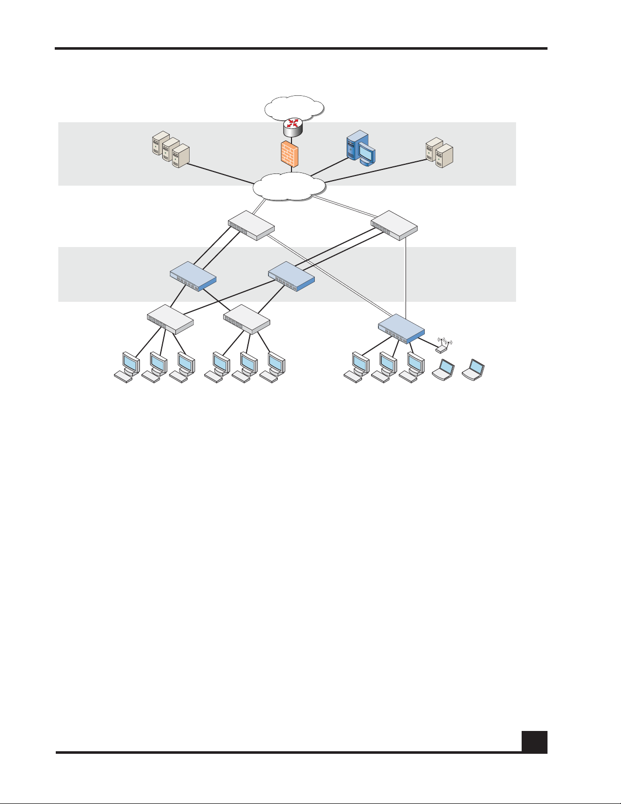
Figure 1 SafeGuard Controller and Switch in a Typical Deployment
With the preferred standard and typical deployment model, the SafeGuard Controller
device is a multi-port “bump-in-the-wire” device between the edge switch and the next
layer switch, whether that be the distribution layer or the core switch. The uplinks can
either be fiber or copper. A SafeGuard Switch is deployed like any other switch device,
but it can link directly to the distribution layer.
When deploying SafeGuard devices using this model, all SafeGuard OS features are
supported, including policy enforcement, captive portal, IP header validity, and malware
enforcement. Further, devices can be deployed without disrupting existing wiring closet
configurations. Figure 1 shows SafeGuard devices in the typical deployment model.
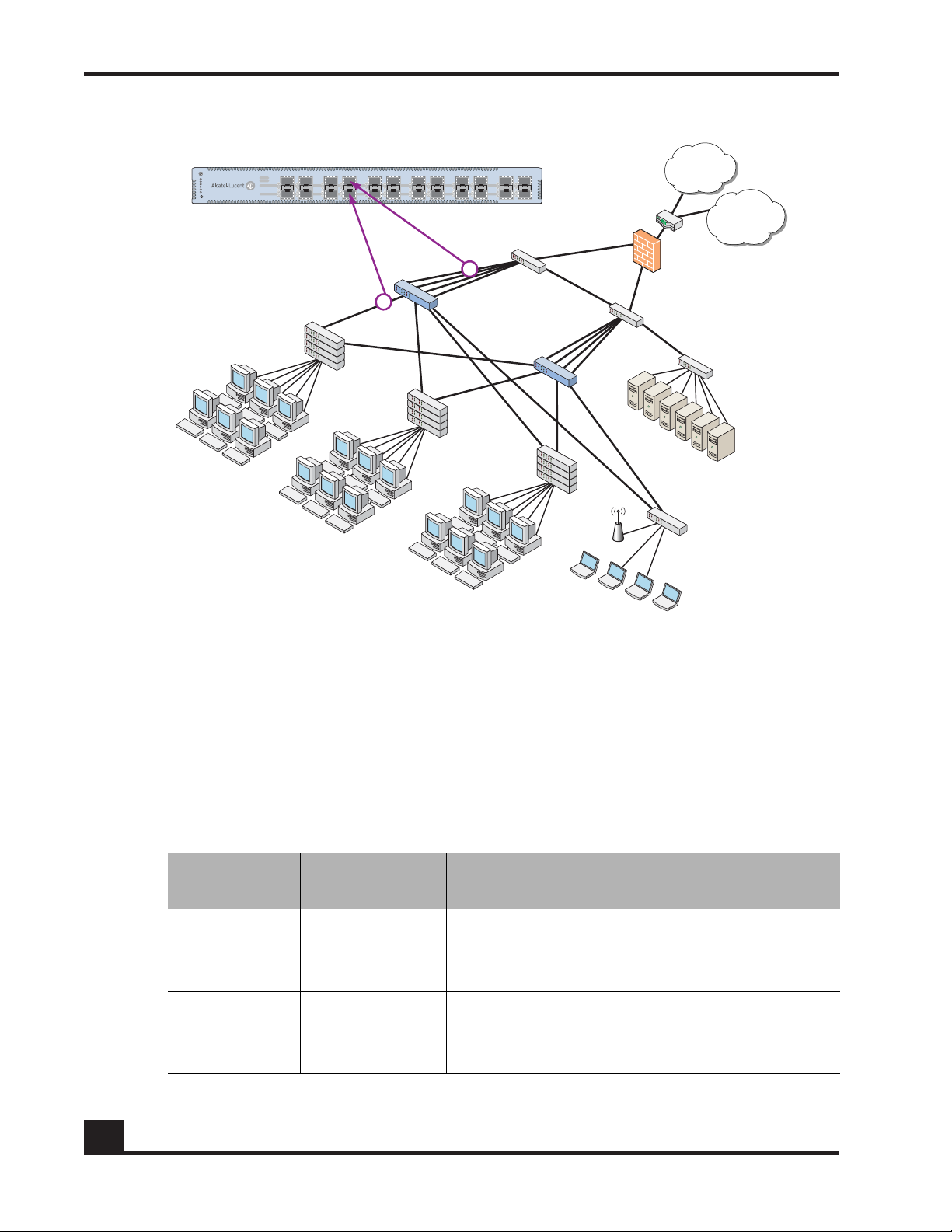
System recovery and high availability (HA) can be configured when deploying
SafeGuard Controllers. To, it requires an additional (redundant) SafeGuard Controller of
the same model, running the same software release, and configured with the same port
configuration.
In HA mode, the authentication state is propagated to the peer device before there is a
failure so that users do not have to re-authenticate. For example, end users do not need to
log in to the captive portal feature again if there is a system failure. Figure 2 shows this
type of deployment (for details on configuring high availability, see Configuring High
Availability Support on page 100).
OmniAccess SafeGuard OS Administration Guide
23
Page 24
Chapter 1: SafeGuard OS Overview
CST_011
Internet
WAN/VPN
Secure LAN
controller
Firewall
Core
switch
Active
directory
Data center
RADIUS
Executive
suite
1st floor
edge switch
[Marketing]
2nd floor
edge switch
[Operations]
3rd floor
edge switch
[Finance]
H
ost / edge
Network / core
Figure 2 High Availability (Redundant) SafeGuard Controller Deployment
Understanding Protection Modes
Ingress and egress data traffic is managed by SafeGuard devices based on the level of
protection mode set within the device. Based on the established protection mode—Pass-
thru mode, Monitor mode, or Protect mode. For details on setting protection modes, see
Changing the Protection Mode of Ports on page 95.
When Used SafeGuard Controller SafeGuard Switch
First time set up
and cabling
Testing and
trials
Table 3 Supported Protection Modes
Protection
Mode
Pass-thru
Mode
Monitor Mode
Acts as a transparent
bridge. All security
functionality is
bypassed.
Authentication, captive portal, visualization,
malware detection and protection and userbased policy checking is applied to all data
Acts as a standard L2/
L3 switch. All security
functionality is
bypassed.
traffic, but enforcement is ignored.
24
OmniAccess SafeGuard OS Administration Guide
Page 25

Table 3 Supported Protection Modes (continued)
Chapter 1: SafeGuard OS Overview
Protection
Mode
Protect Mode
When Used SafeGuard Controller SafeGuard Switch
Typical
Deployment
Authentication, captive portal, visualization,
malware detection and protection and userbased policy checking is applied to all data
traffic, and actively enforced.
OmniAccess SafeGuard OS Administration Guide
25
Page 26

User/Machine Authentication
■ Authentication via 802.1X or
MAC address
■ Passive Active Directory
authentication snooping
■ Passive RADIUS
authentication snooping
■ Captive portal
authentication
■ Trusted DHCP serve
Role Derivation
■ RADIUS attributes
■ Active Directory attributes
■ Physical location
■ Combination of above
Role-Based Policy (Access
Control By)
■ User group
■ Application
■ Select application attributes
■ Destination port
■ Resource (e.g. servers)
Host Posture Check
■ Dissolvable agent
■ Scan for known threats, anti-
virus definition, service
packs, and custom registry
keys and files
Enforcement Actions
■ Allow
■ Deny
■ TCP reset
■ Mirroring, logging
Threat Detection/Mitigation
■ Zero-hour threat detection
■ No signature updates
necessary
■ Drops malformed packets
■ Block by: physical port, SRC
MAC, offending application
Visualization
■ Ties usernames to
applications and security
violations
■ Identifies applications and
application content
■ Reports application details
to centralized policy center
Centralized Visualization
■ Ties into Alcatel-Lucent
OmniVista SafeGuard
Manager Command Center
■ User and application usage
repository
■ Real-time alert dashboard
■ Fully drillable forensics
capability
■ Reporting and scheduler
■ Full policy and role-
derivation configuration GUI
Logging and Reporting
■ Direct syslog reporting
■ Detailed security log
messages
■ Formatted for SIEM
integration
■ Formatted syslog to multiple
destinations
Management and Control
■ Industry-standard
Command Line Interface
(CLI)
■ Managed by Alcatel-Lucent
OmniVista SafeGuard
Manager Command Center
■ SNMP v1/v2
■ Telnet
■ SSH
■ TFTP
■ Standard and privileged
access modes
Administrator Authentication
■ RADIUS authentication
Performance (Switch Only)
■ Switching capacity: 101
million pps
■ Secure Switching Rate: 10
Gbps
Protocols (Switch Only)
■ 802.1D Bridging
■ 802.1D Spanning Tree
■ 802.1Q/p VLAN Tagging and
Priority
■ 802.1w Rapid Spanning Tree
■ 802.1S MSTP
■ 802.1X Port-based
authentication
■ 802.3 10Base-T
■ 802.3u 100Base-T
■ 802.3z 1000Base-SX/T
■ 802.3ae 10 Gbps Ethernet
■ 802.3af Power-over-Ethernet
Layer 2 Features (Switch Only)
■ 4,096 VLANs
■ 16,000 MAC Addresses
■ Protocol VLAN (802.1v)
■ Port Security (MAC address
locking)
■ Mirror/monitor ports
■ IGMP v1/v2 snooping
Layer 3 Features (Switch Only)
■ Static routing
■ Additional L3 capabilities
due in future software
releases
Chapter 1: SafeGuard OS Overview
SafeGuard OS Overall Feature Summary
The following table summarizes SafeGuard OS features supported by SafeGuard devices.
26
OmniAccess SafeGuard OS Administration Guide
Page 27

chapter
Accessing and
2
Managing the System
In this chapter:
■ Connecting to a SafeGuard Device Console
■ Accessing the SafeGuard Device Command Line Interface
■ Configuring Management Users
■ Managing Out-of-Band Management Port
■ Setting Up the System Time and Date (SNTP)
■ Managing Device Information
■ Managing Network Information
■ Configuring the Network Protocol
■ Configuring SNMP on the Device
■ Configuring Domain Name Servers
■ Resetting the Device
■ Configuring Data Traffic Ports
■ Configuring High Availability Support
Page 28

Chapter 2: Accessing and Managing the System
This chapter describes the tasks associated with managing the SafeGuard Controller or
the SafeGuard Switch as a device in the network.
Connecting to a SafeGuard Device Console
SafeGuard devices can be managed using a PC or laptop computer connected to the
SafeGuard Controller or SafeGuard Switch.
To connect a SafeGuard device console:
1 Using a null cable, connect a PC or laptop computer to the DCE port on the back
of the device.
2 Launch a terminal emulation program and configure the settings as shown in
Ta b le 4 .
3 The login prompt is displayed.
Table 4 PC Terminal Emulator Settings
PC or Laptop Setting
Emulation type vt100
Bits per second 9600
Data bits 8
Parity bits None
Stop bits 1
Flow control None
See the following sections for details on accessing the SafeGuard device command line
interface.
Accessing the SafeGuard Device Command Line Interface
The first time that you log into a SafeGuard device, use the default ‘Admin’ as a
username (and no [null] password). Upon first logging into the command interface, you
are in Non-Privileged mode. To perform management and configuration functions, you
need to be in Privileged mode.
28
To access Privileged mode, use the
enable command in Non-Privileged mode.
OmniAccess SafeGuard OS Administration Guide
Page 29

Chapter 2: Accessing and Managing the System
enable
This command has no parameters or variables.
For example:
(SafeGuardOS) #?
(SafeGuardOS) #enable
(SafeGuardOS) #
(SafeGuardOS) #configure terminal
(SafeGuardOS) (config) #
See the following sections for more details on accessing SafeGuard devices:
■ Using Telnet
■ Using Secure Shell (SSH)
■ Customizing and Working with the Command Line Interface Default Settings
Using Telnet
A SafeGuard device can be accessed via a Telnet session.
This section describes basic Telnet commands that may be useful when first accessing a
SafeGuard device via a Telnet session. See the following sections for more details:
■ Enabling and Disabling Telnet
■ Displaying the Current Telnet and Serial Port Connections
■ Closing a Telnet or SSH Session
■ Specifying the Maximum Number of Telnet Connections Allowed
■ Setting the Telnet Connection Session Timeout
Enabling and Disabling Telnet
Telnet access is enabled by default. If Telnet has been disabled, use the ip telnet
command in Privileged Exec mode. To disable Telnet, use the
ip telnet
no ip telnet
no form of the command.
The commands have no parameters or variables.
Displaying the Current Telnet and Serial Port Connections
To display the current Telnet and serial port connections, use the show sessions
command in Privileged Exec mode.
OmniAccess SafeGuard OS Administration Guide
29
Page 30

Chapter 2: Accessing and Managing the System
show sessions
An example of this output and explanation of the fields is described in Tracking an
Authenticated User Session on page 219.
Closing a Telnet or SSH Session
To close a Telnet or SSH session, use the disconnect command in Privileged Exec mode.
disconnect [sessionID | all]
Syntax Description sessionID Disconnects the session specified by the
all Disconnects all remote sessions.
The following example disconnects session ID 10:
session identifier. Use the show sessions
command to find the session ID.
(SafeGuardOS) # disconnect 10
(SafeGuardOS) #
Specifying the Maximum Number of Telnet Connections Allowed
To specify the maximum number of Telnet connection sessions that can be established,
use the ip telnet maxsessions command in Global Configuration mode. Use the
no
version of the command to restore the default value.
ip telnet maxsessions number
no ip telnet maxsessions
Syntax Description number Sets the number of Telnet sessions. Valid range
is from 1 to 5. The default value is 5.
The following example sets the number of Telnet sessions to 3:
(SafeGuardOS) # configure terminal
(SafeGuardOS) (config) # ip telnet maxsessions 3
(SafeGuardOS) (config) #
Setting the Telnet Connection Session Timeout
30
To set the Telnet connection session timeout value (in minutes), use the ip telnet timeout
command in Global Configuration mode. Use the
no version of the command to restore
the default value.
ip telnet timeout timeout
OmniAccess SafeGuard OS Administration Guide
Page 31

no ip telnet timeout
Syntax Description timeout Sets the number of minutes that a session can
The following example sets the Telnet connection timer to never expire:
(SafeGuardOS)# configure terminal
(SafeGuardOS) (config) # ip telnet timeout 0
(SafeGuardOS) (config) #
Using Secure Shell (SSH)
Like Telnet, Secure Shell (SSH) is a protocol that allows the logging into of another
computer over a network to execute commands in a remote machine, and to move files
from one machine to another. Unlike Telnet that sends text in a clear text format, however,
SSH encrypts the connection session.
Chapter 2: Accessing and Managing the System
be idle. Valid range is a decimal value from 0
to 160. A value of 0 indicates that the session
remains active indefinitely. The default value is
5.
SSH provides more security fo
r remote connections than Telnet by providing strong
encryption when a device is authenticated. The SafeGuard OS supports:
■ SSH version 1 (SSHv1)
■ SSH version 2 (SSHv2)
■ Rivest, Shamir and Adleman (RSA) keys, versions 1 and 2
■ Digital Signature Standard (DSA) keys
■ A maximum of 5 SSH sessions
NOTE: SafeGuard OS does not support SSH passwords or passkeys.
This section describes basic SSH commands that may be useful when first accessing a
SafeGuard device via a SSH session.
See the following sections:
■ Enabling an SSH Session
■ Downloading SSH Key Files from TFTP Server
■ Generating DSA, RSA, RSA Keys
■ Deleting DSA, RSA, RSA Keys
OmniAccess SafeGuard OS Administration Guide
31
Page 32

Chapter 2: Accessing and Managing the System
■ Changing SSH Protocols
■ Limiting SSH Sessions
■ Setting the SSH Timer
■ Displaying SSH Configuration Information
Enabling an SSH Session
To enable an SSH session on the device:
1 Enable SSH on the device by entering the ip ssh command in Global
Configuration mode. The no version of the command disables SSH, which is the
default state.
ip ssh
no ip ssh
The commands have no parameters or variables. The first time that SSH is
enabled on a device, SafeGuard OS detects that keys are not present and generates
the keys automatically.
(SafeGuardOS) #configure terminal
(SafeGuardOS) (config) #ip ssh
(SafeGuardOS) (config) #exit
(SafeGuardOS) #
2 Verify the configuration using the show ip ssh command.
Downloading SSH Key Files from TFTP Server
T o download private key files from a T rivial File T ransfer Protocol (TFTP) server for SSH (that do
not contain passkeys), use the Privileged Exec copy command to download a key file.
NOTE: If you want to TFTP your own keys instead of having them generated
by the SafeGuard device, you must TFTP all three types of keys (DSA, RSA1,
AND RSA). All three keys are required for proper SSH functionality.
copy tftp://ip/{filepath/}file nvram:[sshkey-dsa |sshkey-rsa1 |sshkey-
rsa]
Syntax Description ip IP address of the TFTP server
filepath (Optional) Directory path to the file.
32
file Filename of the key file.
nvram:sshkey-dsa Specifies to download a SSH DSA key
file.
OmniAccess SafeGuard OS Administration Guide
Page 33

Chapter 2: Accessing and Managing the System
nvram:sshkey-rsa1 Specifies to download a SSH RSA1 key
file.
nvram:sshkey-rsa Specifies to download a SSH RSA2 key
file.
The following example specifies how to download an SSH RSA1 key file from the TFTP server:
(SafeGuardOS) # copy tftp://180.29.52.20/keys nvram:sshkey-rsa1
(SafeGuardOS) #
Generating DSA, RSA, RSA Keys
The first time that SSH is enabled, the SafeGuard OS generates keys for DSA, RSA and
RSA1 which are not installed. The key deciphers the SSH encryption. To generate new
SSH keys, in Global Configuration mode use the ip ssh key generate command.
NOTE: In order to be in export compliance, the SafeGuard OS generates keys
that are just 56-bits in length. If you need a key that is larger than this, create
the key externally.
ip ssh key generate key
Syntax Description key Key to generate. Valid entries are:
■ DSA
■ RSA
■ RSA1
■ all
Specifying all generates all SSH keys.
If key is not specified, the command
generates any keys not currently installed.
The following example generates all SSH keys:
(SafeGuardOS) #configure terminal
(SafeGuardOS) (config) #ip ssh key generate all
(SafeGuardOS) (config) #exit
(SafeGuardOS) #
Deleting DSA, RSA, RSA Keys
To delete all installed SSH keys, in Global Configuration mode enter the ip ssh key delete
command. The command has no parameters or variables.
The following example deletes all installed keys:
OmniAccess SafeGuard OS Administration Guide
33
Page 34

Chapter 2: Accessing and Managing the System
(SafeGuardOS) #configure terminal
(SafeGuardOS) (config) #ip ssh key delete
(SafeGuardOS) (config) #exit
(SafeGuardOS) #
Changing SSH Protocols
By default, SafeGuard OS supports both SSH versions 1 and 2. The protocols can be
deleted or added as necessary by explicitly defining one or both. Use the ip ssh protocol
command in Global Configuration mode to change the protocol support.
ip ssh protocol protocol_level {protocol_level}
Syntax Description protocol_level Specifies one or both SSH protocols. Valid
entries are:
■ 1 – SSH version 1
■ 2 – SSH version 2
■ 1 2 – for both
The following example limits the SSH protocol to SSH version 2:
(SafeGuardOS) #configure terminal
(SafeGuardOS) (config) #ip ssh protocol 2
(SafeGuardOS) (config) #exit
(SafeGuardOS) #
Limiting SSH Sessions
The default for SSH sessions is set to the maximum of 5 sessions. To reduce the number of
sessions, in Global Configuration mode use the ip ssh maxsessions command.
ip ssh maxsessions sessions
Syntax Description sessions Specifies the maximum number of SSH
sessions allowed. Valid entries are 1 to 5.
The following example limits the SSH sessions to 3:
(SafeGuardOS) #configure terminal
(SafeGuardOS) (config) #ip ssh maxsessions 3
(SafeGuardOS) (config) #exit
(SafeGuardOS) #
34
OmniAccess SafeGuard OS Administration Guide
Page 35

Chapter 2: Accessing and Managing the System
Setting the SSH Timer
SSH connections time out at 5 minutes, by default. To change the timeout timer from 1 to
160 minutes, in Global Configuration mode use the ip ssh timeout command.
NOTE: A session is active as long as the session is idle for the value set.
Changing the timeout value for active sessions does not become effective until
the session is re-accessed. Also, any keystroke activates the new timeout
duration.
ip ssh timeout minutes
Syntax Description minutes Specifies the connection timer in minutes.
Valid entries are 1 to 160.
The following example limits the idle time for SSH connections to 20 minutes:
(SafeGuardOS) #configure terminal
(SafeGuardOS) (config) #ip ssh timeout 20
(SafeGuardOS) (config) #exit
(SafeGuardOS) #
Displaying SSH Configuration Information
To display the current SSH configuration, use the show ip ssh command in Privileged
Exec mode:
show ip ssh
The command has no parameters or variables.
The following example is representative of the command output:
(SafeGuardOS) #show ip ssh
SSH Configuration
Administrative Mode: .......................... Enabled
Operational Mode: ............................. Enabled
Protocol Levels: .............................. Versions 1 and 2
SSH Sessions Currently Active: ................ 0
Max SSH Sessions Allowed: ..................... 2
SSH Timeout: .................................. 4
SSH Keys Installed: ........................... RSA1 RSA DSA
(SafeGuardOS) #
OmniAccess SafeGuard OS Administration Guide
35
Page 36

Chapter 2: Accessing and Managing the System
The fields in the output represent:
Display Description
Administrative Mode
Displays
been enabled or disabled
Operational Mode Displays the operational status of SSH and indicates
whether SSH is currently enabled or disabled.
Protocol Levels
Displays
whether the administrative state of SSH has
.
the protocol level. This field may have the
values of version 1, version 2 or both versions 1 and
version 2
SSH Sessions Currently
Active
Max SSH Sessions Allowed
Displays the
connections
Displays the
allowed
SSH Timeout Displays the idle timer for connection time. This field can
be from 1 to 160 minutes.
SSH Keys Installed Displays which keys are currently installed. Possible keys
are: RSA1, RSA and DSA.
.
number currently active SSH
. This field can be from 0 to 5.
maximum number of SSH connections
. This field can be from 0 to 5. The default is 5.
Customizing and Working with the Command Line Interface Default Settings
36
See the following sections for details on how to customize the command line interface
default settings:
■ Changing the System Command Prompt
■ Setting a Maximum Serial Console Connect Time
■ Enabling and Disabling CLI Display Paging
■ Uploading a New CLI Banner File
■ Uploading the CLI Log File
■ Copying the System Diagnostics File
■ Copying the System Debug File
■ Displaying the Current HTTP Information
OmniAccess SafeGuard OS Administration Guide
Page 37

Chapter 2: Accessing and Managing the System
Changing the System Command Prompt
To change the command line interface prompt, use the set prompt command in enable
mode. The length of the prompt can be up to 64 alphanumeric characters.
set prompt string
Syntax Description string Sets the command prompt to an
alphanumeric string up to 64 characters and
numbers. The prompt is case sensitive
The following example sets the command prompt to OmniAccess 2400 SafeGuard:
(SafeGuardOS) # set prompt OmniAccess 2400 SafeGuard
(OmniAccess 2400 SafeGuard) #
Setting a Maximum Serial Console Connect Time
To set a maximum connect time (in minutes) without console activity for the serial
console, use the serial timeout command in Line Configuration submode. Line
Configuration Mode is entered by using the lineconfig command in Global
Configuration mode.
serial timeout time
Syntax Description time Sets the number of minutes that a serial
console can be idle. Valid range is a decimal
value from 0 to 160. A value of 0 indicates that
the console remains active indefinitely. The
default value is 5.
The following example sets the console timeout to 10 minutes:
(SafeGuardOS) # configure terminal
(SafeGuardOS) (config) # lineconfig
(SafeGuardOS) (line) # serial timeout 10
(SafeGuardOS) (line) #
Enabling and Disabling CLI Display Paging
To enable or disable CLI display paging, use the paging command in Privileged Exec
mode.
paging [enable | disable]
Syntax Description enable Enable CLI display paging mode.
disable Disable CLI display paging mode.
OmniAccess SafeGuard OS Administration Guide
37
Page 38

Chapter 2: Accessing and Managing the System
The following example disables CLI display paging:
(SafeGuardOS)# paging disable
(SafeGuardOS)#
Uploading a New CLI Banner File
To upload the CLI banner file, use the copy nvram:clibanner command in Global
Configuration mode.
copy nvram:clibanner
Syntax Description ip Specifies the IP address of the TFTP server.
tftp://ip/{filepath/}filename
filepath (Optional) Specifies the directory path to the file.
filename Specifies the filename of the file being saved.
Uploading the CLI Log File
To upload the log file, use the copy nvram:log command in Global Configuration mode.
copy nvram:log
Syntax Description ip Specifies the IP address of the TFTP server.
tftp://ip/{filepath/}filename
filepath (Optional) Specifies the directory path to the file.
filename Specifies the filename of the file being saved.
Copying the System Diagnostics File
38
To copy a system diagnostics file, use the copy system:diag-info command in Global
Configuration mode.
copy system:diag-info
Syntax Description ip Specifies the IP address of the TFTP server.
tftp://ip/{filepath/}filename
filepath (Optional) Specifies the directory path to the file.
filename Specifies the filename of the file being saved.
OmniAccess SafeGuard OS Administration Guide
Page 39

Chapter 2: Accessing and Managing the System
Copying the System Debug File
To copy a system debug file, use the copy system:dump command in Global
Configuration mode.
copy system:dump
Syntax Description ip Specifies the IP address of the TFTP server.
://ip/{filepath/}filename
filepath (Optional) Specifies the directory path to the file.
filename Specifies the filename of the file being saved.
Displaying the Current HTTP Information
To display the current HTTP information, use the show ip http command in Privileged
Exec mode.
show ip http
This command has no parameters or variables.
Exiting or Logging Out of a Command Line Session
To exit or log out of a command level session, use either the exit or logout command in
any mode.
exit
logout
The command has no options or parameters. For example:
(SafeGuardOS) # logout
Configuring Management Users
The Admin user has full access to all CLI both from the front-panel ports and from the
rear-panel management port.
■ Management Users – A management user can be defined as having three levels of
authority:
— Admin-user has full access to all commands.
— Privilege-user has permission to execute action, clear and configure
commands, with the exception of the user management commands.
—Exec-user has access to limited commands.
OmniAccess SafeGuard OS Administration Guide
39
Page 40

Chapter 2: Accessing and Managing the System
■ Network Users – Network users are end-users defined in the SafeGuard local
authentication database. Network users do not have authority to execute
commands at the command line. For more information on managing network
users, see Maintaining Users on page 258.
This section describes setting up administrator and network user access to SafeGuard
devices. By default, an “Admin” user is configured with the initial configuration. See the
following sections for more details:
■ Configuring Management Users
■ Assigning a Login List to the Default Login User
■ Configuring RADIUS Users for Management Users
■ Clearing All Passwords
For more information on managing network users, see Maintaining Users on page 258.
Configuring Management Users
This section describes adding and changing management accounts. See the following
sections for more details:
■ Adding Management Users to the Database
■ Displaying the Management Users
■ Setting a Password for the Default Admin Account
■ Configuring Local Authentication for Management Users
Adding Management Users to the Database
Management users are the administrators who will be logging in from the service/front
panel port and manage SafeGuard. To add a management user to the database, in the
Global Configuration mode use the
To remove a management user use the
aaa mgmt-user username passwd password access-mode mode
no aaa mgmt-user username
Syntax Description username The name of the user being added to
aaa mgmt-user command.
no form of the command.
the database. User names can be up
to 31 characters long.
40
password The login password. Login passwords
can be up to 31 characters long.
OmniAccess SafeGuard OS Administration Guide
Page 41

Chapter 2: Accessing and Managing the System
mode The mode from highest to lowest
privileges are:
■ admin-user – An admin user is
allowed to access all commands.
■ priv-user – The privilege user is
allowed to access only show and
action commands.
■ exec-user – The exec user is
allowed to access only show
commands.
The following example adds a management user with username abcd, password abcd
and access mode exec-user:
(SafeGuardOS) (config) #no aaa mgmt-user abcd passwd abcd access-mode exec-user
The following example deletes the management user with username abcd:
(SafeGuardOS) (config) #no aaa mgmt-user abcd
The following example changes the password of an administrator user (mgmtuser) to
f00onU3.
(SafeGuardOS) (config) # aaa mgmt-user mgmtuser passwd f00onU3
When a password is changed, a prompt asks for the former password. If none exists,
press the Enter key. The passwords are stored in encrypted format for protection.
The system contains a default “Admin” administrator user that cannot be deleted. The
default administrative password (set to null by default), however, can be changed and
encrypted.
Displaying the Management Users
To display the management users, in the Global Configuration mode use the show aaa
mgmt-users
show aaa mgmt-users
The command has no parameters.
The following example shows sample output from the
(SafeGuardOS) #show aaa mgmt-users
command.
show aaa mgmt-users command:
SNMPv3 SNMPv3 SNMPv3
User Name User Access Mode Access Mode Authentication Encryption
---------- ---------------- ----------- -------------- ----------
admin Admin Read/Write None None
guest Exec Read Only None None
execuser Exec Read Only None None
admin1 Admin Read Only None None
OmniAccess SafeGuard OS Administration Guide
41
Page 42

Chapter 2: Accessing and Managing the System
abcd Exec Read Only None None
priv-user Exec Read Only None None
(SafeGuardOS) #
NOTE: SafeGuard OS will support SNMPv3 will be supported in a future
release.
The fields in the output represent:
Field Description
User Name Username as detected by its authentication.
User Access Mode The user’s access mode.
SNMPv3 Access Mode The SNMPv3 access mode.
SNMPv3 Authentication Whether the user has SNMPv3 authentication.
SNMPv3 Encryption Whether the user has SNMPv3 Encryption.
Setting a Password for the Default Admin Account
To set the password for the default administrator (admin) account, use the aaa mgmt-
user passwd admin
is enabled, the password must be at least eight alphanumeric characters in length.
The username and password are not case sensitive. When a password is changed, a
prompt asks for the former password. If none exists, press the Enter key. Use the no
version of the command to set the password to blank.
aaa mgmt-user passwd admin passwd
no aaa mgmt-user passwd admin passwd
Syntax Description passwd Specifies the new password.
The following example sets the default password to f00onU2:
(SafeGuardOS) #configure terminal
(SafeGuardOS) (config) #aaa mgmt-user passwd admin f00onU2
Password Changed!
(SafeGuardOS) (config) #exit
(SafeGuardOS) #
command. If a user is authorized for authentication or encryption
42
OmniAccess SafeGuard OS Administration Guide
Page 43

Chapter 2: Accessing and Managing the System
Configuring Local Authentication for Management Users
Users are set up in the authentication database by assigning them to a set of roles usually
defined by group and then by mapping a set of authentication protocol-specific attributes
and their values to a role. The attributes are first obtained by user authentication against
the local authentication database. If the user does not authenticate against the local
database, you can configure the user to authenticate against a centralized RADIUS
database as a backup.
Creating Authentication Lists
In most instances, users are assigned roles based on their group or job responsibilities. To
identify those groups of users, you need to create a list for each distinct user group.
Use the aaa mgmt-user authentication login command in Global Configuration mode to
create a user group or organizational list.
aaa mgmt-user authentication login listname {methods}
Syntax Description listname The name of the list being created. A list
name can be up to 15 characters long.
methods One or more authentication methods used to
authenticate this group of users. You may
specify up to 3 non-repeating methods. If not
specified, the system uses the default-list. If
less than 3 methods are specified, the
remaining methods are classified as
undefined. Specify the method in the order
of precedence you want to run. Valid values
for methods are:
■ local – Use local authentication.
■ RADIUS – Use remote RADIUS
authentication.
■ Reject – Deny the user.
The following example creates an authentication list for a group of sales people. The
group uses local authentication as the only authentication method and users who are
unable to authenticate using that method are denied access to the network:
(SafeGuardOS) #configure terminal
(SafeGuardOS) (config) #aaa mgmt-user authentication login salesList local
reject
(SafeGuardOS) (config) #exit
(SafeGuardOS) #
Displaying the Authentication Login List
To verify the contents and methods being used for authentication, use the show aaa
mgmt-users authentication-list command in Privileged Exec mode:
OmniAccess SafeGuard OS Administration Guide
43
Page 44

Chapter 2: Accessing and Managing the System
show aaa mgmt-users authentication list
This command has no options or parameters. The following is sample output from the
command:
Authentication Login List Method 1 Method 2 Method 3
------------------------- -------- -------- --------
defaultList local undefined undefined
list123 reject undefined undefined
authLoginList radius local reject
radius-list radius local reject
salesList radius local reject
The fields of the output represent:
Field Description
Authentication Login The name of the authentication login list.
Method 1 The primary method of authentication.
Method 2 This method of authentication is used if the primary
method is unavailable. If a secondary method is not
used, this field is undefined.
Method 3 This method of authentication is used if the secondary
method is unavailable. If a secondary method is not
used, this field is undefined.
Assigning a Login List to the Default Login User
To ensure that any non-configured users who attempt to log into the management port
are forced to authenticate against the RADIUS server, use the
defaultlogin
authentication, use the
aaa mgmt-user defaultlogin listname
no aaa mgmt-user defaultlogin
Syntax Description listname Name of the authentication list or group name
command in the Global Configuration mode. To disable RADIUS
no version of the command.
listname
being authenticated.
aaa mgmt-user
44
The following example assigns salesList to the defaultLogin list:
(SafeGuardOS) #configure terminal
(SafeGuardOS) (config) #aaa mgmt-user defaultlogin salesList
(SafeGuardOS) (config) #exit
(SafeGuardOS) #
OmniAccess SafeGuard OS Administration Guide
Page 45

Chapter 2: Accessing and Managing the System
The following example shows the disabling RADIUS authentication of non-configured
users:
(SafeGuardOS) (config) # no aaa mgmt-user defaultlogin salesList
(SafeGuardOS) (config) #
Configuring RADIUS Users for Management Users
In order to provide administrative privileges to remote RADIUS users, the Service-Type
field in RADIUS must be configured to return the appropriate value. Configure the
RADIUS server to return Service-Type = 1 or Login
NAS Prompt for exec-user. For FreeRadius, Service-Type = NAS-Prompt-User and
Service-Type = Login-User.
Different implementations of RADIUS might have slight variations on how to set this
field. See Ta b le 5 for some examples of this field, and see your RADIUS product
documentation for further help.
for priv-user, Service-Type = 7 or
Table 5 RADIUS Service-Type Settings
Implementation Service-Type
FreeRADIUS 6 or Administrative-User
Microsoft IAS Administrative
SteelBelt RADIUS Administrative
In the following example, MyCompany uses FreeRADIUS. Users Moe and Larry are
setup for administrative privileges while user Curley logs in as priv-user has most of the
privileges of the administrative user.
Moe Auth-Type:=System
Service-Type=6
Login-Service=Telnet
Larry Auth-Type:=System
Service-Type=Administrative-User
Login-Service=Telnet
Curley Auth-Type:=System
Service-Type=Login-User
Login-Service=Telnet
Alcatel-Lucent-Role=”Curley-Alcatel-LucentVSA”
OmniAccess SafeGuard OS Administration Guide
45
Page 46

Chapter 2: Accessing and Managing the System
Clearing All Passwords
To clear all user passwords and reset them to the factory defaults (null) without powering
off the device, use the clear pass command in Privileged Exec mode. When prompted to
confirm that the password reset should proceed, enter y for Yes.
clear pass
The following example clears all user passwords and reinstates the system defaults:
(SafeGuardOS) #clear pass
Are you sure you want to reset all passwords? <n/y> y
Passwords reset
(SafeGuardOS) #
Managing Out-of-Band Management Port
This section describes the tasks and commands used for configuring and displaying
information for the out-of-band management port on SafeGuard devices. The
management port is also referred to as the service port.
See the following sections for more details:
■ Setting the IP Configuration Protocol
■ Enabling or Disabling the Management Port
■ Setting Speed and Duplex for the Management Port
■ Displaying Configuration Information for the Management Port
Setting the IP Configuration Protocol
To set the configuration protocol for the management port, use the serviceport protocol
command in Global Configuration mode.
When using this command, it is suggested to run the command twice: once with the
none, and once with the value desired for the management port’s protocol support
value
(either
For more details on bootstrap and DHCP protocols, see Configuring Bootstrap or DHCP
Relay on page 194.
serviceport protocol [none | bootp | dhcp]
bootp or dhcp). When modified, the change takes effect immediately.
46
Syntax Description none Specifies no protocol.
bootp Specifies BOOTP as the protocol.
OmniAccess SafeGuard OS Administration Guide
Page 47

Chapter 2: Accessing and Managing the System
dhcp (Default) Specifies DHCP as the protocol.
The following command example changes the protocol to bootstrap:
(SafeGuardOS) # configure terminal
(SafeGuardOS) (config) # service protocol none
(SafeGuardOS) (config) # service protocol bootp
(SafeGuardOS) (config) #
Setting the IP Address, Netmask, and Gateway of the System
To set the IP address, netmask, and gateway of the management port, use the serviceport
ip command in Global Configuration mode. Before running this command, however, the
service port protocol must be set to
page 46).
serviceport ip ipaddr netmask [gateway]
none first (see Setting the IP Configuration Protocol on
Syntax Description ipaddr IP address for the service port.
netmask Network mask for the service port.
gateway Optional for Controller only. Gateway IP
address. (To set the default gateway on the
Switch, use ip route.)
The following example sets the service port configuration:
(SafeGuardOS) # configure terminal
(SafeGuardOS) (config) # serviceport protocol none
(SafeGuardOS) (config) # serviceport ip 172.68.15.1 255.255.0.0
(SafeGuardOS) (config) #
Enabling or Disabling the Management Port
The management port is enabled, by default, and so therefore is not explicitly displayed
in the show running-config command output. The serviceport enable command enables
the PHY and lights the management port link LED. The no version of the command
disables the PHY and extinguishes the management port link LED. The Global
Configuration commands use the following syntax:
serviceport enable
no serviceport enable
The commands have no parameters or variables.
OmniAccess SafeGuard OS Administration Guide
47
Page 48

Chapter 2: Accessing and Managing the System
Setting Speed and Duplex for the Management Port
The management port can operate at a variety of speeds and duplex settings. The default
settings are to auto-negotiate with the link partner. For auto-negotiation to succeed, the
management port and the link partner must both be set for auto-negotiating. Otherwise,
the management port attempts to auto-negotiate but could fail if traffic does not match
the auto-negotiated speed.
Use the serviceport speed command in Global Configuration mode to override the autonegotiation and set the speed and duplex for the management port using the following
syntax:
serviceport speed [10 | 100] [full-duplex | half-duplex]
Syntax Description 10 Specifies running the management port
at 10 Mbps.
100 Specifies running the management port
at 100 Mbps.
half-duplex Specifies half duplex; transmitting and
receiving data one direction at a time.
full-duplex Specifies full duplex; transmitting and
receiving data at the same time.
The following example forces the management port to run at 100 Mbps half-duplex.
(SafeGuardOS) # configure terminal
(SafeGuardOS) (config) # serviceport speed 100 half-duplex
(SafeGuardOS) (config) # exit
Use the show serviceport command in Privileged Exec mode to verify the configuration.
See Displaying Configuration Information for the Management Port on page 48.
Use the serviceport auto-negotiate command in Global Configuration mode to override
the speed and duplex settings on the management port. The no version of the command
disables auto-negotiation.
serviceport auto-negotiate
no serviceport auto-negotiate
Displaying Configuration Information for the Management Port
48
To display service port configuration information, use the show serviceport command in
Privileged Exec mode. For example:
show serviceport
OmniAccess SafeGuard OS Administration Guide
Page 49

Chapter 2: Accessing and Managing the System
The command has no options or parameters.
The following output is representative of the show serviceport command on a SafeGuard
Switch. This command’s output on a SafeGuard Controller would be similar, but with the
addition of “Gateway Address” following the “Subnet Mask” line:
(SafeGuardOS) #show serviceport
Current ServicePort IP configuration
IP Address..................................... 172.16.1.10
Subnet Mask.................................... 255.255.192.0
ServPort Configured Protocol Current........... None
Burned In MAC Address.......................... 00:12:36:FE:92:CE
ServicePort Link Status........................ Up
ServicePort Admin Status....................... Enabled
Configured ServicePort speed................... auto-negotiate
ServicePort Duplex Status...................... 100M FULL
ServicePort Statistics
Total Packets Received ........................ 110
Total Packets Transmitted ..................... 46
Total Bytes Received........................... 9784
Total Bytes Transmitted........................ 4166
Total Bad Packets Received..................... 0
Total Packet Transmit Problems................. 0
No Receive Space in Buffers.................... 0
No Transmit Space in Buffers................... 0
Multicast Packets Received ................... 0
Total Collisions............................... 0
ServicePort Detailed Rx Statistics
Packet Length Errors........................... 0
Ring Buffer Overflow Errors.................... 0
CRC Errors..................................... 0
Frame Alignment Errors......................... 0
Fifo Overrun Errors............................ 0
Missed Errors.................................. 0
ServicePort Detailed Tx Statistics
Aborted Errors................................. 0
Carrier Errors................................. 0
Fifo Overrun Errors............................ 0
Heartbeat Errors............................... 0
Window Errors.................................. 0
The fields in the output represent:
Field Description
Current service Port IP configuration
IP address IP address of the interface.
Subnet Mask IP subnet mask for this inte rfa ce .
OmniAccess SafeGuard OS Administration Guide
49
Page 50

Chapter 2: Accessing and Managing the System
Field Description
ServPort Configured
Protocol Current
Service Port Statistics
Total Packets Received Total number of packets (including broadcast packets
Total Packets Transmitted Total number of packets that were transmitted from the
Total Bytes Received
Network protocol that is currently being used, if any.
and multicast packets) that were received by the
management port.
management port.
Total number of octets of data (including those in
bad packets) received on the port.
Total Bytes Transmitted
Total number of octets of data (including those in
bad packets) transmitted from the port.
Total Bad Packets
Received
Total Packet Transmit
Problems
No Receive Space in
Buffers
No Transmit Space in
Buffers
Total number of bad packets received on the port.
Total number of bad packets transmitted from the
port.
0
0
Multicast Packets
Received
Total Collisions 0
Service Port Detailed Rx Statistics
Packet Length Errors 0
Ring Buffer Overflow Errors 0
CRC Errors 0
Frame Alignment Errors 0
Fifo Overrun Errors 0
Missed Errors 0
Service Port Detailed Tx Statistics
Aborted Errors 0
Carrier Errors 0
Fifo Overrun Errors 0
0
50
OmniAccess SafeGuard OS Administration Guide
Page 51

Chapter 2: Accessing and Managing the System
Field Description
Heartbeat Errors 0
Window Errors 0
Displaying Address Resolution Protocol Information
SafeGuard Controllers have a preset configuration for the address resolution protocol
(ARP) table and the ARP cache. SafeGuard Switches allow modification of the ARP
settings. For details on configuring ARP on the SafeGuard Switch, see Configuring Address
Resolution Protocol on page 184. To display ARP information, see Displaying ARP
Information on page 189
Setting Up the System Time and Date (SNTP)
If a Simple Network Time Protocol (SNTP) server is used to synchronize time settings in
the network, it is not necessary to manually configure clock settings for the SafeGuard
device(s). SNTP setup is discussed in Configuring SNTP on page 54.
See the following sections for more details:
■ Manually Setting the Time and Date
■ Configuring SNTP
■ Optional SNTP Client Configurations
Manually Setting the Time and Date
SafeGuard devices have an on-board real-time clock. The following settings can be
manually adjusted:
■ Timezone setting. Setting the timezone is a recommended step during product
installation.
■ Automatic changeover for daylight savings settings
■ Software system clock settings
NOTE: The order in which clock settings are configured can affect the
accuracy of the time setting.
To manually configure the time and date on the device:
1 Set the timezone. Skip this step if the timezone was set up during installation.
OmniAccess SafeGuard OS Administration Guide
51
Page 52

Chapter 2: Accessing and Managing the System
To set the device to the correct timezone, use the clock timezone command in
either Privileged Exec or Global Configuration modes.
clock timezone zonename hours_offset {minutes_offset}
Syntax Description zonename Specifies an arbitrary name of the
The following example sets the timezone to Pacific Standard Time (PST).
timezone in a
3-letter abbreviation. For example,
Eastern Standard Time is entered
as EST.
hours_offset Specifies the number of hours
difference from Universal Time
(a.k.a. Greenwich Mean Time,
GMT). Valid entries are -23 to 23.
minutes_offset (Optional) Specifies the number of
minutes offset from Universal Time.
(SafeGuardOS) # clock timezone PST -8
(SafeGuardOS) #
2 Set the time and date.
If no other time sources are available to set the current time and date, use the set
clock command in Privileged Exec mode. The time specified in this command is
relative to Universal Time Clock (UTC) time zone. The system can then be
synchronized to an external Network Time Protocol (NTP) clock source.
This command also updates the real time clock chip so it is preserved across
reboots.
clock set time month day year
Syntax Description time Time using 24 hour format
(military).
month Month abbreviated to 3
characters, for example, Jan for
January or Jun for June.
day Date in the month, for example, 29
for October 29th.
52
year 4-digit year, for example, 2006.
The following example sets the time to November 29, 2007 at 4:25:37 PM:
(SafeGuardOS) # clock set 16:25:37 NOV 29 2007
(SafeGuardOS) #
OmniAccess SafeGuard OS Administration Guide
Page 53

Chapter 2: Accessing and Managing the System
3 Set up Daylight Savings Time.
In many countries, clocks are set back an hour in the Summer when the days
become longer. Often referred to as Daylight Savings Time, system clocks must be
reset for this seasonal adjustment. Use the clock summer-time command in
Global Configuration modes to adjust for this seasonal change.
clock summer-time zonename [recurring | startweek startday
startmonth starttime endweek endday endmonth endtime
Syntax Description zonename An arbitrary name of the timezone
in a 3-letter abbreviation. For
example, Eastern Standard Time is
entered as EST.
recurring Indicates that the change
happens every year.
If this option is used, the system
uses the United States Daylight
Savings Time rules as enacted by
the Uniform Time Act amended in
1986.
In the European Union, Daylight
Saving Time starts at slightly
different times of the year and
need to be manually entered.
]
startweek Week in the month to make the
time change. Valid values are 1 to
5 or last.
startday Day of the week to make the time
change. Valid values are Monday
through Sunday.
startmonth Month to start the time change.
Valid values are January though
December.
starttime Hour to make the change. The
format is hh:mm.
endweek Week in the month to change the
time back. Valid values are 1 to 5
or last.
endday Day of the week to change the
time back. Valid values are
Monday through Sunday.
endmonth Month to change the time back.
Valid values are January though
December.
OmniAccess SafeGuard OS Administration Guide
53
Page 54

Chapter 2: Accessing and Managing the System
The following example, configures Summer hours as a recurring event.
(SafeGuardOS) # configure terminal
(SafeGuardOS) (config) # clock summertime recurring
(SafeGuardOS) (config) # exit
4 To display the system time, use the show clock command in Privileged Exec
mode using the following syntax:
show clock
The command has no parameters or variables.
Configuring SNTP
Simple Network Time Protocol (SNTP) is an adaptation of the Network Time Protocol
(NTP) used to synchronize computer clocks across the Internet. For a stand-alone system
that sets and synchronizes the time for the network, configure SNTP on the SafeGuard
device.
endtime Hour to change the time back.
The format is hh:mm.
To configure SNTP:
1 Designate a SNTP server using the sntp server command in Global Configuration
mode. Up to 3 SNTP servers can be configured.
sntp server ipaddr {priority {version {portid}}}
Syntax Description ipaddr Specifies the poll interval for SNTP
unicast clients in seconds as a
power of two. Valid values are 6 to
30 seconds.
priority (Optional) Ranks or prioritizes the
server among other servers. Up to 3
SNTP servers may be specified.
Valid values are 1 to 3.
version (Optional) Specifies the version of
SNTP. Valid values are 1 to 4.
portid (Optional) Specifies the port
identification number. Valid values
are 1 to 65535.
The following example configures an SNTP server running SNTPv4 on port ID 25.
54
(SafeGuardOS) # configure terminal
(SafeGuardOS) (config) # sntp server 172.82.45.23
OmniAccess SafeGuard OS Administration Guide
Page 55

Chapter 2: Accessing and Managing the System
(SafeGuardOS) (config) # exit
(SafeGuardOS) #
To delete this server, use the no version of the command.
2 Validate the SNTP server setup using the show sntp server command in
Privileged Exec mode.
show sntp server
This command has no options or parameters.
The following example is representative of the command output:
(SafeGuardOS) #show sntp server
Most recent SNTP response
-------------------------
Server IP Address: 172.16.3.100
Server Type: ipv4
Server Stratum: 15
Server Reference Id:
Server Mode: Server
Server Maximum Entries: 3
Server Current Entries: 1
SNTP Servers
------------
IP Address: 172.16.3.100
Address Type: IPV4
Priority: 1
Version: 4
Port: 123
Last Update Time: Jul 28 00:01:46 2006 UTC
Last Attempt Time: Jul 28 00:01:46 2006 UTC
Last Update Status: Success
Total Unicast Requests: 5888
Failed Unicast Requests: 164
(SafeGuardOS) #
The fields in the show sntp server output represent:
Display Description
Server IP Address Displays the address of the configured SNTP server.
Server Type Displays the address type of server.
Server Stratum Displays the claimed stratum of the server for the
last received valid packet.
OmniAccess SafeGuard OS Administration Guide
55
Page 56

Chapter 2: Accessing and Managing the System
Display Description
Server Reference ID Displays the reference clock identifier of the server
Server Mode Displays the SNTP server mode.
Server Maximum Entries Displays the total number of SNTP servers allowed.
Server Current Entries Displays the total number of SNTP servers
IP Address Displays the IP address of the SNTP server.
Address Type Displays the address type of the configured server.
Priority Displays the IP priority type of the configured server.
Version Displays the SNTP version number of the server. The
Port Displays the server port number.
for the last received valid packet.
configured.
protocol version used to query the server in unicast
mode.
Last Attempt Time Displays the last server attempt time for the
specified server.
Last Update Status Displays the last server attempt for the server.
Total Unicast Requests Displays the number of requests to the server.
Failed Unicast Requests Displays the number of failed requests to the server.
3 Enable SafeGuard devices to operate as an SNTP client. Allow the client to either
broadcast or unicast to synchronize clocks using the sntp client mode command.
The Global Configuration command has the following syntax:
sntp client mode [broadcast | unicast]
broadcast Specifies the SNTP client mode is broadcast.
unicast Specifies the SNTP client mode is unicast.
The no version of the command disables SNTP client mode.
The following example enables SNTP client mode for unicast:
(SafeGuardOS) # configure terminal
(SafeGuardOS) (config) # sntp client mode unicast
(SafeGuardOS) (config) # exit
(SafeGuardOS) #
56
4 Validate the SNTP client settings and status using the show sntp client command
in Privileged Exec mode.
OmniAccess SafeGuard OS Administration Guide
Page 57

Chapter 2: Accessing and Managing the System
show sntp client
This command has no options or parameters.
The following example is representative of the command output:
(SafeGuardOS) #show sntp client
Client Supported Modes: unicast broadcast
SNTP Version: 4
Port: 123
Client Mode: disabled
The fields in the show sntp client output represent:
Display Description
Client Supported Modes Displays the supported SNTP Modes (Broadcast
or Unicast).
SNTP Version Displays the highest SNTP version the client
supports.
Port Displays the SNTP client port.
Client Mode Displays the configured SNTP client mode.
Poll Interval Displays the poll interval value for SNTP clients in
seconds as a power of two.
Poll Timeout Displays the poll timeout value in seconds for
SNTP clients.
Poll Retry Displays the poll retry value for SNTP clients.
To display SNTP information, use the show sntp info command in Privileged Exec mode.
show sntp info
The following example shows a sample output from the show sntp info command:
(SafeGuardOS) #show sntp info
Last Update Time: Never
Last Unicast Attempt Time: Dec 16 11:35:10 2006 PST
Last Attempt Status: Request Timed Out
Broadcast Count: 0
OmniAccess SafeGuard OS Administration Guide
57
Page 58

Chapter 2: Accessing and Managing the System
Optional SNTP Client Configurations
SafeGuard OS also allows for optional SNTP configuration. The poll interval can be set
for either broadcast or unicast clients. The poll retry and the poll timeout values can also
be set for the clients.
See the following sections for more details:
■ Setting the Poll Interval
■ Setting the Poll Retry and Poll-Timeout Timers for Unicast Clients
■ Setting the Port ID for the Port Client
Setting the Poll Interval
Set the poll interval for either broadcast or unicast clients using the following Global
Configuration commands. The no version of the command resets the poll interval back to
the default of 64 seconds.
sntp broadcast client poll-interval seconds
no sntp broadcast client poll-interval
sntp unicast
client poll-interval seconds
no sntp unicast client poll-interval
seconds Specifies the poll interval for SNTP clients in seconds as a power
of two. Valid values for both broadcast and unicast clients are:
■ 6 = 64 seconds
■ 7 = 128 seconds
■ 8 = 256 seconds
■ 9 = 512 seconds
■ 10 = 1024 seconds
■ The default is 6, for both commands
The following example sets the poll-interval to 8 seconds for a broadcast client.
(SafeGuardOS) # configure terminal
(SafeGuardOS) (config) # sntp broadcast client poll-interval 8
(SafeGuardOS) (config) # exit
(SafeGuardOS) #
58
Setting the Poll Retry and Poll-Timeout Timers for Unicast Clients
Set the poll retry using the following Global Configuration command. The no version of
the command resets the poll retry times for SNTP unicast clients to the default value of 1.
OmniAccess SafeGuard OS Administration Guide
Page 59

Chapter 2: Accessing and Managing the System
sntp unicast client poll-retry retry
no sntp unicast client poll-retry
retry Specifies the number of retries for SNTP client polling. Valid
values are 0 to 10. The default is 1.
The following example sets the SNTP retries to 2:
(SafeGuardOS) # configure terminal
(SafeGuardOS) (config) # sntp unicast client poll-retry 2
(SafeGuardOS) (config) # exit
(SafeGuardOS) #
To set the poll-timeout timers for unicast clients, use the sntp unicast client poll-timeout
Global Configuration command. The no form of this command resets the poll time-out
for SNTP unicast clients to its default value of 5 seconds.
sntp unicast client poll-timeout seconds
no sntp unicast client poll-timeout
seconds Specifies the number of seconds for polling. Valid values are 1
to 30 seconds. The default is 5 seconds.
The following example sets the timer to 10 seconds.
(SafeGuardOS) # configure terminal
(SafeGuardOS) (config) # sntp unicast client poll-timeout 10
(SafeGuardOS) (config) # exit
(SafeGuardOS) #
Setting the Port ID for the Port Client
To set the port ID for the client port, use the sntp client port command in Global
Configuration mode. The no version of the command resets the client port back to the
default value of 123.
sntp client port portid
no sntp client port
portid Specifies the SNTP client port ID. Valid values are 1 to 65535.
The following example configures SNTP clients to use port 1200.
(SafeGuardOS) # configure terminal
(SafeGuardOS) (config) # sntp client port 1000
(SafeGuardOS) (config) # exit
OmniAccess SafeGuard OS Administration Guide
59
Page 60

Chapter 2: Accessing and Managing the System
(SafeGuardOS) #
Managing Device Information
This section describes the commands used for managing the Alcatel-Lucent SafeGuard
device, including their names, description, arguments, and argument descriptions.
See the following information for more details:
■ Clearing the Counters
■ Checking for Another Computer on the Network
■ Displaying Version Information
■ Displaying Hardware Information
■ Displaying the Serial Communication Settings for the Device
■ Setting Up a Trace Route
Clearing the Counters
To clear the statistics for a specified slot or port, all ports, or the entire device based on the
argument, use the clear command in Privileged Exec mode.
clear counters [slot/port | all]
Syntax Description slot/port Clears the counters for the specified port.
all Clears the counters for all ports on the device.
The following example clears port 8 of the counters:
(SafeGuardOS) # clear counters 0/8
(SafeGuardOS) #
Checking for Another Computer on the Network
To check whether another node is alive on the network, use the ping command in
Privileged Exec mode. To use this command, configure the device for network (in-band)
connection. The source and target devices must have the ping utility enabled and be
running on top of TCP/IP.
60
The SafeGuard device can be pinged from any IP workstation with which the device is
connected through the default VLAN (VLAN 1), as long as a physical path exists between
the device and workstation. The terminal interface sends three pings to the target device.
OmniAccess SafeGuard OS Administration Guide
Page 61

ping ipaddr
Syntax Description ipaddr Target IP address to ping.
The following example pings the device at IP address 10.1.1.0:
(SafeGuardOS) # ping 10.1.1.0
(SafeGuardOS) #
Displaying Version Information
To display the SafeGuard OS version information, use the show version command in
Privileged Exec mode.
show version
The command has no options or parameters.
Chapter 2: Accessing and Managing the System
The following sample output is representative of the show version command:
(SafeGuardOS) #show version
Manufacturer................................... Alcatel-Lucent Inc.
System Description............................. OmniAccess 2400 SafeGuard
Serial Number.................................. 0538FCS002
Burned In MAC Address.......................... 00:12:36:FF:DA:FE
Software Version............................... SafeGuardOS-3.0.2.X-xp
Software Build Date............................ Dec 19 22:33:40 PST 2006
Image Selected................................. Secondary
Image Booted................................... Secondary
Primary Image.................................. SafeGuardOS-3.0.2.X-xp-release-
042512192006
Secondary Image................................ SafeGuardOS-3.0.2.X-xp-release-
223312192006
Bootstrap Version.............................. 1.0.0.3 (Boot Package: 1.0.0.10)
Active Bootrom Version......................... 2.0.0.26 (Boot Package:
1.0.0.10)
Bootrom Selected............................... Primary
Bootrom Booted................................. Primary
Primary Bootrom Version........................ 2.0.0.26 (Boot Package:
1.0.0.10)
Secondary Bootrom Version...................... 2.0.0.26 (Boot Package:
1.0.0.10)
System Time.................................... Dec 20 14:09:40 PST 2006
CPU Utilization................................ user: 0.98% system 27.45% idle:
71.57%
Free Memory.................................... 188 MB / Total 244 MB
Uptime......................................... 2 hours 54 minutes 46 seconds
(SafeGuardOS) #
OmniAccess SafeGuard OS Administration Guide
61
Page 62

Chapter 2: Accessing and Managing the System
The fields in the output represent:
Display Description
Manufacturer Identifies the device as manufactured by Alcatel-Lucent
System Description Factory-assigned description of the system
Serial Number Serial number of the device.
Burned In MAC Address Burned-in MAC address. Used as the MAC address for the
serviceport.
Software Version Version of SafeGuard OS. The version is in the format of:
version.release.maintence_level.build_number
Software Build Date When the build was created
Image Selected Primary or secondary image being run
Image Booted Method used to boot the device. Valid entries are primary,
secondary and TFTP
Primary Image Release information of the primary image
Secondary Image Release information of the secondary image
Bootstrap Version Bootrom version number. The current release of SafeGuard
OS supports a simple boot loader or a two-stage boot
loader. If both boot loaders are on the system, the simple
boot loader cannot read version information from the two-
stage boot loader. In that case, the show version
command does not display bootRom information.
Active Bootrom Version The active bootrom version number.
Bootrom Selected Which bootrom is selected, primary or secondary.
Bootrom Booted Which bootrom was used to boot the device.
Primary Bootrom
Version of primary bootrom version.
Version
Secondary Bootrom
Version of secondary bootrom version.
Version
System Time Date and time stamp.
CPU Utilization Percentage being used by the user, system and the
remaining percentage for idle.
Free Memory Amount of free memory in megabytes; amount of total
memory in megabytes.
62
Uptime Elapsed time since the last reboot.
OmniAccess SafeGuard OS Administration Guide
Page 63

Displaying Hardware Information
To display the device hardware information for either a SafeGuard Controller or a
SafeGuard Switch, use the show hardware command in Privileged Exec mode.
show hardware
The command has no options or parameters. The following sample output is
representative of the command on a controller:
(SafeGuardOS) #show hardware
Manufacturer................................... Alcatel-Lucent Inc.
System Description............................. OmniAccess 2400 SafeGuard
Serial Number.................................. 123-45-6789
Part Number.................................... 9000004
Hardware revision.............................. 2.1
System Memory.................................. 256 MB
Flash Memory................................... 128 MB
CAM Size....................................... 256K Entries
Network Processing Device...................... SafeGuard Processor 1.1 128MMT
Network Processor Revision..................... 0x01
SafeGuard Accelerator Chip Id. ................. 0x44
SafeGuard Accelerator Revision Level........... 0x36
SafeGuard Visualizer Chip Id................... 0x26
SafeGuard Visualizer Revision Level............ 0x17
Switching Chip Revision........................ A1
Internal Temperature........................... 46 Celsius
Fan 1 Speed.................................... 6435 RPM
Fan 2 Speed.................................... 6435 RPM
Fan 3 Speed.................................... 6435 RPM
Fan 4 Speed.................................... 6435 RPM
Fan 5 Speed.................................... 6435 RPM
Fan 6 Speed.................................... 6435 RPM
Power Supply 1 (AC)............................ PASS
Power Supply 2................................. NOT DETECTED
Chapter 2: Accessing and Managing the System
(SafeGuardOS) #
The following sample output is representative of the command on a switch:
(SafeGuardOS) #show hardware
Manufacturer................................... Alcatel-Lucent Inc.
System Description............................. OAG4048X
Serial Number.................................. C06100003
Part Number.................................... 9000007
Hardware revision.............................. A1
System Memory.................................. 512 MB
Flash Memory................................... 256 MB
CAM Size....................................... 64K Entries
Network Processing Device...................... SafeGuard Processor 1.1 128MMT
Network Processor Revision..................... 0x01
SafeGuard Accelerator Chip Id. ................. 0x45
SafeGuard Accelerator Revision Level........... 0x35
SafeGuard Visualizer Chip Id................... 0x27
SafeGuard Visualizer Revision Level............ 0x18
LSD Part Number................................ 6000008
OmniAccess SafeGuard OS Administration Guide
63
Page 64

Chapter 2: Accessing and Managing the System
LSD Serial Number.............................. 0614FCB008
LSD Rev........................................ 11
Main Board CPLD Version........................ 08
Internal Temperature........................... 41 Celsius
Fan 1 Speed.................................... 5066 RPM
Fan 2 Speed.................................... 5066 RPM
Power Supply 1 (AC)............................ OFF
Power Supply 2 (AC)............................ PASS
(SafeGuardOS) #
The fields in the output represent:
Field Description
Manufacturer Identifies the device as manufactured by Alcatel-Lucent
System Description The factory-assigned description of the system
Serial Number The factory-assigned serial number
Part Number The Alcatel-Lucent part number for the device
Hardware Revision Alcatel-Lucent internal revision code
System Memory The total memory available for the system, fixed at 256 MB
Flash Memory Internal Flash memory for system images; size in
megabytes.
CAM Size Table space available in Content Addressable Memory
(CAM)
Network Processing
Alcatel-Lucent internal revision code
Device
Network Processing
Alcatel-Lucent internal revision code
Revision
SafeGuard Accelerator
Alcatel-Lucent internal revision code
Chip ID
SafeGuard Accelerator
Alcatel-Lucent internal revision code
Revision Level
SafeGuard Visualizer
Alcatel-Lucent internal revision code
Chip ID
SafeGuard Visualizer
Alcatel-Lucent internal revision code
Revision Level
64
Switching Chip Revision Alcatel-Lucent internal revision code
Internal Temperature The internal temperature of the device. Valid ranges are
from 0 to 40
o
degrees Celsius. Typically, the internal
temperature is 5-10 degrees warmer than ambient.
Fan Speed Cooling fan speed. Valid range is from 2000 to 10000 RPM
OmniAccess SafeGuard OS Administration Guide
Page 65

Chapter 2: Accessing and Managing the System
Field Description
Power Supply SafeGuard Controllers have one power supply that cannot
be hot swapped. The SafeGuard Switch has two power
supplies that can be hot swapped.
If the power supply is present and operating, it displays as
PASS. If the power supply is absent or not operating, it
displays as FAIL.
To display the device compact flash memory information for either a SafeGuard
Controller or a SafeGuard Switch, use the show hardware media command in Privileged
Exec mode.
show hardware media
The command has no options or parameters.
The following example is representative of the command output:
(SafeGuardOS) #show hardware media
Compact Flash................................... 1024 MB (Free 978 MB)
(SafeGuardOS) #
The fields in the output represent:
Field Description
Compact Flash The amount of compact flash memory (in megabytes).
Free indicates the number of megabytes of available
space.
Displaying the Serial Communication Settings for the Device
To display serial communication settings for the device, use the show serial command in
Privileged Exec mode.
show serial
The command has no options or parameters. The following example is representative of
the command output:
(SafeGuardOS) #show serial
Serial Port Login Timeout (minutes)............ 5
Baud Rate (bps)................................ 9600
Character Size (bits).......................... 8
Flow Control................................... Disable
Stop Bits...................................... 1
OmniAccess SafeGuard OS Administration Guide
65
Page 66

Chapter 2: Accessing and Managing the System
Parity......................................... none
(SafeGuardOS)#
The fields in the output represent:
Field Description
Serial Port Login Timeout
(minutes)
Baud Rate The default baud rate at which the serial port tries to
Character Size The number of bits in a character. The number of bits is
Flow Control Whether hardware flow control is enabled or disabled.
Stop Bits The number of stop bits for each character. The number
Parity Type The parity method used on the serial port. The parity
Setting Up a Trace Route
To set up a trace route, that is, to discover the routes that packets actually take when
traveling to their destination through the network on a hop-by-hop basis, use the
traceroute command. The Privileged Exec mode command has the following syntax:
The time (in minutes) of inactivity on a serial port
connection, after which the device closes the
configured connection. Any numeric value between 0
and 160 is allowed. The factory default is 5. A value of 0
disables the timeout.
connect. The available bauds are 1200, 2400, 4800,
9600, 19200, 38400, 57600, and 115200. The factory
default is 9600 baud.
always 8.
Hardware flow control is always disabled.
of stop bits is always 1.
method is always none.
66
traceroute ipaddr port
Syntax Description ipaddr IP address.
port Decimal integer in the range of 0(zero) to 65535.
The default value is 33434. This argument is the UDP
port used as the destination of packets sent as part
of the traceroute. This port should be an unused
port on the destination system.
The following example performs a trace route for port 8080 on IP address 10.10.10.2:
(SafeGuardOS) # traceroute 10.10.10.2 8080
(SafeGuardOS) #
OmniAccess SafeGuard OS Administration Guide
Page 67

The following example performs a trace route on IP address 172.16.1.22:
(SafeGuardOS) # traceroute 172.16.1.22
Tracing route over a maximum of 20 hops
1 172.16.1.22 1 ms 0 ms 0 ms
(SafeGuardOS) #
Managing Network Information
This section describes the commands used for configuring the network. See the following
sections for more details:
■ Configuring the Network MAC Address
■ Configuring the Network MAC Type
Chapter 2: Accessing and Managing the System
■ Configuring the Network VLAN ID
■ Configuring the Network Protocol
Configuring the Network MAC Address
To configure the network MAC address, use the network mac-address command in
Global Configuration mode.
network mac-address mac-address
Syntax Description mac-
address
The network MAC address.
The following example sets the network MAC address to 3f:78:45:a2:34 50:
(SafeGuardOS) #terminal
(SafeGuardOS) (config) #network mac-address 3f:78:45:a2:34 50
(SafeGuardOS) (config) #
Configuring the Network MAC Type
To select the locally administered or burned in MAC address, use the network mac-type
command in Global Configuration mode.
OmniAccess SafeGuard OS Administration Guide
67
Page 68

Chapter 2: Accessing and Managing the System
network mac-type {network | burnedin}
Syntax Description network Select the locally administered MAC address.
burnedin Select the burned in MAC address.
The following example selects the locally administered MAC address:
(SafeGuardOS) #terminal
(SafeGuardOS) (config) #network mac-type network
(SafeGuardOS) (config) #
Configuring the Network VLAN ID
To configure the management VLAN ID of the switch, use the network mgmt_vlan
command in Global Configuration mode.
network mgmt_vlan vlan_id
Syntax Description vlan_id VLAN ID of the management VLAN. Range is 1 to
4094.
The following example sets the management VLAN ID to 3:
(SafeGuardOS) #terminal
(SafeGuardOS) (config) #network mgmt_vlan 3
(SafeGuardOS) (config) #
Configuring the Network Protocol
To specify the network port configuration protocol, use the network protocol command
in Global Configuration mode.
network protocol
Configuring SNMP on the Device
This section describes the commands used for configuring SNMP. See the following
sections for more details:
68
■ Setting the SNMP Name
■ Setting the SNMP Physical Location
■ Designating the SNMP Contact
OmniAccess SafeGuard OS Administration Guide
Page 69

■ Configuring SNMP Communities
■ Configuring a SNMP Target
■ Enabling and Disabling SNMP Traps
■ Displaying SNMP Community Information
■ Displaying SNMP Target Information
■ Displaying SNMP System Information
Setting the SNMP Name
To set the SNMP name of the device, use the snmp-server sysinfo name command. The
syntax for the Global Configuration command is:
snmp-server sysinfo name name
Chapter 2: Accessing and Managing the System
Syntax Description name Name of a device. It can be up to 31
The following example sets the SNMP name for a device to bridge OmniAccess 2400
SafeGuard:
(SafeGuardOS) # configure terminal
(SafeGuardOS) (config) # snmp-server sysinfo name bridgeOmniAccess 2400
SafeGuard
(SafeGuardOS) (config) #
Setting the SNMP Physical Location
To set the SNMP physical location of the device, use the snmp-server sysinfo location
command. The syntax for the Global Configuration command is:
snmp-server sysinfo location location
Syntax Description location Text used to identify the location of the device.
alphanumeric characters.
It can be up to 31 alphanumeric characters.
The factory default is blank.
The following example indicates that the SNMP server is located in the central data
center:
(SafeGuardOS) # configure terminal
(SafeGuardOS) (config) # snmp-server sysinfo location central_data_center
(SafeGuardOS) (config) #
OmniAccess SafeGuard OS Administration Guide
69
Page 70

Chapter 2: Accessing and Managing the System
Designating the SNMP Contact
To designate the person or the organization responsible for SNMP on the network, use
the snmp-server sysinfo contact command. The syntax for the Global Configuration
command is:
snmp-server sysinfo contact contact
Syntax Description contact Text used to identify a contact person or
The following example indicates that the SNMP server maintained by Joe in the IT
department:
(SafeGuardOS) # configure terminal
(SafeGuardOS) (config) # snmp-server sysinfo contact IT_joe
(SafeGuardOS) (config) #
organization for the device. It can be up to 31
alphanumeric characters. The factory default is
blank.
Configuring SNMP Communities
Adding and Naming a New SNMP Community
To add and name a new SNMP community, use the snmp-server community command.
A community name is a name associated with the device and a set of SNMP managers
that manage it with a specified privileged level.
No default community strings exist; SNMP access is disabled by default on the device.
On initial installation, the read-only and read-write community strings must be
configured. Configure OmniVista SafeGuard Manager with the device names.
snmp-server community name
Syntax Description name Name for an SNMP server community. By default,
The following example creates a community string with the name public.
(SafeGuardOS) # configure terminal
(SafeGuardOS) (config) # snmp-server community public
(SafeGuardOS) (config) #
this community string is read only. The name can
be up to 16 case-sensitive characters.
70
OmniAccess SafeGuard OS Administration Guide
Page 71

Chapter 2: Accessing and Managing the System
Establishing Access for the SNMP Community
To change an existing community string to read-write access privileges, use the snmpservice community rw command.
snmp-server community [rw name| ro name]
Syntax Description ro (Default) Indicates that the specified name has
read-only privileges.
rw Indicates that the specified name has read-write
privileges.
name Name of an SNMP server community.
The following example shows how to configure the well-known standard community
strings “public” and “private”:
(SafeGuardOS) (config) #no snmp-server community public
(SafeGuardOS) (config) #no snmp-server community private
(SafeGuardOS) (config) #snmp-server community public
(SafeGuardOS) (config) #snmp-server community private
(SafeGuardOS) (config) #snmp-server community rw private
(SafeGuardOS) (config) #show snmpcommunity
SNMP Community Name Client IP Address Client IP Mask Access Mode Status
------------------- ----------------- ----------------- ----------- -------public 0.0.0.0 0.0.0.0 Read Only Enable
private 0.0.0.0 0.0.0.0 Read/Write Enable
Setting a Client IP Address for an SNMP Community
To set a client IP address for an SNMP community, use the snmp-server community
ipaddr command. The address is the associated community SNMP packet-sending
address and is used along with the client IP mask to denote a range of IP addresses from
which SNMP clients may use that community to access the device. A value of 0.0.0.0
allows access from any IP address. Otherwise, this value is ANDed with the mask to
determine the range of allowed client IP addresses. The name is the applicable
community name.
snmp-server community ipaddr addr name
Syntax Description ip_addr IP address (or portion thereof) from which this
device accepts SNMP packets with the
associated community.
name SNMP community name.
OmniAccess SafeGuard OS Administration Guide
71
Page 72

Chapter 2: Accessing and Managing the System
Setting a Client Netmask SNMP Community
To set a client netmask for an SNMP community, use the snmp-server community
netmask command.
snmp-server community netmask mask name
Syntax Description mask The netmask.
name SNMP community name.
Configuring a SNMP Target
The SafeGuard device allows authorized SNMP community trap receivers to be one or
more network management stations on the network.
Creating the Trap Receiver
To create and enable a trap receiver use the snmp-server target command in Global
Configuration mode.
snmp-server target trapcomm ipaddr
Syntax Description trapcomm The name for this SNMP community trap
receiver.
ipaddr IP address of the trap receiver.
The following example assigns community “public” to the trap receiver 172,16.140.90:
(SafeGuardOS) # configure terminal
(SafeGuardOS) (config) # snmp-server target ipaddr public 172.16.140.90
(SafeGuardOS) (config) #
Changing the IP Address of a Trap Receiver
The IP address of the trap receiver can be changed by using the snmp-server target
ipaddr command. This Global Configuration command acts as a toggle to switch
between enabled and disabled mode.
snmp-server target ipaddr trapcomm old-ipaddr new-ipaddr
72
Syntax Description trapcomm The name for this SNMP community trap
receiver.
old-ipaddr The existing IP address of the trap
receiver.
OmniAccess SafeGuard OS Administration Guide
Page 73

Chapter 2: Accessing and Managing the System
new-ipaddr The new IP address of the trap receiver.
The following example changes the address of the trap receiver with the community
“public” and the IP address of 172.16.140.90 to have an IP Address of 172.16.230.10:
(SafeGuardOS) # configure terminal
(SafeGuardOS) (config) # snmp-server target ipaddr public 172.16.140.90
172.16.230.10
(SafeGuardOS) (config) #
Changing the Trap Receiver Version
The trap receiver version may be changed using the snmp-server target version
command.
snmp-server target version trapcomm ipaddress version
Syntax Description trapcomm The community name for the SNMP trap
receiver.
ipaddress The IP address of the trap receiver.
version The version to set.
The following example sets the version of the trap receiver at 172.16.140.90 to v1:
(SafeGuardOS) (config) # snmp-server target version public 172.16.140.90 v1
(SafeGuardOS) (config) #
Enabling and Disabling SNMP Traps
To enable an SNMP trap, use the snmp-server traps command. To disable the trap, use
no form of the command.
the
snmp-server traps trap
no snmp-server
Syntax Description trap The trap to enable/disable.
The following example enables the authentication trap:
(SafeGuardOS) (config) # snmp-server traps authentication
(SafeGuardOS) (config) #
traps trap
The following example disables the multiple users login trap:
(SafeGuardOS) (config) # no snmp-server traps multiusers
(SafeGuardOS) (config) #
OmniAccess SafeGuard OS Administration Guide
73
Page 74

Chapter 2: Accessing and Managing the System
Displaying SNMP Community Information
To display the SafeGuard device SNMP community information, use the show snmpserver community command.
Communities can be added, changed, or deleted. The device does not have to be reset for
changes to take effect.
The SNMP agent of the device complies with SNMP Version 2 (for more information
about the SNMP specification, refer to the SNMP RFCs). The SNMP agent sends traps
through TCP/IP to an external SNMP manager based on the SNMP configuration.
show snmp-server community
The command has no options or parameters.
The following example is representative of the command output:
(SafeGuardOS) #show snmp-server community
SNMP Community Name Client IP Address Client IP Mask Access Mode Status
------------------- ----------------- ----------------- ----------- -------Alcatel-Lucent_ro 0.0.0.0 0.0.0.0 Read Only Enable
Alcatel-Lucent_rw 0.0.0.0 0.0.0.0 Read/Write Enable
(SafeGuardOS) #
Ta b le 6 describes the output displayed with the show snmp-server community
command.
Table 6 Parameters Displayed with the show snmp-server community
Command
Option Description
SNMP
Community
Name
Client IP
Address
Community string to which this entry grants access. A valid entry is a
case-sensitive alphanumeric string of up to 16 characters. Each row
of this table must contain a unique community name.
IP address (or portion thereof) from which this device accepts SNMP
packets with the associated community. The IP address of the
requesting entity is ANDed with the subnet mask before being
compared to the IP address.
Note: that if the subnet mask is set to 0.0.0.0, an IP address of 0.0.0.0
matches all IP addresses. The default value is 0.0.0.0
74
Client IP
Mask
Mask to be ANDed with the IP address of the requesting entity before
comparison with the IP address. If the result matches the IP address,
then the address is an authenticated IP address.
For example, if the IP address is 9.47.128.0 and the corresponding
subnet mask is 255.255.255.0 a range of incoming IP addresses would
match, that is, the incoming IP address could be from 9.47.128.0 to
9.47.128.255. The default value is 0.0.0.0
OmniAccess SafeGuard OS Administration Guide
Page 75

Chapter 2: Accessing and Managing the System
Table 6 Parameters Displayed with the show snmp-server community
Command
Option Description
Access
Mode
Status Status of this community access entry, either enabled or disabled.
Access level for this community string, valid entries are read only and
read/write.
Displaying SNMP Target Information
To display the SNMP target information, use the show snmp-server target command.
show snmp-server target
The following sample output is representative of the show snmp-server target command:
(SafeGuardOS) #show snmp-server target
Trap Community IP Address Version Status
------------------- ----------------- -------------- -------private 172.16.3.77 snmpv2 Enable
public 172.16.3.77 snmpv2 Enable
Alcatel-Lucent 172.16.3.77 snmpv2 Enable
Alcatel-Lucent 172.16.3.103 snmpv2 Enable
apple 172.16.3.115 snmpv2 Enable
orange 172.16.3.115 snmpv2 Enable
(SafeGuardOS) #
Ta b le 7 describes the output displayed with the show snmp-server target command.
Table 7 Parameters Displayed with the show snmp-server target Command
Option Description
SNMP Trap
Community
IP Address Displays the IP address assigned to a specified community name.
Status One of two modes, either enabled or disabled.
Displays the name of an SNMP trap community.
Displaying SNMP System Information
To display the SNMP information, use the show snmp-server sysinfo command.
show snmp-server sysinfo
The following example is representative of the show snmp-server sysinfo command:
OmniAccess SafeGuard OS Administration Guide
75
Page 76

Chapter 2: Accessing and Managing the System
(SafeGuardOS) #show snmp-server sysinfo
System Description............................. OAG4048x
System Name.................................... oag4048
System Location................................ ca95134
System Contact................................. it2028
System Object ID............................... Alcatel-Lucent.2.1.3
System Up Time................................. 2 days 22 hrs 39 mins 52 secs
MIBs Supported:
RFC 1907 - SNMPv2-MIB The MIB module for SNMPv2 entities
Alcatel-Lucent-MIB Alcatel-Lucent MIB
SNMP-COMMUNITY-MIB This MIB module defines objects to help
support coexistence between SNMPv1, SNMPv2,
and SNMPv3.
SNMP-FRAMEWORK-MIB The SNMP Management Architecture MIB
SNMP-MPD-MIB The MIB for Message Processing and
Dispatching
SNMP-NOTIFICATION-MIB The Notification MIB Module
SNMP-TARGET-MIB The Target MIB Module
SNMP-USER-BASED-SM-MIB The management information definitions for
the SNMP User-based Security Model.
SNMP-VIEW-BASED-ACM-MIB The management information definitions for
the View-based Access Control Model for SNMP.
USM-TARGET-TAG-MIB SNMP Research, Inc.
RFC 1213 - RFC1213-MIB Management Information Base for Network
Management of TCP/IP-based internets: MIB-II
RFC 1493 - BRIDGE-MIB Definitions of Managed Objects for Bridges
(dot1d)
RFC 2674 - P-BRIDGE-MIB The Bridge MIB Extension module for managing
Priority and Multicast Filtering, defined by
IEEE 802.1D-1998.
RFC 2674 - Q-BRIDGE-MIB The VLAN Bridge MIB module for managing
Virtual Bridged Local Area Networks
RFC 2863 - IF-MIB The Interfaces Group MIB using SMIv2
RFC 3635 - Etherlike-MIB Definitions of Managed Objects for the
Ethernet-like Interface Types
76
Ta b le 7 describes the output displayed with the show snmp-server sysinfo command.
Table 8 Parameters Displayed with the show snmp-server sysinfo Command
Option Description
System
Description
System
Name
System
Location
System
Contact
Description of the system.
Name of the system.
Location of the system.
Contact for the system.
OmniAccess SafeGuard OS Administration Guide
Page 77

Chapter 2: Accessing and Managing the System
Table 8 Parameters Displayed with the show snmp-server sysinfo Command
Option Description
System
Object ID
System Up
Time
MIBs
Supported
System Object ID.
The amount of time the system has been running.
A list of supported MIBs.
Configuring Domain Name Servers
To use some of the posture checking features, domain name servers (DNS) must be
configured. In order to resolve a host name, the system uses the default DNS domain and
the names of the servers in the DNS name server list. See the following sections for more
details:
■ Specifying a Default Domain
■ Creating a DNS Name Server List
■ Displaying DNS Information
Specifying a Default Domain
To create a default DNS domain, use the ip domain command in Privileged Exec mode.
This results of this command stay in persistent memory.
ip domain [lookup] [name name] [retry number] [round-robin] [timeout
seconds]
Syntax Description lookup Enable DNS lookups.
name Default domain name.
number Number of retries (1-100).
round-robin Load balance nameservers in round-robin order.
seconds Number of seconds to wait for a DNS
This example specifies Alcatel-Lucent.com as the default domain name.
(SafeGuardOS) # ip domain name Alcatel-Lucent.com
(SafeGuardOS) #
response.
OmniAccess SafeGuard OS Administration Guide
77
Page 78

Chapter 2: Accessing and Managing the System
Creating a DNS Name Server List
A DNS name server list with up to three IP addresses in the list can be created. When
more than one address is listed, the system uses the order specified to determine the
order of priority for name resolution. To create a DNS name list, use the ip nameserver
command in Privileged Exec mode.
To remove one or two of the name servers, re-enter the ip nameserver command without
their IP addresses. Specifying the command replaces all the existing nameservers with
the new IP addresses. To remove all of the nameservers, use the no version of the
command:
ip nameserver ipaddr {ipaddr2 ipaddr3}
no ip nameserver
Syntax Description ipaddr Specifies the IP address of a name server.
ipaddr2 (Optional) Specifies the IP address of the
secondary name server.
ipaddr3 (Optional) Specifies the IP address of the
For example,
(SafeGuardOS) # ip name-server 1.1.1.1
(SafeGuardOS) #
Displaying DNS Information
Use the show dns command in Privileged Exec mode to display the current DNS
configuration:
show dns
For example,
(SafeGuardOS) #show dns
DNS configuration:
ip domain lookup
ip domain name Alcatel-Lucent.com
ip name-server 1.1.1.1
(SafeGuardOS)
final name server.
78
OmniAccess SafeGuard OS Administration Guide
Page 79

Resetting the Device
To reset the SafeGuard device without powering it off, use the reload command in
Privilege Exec mode. A reset means that all network connections are terminated and the
boot code executes.
The device uses the stored configuration to initialize itself. When prompted to confirm
that the reset should proceed, enter y for Yes. The LEDs on the device indicate a
successful reset.
reload
Configuring Data Traffic Ports
This section describes the commands used for configuring the device port on the device.
See the following sections for more details:
Chapter 2: Accessing and Managing the System
■ Entering Interface Configuration Mode
■ Enabling and Disabling an Interface
■ Displaying Interface Information
■ Displaying Ethernet Interface Information
■ Understanding Mirroring and Monitoring Ports
■ Configuring Port-Based Mirroring
■ Changing the Protection Mode of Ports
Entering Interface Configuration Mode
To enter into interface configuration mode, use the interface command in Global
Configuration mode using the following syntax:
interface
Syntax Description slot/port Slot/port format for interface.
[slot/port | vlan id id | vlan name name]
vlan id Keyword for configuration of a VLAN
interface by ID.
vlan name Keyword for configuration of a VLAN
id ID of VLAN interface to configure.
name Name of VLAN interface to configure.
OmniAccess SafeGuard OS Administration Guide
interface by name.
79
Page 80

Chapter 2: Accessing and Managing the System
The following example enters interface configuration mode for slot 0 port 25:
(SafeGuardOS)#configure terminal
(SafeGuardOS) (config) #interface 0/25
(SafeGuardOS) (Interface 0/25)#
Enabling and Disabling an Interface
To disable an interface, use the shutdown command in interface configuration submode.
This command disables all functions on the specified interface and marks it as
unavailable.
shutdown
This command has no options or arguments.
The following command sequence brings down port 9:
(SafeGuardOS) # configure terminal
(SafeGuardOS) (config) # interface 0/9
(SafeGuardOS) (interface 0/9) # shutdown
(SafeGuardOS) (interface 0/9) #
By default, all interfaces are initially disabled. To start or restart a disabled interface, use
the no form of this command. The command enables the specified interface. For example,
to restore port 9:
(SafeGuardOS) # configure terminal
(SafeGuardOS) (config) # interface 0/9
(SafeGuardOS) (interface 0/9) # no shutdown
(SafeGuardOS) (interface 0/9) #
Using the shutdown all command in global configuration mode disables all ports in the
system. The no form of the command enables all ports in the system. The following
example enables all ports in the system:
(SafeGuardOS) # configure terminal
(SafeGuardOS) (config) # no shutdown all
Displaying Interface Information
To display the interface information for the device, use the show interface command.
This command displays a summary of statistics for a specific port or a count of all CPU
traffic based on the argument.
show interface [slot/port | switchport]
80
Syntax Description slot/port Displays information for a specific interface.
OmniAccess SafeGuard OS Administration Guide
Page 81

Chapter 2: Accessing and Managing the System
switchport Displays statistics for the entire switch.
The following example shows the data available for port 20:
(SafeGuardOS) (config) #show interface 0/20
Packets Received............................... 30495512
Packets Received With Error.................... 0
Broadcast Packets Received..................... 0
Packets Transmitted............................ 0
Transmit Packet Errors......................... 0
Collision Frames............................... 0
Time Since Counters Last Cleared............... 0 day 3 hr 45 min 6 sec
(SafeGuard) (config) #
Options for the show interface command specifying an interface are listed in Tab l e 9 .
Table 9 Show interface Option Descriptions
Option Description
Packets
Received
Packets
Received With
The total number of packets (including broadcast packets and
multicast packets) received by the processor.
The number of inbound packets that contained errors preventing
them from being deliverable to a higher-layer protocol.
Error
Broadcast
Packets
Received
Packets
The total number of packets received that were directed to the
broadcast address. Note that this does not include multicast
packets.
The total number of packets transmitted out of the interface.
Transmitted
Transmit Packets
Errors
The number of outbound packets that could not be transmitted
because of errors.
Collisions Frames The best estimate of the total number of collisions on this Ethernet
segment.
The display parameters, when the argument is 'switchport', is as
follows:
■ Packets Received Without Error – The total number of packets
(including broadcast packets and multic ast packets) received
by the processor.
■ Broadcast Packets Received – The total number of packets
received that were directed to the broadcast address. Note
that this does not include multicast packets.
■ Packets Received With Error – The number of inbound packets
that contained errors preventing them from being deliverable
to a higher-layer protocol.
OmniAccess SafeGuard OS Administration Guide
81
Page 82

Chapter 2: Accessing and Managing the System
Table 9 Show interface Option Descriptions (continued)
Option Description
Time Since
Counters Last
The elapsed time, in days, hours, minutes, and seconds since the
statistics for this port were last cleared.
Cleared
Displaying Ethernet Interface Information
To display the Ethernet interface information for the device, use the show interface
ethernet command. This command displays a summary of statistics for a specific port or
a count of all CPU traffic based on the argument.
show interface ethernet [slot/port | switchport]
Syntax Description slot/port Displays information for a specific interface.
switchport Displays statistics for the entire switch.
The following example is representative of the show interface ethernet command:
(SafeGuardOS) #show interface ethernet 0/21
Total Bytes Received: 0
Packets Received > 1522 Octets: 0
Packets RX and TX 64 Octets: 0
Packets RX and TX 65-127 Octets: 0
Packets RX and TX 128-255 Octets: 0
Packets RX and TX 256-511 Octets: 0
Packets RX and TX 512-1023 Octets: 0
Packets RX and TX 1024-1518 Octets: 0
Packets Received: 0
Unicast Packets Received: 0
Multicast Packets Received: 0
Broadcast Packets Received: 0
Total Packets Received with MAC Errors: 0
Jabbers Received: 0
Fragments/Undersize Received: 0
FCS Errors: 0
Overruns: 0
Total Received Packets Not Forwarded: 0
Local Traffic Frames: 0
802.3x Pause Frames Received: 0
Unacceptable Frame Type: 0
VLAN Membership Mismatch: 0
VLAN Viable Discards: 0
Multicast Tree Viable Discards: 0
Reserved Address Discards: 0
Broadcast Storm Recovery: 0
CFI Discards: 0
Upstream Threshold: 0
82
OmniAccess SafeGuard OS Administration Guide
Page 83

Chapter 2: Accessing and Managing the System
Total Bytes Transmitted: 0
Max Frame Size: 1522
Total Packets Transmitted Successfully: 0
Unicast Packets Transmitted: 0
Multicast Packets Transmitted: 0
Broadcast Packets Transmitted: 0
Total Transmit Errors: 0
FCS Errors: 0
Tx Oversized: 0
Underrun Errors: 0
Total Transmit Packets Discarded: 0
Single Collision Frames: 0
Multiple Collision Frames: 0
Excessive Collision Frames: 0
Port Membership Discards: 0
VLAN Viable Discards: 0
802.3x Pause Frames Transmitted: 0
STP BPDUs Transmitted: 0
STP BPDUs Received: 0
RSTP BPDUs Transmitted: 0
RSTP BPDUs Received: 0
MSTP BPDUs Transmitted: 0
MSTP BPDUs Received: 0
EAPOL Frames Transmitted: 0
EAPOL Start Frames Received: 0
Time Since Counters Last Cleared: 3 day 6 hr 57 min
(SafeGuardOS) #
OmniAccess SafeGuard OS Administration Guide
83
Page 84

Chapter 2: Accessing and Managing the System
Ta b le 1 0 shows Ethernet interface options and descriptions.
Table 10 Ethernet Interface Options
Option Description
Packets Received Without
Error
Octets Received – The total number of octets of data (including
those in bad packets) received on the network (excluding
framing bits but including Frame Check Sequence (FCS) octets).
This object can be used as a reasonable estimate of Ethernet
utilization. If greater precision is desired, the etherStatsPkts and
etherStatsOctets objects should be sampled before and afte r a
common interval. The result of this equation is the value
Utilization which is the percent utilization of the ethernet
segment on a scale of 0 to 100 percent.
Packets Received < 64 Octets – The total number of packets
(including bad packets) received that were < 64 octets in
length (excluding framing bits but including FCS octets).
Packets Received 64 Octets – The total number of packets
(including bad packets) received that were 64 octets in length
(excluding framing bits but including FCS octets).
Packets Received 65-127 Octets – The total number of packets
(including bad packets) received that were between 65 and
127 octets in length inclusive (excluding framing bits but
including FCS octets).
Packets Received 128-255 Octets – The total number of packets
(including bad packets) received that were between 128 and
255 octets in length inclusive (excluding framing bits but
including FCS octets).
Packets Received 256-511 Octets – The total number of packets
(including bad packets) received that were between 256 and
511 octets in length inclusive (excluding framing bits but
including FCS octets).
Packets Received 512-1023 Octets – The total number of
packets (including bad packets) received that were between
512 and 1023 octets in length inclusive (excluding framing bits
but including FCS octets).
Packets Received 1024-1518 Octets – The total number of
packets (including bad packets) received that were between
1024 and 1518 octets in length inclusive (excluding framing bits
but including FCS octets).
Packets Received 1519-1522 Octets – The total number of
packets (including bad packets) received that were between
1519 and 1522 octets in length inclusive (excluding framing bits
but including FCS octets).
Packets Received > 1522 Octets – The total number of packets
received that were longer than 1522 octets (excluding framing
bits, but including FCS octets) and were otherwise well formed.
84
OmniAccess SafeGuard OS Administration Guide
Page 85

Table 10 Ethernet Interface Options (continued)
Option Description
Chapter 2: Accessing and Managing the System
Packets Received
Successfully
Packets Received with MAC
Errors
Total – The total number of packets received that were without
errors.
Unicast Packets Received – The number of subnetwork-unicast
packets delivered to a higher-layer protocol.
Multicast Packets Received – The total number of good packets
received that were directed to a multicast address. Note that
this number does not include packets directed to the broadcast
address.
Broadcast Packets Received – The total number of good
packets received that were directed to the broadcast address.
Note that this does not include multicast packets.
Total – The total number of inbound packets that contained
errors preventing them from being deliverable to a higher-layer
protocol.
Jabbers Received – The total number of packets received that
were longer than 1518 octets (excluding framing bits, but
including FCS octets), and had either a bad Frame Check
Sequence (FCS) with an integral number of octets (FCS Error) or
a bad FCS with a non-integral number of octets (Alignment
Error). Note that this definition of jabber is different than the
definition in IEEE-802.3 section 8.2.1.5 (10BASE5) and section
10.3.1.4 (10BASE2). These documents define jabber as the
condition where any packet exceeds 20 ms. The allowed range
to detect jabber is between 20 ms and 150 ms.
Fragments/Undersize Received – The total number of packets
received that were less than 64 octets in length (excluding
framing bits but including FCS octets).
Alignment Errors – The total number of packets received that
had a length (excluding framing bits, but including FCS octets)
of between 64 and 1518 octets, inclusive, but had a bad Frame
Check Sequence (FCS) with a non-integral number of octets.
Rx FCS Errors – The total number of packets received that had a
length (excluding framing bits, but including FCS octets) of
between 64 and 1518 octets, inclusive, but had a bad Frame
Check Sequence (FCS) with an integral number of octets
Overruns – The total number of frames discarded as this port
was overloaded with incoming packets, and could not keep up
with the inflow.
OmniAccess SafeGuard OS Administration Guide
85
Page 86

Chapter 2: Accessing and Managing the System
Table 10 Ethernet Interface Options (continued)
Option Description
Received Packets not
Forwarded
Total – A count of valid frames received which were discarded
(i.e.,filtered) by the forwarding process.
Local Traffic Frames – The total number of frames dropped in the
forwarding process because the destination address was
located off of this port.
802.3x Pause Frames Received – A count of MAC Control
frames received on this interface with an opcode indicating the
PAUSE operation. This counter does not increment when the
interface is operating in half-duplex mode.
Unacceptable Frame Type – The number of frames discarded
from this port due to being an unacceptable frame type.
VLAN Membership Mismatch – The number of frames discarded
on this port due to ingress filtering.
VLAN Viable Discards – The number of frames discarded on this
port when a lookup on a particular VLAN occurs wh ile that entry
in the VLAN table is being modified, or if the VLAN has not been
configured.
Multicast Tree Viable Discards – The number of frames
discarded when a lookup in the multicast tree for a VLAN occurs
while that tree is being modified.
Reserved Address Discards – The number of frames discarded
that are destined to an IEEE 802.1 reserved address and are not
supported by the system.
Broadcast Storm Recovery – The number of frames discarded
that are destined for FF:FF:FF:FF:FF:FF when Broadcast Storm
Recovery is enabled.
CFI Discards – The number of frames discarded that have CFI bit
set and the addresses in RIF are in non-canonical format.
Upstream Threshold – The number of frames discarded due to
lack of cell descriptors available for that packet's priority level.
86
OmniAccess SafeGuard OS Administration Guide
Page 87

Chapter 2: Accessing and Managing the System
Table 10 Ethernet Interface Options (continued)
Option Description
Packets Transmitted Octets Total Bytes – The total number of octets of data (including those
in bad packets) received on the network (excluding framing bits
but including FCS octets). This object can be used as a
reasonable estimate of ethernet utilization. If greater precision is
desired, the etherStatsPkts and etherStatsOctets objects should
be sampled before and after a common interval.
Packets Transmitted 64 Octets – The total number of packets
(including bad packets) received that were 64 octets in length
(excluding framing bits but including FCS octets).
Packets Transmitted 65-127 Octets – The total number of
packets (including bad packets) received that were between
65 and 127 octets in length inclusive (excluding framing bits but
including FCS octets).
Packets Transmitted 128-255 Octets – The total number of
packets (including bad packets) received that were between
128 and 255 octets in length inclusive (excluding framing bits but
including FCS octets).
Packets Transmitted 256-511 Octets – The total number of
packets (including bad packets) received that were between
256 and 511 octets in length inclusive (excluding framing bits but
including FCS octets).
Packets Transmitted 512-1023 Octets – The total number of
packets (including bad packets) received that were between
512 and 1023 octets in length inclusive (excluding framing bits
but including FCS octets).
Packets Transmitted 1024-1518 Octets – The total number of
packets (including bad packets) received that were between
1024 and 1518 octets in length inclusive (excluding framing bits
but including FCS octets).
Packets Transmitted 1519-1522 Octets – The total number of
packets (including bad packets) received that were between
1519 and 1522 octets in length inclusive (excluding framing bits
but including FCS octets).
Max Info – The maximum size of the Info (non-MAC) field that this
port will receive or transmit.
OmniAccess SafeGuard OS Administration Guide
87
Page 88

Chapter 2: Accessing and Managing the System
Table 10 Ethernet Interface Options (continued)
Option Description
Packets Transmitted
Successfully
Total – The number of frames that have been transmitted by this
port to its segment.
Unicast Packets Transmitted – The total number of packets that
higher-level protocols requested be transmitted to a
subnetwork-unicast address, including those that were
discarded or not sent.
Multicast Packets Transmitted – The total number of packets
that higher-level protocols requested be transmitted to a
Multicast address, including those that were discarded or not
sent.
Broadcast Packets Transmitted – The total number of packets
that higher-level protocols requested be transmitted to the
Broadcast address, including those that were discarded or not
sent.
Transmit Errors Total Errors – The sum of Single, Multiple, and Excessive Collisions.
Tx FCS Errors – The total number of packets transmitted that had
a length (excluding framing bits, but including FCS octets) of
between 64 and 1518 octets, inclusive, but had a bad Frame
Check Sequence (FCS) with an integral number of octets
Oversized – The total number of frames that exceeded the max
permitted frame size. This counter has a max increment rate of
815 counts per sec. at 10 Mb/s.
Underrun Errors – The total number of frames discarded because
the transmit FIFO buffer became empty during frame
transmission.
Transmit Discards Total Discards – The sum of single collision frames discarded,
multiple collision frames discarded, and excessive frames
discarded.
Single Collision Frames – A count of the number of successfully
transmitted frames on a particular interface for which
transmission is inhibited by exactly one collision.
Multiple Collision Frames – A count of the number of successfully
transmitted frames on a particular interface for which
transmission is inhibited by more than one collision.
Excessive Collisions – A count of frames for which transmission
on a particular interface fails due to excessive collisions.
Port Membership – The number of frames discarded on egress
for this port due to egress filtering being enabled.
VLAN Viable Discards – The number of frames discarded on this
port when a lookup on a particular VLAN occurs wh ile that entry
in the VLAN table is being modified, or if the VLAN has not been
configured.
88
OmniAccess SafeGuard OS Administration Guide
Page 89

Chapter 2: Accessing and Managing the System
Table 10 Ethernet Interface Options (continued)
Option Description
Protocol Statistics BPDU received – The count of BPDUs (Bridge Protocol Data Units)
received in the spanning tree layer.
BPDUs Transmitted – The count of BPDUs (Bridge Protocol Data
Units) transmitted from the spanning tree layer.
802.3x Pause Frames Received – A count of MAC Control
frames received on this interface with an opcode indicating the
PAUSE operation. This counter does not increment when the
interface is operating in half-duplex mode.
GARP layer.
STP BPDUs Transmitted – Spanning Tree Protocol Bridge Protocol
Data Units sent
STP BPDUs Received – Spanning Tree Protocol Bridge Protocol
Data Units received
RST BPDUs Transmitted – Rapid Spanning Tree Protocol Bridge
Protocol Data Units sent
RSTP BPDUs Received – Rapid Spanning Tree Protocol Bridge
Protocol Data Units received
MSTP BPDUs Transmitted – Multiple Spanning Tree Protocol Bridge
Protocol Data Units sent
MSTP BPDUs Received – Multiple Spanning Tree Protocol Bridge
Protocol Data Units received
Dot1x Statistics EAPOL Frames Received – The number of valid EAPOL frames of
any type that has been received by this authenticator.
EAPOL Frames Transmitted – The number of EAPOL frames of any
type that have been transmitted by this authenticator.
Time Since Counters Last
Cleared
The elapsed time, in days, hours, minutes, and seconds since the
statistics for this port were last cleared.
Switchport Statistics Display Information
(SafeGuardOS) #show interface ethernet switchport
Total Bytes Received........................... 0
Unicast Packets Received....................... 0
Multicast Packets Received..................... 0
Broadcast Packets Received..................... 0
Receive Packets Discarded...................... 0
Octets Transmitted............................. 0
Packets Transmitted............................ 0
Unicast Packets Transmitted.................... 0
Multicast Packets Transmitted.................. 0
Broadcast Packets Transmitted.................. 0
Transmit Packets Discarded..................... 0
OmniAccess SafeGuard OS Administration Guide
89
Page 90

Chapter 2: Accessing and Managing the System
Most Address Entries Ever Used................. 2
Address Entries Currently in Use............... 1
Maximum VLAN Entries........................... 4094
Most VLAN Entries Ever Used.................... 4094
Static VLAN Entries............................ 4094
Dynamic VLAN Entries........................... 0
VLAN Deletes................................... 0
Time Since Counters Last Cleared............... 3 day 6 hr 48 min 0 sec
(SafeGuardOS) #
Additional Statistics Display Information
Ta b le 11 shows additional Ethernet options.
Table 11 Additional Ethernet Options
Option Description
Total Packets Received
Without Error
Total number of packets (including broadcast packets
and multicast packets) that were received by the
processor.
Broadcast Packets
Received
Total number of packets that were received and
directed to the broadcast address. Note that this
number does not include multicast packets.
Packets Transmitted
without Errors
Broadcast Packets
Transmitted
Total number of packets that were transmitted from the
interface.
Total number of packets that higher-level protocols
requested to be transmitted to the broadcast address,
including those that were discarded or not sent.
Address Entries in Use Number of learned and static entries in the Forwarding
Database Address Table for this device.
Static VLAN Entries The number of static VLAN entries configured on the
interface.
Dynamic VLAN Entries The number of dynamic VLAN entries configured on the
interface.
VLAN Deletes The number of frames discarded on this port when a
lookup on a particular VLAN occurs while that entry in
the VLAN table is being modified, or if the VLAN has not
been configured.
90
Time Since Counters Last
Cleared
Elapsed time (in days, hours, minutes, and seconds)
since statistics for this device were last cleared.
OmniAccess SafeGuard OS Administration Guide
Page 91

CST_039
Mirroring
port
Mirrored-to
port
Mirrored-to
port
Mirrored-to
ports
Mirroring
ports
Mirroring
ports
Chapter 2: Accessing and Managing the System
Understanding Mirroring and Monitoring Ports
The SafeGuard OS supports two types of mirroring:
■ port-based mirroring – Monitors all of the traffic on a port and copies, or mirrors,
the data to a destination port.
■ policy-based mirroring – Allows mirroring at the rule-level of a policy. Policy-
based mirroring is described in Configuring Policy-Based Mirroring on page 323.
Port-based mirroring is device dependant. The SafeGuard Switch supports multiple
mirroring sessions and the forwarding of mirrored frames to a remote port. Ta bl e 1 2
shows the differences between the devices.
Table 12 Port-Based Mirroring on SafeGuard Devices
Device Mirror Sessions Remote Mirroring
SafeGuard Switch 1-4 Yes
SafeGuard Controller 1 No
As shown in Figure 3, the SafeGuard Switch supports:
■ A single mirroring port to a single mirrored-to port.
■ Multiple mirroring ports to a single mirrored-to port
■ Multiple mirroring ports to multiple mirrored-to ports
However, note that a single mirroring port cannot be connected to multiple mirrored-to
ports.
Figure 3 Example of Port-Based Mirroring Configuration for SafeGuard Switch
About Remote Span Support
The system can direct a mirrored frame to a specified remote monitoring device. This
device may not be another Alcatel-Lucent Switch. Frames are identified during VLAN
classification, tagged and directed to the RSPAN VLAN. The mirrored frames are
OmniAccess SafeGuard OS Administration Guide
91
Page 92

Chapter 2: Accessing and Managing the System
directed to the analyzer that is attached to the other switching device. Tab le 1 3 shows the
impact of frames traversing port ingress and egress with RSPAN enabled and disabled.
NOTE: If RSPAN is enabled, the receiver should be configured to support
jumbo frames, since adding a VLAN tag to the ingress frame may result in a
jumbo frame being sent on the mirror port.
Table 13 RSPAN Ingress and Egress Frame Tagging
RSPAN Disabled
Ingress Frame Egress Frame
Untagged Untagged
802.1Q tagged 802.1Q tagged
Double Tagged (802.1Q in 802.1Q) Double Tagged (802.1Q in 802.1Q)
RSPAN Enabled
Ingress Frame Egress Frame
Untagged 802.1Q tagged (RSPAN VLAN)
802.1Q tagged 802.1Q in 802.1Q tagged (Outer RSPAN VlanId,
Inner original VlanId)
Double Tagged (802.1Q in 802.1Q) 3 tagged 802.1Q in 802.1Q tagged (Outer
RSPAN VID, Inner original VID
Figure 4 illustrates the packet frame data translation from ingress to egress.
92
OmniAccess SafeGuard OS Administration Guide
Page 93

Figure 4 RSPAN Frame Translation
CST_056
Chapter 2: Accessing and Managing the System
Configuring Port-Based Mirroring
Port mirroring, which is also known as port monitoring, selects network traffic that you
can analyze with a network analyzer, such as a SwitchProbe device or other Remote
Monitoring (RMON) probe.
For details on policy-based mirroring, see Configuring Policy-Based Mirroring on page 323.
Setting the Source or Destination Port
To configure a probe port or a monitored port for a monitor session, use the monitor
session
command without optional parameters to remove the monitor session designation from
the source probe port, the destination monitored port and all VLANs.
Once the port is removed from the VLAN, you must manually add the port to any
desired VLANs. In a session on the OAG4048 there can be up to eight source ports. On
the OmniAccess 2400 SafeGuard/1000 there can be up to three source ports.
monitor session sessionID {source interface slot/port [rx | tx]} |
destination interface slot/port
command in the Global configuration mode. Use the no version of the
| mode
OmniAccess SafeGuard OS Administration Guide
93
Page 94

Chapter 2: Accessing and Managing the System
no monitor session sessionID destination interface
Syntax Description source
interface
slot/port
rx (Optional, for Switch only) Monitor only
tx (Optional, for Switch only) Monitor only
destination
interface
slot/port
mode Enable or disable (using the no form of the
Specifies the interface to monitor. The no
form of the command removes the
specified interface from the port
monitoring session.
ingress packets. If neither rx or tx is
chosen, both ingress and egress packets
will be monitored.
egress packets. If neither rx or tx is
chosen, both ingress and egress packets
will be monitored.
Interface to receive the monitored traffic.
The no form of the command does not
specify the slot/port; see syntax example.
command) the administrative mode of the
session. If enabled, the probe port monitors
all the traffic received and transmitted on
the monitored port.
Restoring the Default Mirror Session Mode
To restore the default mirror session mode value for all configured sessions and remove
all source and destination ports, use the
no monitor command in the Global
configuration mode.
no monitor
This command has no parameters.
Showing the Monitor Session
To display port monitoring information for a particular mirroring session, use the show
monitor session
show monitor session sessionID
Syntax Description sessionID An integer value used to identify the
command in the Privileged Exec mode.
session. Its value can be anything between
1 and the maximum number of mirroring
sessions allowed on the platform.
94
OmniAccess SafeGuard OS Administration Guide
Page 95

Chapter 2: Accessing and Managing the System
Following is an example of the command output on a SafeGuard Controller:
(SafeGuardOS) #show monitor session 1
Session ID Admin Mode Probe Port Mirrored Port
---------- ---------- ---------- ------------1 Enable 0/21 0/20
Following is an example of the command output on a SafeGuard Switch:
(SafeGuardOS) #show monitor session 1
Session ID Admin Mode Probe Port RSPAN VLAN Mirrored Port Type
---------- ---------- ---------- ------------ ------------- ----1 Enable 0/9 0/1 Rx,Tx
0/2 Rx,Tx
(SafeGuardOS) #
The fields in the output represent:
Field Description
Session ID Id to identify the session.
Admin Mode Indicates whether the Port Mirroring feature is enabled
or disabled for the session. The possible values are
Enabled and Disabled.
Probe Port The Probe (destination) po rt for the session. If the probe
port is not set the field is blank.
RSPAN VLAN In Switch output only. The VLAN RSPAN.
Mirrored Port The port configured as the mirrored (source) port for the
session If no source port is configured for this session then
this field is blank.
Type Shown in Switch output only. Direction in which the
source port is configured for port mirroring. Values are tx,
for transmitted packets, or rx for received packets.
Changing the Protection Mode of Ports
The device has three protection modes which have an impact on IP forwarding:
■ Pass-thru – No protection policies are employed. This mode is the default.
■ Monitor – The system monitors for policy visualization based on user-defined
policy controls, however no enforcement actions are taken.
OmniAccess SafeGuard OS Administration Guide
95
Page 96

Chapter 2: Accessing and Managing the System
■ Protect – The system monitors and enforces policies on user-defined and malware
policy controls.
Table 14 Supported Protection Modes
Protection
Mode
Pass-thru
Mode
Monitor Mode
When Used SafeGuard Controller SafeGuard Switch
First time set up
and cabling
Testing and
trials
Acts as a transparent
bridge. All security
functionality is
bypassed.
Authentication, captive portal, visualization,
malware detection and protection and user-
Acts as a standard L2/
L3 switch. All security
functionality is
bypassed.
based policy checking is applied to all data
traffic, but enforcement is ignored.
Protect Mode
Typical
Deployment
Authentication, captive portal, visualization,
malware detection and protection and userbased policy checking is applied to all data
traffic, and actively enforced.
For the SafeGuard Controller
For the SafeGuard Controller, device protection mode is set per port-pair. The global form
of the protection-mode command will set all ports to the specified configuration. Use the
protection-mode command in Global or Interface Configuration submode.
protection-mode mode all
96
Syntax Description mode The protection mode of the port-pair. Valid
values are:
■ pass-thru – (Default) No protection
policies are employed.
■ monitor – The system monitors for policy
visualization based on user-defined
policy controls, however no
enforcement actions are taken.
■ protect – The system monitors and
enforces policies on user-defined and
malware policy controls.
all Indicates that the mode parameter applies
to all interfaces.
The all keyword applies only in the Global
Configuration mode. In Interface
Configuration mode, it does not apply.
OmniAccess SafeGuard OS Administration Guide
Page 97

Chapter 2: Accessing and Managing the System
The following example sets ports 1 and 2 to protect mode, in Global Configuration mode:
(SafeGuardOS) #configure terminal
(SafeGuardOS) (config) #interface 0/1
(SafeGuardOS) (interface 0/1) #protection-mode protect all
(SafeGuardOS) (interface 0/1) #exit
(SafeGuardOS) (config) #exit
The following example sets the protection-mode globally (on all ports).
(CS106) #configure terminal
(CS106) (config) #protection-mode protect all
Enabled: All SafeGuard security features
(CS106) (config) #
Another example showing protection mode settings follows:
(SafeGuardOS) #show protection-mode
Interface Protection Mode port type
--------- --------------- --------0/1 Protect network
0/2 Protect host
0/3 Protect network
0/4 Protect host
0/5 Protect network
0/6 Protect host
0/7 Protect network
0/8 Protect host
0/9 Protect network
0/10 Protect host
0/11 Protect network
0/12 Protect host
0/13 Protect network
0/14 Protect host
0/15 Protect network
0/16 Protect host
0/17 Protect network
0/18 Protect host
0/19 Protect network
0/20 Protect host
0/21 Pass-thru network
0/22 Pass-thru host
0/23 Pass-thru network
0/24 Pass-thru host
(SafeGuardOS) #
For the SafeGuard Switch
For the SafeGuard Switch, device protection mode is set on a global basis. Individual
interfaces cannot be configured with different protection modes. Use the protection-
mode command in Global Configuration mode.
OmniAccess SafeGuard OS Administration Guide
97
Page 98

Chapter 2: Accessing and Managing the System
protection-mode mode all
Syntax Description mode The protection mode of the port-pair. Valid
The following example sets the SafeGuard Switch to protect mode:
(SafeGuardOS) #configure terminal
(SafeGuardOS) (config) #protection-mode protect all
Enabled: All SafeGuard security features
(SafeGuardOS) (config) #exit
(SafeGuardOS) #
values are:
■ Pass-thru – (Default) No protection
policies are employed.
■ Monitor – The system monitors for policy
visualization based on user-defined
policy controls, however no
enforcement actions are taken.
■ Protect – The system monitors and
enforces policies on user-defined and
malware policy controls.
Displaying Protection Mode Information
Use the show protection-mode command to verify the protection mode setting. The
following sample output is representative from a SafeGuard Controller:
(SafeGuardOS) #show protection-mode
Interface Protection Mode port type
--------- --------------- --------0/1 Protect network
0/2 Protect host
0/3 Protect network
0/4 Protect host
0/5 Protect network
0/6 Protect host
0/7 Protect network
0/8 Protect host
0/9 Protect network
0/10 Protect host
0/11 Protect network
0/12 Protect host
0/13 Protect network
0/14 Protect host
0/15 Protect network
0/16 Protect host
0/17 Protect network
0/18 Protect host
0/19 Protect network
0/20 Protect host
98
OmniAccess SafeGuard OS Administration Guide
Page 99

Chapter 2: Accessing and Managing the System
0/21 Pass-thru network
0/22 Pass-thru host
0/23 Pass-thru network
0/24 Pass-thru host
(SafeGuardOS) #
The next example is representative output of the show protection-mode command on the
SafeGuard Switch:
(SafeGuardOS) #show protection-mode
Interface Protection Mode Port Type
---- --------------- --------0/1 Monitor host
0/2 Monitor host
0/3 Monitor host
0/4 Monitor host
0/5 Monitor host
0/6 Monitor host
0/7 Monitor host
0/8 Monitor host
0/9 Monitor host
0/10 Monitor host
0/11 Monitor host
0/12 Monitor host
0/13 Monitor host
0/14 Monitor host
0/15 Monitor host
0/16 Monitor host
0/17 Monitor host
0/18 Monitor host
0/19 Monitor host
0/20 Monitor host
0/21 Monitor host
0/22 Monitor host
0/23 Monitor host
0/24 Monitor host
0/25 Monitor host
0/26 Monitor host
0/27 Monitor host
0/28 Monitor host
0/29 Monitor host
0/30 Monitor host
0/31 Monitor host
0/32 Monitor host
0/33 Monitor host
0/34 Monitor host
0/35 Monitor host
0/36 Monitor host
0/37 Monitor host
0/38 Monitor host
0/39 Monitor host
0/40 Monitor host
0/41 Monitor host
0/42 Monitor host
0/43 Monitor host
0/44 Monitor host
OmniAccess SafeGuard OS Administration Guide
99
Page 100

Chapter 2: Accessing and Managing the System
0/45 Monitor network
0/46 Monitor network
0/47 Monitor network
0/48 Monitor network
0/49 Monitor network
0/50 Monitor network
(SafeGuardOS) #
The fields in the show protection-mode output represent:
Display Description
Interface Displays the interface number in slot/port format.
Protection Mode Displays the protection mode of the interface. Entries
Port Type Identifies whether the port is connected to the hosts
can be pass-thru, monitor, or protect.
or network.
Configuring High Availability Support
This section discusses the high availability options. It contains the following sections:
■ Configuring Fail-over Device Support
■ Configuring System Recovery
■ Configuring Exception Recovery
Configuring Fail-over Device Support
For high-availability, the SafeGuard Controller device must be configured to populate the
authentication state to a fail-over device.
To take configure the SafeGuard Controller device to accommodate high-availability:
1 Ensure that the devices in the topology have identical versions and identical
configurations.
2 Ensure that cabling to the downstream and upstream devices are the same. For
example, if an edge switch is connected to port 5 on the device, the same edge
switch must also be connected to port 5 on the redundant device.
100
3 Ensure that the system is configured to reboot (default) should there be a critical
error. If the devices are set in fail-passthru mode, the redundant system does not
take over traffic when a crucial error occurs. The traffic continues to pass through
OmniAccess SafeGuard OS Administration Guide
 Loading...