

Page 1

OmniAccess SafeGuard
Controller
Installation Guide
PART NUMBER: 005-0031 REV A1
UBLISHED: MARCH 2007
P
A
LCATEL-LUCENT
26801 WEST AGOURA ROAD
CALABASAS, CA 91301 USA
(818) 880-3500
WWW.ALCATEL-LUCENT.COM
Page 2

Alcatel-Lucent Proprietary
Copyright © 2007 Alcatel-Lucent. All rights reserved. This document may not be reproduced in whole
or in part without the expressed written permission Alcatel-Lucent. Alcatel-Lucent ® and the AlcatelLucent logo are registered trademarks of Alcatel-Lucent. All other trademarks are the property of their
respective owners.
2
OmniAccess SafeGuard Controller Installation Guide
Page 3

Contents
Preface
About This Guide. . . . . . . . . . . . . . . . . . . . . . . . . . . . . . . . . . . . . . . . . . . . . . . . . . . . . . . . . . . . . . . . . .10
Audience. . . . . . . . . . . . . . . . . . . . . . . . . . . . . . . . . . . . . . . . . . . . . . . . . . . . . . . . . . . . . . . . . . . . .10
Conventions Used in This Guide . . . . . . . . . . . . . . . . . . . . . . . . . . . . . . . . . . . . . . . . . . . . . . . . . .10
Related Publications. . . . . . . . . . . . . . . . . . . . . . . . . . . . . . . . . . . . . . . . . . . . . . . . . . . . . . . . . . . . . . .11
Additional Resources . . . . . . . . . . . . . . . . . . . . . . . . . . . . . . . . . . . . . . . . . . . . . . . . . . . . . . . . . . . 11
Guide Organization . . . . . . . . . . . . . . . . . . . . . . . . . . . . . . . . . . . . . . . . . . . . . . . . . . . . . . . . . . . . . . . 11
Chapter 1: Overview of the SafeGuard Controller
About the SafeGuard Controller. . . . . . . . . . . . . . . . . . . . . . . . . . . . . . . . . . . . . . . . . . . . . . . . . . . . . 14
Hardware Overview . . . . . . . . . . . . . . . . . . . . . . . . . . . . . . . . . . . . . . . . . . . . . . . . . . . . . . . . . . . . . . .14
Front-Panel Interfaces . . . . . . . . . . . . . . . . . . . . . . . . . . . . . . . . . . . . . . . . . . . . . . . . . . . . . . . . . . 15
SafeGuard Controller Rear Panel. . . . . . . . . . . . . . . . . . . . . . . . . . . . . . . . . . . . . . . . . . . . . . . . .17
Power Supplies . . . . . . . . . . . . . . . . . . . . . . . . . . . . . . . . . . . . . . . . . . . . . . . . . . . . . . . . . . . . . . . . . . .18
Small Form-Factor Pluggable (SFP) Modules . . . . . . . . . . . . . . . . . . . . . . . . . . . . . . . . . . . . . . . . . . .18
System and Port LEDs . . . . . . . . . . . . . . . . . . . . . . . . . . . . . . . . . . . . . . . . . . . . . . . . . . . . . . . . . . . . . .19
Chapter 2: Site Preparation and Installation
Preparing for Installation . . . . . . . . . . . . . . . . . . . . . . . . . . . . . . . . . . . . . . . . . . . . . . . . . . . . . . . . . . .22
Space and Weight Requirements . . . . . . . . . . . . . . . . . . . . . . . . . . . . . . . . . . . . . . . . . . . . . . . . 22
Power Requirements . . . . . . . . . . . . . . . . . . . . . . . . . . . . . . . . . . . . . . . . . . . . . . . . . . . . . . . . . . .22
Rack Requirements . . . . . . . . . . . . . . . . . . . . . . . . . . . . . . . . . . . . . . . . . . . . . . . . . . . . . . . . . . . . 23
Environmental Requirements . . . . . . . . . . . . . . . . . . . . . . . . . . . . . . . . . . . . . . . . . . . . . . . . . . . .23
Grounding Options. . . . . . . . . . . . . . . . . . . . . . . . . . . . . . . . . . . . . . . . . . . . . . . . . . . . . . . . . . . . .24
Recommended Cables. . . . . . . . . . . . . . . . . . . . . . . . . . . . . . . . . . . . . . . . . . . . . . . . . . . . . . . . .24
Checking the Package Contents. . . . . . . . . . . . . . . . . . . . . . . . . . . . . . . . . . . . . . . . . . . . . . . . . . . .24
Installing the SafeGuard Controller on a Table or Shelf . . . . . . . . . . . . . . . . . . . . . . . . . . . . . . . . . .25
Installing the SafeGuard Controller in a Rack . . . . . . . . . . . . . . . . . . . . . . . . . . . . . . . . . . . . . . . . . .25
Four-Post Rack . . . . . . . . . . . . . . . . . . . . . . . . . . . . . . . . . . . . . . . . . . . . . . . . . . . . . . . . . . . . . . . .26
Two-Post Rack. . . . . . . . . . . . . . . . . . . . . . . . . . . . . . . . . . . . . . . . . . . . . . . . . . . . . . . . . . . . . . . . . 28
Connecting Power to the SafeGuard Controller . . . . . . . . . . . . . . . . . . . . . . . . . . . . . . . . . . . . . . .29
AC Power . . . . . . . . . . . . . . . . . . . . . . . . . . . . . . . . . . . . . . . . . . . . . . . . . . . . . . . . . . . . . . . . . . . .29
DC Power . . . . . . . . . . . . . . . . . . . . . . . . . . . . . . . . . . . . . . . . . . . . . . . . . . . . . . . . . . . . . . . . . . . .30
OmniAccess SafeGuard Controller Installation Guide
3
Page 4

Contents
Installing Small Form-Factor Pluggable (SFP) Modules . . . . . . . . . . . . . . . . . . . . . . . . . . . . . . . . . . . 31
Connecting Cables . . . . . . . . . . . . . . . . . . . . . . . . . . . . . . . . . . . . . . . . . . . . . . . . . . . . . . . . . . . . . . .32
Initial Configuration. . . . . . . . . . . . . . . . . . . . . . . . . . . . . . . . . . . . . . . . . . . . . . . . . . . . . . . . . . . . . . . . 34
Troubleshooting. . . . . . . . . . . . . . . . . . . . . . . . . . . . . . . . . . . . . . . . . . . . . . . . . . . . . . . . . . . . . . . . . . . 34
Appendix A: Technical Specifications
Physical Specifications . . . . . . . . . . . . . . . . . . . . . . . . . . . . . . . . . . . . . . . . . . . . . . . . . . . . . . . . . . . . . 36
Environmental Specifications . . . . . . . . . . . . . . . . . . . . . . . . . . . . . . . . . . . . . . . . . . . . . . . . . . . . . . . 36
Connector Pinouts . . . . . . . . . . . . . . . . . . . . . . . . . . . . . . . . . . . . . . . . . . . . . . . . . . . . . . . . . . . . . . . .37
SFP Module Types and Cables . . . . . . . . . . . . . . . . . . . . . . . . . . . . . . . . . . . . . . . . . . . . . . . . . . . . . .39
Appendix B: Safety and Regulatory Compliance
Safety Guidelines . . . . . . . . . . . . . . . . . . . . . . . . . . . . . . . . . . . . . . . . . . . . . . . . . . . . . . . . . . . . . . . . .42
General Safety Recommendations . . . . . . . . . . . . . . . . . . . . . . . . . . . . . . . . . . . . . . . . . . . . . . . 42
Safety with Electricity . . . . . . . . . . . . . . . . . . . . . . . . . . . . . . . . . . . . . . . . . . . . . . . . . . . . . . . . . . .42
Electromagnetic Interference Prevention. . . . . . . . . . . . . . . . . . . . . . . . . . . . . . . . . . . . . . . . . .43
Radio Frequency Interference Prevention . . . . . . . . . . . . . . . . . . . . . . . . . . . . . . . . . . . . . . . . .43
Electrostatic Discharge Precautions . . . . . . . . . . . . . . . . . . . . . . . . . . . . . . . . . . . . . . . . . . . . . . 43
Agency Safety Approvals . . . . . . . . . . . . . . . . . . . . . . . . . . . . . . . . . . . . . . . . . . . . . . . . . . . . . . . . . . 44
Regulatory Compliance and Notices . . . . . . . . . . . . . . . . . . . . . . . . . . . . . . . . . . . . . . . . . . . . . . . .44
FCC Part 15 Class A . . . . . . . . . . . . . . . . . . . . . . . . . . . . . . . . . . . . . . . . . . . . . . . . . . . . . . . . . . . .45
Japan VCCI Class A. . . . . . . . . . . . . . . . . . . . . . . . . . . . . . . . . . . . . . . . . . . . . . . . . . . . . . . . . . . .45
Appendix C: Customer Assistance and Product Support
Index
4
OmniAccess SafeGuard Controller Installation Guide
Page 5

Figures
Figure 1: Secure LAN Controller (OAG2400 shown) . . . . . . . . . . . . . . . . . . . . . . . . . . . . . . . . . . . . . . . .15
Figure 2: OAG2400 Front Panel . . . . . . . . . . . . . . . . . . . . . . . . . . . . . . . . . . . . . . . . . . . . . . . . . . . . . . . . . 15
Figure 3: OAG1000 Front Panel . . . . . . . . . . . . . . . . . . . . . . . . . . . . . . . . . . . . . . . . . . . . . . . . . . . . . . . . . 16
Figure 4: SafeGuard Controller Rear Panel—Dual AC Power Supplies . . . . . . . . . . . . . . . . . . . . . . . .17
Figure 5: SafeGuard Controller Rear Panel—AC and DC Power Supplies . . . . . . . . . . . . . . . . . . . . .17
Figure 6: Front-Panel LEDs (OAG2400 Shown) . . . . . . . . . . . . . . . . . . . . . . . . . . . . . . . . . . . . . . . . . . . . . 19
Figure 7: Attaching the Rack-Mounting Brackets at the Front . . . . . . . . . . . . . . . . . . . . . . . . . . . . . . .26
Figure 8: Installing the SafeGuard Controller in a Four-Post Rack . . . . . . . . . . . . . . . . . . . . . . . . . . . . .27
Figure 9: Attaching the Rack-Mounting Brackets at the Middle . . . . . . . . . . . . . . . . . . . . . . . . . . . . .28
Figure 10: Connecting AC Power Cords (Model ACAC Shown) . . . . . . . . . . . . . . . . . . . . . . . . . . . . .29
Figure 11: Attaching the DC Connector to a Cable . . . . . . . . . . . . . . . . . . . . . . . . . . . . . . . . . . . . . . .30
Figure 12: Connecting the DC Power Cord . . . . . . . . . . . . . . . . . . . . . . . . . . . . . . . . . . . . . . . . . . . . . . 31
Figure 13: Inserting an SFP Module . . . . . . . . . . . . . . . . . . . . . . . . . . . . . . . . . . . . . . . . . . . . . . . . . . . . . .32
Figure 14: Connecting the Ethernet Management Port . . . . . . . . . . . . . . . . . . . . . . . . . . . . . . . . . . . .33
Figure 15: Connecting the Serial Console Port . . . . . . . . . . . . . . . . . . . . . . . . . . . . . . . . . . . . . . . . . . . .33
Figure 16: DC Input Connector . . . . . . . . . . . . . . . . . . . . . . . . . . . . . . . . . . . . . . . . . . . . . . . . . . . . . . . . . 38
OmniAccess SafeGuard Controller Installation Guide
5
Page 6

Figures
6
OmniAccess SafeGuard Controller Installation Guide
Page 7

Tables
Table 1: Text Conventions . . . . . . . . . . . . . . . . . . . . . . . . . . . . . . . . . . . . . . . . . . . . . . . . . . . . . . . . . . . . .10
Table 2: Guide Organization . . . . . . . . . . . . . . . . . . . . . . . . . . . . . . . . . . . . . . . . . . . . . . . . . . . . . . . . . . . 11
Table 3: Extensibility Ports . . . . . . . . . . . . . . . . . . . . . . . . . . . . . . . . . . . . . . . . . . . . . . . . . . . . . . . . . . . . . . 16
Table 4: System and Port Mode LEDs . . . . . . . . . . . . . . . . . . . . . . . . . . . . . . . . . . . . . . . . . . . . . . . . . . .20
Table 5: Port LEDs . . . . . . . . . . . . . . . . . . . . . . . . . . . . . . . . . . . . . . . . . . . . . . . . . . . . . . . . . . . . . . . . . . . .20
Table 6: Rack Requirements . . . . . . . . . . . . . . . . . . . . . . . . . . . . . . . . . . . . . . . . . . . . . . . . . . . . . . . . . . .23
Table 7: Environmental Requirements . . . . . . . . . . . . . . . . . . . . . . . . . . . . . . . . . . . . . . . . . . . . . . . . . . . 23
Table 8: Using Crossover or Straight-through Cables . . . . . . . . . . . . . . . . . . . . . . . . . . . . . . . . . . . . . . . 24
Table 9: Troubleshooting Basic Hardware issues . . . . . . . . . . . . . . . . . . . . . . . . . . . . . . . . . . . . . . . . . . . 34
Table 10: Physical Specifications . . . . . . . . . . . . . . . . . . . . . . . . . . . . . . . . . . . . . . . . . . . . . . . . . . . . . . . 36
Table 11: Environmental Specifications . . . . . . . . . . . . . . . . . . . . . . . . . . . . . . . . . . . . . . . . . . . . . . . . . . 36
Table 12: Front-Panel Copper Port Pinouts . . . . . . . . . . . . . . . . . . . . . . . . . . . . . . . . . . . . . . . . . . . . . . .37
Table 13: Ethernet Management Port Pinouts . . . . . . . . . . . . . . . . . . . . . . . . . . . . . . . . . . . . . . . . . . . .37
Table 14: RS-232 Serial Management Port Pinouts for Male DB-9 . . . . . . . . . . . . . . . . . . . . . . . . . . . . . 38
Table 15: DC Input Connector Pinouts . . . . . . . . . . . . . . . . . . . . . . . . . . . . . . . . . . . . . . . . . . . . . . . . . . . 38
Table 16: SFP Modules and Cables . . . . . . . . . . . . . . . . . . . . . . . . . . . . . . . . . . . . . . . . . . . . . . . . . . . . .39
OmniAccess SafeGuard Controller Installation Guide
7
Page 8

Tables
8
OmniAccess SafeGuard Controller Installation Guide
Page 9

Preface
In this preface:
■ About This Guide
■ Related Publications
■ Guide Organization
Page 10
Preface
About This Guide
This guide describes the Alcatel-Lucent SafeGuard Controller™. The guide provides
detailed installation instructions and technical specifications for the controller.
Audience
This guide is intended for experienced network administrators and networking or
computer technicians who are responsible for installing the SafeGuard Controller.
Conventions Used in This Guide
Ta b le 1 lists the text conventions used in this guide.
Table 1 Text Conventions
Convention Description
courier Command name or screen text.
courier bold Command text to be entered by the user.
italic Book title, menu item, or new term.
This guide uses the following icons and formats to highlight special messages in the text:
NOTE: This format highlights information that is important or has special
interest.
CAUTION: This format highlights information that will help you prevent
damage to equipment or loss of data.
WARNING: This format highlights safety information that is related to
electric shock or bodily injury.
10
OmniAccess SafeGuard Controller Installation Guide
Page 11

Related Publications
For information about configuring and managing the SafeGuard Controller, refer to the
following guides:
■
OmniVista SafeGuard Manager Administration Guide
Describes how to manage the OmniAccess SafeGuard Controller using the
OmniVista SafeGuard Manager software.
■
OmniAccess SafeGuard OS Administration Guide
Provides concepts and configuration instructions for the major features of
OmniAccess SafeGuard OS and its supported products, which includes End Point
Validation (EPV) the integral component for using ICS.
■
ICS Dissolvable Agent for SafeGuard Administration Guide
Describes how to configure the Integrity Clientless Security (ICS) module of the
Alcatel-Lucent Network Admission Control (NAC).
Preface
Additional Resources
Alcatel-Lucent publishes documents for customers at: www.alcatel-lucent.com
Guide Organization
Ta b le 2 briefly describes each chapter and appendix in this guide.
Table 2 Guide Organization
Chapter or Appendix Contents
Chapter 1, Overview of the
SafeGuard Controller
Chapter 2, Site Preparation
and Installation
Appendix A, Technical
Specifications
Appendix B, Safety and
Regulatory Compliance
An overview of the SafeGuard Controller and its
major hardware features.
Preparing the installation site, installing the SafeGuard Controller, and connecting cables.
Technical specifications for the SafeGuard Controller.
Safety recommendations and regulatory agency
compliance statements for the SafeGuard Controller.
Appendix C, Customer
Assistance and Product
Support
OmniAccess SafeGuard Controller Installation Guide
Technical support, customer service, and return
materials authorization (RMA) procedures.
11
Page 12

Preface
12
OmniAccess SafeGuard Controller Installation Guide
Page 13

chapter
Overview of the
1
SafeGuard Controller
In this chapter:
■ About the SafeGuard Controller
■ Hardware Overview
■ Power Supplies
■ Small Form-Factor Pluggable (SFP) Modules
■ System and Port LEDs
Page 14

Chapter 1: Overview of the SafeGuard Controller
About the SafeGuard Controller
The Alcatel-Lucent SafeGuard Controller is the first secure networking controller that
enables network managers to see all LAN traffic up to Layer 7 and associates the traffic
with users and applications. The SafeGuard Controller enforces access policies and
controls malware infection in real time, achieving performance and capabilities
previously not possible.
The SafeGuard Controller provides the following functionality:
■ Prevents network meltdown by automatically detecting and containing the
spread of malware and worms
■ Leverages existing authentication infrastructure (Windows Active Directory,
RADIUS, and Lightweight Directory Access Protocol)
■ Checks the security posture of the host (network access point, and Trusted
Computing Group)
■ Supports compliance initiatives through user-based auditing
■ Exercises file-level control over information access and transmission
■ Provides enforcement based on user- and application-defined polices
This chapter presents an overview of the SafeGuard Controller hardware, which is
available in two models with two different power options. It shows physical views and
describes the interfaces of the front and rear panels for both models.
Hardware Overview
The SafeGuard Controller is a compact enclosure 1.7 inches (4.4 cm) high that is designed
to be installed in a standard 19-inch equipment rack or on a table or shelf (Figure 1). The
SafeGuard Controller features front-panel ports implemented as small form-factor
pluggable (SFP) modules. The rear panel of the SafeGuard Controller provides
management ports, a compact flash slot, and power connectors. Internal fans draw air
from the front of the SafeGuard Controller and exhaust it at the rear.
The SafeGuard Controller is available in the following models:
■ OAG2400-ACAC with 24 ports and dual redundant AC power supplies
■ OAG2400-ACDC with 24 ports, one AC power supply, and one DC supply input
■ OAG1000-ACAC with 10 ports and dual redundant AC power supplies
14
■ OAG1000-ACDC with 10 ports, one AC power supply, and one DC supply input
OmniAccess SafeGuard Controller Installation Guide
Page 15
CST_003
CST_001
Core
Edge
214
3
658710912111413161518172019222124
23
Chapter 1: Overview of the SafeGuard Controller
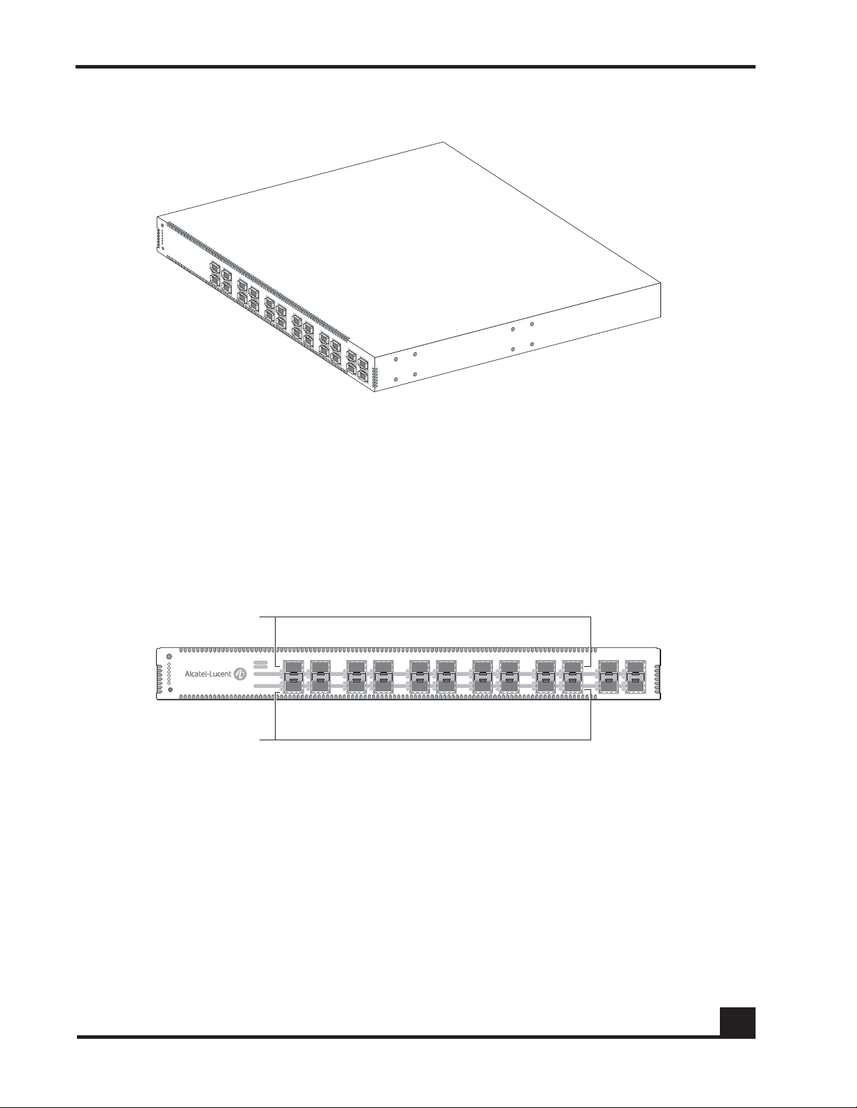
Figure 1 Secure LAN Controller (OAG2400 shown)
Front-Panel Interfaces
The OAG2400 SafeGuard Controller has 24 front-panel ports (Figure 2); the OAG1000
SafeGuard Controller has 10 front-panel ports (Figure 3). Each port has two associated
LEDs. One LED indicates link status. You can program the other LED to indicate activity,
duplex mode, or speed for the port.
Figure 2 OAG2400 Front Panel
OmniAccess SafeGuard Controller Installation Guide
15
Page 16
Chapter 1: Overview of the SafeGuard Controller
CST_023
Core
Edge
214
3
658710
9
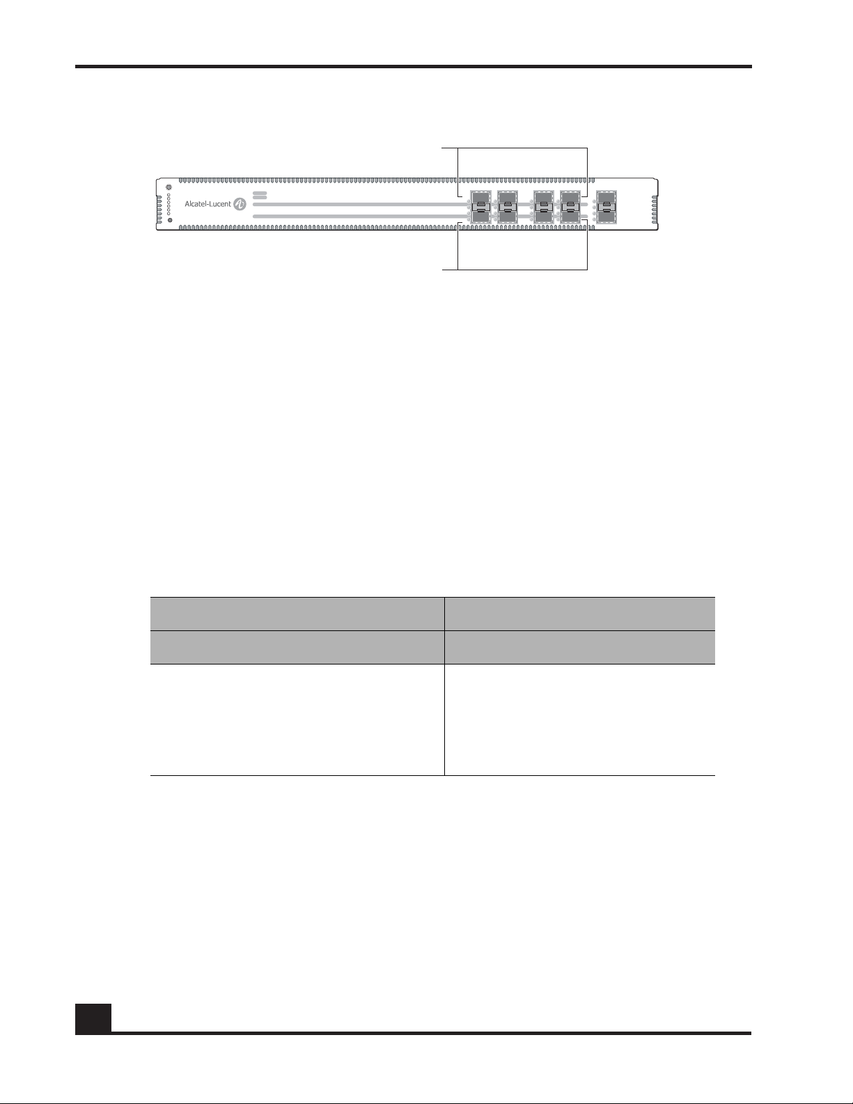
Figure 3 OAG1000 Front Panel
Each SafeGuard Controller model has secured port pairs that act as bridged ports. These
ports can be configured to be synchronized, so that when one port in the pair comes up,
its paired port comes up. Similarly, when one port in the pair goes down, its paired port
goes down. Within each pair, the top port (odd-numbered) is used to connect the
SafeGuard Controller to the upstream core or distribution switch. The bottom port (evennumbered port) is used to connect the SafeGuard Controller to the downstream access
(wire-closet) switches. The OAG2400 has 10 core ports and 10 edge ports. The OAG1000
has four network ports and four host ports.
Both SafeGuard Controller models have extensibility ports that include a reserved highavailability port for connecting a peer SafeGuard Controller of the same type and either
one (OAG1000) or two (OAG2400) ports for monitoring. In addition, the OAG2400 has a
port that is reserved for future use. Tab l e 3 lists the functions of the extensibility ports.
Table 3 Extensibility Ports
OAG2400 OAG1000
Port Label Purpose Port Label Purpose
21 EXT1 Monitoring 9 EXT1 Monitoring
22 EXT2 Monitoring 10 EXT2 High availability
23 EXT3 Future development
24 EXT4 High availability
Each front-panel port can be customized by inserting the proper SFP module. The SFP
modules supported are single-mode and multi-mode fiber and single-speed and triplespeed copper modules. You can mix and match different types in the same unit. For more
information about the SFP modules, see Small Form-Factor Pluggable (SFP) Modules on
page 18.
16
To comply with the IEEE 802.3ab standard, by default, the front-panel 10/100/1000 ports
of the SafeGuard Controller are capable of auto-negotiation for speed and duplex
settings. For example, with auto-negotiation enabled by default, the port detects the
interface settings and auto-configures support for the full-duplex or fastest line speed,
OmniAccess SafeGuard Controller Installation Guide
Page 17

depending on the speed and duplex settings of the attached interfaces. If a specific speed
CST_002
Ethernet
RJ-45
AC input AC inputRS-232
(DB-9)
Compact
flash
Ground
screw
Ground
screw
CST_022
Ethernet
RJ-45
DC input AC inputRS-232
(DB-9)
Compact
flash
Ground
screw
Ground
screw
for the interface is important, we recommend that you specify the speed of the interface
using the command line interface (CLI). Auto-negotiation is available on the 10/100/
1000 ports. Half-duplex operation is supported only at the 10/100 speed.
SafeGuard Controller Rear Panel
The rear panel of the SafeGuard Controller includes management ports, a compact flash
slot, and power connectors. The SafeGuard Controller is available with dual AC power
supplies (Figure 4) or one AC power supply and one DC power supply (Figure 5).
Figure 4 SafeGuard Controller Rear Panel—Dual AC Power Supplies
Chapter 1: Overview of the SafeGuard Controller
Figure 5 SafeGuard Controller Rear Panel—AC and DC Power Supplies
The SafeGuard Controller management ports are:
■ One RJ-45 10/100 BASE-T Ethernet port for out-of-band IP-based management
■ One RS-232 management port (male DB-9, DTE) to access the CLI
The compact flash slot provides a way to store configuration files.
The SafeGuard Controller provides two power input connectors, either two AC
connectors or an AC and a DC connector. Although a single power connection is
adequate to operate the SafeGuard Controller, connecting both power supplies provides
backup power that can prevent unscheduled downtime.
OmniAccess SafeGuard Controller Installation Guide
17
Page 18

Chapter 1: Overview of the SafeGuard Controller
Power Supplies
The SafeGuard Controller is available in either of the following power configurations:
■ Dual AC power supplies
■ One AC power supply and one DC supply input
The system is fully functional with one power cord connected; however, to ensure that
your system is operational at all times, install both power cords and make sure that both
power cords are connected to different circuits. When one power source fails, the
secondary power source becomes the new power source for the SafeGuard Controller.
For uninterrupted operation, it is preferred that one circuit have battery backup. In this
way, even if one circuit malfunctions, the system still remains operational with the help of
the power supplied by the secondary power source.
The AC power supply for the SafeGuard Controller has a voltage range from 100 to 240
VAC with a maximum current of 2.2 A at 100 VAC. The DC power input has a maximum
current of 3.1 A at 48 VDC.
With both AC power supplies connected, the maximum power that is drawn is no more
than 2.2 A at 100 VAC from an AC supply or 3.1 A at 48 VDC from a DC supply.
CAUTION: The SafeGuard Controller has redundant power supplies. You
must disconnect both power cords to completely remove power from the
unit.
Small Form-Factor Pluggable (SFP) Modules
The SafeGuard Controller supports both fiber and copper SFP modules. You can mix and
match different types in the same unit.
The SafeGuard Controller uses any of the following types of SFP modules:
■ 1000BASE-LX single-mode fiber
■ 1000BASE-SX multi-mode fiber
■ 10/100/1000BASE-T
NOTE: SFP modules can operate at 10, 100, or 1000 Mbps in full-duplex mode
or 10 or 100 Mbps in half-duplex mode.
18
OmniAccess SafeGuard Controller Installation Guide
Page 19

NOTE: Not all SFP modules support 10/100 operation. To ensure guaranteed
CST_016
Mode button
operation of the system, obtain all SFP modules from Alcatel-Lucent.
System and Port LEDs
The front panel of the SafeGuard Controller provides LEDS to indicate operating status of
the SafeGuard Controller system and ports (Figure 6).
Figure 6 Front-Panel LEDs (OAG2400 Shown)
Chapter 1: Overview of the SafeGuard Controller
At the left side of the front panel are six LEDs and a push button labeled Mode. The top
three LEDs indicate power and alarm status for the SafeGuard Controller system; the
three lower LEDs are linked to the port LEDs and indicate the operating mode for one
port LED in each pair.
Each port has two associated LEDs. The upper LED is bicolor amber and green, and the
lower LED is green. The lower LED always indicates link status for the port. The upper
LED indicates one of three possible conditions, depending on which mode has been
selected using the Mode button at the upper left corner of the front panel. Pushing the
Mode button cycles through the modes and selects speed, duplex, or status as the
condition being indicated by the upper port LEDs.
Only one of the three port mode LEDs is on at any time. Pushing the Mode button cycles
through these three LEDs and changes the operating mode of the upper LEDs for the
ports. For example, when the Speed LED is on, the upper port LEDs indicate operating
speed for the ports. If you push the Mode button until the Status LED is on, the upper
port LEDs indicate the port protection mode.
OmniAccess SafeGuard Controller Installation Guide
19
Page 20

Chapter 1: Overview of the SafeGuard Controller
Ta b le 4 describes the meanings of the system and port mode LEDs; Ta bl e 5 describes the
meanings of the port LEDs.
Table 4 System and Port Mode LEDs
Label Color Meaning
Power1 Green Lights when power supply 1 is on.
Power2 Green Lights when power supply 2 is on.
Alarm Amber Lights when an alarm condition exists.
Speed Green Lights when the upper port LED indicates operating speed:
10, 100, or 1000 Mbps.
Duplex Green Lights when the upper port LED indicates port duplex
mode: full-duplex or half-duplex.
Status Green Lights when the upper port LED indicates port protection
mode: monitor, pass-through, or protect.
Table 5 Port LEDs
LED Position Mode or Type Function Color and Meaning
Upper Speed Port operating speed Off: 10 Mbps
Green: 100 Mbps
Amber: 1000 Mbps
Duplex Port duplex mode Off: Link down
Amber: Half-duplex
Green: Full-duplex
Blinking: Collision
Status Port protection mode Off: Pass-through
Amber: Monitor
Green: Protect
Lower Link Port link status Off: Link down
Green: Link up
Blinking: Tx or Rx activity
20
OmniAccess SafeGuard Controller Installation Guide
Page 21

chapter
Site Preparation and
2
Installation
In this chapter:
■ Preparing for Installation
■ Checking the Package Contents
■ Installing the SafeGuard Controller on a Table or Shelf
■ Installing the SafeGuard Controller in a Rack
■ Connecting Power to the SafeGuard Controller
■ Installing Small Form-Factor Pluggable (SFP) Modules
■ Connecting Cables
■ Initial Configuration
■ Troubleshooting
Page 22

Chapter 2: Site Preparation and Installation
Preparing for Installation
The Alcatel-Lucent SafeGuard Controller can be installed on a shelf or tabletop or in a
standard 19-inch equipment rack. When you plan the installation of the SafeGuard
Controller, consider space, weight, power, rack, and environmental requirements. For a
rack-mounted SafeGuard Controller, make sure that the rack meets the requirements
listed in Rack Requirements on page 23.
NOTE: Before you install the SafeGuard Controller, be sure to review the
safety guidelines in Appendix B, Safety and Regulatory Compliance.
Space and Weight Requirements
Allow adequate space for unpacking and maneuvering the SafeGuard Controller during
installation. You will need space to set aside the packing materials and accessory boxes
during the installation process.
For a table or shelf installation, allow an area at least 18 inches wide and 19 inches deep.
Allow for these dimensions plus any additional clearances for proper front-to-back
cooling of the system. No side, top, and bottom clearances are required because the
SafeGuard Controller is cooled from the front to the back. This cooling arrangement
allows several systems to be stacked one on top of the other for either table or rackmounted configurations.
The SafeGuard Controller weighs approximately 20.0 pounds (9.1 kg). It can be easily
installed and mounted by two people. If you are installing more than one SafeGuard
Controller on a table, make sure that the table can support the combined weight of all the
controllers.
Power Requirements
You can provide power for the SafeGuard Controller in either of the following ways:
■ For a SafeGuard Controller with two AC power supplies, use two 110 VAC power
input sources.
■ For a SafeGuard Controller with one AC power supply and one DC supply input,
use one 110 VAC power source and one 48 VDC power source.
The AC power supply for the SafeGuard Controller has a voltage range from 100 to 240
VAC with a maximum current of 2.2 A at 100 VAC. The DC power input has a maximum
current of 3.1 A at 48 VDC.
22
For either power configuration, a single power source can operate the SafeGuard
Controller, and the second source provides backup.
OmniAccess SafeGuard Controller Installation Guide
Page 23

We recommend that you provide a 10-A fuse on your external DC connection to
safeguard against connecting the power source with the incorrect polarity.
The SafeGuard Controller does not have a power switch. To be able to disconnect the
power cords when needed, make sure that the power connections are easily accessible.
Make sure that the AC power input source connection is within 8 feet of the SafeGuard
Controller installation location.
Rack Requirements
The SafeGuard Controller is designed to fit into an industry-standard, 19-inch four-post
or two-post (telco-style) equipment rack. The rack should meet the requirements listed in
Ta b le 6 .
Table 6 Rack Requirements
Rack type EIA standard 19-inch, four-post or two-post
Chapter 2: Site Preparation and Installation
Vertical rack space needed 1 RU—1.7 inches (4.4 cm) for each installed SafeGuard
Horizontal depth needed 18.6 inches (47.2 cm)
Stability Bolted to the floor, ceiling, wall, or other secured racks
Grounding Grounded
Strength Support for 20.0 pounds (9.1 kg) for each installed Safe-
Environmental Requirements
To ensure optimal system operation, make sure that the installation site meets the
environmental requirements listed in Ta bl e 7 .
Table 7 Environmental Requirements
Operating temperature 0° C to +40° C
Storage temperature 0° C to +40° C
Operating relative humidity 5 to 90% (non-condensing)
Controller
Guard Controller
Storage relative humidity 5 to 95% (non-condensing)
OmniAccess SafeGuard Controller Installation Guide
23
Page 24

Chapter 2: Site Preparation and Installation
Grounding Options
The recommended grounding method for the SafeGuard Controller is to use the
grounding stud immediately to the left of each power input connector. Connect this stud
to earth ground (for example, a grounded rack).
Recommended Cables
Fiber-optic SFP modules require fiber-optic cables with LC connectors. Depending on the
type of SFP module, use either of the following cables:
■ 1000BASE-LX SFP module: single-mode, 1310 nm, 10-km range
■ 1000BASE-SX SFP module: multi-mode, 850 nm, 550-m range
Copper SFP modules require a Category 5 or better cable with RJ-45 connectors.
Depending on the connected device, you can use either crossover or straight-through
cables. Ta bl e 8 lists the recommended cable types.
Table 8 Using Crossover or Straight-through Cables
SafeGuard Controller to . . . Crossover Cable Straight-Through Cable
Downstream switch or router Yes No
Upstream switch Yes Yes
To connect the Ethernet management port on the rear panel, use a Category 5 or better
Ethernet cable with RJ-45 connectors. For connector specifications, see Appendix A,
Technical Specifications.
To connect the serial console port on the rear panel, use an RS-232 cable with a DB-9
connector. For connector specifications, see Appendix A, Technical Specifications.
Checking the Package Contents
Make sure that you received the following components:
■ Secure LAN Controller
■ Two pow e r c ord s :
24
— For an ACAC model, two AC power cords (18 AWG, 125 V, 10 A)
— For an ACDC model, one AC power cord (18 AWG, 125 V, 10 A) and one
three-position 2.8-mm terminal plug for 48-VDC connection
■ Documentation on a CD-ROM
OmniAccess SafeGuard Controller Installation Guide
Page 25

Chapter 2: Site Preparation and Installation
■ RS-232 (DB-9) configuration cable
■ Mounting accessories, including:
— Four rubber feet for installing the SafeGuard Controller on a table
— Two brackets for installing the SafeGuard Controller in a rack
— Six Phillips screws for attaching the brackets to the SafeGuard Controller
■ Disposable ESD wrist strap
■ SFP modules and cables as determined when the SafeGuard Controller was
ordered
NOTE: You must provide rack-mounting screws appropriate to your
equipment rack and the cable for use with the DC terminal plug.
Installing the SafeGuard Controller on a Table or Shelf
To install the SafeGuard Controller on a table or shelf, follow these steps:
1 Lift the controller carefully from the packing material and place it upside down
on a flat surface.
2 Locate the recessed areas on the bottom of the controller, and attach the four
rubber feet from the mounting kit.
3 Place the controller on a table or shelf close to an AC power source.
For the ACDC model, an additional 48-VDC power source should be available.
For instructions on connecting the power cords, see Connecting Power to the SafeGuard
Controller on page 29.
Installing the SafeGuard Controller in a Rack
You can attach the rack-mounting brackets to the SafeGuard Controller in either of the
following positions:
■ At the front of the controller to install it in a four-post rack
■ At the middle of the controller to install it in a two-post (telco-type) rack
OmniAccess SafeGuard Controller Installation Guide
25
Page 26
Chapter 2: Site Preparation and Installation
CST_005
Four-Post Rack
To install the SafeGuard Controller in a four-post rack, follow these steps:
1 Lift the controller carefully from the packing material, and set it on a level work
surface.
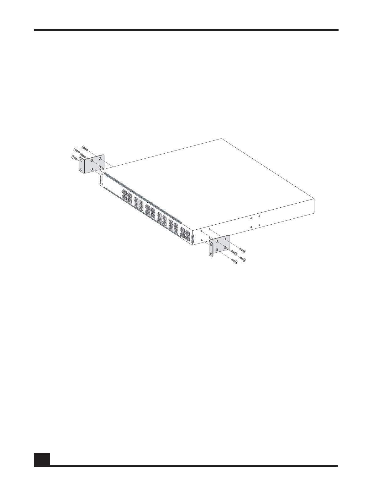
2 Using the screws from the mounting accessory kit, attach the rack-mounting
brackets, as shown in Figure 7.
Figure 7 Attaching the Rack-Mounting Brackets at the Front
26
3 Slide the controller into the rack, and align the mounting holes.
4 Using screws appropriate to the equipment rack, attach the brackets to the rack, as
shown in Figure 8.
OmniAccess SafeGuard Controller Installation Guide
Page 27

CST_006
Chapter 2: Site Preparation and Installation
Figure 8 Installing the SafeGuard Controller in a Four-Post Rack
For instructions on connecting the power cords, see Connecting Power to the SafeGuard
Controller on page 29.
OmniAccess SafeGuard Controller Installation Guide
27
Page 28

Chapter 2: Site Preparation and Installation
CST_007
Two-Post Rack
To install the SafeGuard Controller in a two-post rack, follow these steps:
1 Lift the controller carefully from the packing material, and set it on a flat work
surface.
2 Using the screws from the mounting accessory kit, attach one rack-mounting
bracket to the middle of each side, as shown in Figure 9.
Figure 9 Attaching the Rack-Mounting Brackets at the Middle
28
3 Slide the controller into the rack, and align the mounting holes.
4 Using screws appropriate to the equipment rack, attach the brackets to the rack, as
shown in Figure 9.
For instructions on connecting the power cords, see Connecting Power to the SafeGuard
Controller on page 29.
OmniAccess SafeGuard Controller Installation Guide
Page 29

CST_008
Chapter 2: Site Preparation and Installation
Connecting Power to the SafeGuard Controller
This section describes how to connect power to the AC and DC power input connections
on the rear panel of the SafeGuard Controller. An AC power cord is provided for each AC
power input on the SafeGuard Controller. For the DC power input, you must attach an
appropriate three-wire cable to the provided DC connector.
AC Power
To connect the SafeGuard Controller to an AC power source, follow these steps:
1 Connect an AC power cord to an AC power connector on the SafeGuard
Controller rear panel, as shown in Figure 10.
Figure 10 Connecting AC Power Cords (Model ACAC Shown)
2 Connect the other end of the power cord to a grounded AC outlet.
3 For an ACAC model in a redundant power configuration, repeat these steps to
connect the second AC power supply.
For more information about power requirements for the SafeGuard Controller, see
Appendix A, Technical Specifications.
OmniAccess SafeGuard Controller Installation Guide
29
Page 30

Chapter 2: Site Preparation and Installation
CST_024
Retaining
screws
DC Power
The OAG2400-ACDC and OAG1000-ACDC SafeGuard Controllers provide a DC power
input connector that allows you to use a 48-VDC power source as backup for the system.
You must provide the appropriate cable for use with the connector.
NOTE: We recommend that you provide a 10-A fuse on your external DC
connection to safeguard against connecting the power source with the
incorrect polarity.
To attach the connector to a three-wire cable, follow these steps:
1 Strip 1/8 inch from the end of each wire.
2 Loosen the retaining screws along the side of the connector (see Figure 11).
Figure 11 Attaching the DC Connector to a Cable
3 Insert each wire firmly into the connector, and tighten the retaining screw to
secure the wire. Make sure that no wire is exposed beyond the connector housing.
With the retaining screws at the left, the order of wires from top to bottom is red,
black, and green.
30
OmniAccess SafeGuard Controller Installation Guide
Page 31

CST_025
Connector
retaining screws
Chapter 2: Site Preparation and Installation
To connect the SafeGuard Controller to a DC power source, follow these steps:
1 Turn off the DC power at the source.
2 Connect the DC connector on the cable to the SafeGuard Controller, as shown in
Figure 12.
Figure 12 Connecting the DC Power Cord
3 Align and tighten the captive retaining screws at the top and bottom of the
connector.
4 Connect the other end of the DC power cable to the DC power source.
5 Turn on the DC power at the source.
Installing Small Form-Factor Pluggable (SFP) Modules
To communicate reliably over fiber-optic cables, make sure that the wavelength of each
port matches the wavelength specifications on the other end of the cable. Fiber SFP
modules inserted into odd-numbered ports should be oriented so that the send (Tx) and
receive (Rx) marks are facing up, and modules inserted into even-numbered ports should
be oriented so that the Tx and Rx marks are facing down.
To avoid damaging the cables, connectors, and optical interfaces, always disconnect
cables from SFP modules before inserting or removing the modules. To prevent
unnecessary wear and tear, insert or remove SFPs only when necessary.
OmniAccess SafeGuard Controller Installation Guide
31
Page 32

Chapter 2: Site Preparation and Installation
CST_013
The insertion procedure for copper and fiber SFP modules is the same. To insert an SFP
module, follow these steps:
1 Put on the ESD-preventive wrist strap, and attach the leash to a grounded bare
metal surface on the SafeGuard Controller or equipment rack.
2 Identify the Tx and Rx marks on the top of the SFP module.
3 Align the module with the SFP module slot, and push it firmly into place until it
clicks into place and is completely seated (see Figure 13).
Figure 13 Inserting an SFP Module
4 Check that the SFP module is completely seated by gently pulling on it to see if it
comes out of the slot.
Connecting Cables
Connect the front-panel ports using cables appropriate to the installed SFP modules:
■ Single-mode or multi-mode fiber cable with LC connectors
■ Category 5 or better copper cable with RJ-45 connectors
■ For Gigabit Ethernet connections, Category 5e copper cable with RJ-45 connectors
Connect the Ethernet management port using Category 5 or better cable with RJ-45
connectors, as shown in Figure 14.
32
OmniAccess SafeGuard Controller Installation Guide
Page 33

CST_012
CST_015
Chapter 2: Site Preparation and Installation
Figure 14 Connecting the Ethernet Management Port
Connect the serial console port using an RS-232 cable with a DB-9 connector, as shown in
Figure 15. The default settings for this port are 9600 baud, 8 data bits, 1 stop bit, and no
parity or flow control (9600 8-N-1 none). The default settings may be changed either in
the boot monitor or during system operation.
Figure 15 Connecting the Serial Console Port
OmniAccess SafeGuard Controller Installation Guide
33
Page 34

Chapter 2: Site Preparation and Installation
Initial Configuration
To assign IP addresses and perform other initial configuration tasks, refer to the
OmniAccess SafeGuard OS Administration Guide.
Troubleshooting
Ta b le 9 provides suggestions for troubleshooting basic hardware issues that might arise
when you install the SafeGuard Controller.
The software documentation provides detailed troubleshooting instructions for operating
and configuration issues. If after reviewing the software documentation your trouble is
not resolved, consult the Alcatel-Lucent Technical Assistance Center.
Table 9 Troubleshooting Basic Hardware issues
Cable and Connectivity Issues
For this problem . . . Take these actions. . .
No link exists when the optical
cable is connected.
The SafeGuard Controller does not
have connectivity when the
copper cable is connected.
Port Issues
For this problem . . . Take these actions. . .
Ports are malfunctioning.
■ Verify that you have used the correct cable for the port
type.
■ Clean the connectors, and reconnect the cable.
■ Try a new cable.
■ If you are using the factory default configuration, make
sure that the port has been enabled through the CLI.
■ Make sure that you are using the correct choice of
crossover or straight-through cable.
■ If the cable type is correct, check the connector
pinouts to verify that the cable is wired correctly.
■ Remove and reinsert the affected SFP module.
■ For optical ports, clean the cable connectors, and
reconnect the cable.
■ Try a new cable.
Management Console Issues
For this problem . . . Take these actions. . .
The SafeGuard Controller
management console displays
unreadable characters.
34
Check for an incorrect baud rate and make sure that the
baud rate for the terminal emulation software is set to 9600.
OmniAccess SafeGuard Controller Installation Guide
Page 35

appendix
A
Technical Specifications
In this appendix:
■ Physical Specifications
■ Environmental Specifications
■ Connector Pinouts
■ SFP Module Types and Cables
Page 36

Appendix A: Technical Specifications
Physical Specifications
Ta b le 1 0 lists the physical specifications of the SafeGuard Controller.
Table 10 Physical Specifications
Dimensions Width: 17.3 inches (43.9 cm)
Depth: 18.6 inches 47.2 cm
Height: 1.7 inches (4.4 cm)
Approximate Weight 20.0 pounds (9.1 kg)
Environmental Specifications
Ta b le 11 lists environmental specifications for the SafeGuard Controller.
Table 11 Environmental Specifications
Operating temperature 0° C to +40° C
Storage temperature 0° C to +40° C
Operating Relative Humidity 5 to 90% (non-condensing)
Storage Relative Humidity 5 to 95% (non-condensing)
NOTE: The SafeGuard Controller is cooled from the front to the back. Because
of this cooling arrangement, keep the air vents clean so that the SafeGuard
Controller is cooled properly.
36
OmniAccess SafeGuard Controller Installation Guide
Page 37

Connector Pinouts
This section provides pinout information for the following connectors on the SafeGuard
Controller:
■ RJ-45 connectors on copper SFP modules used in the front-panel ports (Tab l e 1 2 )
■ RJ-45 connector on the rear-panel Ethernet management port (Tab l e 1 3 )
■ DB-9 connector on the rear-panel serial console port (Tab le 1 4)
■ DC input power connector on the rear panel of ACDC models (Tab l e 1 5 )
Table 12 Front-Panel Copper Port Pinouts
Pin 10/100BASE-T 1000BASE-T
1RXp TPp_A
2RXn TPn_A
Appendix A: Technical Specifications
3TXp TPp_B
4NC TPp_C
5NC TPn_C
6TXn TPn_B
7NC TPp_D
8NC TPn_D
Table 13 Ethernet Management Port Pinouts
Pin 10/100BASE-T
1TXp
2TXn
3RXp
4NC
5NC
6RXn
7NC
8NC
OmniAccess SafeGuard Controller Installation Guide
37
Page 38

Appendix A: Technical Specifications
CST_024
Retaining
screws
Table 14 RS-232 Serial Management Port Pinouts for Male DB-9
Pin RS-232 Function Source
1 DCD (RSLD) DTE
2RXDDTE
3TXDDTE
4DTRDTE
5GND6DSRDTE
7RTSDTE
8CTSDTE
9RIDTE
Table 15 DC Input Connector Pinouts
Pin Description
1 Earth ground
2GND
3+48 VDC
NOTE: Pin 1 is at the bottom in Figure 16.
Figure 16 DC Input Connector
38
OmniAccess SafeGuard Controller Installation Guide
Page 39

SFP Module Types and Cables
The SafeGuard Controller uses the types of SFP modules and cables listed in Ta b l e 1 6 .
Table 16 SFP Modules and Cables
SFP Module Type Required Cable
1000BASE-LX Single-mode fiber, 1310 nm, 1-km range
1000BASE-SX Multi-mode fiber, 850 nm, 550-m range
10/100/1000BASE-T Category 5 or better copper for 10/100BASE-T
Category 5e or better for 1000BASE-T
Appendix A: Technical Specifications
OmniAccess SafeGuard Controller Installation Guide
39
Page 40

Appendix A: Technical Specifications
40
OmniAccess SafeGuard Controller Installation Guide
Page 41

appendix
Safety and Regulatory
B
Compliance
In this appendix:
■ Safety Guidelines
■ Agency Safety Approvals
■ Regulatory Compliance and Notices
Page 42

Appendix B: Safety and Regulatory Compliance
Safety Guidelines
Review the recommendations in this section before you install the Alcatel-Lucent
SafeGuard Controller.
General Safety Recommendations
The following recommendations will help ensure your safety and prevent damage to the
equipment:
■ Always be careful when lifting and moving heavy or awkward objects. The
SafeGuard Controller weighs 20 pounds and may require two people to
maneuver it when you install it in a rack.
■ Always begin loading a rack from the bottom to the top, especially when you
are installing only one SafeGuard Controller.
■ Populate the bottom of the rack with the heaviest component.
■ While installing the SafeGuard Controller, take the necessary precautions to avoid
bodily injury. Make sure that the SafeGuard Controller can be held in a stable
position when lifting, mounting, or servicing it.
■ Do not wear jewelry when you work on electrical or mechanical equipment.
■ If you plan to stack several SafeGuard Controllers, take care that the SafeGuard
Controllers are properly installed in a rack or on a table.
WARNING: The SafeGuard Controller is a Class 1 Laser device.
Safety with Electricity
Follow these recommendations when you are working around electrical equipment:
■ To be able to disconnect the power cords when needed, make sure that the sockets
are easily accessible.
■ Disconnect all power cables before you install or remove the SafeGuard
Controller.
42
■ Never assume that the source power for the SafeGuard Controller is off; always
check.
■ When you connect or disconnect power, always connect ground first and
disconnect ground last.
OmniAccess SafeGuard Controller Installation Guide
Page 43

Appendix B: Safety and Regulatory Compliance
■ Lightning can cause electromagnetic surges and can damage your equipment.
Even if lightning strikes a nearby power line that feeds your site, a surge in
voltage can occur and cause electromagnetic energy. As a precaution during
lightning storms, do not connect or disconnect cables.
■ Always make sure that your cables do not exceed recommended lengths or are
not exposed to the outside environment. In either case, the likelihood of lightningrelated damage increases.
■ Make sure that the SafeGuard Controller is grounded securely. A voltage surge
that occurs in the power lines may affect the grounding system, especially if the
grounding system has a very low resistance. If an electromagnetic surge occurs,
consult experienced electrical surge suppression personnel. They will be able to
help your site recover from the effects of the surge.
Electromagnetic Interference Prevention
Electromagnetic interference (EMI) is any electromagnetic disturbance that interrupts,
obstructs, or otherwise degrades the effective performance of electronics equipment.
Interference of this nature refers to the impact it has on the equipment, thereby affecting
performance of other equipment. Because of EMI, power surges can cause an electrical
hazard or damage signal drivers and receivers. As a precaution against EMI-related
damage, store all X-ray equipment, hand-held transceivers, and microwave, radio, or
television transmitters in a facility that is different from the one in which the SafeGuard
Controller is installed. To resolve problems with continual high levels of EMI, consult
experienced EMI personnel.
Radio Frequency Interference Prevention
Radio frequency interference (RFI) is high-frequency electromagnetic radiation that
upsets the electromagnetic environment. RFI is also known as electromagnetic
interference (EMI), but EMI actually encompasses a wider range of frequencies.
If your cables are improperly installed, they can emit RFI. At all times, make sure that
your system cables are properly and securely installed, and do not exceed the
recommended lengths. If your cables exceed the recommended lengths, use high-quality
cables with proper grounding. Using shielded cables helps reduce RFI radiation. If
electromagnetic interference persists at your site, consult experienced RFI and EMI
personnel.
Electrostatic Discharge Precautions
Components used in the SafeGuard Controller and SFP modules are sensitive to damage
from static electricity. A damaging electrical charge can be generated by handling plastic
or foam packaging material. The effect of electrostatic discharge (ESD) damage can be
OmniAccess SafeGuard Controller Installation Guide
43
Page 44

Appendix B: Safety and Regulatory Compliance
immediate failure, or it can show up as a latent failure affecting the reliability of the
equipment.
To minimize the likelihood of ESD damage to the SafeGuard Controller, follow these
guidelines when you are handling the SafeGuard Controller or SFP modules:
■ Always use an antistatic wrist strap or other antistatic device.
To use the disposable ESD wrist strap that is provided, put the strap on your
wrist, ensuring that it makes good contact with the skin. Peel the protective liner
from the copper foil at the other end of the wrist strap and connect the foil to any
accessible electrical ground that is nearby and exposed.
■ Leave the SafeGuard Controller and SFP modules in antistatic packaging until
you are ready to install them.
■ Always place the SafeGuard Controller on an antistatic mat when it has been
removed from the rack.
Agency Safety Approvals
The SafeGuard Controller has been tested and has obtained the following agency
approvals:
■ CAN/CSA-22.2 No. 60950-1
■ EN 60950-1
■ IEC 60950-1
■ UL 60950-1
Regulatory Compliance and Notices
The SafeGuard Controller meets the following EMC regulatory compliance requirements:
■ EN 55022 (Emissions), Class A
■ EN 55024 (Immunity)
■ Industry Canada Class A
■ FCC Part 15 Class A
44
■ VCCI Class A (Japan)
OmniAccess SafeGuard Controller Installation Guide
Page 45

FCC Part 15 Class A
This equipment has been tested and found to comply with the limits for a Class A digital
device, pursuant to Part 15 of the FCC Rules. These limits are designed to provide
reasonable protection against harmful interference in a commercial environment. This
equipment generates, uses, and can radiate radio frequency energy. If the equipment is
not installed and used in accordance with the instruction manual, it may cause harmful
interference to radio communications. Operation of this equipment in a residential area is
likely to cause harmful interference, in which case users are required to correct the
interference at their expense.
Where specified throughout this guide, properly shielded and grounded cables and
connectors must be used to meet FCC emission limits. Alcatel-Lucent is not responsible
for any radio or television interference caused by the use of incorrect customer cabling.
Unauthorized product cabling changes or other modifications could void the authority of
the user to operate the equipment. This device complies with Part 15 of the FCC Rules.
Operation is subject to the following conditions:
■ This device may not cause harmful interference.
Appendix B: Safety and Regulatory Compliance
■ This device must accept any interference received, including interference that
may cause undesired operation.
Japan VCCI Class A
This is a Class A product based on the standard of the Voluntary Control Council for
Interference (VCCI) by Information Technology Equipment. If this equipment is used in a
domestic environment, radio disturbance may occur that may require you to take
corrective action.
OmniAccess SafeGuard Controller Installation Guide
45
Page 46

Appendix B: Safety and Regulatory Compliance
46
OmniAccess SafeGuard Controller Installation Guide
Page 47

appendix
C
Customer Assistance and Product Support
Page 48

Appendix C: Customer Assistance and Product Support
Alcatel-Lucent technical support is committed to resolving our customer's technical
issues in a timely manner. Customers with inquiries should contact us at:
■ North America Service and Support: 1-800-995-2696
■ Latin America Service and Support: 1-877-919-9526
■ European Service and Support: +33-38-855-6929
■ Asia Pacific Service and Support: +65-6586-1555
■ Other International: 1-818-878-4507
■ Email: support@ind.alcatel.com
■ Internet: Customers with Alcatel-Lucent service agreements may open cases 24
hours a day via Alcatel-Lucent's support web page at:
— Support URL: http://www1.alcatel-lucent.com/enterprise/en/support/
index.html
— Documentation URL: http://www1.alcatel-lucent.com/enterprise/en/
resource_library/user_manuals.html
48
OmniAccess SafeGuard Controller Installation Guide
Page 49

Index
Numerics
10/100 ports . . . 17, 32, 37
10/100/1000 ports . . . 16
48-VDC power source . . . 22, 30
802.3ab standard . . . 16
A
AC power supplies . . . 17, 18, 22
access point . . . 14
Active Directory . . . 14
addresses, assigning . . . 34
agency safety approvals . . . 44
antistatic precautions . . . 25, 44
approvals, safety . . . 44
Assistance Center (TAC) . . . 34
auditing, user-based . . . 14
authentication infrastructure . . . 14
auto-negotiation . . . 16
B
backup power . . . 17
battery backup . . . 18
bridged ports . . . 16
button, Mode . . . 19
connector pinouts . . . 37–38
connectors, LC . . . 24
console, management . . . 34
contents of package . . . 24
cooling space . . . 22
cords, power . . . 18, 24
core ports . . . 16
current, maximum . . . 18, 22
D
DC power supplies . . . 18, 22
documentation . . . 24, 34
dual AC power supplies . . . 17, 22
duplex mode . . . 17, 20
E
earth ground . . . 24, 43
edge ports . . . 16
electromagnetic interference (EMI) . . . 43
electromagnetic surge . . . 43
environmental requirements . . . 23, 36
Ethernet
cable . . . 24
ports . . . 16, 17, 32, 37
extensibility ports . . . 16
C
cables . . . 24, 32
compact flash slot . . . 17
compliance initiatives . . . 14
configuration, initial . . . 34
connecting power . . . 29–31
connectivity, lack of . . . 34
OmniAccess SafeGuard Controller Installation Guide
F
front panel
LEDs . . . 19
ports . . . 15–17, 32
functionality of SLC . . . 14
fuse . . . 23, 30
49
Page 50

Index
G
grounding . . . 24, 43
H
half-duplex operation . . . 17, 20
hardware description
cables . . . 24
environmental requirements . . . 23, 36
front-panel ports . . . 15–17
grounding . . . 24
LEDs . . . 19–20
overview . . . 14
physical specifications . . . 36
rack requirements . . . 23
rear panel . . . 17
help center . . . 34
host ports . . . 16
humidity . . . 23, 36
I
IEEE 802.3ab standard . . . 16
initial configuration . . . 34
installation
rack . . . 25–28, 42
space required . . . 22
table or shelf . . . 25
interface speed . . . 17
interference
electromagnetic (EMI) . . . 43
radio frequency (RFI) . . . 43
IP addresses, assigning . . . 34
issues, troubleshooting . . . 34
L
LC connectors . . . 24
LDAP (Lightweight Directory Access Protocol) . . .
14
LEDs . . . 19–20
Lightweight Directory Access Protocol (LDAP) . . .
14
link, missing . . . 34
M
malfunctioning ports . . . 34
malware . . . 14
management console . . . 34
management port . . . 17
management ports . . . 17, 32, 37, 38
maximum current . . . 18, 22
meltdown, preventing . . . 14
models of SLC . . . 14
N
network access point . . . 14
network meltdown, preventing . . . 14
network ports . . . 16
O
operating speed . . . 20
P
package contents . . . 24
paired ports . . . 16
physical specifications . . . 36
pinouts . . . 37–38
polarity . . . 23
ports
associated LEDs . . . 19–20
duplex mode . . . 17, 20
Ethernet . . . 16, 17, 32, 37
front panel . . . 15–17, 32
malfunctioning . . . 34
management . . . 17, 32, 37, 38
pairs, secured . . . 16
protection mode . . . 20
rear panel . . . 17
RS-232 . . . 17
serial console . . . 24, 33
power
connecting . . . 29–31
removing . . . 18
power cords . . . 18, 24
power input, location of . . . 23
power source, 48-VDC . . . 22, 30
power supplies . . . 17–18, 22, 25
power switch . . . 23
problems, troubleshooting . . . 34
50
OmniAccess SafeGuard Controller Installation Guide
Page 51

Index
protection mode . . . 20
R
rack installation . . . 25–28, 42
rack requirements . . . 23
radio frequency interference (RFI) . . . 43
RADIUS . . . 14
rear panel . . . 17
redundant power supplies . . . 18
RS-232 port . . . 17
S
safety approvals . . . 44
safety guidelines . . . 42–44
secured port pairs . . . 16
security posture . . . 14
serial console port . . . 24, 33
SFP (small form-factor pluggable) modules . . . 18,
31, 39
V
voltage range . . . 18, 22
W
weight . . . 22, 42
Windows Active Directory . . . 14
worms . . . 14
wrist strap . . . 25, 44
shelf installation . . . 25
space for installation . . . 22
speed
interface . . . 17
operating . . . 20
stacking . . . 22
static strap . . . 25, 44
surge, electromagnetic . . . 43
switch, power . . . 23
T
table installation . . . 25
Technical Assistance Center (TAC) . . . 34
temperatures . . . 23, 36
troubleshooting . . . 34
Trusted Computing Group . . . 14
U
unpacking . . . 24
user-based auditing . . . 14
OmniAccess SafeGuard Controller Installation Guide
51
Page 52

Index
52
OmniAccess SafeGuard Controller Installation Guide
 Loading...