

Page 1

OmniAccess
T
Reference
AOS-W System Reference
M
Page 2

OmniAccess Reference: AOS-W System Reference
Copyright
Copyright © 2005 Alcatel Internetworking, Inc. All rights reserved.
Specifications in this manual are subject to change without notice.
Originated in the USA.
Trademarks
AOS-W, OmniAccess 4304, OmniAccess 4308, OmniAccess Wireless LAN,
OmniAccess 6000, OmniAccess AP60, OmniAccess AP61, and OmniAccess
AP 70 are trademarks of Alcatel Internetworking, Inc. in the United States and
certain other countries.
Any other trademarks appearing in this manual are owned by their respective
companies.
Legal Notice
The use of Alcatel Internetworking, Inc. switching platforms and software, by
all individuals or corporations, to terminate Cisco or Nortel VPN client devices
constitutes complete acceptance of liability by that individual or corporation for
this action and indemnifies, in full, Alcatel Internetworking, Inc. from any and
all legal actions that might be taken against it with respect to infringement of
copyright on behalf of Cisco Systems or Nortel Networks.
ii Part 031652-00 May 2005
Page 3

Preface xix
An Overview of this Manual . . . . . . . . . . . . . . . xix
Related Documents
Text Conventions . . . . . . . . . . . . . . . . . . . . . xx
Contacting Alcatel
. . . . . . . . . . . . . . . . . . . . xx
. . . . . . . . . . . . . . . . . . . . . xxi
Part 1
Chapter 1
Overview
. . . . . . . . . . . . . . . . . . . . . . . 1
Overview . . . . . . . . . . . . . . . . . . . . . . . . 3
Key Features . . . . . . . . . . . . . . . . . . . . . . . . 3
Prevention of Layer-2 Bridging between
Wireless Users . . . . . . . . . . . . . . . . . . . . 3
Wired Port 802.1x Authentication
Enhanced Location Services . . . . . . . . . . . . . . 4
Web Management Interface Enhancements . . . . . 4
Enhanced Network Monitoring Interface
SNMPv3 . . . . . . . . . . . . . . . . . . . . . . . . . 4
Remote Thin AP . . . . . . . . . . . . . . . . . . . . . 4
Auto-Blacklist Firewall Extended Action
Enhanced AP-Switch Discovery and Alcatel
Discovery Protocol . . . . . . . . . . . . . . . . . 5
DHCP Configuration
Multicast Configuration. . . . . . . . . . . . . . . . . 8
. . . . . . . . . . . . . . . . . . . 6
. . . . . . . . . . . 3
. . . . . . . 4
. . . . . . . 5
Chapter 2 Management Options . . . . . . . . . . . . . . . 9
Command-Line Interface . . . . . . . . . . . . . . . . . . 9
Web Interface
General Screen Elements . . . . . . . . . . . . . . . 10
Page Elements . . . . . . . . . . . . . . . . . . . . . 11
. . . . . . . . . . . . . . . . . . . . . . . . 9
Chapter 3 Command Line Basics . . . . . . . . . . . . . 13
Connecting to the Switch . . . . . . . . . . . . . . . . 13
Local Serial Console. . . . . . . . . . . . . . . . . . 13
Local or Remote Telnet . . . . . . . . . . . . . . . . 14
Logging In
Access Modes . . . . . . . . . . . . . . . . . . . . . . . 15
Command Context . . . . . . . . . . . . . . . . . . . . 16
Saving Configuration Changes
Viewing the Configuration . . . . . . . . . . . . . . . . 17
Shortcuts . . . . . . . . . . . . . . . . . . . . . . . 18
Command Completion
Command Help . . . . . . . . . . . . . . . . . . . . 18
Command History . . . . . . . . . . . . . . . . . . . 19
Command Line Editing
Command Syntax . . . . . . . . . . . . . . . . . . . 20
. . . . . . . . . . . . . . . . . . . . . . . 15
. . . . . . . . . . . . . . 17
. . . . . . . . . . . . . . . . 18
. . . . . . . . . . . . . . . . 20
iii
Page 4

OmniAccess Reference: AOS-W System Reference
Part 2
Chapter 4
Design and Planning
. . . . . . . . . . . . 23
RF Design . . . . . . . . . . . . . . . . . . . . . . . 25
The Alcatel RF Plan Tool . . . . . . . . . . . . . . . . . . 25
Getting Started
System Requirements for Standalone RF Plan . . . 26
Installing RF Plan . . . . . . . . . . . . . . . . . . . . 26
Launching RF Plan
RF Plan Basics . . . . . . . . . . . . . . . . . . . . . . . 27
Page Summary . . . . . . . . . . . . . . . . . . . . . 27
Page Fields
Navigation . . . . . . . . . . . . . . . . . . . . . . . . 29
Applying and Saving . . . . . . . . . . . . . . . . . . 29
Next Step Button
Opening Screen. . . . . . . . . . . . . . . . . . . . . . . 30
Using RF Plan . . . . . . . . . . . . . . . . . . . . . . . . 31
Task Overview
Planning Requirements . . . . . . . . . . . . . . . . 32
Adding a New Building to the Plan . . . . . . . . . . . . 32
Planning Pages
Locating Devices . . . . . . . . . . . . . . . . . . . . . . 52
. . . . . . . . . . . . . . . . . . . . . . . 26
. . . . . . . . . . . . . . . . . . . 27
. . . . . . . . . . . . . . . . . . . . . . . 28
. . . . . . . . . . . . . . . . . . . . 29
. . . . . . . . . . . . . . . . . . . . . 31
. . . . . . . . . . . . . . . . . . . . . 41
Chapter 5 Security Options . . . . . . . . . . . . . . . . . 55
Default Open Ports . . . . . . . . . . . . . . . . . . . . . 56
AOS-W Security Options
User Roles . . . . . . . . . . . . . . . . . . . . . . . . 60
Role Design . . . . . . . . . . . . . . . . . . . . . . . 60
Role Configuration
Firewall and Traffic Policies . . . . . . . . . . . . . . . . 62
Introduction to Firewall and Traffic Policies . . . . . 62
Configuring Traffic Policies
Access Control Lists . . . . . . . . . . . . . . . . . . 70
Standard ACLs . . . . . . . . . . . . . . . . . . . . . 71
Extended ACLs
MAC ACLs . . . . . . . . . . . . . . . . . . . . . . . 72
Ethertype ACLs . . . . . . . . . . . . . . . . . . . . . 72
Authentication and Accounting Servers
RADIUS . . . . . . . . . . . . . . . . . . . . . . . . . 73
LDAP. . . . . . . . . . . . . . . . . . . . . . . . . . . 77
Internal Authentication Database
Accounting . . . . . . . . . . . . . . . . . . . . . . . 83
. . . . . . . . . . . . . . . . . . . . . 71
. . . . . . . . . . . . . . . . . 59
. . . . . . . . . . . . . . . . . . . 60
. . . . . . . . . . . . . . 63
. . . . . . . . . 72
. . . . . . . . . . . 82
iv Part 031652-00 May 2005
Page 5

Authentication Methods . . . . . . . . . . . . . . . . . 83
802.1x Authentication . . . . . . . . . . . . . . . . 84
VPN Authentication
Captive Portal Authentication . . . . . . . . . . . . 89
MAC Address Role Mapping . . . . . . . . . . . . . 91
Stateful 802.1x
SSID Role Mapping . . . . . . . . . . . . . . . . . . 94
Encryption Type Role Mapping . . . . . . . . . . . 95
Advanced Authentication
Configuring VPN Settings . . . . . . . . . . . . . . . . 97
IPSec . . . . . . . . . . . . . . . . . . . . . . . . . . 97
PPTP
VPN Dialer Configuration . . . . . . . . . . . . . . 101
VPN Server Emulation. . . . . . . . . . . . . . . . 104
Advanced Authentication
SecureID Token Caching . . . . . . . . . . . . . . 106
Firewall Settings . . . . . . . . . . . . . . . . . . . . . 107
Advanced Security Options
Service Aliases. . . . . . . . . . . . . . . . . . . . 109
Source/Destination Aliases . . . . . . . . . . . . . 110
Bandwidth Contracts
NAT Pools . . . . . . . . . . . . . . . . . . . . . . 112
Time Range. . . . . . . . . . . . . . . . . . . . . . 113
Additional Information
Encryption . . . . . . . . . . . . . . . . . . . . . . 114
Authentication . . . . . . . . . . . . . . . . . . . . 116
Supported VPN Clients
Configuring L2TP and IPSec . . . . . . . . . . . . 118
. . . . . . . . . . . . . . . . . . . . . . . . . 100
. . . . . . . . . . . . . . . . . . 88
. . . . . . . . . . . . . . . . . . . . 92
. . . . . . . . . . . . . . . 96
. . . . . . . . . . . . . . 105
. . . . . . . . . . . . . . 109
. . . . . . . . . . . . . . . . 112
. . . . . . . . . . . . . . . . . 113
. . . . . . . . . . . . . . . 117
Chapter 6 Common Tasks . . . . . . . . . . . . . . . . . . 123
Basic Network Configuration. . . . . . . . . . . . . . 123
VLANs
Port Trunks. . . . . . . . . . . . . . . . . . . . . . 125
Spanning Tree . . . . . . . . . . . . . . . . . . . . 125
Making Configuration Backups
Creating an On-System Backup . . . . . . . . . . 126
Saving to a New Location . . . . . . . . . . . . . 127
Restoring the Configuration File
Annotating Configuration Files. . . . . . . . . . . 128
Upgrading the AOS-W Software. . . . . . . . . . . . 129
Reset Configuration to Defaults
. . . . . . . . . . . . . . . . . . . . . . . . 123
. . . . . . . . . . . . 126
. . . . . . . . . . 128
. . . . . . . . . . . . 133
Chapter 7 Air Management. . . . . . . . . . . . . . . . . 135
Required Components . . . . . . . . . . . . . . . . . 135
Wireless LAN Classification . . . . . . . . . . . . . . 136
AP Classifications
Wireless Client Station Classifications . . . . . . 137
. . . . . . . . . . . . . . . . . . 136
v
Page 6

OmniAccess Reference: AOS-W System Reference
Enforcement Policies. . . . . . . . . . . . . . . . . . . 137
AP Policies . . . . . . . . . . . . . . . . . . . . . . 137
Wireless Client Station Policies
Global Policies . . . . . . . . . . . . . . . . . . . . 143
Statistics Events . . . . . . . . . . . . . . . . . . . . . 143
General WMS Attributes
AiroPeek Support for Packet Capture . . . . . . . . . 146
Starting Packet Capture . . . . . . . . . . . . . . . 146
The AiroPeek Application
Stopping Packet Capture . . . . . . . . . . . . . . 148
Remediation with Sygate . . . . . . . . . . . . . . . . 148
. . . . . . . . . . . . . . . . . 144
Chapter 8 802.1x Client Setup . . . . . . . . . . . . . . 151
PEAP or TLS for Windows 2000 . . . . . . . . . . . . 152
Prepare the Operating System . . . . . . . . . . . 152
Configure the Service . . . . . . . . . . . . . . . . 152
Validate the User Credentials
PEAP or TLS for Windows XP . . . . . . . . . . . . . 160
Cisco-PEAP for Windows XP . . . . . . . . . . . . . . 162
Prepare the Operating System
Enable Wireless Zero Configuration . . . . . . . . 162
Configure the Cisco ACU . . . . . . . . . . . . . . 164
Configure the Wireless Network Connection
Validate the User Credentials . . . . . . . . . . . . 172
. . . . . . . . . . . 141
. . . . . . . . . . . . . . 147
. . . . . . . . . . . . 158
. . . . . . . . . . . 162
. . . 167
Chapter 9 Basic Switch Configuration . . . . . . . . 175
General Configuration . . . . . . . . . . . . . . . . . . 175
Configuring the Switch Role
Configuring the Switch/Loopback IP Address . . 176
Mobility Configuration . . . . . . . . . . . . . . . . 177
Wi-Fi MUX Configuration
MUX CLI Commands. . . . . . . . . . . . . . . . . 179
MUX Server CLI Commands . . . . . . . . . . . . 179
Setting the 802.11d Regulatory Domain
Configuring Time Zones . . . . . . . . . . . . . . . 180
Configuring NTP Servers . . . . . . . . . . . . . . 180
Port Configuration
Port Selection Options. . . . . . . . . . . . . . . . 181
Port Selection . . . . . . . . . . . . . . . . . . . . . 182
Port Configuration Options
VLAN Configuration . . . . . . . . . . . . . . . . . . . 184
View Current VLAN Configuration . . . . . . . . . 185
Add New VLAN
Tunnels . . . . . . . . . . . . . . . . . . . . . . . . 186
IP Route Configuration. . . . . . . . . . . . . . . . 187
VRRP Configuration
Dual Supervisor Card (Virtual Switch)
vi Part 031652-00 May 2005
. . . . . . . . . . . . . . . . . . . . 181
. . . . . . . . . . . . . . . . . . . . 185
. . . . . . . . . . . . . . . . . . . 188
. . . . . . . . . . . . 175
. . . . . . . . . . . . . . 177
. . . . . . 180
. . . . . . . . . . . . . 183
Page 7

Operation . . . . . . . . . . . . . . . . . . . . . 190
Rules of Operating a Virtual Switch . . . . . . . . 191
Hot Swapping Support
Resetting the Other SC . . . . . . . . . . . . . . . 191
DHCP Server Configuration . . . . . . . . . . . . 192
DHCP Pool Configuration
DHCP Excluded Address Configuration. . . . . . 194
. . . . . . . . . . . . . . . 191
. . . . . . . . . . . . . . 192
Chapter 10 802.1x Configuration . . . . . . . . . . . . . 195
Introduction . . . . . . . . . . . . . . . . . . . . . . 195
Background
Definitions and Common Abbreviations . . . . . 196
Configuring the Switch for 802.1x . . . . . . . . . . 197
Creating an Authentication Server Instance
Assigning Default Roles . . . . . . . . . . . . . . 201
Configuring the 802.1x State Machine . . . . . . 204
Certificates
Introduction to Server, Client, and CA
Certificates . . . . . . . . . . . . . . . . . . . . 212
Obtaining A Certification Authority (CA)
Certificate
Obtaining a Server Certificate . . . . . . . . . . . 217
Obtaining a Client Certificate
802.1x Configuration under Microsoft Pocket PC . . 230
Configuration using Pocket PC Embedded
Supplicant
Export Trusted Certification Authority . . . . . . 231
Install Certificate Authority . . . . . . . . . . . . . 231
Configure Wireless Settings
Login to Wireless Network . . . . . . . . . . . . . 232
Configuration using Funk Odyssey Client . . . . 232
Certificate Configuration
Odyssey Client Configuration . . . . . . . . . . . 233
Trusted Servers Configuration . . . . . . . . . . . 233
Profile Configuration
Networks Configuration . . . . . . . . . . . . . . 234
Connection Configuration . . . . . . . . . . . . . 234
Push to Device
Captive Portal Certificates with Intermediate
CAs . . . . . . . . . . . . . . . . . . . . . . . . 235
. . . . . . . . . . . . . . . . . . . . . 195
. . . 197
. . . . . . . . . . . . . . . . . . . . . . 212
. . . . . . . . . . . . . . . . . . . . 214
. . . . . . . . . . . . 224
. . . . . . . . . . . . . . . . . . . . . . 231
. . . . . . . . . . . . 232
. . . . . . . . . . . . . . 233
. . . . . . . . . . . . . . . . 234
. . . . . . . . . . . . . . . . . . . . 234
Chapter 11 802.1x Solution Cookbook . . . . . . . . . 237
Physical Topology . . . . . . . . . . . . . . . . . . . . 238
vii
Page 8

OmniAccess Reference: AOS-W System Reference
Wireless Network Operation . . . . . . . . . . . . . . 238
Wireless Laptops . . . . . . . . . . . . . . . . . . . 238
Printers
OmniAccess 6000 Switch Configuration . . . . . 242
Firewall Policies. . . . . . . . . . . . . . . . . . . . 242
User Role Configuration
Authentication Parameters . . . . . . . . . . . . . 245
VLAN and IP Address Configuration . . . . . . . . 246
Wireless Configuration
AP Configuration . . . . . . . . . . . . . . . . . . . 248
Microsoft Active Directory Server Configuration . . . 248
Remote Access Permission
Windows Group Membership Configuration . . . 249
Group Policy Configuration . . . . . . . . . . . . . 249
Microsoft Internet Authentication Server
Configuration
RADIUS Client Configuration . . . . . . . . . . . . 251
Policy Configuration
Microsoft Windows XP Client Configuration . . . . . 253
Microsoft PocketPC 2003 Client Configuration. . . . 254
Export Trusted Certification Authority
Install Certificate Authority . . . . . . . . . . . . . 255
Configure Wireless Settings . . . . . . . . . . . . 255
Login to Wireless Network
Microsoft Requirement . . . . . . . . . . . . . . . 256
. . . . . . . . . . . . . . . . . . . . . . . . 242
. . . . . . . . . . . . . . . 244
. . . . . . . . . . . . . . . 247
. . . . . . . . . . . . . . . . . . . . . 251
. . . . . . . . . . . . . . . . . 251
. . . . . . . . . . . . . 248
. . . . . . . 254
. . . . . . . . . . . . . 256
Chapter 12 Switch Management Configuration . 257
SNMP Configuration Using Web UI . . . . . . . . 257
SNMP Configuration Using The CLI
Configuring SNMPv3 Users . . . . . . . . . . . . . 260
Configuring Administrative Access Using
Web UI
Adding and Changing Administrative Access
Using the CLI . . . . . . . . . . . . . . . . . . . 265
Adding Auth Servers
Logging . . . . . . . . . . . . . . . . . . . . . . . 267
Configuring Logging Using Web UI . . . . . . . . 268
Configuring Logging Using The CLI
. . . . . . . . . . . . . . . . . . . . . . . 261
. . . . . . . . . . . . . . . . . 267
. . . . . . . . 259
. . . . . . . . 270
Chapter 13 Wireless LAN Configuration . . . . . . . 273
Wireless LAN Configuration . . . . . . . . . . . . . . . 273
Wireless LAN Network (SSID) Configuration . . . . . 273
Adding a New SSID
Adjusting Radio Parameters. . . . . . . . . . . . . . . 279
Using ARM . . . . . . . . . . . . . . . . . . . . . . 284
Advanced Location-Based AP Configuration
General Wireless LAN Settings . . . . . . . . . . . 287
viii Part 031652-00 May 2005
. . . . . . . . . . . . . . . . . 274
. . . . . 284
Page 9

Chapter 14 Radio Resource Management . . . . . . 289
Introduction . . . . . . . . . . . . . . . . . . . . . . 289
Calibration
Optimization . . . . . . . . . . . . . . . . . . . . . . 291
Self-Healing
Load Balancing. . . . . . . . . . . . . . . . . . . . 292
Client and AP DoS Protection . . . . . . . . . . . . . 294
Configuration of RF Monitoring
Coverage Hole Detection . . . . . . . . . . . . . . 295
Interference Detection . . . . . . . . . . . . . . . 297
Event Threshold Configuration
Advanced Parameters. . . . . . . . . . . . . . . . 301
. . . . . . . . . . . . . . . . . . . . . . 289
. . . . . . . . . . . . . . . . . . . . . 291
. . . . . . . . . . . . 295
. . . . . . . . . . . 298
Chapter 15 Intrusion Detection Configuration . . . 305
Wireless LAN Intrusion Detection . . . . . . . . . . . 305
Rogue AP
Denial of Service . . . . . . . . . . . . . . . . . . . . . 308
Rate Analysis. . . . . . . . . . . . . . . . . . . . . 308
FakeAP Detection
Man-in-the-Middle . . . . . . . . . . . . . . . . . . . . 311
MAC Spoofing . . . . . . . . . . . . . . . . . . . . 312
Station Disconnection Detection
EAP Handshake Analysis . . . . . . . . . . . . . . 313
Sequence Number Analysis . . . . . . . . . . . . 314
AP Impersonation Protection
Signature Detection . . . . . . . . . . . . . . . . . . . 316
Wireless LAN Policies . . . . . . . . . . . . . . . . . . 320
Ad-hoc Network Protection
Wireless Bridge Detection . . . . . . . . . . . . . 321
Misconfigured AP Protection . . . . . . . . . . . 321
Weak WEP Detection
Multi-Tenancy Policies and Honeypot Defense . 324
MAC OUI Checking . . . . . . . . . . . . . . . . . 325
. . . . . . . . . . . . . . . . . . . . . . 307
. . . . . . . . . . . . . . . . . . 310
. . . . . . . . . . 312
. . . . . . . . . . . . 315
. . . . . . . . . . . . 320
. . . . . . . . . . . . . . . . 323
Chapter 16 Authentication Server
Configuration . . . . . . . . . . . . . . . . . 327
Introduction . . . . . . . . . . . . . . . . . . . . . . 327
Configuring RADIUS Servers with Web UI
Server Rules . . . . . . . . . . . . . . . . . . . . . 330
Configuring Attributes . . . . . . . . . . . . . . . 331
Configuring LDAP Servers with Web UI
Adding a Server Rule . . . . . . . . . . . . . . . . 334
Configuring the Internal Authentication Database
with Web UI
Configuring RADIUS Accounting with Web UI . . . . 336
Configuring 802.1x Authentication with Web UI
Configuring VPN Authentication with Web UI . . . . 339
. . . . . . . . . . . . . . . . . . . . . 335
. . . . . . 328
. . . . . . . 333
. . . 337
ix
Page 10

OmniAccess Reference: AOS-W System Reference
Configuring Captive Portal Authentication with
Web UI . . . . . . . . . . . . . . . . . . . . . . . 340
Configuring MAC Address Role Mapping with
Web UI
Configuring Stateful 802.1x for Third Party
Access Points
Role Mapping . . . . . . . . . . . . . . . . . . . . . . . 345
SSID Role Mapping. . . . . . . . . . . . . . . . . . 345
Encryption Type Role Mapping
Configuring Advanced Conditions . . . . . . . . . 346
Configuring General AAA Settings Using the CLI. . . 348
Configuring RADIUS Servers Using the CLI
Server Rules. . . . . . . . . . . . . . . . . . . . . . 349
Configuring LDAP Servers Using the CLI . . . . . . . 350
Server Rules
Configuring the Internal Authentication Database
Using the CLI . . . . . . . . . . . . . . . . . . . . . 353
Configuring RADIUS Accounting Using the CLI
Configuring 802.1x Authentication Using the CLI . . 354
Adding 802.1x Authentication Servers . . . . . . 357
Configuring VPN Authentication Using the CLI
Configuring Captive Portal Authentication
Using the CLI . . . . . . . . . . . . . . . . . . . . . 357
Configuring MAC Address Role Mapping
Using the CLI
Configuring Stateful 802.1x Using the CLI . . . . . . 359
AP/Server Configuration for Stateful 802.1x
Role Mapping . . . . . . . . . . . . . . . . . . . . . . . 360
SSID Role Mapping. . . . . . . . . . . . . . . . . . 360
Encryption Type Role Mapping
Notes on Advanced AAA Features . . . . . . . . . . . 361
The Problem . . . . . . . . . . . . . . . . . . . . . 361
The AOS-W Solution
. . . . . . . . . . . . . . . . . . . . . . . 343
. . . . . . . . . . . . . . . . . . . . 344
. . . . . . . . . . . . . . . . . . . . . . 352
. . . . . . . . . . . . . . . . . . . . . 359
. . . . . . . . . . . . . . . . . 362
. . . . . . . . . . . 346
. . . . . . 348
. . . . 353
. . . . 357
. . . 360
. . . . . . . . . . . 360
Chapter 17 IAS Server Configuration . . . . . . . . . 367
Starting the IAS Server . . . . . . . . . . . . . . . . . 368
Creating NAS Client Entries . . . . . . . . . . . . . . . 369
Creating Remote Access Policies
Adding a User. . . . . . . . . . . . . . . . . . . . . . . 376
. . . . . . . . . . . . 372
Chapter 18 Firewall Configuration . . . . . . . . . . . . 381
Setting Policies Using Web UI . . . . . . . . . . . . . 381
Aliases
Defining Service Aliases . . . . . . . . . . . . . . . 381
Defining Source and Destination Aliases . . . . . 383
Firewall Policies
x Part 031652-00 May 2005
. . . . . . . . . . . . . . . . . . . . . . . . . 381
. . . . . . . . . . . . . . . . . . . . 385
Page 11

Defining Roles Using Web UI. . . . . . . . . . . . . . 389
Role Design . . . . . . . . . . . . . . . . . . . . . 389
Configuring Roles
Setting Policies Using the CLI . . . . . . . . . . . . . 394
Defining Service Aliases . . . . . . . . . . . . . . 394
Defining Source and Destination Aliases
Firewall Policies . . . . . . . . . . . . . . . . . . . 396
Defining Roles Using the CLI . . . . . . . . . . . . . . 398
Configuring Roles
Defining Access Control Lists in the CLI . . . . . . . 398
Standard ACLs . . . . . . . . . . . . . . . . . . . . 398
Extended ACLs
MAC ACLs . . . . . . . . . . . . . . . . . . . . . . 399
Ethertype ACLs . . . . . . . . . . . . . . . . . . . 399
. . . . . . . . . . . . . . . . . . 390
. . . . . 396
. . . . . . . . . . . . . . . . . . 398
. . . . . . . . . . . . . . . . . . . 399
Chapter 19 Captive Portal Setup . . . . . . . . . . . . . 401
Overview . . . . . . . . . . . . . . . . . . . . . . 401
Add Users to the Database . . . . . . . . . . . . . 402
Configure RADIUS Server Information . . . . . . 403
Apply a Server to Captive Portal
Customize the Logon Role . . . . . . . . . . . . . 405
Allow Guest Access. . . . . . . . . . . . . . . . . 408
Configure Other User Roles
Configuring Role Derivation . . . . . . . . . . . . 410
Import a Server Certificate . . . . . . . . . . . . . 411
Customize the Login Screen
Sample Configuration . . . . . . . . . . . . . . . . . . 414
Show Commands . . . . . . . . . . . . . . . . . . . . 415
. . . . . . . . . . 404
. . . . . . . . . . . . 409
. . . . . . . . . . . . 413
Chapter 20 Setting Access Rights . . . . . . . . . . . . 419
Introduction . . . . . . . . . . . . . . . . . . . . . . 419
Defining Alias’ . . . . . . . . . . . . . . . . . . . . . . 420
Defining Service Alias’ . . . . . . . . . . . . . . . 420
Defining Destination Alias’
Creating Session ACLs and Roles . . . . . . . . . . . 421
Creating A Session ACL for Logon . . . . . . . . 421
Creating Session ACLs For Users
Role Derivation . . . . . . . . . . . . . . . . . . . . . . 422
How Role Derivation Works . . . . . . . . . . . . 422
Show Commands
. . . . . . . . . . . . . . . . . . . . 424
. . . . . . . . . . . . . 420
. . . . . . . . . 421
Chapter 21 Access Point Setup. . . . . . . . . . . . . . . 425
System Overview . . . . . . . . . . . . . . . . . . . . 426
Components . . . . . . . . . . . . . . . . . . . . . 426
Supported Network Topologies
Access Point Setup . . . . . . . . . . . . . . . . . . . 427
Requirements
. . . . . . . . . . . . . . . . . . . . 427
. . . . . . . . . . 426
xi
Page 12

OmniAccess Reference: AOS-W System Reference
AP Provisioning. . . . . . . . . . . . . . . . . . . . . . 428
Plug and Play . . . . . . . . . . . . . . . . . . . . . 428
Simplified AP Provisioning
AP Programming Mode . . . . . . . . . . . . . . . 430
Manual AP Provisioning . . . . . . . . . . . . . . . 436
AP Reprovisioning
Accessing the AP Boot Prompt. . . . . . . . . . . 437
Initial Configuration . . . . . . . . . . . . . . . . . 441
Advanced AP Configuration
GRE Tunnel Configuration. . . . . . . . . . . . . . 453
Wireless LAN Switch Setup for APs . . . . . . . . . . 454
Configuration Profiles
AP Attribute Commands . . . . . . . . . . . . . . 459
Wireless Client Station Attributes . . . . . . . . . 462
Order of Precedence for Profile Attributes
CLI Configuration Examples. . . . . . . . . . . . . 465
Viewing AP Attribute Settings . . . . . . . . . . . 468
Viewing AP Information and Statistics
AP Reprovisioning . . . . . . . . . . . . . . . . . . . . 478
. . . . . . . . . . . . . . . . . . 436
. . . . . . . . . . . . . 429
. . . . . . . . . . . . . 444
. . . . . . . . . . . . . . . . 454
. . . . . . . 471
Chapter 22 VPN Setup . . . . . . . . . . . . . . . . . . . . . 483
Prerequisites . . . . . . . . . . . . . . . . . . . . . . . 483
Data Used In The Examples
Network Setup . . . . . . . . . . . . . . . . . . . . . . 484
RADIUS Server Setup . . . . . . . . . . . . . . . . . . 485
Internal Database Setup
L2TP IPSec VPN Server Setup . . . . . . . . . . . . . 487
Alcatel Switch VPN Dialer Setup . . . . . . . . . . . . 488
VPN Dialer
Before You Begin . . . . . . . . . . . . . . . . . . . 490
Downloading the Client . . . . . . . . . . . . . . . 490
Installation
Connecting With VPN . . . . . . . . . . . . . . . . 497
Alcatel VPN Dialer Features . . . . . . . . . . . . . 498
Troubleshooting
Generating a Self-Distributable Alcatel Dialer . . . . . 502
. . . . . . . . . . . . . . . . . . . . . . . 490
. . . . . . . . . . . . . . . . . . . . . . 494
. . . . . . . . . . . . . . . . . . . 500
. . . . . . . . . . . . . . . 484
. . . . . . . . . . . . . . . . . 486
. . . . 463
Chapter 23 VPN Configuration . . . . . . . . . . . . . . . 505
Configuring IPSec Using Web UI . . . . . . . . . . . . 506
Adding Address Pools
Adding IKE Shared Secrets . . . . . . . . . . . . . 508
Adding IKE Policies. . . . . . . . . . . . . . . . . . 509
L2TP
Configuring PPTP Using Web UI . . . . . . . . . . 510
Configuring The VPN Dialer Using Web UI . . . . . . 511
Configuring VPN Server Emulation Using Web UI
Configuring SecureID Token Caching Using Web UI . 515
xii Part 031652-00 May 2005
. . . . . . . . . . . . . . . . . . . . . . . 510
. . . . . . . . . . . . . . . . 508
. . 514
Page 13

Configuring IPSec Using the CLI . . . . . . . . . . . . 516
Configuring PPTP Using the CLI . . . . . . . . . . . . 517
Configuring the VPN Dialer Using the CLI
Configuring VPN Server Emulation Using the CLI . . 519
Configuring SecureID Token Caching Using
Web UI
VPN Quick Start Guide . . . . . . . . . . . . . . . . . 521
Requirements From Customer . . . . . . . . . . . 521
Network Topology In Examples
Setting Up a VPN . . . . . . . . . . . . . . . . . . 521
Verification and Troubleshooting . . . . . . . . . 525
Example VPN Configurations
Using Cisco VPN Client on Alcatel Switches . . . 530
Typical Third-Party VPN Clients . . . . . . . . . . 537
. . . . . . . . . . . . . . . . . . . . . . 520
. . . . . . . . . . 521
. . . . . . . . . . . . . . 530
. . . . . . . 518
Chapter 24 Switch Maintenance. . . . . . . . . . . . . . 543
Switch Level Maintenance . . . . . . . . . . . . . . . 543
Image Management . . . . . . . . . . . . . . . . . 543
Reboot Switch . . . . . . . . . . . . . . . . . . . . 544
Reboot Peer Supervisor Card
Clear Config . . . . . . . . . . . . . . . . . . . . . 545
Synchronize . . . . . . . . . . . . . . . . . . . . . 546
Boot Parameters
File Maintenance. . . . . . . . . . . . . . . . . . . . . 547
Copy Files . . . . . . . . . . . . . . . . . . . . . . 547
Copy Logs
Copy Crash Files. . . . . . . . . . . . . . . . . . . 549
Backup Flash . . . . . . . . . . . . . . . . . . . . . 550
Restore Flash
Delete Files . . . . . . . . . . . . . . . . . . . . . . 551
Wireless LAN Maintenance . . . . . . . . . . . . . . . 551
Rebooting Access Points
Managing the WMS Database . . . . . . . . . . . 552
Captive Portal Maintenance . . . . . . . . . . . . . . 554
Customizing the Login Page
Upload Certificate . . . . . . . . . . . . . . . . . . 555
Upload Custom Login Pages . . . . . . . . . . . . 556
. . . . . . . . . . . . . . . . . . . . . . 549
. . . . . . . . . . . . . . . . . . . 546
. . . . . . . . . . . . . . . . . . . . . 550
. . . . . . . . . . . 545
. . . . . . . . . . . . . . 552
. . . . . . . . . . . . 555
Part 3
Chapter 25
Monitoring and Troubleshooting
. 559
Monitoring the Wireless
Environment . . . . . . . . . . . . . . . . . . 561
Network Monitoring . . . . . . . . . . . . . . . . . . . 562
Switch Monitoring. . . . . . . . . . . . . . . . . . . . 563
Sample Monitoring Information
Events . . . . . . . . . . . . . . . . . . . . . . 573
Creating Custom Reports
. . . . . . . . . . . . . . 575
. . . . . . . . . . 564
xiii
Page 14

OmniAccess Reference: AOS-W System Reference
Wireless LAN Monitoring . . . . . . . . . . . . . . . . 576
Debug Information . . . . . . . . . . . . . . . . . . . . 576
Creating Custom Logs
Reports . . . . . . . . . . . . . . . . . . . . . . . 577
Example Report: Rogue APs . . . . . . . . . . . . 578
AP Reports
Custom Reports . . . . . . . . . . . . . . . . . . . 580
. . . . . . . . . . . . . . . . . . . . . . 579
. . . . . . . . . . . . . . . . . . 577
Chapter 26 Firewall Logging . . . . . . . . . . . . . . . . . 583
Log Entries (alphabetical) . . . . . . . . . . . . . . . . 583
Chapter 27 Troubleshooting AOS-W
Environments. . . . . . . . . . . . . . . . . 587
Basic Connectivity . . . . . . . . . . . . . . . . . . . . 587
General
Client cannot find AP . . . . . . . . . . . . . . . . 589
Client finds AP, but cannot associate . . . . . . . 592
Client associates to AP, but higher-layer
Client associates/authenticates, but has
Client initially has network connectivity,
Client has network connectivity, then loses
Client experiences poor performance . . . . . . . 598
Troubleshooting Access/Grid Points
Authentication . . . . . . . . . . . . . . . . . . . . . . 603
802.1x . . . . . . . . . . . . . . . . . . . . . . . . . 603
VPN
Sample Packet Captures. . . . . . . . . . . . . . . . . 610
Broadcast Probe Request Frame . . . . . . . . . . 610
FCS - Frame Check Sequence
Specific Network Probe Request Frame . . . . . . 611
Beacon Frame. . . . . . . . . . . . . . . . . . . . . 613
Probe Response Frame
802.11 Authenticate Frame . . . . . . . . . . . . . 617
802.11 Authenticate Response (Success). . . . . 618
Association Request Frame (includes WPA)
Association Response . . . . . . . . . . . . . . . . 622
Packet Sniffing . . . . . . . . . . . . . . . . . . . . . . 623
Packet Capture
SESSION MIRRORING . . . . . . . . . . . . . . . . 625
. . . . . . . . . . . . . . . . . . . . . . . . 589
authentication fails
no network connectivity
then loses connectivity . . . . . . . . . . . . . 596
wireless association
. . . . . . . . . . . . . . . . 595
. . . . . . . . . . . . . 595
. . . . . . . . . . . . . . . 597
. . . . . . . . . . 599
. . . . . . . . . . . . . . . . . . . . . . . . . . 606
. . . . . . . . . . . 611
. . . . . . . . . . . . . . . 615
. . . . . . . . . . . . . . . . . . . . 624
. . . 619
Chapter 28 Diagnostic Tools. . . . . . . . . . . . . . . . . 627
xiv Part 031652-00 May 2005
Page 15

Network Utilities . . . . . . . . . . . . . . . . . . . . . 627
Ping . . . . . . . . . . . . . . . . . . . . . . . . . . 627
Traceroute
General Information . . . . . . . . . . . . . . . . . . . 628
Contacting Technical Support . . . . . . . . . . . 628
Access Point Diagnostics
Received Configuration . . . . . . . . . . . . . . . 629
Software Status . . . . . . . . . . . . . . . . . . . 629
Debug Log
Detailed Statistics . . . . . . . . . . . . . . . . . . 630
Web Diagnostic . . . . . . . . . . . . . . . . . . . 631
. . . . . . . . . . . . . . . . . . . . . . 628
. . . . . . . . . . . . . . . . 628
. . . . . . . . . . . . . . . . . . . . . . 630
Part 4
Chapter 29
Command Reference
. . . . . . . . . . . 633
AOS-W Commands . . . . . . . . . . . . . . . 635
Understanding the Command Line Interface . . . . . 635
Navigating the CLI
Tips . . . . . . . . . . . . . . . . . . . . . . . . . . 636
Execute Mode Commands . . . . . . . . . . . . . . . 637
Privileged Mode Commands
aaa Commands . . . . . . . . . . . . . . . . . . . 641
clear Commands. . . . . . . . . . . . . . . . . . . . . 645
Configure Terminal Commands
. . . . . . . . . . . . . . . . . . 635
. . . . . . . . . . . . . . 639
. . . . . . . . . . . . 672
xv
Page 16

OmniAccess Reference: AOS-W System Reference
aaa Commands . . . . . . . . . . . . . . . . . . . . . . 675
aaa xml-api client . . . . . . . . . . . . . . . . . . . 696
adp Commands
ads Commands . . . . . . . . . . . . . . . . . . . 697
ap Commands . . . . . . . . . . . . . . . . . . . . 698
arm Commands
arp . . . . . . . . . . . . . . . . . . . . . . . . . . . 701
banner motd . . . . . . . . . . . . . . . . . . . . . 701
clock Commands
crypto Commands . . . . . . . . . . . . . . . . . . 703
database synchronize . . . . . . . . . . . . . . . . 712
destination
dot1x Commands . . . . . . . . . . . . . . . . . . 713
enable . . . . . . . . . . . . . . . . . . . . . . . . . 720
encrypt
firewall Commands . . . . . . . . . . . . . . . . . 721
foreign-agent . . . . . . . . . . . . . . . . . . . . . 725
home-agent
hostname . . . . . . . . . . . . . . . . . . . . . . . 727
Interface Commands . . . . . . . . . . . . . . . . . 728
IP Commands
key . . . . . . . . . . . . . . . . . . . . . . . . . . . 743
location . . . . . . . . . . . . . . . . . . . . . . . . 744
logging Commands
loginsession timeout . . . . . . . . . . . . . . . . . 745
mac-address-table static . . . . . . . . . . . . . . 745
master-redundancy
masterip . . . . . . . . . . . . . . . . . . . . . . . . 747
mgmt-role . . . . . . . . . . . . . . . . . . . . . . . 748
mgmt-user
mobagent. . . . . . . . . . . . . . . . . . . . . . . 750
mobility . . . . . . . . . . . . . . . . . . . . . . . . 750
mobility-local
mobmaster primary-subnet . . . . . . . . . . . . . 754
mux-address . . . . . . . . . . . . . . . . . . . . . 755
mux-vlan
netdestination . . . . . . . . . . . . . . . . . . . . 756
newbury . . . . . . . . . . . . . . . . . . . . . . . . 757
no
ntp server . . . . . . . . . . . . . . . . . . . . . . . 764
packet-capture-defaults . . . . . . . . . . . . . . . 765
ping
pptp . . . . . . . . . . . . . . . . . . . . . . . . . . 767
program-ap . . . . . . . . . . . . . . . . . . . . . . 768
prompt
rap-wml . . . . . . . . . . . . . . . . . . . . . . . . 769
router . . . . . . . . . . . . . . . . . . . . . . . . . 771
sapm
service . . . . . . . . . . . . . . . . . . . . . . . . . 773
. . . . . . . . . . . . . . . . . . . . . . . . 721
. . . . . . . . . . . . . . . . . . . . . . . 755
. . . . . . . . . . . . . . . . . . . . . . . . . . . 757
. . . . . . . . . . . . . . . . . . . . . . . . . . 767
. . . . . . . . . . . . . . . . . . . . . . . . . 768
. . . . . . . . . . . . . . . . . . . . . . . . . . 772
. . . . . . . . . . . . . . . . . . . . 696
. . . . . . . . . . . . . . . . . . . . 699
. . . . . . . . . . . . . . . . . . . 702
. . . . . . . . . . . . . . . . . . . . . . 713
. . . . . . . . . . . . . . . . . . . . . . 726
. . . . . . . . . . . . . . . . . . . . . 737
. . . . . . . . . . . . . . . . . 744
. . . . . . . . . . . . . . . . . 746
. . . . . . . . . . . . . . . . . . . . . . 749
. . . . . . . . . . . . . . . . . . . . . 753
xvi Part 031652-00 May 2005
Page 17

shutdown . . . . . . . . . . . . . . . . . . . . . . 774
site-survey . . . . . . . . . . . . . . . . . . . . . . 774
snmp-server
spanning-tree . . . . . . . . . . . . . . . . . . . . 778
stm . . . . . . . . . . . . . . . . . . . . . . . . . . 780
syscontact
syslocation . . . . . . . . . . . . . . . . . . . . . . 788
telnet cli. . . . . . . . . . . . . . . . . . . . . . . . 789
time-range
traceroute . . . . . . . . . . . . . . . . . . . . . . 791
trusted . . . . . . . . . . . . . . . . . . . . . . . . 792
udp-port
user . . . . . . . . . . . . . . . . . . . . . . . . . . 792
user-role . . . . . . . . . . . . . . . . . . . . . . . 794
version
vlan . . . . . . . . . . . . . . . . . . . . . . . . . . 798
vpdn. . . . . . . . . . . . . . . . . . . . . . . . . . 798
vpn-dialer
vrrp . . . . . . . . . . . . . . . . . . . . . . . . . . 803
web-server . . . . . . . . . . . . . . . . . . . . . . 805
web-ui
wms. . . . . . . . . . . . . . . . . . . . . . . . . . 807
. . . . . . . . . . . . . . . . . . . . . 777
. . . . . . . . . . . . . . . . . . . . . . 788
. . . . . . . . . . . . . . . . . . . . . . 790
. . . . . . . . . . . . . . . . . . . . . . . 792
. . . . . . . . . . . . . . . . . . . . . . . . 796
. . . . . . . . . . . . . . . . . . . . . . . 801
. . . . . . . . . . . . . . . . . . . . . . . . 807
Chapter 30 Action Commands . . . . . . . . . . . . . . . 819
User Mode Commands . . . . . . . . . . . . . . . . . 819
Switch Management Commands
Layer 2/Layer 3 Commands . . . . . . . . . . . . 820
Privileged Mode Commands . . . . . . . . . . . . . . 821
Switch Management Commands
Layer 2/Layer 3 Commands . . . . . . . . . . . . 824
Air Management Commands. . . . . . . . . . . . 825
Authentication Commands
Clear Commands . . . . . . . . . . . . . . . . . . 830
Debug Commands. . . . . . . . . . . . . . . . . . 831
Panic Commands
Screen Display Commands . . . . . . . . . . . . . 832
. . . . . . . . . . . . . . . . . . 832
. . . . . . . . . . . . . 828
. . . . . . . . . 820
. . . . . . . . . 821
Chapter 31 Show Commands . . . . . . . . . . . . . . . . 833
General Switch Management
Commands
Switch Management Commands . . . . . . . . . 833
Configuration Manager Commands . . . . . . . . 839
Layer 2/Layer 3 Commands
Layer 2 Commands . . . . . . . . . . . . . . . . . 840
Layer 3 Commands . . . . . . . . . . . . . . . . . 843
DHCP Commands
Interface Commands . . . . . . . . . . . . . . . . 846
. . . . . . . . . . . . . . . . . . . . . . 833
. . . . . . . . . . . . . . 840
. . . . . . . . . . . . . . . . . . 845
xvii
Page 18

OmniAccess Reference: AOS-W System Reference
Local Database Commands . . . . . . . . . . . . . . . 853
VPN Commands . . . . . . . . . . . . . . . . . . . . . 854
IPSec Commands
L2TP Commands . . . . . . . . . . . . . . . . . . . 856
VPN Dialer Commands. . . . . . . . . . . . . . . . 859
PPTP Commands
Mobility Commands . . . . . . . . . . . . . . . . . . . 861
Air Management Commands . . . . . . . . . . . . . . 872
Air Monitor Commands
WMS Commands . . . . . . . . . . . . . . . . . . 881
Site Survey Commands . . . . . . . . . . . . . . . 884
Station Management Commands
Access Point Management Commands . . . . . . . . 887
Alcatel Soft AP Commands . . . . . . . . . . . . . 887
Authentication Commands
General Authentication Commands . . . . . . . . 891
IEEE 802.1x Commands . . . . . . . . . . . . . . . 894
Accounting, Authentication, Authorization
Local Database Commands . . . . . . . . . . . . . 902
Dialer Commands . . . . . . . . . . . . . . . . . . 902
Access Lists Commands
MUX Commands . . . . . . . . . . . . . . . . . . . . . 905
Enhanced Show Commands . . . . . . . . . . . . . . 906
. . . . . . . . . . . . . . . . . . 854
. . . . . . . . . . . . . . . . . . . 860
. . . . . . . . . . . . . . . 872
. . . . . . . . . . . . . . . 891
. . . . . . . . . . . . . . . . 903
. . . . . . . . . 885
. . . . 896
Part 5
Appendices
. . . . . . . . . . . . . . . . . . . . 909
Glossary 911
xviii Part 031652-00 May 2005
Page 19

Preface
This preface includes the following information:
z An overview of the sections in this manual
z A list of related documentation for further reading
z A key to the various text conventions used throughout this
manual
z Alcatel support and service information
An Overview of this Manual
This manual is for network administrators and operators
responsible for configuring and monitoring the Alcatel Wireless
LAN Switch. The manual is organized as follows:
z Part 1, “Overview”
Explains the Alcatel Wireless LAN Switch interfaces, including the
Command-Line Interface (CLI) and the Web UI.
z Part 2, “Design”
Explains the basic network design issues in adding a Wireless
LAN switch to a network.
z Part 3, “Configuration”
Explains the features that can be configured for Alcatel Wireless
LAN switches.
z Part 4, “Monitoring”
Explains how Alcatel Wireless LAN switches are managed and
maintained.
z Part 5, “Common CLI Commands”
Explains the CLI syntax for commands commonly used.
z Part 6, “Appendix”
Includes a glossary of terms used in this document.
Preface xix
Page 20

OmniAccess Reference: AOS-W System Reference
Related Documents
The following items are part of the complete documentation for the Alcatel
system:
z Alcatel Wireless LAN Switch Installation Guides (OmniAccess 4308, Omni-
Access Wireless LAN, and OmniAccess 6000)
z Alcatel AOS-W User Guide
z Alcatel AP Installation Guides (AP60/61 and AP70)
Text Conventions
The following conventions are used throughout this manual to emphasize
important concepts:
TABLE P-1 Text Conventions
Type Style Description
Italics This style is used to emphasize important terms and to
mark the titles of books.
System items This fixed-width font depicts the following:
z Sample screen output
z System prompts
z Filenames, software devices, and certain commands
when mentioned in the text.
Commands In the command examples, this bold font depicts text
that the user must type exactly as shown.
Button
The name of the object (button, link, etc.) on the
interface that you click.
xx Part 031652-00 May 2005
Page 21

TABLE P-1 Text Conventions
<Arguments> In the command examples, italicized text within angle
brackets represents items that the user should replace
with information appropriate to their specific situation.
For example:
# send <text message>
In this example, the user would type “send” at the
system prompt exactly as shown, followed by the text of
the message they wish to send. Do not type the angle
brackets.
[ Optional ] In the command examples, items enclosed in brackets
are optional. Do not type the brackets.
{ Item A | Item B } In the command examples, items within curled braces
and separated by a vertical bar represent the available
choices. Enter only one choice. Do not type the braces or
bars.
Contacting Alcatel
Web Site
z Main Site http://www.alcatel.com
z Support http://www.alcatel.com/enterprise
Telephone Numbers
z Main US/Canada (800) 995-2612
z Main Outside US (818) 880-3500
Preface xxi
Page 22

OmniAccess Reference: AOS-W System Reference
xxii Part 031652-00 May 2005
Page 23

Part
1
Overview
1
Page 24

OmniAccess Reference: AOS-W System Reference
2 Part 031652-00 May 2005
Page 25

CHAPTER 1
Overview
The AOS-W 2.2 Interface Reference is organized by product
feature for the Alcatel Wireless LAN switches and access points.
This guide also includes best practice recommendations and
configuration examples for a number of features.
Key Features
Prevention of Layer-2 Bridging between Wireless Users
In AOS-W, a global firewall feature has been added to deny all L2
bridging between users. Because wireless users enter the switch
through GRE tunnels, the feature has been labeled “Deny L2
Bridging between Untrusted GRE Tunnels”, and can be
configured under the global firewall settings.
Wired Port 802.1x Authentication
In AOS-W, 802.1x authentication has been extended to wired
ports as well. This implementation is different than that found on
standard Ethernet switches, as they are designed to authenticate
an entire port. Alcatel’s 802.1x implementation is designed to
authenticate individual MAC addresses, regardless of how many
MAC addresses are seen on a given port. Port-based 802.1x
authentication is automatically enabled on any port configured as
“untrusted”, as long as global 802.1x authentication has been
configured.
Overview 3
Page 26

OmniAccess Reference: AOS-W System Reference
Enhanced Location Services
AOS-W 2.2 adds more precise position tracking of wireless devices by utilizing
RF triangulation. In previous AOS-W releases, the “RF Locate” feature would
display the nearest APs receiving signals from a wireless user or AP, along
with the corresponding signal strength. AOS-W 2.2 adds the ability to
triangulate position based on RF signal strength. This algorithm is accurate to
within approximately 10 meters. Note that for triangulation to function
properly, at least three sources of data are required. If three sources of data
are not available, the system will revert to showing the nearest APs receiving
signal from the device to be located. An additional restriction on triangulation
in release 2.2 is that APs must be present in the network in order to provide
live calibration data – triangulation will not function in a network with only air
monitors in this release.
Web Management Interface Enhancements
Many sections of the Web-based management interface have been changed to
improve usability. In addition, all critical features configurable from the CLI are
also now available in the Web interface.
Enhanced Network Monitoring Interface
The “Monitoring” section of the Web-based management interface has been
enhanced through the separation of network monitoring and switch
monitoring. In a network with multiple Alcatel switches, the network
monitoring section now provides an easy interface into the network view of
the system. When connected to the master switch, all users in the entire
network can now be located from the network monitoring section.
SNMPv3
Previous releases of AOS-W supported only SNMPv1 and SNMPv2c. When
connecting Alcatel components to a network management platform across an
insecure network, use of these protocols could lead to unintentional releases
of sensitive information. SNMPv3 provides the ability to encrypt SNMP
communication.
Remote Thin AP
Some customers reported problems when using Alcatel APs connected to a
switch across a low-speed link such as a frame relay connection. The issue
with this was that latency in the low-speed link would cause greater than 5ms
of delay when responding to 802.11 probe request frames from wireless
clients. Certain clients would only wait on a single channel for 5ms, and would
be on a new channel by the time the probe response arrived. AOS-W 2.2
4 Part 031652-00 May 2005
Page 27

Chapter 1
provides the ability to enable local probe responses for remotely connected
APs. This feature may be configured under the Wireless LANÆAdvanced
section of the Web-based management interface, or may be configured under
the “ap location” section of the CLI.
Auto-Blacklist Firewall Extended Action
AOS-W 2.2 provides the ability to automatically blacklist (prevent association
to any AP) clients who violate a rule in a firewall policy. This is useful for
protecting wireless LANs made up of devices that cannot perform
authentication, such as Wi-Fi voice handsets or barcode scanners. Devices
such as these should be placed into a role with an extremely restrictive
firewall policy, for example allowing only SIP traffic to a SIP gateway. If an
attacker were to compromise an encryption key or spoof a MAC address on
such a network, a single firewall policy violation (i.e. sending an HTTP request
or initiating a port scan) would cause the station to be immediately
disconnected from the network. This feature may be configured by selecting
it as an extended action in any firewall policy.
Enhanced AP-Switch Discovery and Alcatel Discovery Protocol
In order for thin APs to operate, they must be able to locate and connect to a
Wi-Fi switch. Alcatel APs have always had the ability to automatically locate a
switch, boot from it, and become operational without requiring any
configuration. In the past, this was based on APs obtaining an address
through DHCP and performing a DNS lookup on the hostname
“Alcatel-master”. While this method of switch location is still popular, a
number of customers requested alternate methods of AP configuration.
AOS-W 2.2 adds “Alcatel Discovery Protocol” (ADP) to provide this
functionality. ADP is present in the switch by loading AOS-W.
APs will go through the following sequence to locate a switch:
Power is applied. If AP does not already contain a pre-configured IP address,
it will issue a DHCP request to obtain an address.
If DHCP response contains an Alcatel vendor-specific option (see below), it
will use this vendor-specific option to contact an Alcatel switch and continue
the boot process.
If the DHCP response contains a DNS server address, the AP will perform DNS
lookup of the hostname “Alcatel-master.<subdomain>”, where <subdomain>
was learned from the DHCP server. If this request is successful, the AP will
use the returned IP address to contact an Alcatel switch and continue the
boot process.
Overview 5
Page 28

OmniAccess Reference: AOS-W System Reference
If no DNS information is available, the AP will begin using Alcatel Discovery
Protocol (ADP) to locate a switch. It will alternately send out ADP broadcast
packets and ADP multicast packets until a response is received. The multicast
packet is an IP packet directed to multicast address 224.0.82.11. If a switch is
attached to the local L2 segment, it will reply to the ADP broadcast. If a switch
has joined the ADP multicast group, the intervening network will forward the
AP multicast packets to the switch and it will reply.
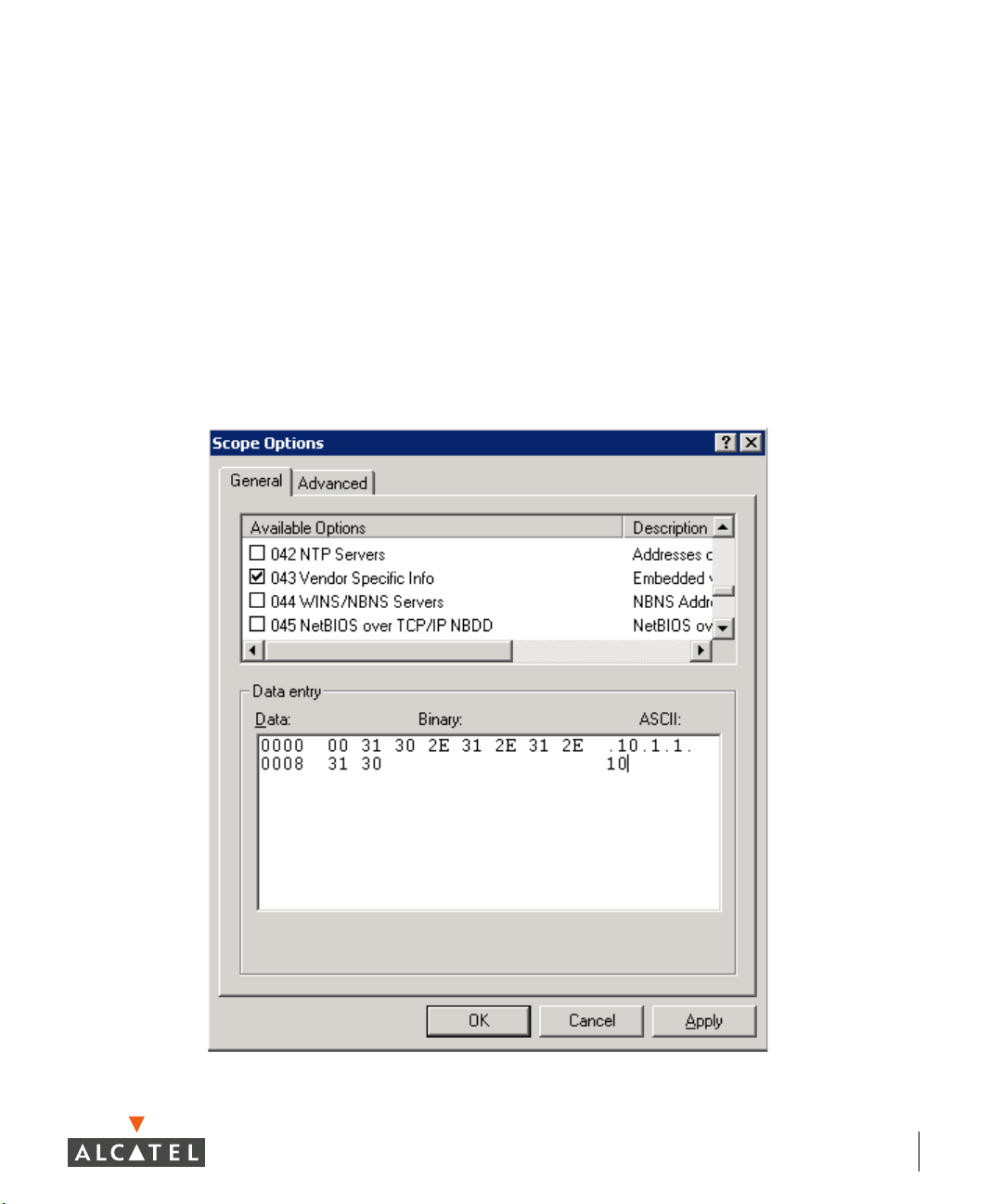
DHCP Configuration
DHCP servers may be configured to return Alcatel vendor-specific options to
APs. The vendor class identifier is “AlcatelAP”, and the vendor-specific option
code is 43. A sample configuration for the open-source ISC DHCP server
follows. In this example, the Alcatel switch is located at IP address 10.1.1.10.
option serverip code 43 = ip-address;
class "vendor-class" {
match option vendor-class-identifier;
}
.
.
.
subnet 10.200.10.0 netmask 255.255.255.0 {
default-lease-time 200;
max-lease-time 200;
option subnet-mask 255.255.255.0;
option routers 10.200.10.1;
option domain-name-servers 10.4.0.12;
option domain-name "test.com";
subclass "vendor-class" "AlcatelAP" {
option vendor-class-identifier "AlcatelAP";
6 Part 031652-00 May 2005
Page 29
Chapter 1
option serverip 10.1.1.10;
}
range 10.200.10.200 10.200.10.252;
}
To configure Microsoft’s DHCP server for this feature:
1. Add an “option 43” entry to the desired DHCP scope that contains the IP
address of the Alcatel switch in text. An example of this is shown in the
following figure.
Overview 7
Page 30

OmniAccess Reference: AOS-W System Reference
2. From a command prompt, enter:
c:\>netsh
netsh>dhcp
netsh dhcp>server \\<server_machine_name
netsh dhcp>add optiondef 60 AlcatelAP String 0 comment=AlcatelSupport netsh
dhcp>set optionvalue 60 STRING AlcatelAP
netsh dhcp>exit
>
Multicast Configuration
A network supporting IP multicast must be in place to make use of the ADP
multicast capability. To configure the Alcatel switch for multicast, enter:
(config) # adp discovery enable
(config) # adp igmp-join enable
This configuration will cause the Alcatel switch to send an IGMPv2 join
message for multicast group 224.0.82.11.
8 Part 031652-00 May 2005
Page 31

CHAPTER 2
Management Options
AOS-W provides a number of methods for managing your Alcatel
Wireless LAN Switch.
Command-Line Interface
The Command-Line Interface (CLI) provides the most direct
method for configuring the switch and collecting system
information. The CLI has the following features:
z Accessible from a local console terminal
z Optionally available through Telnet or SSH to local manage-
ment console or remote network connection
z Comprehensive, industry-standard command system
See “Command Line Basics” on page 13 for more information.
Web Interface
The Web interface provides an intuitive, graphical interface to
special configuration and design tools. The Web interface
provides the following:
z Compatible with a standard Web browser
1
z Accessible from the local management console or remote net-
work connection
1.AOS-W requires Internet Explorer 6.0 or higher. Other browsers may work but
with limited functionality and are therefore not officially supported.
Management Options 9
Page 32

OmniAccess Reference: AOS-W System Reference
z Configure and manage wireless intrusion prevention and performance poli-
cies
z Monitor the state and performance of the Wireless LAN
z Perform a site survey to assist deployment of Alcatel Access Points and Air
Monitors
z Monitor air interface security and performance events
z AP triangulation
General Screen Elements
When Web UI is started after a successful login, the browser window will
show the default page: the Monitor Summary. For ease of navigation, all of the
Web UI pages have a similar page structure:
Selected
Too l
Too l B ar
Logout
Button
Page
Display
Selected
Page
Page
Tree
FIGURE 2-1 Web UI Page Elements
z Tool Bar–This contains buttons for the various tools available in the Web UI
software. Click on a button to select the tool.
z Selected Tool–This displays the name of the currently selected tool.
10 Part 031652-00 May 2005
Page 33

Chapter 2
z Page Tree–Each tool has its own information or configuration pages and
sub-pages.
The page tree lists all of the pages available when using the currently selected
tool. You can navigate to any of the listed pages by clicking on the page name.
NOTE—Some of the items in the page tree are merely headings for their sub-pages and cannot be selected. Selectable pages
become highlighted when the mouse cursor is placed over them. Non-selectable items do not react.
z Selected Page–The name of the currently selected page is highlighted in
the page tree.
z Page Display–This area displays all the information and/or input fields rele-
vant to the current page of the current tool.
z Logout Button–Click on this button to end your Web UI session.
Page Elements
Each tool in the Web UI has its own unique information or configuration
pages, each with specialized data and control fields. Some of the page items
appear on multiple pages in multiple tools and provide a similar navigation or
configuration function in each.
Navigation Items
z
Scroll-bars–In some cases, there will be more fields than can be conveniently displayed on one window. When this occurs, standard Windows
scroll-bars will be available to let you access the rest of the page.
z Page Tabs–Some pages feature a row of tabs near the top of the page dis-
play area. Each tab represents a different form available from the current
page.
z Links–Items which are underlined are linked to other pages. By clicking on
the item, the relevant item’s configuration or information page will be displayed.
Fields
z
Information Fields–These fields are used only for displaying information.
The data in these fields cannot be edited directly on the displayed screen.
z Data Entry Fields–Boxed text fields contain user-configurable data. To enter
or edit the information, click inside the field box.
z Pull-down Menus–These fields allow you to select an item from a preset
list. The currently selected item is displayed in the box. When the arrow
button is selected, a list of available options appears. You can change the
current selection by clicking on any item in the options list.
z Scrolling Menus–These fields allow you to select an item from a preset list.
Use the scroll arrows to view the available options. To select a specific
item from the list, click on the item when displayed.
Management Options 11
Page 34

OmniAccess Reference: AOS-W System Reference
z Check Boxes–Represented as small squares in front of the item text. These
fields allow you to turn items on or off by clicking on the check box. A feature or option will be turned on, selected, or enabled (as appropriate) when
the box is checked. A feature or option will be turned off, unselected, or
disabled when the box is empty.
z Radio Buttons–Represented as small circles in front of the item text. When
a group of these items appears together, only one can be selected at any
given time. An item is selected when its circle is filled. An item is unselected when the circle is empty.
Action Buttons
The following buttons are generally available on configuration pages.
z Apply–Accept all configuration changes made on the current page and send
the completed form to the Wireless LAN switch.
z Clear–Reset all options on the current page to their last applied or saved
settings.
z Add–Add a new item to the current page. This generally displays a set of
relevant configuration fields for the added item.
z Edit–Edit the configuration of the selected item.
z Delete–Remove the selected item from the page configuration.
z Save Configuration–Save all applied configuration changes made since dur-
ing this configuration session. Saved settings will be retained when the
switch is rebooted or turned off. Unsaved configuration changes will be
permanently lost.
12 Part 031652-00 May 2005
Page 35

CHAPTER 3
Command Line Basics
The Command Line Interface (CLI) is the most direct and
comprehensive method for managing the Alcatel Wireless LAN
Switch. The CLI can be used to gather information about the
switch configuration, collect switch performance statistics, and
make configuration changes.
The CLI uses a simple, text-based interface with a Cisco-like
command structure. The format is compatible with standard
terminals and PC terminal emulation software, and can be
accessed locally or over the network using Telnet.
Connecting to the Switch
Local Serial Console
The CLI is always available using a local terminal or a computer
running terminal emulation software. Attach your terminal directly
to the serial port on the supervisor card and set the terminal to
use the following communications setting:
TABLE 3-1 Console Terminal Settings
Baud Rate Data Bits Parity Stop Bits Flow Control
9600 8 None 1 None
Press <Enter> a few times.to establish the connection and access
the login prompt.
OTE—The serial port accepts an RS-232 serial cable with an
N
RJ-45 male connector (see the Alcatel 6000 Installation Guide
for more port and cable specifications).
Command Line Basics 13
Page 36

OmniAccess Reference: AOS-W System Reference
Local or Remote Telnet
If properly set up, the CLI can be accessed locally or remotely using Telnet. You
can use Telnet (or SSH or the Web GUI) to access any IP interface on an Alcatel
Wireless LAN switch.
Enabling Telnet Access
The default CLI management method is SSH. To enable Telnet, from
configuration terminal mode, enter:
> telnet cli
Telnet access requires that the switch management interface and default
gateway be defined. This is usually done during initial setup (see Step 3 on
page 11) but can also be done manually using the local serial console:
1
Use the local serial console to log in as the administrator.
2
Enter configuration mode and select the management interface
sub-mode:
(Alcatel) # configure terminal
Enter Configuration commands, one per line. End with CNTL/Z
(Alcatel) (config) # interface mgmt
3
Set the management interface IP address and subnet mask:
(Alcatel) (config-mgmt)# ip address
The management interface is active by default.
4
Exit the sub-mode:
<IP address> <subnet mask>
(Alcatel) (config-mgmt)# exit
5
Configure the default gateway for the management interface:
(Alcatel) (config) # ip default-gateway
NOTE—If no default gateway is configured, remote access is available only for
devices on the same subnet as the management interface.
<next hop>
mgmt
14 Part 031652-00 May 2005
Page 37

Chapter 3
Using Telnet to Connect
Use a Telnet client on your management workstation to connect to the Alcatel
Wireless LAN Switch management interface IP address. The connection
command may vary depending on the specific software used, but commonly
appears as follows:
> telnet
When the connection is established, the login prompt will be displayed.
<management interface IP address>
Logging In
Once connected, the system displays its host name (Alcatel if not
configured), followed by the log in prompts. Log in using the administrator
account. For example:
(Alcatel)
user: admin
password: admin
As shown above, the default administrator user name is admin, and the default
password is also admin. If the password has been changed, use the correct
one. When properly logged in, the user mode CLI prompt will be displayed:
(
host
) > _
(password is displayed as asterisks)
Access Modes
Once logged in, there are two levels of access to the switch: user mode and
privileged mode.
z User Mode
User mode provides only limited access for basic operational testing, such as
running ping and traceroute. User mode is entered immediately upon login and
is shown with the following prompt:
(
host
) >
where host is the host name of the switch if configured, or Alcatel if not
configured.
User mode commands are documented starting on page 819.
Command Line Basics 15
Page 38

OmniAccess Reference: AOS-W System Reference
z Privileged Mode
All configuration and management functions are available in privileged mode. To
move from user mode to privileged mode requires an additional password:
(Alcatel) > enable
<privileged password>
(Alcatel) #
When successfully promoted to privileged mode, the > prompt is replaced by the
# prompt.
The numerous privileged mode commands are divided into groups according to
their context as outlined in the next section.
Command Context
The commands available while in the privileged mode are divided into a number
of context groups:
z Action Commands
The Action Commands take effect as soon as they are entered. They affect the
current behavior or operation of the switch, but are not saved as part of the
permanent configuration.
The Immediate commands are documented starting on page 819.
z Master Commands
One Alcatel Wireless LAN Switch on the network is responsible for loading
software and configuration files to the Alcatel Access Points and for managing
enhanced Wireless LAN switching features (such as air management and
wireless load balancing).
In a system with only one switch, the single switch always acts as the master.
In a system with more than one switch, one (and only one) switch is selected as
the master.
The master switch has an extended command set for handling Access Points
and enhanced Wireless LAN features. The master commands are documented
starting on page 797.
z Local Commands
In a system with two or more switches, only one acts as the master. The others
act as local switches with a more limited command set.
Commands on local switches mostly affect Layer 2/Layer 3 configuration (such
as physical ports and routing interfaces). The local commands are documented
starting on page 445.
16 Part 031652-00 May 2005
Page 39

z Show Commands
The show commands list information about the switch configuration and
performance and are invaluable for debugging system configuration. The show
commands are documented starting on page 833.
Saving Configuration Changes
Configuration changes made using the CLI affect only the current state of the
switch. Unless saved, the changes will be lost when the system is rebooted.
To save your changes so that they will be retained after a reboot, use the
following privileged mode CLI command:
(Alcatel) # write memory
Saving Configuration...
Saved Configuration
Viewing the Configuration
Chapter 3
There are two configuration images which can be viewed from the CLI:
z startup-config
This holds the configuration options which will be used the next time the
system is rebooted. It contains all the options last saved using the write memory
command. Presently unsaved changes are not included.
To view the startup-config, use the following command:
(Alcatel) # show startup-config
z running-config
This holds the current switch configuration, including all pending changes
which have yet to be saved.
To view the running-config, use the following command:
(Alcatel) # show running-config
Both configurations can also be saved to a file or sent to a TFTP server for
backup or transfer to another system. See “Making Configuration Backups”
on page 126 for details.
Command Line Basics 17
Page 40

OmniAccess Reference: AOS-W System Reference
Shortcuts
Command Completion
To make command input easier, you can usually abbreviate each key word in
the command. You need type only enough of each keyword to distinguish it
from similar commands. For example:
(Alcatel) # configure terminal
could also be entered as:
(Alcatel) # con t
Three characters (con) represent the shortest abbreviation allowed for
configure. Typing only c or co would not work because there are other
commands (like copy) which also begin with those letters. The configure
command is the only one that begins with con.
As you type, you can press the spacebar or tab to move to the next keyword.
The system will then attempt to expand the abbreviation for you. If there is
only command keyword that matches the abbreviation, it will be filled in for
you automatically. If the abbreviation is too vague (too few characters), the
cursor will not advance and you must type more characters or use the help
feature to list the matching commands.
Command Help
You can use the question mark (?) to get various types of command help.
List Available Commands
When typed at the beginning of a line, the question mark lists all the
commands available in your current mode or sub-mode. A brief explanation
follows each command. For example:
(
host
) > ?
enable Turn on Privileged commands
logout Exit this session. Any unsaved changes are lost.
ping Send ICMP echo packets to a specified IP address.
traceroute Trace route to specified IP address.
18 Part 031652-00 May 2005
Page 41

Chapter 3
List Matching Commands
When typed at the end of a possible command or abbreviation, the question
mark lists the commands that match (if any). For example:
(
host
) # c?
clear Clear configuration
clock Configure the system clock
configure Configuration Commands
copy Copy Files
If more than one item is shown, type more of the keyword characters to
distinguish your choice. However, if only one item is listed, the keyword or
abbreviation is valid and you can press tab or the spacebar to advance to the
next keyword.
List Next Parameter
When typed in place of a parameter, the question mark list the available
options. For example:
(
host
) # write ?
erase Erase and start from scratch
file Write to a file in the file system
memory Write to memory
terminal Write to terminal
<Enter>
The <Enter> entry (“carriage return,” or the enter key) indicates that the
command can be entered without additional parameters. Any other
parameters are optional.
Command History
The system records your most recently entered commands. You can review
the history of your actions, or reissue a recent command easily, without
having to retype it.
To view items in the command history, use the <up arrow> to move back
through the list and <down arrow> key to forward. To reissue a specific
command, press <enter> when it appears. You can even use the command line
editing feature to make changes to the command prior to entering it.
Command Line Basics 19
Page 42

OmniAccess Reference: AOS-W System Reference
Command Line Editing
The command line editing feature allows you to make corrections or changes
to a command without retyping. Ta b l e 3 -2 lists the editing controls:
TABLE 3-2 Line Editing Keys
Key Effect Description
<Ctrl-a> Home Move the cursor to the beginning of the line.
<Ctrl-b> or
<left arrow>
<Ctrl-d> Delete
<Ctrl-e> End Move the cursor to the end of the line.
<Ctrl-f> or
<right
arrow>
<Ctrl-k> Kill Right Delete all characters to the right of the cursor.
<Ctrl-n> or
<down
arrow>
<Ctrl-p> or
<up arrow>
<Ctrl-t> Transpose Swap the character to the left of the cursor with
<Ctrl-u> Clear Clear the line.
<Ctrl-w> Delete
<Ctrl-x> Kill Left Delete all characters to the left of the cursor.
Back Move the cursor one character left.
Delete the character to the right of the cursor.
Right
Forward Move the cursor one character right.
Next Display the next command in the command
history.
Previous Display the previous command in the command
history.
the character to the right of the cursor.
Delete the characters from the cursor up to and
Word
including the first space encountered.
Alpha-numeric characters are always inserted into the line at the cursor
position.
Command Syntax
CLI commands use basic notations for the parameters that modify a
command. These include:
z Brackets [ ]—denotes that the object(s) inside are optional.
z Braces { }—denotes that the object(s) inside are required. If more than one
object is included inside a brace, one of the objects must be specified.
z Angles < >—denotes the parameter is required and must be specified.
20 Part 031652-00 May 2005
Page 43

Chapter 3
z Pipe | —denotes a two or more parameters, separated one from the other
by the | symbol.
For example:
crypto ipsec transform-set
<set name>
{esp-des|esp-3des}
{esp-md5-hmac|esp-sha-hmac}
means you have to specify the set name, then choose either esp-des or
esp3des, then choose either esp-md5-hmac or esp-sha-hmac.
client configuration dns
means you have to specify the server1 address, but you do not have to specify
anything about server2.
In general, italics indicates a value you have to enter. For example address
means you have to specify an IP address or MAC address. You cannot just
enter “address”.
Bold, like no, means you enter that string. In this case, just type “no”.
<server1 address> [<server2 address>
|no]
Command Line Basics 21
Page 44

OmniAccess Reference: AOS-W System Reference
22 Part 031652-00 May 2005
Page 45

Part
2
Design and
Planning
23
Page 46

OmniAccess Reference: AOS-W System Reference
24 Part 031652-00 May 2005
Page 47

CHAPTER 4
RF Design
The Alcatel RF Plan Tool
RF Plan is a three-dimensional wireless deployment modeling tool
that enables Network Administrators to design an efficient
Wireless Local Area Network (Wireless LAN) for their corporate
environment, optimizing coverage and performance, and
eliminating complicated Wireless LAN network setup.
RF Plan provides the following critical functionality:
z Defines Wireless LAN coverage
z Defines Wireless LAN environment security coverage
z Assesses equipment requirements
z Optimizes radio resources
z Creates an exportable Wireless LAN profile that may be
imported into an Alcatel switch and be used to configure and
deploy the Wireless LAN.
z AP validation
z Rogue AP triangulation
RF Plan provides a view of each floor, allowing Network
Administrators to specify how Wi-Fi coverage should be
provided. RF Plan then provides coverage maps and AP/AM
placement locations.
Unlike other static site survey tools that require
administrators to have intricate knowledge of building
materials and other potential Radio Frequency (RF)
hazards, RF Plan calibrates coverage on the fly
through a sophisticated RF calibration algorithm. This
real-time calibration lets administrators characterize
the indoor propagation of RF signals in order to determine the best channel and transmission power set-
RF Design 25
Page 48

OmniAccess Reference: AOS-W System Reference
tings for each AP. Real-time calibration can be automatically
programmed or manually undertaken at any time in order to
quickly adapt to changes in the wireless environment.
Getting Started
The RF Plan application is available on the Alcatel Wireless LAN switch or as a
standalone Windows application. This chapter describes the functionality for
both versions of RF Plan. Where there are differences in how the two
difference versions are used, they are noted.
System Requirements for Standalone RF Plan
The standalone Alcatel RF Plan application requires:
z Windows 2000 or Windows XP
z Microsoft Internet Explorer 6.0 or later
z Macromedia Flash 6.0 or later plug-in for Internet Explorer
z Intel Pentium® III 800Mhz (min) or equivalent
z 128MB RAM
1
z 10MB available hard drive space
Installing RF Plan
To install RF Plan, follow the three steps below:
NOTE—RF Plan only runs on Windows 2000 and WindowsXP.
1. Locate the file named Alcatel RF Plan.zip.
2. Unzip the file.
3. Launch setup.exe.
By default, the installer places the files in C:\Program Files\Alcatel RF Plan
directory. To install the application in a different directory, specify the
appropriate location.
1.Other browsers may work with AOS-W but with limited capability and are therefore unsupported.
26 Part 031652-00 May 2005
Page 49

Launching RF Plan
To open RF Plan select: Start > All Programs > Alcatel Offline RF Plan> Alcatel RF
Plan
.
RF Plan Basics
Page Summary
The following is a brief summary of the functionality of each of the pages in
RF Plan.
z Building List Page The Building List page provides a list of
buildings that you have created and saved.
You may use this page to add or delete
buildings from you saved database. You may
also import or export buildings here.
z Building Overview Page The Building Overview page allows you to see
all the dimensional data and modeling
parameters for your buildings.
Chapter 4
z Building Specification
Page
Specify the dimensions of your building and
name it in the Building Specifications page.
z AP Modeling Page Specify the AP Modeling parameters on this
page.
z AM Modeling Page Specify the AM Modeling parameters on this
page.
z Import and Export Use this page to import and export building
database files.
z Planning Floors Page The Planning Floors page allows you to see
approximate coverages of APs and AMs, as
well as any floor plans you may have imported
as background images.
z Floor Editor Page Use this page to upload background images
for each floor, name the floor and delete floors.
NOTE—You cannot have more than one
browser window open when you are trying to
upload images.
RF Design 27
Page 50

OmniAccess Reference: AOS-W System Reference
z Area Editor Page Use this page to specify areas on each floor
where coverage is not desirable or where
Access Points/Air Monitors may not be
physically deployed.
z Access Editor Page Use this page to manually create, position, or
configure Access Points or Air Monitors.
z AP Plan The AP Plan page is used to initialize the
position of Access Points and launch RF
Plan’s positioning algorithm.
z AM Plan The AP Plan page is used to initialize the
position of Air Monitors and launch RF Plan’s
positioning algorithm.
Page Fields
Each tool in the RF Plan has its own unique information or configuration pages,
each with specialized data and control fields. Some of the page items appear
on multiple pages and provide a similar navigation or configuration function in
each.
z Information Fields–These fields are used only for displaying information.
The data in these fields cannot be edited directly on the displayed screen.
z Data Entry Fields–Boxed text fields contain user-configurable data. To enter
or edit the information, click inside the field box.
z Pull-down Menus–These fields allow you to select an item from a preset
list. The currently selected item is displayed in the box. When the arrow
button is selected, a list of available options appears. You can change the
current selection by clicking on any item in the options list.
z Scrolling Menus–These fields allow you to select an item from a preset list.
Use the scroll arrows to view the available options. To select a specific item
from the list, click on the item when displayed.
z Check Boxes–These fields are represented as small squares in front of the
item text. These fields allow you to turn items on or off by clicking on the
check box. A feature or option will be turned on, selected, or enabled (as
appropriate) when the box is checked. A feature or option will be turned
off, unselected, or disabled when the box is empty.
z Radio Buttons–These fields are represented as small circles in front of the
item text. When a group of these items appears together, only one can be
selected at any given time. An item is selected when its circle is filled. An
item is unselected when the circle is empty.
28 Part 031652-00 May 2005
Page 51

Chapter 4
Navigation
The RF Plan tool is a wizard in that it logically guides you through the process
of defining radio coverage for all the buildings on your campus. The left pane
of the wizard screens shows the progression you follow each time you click
Apply. The button on the top, right corner also takes you to the next logical
step. You can also click the link on the left pane to go to any screen in the
wizard.
Regardless of your current location, you can always return to the opening
window by clicking Plan on the menu bar.
Applying and Saving
When you edit information on any of the RF Plan pages you need to apply that
information before it is effective. However, applying the information doesn’t
save it to your hard drive. You must click on the Save button to permanently
save the information.
The following buttons are generally available on configuration pages.
z Apply–Accept all configuration changes made on the current page (does
not save changes).
z Save–Save all applied configuration changes made since during this config-
uration session to a database file. Unsaved configuration changes will be
lost when the RF Plan tool is exited.
NOTE—Always Apply. If you advance to the next step without clicking on the
Apply button the information will be lost.
Next Step Button
RF Plan will sequence you through all the pages as you setup your Wireless
LAN. When you have finished entering the information for each page, click
Next Step located in the upper right-hand portion of the page.
RF Design 29
Page 52

OmniAccess Reference: AOS-W System Reference
Opening Screen
When RF Plan opens, the browser window will show the default page: the RF
Plan Building List page.
Building List Page
The Building list page contains all the buildings you have defined using the RF
Plan software. The first time you run the application, there should be no
buildings in the list.
FIGURE 4-1 Building List Page
z New Building Use this button to create a new building. See
“Adding a New Building to the Plan” on page 32.
z Edit Buildings Use this button to edit existing buildings in the
building list. See “Adding a New Building to the
Plan” on page 32
z Delete Buildings Use this button to delete existing buildings in the
building list.
z Export Use this button to export a database file with all
the specifications and background images of a
selected building(s) in the building list. See “Import
and Export” on page 39
z Import Use this button to import database files defining
pre-existing buildings into the RF Plan building list.
See “Import and Export” on page 39
z Locate Use this button to find the specified building.
30 Part 031652-00 May 2005
Page 53

z Search When the database of buildings has been created,
use this feature to find a specific building, on a
specific campus, or search for a name string.
You may add, edit, and delete buildings using this window. You may also
import and export buildings using the import and export buttons.
Using RF Plan
Task Overview
Before you begin take a minute to review this section, it explains the general
steps in the order they should be taken to create a building and plan the
Wireless LAN for it.
z Gather information about your building’s dimensions and floor plan.
z Determine the level of coverage you want for your Access Points and Air
Monitors.
z Create a new building and add its dimensions.
z Enter the parameters of your Access Point coverage.
Chapter 4
z Enter the parameters of your Air Monitor coverage.
z Add floors to your building and import the floor plans.
z Define special areas.
z Generate suggested AP and AM tables by executing the AP/AM Plan fea-
tures.
z Export the building.
RF Design 31
Page 54

OmniAccess Reference: AOS-W System Reference
Planning Requirements
You should collect the following information before beginning to plan your
network. Having the information below readily available will expedite your
planning efforts.
z Building Dimensions
z Number of floors
z Distance between floors
z Number of users and number of users per AP
z Radio type(s)
z Overlap Factor
z Desired data rates for access points
z Desired monitoring rates for air monitors
z Areas of your building(s) that you don’t necessarily want coverage
z Areas of your building(s) where you don’t want to, or cannot, deploy an
AP or AM
z Any area where you want to deploy a fixed AP or AM.
Building Dimensions
Height: Width:
Number of Floors:
User Information
Number of Users: Users per AP:
Radio Types:
Overlap Factor:
AP Desired Rates
802.11b|g: 802.11a:
AM Desired Rates
802.11b|g: 802.11a:
Don’t Care/Deploy Areas
Adding a New Building to the Plan
To define a new building, click New Building.
32 Part 031652-00 May 2005
Page 55

Chapter 4
The Overview page shows the default values for your new building, most of
which you can change in the following pages.
On Building Overview Page you will be able to view the specifications for the
following:
z Your buildings dimensions.
z Access Point modeling parameters.
z Air Monitor modeling parameters.
To define your building, click
displays.
Building Dimensions. The Specification page
RF Design 33
Page 56

OmniAccess Reference: AOS-W System Reference
Building Specification Page
The Building Specification Page enables you to specify the identity of your
building and its dimensions.
Enter the appropriate values in the text boxes in the Dimension window.
z Building ID This consists of two decimal numbers separated by a
dot. The first is the campus ID. The campus ID will
always be “1” if there is only one campus. The second is
the building number.
The valid range for these fields is any integer from 1 to
255.
z Building Name Enter a user friendly name for the building.
The Building Name may be an alpha-numeric string up to
64 characters in length.
z Width and
Height
z Inter-floor
Height
34 Part 031652-00 May 2005
Enter the rectangular exterior dimensions of the
building.
The valid range for this field is any integer from 1 to a
value corresponding to .
This is the distance between floor surfaces in the
building.
The valid range for this field is any integer from 1 to a
value corresponding to .
NOTE—This is NOT the distance from floor to ceiling. Some
buildings have a large space between the interior ceilings
and the floor above.
112×10
1
×10
12
Page 57

z Floors Enter the number of floors in your building here.
Chapter 4
The valid range for this field is any integer from 1 to a
value corresponding to .
1
×10
12
z Units Specify the units of measurement for the dimensions
you specified on the page. The choices are feet and
meters.
A Word About Building Dimensions
The dimensions you specify for building width and height should be the major
dimensions (maximum height and width) of the overall footprint of the
building as illustrated below.
Maximum Width
Maximum Height
When height and width are specified, RF Plan creates a rectangular area in the
Planning feature pages that represent the overall area covered by the building.
You will need to import an appropriate background image (see, “Floor Editor
Page” on page 44.) to aid you in defining areas that don’t require coverage or
areas in which you do not wish to deploy Access Points and Air Monitors
(see,“Area Editor Page” on page 45).
Define your first building on this campus and click
Apply. The AM Modeling
page displays.
RF Design 35
Page 58

OmniAccess Reference: AOS-W System Reference
AP Modeling Page
The AP Modeling page allows you to specify all the information necessary for
RF Plan to determine the appropriate placement of your APs.
Controls on this page allow you to select or control the following functions:
z Radio Type Use this pull-down menu to specify the radio type in the
appropriate combination of a, b, and or g configuration.
z AP Type Specify AP 52 or AP 60.
z Coverage Use this option to let RF Plan automatically determine
the number of APs based on desired data rates and the
configuration of your building. The desired rate is
selectable from 1 to 54 Mbps in both the Coverage and
Capacity models.
z Capacity Use this option to let RF Plan determine the number of
APs based upon the total number of users, ratio of users
to APs, and desired data rates. The desired rate is
selectable from 1 to 54 Mbps in both the Coverage and
Capacity models.
z Custom Use this option to simply specify a fixed number of APs.
z Overlap Factor Use this field and pull-down to specify an overlap factor.
z Rates Use these pull-down to specify the data rates desired on
your Access Points.
z Users/AP Selectable for Capacity or Custom models.
z APs Selectable for Capacity or Custom models.
36 Part 031652-00 May 2005
Page 59

Chapter 4
Radio Type
Specify the radio type(s) of your APs using the pull-down Radio Type menu on
the Modeling Parameters page.
Available Radio Type Choices:
z 801.11a 5GHz, Orthogonal Frequency Division Multiplexing
(OFDM) with data rates up to 54Mbps.
z 802.11b 2.4GHz, Direct Spread Spectrum (DSSS) multiplexing
with data rates up to 11Mbps.
z 802.11g 2.4GHZ, OFDM/CCK (Complementary Code Keying)
with data rates up to 54Mbps.
Overlap Factor
The Overlap Factor is the amount of signal area overlap that you want when
the APs are operating. Overlap is important if an AP fails. It allows the
network to self-heal with adjacent APs powering up to assume some of the
load from the failed device. Although there may be no holes in coverage in this
scenario, there will likely be a loss of throughput. Increasing the overlap will
allow for higher throughputs when an AP has failed and will allow for future
capacity as the number of users increases.
The valid range of values for the overlap factor are from 100% to 1000%.
Users
NOTE—The Users text boxes are active only when the Capacity model is selected.
Enter the number of users you expect to have on your Wireless LAN in the
Users text box. Enter the number of users per access point you expect in the
Users/AP text box.
The numbers entered in the these two text boxes must be no-zero integers
between 1-255 inclusive.
Rates
NOTE—The Rate pull-down menus are active only when the Coverage or Capacity
design models are selected.
Select the desired data rates from the pull-down menus for 802.11b/g and
802.11a.
High data transmission rates will require an increased number of AP to be
placed in your building. You should carefully evaluate your user’s data rate
needs.
RF Design 37
Page 60

OmniAccess Reference: AOS-W System Reference
Click Apply and the AM Modeling page displays.
AM Modeling Page
The AM Modeling page allows you to specify all the information necessary for
RF Plan to determine the appropriate placement of your AMs.
Controls on this page allow you to select or control the following functions:
z Monitor Rate Use this pull-down menu to specify the desired monitor
rate for your Air Monitors.
z AMs Use this field to manually specify the number of Air
Monitors to deploy (Custom Model only).
z Design Model Use these radio buttons to specify a design model to
use in the placement of Air Monitors.
Design Models
Two radio buttons on the page allow you to control the kind of model which
will be used to determine the number and type of APs.
Design Model Radio Button Options:
z Coverage Use this option to let RF Plan automatically determine
the number of AMs based on desired monitor rates and
the configuration of your building.
Desired rate is selectable from 1 to 54 Mbps in the
Coverage model.
z Custom Use this option to simply specify a fixed number of
AMs. When the AM Plan portion of RF Plan is executed,
RF Plan will make an even distribution of the AMs.
38 Part 031652-00 May 2005
Page 61

Chapter 4
NOTE—The monitor rates you select for the AMs should be less than the data rates
you selected for the APs. If you set the rate for the AMs at a value equal to that
specified for the corresponding PHY type AP, RF Plan will allocate one AM per
AP. If you specify a monitor rate larger than the data rate, RF Plan will allocate
more than one AM per AP.
Monitor Rates
Use the drop down menus to select the desired monitor rates for 802.11b/g
and 802.11a air monitors.
NOTE—This option is available only when the coverage design model is selected.
Import and Export
RF Plan allows you to import and export files that define the parameters of
your buildings. The files that you import and export are XML files and
depending on how many floors your buildings have, and particularly how
many background images you have for your floors, the XML files may be quite
large. (See “Background Images” on page 44.)
Buildings exported from RF Plan will be imported into an Alcatel switch and
used by the version of RF Plan that is integrated into the Web UI Software.
The exported building file contains all the data about the building(s) you
created using RF Plan. The integrated RF Plan in Web UI gives you the ability
to automatically configure the APs and AMs that are actually connected to the
switch using the Suggested AP and Suggested AM tables created by RF Plan.
(See, “AP Plan” on page 49 and “AM Plan” on page 51.)
Import Buildings
The Import Buildings page allows you to import configuration information
from an existing Alcatel switch so you can modify it for use on another switch
or in an another building.
Only XML files exported from an Alcatel switch or from Alcatel RF Plan may be
imported into RF Plan.
RF Design 39
Page 62

OmniAccess Reference: AOS-W System Reference
NOTE—Importing any other file, including XML files from other applications,
may result in unpredictable results.
Any file you wish to import must be in the C:\Program Files\Alcatel RF
Plan\data\ path. You can not specify any other path in the RF Plan Import
Buildings dialog.
Export Buildings
The Export Buildings page allows you to export the configuration of the
Wireless LAN you just created so that it may be imported into and used to
automatically configure your Alcatel switches.
Files exported from RF Plan will be placed in the C:\Program Files\Alcatel RF
Plan\data\ directory on your hard drive.
When exporting a building file it is recommended that you check the Include
Images check box.
When naming your exported file, be sure to give the file the .XML file
extension.
Example: My_Building.XML
40 Part 031652-00 May 2005
Page 63

Planning Pages
Planning Floors Page
Chapter 4
The Planning Floors page enables you to see what the footprint of your floors
look like. You can select or adjust the following features on the Planning
Floors Page.
z Zoom Use this pull-down menu or type a zoom factor in
the text field to increase or decrease the size of the
displayed floor area.
z Approximate Cover-
age Map (select
radio type)
Use this pull-down to select a particular radio type
for which to show estimated coverage.
z Coverage Rate Use this pull-down to modify the coverage areas
based on a different data rate.
z Floor Editor Click on this link to launch the Floor Editor. See
“Floor Editor Page” on page 44.
z Area Editor Click on this link to launch the Area Editor. See
“Area Editor Page” on page 45.
z Access Point Editor Click on this link to launch the Access Point Editor.
See “Access Editor Page” on page 46.
RF Design 41
Page 64

OmniAccess Reference: AOS-W System Reference
Zoom
The Zoom control sets the viewing size of the floor image. It is adjustable in
finite views from 10% to 1000%. You may select a value from the pull-down
zoom menu or specify a value in the text box to the left of the pull-down. When
you specify a value, RF Plan adjusts the values in the pull-down to display a set
of values both above and below the value you typed in the text box.
Coverage
Select a radio type from the Coverage pull-down menu to view the
approximate coverage area for each of the APs that RF Plan has deployed in AP
Plan or AM Plan. Adjusting the Coverage values will help you understand how
the AP coverage works in your building.
NOTE—You will not see coverage circles displayed here until you have executed either
an AP Plan or an AM Plan.
42 Part 031652-00 May 2005
Page 65

Chapter 4
Coverage Rate
Adjusting the coverage rate will also affect the size of the coverage circles for
AMs. Adjusting the rate values will help you understand how the coverage
works in your proposed building.
Reading Coverage Maps
Under some conditions, AP or AM signal strengths show in coverage maps
may not be reported accurately. One condition is a single AP or AM in the
corner of a building. The coverage map may show the signal strength
extending well outside the building. However, if the signal encounters nearby
interference in the building, the signal strenght may be much weaker in the
area of the interference. This area of weakened signal strength will likely not
be reflected in the coverage map.
Another condition that renders the coverage map to be somewhat inaccurate
is an environment in which multiple APs or AMs differ substantially in signal
strength. In this mixed environment, the coverage map will average signal
strengths of the devices and may report strengths slightly less than the actual
signal strength of the stronger devices and slightly greater than that of the
weaker devices.
Per Floor Recap
Between each floor display, RF Plan lists the APs and AMs defined for the
floor.
RF Design 43
Page 66

OmniAccess Reference: AOS-W System Reference
Floor Editor Page
Click Edit Floor to display the Floor Editor which allows you to specify the
background image, and name the floor.
Naming
You may name the floor anything you choose as long as the name is an
alpha-numeric string with a maximum length of 64 characters. The name you
specify appears just to the right of the Floor Number displayed just above the
background image in the Planning view.
Background Images
A background image (floor plan image) may be imported into RF Plan for each
floor. A background image is extremely helpful when specifying areas where
coverage is not desired or areas where an AP/AM is not to be physically
deployed.
Select a background image using the Browse button on the Floor Editor Dialog.
z File Type and Size
Background images must be JPEG format and may not exceed 2048 X 2048
pixels in size. Attempting to import a file with a larger pixel footprint than that
specified here will result in the image not scaling to fit the image area in the
floor display area.
NOTE—Because the background images for your floors are embedded in the XML file
that defines your building you should strongly consider minimizing the file size of
the JPEGs you use for your backgrounds. You can minimize the file size by selecting the maximum compression (lowest quality) in most graphics programs.
z Image Scaling
Images are scaled (stretched) to fit the display area. The display area aspect
ratio is determined by the building dimensions specified on the Dimension
page.
44 Part 031652-00 May 2005
Page 67

Chapter 4
Area Editor Page
The area editor allows you to specify areas on your buildings floors where you
either do not care about coverage, or where you do not want to place an AP or
AM.
Open the Area Editor by clicking on the New link in the Areas field just below
the area where the background image is displayed.
Area Editor “New” Link
You specify these areas by placing them on top of the background image
using the Area Editor.
Naming
You may name an area using an alpha-numeric string of characters with a
maximum length of 64 characters. You should give areas some meaningful
name so that they are easily identified.
Locating and Sizing
You may specify absolute coordinates for the lower left corner and upper right
corner of the box that represents the area you are defining. The datum for
measurement is the lower left corner of the rectangular display area that
represents your building’s footprint. The coordinates of the upper right-hand
corner of the display area are the absolute (no unit of measure) values of the
dimensions you gave your building when you defined it with the dimension
feature.
For example: If you defined your building to be 200 feet wide and 400 feet
long, the coordinates of the upper right-hand corner would be (199, 399).
NOTE—Remember, the location is zero based, so the values range from 0 to (height-1
and width-1).
RF Design 45
Page 68

OmniAccess Reference: AOS-W System Reference
You may also use the drag and drop feature of the Area Editor to drag your
area to where you want it and resize it by dragging one or more of the handles
displayed in the corners of the area.
Don’t Care areas are displayed as orange rectangles.
Don’t Deploy areas are displayed as yellow rectangles.
Access Editor Page
The Access Editor allows you to manually create or modify a suggested access
point.
Naming
RF Plan automatically names APs using the default convention “a number”. It
assigns the number starting at 1 and increasing by one for each new AP. When
you manually create an AP that new AP is then assigned the next “a” number
in sequence and added to the bottom of the suggested AP list.
46 Part 031652-00 May 2005
Page 69

Chapter 4
You may name an Access Point anything you wish. The name must be
comprised of alpha-numeric characters and be 64 characters or less in length.
Location
The physical location of the AP is specified by X-Y coordinates beginning at
the lower left corner of the display area. The numbers you specify in the X and
Y text boxes are whole units. The X coordinates increase as a point moves up
the display and the Y coordinates increase as they move from left to right
across the display.
Y
262 ft.
98
0,0 126
X
418 ft.
Fixed
Fixed APs don’t move when RF Plan executes the positioning algorithm.
NOTE—You might typically set an AP as fixed when you have a specific room, such
as a conference room, in which you want saturated coverage. You might also
want to consider using a Fixed AP when you have an area that has an unusually
high user density.
Choose Yes or No from the drop down box. Choosing Yes will lock the
position of the AP as it is shown in the coordinate boxes of the Access Editor.
Choosing No will allow RF Plan to move the AP as necessary to achieve best
performance.
PHY Types
The PHY Type drop down menu allows you to specify what radio mode the
AP will use. You may choose from one of the following:
z 802.11a/b/g
z 802.11a
z 802.1 b/g
RF Design 47
Page 70

OmniAccess Reference: AOS-W System Reference
802.11 Types
The 802.11 b/g and 802.11a Type drop down boxes allow you to choose the
mode of operation for the access point. You may choose to set the mode of
operation to access point (Alcatel AP) or Air Monitor.
802.11 Channels
The 802.11a and 802.11b/g channel drop down menus allow you to select
from the available channels.
N
OTE—The available channels will vary depending on the regulatory
domain (country) in which the device is being operated.
802.11a channels begin at channel 34 at a frequency of 5.170 MHz and
increase in 20MHz steps through channel 161 at 5.805 Mhz.
802.11b/g channels begin at 1 and are numbered consecutively through 14. The
frequencies begin at 2.412 MHz on channel 1 and increase in 22 MHz steps
through Channel 14 at 2.484 MHz.
802.11 Power Levels
The power level drop down menus allow you to specify the transmission
power of the access point. Choices are OFF, 0, 1, 2, 3, and 4. A setting of 4 will
apply the maximum Effective Isotropic Radiated Power (EIRP) allowed in the
regulatory domain (country) in which you are operating the access point.
Memo
The Memo text field allows you to enter notes regarding the access point. You
may enter a maximum of 256 alpha-numeric characters in the Memo field.
48 Part 031652-00 May 2005
Page 71

AP Plan
The AP Plan feature uses the information entered in the modeling pages to
locate access points in the building(s) you described.
Chapter 4
Initialize
Initialize the Algorithm by clicking on the Initialize button. This makes an initial
placement of the access points and prepares RF Plan for the task of
determining the optimum location for each of the APs. As soon as you click
the Initialize button you will see the AP symbols appear on the floor plan.
Access points are represented by this symbol.
RF Design 49
Page 72

OmniAccess Reference: AOS-W System Reference
Colored circles around the AP symbols on the floor plan indicate the
approximate coverage of the individual AP and the color of the circle
represents the channel on which the AP is operating. The circles appear when
you select an approximate coverage value on one of the Floors pages. You may
also use click on an AP icon and drag it to manually reposition it.
Start
Click on the Start button to launch the optimizing algorithm. You will see the
AP symbols moving on the page as RF Plan finds the optimum location for
each.
The process may take several minutes. You may watch the progress on the
status bar of your browser. The algorithm will stop when the movement is less
than a threshold value calculated based on the number of APs. The threshold
value may be seen in the status bar at the bottom of the browser window.
Viewing the Results
The results of optimizing algorithm may be viewed two ways: graphically and
in a table of suggested APs. You may obtain information about a specific AP
by placing the cursor over its symbol. An information box appears containing
information about the exact location, PHY type, channel, power, etc.
50 Part 031652-00 May 2005
Page 73

Chapter 4
The Suggested AP Table lists the coordinates, power, location, power setting,
and channel for each of the APs that are shown in the floor plan.
AM Plan
The AM Plan feature calculates the optimum placement for your air monitors
(AMs).
Initialize
Initialize the Algorithm by clicking on the Initialize button. This makes an initial
placement of the air monitors and prepares RF Plan for the task of determining
the optimum location for each of the AMs. As soon as you click the Initialize
button you will see the AM symbols appear on the floor plan. Air Monitors are
represented by this symbol.
Start
Click on the Start button to launch the optimizing algorithm. You will see the
AM symbols moving on the page as RF Plan finds the optimum location for
each.
The process may take several minutes. You may watch the progress on the
status bar of your browser. The algorithm will stop when the movement is
less than a threshold value calculated based on the number of AMs. The
threshold value may be seen in the status bar at the bottom of the browser
window.
RF Design 51
Page 74

OmniAccess Reference: AOS-W System Reference
Viewing the Results
Viewing the results of the AM Plan feature is similar to that for the AP Plan
feature.
The results of optimizing algorithm may be viewed two ways: graphically and
in a table of suggested AMs. You may obtain information about a specific AP
by placing the cursor over its symbol. An information box appears containing
information about the exact location, PHY type, channel, power, etc.
The Suggested AP Table lists the coordinates, power, location, power setting,
and channel for each of the APs that are shown in the floor plan.
Locating Devices
To find a specific device by for example a MAC address or ESSID, click Locate
on the main menu (Building List). AOS-W locates devices by the process of
triangulation.
52 Part 031652-00 May 2005
Page 75

Chapter 4
RF Design 53
Page 76

OmniAccess Reference: AOS-W System Reference
54 Part 031652-00 May 2005
Page 77

CHAPTER 5
Security Options
Strong network security is an absolute necessity in today’s
enterprise network environment. There are prying “eyes”
everywhere. Some who want to gain access to your secrets, and
some who are just plain malicious.
Security hinges on two important concepts. Encryption of the
information traveling on the network, and authentication of users
on the network. This ensures that only authorized users are using
the network and that the data transmitted by them is strongly
encrypted.
Cunning and devious hackers have devised ways to attack secure
networks and gain unauthorized access. Therefore, cunning and
inventive network security professionals have devised methods
to detect, defend, and disable would-be attackers from gaining
access to or disrupting the network.
One of the principle features of Alcatel AOS-W is the ability to
lock the air so that unauthorized users can’t even get past the
antennas of a wireless access point. Alcatel’s Intrusion Detection
System (IDS) detects and neutralizes all the common types of
intrusion attacks that might be mounted against the network.
Additionally, AOS-W deploys both Layer 2 and Layer 3 security
protocols allowing a full spectrum of network security measures.
Security Options 55
Page 78

OmniAccess Reference: AOS-W System Reference
Default Open Ports
By default, Alcatel Wireless LAN Switches and Access Points treat ports as
being untrusted. However, certain ports are open by default. To maintain
security, these default open ports are only open on the trusted side of the
network. These open ports are listed in Table 5 -1 below.
TABLE 5-1 Default (Trusted) Open Ports
Port
Number
17 TCP Wireless
21 TCP Wireless
22 TCP Wireless
23 TCP AP and
53 UDP Wireless
67 UDP AP (and
Protocol Where Used Description
LAN
Switch
LAN
Switch
LAN
Switch
Wireless
LAN
Switch
LAN
Switch
Wireless
LAN
Switch if
DHCP
server is
configured
)
This is use for certain types of
VPN clients that accept a banner
(QOTD). During normal operation,
this port will only accept a
connection and immediately
close it.
FTP server for AP6X software
download.
SSH
Telnet is disabled by default but
the port is still open
Internal domain
DHCP server
56 Part 031652-00 May 2005
Page 79

TABLE 5-1 Default (Trusted) Open Ports (Continued)
Chapter 5
Port
Number
68 UDP AP (and
69 UDP Wireless
80 TCP AP and
123 UDP Wireless
161 UDP AP and
443 TCP Wireless
500 UDP Wireless
Protocol Where Used Description
Wireless
LAN
Switch if
DHCP
server is
configured
)
LAN
Switch
Wireless
LAN
Switch
LAN
Switch
Wireless
LAN
Switch
LAN
Switch
LAN
Switch
DHCP client
TFTP
HTTP Used for remote packet
capture where the capture is
saved on the Access Point.
Provides access to the WebUI on
the Wireless LAN Switch.
NTP
SNMP. Disabled by default.
Used internally for captive portal
authentication (HTTPS) and is
exposed to wireless users. A
default self-signed certificate is
installed after the user explicitly
selects this port to be open.
Users in a production
environment are urged to install a
certificate from a well known CA
such as Verisign. Self-signed
certs are open to
man-in-the-middle attacks and
should only be used for testing.
ISAKMP
Security Options 57
Page 80

OmniAccess Reference: AOS-W System Reference
TABLE 5-1 Default (Trusted) Open Ports (Continued)
Port
Number
514 UDP Wireless
1701 UDP Wireless
1723 TCP Wireless
2300 TCP Wireless
3306 TCP Wireless
4343 TCP Wireless
4500 UDP Wireless
8080 TCP Wireless
Protocol Where Used Description
Syslog
LAN
Switch
L2TP
LAN
Switch
PPTP
LAN
Switch
Internal terminal server opened
LAN
Switch
LAN
Switch
LAN
Switch
LAN
Switch
LAN
Switch
by telnet soe command.
Remote wired MAC lookup.
HTTPS. A different port is used
from 443 in order to not conflict
with captive portal. A default
self-signed certificate is installed
after the user explicitly selects
this port to be open. Users in a
production environment are
urged to install a certificate from
a well known CA such as
Verisign. Self-signed certs are
open to man-in-the-middle
attacks and should only be used
for testing
sae-urn
Used internally for captive portal
authentication (HTTP-proxy). Not
exposed to wireless users.
58 Part 031652-00 May 2005
Page 81

TABLE 5-1 Default (Trusted) Open Ports (Continued)
Chapter 5
Port
Number
8081 TCP Wireless
8082 TCP Wireless
8083 TCP Wireless
8088 TCP Wireless
8200 UDP Wireless
8211 UDP Wireless
Protocol Where Used Description
LAN
Switch
LAN
Switch
LAN
Switch
LAN
Switch
LAN
Switch
LAN
Switch
Used internally for captive portal
authentication (HTTPS). Not
exposed to wireless users. A
default self-signed certificate is
installed after the user explicitly
selects this port to be open.
Users in a production
environment are urged to install a
certificate from a well known CA
such as Verisign. Self-signed
certs are open to
man-in-the-middle attacks and
should only be used for testing.
Used internally for single sign-on
authentication (HTTP). Not
exposed to wireless users.
Used internally for single sign-on
authentication (HTTPS). Not
exposed to wireless users.
Internal
Alcatel Discovery Protocol (ADP)
Internal
AOS-W Security Options
The following security configuration options are supported in AOS-W:
z Roles
z Policies
z AAA Servers
z Authentication Methods
z VPN Settings
Security Options 59
Page 82

OmniAccess Reference: AOS-W System Reference
z Global Firewall Settings
z Advanced
These options are described in this chapter.
User Roles
Role Design
The role of a wireless user determines a number of access policies, including
firewall/traffic policies, bandwidth contracts, IP address pool, VLAN
assignment, and VPN dialer. The role is determined through some type of
authentication mechanism, and can be as simple as “employee” versus
“guest”, or more granular such as “sales user, marketing user, finance user, IT
staff”. The selection of a role framework is an important design decision.
Role Configuration
To manage user roles, navigate to Configuration > Security > Roles. Current roles
will be displayed, as shown in the figure below.
FIGURE 5-1 User Roles
To edit an existing role, click Edit. To add a new role, click Add as shown in the
figure below.
60 Part 031652-00 May 2005
Page 83

Chapter 5
FIGURE 5-2 Add New Role
User role configuration parameters are described in the following sections.
Security Options 61
Page 84

OmniAccess Reference: AOS-W System Reference
CLI Configuration for User Roles
Sample CLI configuration follows for two different user roles. One is used for
IT staff who have full access to the entire network, normally use VPN access,
and have no bandwidth limitations. The other role is used for guest users.
Guests must reauthenticate every 30 minutes, have a 1Mbps rate limiting
policy applied, and have a restricted traffic policy that allows only Internet
access.
user-role IT-staff
dialer IT-staff
pool l2tp pool3
pool pptp pool3
session-acl allowall
!
user-role guest
bandwidth-contract guest-1M
vlan 2
reauthentication-interval 30
session-acl Internet_Only
Firewall and Traffic Policies
Introduction to Firewall and Traffic Policies
A “traffic policy” is a term used to describe a stateful flow-classification rule. In
other words, a traffic policy identifies specific characteristics about a data
packet passing through the switch, then takes some action based on that
identification. In an Alcatel switch, the action could be a firewall-type action
such as permitting or denying the packet, an administrative action such as
logging the packet, or a quality of service (QoS) type action such as setting
Diffuser or 802.1p bits or placing the packet into a priority queue. Traffic
policies can be applied to users, giving differential treatment to different users
on the same network, or to physical ports, applying the same policy to all
traffic through that port.
Traffic policies are often confused with access control lists (ACLs), but the two
have some major differences:
Traffic policies are stateful, meaning they understand flows in a network and
keep track of the state of sessions. If a policy is enabled to allow telnet
outbound from a client, a traffic policy will understand that inbound traffic
associated with that session should be allowed. ACLs have no memory of
62 Part 031652-00 May 2005
Page 85

Chapter 5
what came before – at best, ACLs can look at the “SYN” flag in a TCP packet,
treating the session as new if the flag is set and treating the session as
“established” if it is not. This works for “normal” traffic but is ineffective
against many types of attack traffic.
Traffic policies in an Alcatel Wi-Fi switch are dynamic, meaning that address
information in the rules can change as the policies are applied to users. For
example, a traffic policy containing the alias “user” can be created. After the
policy is applied to a particular user, this alias is automatically changed to
match the IP address assigned to the user. An ACL is typically a static packet
filter, with IP addresses hard coded into the rule.
Traffic policies are bi-directional. While ACLs are normally applied either to
traffic inbound to an interface or outbound from an interface, traffic policies
automatically work in both directions. Traffic policy configuration can be
simpler than ACL configuration for this reason, since the administrator does
not need to worry about building consistent input and output ACLs.
Configuring Traffic Policies
To configure traffic policies, navigate to Configuration > Security > Policies as
shown in the figure below.
FIGURE 5-3 Traffic Policies
Security Options 63
Page 86

OmniAccess Reference: AOS-W System Reference
To edit or delete existing policies, click the appropriate button. Note that some
policies are system policies and cannot be deleted. The Policy Usage column
will display which user roles currently have a policy applied – if a policy is in
use, it cannot be deleted. To delete a policy that is in use, first edit the user role
and delete the policy, then return to the policies screen to delete it.
To add a new policy, click the Add button. The “Add New Policy” screen
appears, as shown in the figure below. Supply a descriptive name for the new
policy, and click
Add under Rules to begin adding rules.
FIGURE 5-4 Add New Policy
Source/Destination
Identical parameters are available for both source and destination selection.
Traffic policies are bi-directional, and will match traffic in either direction. A
packet will match a particular rule in the traffic policy only if the rule is matched
exactly, meaning that source address, destination address, and service all
match. However, traffic policies are stateful. For example, when a wireless
user generates a DNS request to a DNS server, the traffic policy will
automatically create a session entry for the response so that the response will
be permitted. Because traffic policies are stateful, it is not necessary to
configure separate rules for inbound and outbound traffic. All packets that
match an identified flow will receive the same treatment by the traffic policy.
Five choices exist for both source and destination.
Any – Alias that represents any IP address.
User –Alias that represents the user’s IP address. When a traffic policy
containing the “user” alias is applied to an authenticated user, this alias is
replaced by the IP address assigned to that user. With this alias, generic traffic
policies can be configured that will automatically be customized at the time of
user login.
Host – A single IP address.
64 Part 031652-00 May 2005
Page 87

Chapter 5
Network – An IP subnet, consisting of a network number and subnet mask.
Alias – When Alias is selected, allows selection of a pre-defined
source/destination alias, or creation of a new one. See the section of this
guide entitled “Source/Destination Aliases” for more information on these
aliases.
Service
Traffic flows are identified in part by their service type. A service type may be
defined by IP protocol number, TCP port number(s), or UDP port number(s).
Four options are available for service selection:
Any – Represents any service.
TCP – Matches TCP packets destined to the specified port(s). To specify a
single port, enter it in the Port1 field. To specify a range of ports, enter the
lower port number in the Port1 field, and the upper port number in the Port2
field.
UDP – Matches UDP packets destined to the specified port(s). To specify a
single port, enter it in the Port1 field. To specify a range of ports, enter the
lower port number in the Port1 field, and the upper port number in the Port2
field.
Service – Matches a pre-defined service alias, and also provides the ability to
create a new service alias by clicking the “New” button. The use of a service
alias allows for a more easily readable and understandable policy. For more
information about service aliases, please see the section of this guide entitled
“Service Aliases”.
Protocol – Matches an IP protocol number. For example, IPSec ESP uses
protocol number 50 (IPSec ESP is also a pre-defined service alias called
“svc-esp”.)
Action
The traffic policy action defines what the disposition of packets matching the
rule will be. Five options are available:
Permit – Forwards the packet unmodified
Deny – Silently drops the packet
Security Options 65
Page 88

OmniAccess Reference: AOS-W System Reference
Src-nat – Changes the source IP address of the packet. If no source NAT pool
is specified, the packet will be given the source IP address of the Alcatel
switch. If a NAT pool is specified, the packet will be given an IP address from
the NAT pool. Add a new NAT pool by clicking
navigating to Configuration > Security > Advanced > NAT Pools.
Dst-nat – Changes the destination IP address of the packet to that of the
Alcatel switch. Used primarily for intercepting VPN sessions to outside VPN
concentrators or for captive portal authentication.
Redirect – The redirect action does not modify the packet, but changes the
internal destination of the packet. This action is configured automatically by
the system when Stateful 802.1x is enabled. This action can also be
configured by the administrator to redirect packets to tunnel interfaces.
New, or manage NAT pools by
Log
If the “Log” option is checked, all packets matching the rule will be recorded in
the system logfile. Use caution when enabling this option for high-volume
traffic, since the logfile will quickly grow very large.
Queue
Select this action to place packets outbound to wireless users in either a high
or low priority queue. AOS-W uses strict queueing, meaning that any time
packets are waiting in the high priority queue, they will be transmitted ahead of
packets in the low priority queue.
Rule Ordering
After rules have been defined the order of rules may be changed by clicking on
the up arrow or down arrow next to each rule, as shown in the figure below.
The order of rules is important, since policies are executed from the first rule
sequentially to the last rule.
66 Part 031652-00 May 2005
Page 89

FIGURE 5-5 Rule Ordering
CLI Configuration
Chapter 5
All CLI configuration for traffic/firewall policies is done under the ip
access-list session command. Equivalent CLI configuration for the example
shown above is:
ip access-list session Internet_Only
user alias Internal_Network svc-dhcp permit
user alias Internal_Network svc-dns permit
user alias Internal_Network any deny
user any svc-http permit
user any svc-https permit
user any svc-ike permit
user any any deny
Applying Traffic Policies to Physical Ports
Traffic policies can be applied either to user roles, as described below in the
User Roles section, or to physical ports. To apply traffic policies to a physical
port, navigate to Configuration > Switch > Port. Select the port to which the
policy should be applied, then select the policy under
in the figure below.
Firewall Policy as shown
Security Options 67
Page 90

OmniAccess Reference: AOS-W System Reference
FIGURE 5-6 Applying Traffic Policies to Ports
To add traffic policies to ports using the CLI, use the following format:
interface fastethernet 2/13
ip access-group guest session
Firewall Policies
This section provides an ordered list of traffic policies applied to the user role.
Traffic policies are executed in order, with an implicit “deny all” after the final
policy. For more information on firewall and traffic policies, see the section
entitled “
To apply a new policy to the user role, click
Firewall and Traffic Policies.”
Add.
FIGURE 5-7 User Role Traffic Policies
Three options are available when adding new traffic policies to a user role:
Choose from Configured Policies – Select this option to apply a traffic policy
already configured in the system. By default, the policy will be applied to the
user role regardless of where the user is physically located (indicated by
Location 0.0.0). However, if the policy only applies while the user is associated
to a particular AP or is located in a particular building or floor, fill in the
68 Part 031652-00 May 2005
Page 91

Chapter 5
“Location” field on this line. See the chapter entitled “Wireless LAN
Configuration – Advanced Location-Based AP Configuration” for more
information on location codes.
Create New Policy From Existing Policy – Select this option to create a new
traffic policy by copying an existing one. The next screen will allow
modification of the newly created policy as well as selection of a location
code. See the section entitled “Firewall and Traffic Policies” for information on
building traffic policies.
dc=Alcatelnetworks, dc=com
Create New Policy – Create an entirely new traffic policy. The next screen will
allow editing of the newly created policy as well as selection of a location
code. See the section entitled “Firewall and Traffic Policies” for information on
building traffic policies.
Multiple traffic policies may be applied to a user role. When multiple traffic
policies are applied, they behave as a single policy – that is, once a rule is
matched in the policy and action is taken, no further rules are processed in the
policy. Rules are executed from top to bottom, so the placement of rules
within a policy and of policies within a user role is important. When multiple
traffic policies are applied to a user role, their position within the role may be
adjusted using the up and down arrows, as shown in the figure below.
FIGURE 5-8 Multiple Policies
Other Role Parameters
Re-authentication Interval – By default, once a user has been authenticated
that user will remain authenticated until the login session is terminated. If this
parameter is set, re-authentication will be required on a periodic basis. If
re-authentication is unsuccessful, the user will be denied access to the
network.
Security Options 69
Page 92

OmniAccess Reference: AOS-W System Reference
Role VLAN ID –This parameter allows the user to be mapped to a particular
VLAN based on the role assigned. This parameter only works when using L2
authentication such as 802.1x, MAC address role mapping, ESSID role
mapping, or encryption type role mapping, because these happen before an IP
address has been assigned. If a user authenticates using a L3 mechanism such
as VPN or captive portal, this parameter has no effect.
Bandwidth Contract – Applies a bandwidth contract, or rate limiting policy, to
the user role to prevent any one user from monopolizing network resources.
Bandwidth contracts may be viewed or edited by navigating to
Security > Advanced > Bandwidth
be created while adding or editing a user role – to do this, select Add New,
supply a name for the bandwidth contract, and fill in the desired bandwidth
limit either in kilobits per second or in megabits per second. Bandwidth
contracts are part of the user role, but are applied independently on a per-user
basis. For example, if two users are active on the network and both are part of
the same role with a 500kbps bandwidth contract, then each user will be able
to use up to 500kbps.
VPN Dialer – If VPN is used is an access method, a user may login using
captive portal and download a customized VPN “dialer”. This dialer is a
Windows application that configures the VPN client built into Microsoft
Windows 2000 and Windows XP. The VPN dialer may be customized based on
the user role. This parameter specifies which customization profile should be
available for download to users who are part of this user role. See the section
entitled “
dialers.
Configuring VPN Settings” for more information on setting up VPN
Contract. A new bandwidth contract may also
Configuration >
L2TP Pool – If VPN is used as an access method, specifies which address pool
the user’s IP address should be assigned from when the user negotiates an
L2TP/IPSec session. Address pools are configured under Configuration >
Security > VPN Settings > IPSec > Address Pools
Configuring VPN Settings” for more information on setting up L2TP/IPSec.
“
PPTP Pool – If VPN is used as an access method, specifies which address pool
the user’s IP address should be assigned from when the user negotiates a
PPTP session. Address pools are configured under Configuration > Security >
VPN Settings > PPTP > Address Pools
Settings
” for more information on setting up PPTP.
. See the section entitled “Configuring VPN
. See the section entitled
Access Control Lists
Access Control Lists (ACLs) are a common way of restricting certain types of
traffic on a physical port. (ACLs can be applied on a per user, per group, as well
as a per port basis.) Standard and extended ACLs are both available for
compatibility with router software from other popular vendors. However,
traffic policies provide equivalent and greater function than standard and
extended ACLs, and should be used instead. When filtering non-IP traffic on a
70 Part 031652-00 May 2005
Page 93

Chapter 5
physical port basis, MAC address ACLs and Ethertype ACLs are both
available. All ACL configuration is done through the CLI – because these
options are not often used, no GUI configuration is available.
ACLs are applied to interfaces using the ip access-group command. The
direction of traffic to which the ACL is applied must also be specified, using
either the keywords
in or out. For example:
interface FastEthernet 1/21
ip access-group IP-only in
Standard ACLs
A standard ACL permits or denies traffic based on the source IP address of
the packet. Standard ACLs can be either named or numbered, with valid
numbers in the range of 1 to 99 and 1300 to 1399. Standard ACLs use a
bitwise mask (sometimes inaccurately called an “inverse netmask”) to specify
which portion of the address should be matched.
Sample configuration:
ip access-list standard 1
permit 1.0.0.0 0.255.255.255
permit host 10.1.1.3
deny any
The example above permits any traffic from the subnet 1.0.0.0/8. It also
permits traffic from a host with IP address 10.1.1.3. All other traffic is denied.
Extended ACLs
Extended ACLS permit or deny traffic based on source or destination IP
address, source or destination port number, or IP protocol. Extended ACLs
can be named or numbered, with valid numbers in the range of 100 to 199 and
2000 to 2699. The command syntax follows standard Cisco IOS conventions,
and extensive context-sensitive help is available by pressing the ? key after
each keyword entry.
Sample configuration:
ip access-list extended 101
permit tcp any host 1.1.1.1 range 67 69
Security Options 71
Page 94

OmniAccess Reference: AOS-W System Reference
permit icmp 1.1.1.0 0.0.0.255 any echo-reply
The example above permits TCP traffic from any host to 1.1.1.1 on ports 67
through 69. It also permits ICMP echo-replies from the 1.1.1.0/24 subnet to
any network.
MAC ACLs
A MAC ACL is used to filter on a specific source MAC address or range of
MAC addresses. MAC ACLs can be either named or numbered, with valid
numbers in the range of 700 to 799 and 1200 to 1299.
Sample configuration:
ip access-list mac 700
permit host 00:01:01:04:cf:b2
permit 00:03:01:00:00:00 ff:ff:ff:00:00:00
The sample above permits a specific host with MAC address
00:01:01:04:cf:b2. Also permits any MAC address with the prefix of 00:03:01.
Ethertype ACLs
Ethertype ACLs are used to filter based on the ethertype field in the frame
header. These ACLs could be used, for example, to permit IP while blocking
other non-IP protocols such as IPX or AppleTalk. Ethertype ACLs can be named
or numbered, with valid numbers in the range of 200 to 299.
Sample configuration:
ip access-list eth IP-only
permit 2048
The above ACL permits only IP traffic. IP is ethertype 0x800 (hex) or 2048
(decimal). The ethertype can also be entered in hex using “0x” to precede the
ethertype value.
Authentication and Accounting Servers
All strong authentication methods (meaning that the user identity is validated)
must use some type of authentication server. In an Alcatel switch, the
authentication server may be an internal database, or may be an external
RADIUS or LDAP server. MAC address “authentication” also can make use of
an authentication server, simplifying access control when many
MAC-authenticated devices (such as VoIP handsets) are used in a network.
72 Part 031652-00 May 2005
Page 95

Chapter 5
To configure general authentication server settings, navigate to
Security > AAA Servers > General
, as shown in the figure below.
Configuration >
FIGURE 5-9 AAA General Parameters
Configuration parameters for this section are:
User Idle Timeout – Determines the maximum amount of time a user may
remain idle before being deauthenticated and removed from the system. The
default is 5 minutes.
Authentication Server Dead Time – Determines the maximum amount of time
an authentication server may remain unresponsive before it is considered
down. Multiple authentication servers may be configured for each
authentication method – if the first server in the list is down, the request will
be sent to the second server.
The equivalent CLI configuration for the example above is:
aaa timers idle-timeout 5
aaa timers dead-time 10
RADIUS
RADIUS is the most commonly used type of authentication server. RADIUS is
flexible, extensible, and has a high degree of interoperability. To configure
RADIUS server settings navigate to
RADIUS
, as shown in the figure below.
Configuration > Security > AAA Servers >
Security Options 73
Page 96

OmniAccess Reference: AOS-W System Reference
FIGURE 5-10 RADIUS Server Configuration
A list of currently configured RADIUS servers appears in this section. To edit or
delete an existing server, click the appropriate button. To add a new RADIUS
server, click the “Add” button as shown in the figure below.
FIGURE 5-11 Add RADIUS Server
Available configuration parameters when adding a RADIUS server are:
Server Name – Supply a human-readable name for the RADIUS server. This
name will be referenced in other parts of the configuration when this RADIUS
server is used.
IP Address – Specifies the IP address of the RADIUS server.
74 Part 031652-00 May 2005
Page 97

Chapter 5
Shared Secret – Each RADIUS client-server pair must use a shared secret.
Treat this shared secret as a password, and ensure that it is not an
easily-guessed word. Ensure that the shared secret is configured identically
on the RADIUS server.
Authentication Port – Specifies the UDP port number over which RADIUS
exchanges will take place. The default is 1812 – this value is typically used by
most modern RADIUS implementations.
Accounting Port – When RADIUS accounting is enabled, this value specifies
the UDP port number over which RADIUS accounting exchanges will take
place. The default is 1813 – this value is typically used by most modern
RADIUS implementations.
Num Retries – Specifies the number of times that the Alcatel switch will send
authentication requests without receiving a reply
Timeout – Specifies how long, in seconds, the Alcatel switch will wait for a
response from the RADIUS server for each request sent.
Mode – Enables or disables use of this RADIUS server. A server may be
disabled, for example, when the server will be offline for maintenance.
The equivalent CLI configuration for the example above is:
aaa radius-server "Auth2" host 192.168.24.2 key abc123
authport 1812 acctport 1813 retransmit 3 timeout 5
mode "enable"
Server Rules
For each authentication server used by the system, a server rule may be
configured to specify how role and VLAN information is determined. Role and
VLAN determination may be done simply by specifying a default value per
authentication type, or the information may be learned from the authentication
server through a RADIUS attribute. Any attribute may be used – the server rule
specifies how that attribute is mapped into a role or VLAN. Server rules are
executed in order, and multiple server rules may be configured for each
authentication server. To add a new server rule, click the “Add” button.
Security Options 75
Page 98

OmniAccess Reference: AOS-W System Reference
FIGURE 5-12 Add RADIUS Server Rule
Available configuration parameters are:
Rule Type – Specifies if the server rule is used to determine role assignment or
VLAN assignment.
Attribute – Specifies a RADIUS attribute that will contain role or VLAN
information.
Condition – Specifies how the system will match the attribute. If the condition
is set to “value-of”, the contents of the attribute will be treated literally as the
role or VLAN assignment. For example, if the attribute is set to “Filter-ID” and
the condition is set to “value-of”, the RADIUS server will return the value of
“IT-Staff” in side the Filter-ID attribute to set the user’s role to “IT-Staff”.
Valu e – If the condition is set to any option other than “value-of”, the value
specifies what the contents of the attribute should be in order to match the
rule. For example, if the attribute is set to “Filter-ID”, the condition is set to
“equals”, and the value is set to “IT”, a role can be selected when the RADIUS
server returns the Filter-ID attribute containing the value “IT”.
Role/VLAN – Specifies the role or VLAN that will be set if the rule is matched.
The equivalent CLI configuration for the example above is:
aaa derivation-rules server Auth2 set role condition
"Filter-Id" value-of
76 Part 031652-00 May 2005
Page 99

Chapter 5
LDAP
LDAP (Lightweight Directory Access Protocol) is a lightweight protocol for
accessing directory services. A directory is a specialized database optimized
for searching, reading and browsing. Directories tend to contain descriptive,
attribute-based information. LDAP is specifically geared towards X.500 based
directory services and runs over TCP/IP.
LDAP Background
The LDAP information model is based on entries, where an entry is a
collection of attributes. An attribute has a type and one or more values. A
type is typically a mnemonic string, for example, “cn” for Common Name, or
“mail” for Email Address. The syntax of an attribute’s value depends on the
type of the attribute. It can be a string, for example, the value “John Doe” for
“cn”, or a binary JPEG format value for an attribute, say “jpegPhoto”. LDAP
allows the administrator to control the attributes in an entry through the use
of a special attribute called objectClass. An objectClass defines the attributes
for an entry, and specifies which attributes are required, and which ones are
optional. In addition to the attributes that comprise an entry, protection and
privacy mechanisms for an entry can be specified in LDAP. Access rights for
performing the read/write/search operations on the entry can be defined for
each entry.
In LDAP, the directory entries are organized in a hierarchical tree-like structure.
Traditionally, this structure reflected the geographic and/or organizational
boundaries. For example, entries representing countries appear at the top of
the tree. Below them are entries representing states and national
organizations. Below them may be entries representing organizational units,
people, printers, documents etc. An example LDAP directory for an
organization is shown below.
Security Options 77
Page 100

OmniAccess Reference: AOS-W System Reference
dc=Alcatelnetworks,dc=com
ou=People
ou=People
ou=Printers
uid=jdoe,cn=John Doe
uid=guest,cn=Guest
FIGURE 5-13 LDAP Directory Structure
An entry at a given level in the directory’s tree structure is identified by a
Relative Distinguished Name (or RDN). For example, the RDN of a user “John
Doe” in an NIS based organization is “uid=jdoe” or “cn=John Doe”. The
attribute that is used to specify the Login ID in the RDN is called the key
attribute. The Distinguished Name is used to identify an entry uniquely in a
global namespace. It identifies an entry in the entire tree. It is built by
incorporating the names in the tree along the path that lead up to the entry. For
example, the DN for the entry corresponding to user “John Doe”, in our
example, would be: “uid=jdoe, ou=People, dc=Alcatelnetworks, dc=com”. There
is usually one entry in the directory that has special privileges: the root/admin
entry. This entry usually has read/write/search privileges over all the entries in
the directory.
LDAP provides an API for interrogating and updating the directory. Although
LDAP supports operations to add, delete and update an entry, it is primarily
used to search for information in the directory. The LDAP search operation
allows the user to specify the portion of the directory that should be searched.
In addition, a search filter¸ can be used to specify the criteria that should be
looked for in the entries that are being searched for.
In addition to the above operations, LDAP supports access control by
providing a mechanism for a client to authenticate itself to the server. Typically,
a root or admin entry in the directory has access privileges to all the entries in the
directory. Some implementations, like Active Directory for example, do not
allow even the root entry to read the password attribute of another entry in
order to protect the privacy of an entry. During client authentication, the client
should supply the distinguished name of the entry that it is trying to connect
as, and the password for the entry. Since the connection between the client
78 Part 031652-00 May 2005
 Loading...