

Page 1

For final production, import color definitions from
\\daldoc01\docteam\templates\framemaker\book-template\color-defs\ production-colors.fm.
Do not import other template elements such as page layout.
To return to the draft version, import color def’ns from draft-colors.fm.
To switch to the beta version, import color def’ns from beta-colors.fm
OmniAccess 700 Web GUI
Users Guide
1
Notes on numbered items on banner & legal pages
1
US Customer Support - (800) 995-2696
Release 2.2
26801 West Agoura Road
Calabasas, CA 91301
(818) 880-3500
FAX (818) 880-3505
support@ind.alcatel.com
2
International Customer Support - (818) 878-4507
Beta
Internet - service.esd.alcatel-lucent.com
Website: www.alcatel-lucent.com
Part No: 060222-00, Rev A
Page 2

3
4
5
Copyright
The Specifications and Information regarding the products in this manual are subject to change without
notice. All statements, information, and recommendations in this manual are believed to be accurate
but are presented without warranty of any kind, express or implied. Users must take full responsibility
for their application of any products.
THE SOFTWARE LICENSE AND LIMITED WARRANTY FOR THE ACCOMPANYING PRODUCT ARE SET
FORTH IN THE INFORMATION PACKET THAT SHIPPED WITH THE PRODUCT AND ARE INCORPORATED
HEREIN BY THIS REFERENCE.
This equipment has been tested and found to comply within the limits pursuant to the (Centre for
Telecom) rules. These limits are designed to provide protection against harmful interference when the
equipment is operated in a commercial environment.
The following information is for the Users of the OmniAccess 700: If it is not installed in accordance with
the installation instructions, it may not function exactly to the said specifications. Modifyi ng the
equipment without Alcatel-Lucent's written authorization may result in the equipment no longer
complying with the said dimensions.
Copyright © 2007, Alcatel-Lucent. All rights reserved.
Not withstanding any other warranty herein, all hardware and software are provided "as is" with all
faults. Alcatel-Lucent disclaim all warranties, expressed or implied, including, without limitation, those
of merchantability, fitness for a particular purpose and non-infringement or arising from a course of
dealing, usage, or trade practice. In no event shall Alcatel-Lucent be liable for any indirect, special,
consequential, or incidental damages, including, without limitation, lost profits or loss or damage to data
arising out of the use or inability to u se this manual, even if Alcatel-Lucent have been advised of the
possibility of such damages.
Page 3

Table of Contents
1 Preface.............................................................................................................1
About this Guide........................................................................................................................1
Chapter Description ..................................................................................................................1
Audience...................................................................................................................................1
Document Organization ............................................................................................................2
Document Conventions.............................................................................................................2
Obtaining Documentation..........................................................................................................2
Reference Publications.............................................................................................................3
Obtaining Technical Assistance................................................................................................3
Documentation Feedback.........................................................................................................3
2 GUI Layout and Logging on to USGM..........................................................5
USGM Web GUI Tool................................................................................................................5
System Requirements........................................................................................................5
Launching the GUI....................................................................................................................6
Logon to USGM..................................................................................................................7
Description of Standard Buttons on the GUI ....................................................................10
Icons and Labels ..............................................................................................................11
Logout...............................................................................................................................12
3 Configure.......................................................................................................13
Configure.................................................................................................................................14
System..............................................................................................................................15
Interfaces..........................................................................................................................20
DHCP (Dynamic Host Configuration Protocol).................................................................65
Routing.............................................................................................................................78
System Access.................................................................................................................89
Time Range......................................................................................................................97
Traffic Classification .......................................................................................................102
Firewall...........................................................................................................................122
VPN IPSec......................................................................................................................161
VRRP..............................................................................................................................186
Intrusion Prevention........................................................................................................193
QoS (Quality of Service).................................................................................................212
Alcatel-Lucent Specific Overview on QoS......................................................................212
4 Maintenance................................................................................................243
Maintenance..........................................................................................................................243
Utilities............................................................................................................................244
Lifeline............................................................................................................................252
Upgrade..........................................................................................................................257
Page 4

5 Monitor ........................................................................................................273
Monitor..................................................................................................................................273
Interface Statistics ..........................................................................................................274
DHCP Bindings...............................................................................................................278
Active Routes .................................................................................................................280
Traffic Statistics ..............................................................................................................282
SNMP Statistics..............................................................................................................286
Firewall Session Statistics..............................................................................................288
Firewall and Security......................................................................................................290
IPSec VPN Statistics......................................................................................................298
IPS Statistics ..................................................................................................................300
QoS Statistics.................................................................................................................306
Logs................................................................................................................................308
Page 5

List of Figures
Logon to USGM 7
USGM Home Page 8
USGM - Configure Main Page 14
System Config 15
Edit System Configuration 16
Chassis Config 17
Chassis Config - View 18
Chassis Config - Setting Card Type to T1 or E1 18
Chassis Config - Changing Card Type 19
Interfaces 21
Interfaces - Configuring GigE Interface Details 23
Interfaces - Configuring T1 Controller 26
Interfaces - T1 Controller - Channel Group Configuring 28
Interfaces - Configuring E1 Controller 29
Interfaces - E1 Controller - Channel Group Configuring 30
Interfaces - Configure HDLC Encapsulation on a Channelized Serial Interface 32
Interfaces - Configure PPP Encapsulation on a Channelized Serial Interface 34
Interfaces - Configure PPP Encapsulation on a Channelized Serial Interface - Advanced Options 35
Interfaces - Configure Frame Relay Encapsulation on a Channelized Serial Interface 37
Interfaces - Configure Frame Relay Encapsulation on a Channelized Serial Interface - Create Sub Interface
38
Interfaces - Configure MLPPP Encapsulation on a Channelized Serial Interface 40
Interfaces - Configure MLPPP Encapsulation on a Channelized Serial Interface - Advanced Options 41
Interfaces - Configure MLFR Encapsulation on a Channelized Serial Interface 43
Interfaces - Configuring Serial Interface (V.35/X.21) 4 4
Interfaces - Configure VLAN 47
Interfaces - Configure VLAN - Switch Port Configuring 48
Interfaces - Configure VLAN - STP Config 49
Interfaces - Edit VLAN Configuration 51
Interfaces - Tunnel Configuration 56
Interfaces - Tunnel Configuration 57
Interfaces - Loopback Configuration 59
Interfaces - Loopback Configuration 60
Interfaces - Policy Association 62
DHCP Server 66
DHCP Server - Add DHCP Pool - Network 68
DHCP Server - Add DHCP Pool - Network - Exclude IP Address 69
DHCP Server - Add DHCP Pool - Host 70
DHCP Server - Add DHCP Pool - Options 71
DHCP Server - Add DHCP Pool - Options - Add Option 72
DHCP Server - Configure Global Options 73
DHCP Server - Configure Global Options - Add Global Option 73
DHCP Relay 75
Routing - Static Route Details 78
Routing - Add New Static Route 79
Routing - Policy Based Routing 82
Policy Based Routing - Create New IP Policy 84
Policy Based Routing - Create New IP Policy - Create New Match-list 85
Policy Based Routing - Attach Interface 88
System Access: SNMP 90
System Access - Syslog 93
Management Utilities: File Transfer & Access 96
Time Range 97
Page 6

Time Range: Create New Absolute Time Range 99
Time Range: Create New Periodic Time Range 100
Traffic Classification: List 103
Traffic Classification: Create New List 105
Traffic Classification: List - Create New Element 106
Traffic Classification - Match List 108
Traffic Classification: - New Match List - Configure Rule / Include Match List 110
Traffic Classification: New Match List Rule - TCP 114
Traffic Classification: New Match List Rule - UDP 116
Traffic Classification: New Match List Rule - ICMP 118
Traffic Classification - New Match List Include 119
Traffic Classification - Match-list - Edit Rule 120
Traffic Classification - Add/Edit Included Match List 121
Firewall: Firewall Wizard 122
Firewall: Firewall Wizard - Introduction 123
Firewall: Firewall Wizard - Interface Selection 124
Firewall: Firewall Wizard - DMZ Settings 125
Firewall: Firewall Wizard - DMZ Settings - Add DMZ Service 125
Firewall: Firewall Wizard - Access Management 126
Firewall: Firewall Wizard - Summary 127
Firewall: Filters Generated by the Wizard 128
Firewall: DoS Attack Generated by the Wizard 128
Firewall: Firewall Policy Generated by the Wizard 129
Firewall - Filters 131
Firewall: Filters - New Filter 133
Firewall: Filters - Add Rule to a Filter 134
Firewall: Filters - Attach Filter to an Interface 135
Firewall: Filters - Edit Filter Parameters 136
Firewall and Security: NAT 138
Firewall: NAT - New NAT Configuration 140
Firewall: NAT Rule - Static Address Translation 141
Firewall: NAT Rule - Address & Port Translation 142
Firewall: NAT Rule - Bypass 143
Firewall: NAT - Attach NAT to an Interface 144
Firewall: DOS Attack 146
Firewall: DOS Attack - New 148
Firewall: DOS Attack - View 149
Firewall: Transparent Firewall 151
Firewall: Transparent Firewall - New 152
Firewall: Firewall Policy 154
Firewall: Firewall Policy - New Firewall Policy 156
Firewall: Firewall Policy - Add New DOS Attack Rule 157
Firewall: Firewall Policy - Add New Intrusion Rule 158
Firewall: Firewall Policy - Attach Interface 159
VPN IPSec: IPSec Wizard 161
VPN IPSec: IPSec Wizard - Introduction 162
VPN IPSec: IPSec Wizard - Create IPSec Policy with IPSec Profile 163
VPN IPSec: IPSec Wizard - Create IPSec Policy with Crypto-map 164
VPN IPSec: IPSec Wizard - Create IPSec Policy with Crypto-map - Add Peer 165
VPN IPSec: IPSec Wizard - Create IPSec Policy with Crypto-map - Create Match-list 166
VPN IPSec: IPSec Wizard - Create IPSec Policy with Crypto-map - Select Match-list 167
VPN IPSec: IPSec Wizard - IKE Settings 168
VPN IPSec: IPSec Wizard - IKE Settings - Use Existing IKE Policy 169
VPN IPSec: IPSec Wizard - VPN (IPSec) Settings 170
Page 7

VPN IPSec: IPSec Wizard - IKE Settings - Select Existing Transform-set 171
VPN IPSec: IPSec Wizard - Summary (IPSec Profile Policy Type) 172
VPN IPSec: IPSec Wizard - Summary (Crypto-map Policy Type) 172
VPN IPSec: IPSec Wizard - IPSec Policy/ies Generated by the Wizard 173
VPN IPSec: IPSec Wizard - Edit IPSec Policy 174
VPN IPSec: IPSec Wizard - View IPSec Policy Details 176
VPN IPSec: Preshared Keys 177
IPSec VPN: Assign Preshared Keys 178
VPN IPSec: IKE Policy 179
VPN IPSec: Dead Peer Detection 180
VPN IPSec: New IKE Policy 181
VPN IPSec: View IKE Policy Details 182
VPN IPSec: Transform Sets 183
VPN IPSec: New Transform Set 184
Virtual Routing Redundancy Protocol (VRRP) Groups 187
VRRP Group Configuration 188
VRRP Group Configuration - Secondary Virtual IP Address 189
VRRP Group Configuration - VRRP Optional Parameters 191
VRRP Group Configuration - View Master Router Details 192
Intrusion Prevention: Status 194
Intrusion Prevention: Status - Signature Update 196
Intrusion Prevention: Status - IPS Rollback 198
Intrusion Prevention: Global Settings 199
Intrusion Prevention: Signature Policies 201
Intrusion Prevention: Signature Policies - New 203
Intrusion Prevention: Sensors 204
Intrusion Prevention: Sensor - New 205
Intrusion Prevention: Sensor - Associating Sensor to a Firewall Policy 206
Intrusion Prevention: Alerts and Reports 208
Intrusion Prevention: View Rule File 210
Quality of Service: QoS Wizard 215
Quality of Service: QoS Wizard - Introduction 216
Quality of Service: QoS Wizard - Interface Selection 217
Quality of Service: QoS Wizard - Bandwidth Allocation 218
Quality of Service: QoS Wizard - Bandwidth Allocation - Details 219
Quality of Service: QoS Wizard - Summary 220
Quality of Service: Policy Map Generated by the Wizard 221
Quality of Service: Interface Association Generated by the Wizard 221
Quality of Service: Class Map Generated by the Wizard 222
Quality of Service: Class Map 223
Quality of Service: New Class Map 225
Quality of Service: New Class Map Rule 226
Quality of Service: Policy Map 228
Quality of Service: Policy Map - New 230
Quality of Service: Policy Map - New Traffic Class Basic Configuration 231
Quality of Service: Policy Map - New Traffic Class Policing Configuration 233
Quality of Service: Policy Map - New Traffic Class Policing Configuration – Committed Rate 234
Quality of Service: Policy Map - New Traffic Class Policing Configuration – Committed Burst 235
Quality of Service: Policy Map - New Traffic Class Policing Configuration – Excess Burst 236
Quality of Service: Policy Map - New Traffic Class Congestion Avo ida nc e 23 7
Quality of Service: Interface Association 240
Quality of Service: Interface Association - Attach Interface 241
Maintenance: Utilities 244
Maintenance: Utilities - Save Running Configuration 246
Page 8

Maintenance: Utilities - Device Reboot 248
Maintenance: Utilities - USB Cleanup 249
Maintenance: Utilities - Ping 250
Maintenance: Utilities - Telnet 251
Maintenance: Lifeline 253
Add Lifeline Route 255
Maintenance: Upgrade - Software Upgrade 258
Upgrade: Software Upgrade - Install Package from Device 260
Upgrade: Software Upgrade - Install Package from Device - Browser page 261
Upgrade: Software Upgrade - Install Package from Device (b) 262
Upgrade: Software Upgrade - Install Package from Remote Site (a) 263
Upgrade: Software Upgrade - Install Package from Remote Site (b) 264
Upgrade: Software Upgrade - Backup Package on USB Device 265
Upgrade: Software Upgrade - Backup Package at Remote Site 266
Upgrade: Software Upgrade - Set Default Package 267
Upgrade: Software Upgrade - Package Component Details 268
Upgrade: Software Upgrade - Cleanup USB 269
Upgrade: Flash Upgrade 270
Upgrade: Flash Upgrade - Flash Upgrade on USB 271
Upgrade: Flash Upgrade - Flash Upgrade from a Remote Location 272
Monitor: Interfaces Statistics 274
Monitor: Interfaces Statistics - View Interface Statistics 276
Monitor: Interfaces Statistics - View Interface Statistics 277
Monitor: DHCP Bindings 278
Monitor: Active Route Details 280
Monitor: Traffic Statistics - IP Statistics 282
Monitor: Traffic Statistics - ICMP Statistics 284
Monitor: SNMP Statistics 286
Monitor: Firewall Session Statistics 288
Monitor: Firewall and Security - Filters 290
Monitor: Firewall and Security - NAT 292
Monitor: Firewall and Security - DOS Attack 294
Firewall and Security - DOS Attack - Show DOS Attack Statistics 294
Monitor: Firewall and Security - Firewall Policy 296
Firewall and Security - Firewall Policy - Show Policy Statistics 296
Monitor: IPSec VPN Statistics 298
Monitor: IPS Statistics - Summary 300
Monitor: IPS Statistics - Preprocessor 302
Monitor: IPS Statistics - Rules 304
QoS Statistics 306
Monitor: Logs 308
Page 9

For final production, import color definitions from
For final production, import color definitions from
\\daldoc01\docteam\templates\framemaker\book-template\color-defs\ production-colors.fm.
\\daldoc01\docteam\templates\framemaker\book-template\color-defs\ production-colors.fm.
Do not import other template elements such as page layout.
Do not import other template elements such as page layout.
To return to the draft version, import color def’ns from draft-colors.fm.
To return to the draft version, import color def’ns from draft-colors.fm.
To switch to the beta version, import color def’ns from beta-colors.fm
To switch to the beta version, import color def’ns from beta-colors.fm
CHAPTER 1
PREFACE
ABOUT THIS GUIDE
This chapter describes how to perform the basic configuration of the OmniAccess
700 (OA-700 - OA 740/OA 780) using the Web Graphical User Interface (GUI)
tool - Unified Services Gateway Configuration Manager (U SGM).
The guide contains procedures for configuring interface s, routing parameters,
SNMP, syslog parameters, time range, lists and match lists, traffic classification,
filter and firewall, IPSec policy, QoS, and various other features.
CHAPTER DESCRIPTION
This section explains the objectives, intended audience, and organization of the
USGM Web GUI User Guide.
AUDIENCE
This book is intended for networking professionals who are responsible for
designing, implementing, and managing enterprise networks. This book aims to
provide unique technologies and effective practices that deliver value on the
networking perspective.
The user is expected to have, at minimum, an introductory understanding of the
following:
• Networking applications
• Telecommunication networks
• Hardware configuration
Optional footer:
Manual title (to set,
redefine ManualTitle
variable)
Alcatel-Lucent
Web GUI User Guide
Beta Beta
Beta Beta
Pagination:
Numeric &
continuous
with
preceding
1
section of
book
Page 10

Left running head:
Chapter name (automatic)
Preface
DOCUMENT ORGANIZATION
This user guide is organized into the following chapters:
Chapter 1 Preface provides a brief introdcution on the Web GUI Users Guide.
Chapter 2 GUI Layout provides a brief description of the GUI layout and its
components.
Chapter 3 Configure allows you to perform configurations for Interfaces,
Firewalls, VPNs, Routing, and other tasks.
Chapter 4 Maintenance allows you to perform system maintenance tasks like
Software and Flash OS upgrade, Lifeline, among others.
Chapter 5 Monitor lets you view statistics of various features configured on the
OA-700 system.
DOCUMENT CONVENTIONS
Item Convention
Selecting a menu item Configure > System Information
Menu items, button names, and field
names
Arguments for which the user has to
supply values
Note: A note contains helpful suggestions or information that may be easily overlooked.
Boldface font
Italics font
OBTAINING DOCUMENTATION
Alcatel-Lucent provides several ways to obtain technical assistance and other
technical resources. Documents can be downloaded from our support site
service.esd.alcatel-lucent.com.
Alcatel-Lucent
2
Beta Beta
Web GUI User Guide
Page 11

Except on the first page, right running head:
Heading1 or Heading1NewPage text (automatic)
REFERENCE PUBLICATIONS
The following publications are part of the Alcatel-Lucent documentation suite:
• OmniAccess 700 CLI Command Reference Guide (Release 2.2)
• OmniAccess 700 CLI Configuration Guide (Release 2.2)
• OmniAccess 700 Getting Started Guide (Release 2.2)
• OmniAccess 780 Hardware Users Guide (Release 2.2)
• OmniAccess 740 Hardware Users Guide (Release 2.2)
OBTAINING TECHNICAL ASSISTANCE
For all customers, partners, resellers, and distributors who hold valid
Alcatel-Lucent service contracts, the Alcatel-Lucent Technical Support Team
provides 24-hour-a-day, technical support services online and over the phone.
For Customer issues and help, contact:
Alcatel-Lucent
US Customer Support: (800) 995-2696
Reference Publications
International Customer Support: (818) 878-4507
E-mail: support@ind.alcatel.com
Website: service.esd.alcatel-lucent.com
DOCUMENTATION FEEDBACK
We value your comments and suggestions about our documentation. If you have
comments about this book, please enter them through the feedback link on the
Alcatel-Lucent Website. We will use your feedback in our plans to improve the
documentation.
Web GUI User Guide
Beta Beta
Alcatel-Lucent
3
Page 12

Left running head:
Chapter name (automatic)
Preface
Alcatel-Lucent
4
Web GUI User Guide
Beta Beta
Page 13

For final production, import color definitions from
For final production, import color definitions from
\\daldoc01\docteam\templates\framemaker\book-template\color-defs\ production-colors.fm.
\\daldoc01\docteam\templates\framemaker\book-template\color-defs\ production-colors.fm.
Do not import other template elements such as page layout.
Do not import other template elements such as page layout.
To return to the draft version, import color def’ns from draft-colors.fm.
To return to the draft version, import color def’ns from draft-colors.fm.
To switch to the beta version, import color def’ns from beta-colors.fm
To switch to the beta version, import color def’ns from beta-colors.fm
CHAPTER 2
GUI LAYOUT AND LOGGING ON TO USGM
This chapter provides a brief description of the USGM (Unified Services Gateway
Configuration Manager) Web GUI layout and its components.
Optional footer:
Manual title (to set,
redefine ManualTitle
variable)
USGM WEB GUI TOOL
The USGM Web GUI tool is an easy-to-use interf ace that helps you configu re your
OA-700 system without using the Command Line Interface (CLI). You can
configure the following features, among others, using this tool:
• Interfaces
• Routing
• Firewall (NAT, Filters)
• IPSec VPN
• IDS/IPS
• QoS
• Software Upgrade
You can also view statistics pertaining various features configured on the system.
For quick and easy configuration of some of the features like Firewalls, VPN
IPSec, and Quality of Service, USGM provides wizards based configuration sequenced screens that enables you to complete a task in defined steps.
SYSTEM REQUIREMENTS
The USGM tool is supported on following browsers:
• Internet Explorer 6.0 or later
• Netscape 7.0 or later
• Mozilla 1.7 or later
• Mozilla Firefox 1.0 or later
Alcatel-Lucent
Web GUI User Guide
Beta Beta
Beta Beta
Pagination:
Numeric &
continuous
with
preceding
5
section of
book
Page 14

Left running head:
Chapter name (automatic)
GUI Layout and Logging on to USGM
LAUNCHING THE GUI
Follow the procedure given below to access and configure the OA-700 system
through the USGM.
Step 1: Enable HTTP/HTTPS to access the OA-700 using HTT/HTTPSP through
a web browser after being authenticated. By default, the access is disabled.
Note: To enable HTTP service on your system, enter the following command in the
configuration mode.
ALU (config)# http enable
To enable HTTPS service on your system, enter the following command in the
configuration mode.
ALU (config)# https enable
Step 2: Configure IP address for an interface.
Note: T o conf igure IP address fo r a given interface, follow Step 1 through Step 10 detailed in
the “Accessing OA-780/OA-740 System Through CLI” section of the OA-780/ OA-
740 Hardware Installation Guide.
Step 3: Open a web browser in your PC.
Step 4: In the address bar/field, type the IP address of the interface and press the
Enter.
This launches the USGM with the login page.
Alcatel-Lucent
6
Web GUI User Guide
Beta Beta
Page 15
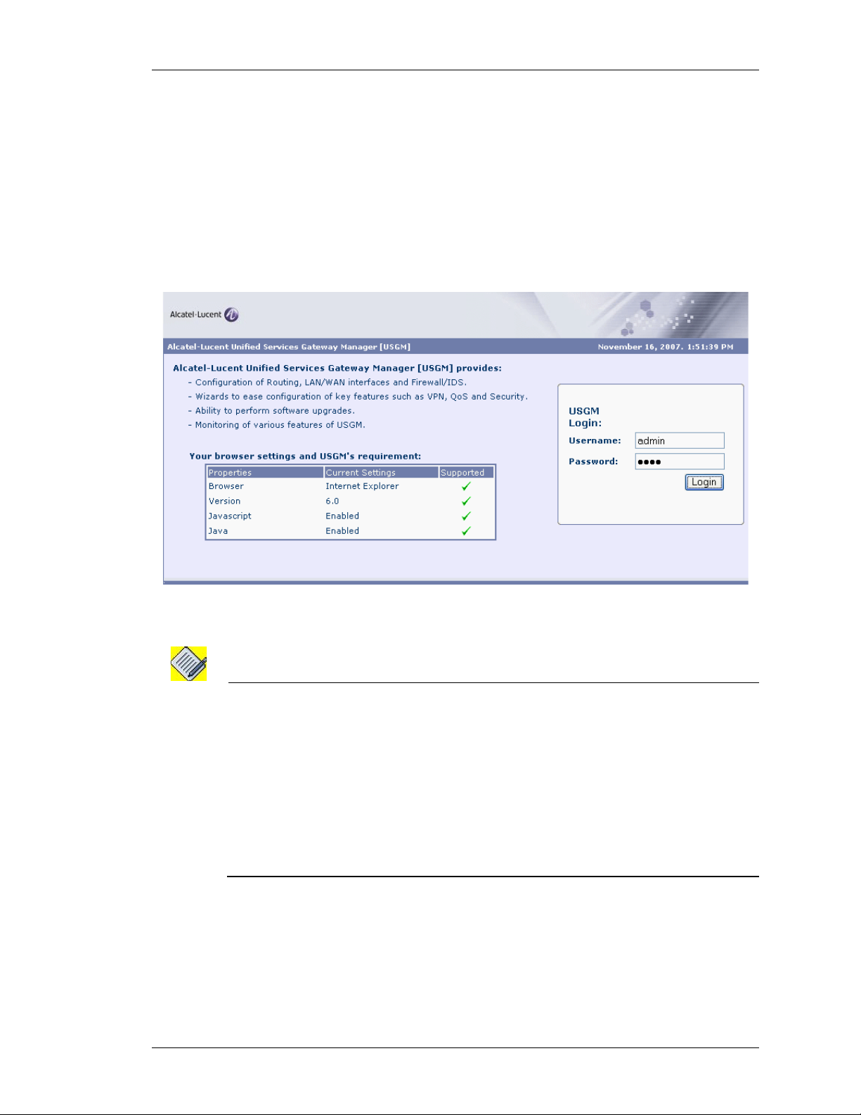
LOGON TO USGM
The web interface is launched with the login page.
Step 1: Enter the user name and the password in the Username and Password
fields.
Use the default ‘superadmin’ user account or use the AAA user name and
password configured using the CLI to login to USGM.
(For more information on configuring AAA user name and password, refer
the note below.)
Except on the first page, right running head:
Heading1 or Heading1NewPage text (automatic)
Launching the GUI
Figure 1: Logon to USGM
Note: To enable AAA services on your system, enter the command aaa services in
configuration mode.
ALU (config)# aaa services
Establish authentication to new users by configuring new user accounts. To configure
new user account, use the following command:
username <user-name> {password [5] <password>|nopassword|
secret [5] <password>}
Example:
ALU (config)# username user1 password pass1
Web GUI User Guide
Beta Beta
Alcatel-Lucent
7
Page 16
Left running head:
Chapter name (automatic)
GUI Layout and Logging on to USGM
Step 2: Click Login.
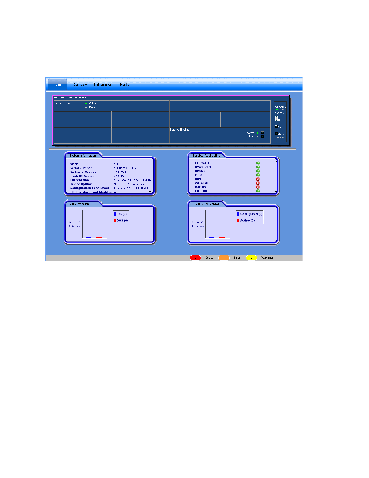
Step 3: On successful login, the USGM main page is displayed.
Figure 2: USGM Home Page
Top Panel
The Top Panel of the USGM home page has the following standard buttons:
Device, Tools, Help and Logout. Device and Tools enable you to perform some
activities. They are described in detail in the later sections of this guide. Help
gives information on ‘About USGM’. It gives the details about the USGM tool like
the version number, model name, and so on.
The Top Panel of the USGM home page also has a menu bar. The menu bar
consists of menu items. Each menu item and their respective sub menu items are
described in the later sections of this guide.
Alcatel-Lucent
8
Web GUI User Guide
Beta Beta
Page 17

Except on the first page, right running head:
Heading1 or Heading1NewPage text (automatic)
Launching the GUI
Center Panel
The Center Panel displays the front panel view of the system chassis (Services
Gateway - OA-780/OA-740) that houses all the hardware components. This
displays all those line cards that are installed in the system. Mouse-over a
particular card name to view additional information like serial number, slot
number.
The center panel also displays four tabs: the System Information, Service
Availability, Security Alerts and IPSec VPN Tunnels.
• System Information panel provides basic information about the OA-700
(Services Gateway - OA-780/OA-740), its hardware and software configuration.
• Service Availability panel displays the list of all the services available on the
system. The green icon indicates that the service is available and is running on
the system. The red icon indicates that the service is not currently available.
• Security Alerts panel displays a graphical representation of the security alerts.
This gives a real time update on the number of DoS and IDS attacks.
• IPSec VPN Tunnels displays a graphical representation of the number of IPSec
tunnels configured on the system, and number of tunnels that are active. This is
updated real time.
The Bottom Panel has the Status bar, which displays the statlog counts for the
top three priority statlog (Critical, Error, and Warning - categorized by the severity
level). This number is updated real time. These logs enable you to take
appropriate action for smooth function in g of the sys te m.
Click on these buttons to view the details of the respective log messages.
Web GUI User Guide
Beta Beta
Alcatel-Lucent
9
Page 18

Left running head:
Chapter name (automatic)
GUI Layout and Logging on to USGM
DESCRIPTION OF STANDARD BUTTONS ON THE GUI
Majority of the screens have consistent look and feel. They have the same
buttons to take certain actions. To avoid repetition of description of the usage of
these buttons and hyperlinks on every screen shot, they are described here. Any
deviation from these standard buttons and links are described in the specific
section.
A
DD
This button is used to enter a new record. If certain fields have default values, it
populates these. The user can enter data for the new record being created.
E
DIT
This button is used to edit a record.
D
ELETE
This button deletes a record.
R
ESET
Resets the values entered in the fields. After updating the entries for an existing
record, if you want go back to the old values (before saving them), you could hit
the reset values button. This button discard s th e up da tes tha t ar e bein g en te re d
and reverts to the latest saved information from the database.
S
AVE
This button saves all the configured data.
Note: * indicates a mandatory field.
10
Alcatel-Lucent
Web GUI User Guide
Beta Beta
Page 19
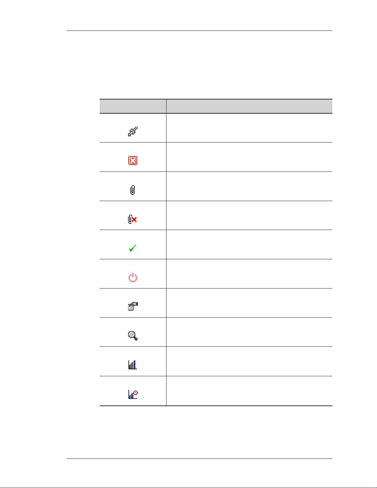
ICONS AND LABELS
The following table lists the icons and labels used in the OA-700 Web GUI tool.
Table 1: Icons, Labels in the OA-700 Web GUI Tool
Icon/Label Description
Except on the first page, right running head:
Heading1 or Heading1NewPage text (automatic)
Launching the GUI
Configure/Edit the selected item.
Delete.
Click this icon to delete the selected item.
Attach.
Click this icon to attach an interface.
Detach.
Click this icon to detach an interface.
Activate.
Click this icon to activate the interface.
Shutdown.
Click this icon to shutdown the interface.
Select.
Click this icon to select an item from the available list.
View.
Click this icon to view details of the selected item.
View Statistics.
Click this icon to view statistics.
Disable Statistics.
Click this icon to disable statistics.
Web GUI User Guide
Beta Beta
Alcatel-Lucent
11
Page 20

Left running head:
Chapter name (automatic)
GUI Layout and Logging on to USGM
Icon/Label Description
LOGOUT
To logout from the USGM, click Logout button on the Top Panel. Confirm at the
prompt to logout.
Enable Statistics.
Click this icon to enable viewing statistics.
Log out.
Note: The system automatically logs you out of the tool if there is no activity for 15 minutes.
When you perform any activity after 15 minutes of inactivity, the system prompts you
to login again.
12
Alcatel-Lucent
Web GUI User Guide
Beta Beta
Page 21

For final production, import color definitions from
For final production, import color definitions from
\\daldoc01\docteam\templates\framemaker\book-template\color-defs\ production-colors.fm.
\\daldoc01\docteam\templates\framemaker\book-template\color-defs\ production-colors.fm.
Do not import other template elements such as page layout.
Do not import other template elements such as page layout.
To return to the draft version, import color def’ns from draft-colors.fm.
To return to the draft version, import color def’ns from draft-colors.fm.
To switch to the beta version, import color def’ns from beta-colors.fm
To switch to the beta version, import color def’ns from beta-colors.fm
CHAPTER 3
CONFIGURE
This chapter provides procedure to configure various features like interfaces,
routing, traffic classification, filters, IPSec policy, and QoS.
Optional footer:
Manual title (to set,
redefine ManualTitle
variable)
Alcatel-Lucent
Web GUI User Guide
Beta Beta
Beta Beta
Pagination:
Numeric &
continuous
with
preceding
13
section of
book
Page 22
Left running head:
Chapter name (automatic)
Configure
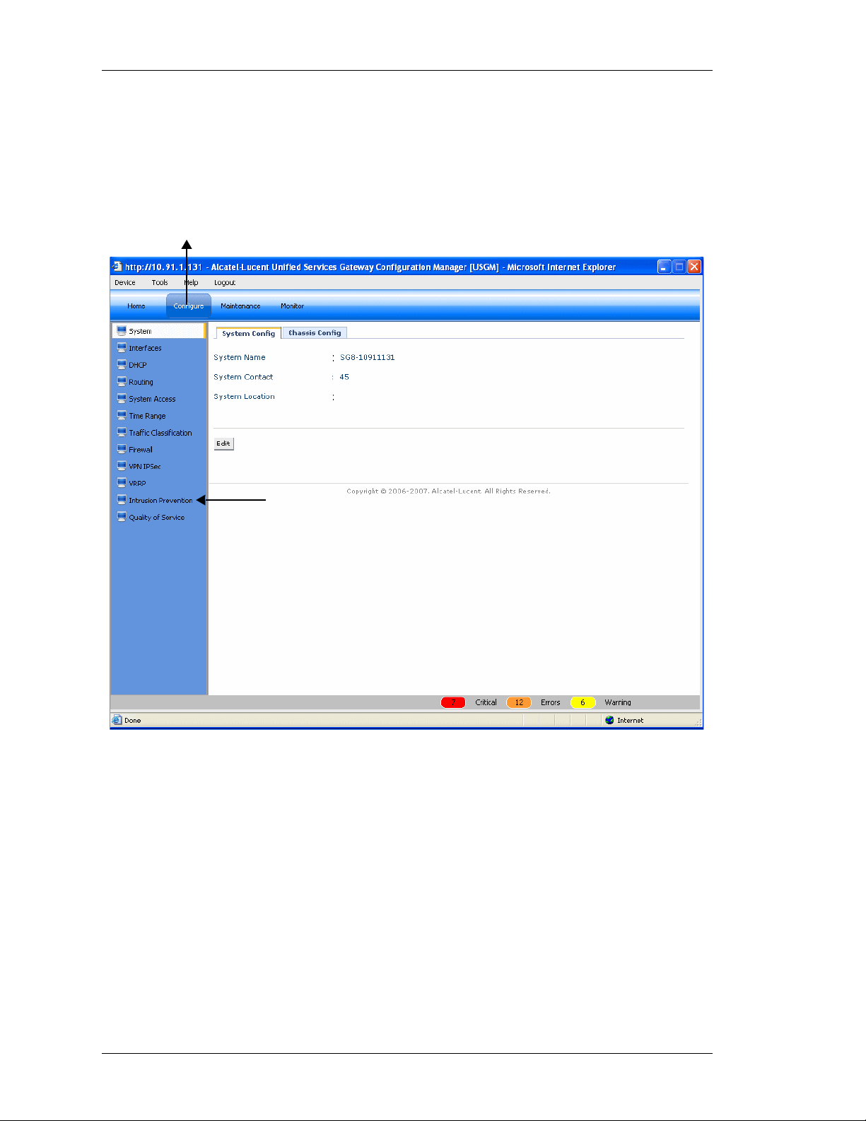
CONFIGURE
From the USGM menu bar, click Configure. All submenu/links under Configure
are displayed in the left navigation panel as shown below, which allows you to
perform configurations for Interfaces, Firewalls, VPNs, Routing, and other tasks.
Menu Bar
Submenu
Figure 3: USGM - Configure Main Page
By default, System is selected and its details are displayed in the Center Panel.
14
Alcatel-Lucent
Web GUI User Guide
Beta Beta
Page 23
SYSTEM
The System sub-menu allows to view and/or edit system parameters, and view
chassis configuration.
S
YSTEM CONFIGURATION
The page allows you to view and/or edit system parameters.
V
IEWING SYSTEM CONFIGURATION
Step 1: From the USGM menu bar, click Configure. All submenu/links under
Configure are displayed in the left navigation panel as shown below.
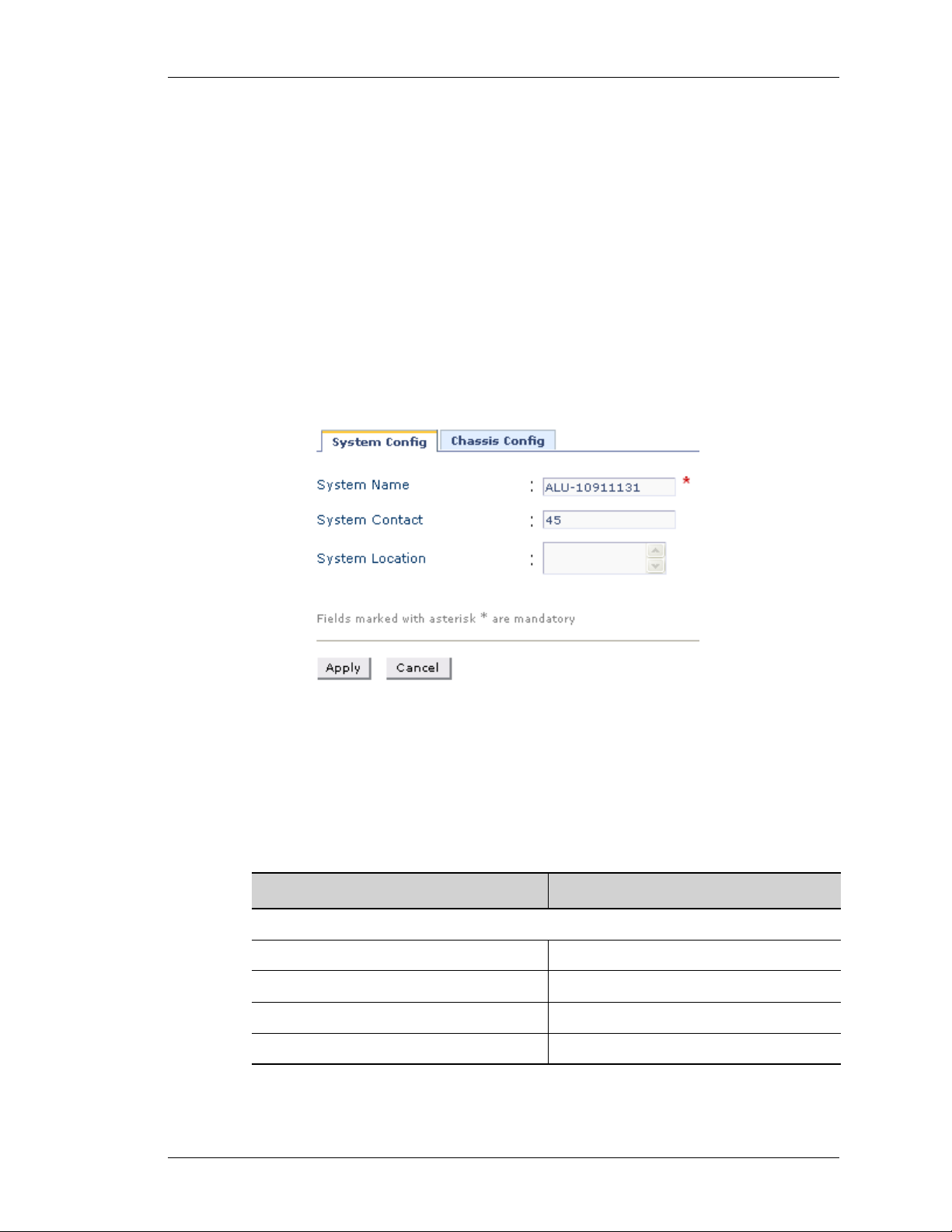
Step 2: By default, System sub-menu is selected. System page has two tabs:
System Config and Chassis Config. By default, System Config page is
displayed in the center panel.
Except on the first page, right running head:
Heading1 or Heading1NewPage text (automatic)
Configure
Figure 4: System Config
The table below provides description of all the fields in the System Config page.
Table 2: System Config Field Description
S
YSTEM CONFIG
System Name Name given to the system.
System Contact Contact details.
System Location Place where the system is located.
Edit Edit system parameters.
Web GUI User Guide
Field Description
Alcatel-Lucent
15
Beta Beta
Page 24
Left running head:
Chapter name (automatic)
Configure
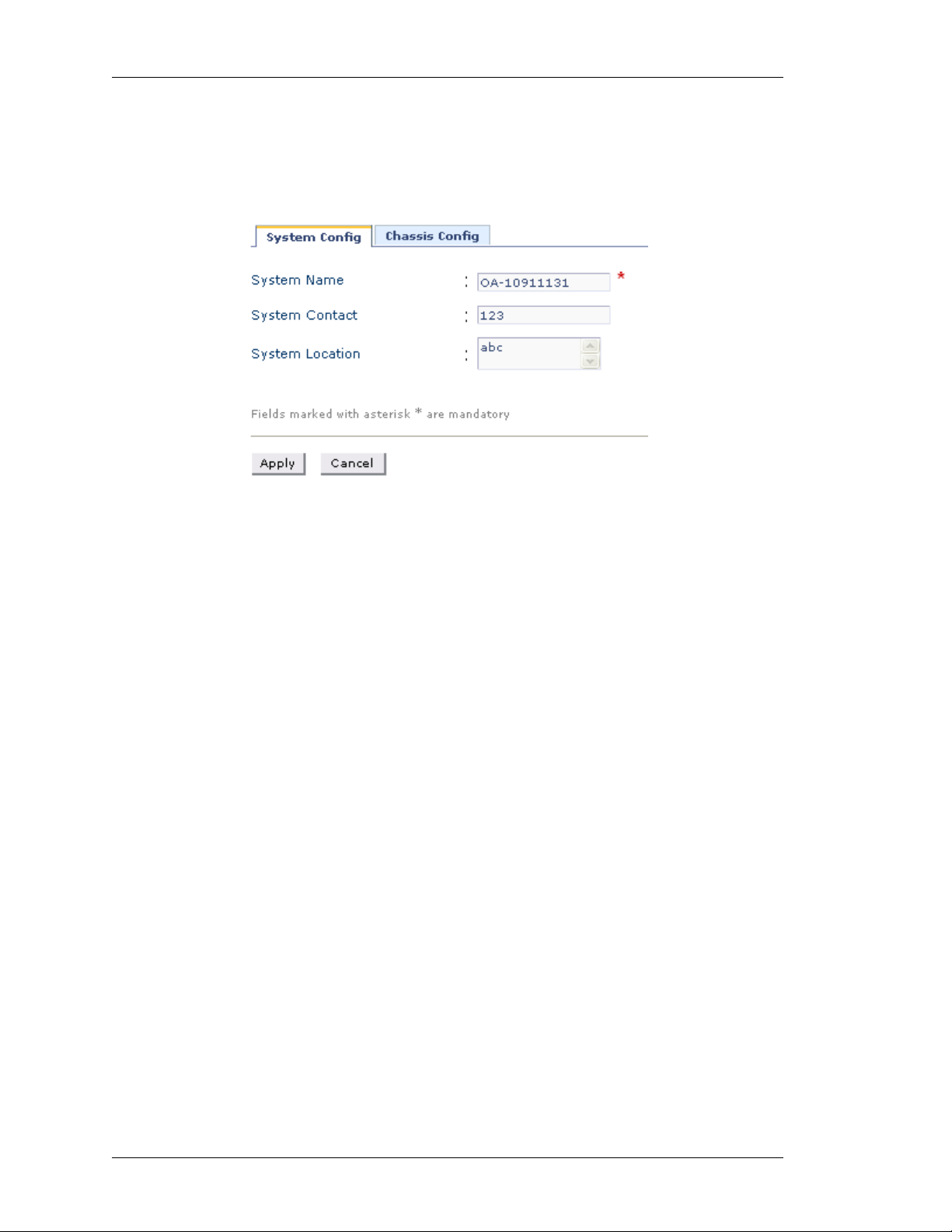
DIT SYSTEM PARAMETERS
E
Step 1: From the System Config page, click Edit to edit the system parameters.
The following page is displayed:
Figure 5: Edit System Configuration
Step 2: Enter or edit the system name, system contact, and system location in the
respective fields. (System Name is mandatory.)
Step 3: Click Apply to save the changes or click Cancel to cancel the operation.
16
Alcatel-Lucent
Web GUI User Guide
Beta Beta
Page 25
CHASSIS CONFIGURATION
This page lists the respective slot numbers and the line cards associated with it
that are installed in the system.
This also displays the details of the OA-700 base system that includes the
following components: OA-700 Chassis, Switch Fabric, Services Engine, Fan
Tray and Power Tray.
V
IEWING CHASSIS CONFIGURATION
Step 1: From the USGM menu bar, click Configure. All submenu/links under
Configure are displayed in the left navigation panel as shown below.
Step 2: By default, System sub-menu is selected.
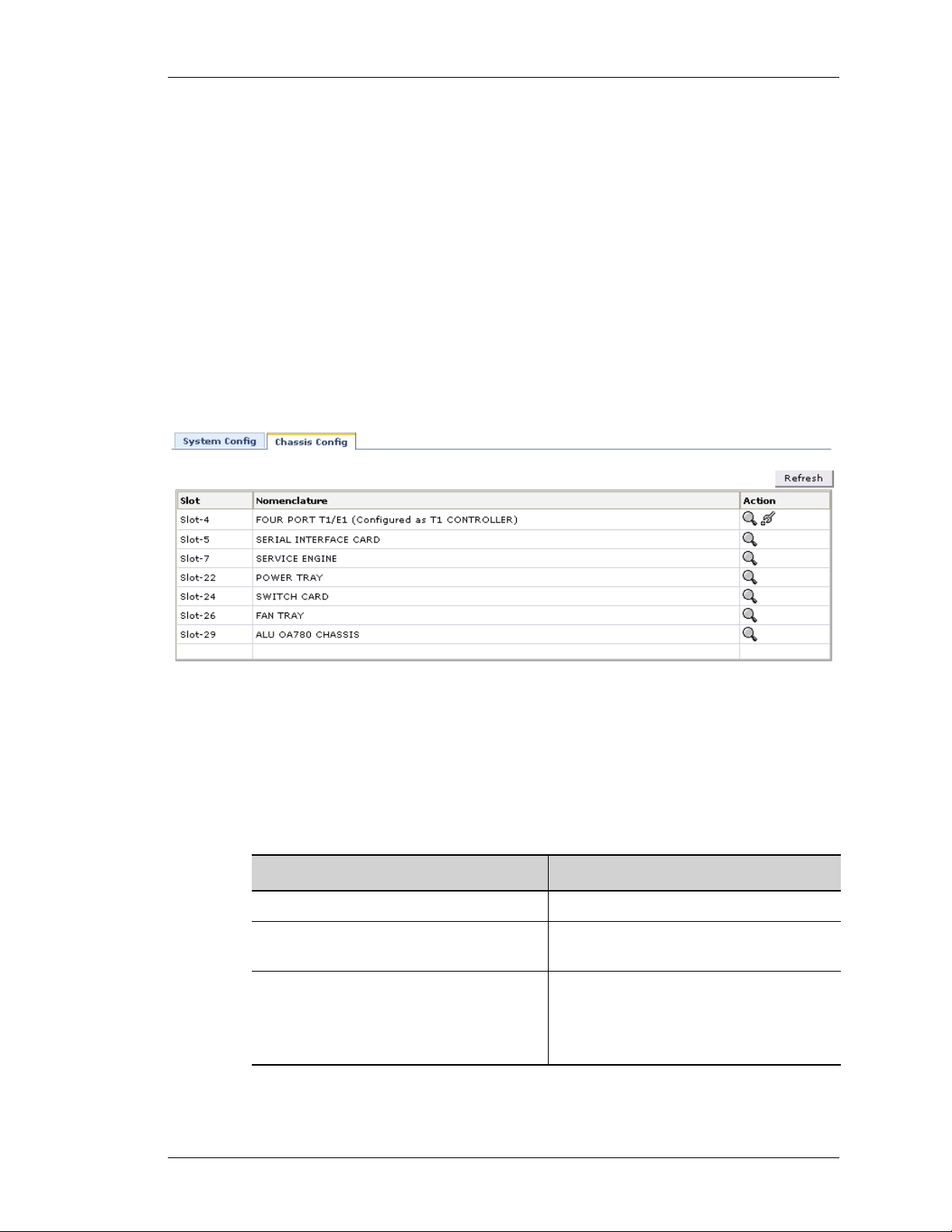
System page has two tabs: System Config and Chassis Config. Click Chassis
Config tab. The following page is displayed in the center panel.
Except on the first page, right running head:
Heading1 or Heading1NewPage text (automatic)
Configure
Figure 6: Chassis Config
The table below provides description of all the fields in the Chassis Config page.
Table 3: System Config Field Description
Slot The slot number of the line card
Nomenclature The name of the line card/system
Action Provides an option to view the details of
Web GUI User Guide
Field Description
component
the respective card.
Note: Provides an option to set the card
type to T1 or E1.
Alcatel-Lucent
17
Beta Beta
Page 26
Left running head:
Chapter name (automatic)
Configure
IEWING CARD DETAILS
V
This enables you to view the details of the respective card.
1. Click View icon in the Action column corresponding to the line card whose details
is to be viewed. The following pop up window is displayed:
Figure 7: Chassis Config - View
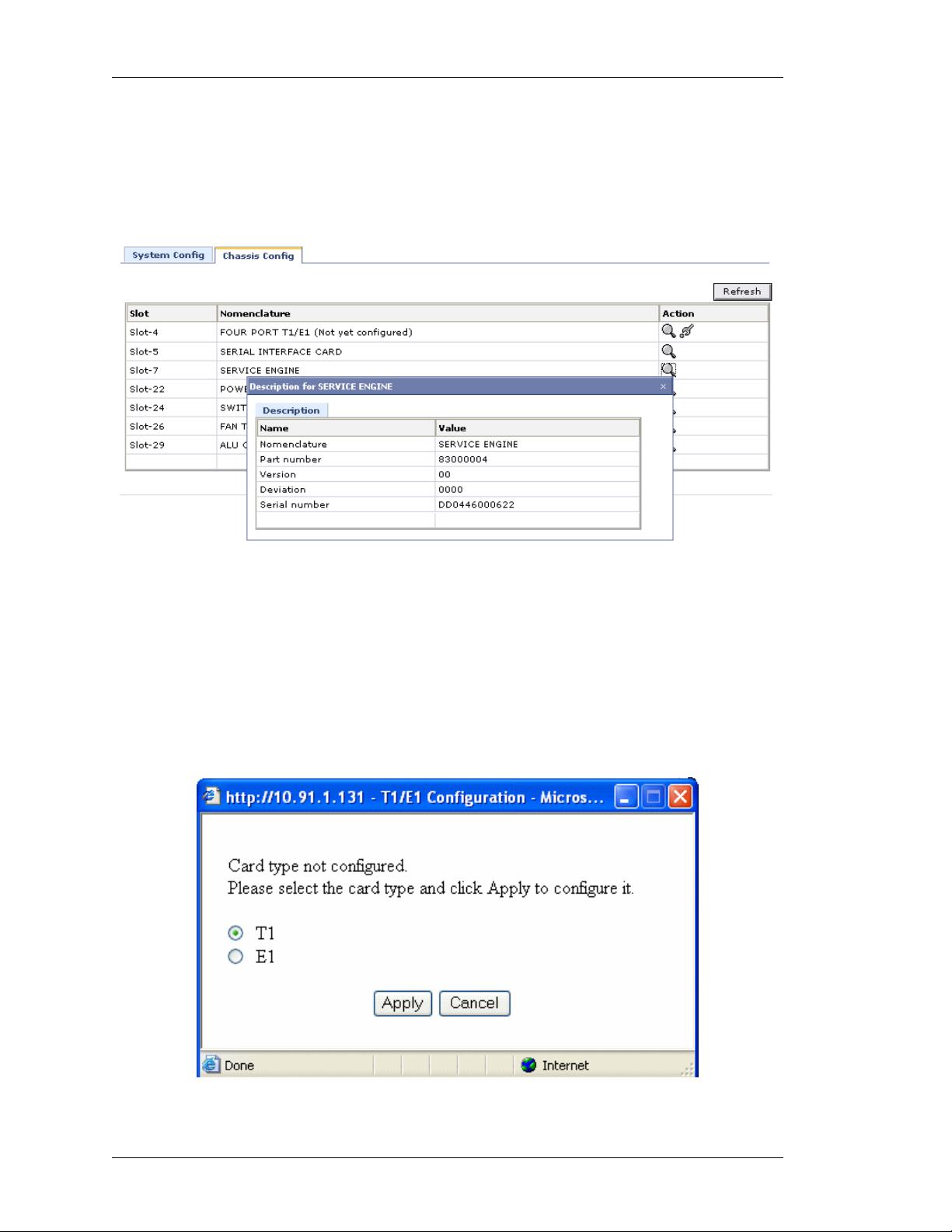
S
ETTING CARD TYPE TO T1 OR E1
This enables you to set the T1/E1 line card type to T1 or E1 for the first time.
1. Click Configure icon in the Action column against the T1E1 line card.
2. The following message box is displayed prompting you to set the line card type to
T1 or E1:
18
Figure 8: Chassis Config - Setting Card Type to T1 or E1
Alcatel-Lucent
Web GUI User Guide
Beta Beta
Page 27
Except on the first page, right running head:
Heading1 or Heading1NewPage text (automatic)
Configure
3. Select the card type and click Apply or click Cancel to cancel the operation.
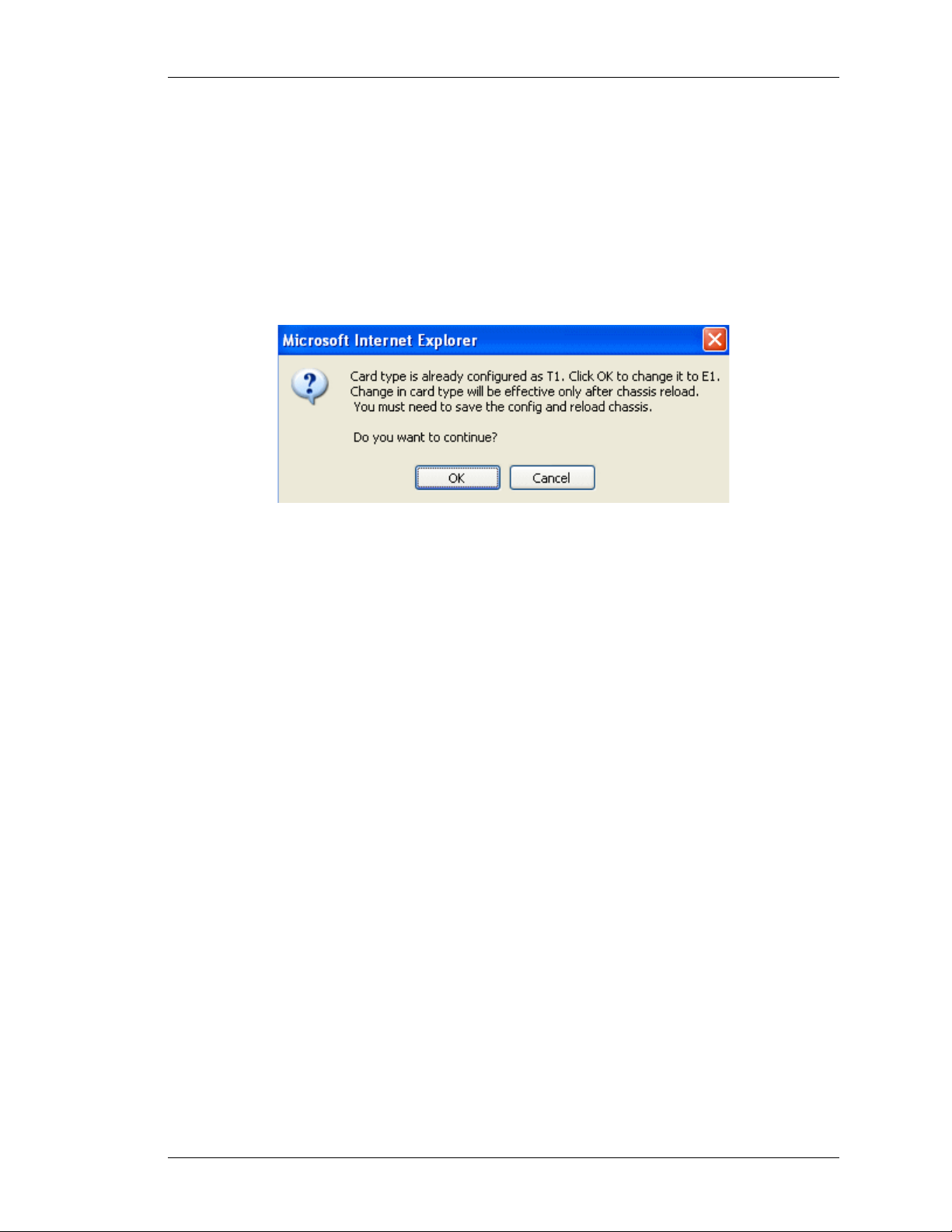
HANGING CARD TYPE
C
This enables you to change the already configured card type to T1 to E1.
1. Click Configure icon in the Action column against the T1E1 line card.
2. The following message box is displayed:
Figure 9: Chassis Config - Changing Card Type
3. Click OK to continue.
Web GUI User Guide
Beta Beta
Alcatel-Lucent
19
Page 28

Left running head:
Chapter name (automatic)
Configure
INTERFACES
The Interfaces page allows you to configure the interfaces supported by OA-700.
The page lists the interfaces based on the line cards installe d on your system. The
list also includes those interfaces that have already been configured through CLI.
This section explains on how to configure the following interfaces:
• Configure Gigabit Ethernet (GigE) Interface
• Configure T1 Controller
• Configure E1 Controller
• Configure Encapsulation on a Channelized Serial Interface
• Configure Serial Interface (V.35/ X.21)
• Configure Logical Interface
i. Virtual LAN (VLAN)
ii. Configure Tunnel Interface
iii. Configure Loopback Interface
Note: The interfaces page displays the MLFR and MLPPP interfaces configured through
CLI. Currently, these interfaces cannot be configured through GUI.
20
Alcatel-Lucent
Web GUI User Guide
Beta Beta
Page 29
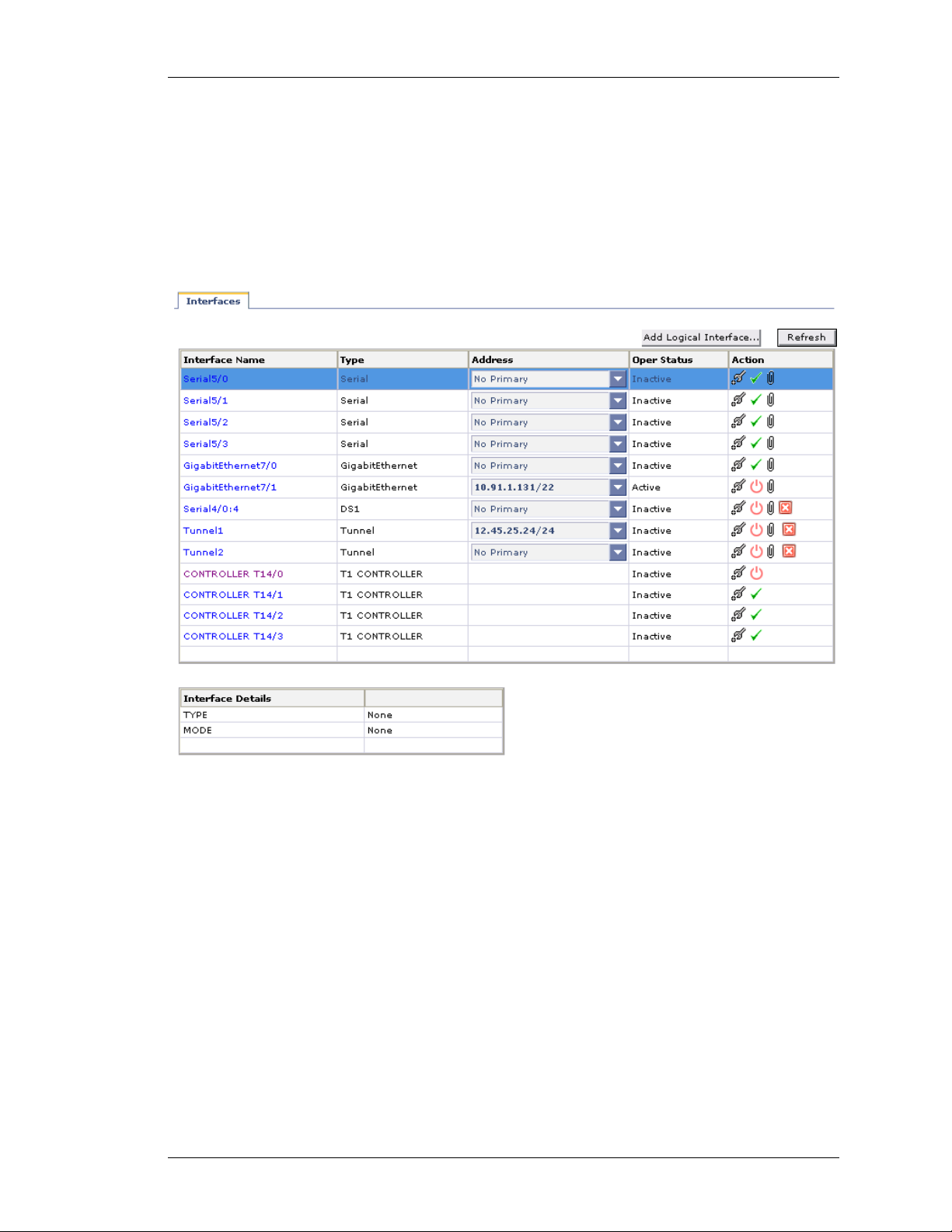
VIEWING INTERFACES
Step 1: From the USGM menu bar, click Configure. All submenu/links under
Configure are displayed in the left navigation panel as shown below.
Step 2: Click Interfaces sub-menu. The Interfaces page is displayed with the list
of all the interfaces available on your system.
The list also displays those interfaces configured using the CLI commands.
Except on the first page, right running head:
Heading1 or Heading1NewPage text (automatic)
Configure
Figure 10: Interfaces
Web GUI User Guide
Beta Beta
Alcatel-Lucent
21
Page 30

Left running head:
Chapter name (automatic)
Configure
The table below provides field description for the Interfaces page.
Table 4: Interface Field Description
I
NTERFACES
Interface Name Name of the interface configured on the
Type Interface type configured such as
Address IP address of the interface
Operational Status Shows if the interface is operationally
Field Description
system.
GigabitEthernet, loopback, serial
interface, etc.
active or inactive.
Action Provides option to edit, activate/
shutdown the interface, and associate
policy/ies to the interface
Refresh Update the interface page
Interface Details This table displays the details of the
selected interface.
22
Alcatel-Lucent
Web GUI User Guide
Beta Beta
Page 31

CONFIGURE GIGABIT ETHERNET (GIGE) INTERFACE
Ethernet is a local area technology, with networks traditionally operating within a
single building, connecting devices in close proximity. At most, Ethernet devices
could have only a few hundred meters of cable between them, making it
impractical to connect geographically dispersed locations. Modern advancements
have increased these distances considerably, allowing Ethernet networks to span
tens of kilometers.
Follow the procedure below to configure Gigabit Ethernet interface through the
Web GUI.
Step 1: On the Interfaces page, click Configure icon against the Gigabit
Ethernet interface that is to be configured.
This displays the Interface Configuration page in the Center Panel. Interface
Configuration page contains basic and advanced details and secondary address
details table.
Except on the first page, right running head:
Heading1 or Heading1NewPage text (automatic)
Configure
Figure 11: Interfaces - Configuring GigE Interface Details
Web GUI User Guide
Beta Beta
Alcatel-Lucent
23
Page 32

Left running head:
Chapter name (automatic)
Configure
Step 2: Configure primary IP address in the Basic table.
1. Enter the IP address and subnet mask for the interface in the IP Address and
Mask field.
2. Enter description for the interface in the Description field.
3. Click Apply to add the details, or Reset to retain the original details.
4. Click Remove to delete the configured IP address.
Step 3: Configure secondary IP address for the interface in the Secondary table.
Click New Secondary Address to add a new secondary address to the selected
interface. Fields to enter the IP address is populated.
1. Enter the secondary IP address and subnet mask for the interface in the IP
Address and Mask column.
2. Click Apply to add the secondary IP address, or click Cancel to cancel adding
secondary IP address.
3. Click Delete icon in the Action column to delete the secondary address.
Step 4: Configure advanced details in the Advanced table. The table displays the
default values. You can retain the same or configure as required.
1. Select the required Duplex operation to be configured on the interface from the
Duplex drop down list: Auto/Full/Half.
Full-duplex refers to the ability of a network, to send and receive data at the
same time.
2. Select the flow control option for the incoming traffic from the Flow-Control
Received drop-down list: On/Off
3. Enter the MTU value (Maximum Transmission Unit) of the interface, i.e., the
maximum packet size that the interface can accept in the MTU field (in the range
64 - 1500).
4. Select the flow control option for the outgoing traffic from the Flow-Control Se nd
drop-down list: On/Off
5. Click Apply to add the set values, or click Reset to retain the original values.
24
Step 5: Click Close at the bottom of the int er fa ce co nf igu ra tio n page to sav e th e
GigE interface configuration.
Alcatel-Lucent
Web GUI User Guide
Beta Beta
Page 33

CONFIGURE T1 CONTROLLER
The interface page allows you to configure the T1 Controller.
Also, this page allows you to configure the Serial Interfaces from the T1 or E1
page.
The T1 and E1 interfaces are two different, independent standardized Time
Division Multiplexing (TDM) technologies. These technologies enable the
transmission of several (multiplexed) voice/data channels simultaneously on the
same transmission facility.
The T1 standard is mostly deployed in Japan and No rth American countries, while
the E1 is prevalent in Europe and most of the Asian countries including India.
The T1 interface provides a transmission rate of 1.544 Mbps. It can support up to
24 user channels, each at a 64 kbps access rate. The T1 interface supports 4
different bit structures, dictated by the mode of operation: Frame, Super Frame,
Extended Super Frame and Unframed.
These bit structures determine how the bits are interpreted. A T1 basic frame is
made up of 24 time slots plus 1 framing bit added to them. Each time slot is
regarded as a channel of 64kbps bandwidth. The frame length is 193 bits (24*8 +
1) A framing bit creates a channel of 8kbps and is used for messages,
synchronization and alarms.
Except on the first page, right running head:
Heading1 or Heading1NewPage text (automatic)
Configure
Follow the procedure below to configure the T1 Controller.
Step 1: On the Interfaces page, click Configure icon against the T1 Controller
that is to be configured. The following page is displayed:
Web GUI User Guide
Beta Beta
Alcatel-Lucent
25
Page 34

Left running head:
Chapter name (automatic)
Configure
26
Figure 12: Interfaces - Configuring T1 Controller
Step 2: Specify the cable length parameters in the Cable Length box. The cabl e
length can be of the type Short or Long.
• Select the Long radio button, and select the pulse value from the Pulse drop-
down list.
Long option configures the transmit and receive levels for a cable length (line
build-out) longer than 660 ft for a T1 trunk. The default length of the cable for
a T1 is Long 0db.
• Select the Short radio button, and select the length from the Length drop-down
list.
Short option sets the transmit attenuation for a cable length (line build-out) of
660 feet or shorter for a T1 trunk.
Alcatel-Lucent
Web GUI User Guide
Beta Beta
Page 35

Except on the first page, right running head:
Heading1 or Heading1NewPage text (automatic)
Configure
Step 3: Select the framing, line code, and clock source from the Framing, Line
Code, and Clock Source drop down lists.
• Framing: Select the framing option: esf/sf to determine which framing type is
required for the T1 circuit.
Framing is configured where the router or access server is intended to
communicate with t1 fractional data lines.
i. esf (Extended Super Frame) - Type of frame format used. Also known as D5
or Fe. Each extended superframe consists of 24 frames.
ii. sf (Super Frame): Type of frame format used. A Superframe is a structure
constructed of 12 Frames, numbered: 1 - 12. It is also called as the D4 frame.
• Line Code: Select the line option: ami/b8zs to set the line code for T1.
Line Code is configured where the router or access server is intended to
communicate with T1 fractional data lines.
i. ami: Alternate Mark Inversion (AMI) line-code type.
AMI is a line encoding technique (line code) for T1s. This three-level
system uses positive, negative, and grounded pulses (e.g. -5V, 0V, 5V) to
represent logical values. A logical 0 is represented with a grounded or
absent pulse, and a logical 1 by pulses of alternating polarity.
ii. b8zs: Binary 8 Zeros Substitution (b8zs) line code type.
b8zs is an encoding method in T1 and E1 transmission that substitutes a
special bit pattern for 8 consecutive zeros in order to maintain ones
density.
• Clock Source: Select the clock source option: Internal/Line to set the clock
source for T1. Clock source is used to transmit clock signals. The default value for
clock source is internal.
i. Internal: The controller synchronizes itself to the internal (system) clock.
ii. Line: The controller recovers external clock from the line and provides the
recovered clock to the internal (system) clock generator.
Web GUI User Guide
Beta Beta
Alcatel-Lucent
27
Page 36

Left running head:
Chapter name (automatic)
Configure
Step 4: Configure channel groups on the controller. This creates a channel-group
that will form a channelized serial interface. Click Configure Channel Group to
configure channel group. Channel Group Configuring pop up window is
displayed.
Figure 13: Interfaces - T1 Controller - Channel Group Configuring
• Enter the channel number in the Channel Number field.
• Enter the range of the time slots that can be associated with the T1 controller in
the Time Slot field.
• Select the speed from the Speed drop down list. Default speed is 64 kbps.
• Click Accept. The channel group thus con figured is d isplayed u nder th e Channel
Group Configuration table. Repeat this procedure to configure more channel
groups.
Step 5: Click Apply to save the T1 Controller configuration or click Close to
cancel the operation.
Step 6: The channel-group thus configured forms the channelized serial
interface, and is displayed in the Interfaces page.
Note: You can configure encapsulation on a channelized serial interface. See “Configure
Encapsulation on a Channelized Serial Interface” for more details on this.
28
Alcatel-Lucent
Web GUI User Guide
Beta Beta
Page 37

CONFIGURE E1 CONTROLLER
The interface page allows you to configure the E1 Controller.
The E1 interface provides a transmission rate of 2.048 Mbps. It can support up to
32 user channels, though usually only 30 channels are used as dedicated user
channels. An E1 basic frame is made up of 256 bits, 32 time slots, each
containing 8 bits. Each time slot provides a 64 kbps data throughput. An E1 line
connects two points in one of which, the information is multiplexed and in the
second demultiplexed.
Follow the procedure below to configure the E1 Controller.
Step 1: On the Interfaces page, click Configure icon against the E1 Controller
that is to be configured. The following page is displayed:
Except on the first page, right running head:
Heading1 or Heading1NewPage text (automatic)
Configure
Figure 14: Interfaces - Configuring E1 Controller
Web GUI User Guide
Beta Beta
Alcatel-Lucent
29
Page 38

Left running head:
Chapter name (automatic)
Configure
Step 2: Select the framing, line code, and clock source, and Line Termination
from the Framing, Line Code, Clock Source, and Line Termination drop down
lists.
• Framing: Select the framing option to determine which framing ty p e is requ ire d
for the E1 circuit.
Framing is configured where the router or access server is intended to
communicate with E1 fractional data lines.
i. crc4: 4-bit cyclic redundancy check, i.e., crc4 frame is the E1 frame type.
ii. no-crc4: No cyclic redundancy check, i.e., crc4 frame is not the E1 frame type.
• Line Code: Select the line option: ami/hdb3 to set the line code for E1.
Line Code is configured where the router or access server is intended to
communicate with E1 fractional data lines.
i. ami: Alternate Mark Inversion (AMI) line-code type.
ii. hdb3: High-density bipolar 3 (hdb3) line-code type.
• Clock Source: Select the clock source option: Internal/Line to set the clock
source for E1. Clock source is used to transmit clock signals.
i. Internal: The controller synchronizes itself to the internal (system) clock.
ii. Line: The controller recovers external clock from the line and provides the
• Line Termination: Select the line termination option: 120 ohm/75 ohm to
configure a line impedance.
Step 3: Configure channel groups on the controller. This creates a channel-group
that will form a channelized serial interface. Click Configure Channel Group to
configure channel group. Channel Group Configuring pop up window is
displayed.
recovered clock to the internal (system) clock generator.
30
Figure 15: Interfaces - E1 Controller - Channel Group Configuring
Alcatel-Lucent
Web GUI User Guide
Beta Beta
Page 39

Except on the first page, right running head:
Heading1 or Heading1NewPage text (automatic)
Configure
• Enter the channel number in the Channel Number field.
• Enter the range of the time slots that can be associated with the E1 controller in
the Time Slot field.
• Select the speed from the Speed drop down list. Default speed is 64 kbps.
• Click Accept. The channel group thus con figured is displayed under th e Channel
Group Configuration table. Repeat this procedure to configure more channel
groups.
Step 4: Click Apply to save the E1 Controller configuration or click Close to
cancel the operation.
Step 5: The channel-group thus configured forms the channelized serial
interface, and is displayed in the Interfaces page.
Note: You can configure encapsulation on a channelized serial interface. See “Configure
Encapsulation on a Channelized Serial Interface” for more details on this.
Web GUI User Guide
Beta Beta
Alcatel-Lucent
31
Page 40

Left running head:
Chapter name (automatic)
Configure
ONFIGURE ENCAPSULATION ON A CHANNELIZED SERIAL INTERFACE
C
This page enables you to set encapsulation on a channelized Serial Interface
formed by the channel group configuration on a T1E1 controller.
Follow the procedure below to configure Serial interface.
Step 1: In the Interfaces page, click Configure icon for the Serial interface
whose parameters are to be configured. This displays the Configuration Serial
page in the Center Panel.
Step 2: You need to set the encapsulation type on the interface by selecting the
required option under Encapsulation: HDLC/PPP/Frame Relay/MLPPP/MLFR.
By default, HDLC radio button is selected.
HDLC E
High-level Data Link Control (HDLC) - Layer 2 of the OSI model is the data link
layer. One of the most common layer 2 protocols is the High-level Data Link
Control (HDLC) protocol. In fact, many other layer 2 protocols are based on
HDLC, particularly its framing structure.
1. By default HDLC radio button is selected. (HDLC is the default encapsulation on
NCAPSULATION
the interface), and the following page displays the HDLC parameters:
32
Figure 16: Interfaces - Configure HDLC Encapsulation on a Channelized
Serial Interface
Alcatel-Lucent
Web GUI User Guide
Beta Beta
Page 41

Except on the first page, right running head:
Heading1 or Heading1NewPage text (automatic)
Configure
2. Enter the description for the serial interface in the Description field.
3. Enter the Maximum Packet size or Maximum T ransmission Unit (MTU) size in the
MTU field.
4. Enter the IP address and the Mask in the IP Address and Mask fields. Click
Remove to delete the IP address and re-enter the new IP address.
5. Configure the HDLC keep alive interval by entering the value in Keep Alive field.
It must be less than the corresponding interval at the switch. Range is 0-32767.
Value of 0 turns off the keep alive feature.
6. Click Apply to save the HDLC configuration or click Cancel to cancel the
operation.
PPP E
NCAPSULATION
The Point-to-Point protocol (PPP) emerged as an encapsulation protocol for
transporting IP traffic over point-to-point links. PPP also est ablished a standard fo r
the assignment and management of IP addresses, asynchronous and
synchronous encapsulation, network protocol multiplexing, link configuration, link
quality testing, error detection and option negotiation for such capabilities as
network layer address and data-compression. PPP supports these functions by
providing an extensible Link Control Protocol (LCP) and a family of Network
Control Protocols (NCP) to negotiate optional configuration parameters and
facilities. PPP supports protocols like IP, IPX and DECnet through the Network
Control Protocols.
1. Set the PPP encapsulation on the interface by selecting PPP radio button under
Encapsulation. The following page is displays the PPP parameters:
Web GUI User Guide
Beta Beta
Alcatel-Lucent
33
Page 42

Left running head:
Chapter name (automatic)
Configure
34
Figure 17: Interfaces - Configure PPP Encapsulation on a Channelized Serial
Interface
2. Enter the description for the serial interface in the Description field.
3. Enter the Maximum Transmission Unit (MTU) size in the MTU field. This should
be between 64 and 1500.
4. Select the IP address option from the IP Address drop down list: Static/
Negotiate IP Address with the Peer
• If Static option is selected, enter the IP address and the Mask in the IP
Address and Mask fields. Click Remove to delete the IP address and re-
enter the new IP address.
• If Negotiate IP Address with the Peer is selected, the IP Address will be
assigned based on the negotiation with the peer. Hence the IP address and
the mask fields are not displayed.
5. Select the Server Peer with IP Address option: Enable/Disable
• If Enable option is selected, enter the IP addre ss in the IP Address field. This
will allow to assign IP address entered to the peer on negotiation if "Negotiate
IP Address with the Peer" is selected on the Peer.
• Disable option disables Server Peer with IP Address.
Alcatel-Lucent
Web GUI User Guide
Beta Beta
Page 43

Except on the first page, right running head:
Heading1 or Heading1NewPage text (automatic)
Configure
6. On some links, it may be desirable to require a peer to authenticate itself before
allowing network-layer protocol packets to be exchanged. To enable this
authentication, PPP supports authentication protocols such as PAP, CHAP, EAP
(CHAP - Challenge Authentication Protocol, PAP - Password Authentication
Protocol, EAP - Extensible Authentication Protocol). Authentication is not
mandatory.
7. Set the authentication protocol for authenticating the peer by selecting the option
from PPP Authentication drop-down list: Chap/Pap/Eap/None
• You can set a user name for PPP authentication on either the server side or
client side. Select the Use below credentials for client/Use below
credentials for server check box to enter the user name and password on
the client side/server side.
i. Enter the user name and the password in the User Name and Password
fields. Confirm password in the Confirm Password field.
• Selecting None option for PPP authentication resets or negates the
authentication protocol.
8. Click Advanced Options to initiate LCP negotiation on a PPP encapsulation and
configure PPP Timers. The following p age is displayed:
Figure 18: Interfaces - Configure PPP Encapsulation on a Channelized Serial
Interface - Advanced Options
Web GUI User Guide
Beta Beta
Alcatel-Lucent
35
Page 44

Left running head:
Chapter name (automatic)
Configure
• Configure LCP parameters in LCP Configuring table. This helps in deciding
whether the system initiates the LCP negotiation or just responds.
i. Enter the maximum echo value in Max Echo field.
ii. Enter the echo interval in Echo Interval field.
• Configure the PPP Timer configuration in Timer Configuring table.
i. Enter the restart timer in Restart Timer field to set the time period for
ii. Enter the maximum number of pings before termina ting to se nd p acke t s in the
iii. Enter the max configure value in Max Configure field.
iv. Enter the max failure value in Max Failure field.
This denotes the maximum number of unanswered LCP echo requests
sent before LCP decides that the peer is down. The value “0” implies that
the link will not be brought down on the basis of unanswered echo
requests. Default echo interval is 5 seconds.
This denotes the interval between the LCP echo requests sent. “ 0” implies
that no echo requests are sent. The default value is 10 seconds.
retransmission of LCP and NCP packets. The default value is 3 seconds.
Max Terminate field.
This terminates request packets (Number of LCP or NCP) without
receiving a Terminate Ack before assuming that the peer is unable to
respond. The default value is 2 seconds.
Configure Request packets (Number of LCP or NCP) without receiving a
valid Configure Ack/NaK/Reject before assuming that the peer is unable
to respond. The default value is 10 seconds.
Configure NaK packets (Number of LCP or NCP) without receiving a
Configure Ack before assuming that configuration is not converging. The
default value is 5 seconds.
• Click OK to save LCP and PPP Timers configuration or click Cancel to cancel the
operation.
9. After configuring the parameters, click Apply to save the PPP configuration or
click Cancel to cancel the operation.
36
Alcatel-Lucent
Web GUI User Guide
Beta Beta
Page 45

Except on the first page, right running head:
Heading1 or Heading1NewPage text (automatic)
Configure
FRAME RELAY ENCAPSULATION
Frame Relay (FR) is a high performance WAN protocol that operates at the
physical and data-link layers of the OSI reference model. This protocol was
originally designed for use across ISDN interfaces but today it is used over a
variety of other network interfaces as well. Frame-relay is a strictly layer 2 protocol
suite which enables it to offer high performance and greater transmission
efficiency. This makes Frame Relay suitable for current WAN applications like
LAN interconnection.
1. Set the Frame Relay encapsulation on the interface by selecting Frame Relay
radio button under Encapsulation. The following page is displays the Frame
Relay parameters:
Figure 19: Interfaces - Configure Frame Relay Encapsulation on a
Channelized Serial Interface
2. Enter the description for the serial interface in the Description field.
3. Enter the Maximum Packet size or Maximum T ransmission Unit (MTU) size in the
4. Enter the IP address and the Mask in the IP Address and Mask fields.
Web GUI User Guide
Beta Beta
MTU field. This should be between 64 and 1500.
Alcatel-Lucent
37
Page 46

Left running head:
Chapter name (automatic)
Configure
5. Enter the DLCI value in the DLCI field.
Data-link Connection Identifiers - Frame Relay virtual circuits are identified by
DLCIs. These values are typically assigned by the Frame Relay service
provider. The DLCIs have a local significance which means that their values
are unique to the link. The system provides support for point-to-point FR
DLCIs only.
6. Configure the LMI (Local Management Interface) parameters in the LMI
Configuration table.
Configure the LMI values manually or click Set Defaults to set the default
values for LMI parameters.
• Select the LMI type from the LMI Type drop down list: Auto Sense/ANSI/
• Enter the LMI Keep Alive interval in the Keep Alive field.
• Enter the polling interval value in the Polling Interval field. The default value
• Enter the DTE error threshold value in Error Threshold field. The default
• Enter the DTE monitored event count in the Monitored Event Count field.
7. FR can also be configured on a sub-interface. And, multiple sub-interfaces with
FR can be configured. For configuring Frame Relay on a sub-in terface on a se rial
interface, follow the steps given below:
• Click Add Sub Interface to configure a sub interface. Create Sub Interface
Q933A.
LMI Auto Sense is activated by default (as the system acts as a DTE).
The LMI Auto Sense will be activated when the physical interface is up
and LMI type is not configured on that interface.
The default value is 10 seconds. The LMI keepalive value should typicall y
be equal to the corresponding interval at the switch.
is 6. This is used to set the full status polling interval on a DTE interface.
value is 3.
The default value is 4.
pop up window is displayed.
38
Figure 20: Interfaces - Configure Frame Relay Encapsulation on a
Channelized Serial Interface - Create Sub Interface
Alcatel-Lucent
Web GUI User Guide
Beta Beta
Page 47

Except on the first page, right running head:
Heading1 or Heading1NewPage text (automatic)
Configure
• Enter the sub interface number in the Interface Name field.
• Enter the IP address and the Mask in the IP Address and Mask fields.
• Enter the DLCI value in the DLCI field.
• Click Accept to save the configuration or click Cancel to cancel the
operation.
• Click Accept. The sub interface thus configured is displayed under th e Add New
Sub Interface & DLCI Configuration table. Repeat this procedure to configure
more sub interfaces.
8. After configuring the parameters, click Apply to save the Frame Relay
configuration or click Cancel to cancel the operation.
9. The sub interfaces thus configured is displayed in the Interfaces page.
MLPPP E
To establish communication over a PPP Multilink, an MRRU (Maximum Receive
Reconstructed Unit) configuration option is sent to the peer during LCP
negotiation. Optionally, an Endpoint Discriminator Option or SSHNF Option may
also be sent out. LCP negotiation and optional link authentication take place on
each bundle link. IPCP negotiation happens over the bundle, meaning IPCP
packets may be sent on any one of the bundle links. Cert ain LCP packet s like LCP
Echo-Request and LCP Echo-Reply may be transmitted over the bundle. IP
packets are sent over the bundle.
The MLPPP packet is encapsulated using an MLPPP header which is different
from the standard PPP header. It contains a sequence number and additionally
allows for fragmentation or re-assembly of the packet. MLPPP is also referred to
as MP or MPPP.
Note: To configure MLPPP encapsulation on an interface, first a bundle interface
needs to be configured and then MLPPP encapsulation is set on the member
interfaces, to link them to the bundle.
Currently, you can configure the bundle interface only through CLI. The
Interface page lists the MLPPP bundle interfaces created via CLI. Each MLPPP
interface is identified by a bundle ID.
NCAPSULATION
1. Set the MLPPP encapsulation on the interface by selecting MLPPP radio button
Web GUI User Guide
Beta Beta
under Encapsulation. The following page is displays the MLPPP parameters:
Alcatel-Lucent
39
Page 48

Left running head:
Chapter name (automatic)
Configure
40
Figure 21: Interfaces - Configure MLPPP Encapsulation on a Channelized
Serial Interface
2. Each MLPPP interface is identified by a bundle ID. The interfa ce be co m es a
member link of the bundle interface identified by the bundle ID. Select the bundle
identifier from the Bundle Identifier drop-down list.
3. Enter the bundle identification (BID) name to the bundle interface in the
Description field.
4. Enter the Maximum Packet size or Maximum Transmission Unit (MTU) size in the
MTU field. The default MTU on an MLPPP bundle interface is 1494.
5. On some links, it may be desirable to require a peer to authenticate itself before
allowing network-layer protocol packets to be exchanged. To enable this
authentication, PPP supports authentication protocols such as PAP, CHAP, EAP
(CHAP - Challenge Authentication Protocol, PAP - Password Authentication
Protocol, EAP - Extensible Authentication Protocol). Authentication is not
mandatory.
6. Set the authentication protocol for authenticating the peer by selecting the option
from PPP Authentication drop down list: Chap/Pap/Eap/None
Alcatel-Lucent
Web GUI User Guide
Beta Beta
Page 49

Except on the first page, right running head:
Heading1 or Heading1NewPage text (automatic)
Configure
• You can set a user name for PPP authentication on either the server side or
client side. Select the Use below credentials for client/Use below
credentials for server check box to enter the user name and password on
the client side/server side.
i. Enter the user name and the password in the User Name and Password
fields. Confirm password in the Confirm Password field.
• Selecting None resets or negates the authentication protocol.
7. Click Advanced Options to initiate LCP negotiation on a PPP encapsulation and
configure PPP Timers. The following p age is displayed:
Figure 22: Interfaces - Configure MLPPP Encapsulation on a Channelized
Serial Interface - Advanced Options
• Configure LCP parameters in LCP Configuring table. This helps in deciding
Web GUI User Guide
Beta Beta
whether the system initiates the LCP negotiation or just responds.
i. Enter the maximum echo value in Max Echo field.
This denotes the maximum number of unanswered LCP echo request s
sent before LCP decides that the peer is down. The value “0” implies that
the link will not be brought down on the basis of unanswered echo
requests. Default echo interval is 5 seconds.
ii. Enter the echo interval in Echo Interval field.
This denotes the interval between the LCP echo requests sent. “0” implies
that no echo requests are sent. The default value is 10 seconds.
Alcatel-Lucent
41
Page 50

Left running head:
Chapter name (automatic)
Configure
• Configure the PPP Timer configuration in Timer Configuring table.
i. Enter the restart timer in Restart Timer field to set the time period for
ii. Enter the maximum number of pings before termina ting to se nd p acke t s in the
iii. Enter the max configure value in Max Configure field.
iv. Enter the max failure value in Max Failure field.
• Click OK to save LCP and PPP Timers configuration or click Cancel to cancel the
operation.
8. After configuring the parameters, click Apply to save the MLPPP configuration or
click Cancel to cancel the operation.
retransmission of LCP and NCP packets. The default value is 3 seconds.
Max Terminate field.
This terminates request packets (Number of LCP or NCP) without
receiving a Terminate Ack before assuming that the peer is unable to
respond. The default value is 2 seconds.
Configure Request packets (Number of LCP or NCP) without receiving a
valid Configure Ack/NaK/Reject before assuming that the peer is unable
to respond. The default value is 10 seconds.
Configure NaK packets (Number of LCP or NCP) without receiving a
Configure Ack before assuming that configuration is not converging. The
default value is 5 seconds.
MLFR E
MLFR is defined in FRF 16.1. It is an extension to the Frame Relay Protocol.
The MLFR packet is encapsulated using an MLFR header, which is different from
the standard Frame Relay header . It contains a sequence nu mber and also allows
for fragmentation/reassembly of the MLFR packet. MLFR is also referred to as
MFR.
Note: To configur e MLFR encapsulation on an interface, first a bundle inte rface needs
to be configured and then MLFR encap sulation is set on the member interf aces,
to link them to the bundle.
Currently, you can configure the bundle interface only through CLI. The
Interface page lists the MLFR bundle interfaces created via CLI. Each MLFR
interface is identified by a bundle ID.
1. Set the MLFR encapsulation on the interface by selecting MLFR radio button
NCAPSULATION
under Encapsulation. The following page is displays the MLFR parameters:
42
Alcatel-Lucent
Web GUI User Guide
Beta Beta
Page 51

Except on the first page, right running head:
Heading1 or Heading1NewPage text (automatic)
Configure
Figure 23: Interfaces - Configure MLFR Encapsulation on a Channelized
Serial Interface
2. Each MLFR interface is identified by a bundle ID. The interface becomes a
member link of the bundle interface identified by the bundle ID. Select the bundle
identifier from the Bundle Identifier drop-down list.
3. Enter the bundle identification (BID) name to the bundle interface in the
Description field.
4. Enter the Maximum Packet size or Maximum T ransmission Unit (MTU) size in the
MTU field. The default MTU on an MLPPP bundle interface is 1494.
5. Enter the Link Identification name to the interface that is part of the bundle in the
LID field. The LID can be a maximum of 255 characters.
6. Enter the hello-interval in the Hello-interval field. Hello interval is the duration in
seconds between successive hello messages sent.
7. Enter the ack-interval in the Ack-interval field. Acknowledge interval is the
duration (in seconds) that the bundle link waits for a hello message from its peer,
or the duration it waits before resending the hello message.
8. Enter the retry-count in the Retry-count field. Retry count is the number of times
the bundle link will send out a hello message before any acknowledgment is
received from its peer.
9. After configuring the parameters, click Apply to save the MLFR configuration or
click Cancel to cancel the operation.
Web GUI User Guide
Beta Beta
Alcatel-Lucent
43
Page 52

Left running head:
Chapter name (automatic)
Configure
ONFIGURE SERIAL INTERFACE (V.35/ X.21)
C
This page enables you to configure the parameters for a Serial Interface (V.35/
X.21).
Follow the procedure below to configure Serial interface.
Step 1: In the Interfaces page, click Configure icon for the Serial interface
whose parameters are to be configured. This displays the Configuration Serial
page in the Center Panel.
44
Figure 24: Interfaces - Configuring Serial Interface (V.35/X.21)
Step 2: Configure V .35/X.21 DTE (Data Terminal Equipment) and DCE (Data
Circuit-Terminating Equipment) specific parameters under the Physical
Description box.
• Select the Enable Loopback check box to configure the interface in the loopback
mode.
Loopback is used for troubleshooting and diagnostic purpose. When an
interface is configured in loopback mode, Tx data and Tx clock loop to internal
controller as Rx data and Rx clock. In the same way, Rx data and Rx clock on
line loop out on line as Tx data and Tx clock.
Alcatel-Lucent
Web GUI User Guide
Beta Beta
Page 53

Except on the first page, right running head:
Heading1 or Heading1NewPage text (automatic)
Configure
• Select the TXC Clock Inversion check box to invert the transmit clock to correct
phase shift between the clock and the data.
When DTE/DCE is using external clock source, long cables at high speed
might introduce phase shift in transmitted data and clock. clock inversion can
reduce errors by correcting the phase shift. By default, the transmit clock is
not inverted.
• Enter the CRC in the Cyclic Redundancy Check field.
• Select the clock rate from the Clock Rate drop-down list. Clock rate configures the
speed of the clock.
Step 3: Set the encapsulation for the interface.
Note: You can set the encapsulation type on a Serial interface (V. 35/X.21) by select ing
the required option under Encapsulation: HDLC/PPP/Frame Relay/MLPPP/
MLFR. By default, HDLC encapsulation is selected.
The steps to configure encapsulation on the interface is already covered in the
previous section. The same step s hold g ood for conf iguring enca p sulatio n on a
serial interface. For more details on encapsulation configuration, refer to
“Configure Encapsulation on a Channelized Serial Interface” section.
Step 4: After configuring the parameters, click Apply to save the Serial interface
configuration or click Cancel to cancel the operation.
Web GUI User Guide
Beta Beta
Alcatel-Lucent
45
Page 54

Left running head:
Chapter name (automatic)
Configure
ONFIGURE LOGICAL INTERFACE
C
Follow the procedure below to configure logical interfaces. You can configure
Virtual LAN, GRE Tunnel, and Loopback interfaces.
Step 1: Click Add Logical Interface on the Interfaces page. A drop-down list
lists the logical interfaces that can be configured: Virtual LAN/GRE Tunnel/
Loopback. Choose the required option.
V
IRTUAL LAN (VLAN)
You can configure VLAN on L2GE Switch ports. L2GE card has 8 Switch Ports
and VLAN on L2 ports can be configured for three modes of operatio n.
• Access - This is the default mode. Used to connect end st ations (LAN devices) to
switch ports. Each access port can belong to only 1 VLAN. This port can send and
receive untagged packets.
• Trunk - A trunk port sends and receives only tagged packet s. It interconnect s one
OA-700 (as a switch) to another OA-700 (as a router). VLAN information is
exchanged between them.
• Hybrid - Used to connect to both VLAN-aware (tagged) devices as well as VLAN
unaware (untagged) devices.
Some points to note:
• By default, all the L2 Switch Ports are in Access mode and they are a part of
VLAN 1 (already configured in the device).
• If a VLAN is configured on a particular L2 card, it cannot be con figured on ano ther
card.
• VLAN can be configured for a L2 card and not across L2 cards (i.e, if your device
has more than one L2 card). For routing across VLANs or between traffic on the
L2 card, IRB (Integrated Routing and Bridging) is to be used. This enable s L2 port
capable of taking part in both bridging and routing at the same time.
IRB allows multiple router interfaces to be in a common VLAN, with routing
across such VLAN's.
• A given VLAN interface for IRB can be used only on the 8 ports of the same L2-
GE card.
• If IRB is not enabled for a VLAN interface, policies cannot be configured.
• When no VLANs are configured on the L2 ports, all ports of the switch belong to
one broadcast domain. All the L2 ports participate in pure bridging.
46
Alcatel-Lucent
Web GUI User Guide
Beta Beta
Page 55

Except on the first page, right running head:
Heading1 or Heading1NewPage text (automatic)
Configure
You can also configure Per VLAN STP for the VLAN.
Spanning-Tree Protocol (STP) is a link management protocol that provides path
redundancy while preventing undesirable loops in the network. For an Ethernet
network to function properly, only one active path can exist between two stations.
Multiple active paths between stations cause loo ps in the network. If a loop exists
in the network topology, the potential exists for duplication of messages. When
loops occur, some switches see stations appear on both sides of the switch. This
condition confuses the forwarding algorithm and allows duplicate frames to be
forwarded.
To provide path redundancy, Spanning-Tree Protocol defines a tree that spans all
switches in an extended network. Spanning-Tree Protocol forces certain
redundant data paths into a standby (blocked) state. If one network segment in
the Spanning-Tree Protocol becomes unreachable, or if Spanning-Tree Protocol
costs change, the spanning-tree algorithm reconfigures the spanning-tree
topology and reestablishes the link by activating the standby path. Sp anning-Tree
Protocol operation is transparent to end st ations, which are unaware whether they
are connected to a single LAN segment or a switched LAN of multiple segments.
Follow the following procedure to configure VLAN, enable IRB, and configu re Per
VLAN STP.
Step 1: Click Add Logical Interface on the Interfaces page. A drop-down list
lists the logical interfaces that can be configured. Select Virtual LAN from the list.
Configure VLAN page is displayed as shown below.
Figure 25: Interfaces - Configure VLAN
Web GUI User Guide
Beta Beta
Alcatel-Lucent
47
Page 56

Left running head:
Chapter name (automatic)
Configure
Step 2: Enter the VLAN ID in the VLAN ID field.
Step 3: Check the IRB Enabled check box to configure IRB. The IP Address and
Mask field appears when this check box is selected.
IRB (Integrated Routing and Bridging) allows you to route a given protocol
between routed interfaces and bridge groups within a single switch router.
• Enter the IP address and the Mask in the IP Address and Mask fields.
Step 4: Click Add Port to add the Switch Port/s to the VLAN. Switch Port
Configuring pop up window is displayed.
Figure 26: Interfaces - Configure VLAN - Switch Port Configuring
• Select the Switch Port from the Switch Port drop down list.
• Select the mode from the Mode drop down list: Access/Trunk/Hybrid. This
command is used configure the L2 interface in the access, trunk or hybrid mode.
• Click Accept. The configured switch port is displayed in the Switch Port table.
Repeat this procedure to add more ports.
Note: Maximum of 8 switch ports can be added to a VLAN. Switch ports with only trunk
mode can be added to multiple VLANs.
Step 5: Click Apply to configure the VLAN or click Cancel to cancel the
operation. VLAN is updated and a prompt to configure STP is displayed.
Alcatel-Lucent
48
Web GUI User Guide
Beta Beta
Page 57

Except on the first page, right running head:
Heading1 or Heading1NewPage text (automatic)
Configure
Step 6: Click OK to continue STP configuration. STP Config page is displayed
with the default values in the respective fields.
Figure 27: Interfaces - Configure VLAN - STP Config
Step 7: The VLAN ID for the selected VLAN is displayed in the VLAN ID field.
This is not editable.
Step 8: Enable/Disable the STP Flag by selecting Enable/Disable option from
the STP Enable Flag drop down list.
• Enable enables Spanning Tree parameters - Forward Time, Max Age, Hello Time
• Selecting Disable option disables the Forward Time, Max Age, Hello Time and
Web GUI User Guide
and Priority fields. Enter the values in the respective fields. An option to edit the
STP parameters is also enabled.
i. Forward Time - Enter the forward time in the range 4 - 30 seconds. Defaul t is
15 seconds.
ii. Max Age - Enter the max age value in the range 6 - 40 second s. Defau lt is 2 0
seconds.
iii. Hello Time - Enter the value in the range 1- 10 seconds. Default is 2 seconds.
iv. Priority - Enter the bridge priority in the range 0 - 65535. Default is 32768.
Priority fields. Also, the option to edit the STP parameters is disabled.
Alcatel-Lucent
49
Beta Beta
Page 58

Left running head:
Chapter name (automatic)
Configure
Step 9: Configure the Switch Port parameters. These are configured on per port
basis.
• Click Edit link under Action column against the Switch Port whose state, priority,
and cost parameters are to be configured.
• Configure the required value in the respective fields.
i. Select the state from the State drop down list: Enable/Disable
ii. Enter the path cost in the Cost field (range 1- 65535). The default value is 4.
Note: When two bridges compete for position as the root bridge, configure the PVST cost to
prioritize an interface.
iii. Enter the port priority in the Priority field (range 0 - 255). This priority value is
used to prioritize an interface when two bridges compete for position as the
root bridge. Default value for port-priority is 128.
iv . Click OK to configure the Switch Port parameters or click Cancel to cancel the
operation.
Step 10: Click Apply to save the VLAN STP configuration or click Cancel to
cancel the operation.
Step 11: The VLAN interface thus configured is displayed in the Interfaces
page.
50
Alcatel-Lucent
Web GUI User Guide
Beta Beta
Page 59

Except on the first page, right running head:
Heading1 or Heading1NewPage text (automatic)
Configure
EDIT VLAN CONFIGURATION
Follow the procedure given below to edit the VLAN configuration:
1. In the Interfaces page, click Edit All icon against the VLAN that needs to be
edited. Configure VLAN page is displayed.
Figure 28: Interfaces - Edit VLAN Configuration
2. VLAN Id is not editable.
3. If the IRB is enabled, the IP Address and Mask field displays the configured IP
4. You can configure the secondary IP address for the VLAN interface in the
Web GUI User Guide
Beta Beta
address and mask. Modify if necessary.
Secondary Address table.
Click New Secondary Address to add a new secondary address to the
selected interface. Fields to enter the IP address is populated.
• Enter the secondary IP address and subnet mask for the interface in the IP
Address and Mask column.
• Click Apply to add the secondary IP address, or click Cancel to cancel
adding secondary IP address.
• Click Delete icon in the Action column to delete the secondary address.
Alcatel-Lucent
51
Page 60

Left running head:
Chapter name (automatic)
Configure
5. The Switch Ports table displays the switch ports configured for the VLAN
interface. You can edit/delete the switch ports configured.
Edit Switch Port
•In Edit icon against the switch port that needs to be edited. Switch Port
• Edit the Mode for the switch port. Click Accept or click Cancel to cancel the
Delete Switch Port
• Click Delete icon against the switch port to be deleted.
• The switch port gets deleted.
6. Click Add Port to add new switch ports.
7. After making the necessary changes, click Apply to save the changes or click
Cancel to cancel the operation.
EDIT STP CONFIGURATION
STP for a VLAN can be configured by selecting a particular VLAN in the Interfaces
page.
1. In the Interfaces page, click Edit STP icon for the VLAN interface whose STP
parameters is to be configured. STP Config page is displayed.
2. The VLAN ID for the selected VLAN is displayed in the VLAN ID field. This is not
editable.
3. Make the necessary changes and click Apply to save the changes or click
Cancel to cancel the operation.
Configuring pop up window is displayed.
operation.
DELETE VLAN INTERFACE
1. In the Interfaces page, click Delete icon in the Action column against the VLAN
to be deleted.
2. Confirm at the prompt to delete the VLAN.
52
Alcatel-Lucent
Web GUI User Guide
Beta Beta
Page 61

Except on the first page, right running head:
Heading1 or Heading1NewPage text (automatic)
CONFIGURE TUNNEL INTERFACE
You can configure IPsec tunnel interface or GRE tunnel interface from the
interfaces page.
• Generic Routing Encapsulation Tunnel Interface
Generic Routing Encapsulation is a simple, stateless protocol that allows fo r
the tunneling of any in GRE. IP is used as transport for GRE. GRE tunnels
can be used to form VPNs, connecting remote sites using private IP
addresses via a public network. Typically, GRE tunnel is run between the
customer edge routers and are transparent to the rest of the network.
With GRE tunnels, a provider does not need to convert any core devices to
MPLS or establish MP-BGP sessions. There is also no need to esta blish BGP
route reflectors or modify existing routing configuration or policies. Therefore,
a provider may offer an alternative VPN solution to MPLS in a much shorter
time frame with greatly simplified provisioning and support. GRE tunnels are
used to carry non-IP traffic (like IPX, Appletalk, DECnet from legacy networks)
over an IP backbone.
Configure
GRE tunnel setup and mapping
A GRE tunnel is configured by specifying two endpoints, one local and the
other remote. In order to establish a bidirection al path, a GRE tunnel must be
configured from the remote endpoint as well. No intermediary routers nee d to
be configured, and the tunnel rides on top of standard IP. The only
requirement is that the tunnel must be configured in a context where the
remote endpoint is reachable.
If the remote address of a GRE tunnel is not reachable, then any circuit
associated with that tunnel is brought down. Any interface bound to a GRE
circuit is also marked in a down state, and any route to the tunnel interface is
withdrawn. This prevents the “blackholing” of traffic caused by network
instability, where traffic is sent through a tunnel that can no longer reach the
remote endpoint.
Public addresses must be used for tunnel endpoint addresses. It is possible to
use private IP addresses as the GRE tunnel interface IP address allowing a
private address VPN to be carried over a public network.
GRE Tunnel Features
In addition to the above concepts, some important features should be
highlighted:
• Topology and scalability features
Web GUI User Guide
Beta Beta
Because of the flexible nature of GRE, tunnels can be established in
different topologies.
This use of different topologies also allows GRE tunnels to be scaled
appropriately. Specifically, a hierarchical structure allows a core to be
constructed by connecting core routers together with GRE tunnels. From
that core, additional tunnels can be provisioned to the provider edge
routers.
• Separation of Customer and Provider Routing
Alcatel-Lucent
53
Page 62

Left running head:
Chapter name (automatic)
Configure
• ACLs on GRE tunnels
In OA-700, OSPF protocol instances operate upon their own instance of
the routing table. Routes from one routing table instance are not visible to
the other routing table instance unless it is explicitly redistributed.
Therefore, even though customer routes are present in our routing table,
they will not be picked up by the provider OSPF instance.
Therefore, it is possible for us to have independent OSPF routing
instances for the VPN going over the tunnel and the connection to the
provider network.
In terms of BGP, it is possible to run BGP over the VPN by specifying a
peer IP address that is reachable over the tunnel. This will guarantee that
all the BGP messages to the peer will go over the tunnel.
Access Control Lists (ACLs) are packet filters which determine whether
packets are forwarded or dropped. They are useful for security or policy
purposes. The header in each packet is examined and the relevant
criteria include source and destination address, source and destination
port, or other information. ACLs can be applied to GRE tunnel interfaces,
which means that packet filtering with its corresponding benefits can be
offered for GRE tunnels.
Summary
GRE tunnels are a flexible and powerful tool on any Router for of fering a VPN
service without the need to migrate to an MPLS core network. Contexts and
interfaces are used in combination with GRE tunneling to create a VPN
service complete with private addressing, routing, user authentication, and
debugging and logging.
• GRE tunnels may also be used by providers who wish to offer a VPN service
before transitioning to MPLS.
• GRE protocol is defined in RFC-2784
• Provides a means of encapsulating IP and non IP p ackets inside GRE header
and transport the payload over the GRE tunnel.
• GRE protocol header size (minimum without any options) is 4 bytes.
• GRE header format is as follows:
----------------------------------------------------------------------------------------------------
| Reserved0 = 0 (13 bits) | Ver=0 (bits) | Protocol (16bits) |
----------------------------------------------------------------------------------------------------
• GRE uses the Ethernet protocol identifiers (from RFC-1700) to identify the
type of protocol packet that is being tunneled.
• GRE packet is encapsulated using an outer IP header.
• Outer IP header’s IP protocol value = 47
54
Alcatel-Lucent Specific Overview
• OA-700 does not support overlapping of private addresses.
• The source IP address must be configured either on a loopback interface or
on one of the physical interfaces.
Alcatel-Lucent
Web GUI User Guide
Beta Beta
Page 63

Except on the first page, right running head:
Heading1 or Heading1NewPage text (automatic)
• IPSec Tunnel Interface
Alcatel-Lucent provides support for IPSec in a tunnel mode with encryption,
intended for secure site-to-site communications over an untrusted network.
Currently IPsec can be configured through a crypto-map and applied to a
interface.In addition, IPsec as a tunnel interface is required so that,
• Pre, post encryption or decryption policies for Qos, Filters, ACL can be
applied.
• Traffic classifier will be route based rather than policy based, which means
that routing can control what traffic needs to be secure.
• Tunnel fail over can be handled by having traffic routed through another
tunnel interface.
• Allows to run dynamic routing protocols over the tunnel.
Before You Configure IPsec Tunnel Interface
Here are a few guidelines that you need to pay attention when configuring
OA-700 for IPsec Tunnel Interface.
• Routing setup must be in ordinance.
• The interface being configured be a configurable interface, i.e., associated
with an IP address.
• Tunnel endpoints (source and destination) should be specified. The source
address could be a configured IP address or another interface address (thus
deriving its IP address). The Destination address is the address of the peer
with which IKE negotiation will take place.
• Parameters required in tunnel negotiation should be configured. These
parameters are IPSec transform set, IKE policy, SA lifetime, PFS, IKE Identity.
Configure
Web GUI User Guide
Default Configuration
OA-700 provides the following default configurations:
• If an IKE policy is not configured, the ‘default’ IKE policy is applied to the
profile. Following are the default values for IKE policy:
i. Default proposal in IKE policy: sha1-aes128
ii. Default PFS group in IKE policy: pfs group2
iii. Default IPsec security-association lifetime in seconds: 28800
iv. Default IKE lifetime in seconds: 86400
• Default authentication mechanism: Pre-shared Keys (PSK)
• If a transform set is not configured, the ‘ default’ transform set is applied to the
profile. Following are the default values for transform-set:
i. esp-sha1-aes256
ii. esp-sha1-3des
iii. esp-md5-aes256
iv. esp-md5-3des
• If a crypto-map is not configured, you can attach the ‘default’ profile to an
interface. Following are the default values within a profile:
i. Default IKE policy in crypto-map: ‘default’ ike policy
ii. Default IKE policy in crypto-map: ‘default transform set
Alcatel-Lucent
55
Beta Beta
Page 64

Left running head:
Chapter name (automatic)
Configure
Follow the below procedure to add IPSec or GRE Tunnel:
Step 1: Click Add Logical Interface on the Interfaces page. A drop-down list
lists the logical interfaces that can be configured. Select Tunnel from the list.
Tunnel Configuration page is displayed as shown below.
iii. Default PFS group in crypto-map: pfs group2.
iv. Default lifetime in Seconds for a crypto-map: 28800
Figure 29: Interfaces - Tunnel Configuration
Step 2: Configure a tunnel by entering the mode, tunnel number, IP addr ess, and
description for the interface.
• Enter the number for the tunnel interface in the Tunnel Number field.
• Select IPsec/GRE radio button to configure the mode on the tunnel interface. By
default, tunnel is configured in the GRE mode.
• Enter the IP address and the subnet mask of the tunnel interface in the IP
Address and Mask field. Click Remove to delete the IP address.
• Enter the description for the tunnel in the Description field.
Step 3: Click Apply to configure the tunnel interface or click Cancel to cancel the
operation.
Step 4: The tunnel interface thus configured is displayed in the Interf aces
page.
56
Alcatel-Lucent
Web GUI User Guide
Beta Beta
Page 65

Except on the first page, right running head:
Heading1 or Heading1NewPage text (automatic)
EDIT TUNNEL INTERFACE
Follow the procedure given below to configure GRE/IPsec tunnel interface:
Step 1: In the Interfaces page, click Configure icon for the GRE/IPsec tunnel
interface whose parameters are to be configured. This displays the
Configuration Serial page in the Center Panel.
Configure
Figure 30: Interfaces - Tunnel Configuration
Step 2: Tunnel number, mode, IP address, and description configured for the
interface is displayed in the Basic box. Make the necessary changes if necessary .
Tunnel Number is not editable.
Step 3: Configure the Secondary IP address for the tunnel interface in the
Secondary box.
Web GUI User Guide
Beta Beta
Alcatel-Lucent
57
Page 66

Left running head:
Chapter name (automatic)
Configure
Click New Secondary Address to add a new secondary address to the selected
interface. Fields to enter the IP address is populated.
1. Enter the secondary IP address and subnet mask for the interface in the IP
Address and Mask column.
2. Click Apply to add the secondary IP address, or click Cancel to cancel adding
secondary IP address.
3. Click Delete icon in the Action column to delete the secondary address.
Step 4: Enter the tunnel source and tunnel destination information in the
Advanced box.
• Enter the tunnel source information in the Tunnel Source box.
i. Enter the source IP address of the tunnel interface in th e IP Address field or
Select the interface that the tunnel will use from the Interface list.
Note: The source IP address of the tunnel must be of either a loopback interface or one of
the physical interfaces. Ensur e tha t th e interface is reachable from the other end of
the tunnel.
• Enter the destination IP address of the tunnel at the remote end in the Tunnel
Destination box. This is the source interface from the point of view of the other
end of the tunnel.
i. Enter the IP address in the IP Address field. Make sure that this address is
reachable using the ping command; else, the tunnel will not be created
properly.
Step 5: Click Apply to configure the tunnel interface or click Cancel to cancel the
operation.
DELETE TUNNEL INTERFACE
1. In the Interfaces page, click Delete icon in the Action column against the tunnel
that is to be deleted.
2. Confirm at the prompt to delete the tunnel.
58
Alcatel-Lucent
Web GUI User Guide
Beta Beta
Page 67

Except on the first page, right running head:
Heading1 or Heading1NewPage text (automatic)
Configure
LOOPBACK INTERFACE
Follow the below procedure to add a loopback interface.
Step 1: Click Add Logical Interface on the Interfaces page. A drop-down list
lists the logical interfaces that can be configured. Select Loopback from the list.
Loopback Configuration page is displayed as shown be low.
Figure 31: Interfaces - Loopback Configuration
Step 2: Configure the loopback interface by entering the interface number, IP
address, and description for the interface.
• Enter the number for the interface number in the Interface Number field.
• Enter the IP address and the subnet mask of the interface in the IP Address and
Mask field. Click Remove to delete the IP address.
• Enter the description for the loopback interface in the Description field.
Step 3: Click Apply to configure the loopb a ck int erfa ce or clic k Cancel to cancel
the operation.
Step 4: The loopback interface thus added is displayed in the Interfaces page.
Web GUI User Guide
Beta Beta
Alcatel-Lucent
59
Page 68

Left running head:
Chapter name (automatic)
Configure
ONFIGURE LOOPBACK INTERFACE
C
Follow the procedure below to configure Loopback interface.
Step 1: On the Interfaces page, click Configure icon for the Loopback interface
to be configured. Configuring Loopback page is displayed in the Center Panel.
60
Figure 32: Interfaces - Loopback Configuration
Step 2: The primary address configured for the interface is displayed in the Basic
box.
1. IP address and the description configured for the interface is displayed in the
Basic box.
2. Make the changes and click Apply or click Reset to retain the original details.
Step 3: Configure Secondary IP address for the loopback interface in the
Secondary box.
Click New Secondary Address to add a new secondary address to the selected
interface. Fields to enter the IP address is populated.
1. Enter the secondary IP address and subnet mask for the interface in the IP
Address and Mask column.
Alcatel-Lucent
Web GUI User Guide
Beta Beta
Page 69

Except on the first page, right running head:
Heading1 or Heading1NewPage text (automatic)
Configure
2. Click Apply to add the secondary IP address, or click Cancel to cancel adding
secondary IP address.
3. Click Delete icon in the Action column to delete the secondary address.
Step 4: Click Close at the bottom of the page to save the Loopback Interface
configuration.
DELETE LOOPBACK INTERFACE
1. In the Interfaces page, click Delete icon in the Action column against the
loopback interface that is to be deleted.
2. Confirm at the prompt to delete the loopback interface.
Web GUI User Guide
Beta Beta
Alcatel-Lucent
61
Page 70

Left running head:
Chapter name (automatic)
Configure
SSOCIATE POLICY TO AN INTERFACE
A
You can attach a Filter, NAT, Firewall, QoS, Transparent Firewall, Policy Based
Routing, and IPSec policies on the selected interface if these policies are already
configured in your OA-700 system.
Steps to configure these individual policies are explained in detail in the
later section of this document.
Follow the procedure given below to attach policy to an interface:
Step 1: In the Interfaces page, click Policy icon against the interface to which
policy/ies is to be attached. Policy Association page is displayed.
62
Figure 33: Interfaces - Policy Association
Alcatel-Lucent
Web GUI User Guide
Beta Beta
Page 71

Except on the first page, right running head:
Heading1 or Heading1NewPage text (automatic)
Configure
1. To attach a filter:
Under the Filters table, configure the following:
i. Click In Direction drop-down list. Filters created in your system are displayed.
Select the filter to be attached to the interface in the ingress direction from the
list.
ii. Click Out Direction drop-down list. Filters created in your system are
displayed. Select the filter to be attached to the interface in the ingress
direction from the list.
If filters are not configured, see “Creating a Filter” section.
2. Similarly select the required NAT, Firewall, QoS, Transparent Firewall, Policy
Based Routing policies to be attached to the interface in the Ingress and Egress
direction from their respective fields.
The In Direction and Out Direction drop-down lists displays the NAT , Firewall,
QoS, Transparent Firewall, Policy Based Routing policies already configured
in your system.
If NA T policy is not configured, see “Creating NAT Policy and Configure NAT
Rule” section.
If Firewall policies are not configured, see Creating Firewall Policy section.
If QoS policies are not configured, see “QoS (Quality of Service)” section.
If Transparent Firewall policies are not configured, see “Creating TF Policy”
section.
If Policy Based Routing policies are not configured, see “Configuring an IP
Policy and a Rule for an IP Policy” section.
3. Attach an IPSec policy.
• Select the IPSec policy/ies to be attached to the interface from the list. The
IPsec policies already configured in your system is displayed. Check the
check box against the IPSec policy/ies.
If IPSec policies are not configured, see “IPSec Configuration Wizard”
section.
Step 2: Click OK to attach the policies to an interface or click Cancel to cancel
the operation.
Web GUI User Guide
Beta Beta
Alcatel-Lucent
63
Page 72

Left running head:
Chapter name (automatic)
Configure
IEW INTERFACE DETAILS
V
Follow the procedure given below to view the details of a selected interface:
1. In the Interfaces page, click Interface Name whose configuration details are to
be viewed.
2. The interface details for the selected interface ar e displayed in the Interface
Details table. The details displayed vary based on the selected interface.
A
CTIVATE THE INTERFACE
To bring the interface up, click Activate icon for the selected interface. Confirm at
the prompt to activate the interface. This changes the administrative status of the
interface to ‘Active’.
Note: The Activate icon is displayed only when the interface is in ‘inactive’ state.
HUTDOWN THE INTERFACE
S
To shutdown an interface, click Shutdown icon for the selected interface and
confirm at the prompt. This will administratively bring down the interface and the
status changes to ‘Inactive’.
Note: The Shutdown icon is displayed only when the interface is in ‘active’ state.
64
Alcatel-Lucent
Web GUI User Guide
Beta Beta
Page 73

Except on the first page, right running head:
Heading1 or Heading1NewPage text (automatic)
DHCP (DYNAMIC HOST CONFIGURATION PROTOCOL)
The DHCP page allows you to enable OA-700 to act as DHCP Server or DHCP
Relay.
Configure
DHCP S
ERVER
DHCP is a protocol for dynamically assigning IP addresses to devices on a
network. With dynamic addressing, a device can have a dif ferent IP address every
time it connects to the network. In some systems, the device's IP address can
even change while it is still connected. DHCP also supports a mix of static and
dynamic IP addresses.
Dynamic addressing simplifies network administration because the software
keeps track of IP addresses rather than requiring an administrator to manage the
task. This means that a new computer can be added to a network without the
hassle of manually assigning it a unique IP address. Many ISPs (Internet Service
Provider) use dynamic IP addressing for dial-up users.
Alcatel-Lucent Specific Overview
Note: By default, the DHCP service is disabled and you should 'enable' the DHCP server
explicitly for the service to become available. Currently, you can enable the DHCP
service only through CLI.
• The DHCP server in OA-700 provides DHCP clients with an IP address along with
other network and boot information, based on the DHCP request received from
the client.
• The major configurable objects in the DHCP component are the Pools and
Options.
• Pool - A pool is a collection of IP addresses maintained by the DHCP server.
A pool can have only a single network or host configured inside it, and is
accordingly called a network or a host pool.
• Options - There are two types of DHCP options - Global Options and Pool
Options. The global options are applicable to all pools. In case the option is
re-specified in a pool, then the pool-specific (per-pool) option overrides the
global option for that pool.
Whenever a DHCP request with a parameter list comes, first the option
will be searched in the pool to which the request maps to, and then if it is
not configured there, it is looked for in the list of global options. If it is not
configured in either places, then it is not supplied.
Web GUI User Guide
Beta Beta
Alcatel-Lucent
65
Page 74

Left running head:
Chapter name (automatic)
Configure
IEWING DHCP SERVER
V
Step 1: From the USGM menu bar, click Configure. All submenu/links under
Configure are displayed in the left navigation panel as shown below.
Step 2: Click DHCP sub-menu.
DHCP page has two tabs: DHCP Sever and DHCP Relay. By default, DHCP
Sever page is displayed in the center panel.
66
Figure 34: DHCP Server
Alcatel-Lucent
Web GUI User Guide
Beta Beta
Page 75

Except on the first page, right running head:
Heading1 or Heading1NewPage text (automatic)
The table below provides description for DHCP Server page.
Table 5: DHCP Server Field Description
Field Description
Configure
DHCP S
DHCP Pool DHCP Pool name.
Property Pool property
Value Values of the pool like IP address, MAC
Options configured for the selected pool Displays the options configured for the
Global Options Displays the global options configured
C
ONFIGURE DHCP POOL
A pool is a collection of IP addresses maintained by the DHCP server for
assignment to DHCP clients. A pool can have only a single network or host
configured inside it, and is accordingly called a network or a host pool.
To configure a DHCP pool, follow the procedure given below:
Step 1: Click Add in the DHCP Server page.
Step 2: Add DHCP Pool pop up window is displayed. This window has two tabs:
DHCP IP Address and Options. By default, DHCP IP Addresses tab is selected,
and its details are displayed.
ERVER
address and so on.
selected pool
for the pools.
C
ONFIGURE NETWORK POOL
1. Enter the name for the DHCP pool in the DHCP Pool Name field.
2. Under the pool type, select Network radio button. By default, Network is
Web GUI User Guide
Beta Beta
selected. This allows you to specify the network to which the pool belongs to.
Alcatel-Lucent
67
Page 76

Left running head:
Chapter name (automatic)
Configure
Figure 35: DHCP Server - Add DHCP Pool - Network
3. Enter the IP address and the Mask in the IP Address and Subnet Mask fields.
Note: Network mask configurable for a DHCP network is limited to /16 or 255.255.0.0. You
cannot give a mask < 16 or <255.255.0.0. That is, a single network can have
maximum of 65534 hosts.
4. Configure the following in the IP address allocation box.
•Select Entire Network Addresses radio button to specify the entire network
addresses to be available to the client.
•Select Specify Range radio button to configure the range of IP addresses
within the network of the pool.
i. Specify the lower and the upper addresses of the network range in the
Start Addres s and End Address fields. The range should not include the
network address and the broadcast address of the network.
Alcatel-Lucent
68
Web GUI User Guide
Beta Beta
Page 77

Except on the first page, right running head:
Heading1 or Heading1NewPage text (automatic)
•Select Excluded IP Addresses check box to exclude an IP address of the
range from the pool. The excluded IP address should exist within the
configured range.
i. Click Add. Add IP pop up window is displayed.
Figure 36: DHCP Server - Add DHCP Pool - Network - Exclude IP Address
Configure
ii. Enter the IP address to be excluded in the IP Address field. Click OK.
iii. The IP address entered is listed in Exclude IP Addresses box. Add as
many IP addresses as required.
iv. To remove the IP address from the list, click Remove.
5. After configuring the parameters, click OK to save the network pool or click
Cancel to cancel the operation.
Web GUI User Guide
Beta Beta
Alcatel-Lucent
69
Page 78

Left running head:
Chapter name (automatic)
Configure
ONFIGURE HOST POOL
C
This allows you to statically bind an IP address with a hardware (MAC) address.
The IP address should exist within the configured network range.
1. In the Add DHCP Pool window, enter the name for the DHCP pool in the DHCP
Pool Name field.
2. Under the pool type, select Host radio button.
70
Figure 37: DHCP Server - Add DHCP Pool - Host
3. Enter the host IP address (that exists within a configured network pool) in the IP
Address field.
4. Enter the hardware address of the host in the MAC Address field.
5. Click OK to save or click Cancel to cancel the operation.
Alcatel-Lucent
Web GUI User Guide
Beta Beta
Page 79

Except on the first page, right running head:
Heading1 or Heading1NewPage text (automatic)
DHCP POOL OPTIONS
This window allows you to configure DHCP Options to a specific pool.
1. Enter the name for the DHCP pool in the DHCP Pool Name field.
2. Select Options tab to configure the pool options.
Configure
Figure 38: DHCP Server - Add DHCP Pool - Options
Web GUI User Guide
Beta Beta
Alcatel-Lucent
71
Page 80

Left running head:
Chapter name (automatic)
Configure
3. Click Add to add an option to a pool. The following pop up window is displayed.
Figure 39: DHCP Server - Add DHCP Pool - Options - Add Option
4. Select the option to be added from the drop-down list, and enter the
corresponding value in the Value field.
5. Click OK. The option added to the pool is listed in the options tab. Add as many
options as required.
6. Click OK to save the DHCP pool options or click Cancel to cancel the operation.
Edit DHCP Pool Option
1. Select the option to be edited from the options listed in the Options tab. Click Edit.
Edit Option pop up is displayed.
2. Make the required changes and click OK to save the changes.
Delete DHCP Pool Option
1. Similarly, select the option to be deleted from the options listed in the Options tab.
Click Delete.
2. Confirm at the prompt to delete.
E
DIT DHCP POOL
To edit a DHCP pool, follow the procedure given below:
1. DHCP Server page displays the list of the DHCP pools configured. Select the
DHCP pool whose details are to be edited and click Edit.
2. Edit DHCP pool pop up window is displayed.
3. Make the required changes. The DHCP Pool name is not editable. Based on the
pool type selected, the network or the host radio button is not editable.
4. Click OK to save the changes.
72
D
ELETE DHCP POOL
To delete a DHCP pool, follow the procedure given below:
1. DHCP Server page displays the list of the DHCP pools configured. Select the
DHCP pool to be deleted, and click Delete.
2. Confirm at the prompt to delete.
Alcatel-Lucent
Web GUI User Guide
Beta Beta
Page 81

Except on the first page, right running head:
Heading1 or Heading1NewPage text (automatic)
Configure
CONFIGURE DHCP GLOBAL OPTIONS
You can configure Global Options applicable to all the configured pools. In case
the option is re-specified in a pool, then the pool-specific (per-pool) option
overrides the global option for that pool.
To configure a DHCP global option, follow the procedure given below:
Step 1: Click Global Options in the DHCP Server page.
Step 2: Configure Global Options pop up window is displaye d.
Figure 40: DHCP Server - Configure Global Options
3. Click Add to add a global option. The following pop up window is displayed.
Figure 41: DHCP Server - Configure Global Options - Add Global Option
Web GUI User Guide
Beta Beta
Alcatel-Lucent
73
Page 82

Left running head:
Chapter name (automatic)
Configure
4. Select the option to be added from the drop-down list, and enter the
corresponding value in the Value field.
5. Click OK. The global option added is listed in the Configure Glob al Op tio ns
window. Add as many options as required.
6. Click OK to save the global options or click Cancel to cancel the operation.
Edit DHCP Global Option
1. Configure Global Options window lists all the configured global optio ns. Select the
global option to be edited from the list and click Edit. Edit Global Option pop up
is displayed.
2. Make the required changes and click OK to save the changes.
Delete DHCP Global Option
1. Similarly, select the global option to be deleted from the list, and click Delete.
2. Confirm at the prompt to delete.
74
Alcatel-Lucent
Web GUI User Guide
Beta Beta
Page 83

DHCP RELAY
Except on the first page, right running head:
Heading1 or Heading1NewPage text (automatic)
Configure
DHCP Relay Agent acts as an intermediary between clients and servers by
listening to client DHCP broadcast requests and forwarding them to the DHCP
server. In addition, the Relay Agent receives the server's response and passes
the response back to the client.
The relay agent allows the client and server to reside on different subnets.
Alcatel-Lucent Specific Overview
We implement forwarding to the DHCP server directly or via rebroadcast on
another interface on the OA-700.
V
IEWING DHCP RELAY
Step 1: From the USGM menu bar, click Configure. All submenu/links under
Configure are displayed in the left navigation panel as shown below.
Step 2: Click DHCP sub-menu.
DHCP page has two tabs: DHCP Sever and DHCP Relay . Click DHCP Relay tab.
The following page is displayed in the center pa nel.
Figure 42: DHCP Relay
Web GUI User Guide
Beta Beta
Alcatel-Lucent
75
Page 84

Left running head:
Chapter name (automatic)
Configure
The table below provides description for DHCP Relay page.
Table 6: DHCP Relay Field Description
Field Description
DHCP R
Relay DHCP Request to Server
Rebroadcast DHCP Request to Interface
C
ONFIGURE RELAY DHCP REQUEST TO SERVER
ELAY
Interface The interface on which the DHCP relay
is configured.
A maximum of four DHCP relays can be
configured on an interface.
Relay Server The DHCP server to which the DHCP
requests are forwarded.
Action Provides option to edit/delete relay
server parameters.
Interface The interface which receives the DHCP
requests.
Rebroadcast Interface The interface through which the DHCP
relay requests are rebroadcasted.
Action Provides option to edit/delete
rebroadcast DHCP parameters.
76
Relay DHCP Request to Server allows you enable the DHCP Relay Agent to
forward the DHCP requests received on a particular interface to a DHCP Server.
Follow the procedure below to configure DHCP request to server.
1. Click New in the Relay DHCP Request to Server table.
2. Select the interface from the Interface column.
3. Enter the IP address of the Relay Server in the Relay Server column.
4. Click Apply to save the configuration or click Cancel to cancel the operation.
Edit Relay DHCP Request to Server
1. Click Edit icon in the Action column to edit the Relay Server IP.
2. Edit the Relay Server IP address.
3. Click Apply to save the changes or Cancel to retain original parameters.
Delete Relay DHCP Request to Server
1. Click Delete icon in the Action column to delete the Relay DHCP Server
parameters.
2. Confirm at the prompt to delete.
Alcatel-Lucent
Web GUI User Guide
Beta Beta
Page 85

Except on the first page, right running head:
Heading1 or Heading1NewPage text (automatic)
Configure
CONFIGURE REBROADCAST DHCP REQUEST TO INTERFACE
Broadcast DHCP Request to Interface allows you to rebroadcast the forwarded
DHCP Request packets to another interface.
Follow the procedure below to configure Rebroadcast DHCP Request to
Interface.
1. Click New in the Rebroadcast DHCP Request to Interface table.
2. Select the interface from the Interface column.
3. Select the re-broadcast interface from the Rebroadcast Interface column.
4. Click Apply to save the configuration or click Cancel to cancel the operation.
Edit Rebroadcast Interface
1. Click Edit icon in the Action column to edit the rebroadcast interface.
2. Select the new re-broadcast interface.
3. Click Apply to save the changes made or Cancel to retain original parameters
Detach Rebroadcast DHCP Request to Interface
1. Click Delete icon in the Action column to delete the rebroadcast interfaces.
2. Confirm at the prompt to delete.
Web GUI User Guide
Beta Beta
Alcatel-Lucent
77
Page 86

Left running head:
Chapter name (automatic)
Configure
ROUTING
This Routing page allows you to configure the following in your system:
• Static Routes
• Policy Based Routing (PBR)
S
TATIC ROUTE
Static routes are user-defined routes that cause packets moving between a
source and a destination to take a specified path. Static routes can be important if
the routing protocol cannot build a route to a particular destination.
When an interface goes down, all the static routes through that interface are
removed from the IP routing table. Also, when the address specified for the
forwarding router in a static route is invalid (not reachable), the static route is
removed from the IP routing table.
Router might not be able to determine the routes to all other networks. In that
case, you can configure default static route.
Note: You can override static routes with dynamic routing information by assigning
administrative distance.
You can configure route for same network th rough different interfaces, and with
different weights. In this case, route with less administrative distance is used for
forwarding. But, when route with less administrative distance becomes unreachable,
router starts using route with the next highest administrative distance.
IEWING STATIC ROUTING
V
Step 1: From the USGM menu bar, click Configure. All submenu/links under
Configure are displayed in the left navigation panel as shown below.
Step 2: Click Routing sub-menu.
Routing page has two tabs: Routing and Policy Based Routing. By default,
Static Route Details table is displayed in the center panel.
78
Figure 43: Routing - Static Route Details
Alcatel-Lucent
Web GUI User Guide
Beta Beta
Page 87

Except on the first page, right running head:
Heading1 or Heading1NewPage text (automatic)
Configure
The table below provides field description for Static Routing Details page.
Table 7: Static Route Details Field Description
Field Description
S
TATIC ROUTE DETAILS
Network Address IP address and prefix length of the destination
network.
Network Mask Network mask of the destination network
Gateway IP IP address of the gateway (next hop) through which
the traffic is routed
Interface IP address of the next hop interface through which
the traffic is routed
Administrative Distance The administrative distance of the routing protocol
Protocol Protocol type (Static)
Action Provides an option to edit/delete static routes.
New Static Routes Add static routes.
Refresh Update Static Routing table.
DD NEW STATIC ROUTE
A
To add a Static route, follow the procedure given below:
Step 1: Click on New Static Route in the Static Route Details page.
Step 2: Add New Static Route page is displayed.
Figure 44: Routing - Add New Static Route
Web GUI User Guide
Beta Beta
Alcatel-Lucent
79
Page 88

Left running head:
Chapter name (automatic)
Configure
Step 3: Configure the destination network for the static route.
• Select the Specify radio button, and enter the IP address and prefix length of the
destination network in the Prefix and Mask fields respectively.
• Select the Default radio button if you want the static route to be the default route.
By default, 0.0.0.0/0 is configured as the default static route. This is not editable.
Step 4: Configure the Gateway Router (Next Hop) IP address or the interface
through which the traffic is routed.
• Select the Interface check box and select the interface from the list.
• Select the IP Address check box and enter the IP address.
Note: Static routes for Point-to-point links (like Serial, GRE tunnel interfaces) can be
configured without gateway IP address.
Static routes for Ethernet interfaces have to be configured with gateway IP address.
If gateway address as well as interface name is specified in the static route, then route
is activated only if gateway is reachable through the specified interface.
Step 5: Enter the administrative distance of the routing protocol in the
Administrative Distance field. By default, this is set to 1.
Step 6: Click Apply to add a new static route or click Cancel to cancel the
operation.
DIT STATIC ROUTE
E
1. In the Static Route Details page, under Action column, click Edit icon against
the static route that needs to be edited. Conf igure VLAN p age is displa yed. Only
the Administrative Distance can be edited.
2. Enter the new administrative distance in the Administrative Distance field.
3. Click Apply to save changes, or Cancel to retain the original key.
D
ELETE STATIC ROUTE
1. Under Action column, click Delete icon against the static route to be deleted in
the Static Route Details page.
2. Confirm at the prompt to delete the static route and its details.
80
Alcatel-Lucent
Web GUI User Guide
Beta Beta
Page 89

POLICY BASED ROUTING (PBR)
Branch offices need the freedom to implement packet forwarding and routing
according to their own defined policies in a way that goes beyond traditional
forwarding and routing algorithms. PBR is useful in deployments where
administrative issues dictate that traffic be routed through sp ecific paths. By using
PBR, customers can implement policies that selectively cause packets to take
different paths.
PBR provides the ability to route traffic based on attributes other than the
destination IP address. Attributes like source IP address, protocol type can be
used to define policies and apply them to an interface.
Alcatel-Lucent Specific Overview
• OA-700 supports PBR that allows routing of packets based on policies (match-
lists) to a specified egress interface/next hop.
• OA-700 shall support PBR as an infrastructure for other software components to
add system PBR rules. This shall enable the applications to treat certain traffic in
a special way.
Except on the first page, right running head:
Heading1 or Heading1NewPage text (automatic)
Configure
Web GUI User Guide
Beta Beta
Alcatel-Lucent
81
Page 90

Left running head:
Chapter name (automatic)
Configure
IEWING PBR
V
Step 1: From the USGM menu bar, click Configure. All submenu/links under
Configure are displayed in the left navigation panel as shown below.
Step 2: Click Routing sub-menu.
Routing page has two tabs: Routing and Policy Based Routing. Click Policy
Based Routing tab. The following page is displayed:
82
Figure 45: Routing - Policy Based Routing
Alcatel-Lucent
Web GUI User Guide
Beta Beta
Page 91

Except on the first page, right running head:
Heading1 or Heading1NewPage text (automatic)
The table below provides field description for PBR page.
Table 8: PBR Field Description
Field Description
PBR
Policy Name Name of the IP Policy
Interface Interface to which the IP policy is applied
Action Provides an option to attach the IP policy to an
interface and delete an IP policy.
Configure
PBR P
OLICY DETAILS
Priority Priority set for the IP policy
Match List Match-list included in the IP policy
Not Match List Match-list not included in the IP policy
For Us Route: For Us/Next Hop
Interface Name of the interface. Specifies the egress path of
the packet.
Next Hop The egress path of the packet.
Action Provides option to edit and/or delete IP policy rule.
Web GUI User Guide
Beta Beta
Alcatel-Lucent
83
Page 92
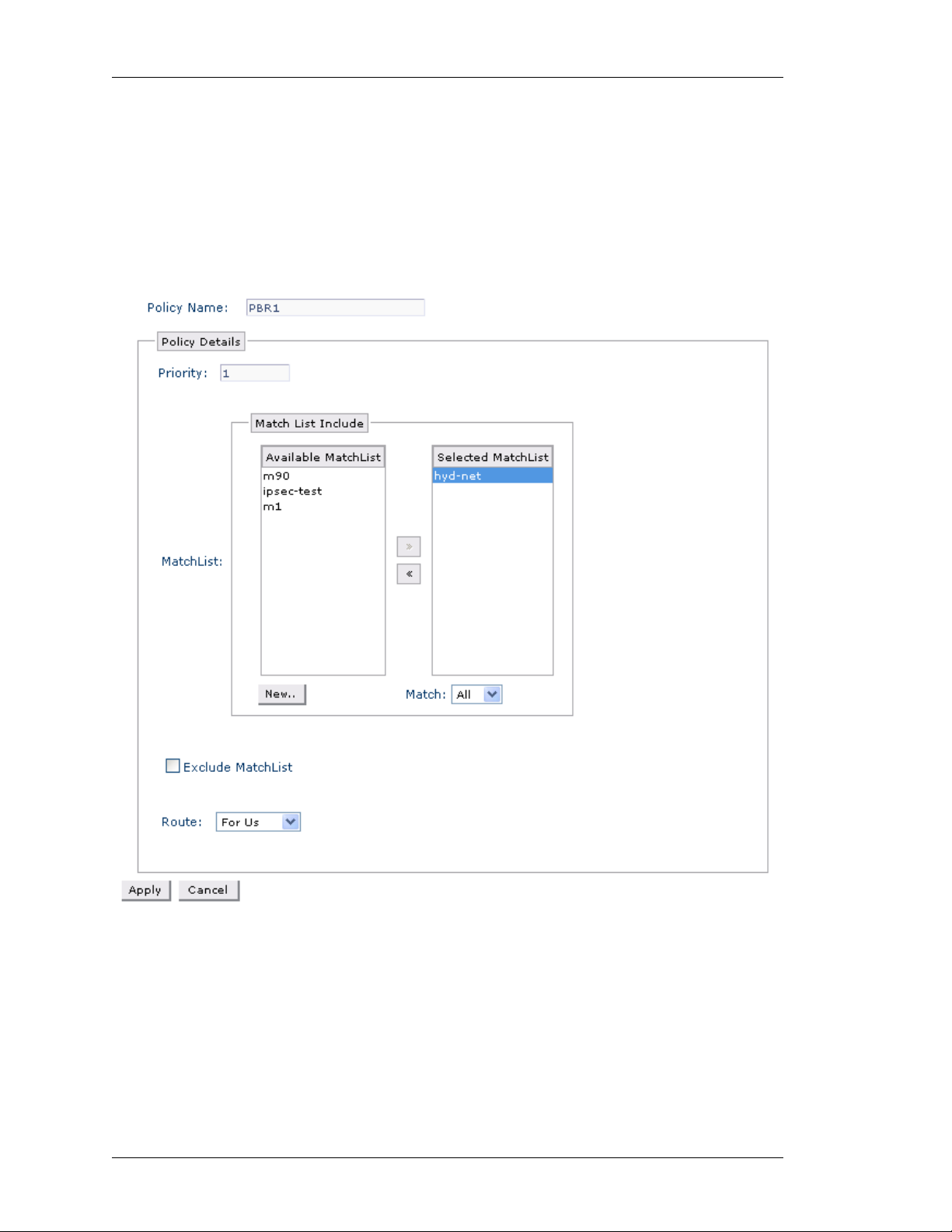
Left running head:
Chapter name (automatic)
Configure
ONFIGURING AN IP POLICY AND A RULE FOR AN IP POLICY
C
Follow the procedure given below to create a new IP Policy and configure a rule
for an IP policy:
Step 1: Click New Policy in the Policy Based Routing page to create a new IP
policy.
Step 2: The following page is displayed:
84
Figure 46: Policy Based Routing - Create New IP Policy
Alcatel-Lucent
Web GUI User Guide
Beta Beta
Page 93

Except on the first page, right running head:
Heading1 or Heading1NewPage text (automatic)
Configure
Step 3: Enter the name for IP Policy in the Policy Name field.
Step 4: Configure a rule for the IP policy. Specify the match conditions and
forwarding action for the IP policy.
1. Enter the priority of the rule in the Priority field.
2. Rule can have multiple match-lists along with the option of any/all. Match List
Include table displays a list of match-lists already configured in the system.
• Select the match-list to be included from the A vailable MatchList colu mn and
click the ‘>’ button to move it to the Selected MatchList column. Select as
many match-lists from the Available MatchList column and move it to the
Selected MatchList column.
• Select the option Any/All from the Match drop-down list.
• Click New to configure new match-lists or if there are no match-lists
configured. Create Traffic Classifier pop-up window is displayed.
Figure 47: Policy Based Routing - Create New IP Policy - Create New Matchlist
Web GUI User Guide
Beta Beta
Alcatel-Lucent
85
Page 94

Left running head:
Chapter name (automatic)
Configure
3. Select Exclude MatchList check box to exclude a specific match-list. Select the
required match-list from the drop-down list.
You can create a new match-list by clicking New. The newly created match-
list will be displayed in the drop-down list. Select the same to exclude it.
4. Select the route option from the Route drop-down list: For Us/Next Hop
• Select For Us to redirect the packet to the management plane of the OA-700.
• Select Next Hop option. Interface and IP address options are displayed. Select
the required option. Next hop specified the egress path of the packet.
Configure the match-list parameters.
i. Enter the match-list name in the Classifier filed.
ii. Select any of the protocols from the Protocol drop down list.
iii. Select source from the Source drop-down list: HOST/PREFIX. Enter the
source IP address for host, and enter the source address with prefix
length for prefix.
iv. Select the destination from the Destination drop-down list: HOST/
PREFIX. Enter the source IP address for host, and enter the source
address with prefix length for prefix.
v. Click Create. The match-list thus created is displayed in the Available
MatchList column.
Note: The interface-name and/or next-hop shall specify the egress path of the packet.
Only one of next-hop and/or interface or for- us sh all be in effect at any time.
If the interface and next-hop are specified together , then the p acket shall be forwarded
to the specified next-hop on the specified interface.
When the interface option is chosen as Ethernet/VLAN, it is mandatory to specify the
next hop.
Step 5: Click Apply to create a new IP policy or Cancel to cancel the operation.
The IP policy thus configured is displayed in the PBR page. And, the PBR Policy
Details table displays the rule elements configured to the IP policy.
A
DD NEW RULE TO AN IP POLICY
Follow the procedure below to add more rules to an IP policy configured.
1. In the Policy Based Routing page, select the IP policy to which new rule is to be
added.
2. Click New Rule. Page to add new rule is displayed.
3. Configure the required rule elements.
86
Alcatel-Lucent
Web GUI User Guide
Beta Beta
Page 95

Except on the first page, right running head:
Heading1 or Heading1NewPage text (automatic)
Configure
EDITING IP POLICY RULE
1. In the Policy Based Routing page, select the IP policy whose rule details are to
be edited. The rules already configured for the selected IP policy is displayed in
the PBR Policy Details table.
2. Click Edit icon in the Action column to edit the rule details.
3. Edit rule page is displayed. Make the required changes. Policy Name is not
editable.
4. Click Apply to save changes, or Cancel to retain the original settings.
D
ELETING RULE FOR A MATCH-LIST
1. In the Policy Based Routing page, select the IP policy whose rule/s is to be
deleted. The rules already configured for the selected IP policy is displayed in the
PBR Policy Details table.
2. Click Delete icon in the Action column against the rule to be deleted.
3. Confirm at the prompt to delete the rule.
A
TTACH AN IP POLICY TO AN INTERFACE
This command is used to attach an IP policy to an interface.
Note: An interface can have only one IP policy applied on it at any time.
‘Transparent-forwarding’ if in effect shall be cleaned up before PBR is configured.
Step 1: Attach an IP Policy to the interface in the Policy Based Routing table.
1. Select the IP policy to be attached on an interface from the Policy Name list.
2. Click Attach Interface icon. Attach Interface page is displayed:
Web GUI User Guide
Beta Beta
Alcatel-Lucent
87
Page 96

Left running head:
Chapter name (automatic)
Configure
Figure 48: Policy Based Routing - Attach Interface
Step 2: The Policy Name field displays the name of the IP policy. This is not
editable.
Step 3: Click Attach.
Step 4: Field to attach interface is populated. Select the interface from the
Interface list
Step 5: Click Apply to attach the selected interface to the IP policy or click
Cancel to cancel the operation.
D
ETACH IP POLICY FROM AN INTERFACE
1. Select the IP Policy from the Policy list. Click Attach Interface icon.
Interface/s already bound to the selected filter is displayed in Attach
Interface page.
2. Click Detach icon in the Action column to detach the IP policy from the selected
interface.
3. Confirm at the prompt to detach the IP Policy.
D
ELETING IP POLICY
1. Click Delete icon in the Action column against the IP Policy to be deleted.
2. Confirm at the prompt to delete the IP Policy.
88
Alcatel-Lucent
Web GUI User Guide
Beta Beta
Page 97

SYSTEM ACCESS
This page allows you to configure the following in your system:
• SNMP
• Syslog
• File Transfer and Access
SNMP
SNMP (Simple Network Management Protocol) is a request-and-response
protocol that is used in sharing networking information between two or more
network entities. SNMP plays a vital role and serves as the nervous system of
entire network management system. The network management is about keeping
the network up and running, monitoring, and controlling devices in the network
using conventional network technology.
Local management and remote management are the two ways of managing a
device connected to a network. Local mana ge m en t de man ds a human
intervention where the managed object is situated. This becomes cumbersome
when the network devices are more and widespread. Managing such a system
becomes tedious and quite impossible. SNMP comes here handy to manage the
network remotely.
Except on the first page, right running head:
Heading1 or Heading1NewPage text (automatic)
Configure
Using a workstation, running one or more SNMP management applications, you
can monitor and manage network devices running SNMP agent. This information
is used to establish the functioning of the network and also to identify the
problems in the network.
In SNMP, two types of communicating devices exist: Agents and Managers. An
agent provides networking information to a manager application running on
another computer. The agents and managers share a database of information,
called the Management Information Base (MIB).
This page allows you to configure SNMP parameters.
Web GUI User Guide
Beta Beta
Alcatel-Lucent
89
Page 98

Left running head:
Chapter name (automatic)
Configure
IEWING SNMP
V
Step 1: From the USGM menu bar, click Configure. All submenu/links under
Configure are displayed in the left navigation panel as shown below.
Step 2: Click System Access sub-menu.
System Access page has three tabs: SNMP, Syslog, and File Transfer &
Access. By default, SNMP tab is active, and its details are displayed in the center
panel.
Figure 49: System Access: SNMP
90
Alcatel-Lucent
Web GUI User Guide
Beta Beta
Page 99

Except on the first page, right running head:
Heading1 or Heading1NewPage text (automatic)
Configure
The table below provides description for SNMP parameters.
Table 9: SNMP Field Description
Field Description
SNMP
SNMP Service Check this check box to enable/disable
SNMP service
Community Settings
Traps Enable Enable SNMP trap
Version SNMP version
Read Community Read community string
Read-Write Community Read-Write community string
Trap Host Configuration
IP Address IP address of the SNMP trap host
Port Port number of the SNMP trap host
SNMP Version SNMP version configured of the trap
host
Community String Community string set on the SNMP trap
host
Action Provides option to edit and/or delete trap
host details
Web GUI User Guide
Beta Beta
Alcatel-Lucent
91
Page 100

Left running head:
Chapter name (automatic)
Configure
ONFIGURING SNMP PARAMETERS
C
Follow the procedure below to configure SNMP parameters:
Step 1: Enable SNMP Service.
To enable the SNMP service, check SNMP Service check box.
Step 2: Configure Community Settings.
1. Select the Traps Enable check box to enable SNMP trapping.
2. Select the SNMP version from the Version drop down list.
3. Enter the Read Only/Read-Write Community string for the SNMP agent.
4. Click Apply to configure Community Settings.
Step 3: Configure SNMP trap host. This is to configure the trap destination where
the agent will send the snmp traps.
If you have checked the Tr aps Enable check box, configure SNMP trap hosts. To
configure new SNMP trap hosts, click New Trap Host in the Trap Host
Configuration box. This populates fields to add SNMP trap host details.
1. The host IP address to which the trap messages are to be sent in the in the IP
Address field.
2. Enter the notification host's UDP port number in the Port field.
3. Select the SNMP version from the SNMP Version drop-down list.
4. Set the SNMP community string in the Community String field.
Note: You can configure a maximum of 3 SNMP trap receivers.
5. Click Apply to add SNMP trap host.
E
DITING A SNMP TRAP HOST
1. Click Edit icon in the Action column against the trap host that is to be edited.
2. Enter the new host details in the respective columns.
IP Address, Port, SNMP Version, and Community String details.
3. Click Apply to save changes, or Cancel to retain the original settings.
D
ELETING A SNMP TRAP HOST
1. Click Delete icon in the Action column against the trap host to be deleted.
2. Confirm at the prompt to delete the SNMP trap host.
92
Alcatel-Lucent
Web GUI User Guide
Beta Beta
 Loading...