

Alaris Imed Gemini PC-2TX Maintenance manual
<x
ALARIS
MEDICAL
SYSTEMS
em»
imc
VOLUMETRIC
INFUSION
Gemini
pc-2Txe
PUMP/CONTROLLER
MAINTENANCE
MANUAL

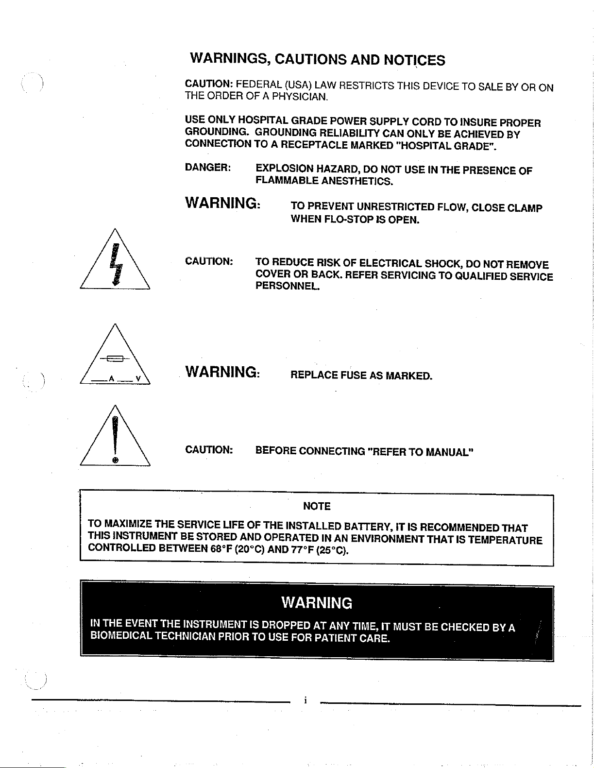
WARNINGS,
CAUTIONS
AND
NOTICES
CAUTION:
ORDER
THE
USE
ONLY
GROUNDING.
CONNECTION
DANGER:
WARNING:
CAUTION:
FEDERAL
PHYSICIAN.
A
OF
HOSPITAL
GROUNDING
TO
A
RECEPTACLE
EXPLOSION
FLAMMABLE
TO
REDUCE
COVER
PERSONNEL.
(USA)
GRADE
TO
PREVENT
WHEN
OR
LAW
RESTRICTS
POWER
RELIABILITY
MARKED
HAZARD,
ANESTHETICS.
UNRESTRICTED
FLO-STOP
RISK
OF
ELECTRICAL
BACK.
REFER
SUPPLY
CAN
DO
NOT
IS
OPEN.
SERVICING
THIS
DEVICE
CORD
ONLY
"HOSPITAL
USE
IN
BE
THE
FLOW,
SHOCK,
TO
TO
TO
INSURE
ACHIEVED
GRADE”.
PRESENCE
CLOSE
DO
QUALIFIED
SALE
NOT
BY
OR
PROPER
BY
OF
CLAMP
REMOVE
SERVICE
ON
|
©
TO
MAXIMIZE
THIS
INSTRUMENT
CONTROLLED
IN
THE
BIOMEDICAL
EVENT
WARNING:
CAUTION:
THE
SERVICE
BE
STORED
BETWEEN
THE
INSTRUMENT
TECHNICIAN
LIFE
68°F
PRIOR
BEFORE
OF
THE
AND
(20°C)
IS
DROPPED
TO
REPLACE
CONNECTING
NOTE
INSTALLED
OPERATED
AND
77°F
WARNING
USE
FOR
FUSE
BATTERY,
IN
AN
(25°C).
AT
ANY
PATIENT
AS
MARKED.
"REFER
IT
ENVIRONMENT
TIME,
IT
CARE.
MUST
TO
MANUAL"
IS
RECOMMENDED
THAT
BE
CHECKED
IS
TEMPERATURE
BY
THAT
A
WARNINGS,
CAUTIONS
AND
NOTICES
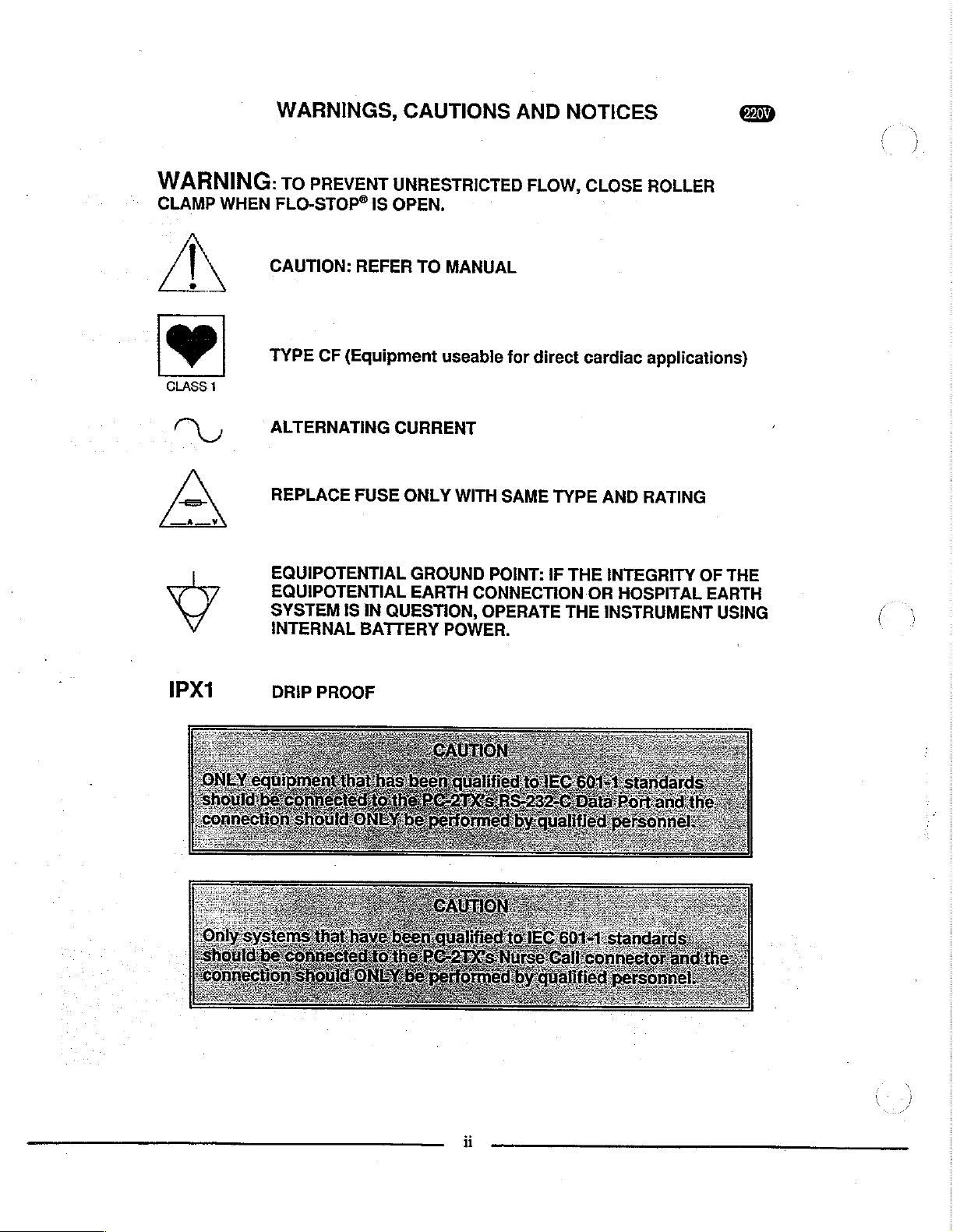
WARNING:
CLAMP
/ | \
ХУ
WHEN
To
PREVENT
FLO-STOP®
CAUTION:
TYPE
ALTERNATING
REPLACE
EQUIPOTENTIAL
EQUIPOTENTIAL
SYSTEM
INTERNAL
CF
IS
REFER
(Equipment
FUSE
IS
IN
BATTERY
UNRESTRICTED
OPEN.
TO
MANUAL
useable
CURRENT
ONLY
QUESTION,
WITH
GROUND
EARTH
POWER.
POINT:
CONNECTION
OPERATE
FLOW,
for
SAME
direct
TYPE
IF
THE
THE
CLOSE
cardiac
AND
RATING
INTEGRITY
OR
HOSPITAL
INSTRUMENT
ROLLER
applications)
OF
THE
EARTH
USING
‘
(os
'
IPX1
DRIP
PROOF
ii
NOTICE
Product
change
in
this
manual
This
publication
Systems™
use
of
technica!
Gemini
design
and/or
without
is
proprietary
infusion
specifications
notice.
current
contains
personnel
The
information
as
of
ALARIS
data
provided
in
the
repairing
pump/controllers.
are
contained
date
of
Medical
solely
IMED®
subject
issue.
for
the
to
None
of
the
duplicated
other
than
Gemini
infusion
component
the
information
substantial
to
user
information
nor
may
it
be
for
the
repair
pump/controllers
parts
thereof.
contained
liability.
contained
utilized
and
in
maintenance
and
Any
unauthorized
herein
may
herein
any
manner
the
subject
may
of
be
IMED®
use
of
the
This
manual
electronic
ALARIS
10221
San
(858)
Medical
Wateridge
Diego,
CA
458-7000
may
not,
in
whole
or
machine-readable
Systems,
Circle
92121
Inc.
USA
or
in
part,
be
copied,
form
without
SCopyright
Printed
U.S.
Patents
4,954,046;
596,552;
1,238,832,
0,225,158;
0,225,158;
TW
UM52721.
###196716885;#885179311985:;4###17303955.
Other
US
IMED®,
2000
in
USA
4,617,014;
4,859,927;
604,477.
AT
283,614;
283,614.
JP
and
Foreign
Gemini
prior
ALARIS
0,225,158.
PC-2TX®
photocopied,
written
Medical
4,689,043;
4,764,166;
CA
1,235,033;
BE
315,312;
CH
0,225,158.
#3
Patents
and
consent
Systems,
4,690,673;
305,151.
1,258,212;
0,225,158.
0,431,726;
DE
17544705;
Issued
Flo-Stop®
FR
0,238,227.
P3686558.3;
and
are
iii
reproduced,
of
ALARIS
Inc.
4,725,205;
AU
1,300,977;
0,225,158;
888181687
Pending.
registered
All
Rights
580,184;
NL
P3772,556.9;
trademarks
Medical
283,614;
0,225,158;
translated,
Systems,
Reserved
4,728,265;
586,594;
1,280,647;
590,179;
1,296,791;
315,312;
283,614.
3871721T2;
25:478190238
of
ALARIS
or
converted
Inc.
4,836,752;
601,664;
2,020,926;
0,431,726;
IT
0,225,158;
Medical
4,909,710;
607,1
0,238,227.
P6908208;
Systems,
to
any
4,920,336;
12;
622,088;
1,296,
283,614.
P3774598.
7%;
092;
GB
SE
Inc.
PC-2TX
This
manual
instructions
of
Volumetric
2TX”).
for
use
servicing
into
seven
Section
Use;
Section 3 -
of
Operation;
Illustrated
and
Preventative
contains
for
Infusion
The
information
by
technical
these
sections
1 -
Description,
Section 5 -
Parts
the
operation
IMED®
products.
Operation;
GEMINI
Pumps/Controllers
provided
personnel
The
and
is
presented
Section 2 -
Maintenance;
Breakdown;
Maintenance.
and
maintenance
PC-2TX®
herein
responsible
material
as
Preparation
Section 4 -
Section 7 -
series
(“PC-
is
intended
for
is
divided
follows:
for
Principles
Section 6 -
Calibration
PREFACE
Additional
by
contacting
Customer
This
Maintenance
copies
Service
manual
your
P/N
1325-9208-00,
The
features
have
been
graphics
model
are
of
incorporated
that
are
identified
of
this
nearest
Department.
143648
Manual,
and
141881.
the
220V
related
with a (AB)
manual
Part
model
into
exclusively
may
ALARIS
supersedes
No.
1325-9201-00,
of
this
be
Medical
PC-2TX
the
PC-2TX
manual.
to
the
symbol.
obtained
Text
or
220V
iv
A
SECTION
| © WARRANTY
7
-
CALIBRATION
7.1
7.2
7.3
7.3.1
7.3.1.1
7.3.1.2
7.3.2
7.4
7.4.1
7.4.1.1
7.4.1.2
7.4.1.3
7.4.1.4
7.4.2
74.3
7431
743.2
AND
PREVENTATIVE
INTRODUCTION
PREVENTIVE
CALIBRATION
Strain
Beam
Calibration
CalibrationProcedures
Door
COMPREHENSIVE
Electrical
ElectricalleakageTest..................................
Electrical
Dielectric
Battery
Qualitative
Quantitative
Eguipment
Test
Equipment
Sear
Adjustment
Inspection
Ground
Test
Runtime
Operational
Reguiremenis
Procedures
に
MAINTENANCE
PROCEDURES
Calibration
Requirements
..................................
................,..................
OPERATIONAL
..................,..,..............
Test
(Optional)
Test
Performance
Operational
MAINTENANCE
ο
...........................
.................................
.......................
PERFORMANCE
Тез
...................
Performance
................................
Test
..................
ἶἶΐἀ{ἶῑῴῄζ{ἵὤζἶἵὤ.
ан,
TEST
нь.
SALES
AND
TECHNICAL
SERVICE
SERVICE
OFFICES
MANUAL
SUPPLEMENTS
vii
PC-2TX
LIST
OF
FIGURES
Figure
1-1
1-2
2-4
2-2
2-3
3-1
4-1
4-2
4-3
4-4
45
4-6
4-7
4-7
4-7
4-8
4-8
4-8
4-8
4-9
49
4-9
4-10
4-10
4-10
6-1
6-2
6-2
6-3
6-4
6-4
6-5
6-6
6-7
6-8
6-9
7-1
7-2
7-3
Title
IMED
GEMINI
Audio
Characteristics
PC-2TX
Air-In-Line
PC-2TX
PC-2TX
PC-2TX
PC-2TX
Cross
Section
AIL
Detector
Slide
Clamp
AIL/SCD
Logic
Board
Logic
Board
Logic
Board
Display
DisplayBoard1320-5049(Sheet20f4)
Display
Display
Power
PowerSuppiyBoard
Power
Motor
Motor
Motor
Parts
Parts
Parts
Parts
Parts
Paris
Parts
Parts
Pertsidentification
Parts
Parts
Universal
Air-in-line
Supply
Supply
Controller
Controller
Controller
Identification
Identification
Identification
Identification
Identification
Identification
Identification
Identification
Identification
Identification
PC-2TX
Model
Front
and
Rear
Simulator
Abbreviated
Front
Panel
Pumping
Signal
Mechanism
Flow
of
Strain
Cross
Detector
Board
Schematic
1340-5048
1320-5048
1320-5048
Board
1320-5049
Board
1320-5049
Board
1320-5049
Board
Board
Board
Board
Board
-
-
-
-
-
-
-
-DisplayBoardCCA
-
Test
Station
Simulator.
Test
Data
Sheet
PC-2TX
..............................,,..,,......,..,,................
Test
Controls
and
Section
Cross
1320-5054
1320-5054
1320-5054
PC-2TX
Front
Front
DOOr
Rear
Rear
Pole
Power
Logic
-
Motor
Setup
Volumetric
Panel
Operating
.........................
Data
Sheet
and
Indicators
.......-.......
Interconnect
Beam
Assembly
........................................................,..
Section
(P/N
1840-5012)
(Sheet
(Sheet
(Sheet
1320-5001
1320-5001
1320-5001
Clamp
............................
t
of
2
of
3
of
(Sheet
(Sheet
(Sheet
CaseAssembiy(Sheet1).
Case
ASSEMblY
Case
Case
1
3
4
(Sheet
(Sheet20f3)............................................
(Sheet
Pump
Assembly
Assembly
Assembly
Assembly
Supply
Board
CCA
Controller
...............,..:.,,,.,.....4......
............................................................
infusion
Features
.................................................
Diagram
.................................
Pump/Controller
.................,..................,..
0
페이
K
n
.......,....,...............................
знании
..........................................
ани
иен
нуна
0...
...................................................
.............................................
3)
.............,................................,...
8)
..................................................
3)
.....................,............................
of
4)
...........................,....................
............................................
of
4)
................................................
of
4)
....................,......................,....
1
of
8)
...........................................
3
of
3)
........,..................................
(Sheet
(Sheet
(Sheet
Board
1
0Î
3)
.......,.............
2
of
3)
...............,....,....................
3
of
8)
.........................................
Assembly
e
CCA
.
.......,...,...............................
...................................
(Sheet
{Sheet
(Sheet
..........,.............,......................
CCA
..............................................
2).
.....................................
1)
......................................,
2)
.......................................
......,..............,.....................
..........................,......,.......,....
1...
eee.
eneret
ere.
lee
a
eve
Page
1-6
2-2
2-6
2-7
3-2
4-2
4-3
4-5
4-9
4-10
4-11
4-15
4-17
4-19
4-21
4-23
4-25
4-27
4-29
4-31
4-33
4-35
4-37,
4-39:
6-4
6-7
6-9
6-12
6-15
6-17
6-19
6-26
6-29
6-35
6-41
7-5
7-7
7-8
LIST
OF
TABLES
Table
1-1
1-2
1-3
1-4
3-1
3-2
4-1
5-1
5-2
5-3
6-1
6-1a
6-2
6-3
6-4
6-5
6-6
6-7
6-8
6-9
Title
Product
Operating
Performance
ο
Description
Visual
RS-232-C
Troubleshooting
PC-2TX
Table
Paris
Parts
Parts
Partslist-DoorAssembiy.................................
Paris
Parts
Parts
Paris
Parts
Paris
History
Reguirements
ος
αμ
MessageDisplays
Communications
Error
of
Torque
List
-
List
-
List
-
List
-
List
-
List
-
List
-
List
-
List
-
............................................4.4..
Specifications
of
Controls
Guide
Log
Codes
Values
PC-2TX
PC-2TX
Front
Rear
Pole
Power
Display
Logic
Motor
Pump
Pump
Case
Case
Clamp
Supply
Board
Board
Controller
........................
............................,..........................
and
Indicators
.................................
Data
ss
............,.......,.................................
Assembly
Assembly
Assembly
Assembly
Assembly
Boardg
CCA
CCA
Board
............,..................................
Port
Signal
eee
..........................................
220V
.
...........,...,..........,..........................
..............,...,..................................
.....................................................
CCA
に
CCA
Definitions
νι
eee.
.........,......................................
1.000.
............................
νεο
ον
ων
00000
1...
0.00
la
eo
n
iii
ee
k
Page
ee.
ED
2
2,
k
eo
이
k
k
k
ος
nn
τς
이
1-4
1-5
1-5
1-7
3-3
3-51
4-13
5-7
5-10
5-27
6-2
6-2
6-5
6-11
6-13
6-14
6-21
6-27
6-30
6-36
PC-2TX
ie
El
GoD
GEES
리디아
imed
|o
O
리사
sm
vem O a
Gemini
000
Gü
上
Pc2Tx
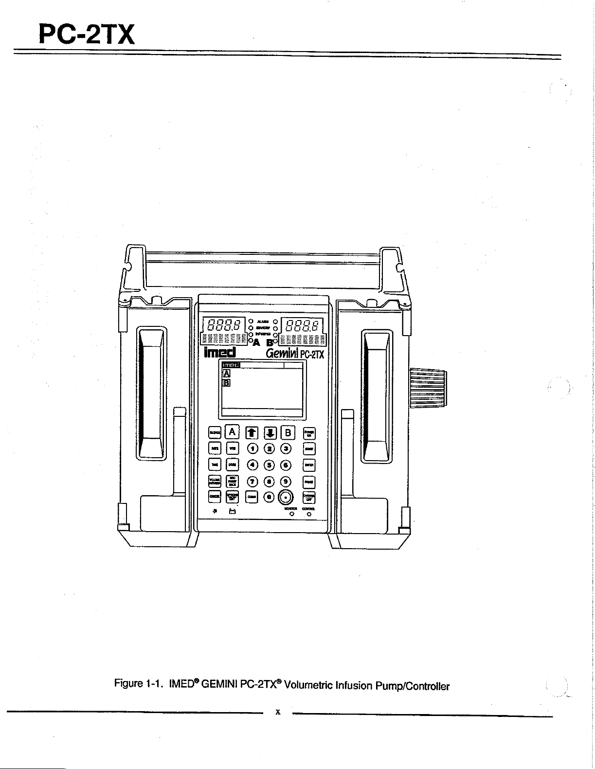
Figure
1-1.
IMED®
GEMINI
(>)
Hooon
“DEDO
re
PC-2TX®
Of)
©
06000)
fO®
519000
Volumetric
x
Infusion
Pump/Controller

PC-2TX
1.1
INTRODUCTION
This
section
physical
istics,
all
cations
PC-2TX®
for
Volumetric
2TX").
1.2
OPERATING
The
GEMINI
volumetric
administration
Both
operation
mode.
peristaltic
by a series
sequentially
action,
administration
pressure
inlet
continuous
accurately
The
infusion
simultaneous
Independent
can
contents
ALL
Empty
an
available
secondary
defined
and
infusion
channels
in
The
pumping
action.
of
the
soft
at
the
side
of
the
flow
and
two
channel
techniques
deliver
setting
secondary
either
("ALL")
requires
Container
as
(piggyback)
delivery
channel.
Operational
through
of
the
“the
rear
instructions
instrument
16
bit
includes
contro!
the
control
instrument
of
the
are
case.
micro-processor
a
Maintenance
includes
description
versions
general
of
Infusion
CHARACTERISTICS
Model
either
collapse
and
an
PC-2TX
pump/controiler
of
intravascular
are
capabie
the
Pump
mechanism
The
peristaltic
12
cam-actuated
then
pumping
set.
This
outlet
side
pump,
of
with a high
primary
optional
thereby
infusion
configuration
including
and
simultaneous
a
specified
of
a
solution
installation
Detector
infusions
parameters,
solutions,
of
the
and
and
the
instrument.
printed
on
Functional
with
operating
operating
and
IMED®
the
Pump/Controller
is a two
drugs
of
independent
or
Controller
employs
action
fingers
release,
segment
action
produces
and
a
delivering
vacuum
solutions
degree
enables
independent
sequential
primary
volume
container.
and
(ECD)
accessory.
with
for
both
can
be
provided
PC-2TX
indicator
Audio
Basic
the
mode
panel
Control
operating
right
control
a
stored
to
monitor
SECTION
character-
specifi-
GEMINI
(PC-
channel
used
in
the
and
fluids.
delivery
linear
is
provided
that
in a ripple-like
of a GEMINI
a
positive
on
the
a
reliably,
of
safety.
a
variety
primary,
secondary.
infusions
or
the
entire
Use
of
the
connection
which
Sequential
independently
the
primary
is
affected
on
switch
side
of
is
provided'by
program
instrument
is
on
the
the
of
each
front
on
that
of
1
-
DESCRIPTION
a
performance,
alert
operators
redundancy
1.3
OPERATING
The
PC-2TX
{Normal
device
includes
Maintenance
Monitor
NORMAL
SYSTEM
The
e
ο
9
.
e
The
current
To
and
Operation)
(Computer
the
and
OPTIONS
systems
Adjust
Set
Enable
Set
Check
System
status
enter
the
hold
the
OPERATION
up.
Bold
face
type
settings.
る
9
Clock
Factory
NO
e
Maximum
mL/hr
e
ο
9
C2
Aux
PCS
Port:
an
audio/visual
to
abnormal
checks
to
confirm
CONDITIONS
can
be
operated
or
as
Operation).
Controller
mode.
Computer
option
contrast
the
Time
Anesthesia
up
Computer
System
Configuration
of
the
and
Computer
Control
mode
of
of
Day
Configuration
following
NOTES
Configuration
"OPTIONS/EDIT"
indicates
Setup:
Set:
Military
Factory
Rate:
Baud
300,
9600,
Port:
Mode:
mode
N81);
No
P
19200;
Serial
Port
or
selection
lock/unlock
alarm
subsystem
conditions
system
independently
a
computer
Normal
Pump
allows
the
LCD
clock
Mode
Control
screen
selectable
Setup
controlled
modes
operation
modes.
the
operator
display
displays
mode:
switch
factory-default
or
AM/PM
Max
C
or
default
usable
600,
(Data
No.
S
settings
rate
1200,
Frame
XXXX.
Channel
plus
mode
and
accuracy.
operation
plus
a
includes
to:
the
features:
press
at
power
YES
1-999
2400,
4800,
is
set
:
delivery
to
or
to
1-1
PC-2TX
®
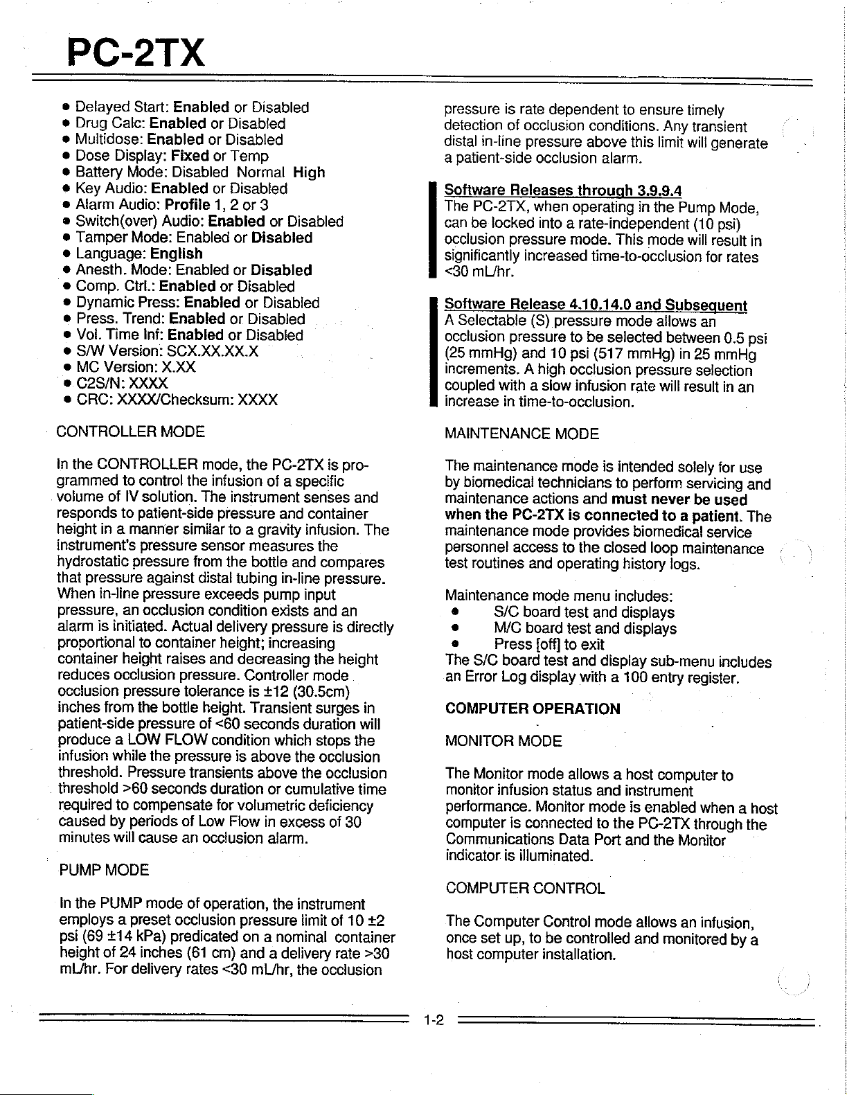
Delayed
e
Drug
Calc:
e
Multidose:
e
Dose
e
Battery
e
Key
Audio:
e
Alarm
®
Switch(over)
e
Tamper
e
Language:
9
Anesth.
e
Comp.
®
Dynamic
e
Press.
e
Vol.
Time
e
S/W
Version:
e
MC
Version:
e.
C2S/N:
e
CRC:
Start:
Enabled
Enabled
Enabled
Display:
Mode:
Fixed
Disabled
Enabled
Audio:
Trend:
Audio:
Mode:
English
Mode:
Ctrl.:
Enabled
Press:
Inf:
X.XX
Profile
Enabled
Enabled
Enabled
Enabled
Enabled
SCX.XX.XX.X
XXXX
XXXX/Checksum:
or
Disabled
or
Disabled
or
Disabled
or
Temp
Normal
or
Disabled
1, 2 or
Enabled
or
Disabled
or
Disabled
or
Disabled
or
or
Disabled
or
Disabled
XXXX
High
3
or
Disabled
Disabled
pressure
detection
distal
a
patient-side
Software
The
can
occlusion
significantly
<30
Software
A
Selectable
occlusion
(25
incremenis. A high
coupled
increase
is
of
in-line
Releases
PC-2TX,
be
locked
pressure
mUhr.
pressure
mmHg)
with a siow
in
rate
occlusion
pressure
occlusion
when
into a rate-independent
increased
Release
(S)
and
time-to-occlusion.
dependent
conditions.
above
alarm.
through
operating
mode.
time-to-occlusion
4.10.14.0
pressure
to
be
10
psi
(617
occlusion
infusion
to
ensure
Any
this
limit
3.9.9.4
in
the
This
mode
and
mode
allows
selected
mmHg)
pressure
rate
will
timely
transient
will
generate
Pump
Mode,
(10
psi)
will
result
for
rates
Subsequent
an
between
in
0.5
25
mmHg
selection
result
in
an
in
psi
CONTROLLER
In
the
CONTROLLER
grammed
volume
responds
height
instrument's
hydrostatic
that
When
pressure,
alarm
proportional
of
in a manner
pressure
in-line
is
initiated.
container
reduces
occlusion
inches
patient-side
occlusion
from
MODE
to
control
IV
solution.
to
patient-side
pressure
pressure
against
pressure
an
occlusion
to
container
height
pressure
the
pressure
produce a LOW
infusion
threshold.
threshold
required
caused
minutes
PUMP
In
employs a preset
psi
height
mU/nr,
the
(69
while
Pressure
>60
to
by
will
MODE
PUMP
+14
of
24
For
periods
delivery
the
seconds
compensate
cause
mode
kPa)
inches
mode,
the
infusion
The
pressure
similar
sensor
from
the
distal
exceeds
condition
Actual
raises
bottle
FLOW
pressure
delivery
height;
and
pressure.
tolerance
height.
of
<60
condition
transients
duration
for
of
Low
an
occlusion
of
operation,
occlusion
predicated
(61
cm)
rates
<30
the
PC-2TX
of a specific
instrument
to a gravity
measures
bottle
tubing
and
and
in-line
pump
exists
senses
container
infusion.
input
and
pressure
increasing
decreasing
Controller
is
+12
Transient
seconds
the
mode
(30.5cm)
duration
which
is
above
volumetric
Flow
the
above
the
or
cumulative
in
excess
deficiency
alarm.
the
instrument
pressure
limit
on a nominal
and a delivery
mL/hr,
the
js
pro-
and
The
the
compares
pressure.
an
is
directly
height
surges
stops
occlusion
in
will
the
occlusion
time
of
30
of
10
+2
container
rate
>30
occlusion
MAINTENANCE
The
maintenance
biomedical
by
maintenance
the
when
maintenance
personnel
routines
test
Maintenance
る
ο
ㆍ
The
an
S/C
M/C
Press
S/C
Error
COMPUTER
MONITOR
The
Monitor
monitor
performance.
computer
technicians
actions
PC-2TX
mode
access
and
mode
board
board
[off]
board
test
Log
display
OPERATION
MODE
mode
infusion
Monitor
is
connected
Communications
indicator
COMPUTER
The
once
host
is
illuminated.
Computer
set
up,
to
computer
CONTROL
Control
be
installation.
MODE
mode
is
to
must
and
connected
is
provides
closed
the
to
operating
menu
includes:
iest
and
test
and
to
exit
and
display
with a 100
allows a host
status
and
mode
to
the
Data
Port
mode
controlled
intended
perform
never
to
biomedical
loop
history
displays
logs.
displays
sub-menu
entry
computer
instrument
is
enabled
PC-2TX
and
the
allows
and
monitored
solely
for
use
servicing
used
be
patient.
a
service
maintenance
includes
register.
to
when
a
through
Monitor
an
infusion,
by
and
The
host
the
a

1.4
USER
Instrument
through
information
information
programmed
appropriate
be-Infused
channel.
(piggyback)
the
primary
Visual
accompanying
operators
infusion
software-detected
both
malfunctions
Delayed
infusions,
programmed
The
rear
ECD
accept a Nurse
communications
сотрщег..
iMED®
sets
Infusion
1.5
PHYSICAL
INTERFACE
control
the
30
keypad
display
displays.
into
keypad
(VTBI)
Rate
and
are
also
infusion
Prompt
audio
connection
and
audio
in
setting
completions,
and
visual
are
signaled
Start,
Multidosing
when
these
via
the
panel
of
for
Call
data
::
GEMINI
are
required
Pump/Controllers.
Series
DESCRIPTION
and
operation
controls,
and
the
independent
Infusion
the
instrument
controls.
are
input
separately
VTBI
for
secondary
programmable,
parameters,
Advisory
alerts
are
up
the
instrument
alarm
malfunctions
conditions
alerts;
by an
and Drug
features
Channel
the
PC-2TX
each
channel, a connector
line,
and a standard
port
for
disposable
for
use
with
is
accomplished
the
central
channel
parameters
using
Rate
and
for
messages
provided
are
are
the
Votume-to-
for
each
infusions
independent
each
channel.
with
to
assist
for
operation.
and
signaled
by
hardware-detected
audio
warning.
Calculation
are
enabled,
Options
is
configured
are
menu.
with
RS-232-C
interfacing
administration
the
GEMINI
with a host
family
an
to
of
of
and
Flo-Stop
central
motor
REAR
The
aluminum
internally:
assembly,
communication
the
module,
power
grounding
1.6
The
Pump/Coniroller
a
Table
1.7
The
subordinated
Performance
Tables
1.8
The
are
control
CASE
rear
rear
cord
PRODUCT
initial
number
1-1
OPERATING
PC-2TX
ACCESSORIES
accessories
listed
detectors,
displays,
CCA.
case
assembly
shell
the
battery,
audio
case
supports
ECD
storage,
retention
point
release
of
changes
for
product
Operating
into
Specifications
1-2
and
in
Table
keypad,
the
display
which
oscillator,
harness
bracket
on
the
CCA,
consists
mounts
transformer
power
assembly.
the
pole
power
220V
HISTORY
of
the
GEMINI
was
in
April
have
occurred.
history.
SPECIFICATIONS
Specifications
Operating
1-3
respectively.
approved
1-4.
Requirements
which
for
the
logic
of
and
supports
harness
supply
clamp,
cord
retention
and
the
model.
PC-2TX®
1994.
are
use
with
channel
a
die-cast
The
equipotential
and
CCA
and
CCA
exterior
power
entry
strap,
Infusion
Since
that
time
Refer
to
are
and
delineated
the
PC-2TX
and
of
in
The
PC-2TX
characteristics:
Height:
Width:
Depth:
Weight:
The
PC-2TX
assemblies:
FRONT
The
injection
and
the
CASE
front
case
molded,
supports:
peristaltic
transducers
instrument
10.8
inches
11.8
inches
7.3
inches
=18
pounds
cord
instrument
the
front
and
consists
plastic
the
pumping chamber
pumping
(strain
beams),
has
the
following
(27.4
cm)
(30.0
cm)
with
(18.5
cm)
with
(8.2
kg)
including
consists
rear
of
two
cases.
of a metalized,
case/insert
mechanisms,
which
access
pressure
Air-in-line,
physical
-
pole
clamp
pole
clamp
power
major
high-impact,
houses
doors,
Slide
clamp
PC-2TX
1325A
1325B
1325C
1325D
The
Systems
Revision
Revision
1325BX
1325CX
1326AX
1
Model
current
Options
Matrix:
#
1325A
1325B
(220
1325C
(220
1325D
(220
PC-2TX
Menu,
System
then
PC-2TX
3.9.9.4,
4.5.24.0,
4.12.9.0,
5.2.4.0
4.2.8.0,
Table
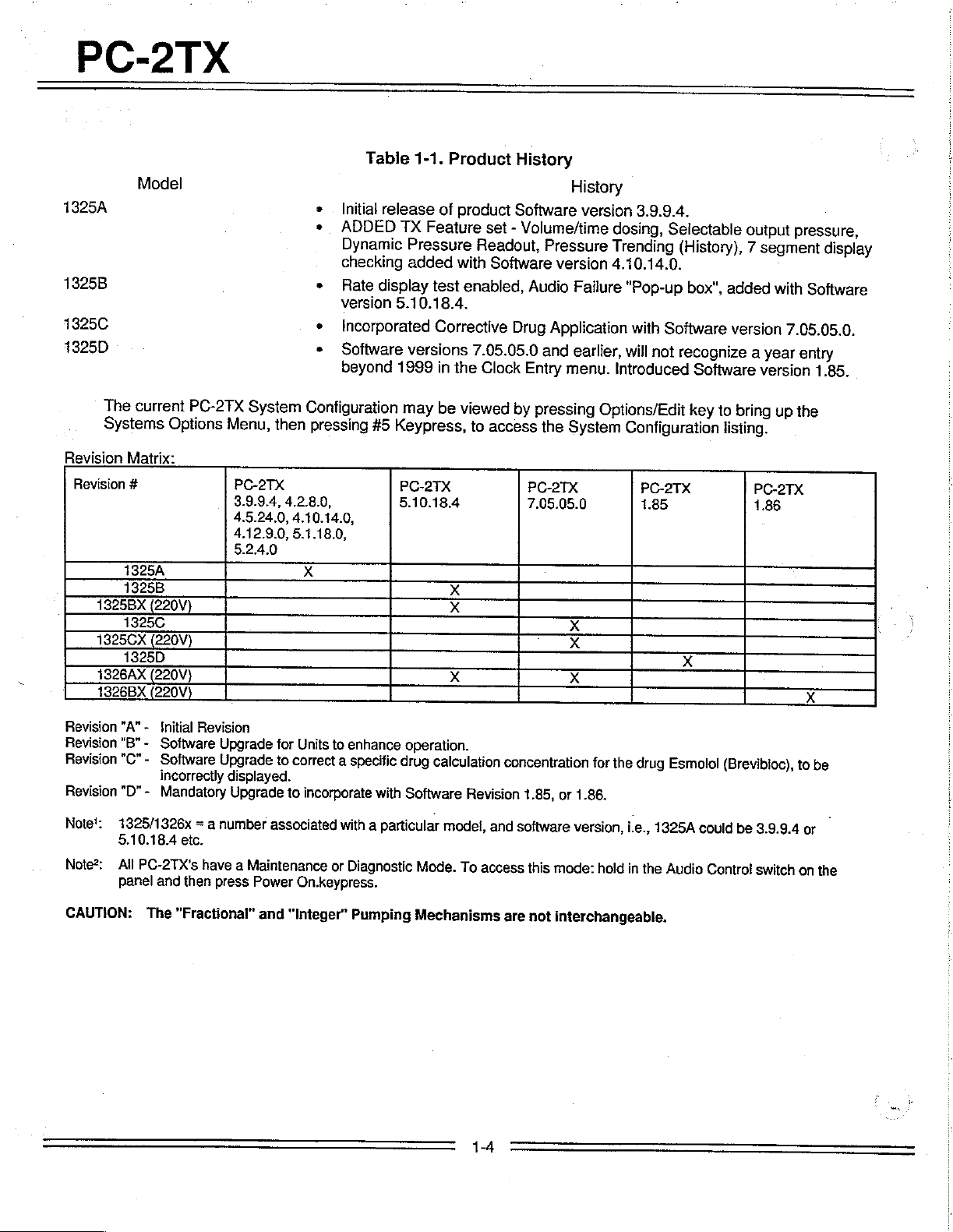
Initial
ADDED
Dynamic
checking
*
Rate
version
«
Incorporated
*
Software
beyond
Configuration
pressing
4.10.14.0,
5.1.18.0,
#5
X
1-1.
release
TX
Feature
Pressure
added
display
5.10.18.4.
versions
1999
may
Keypress,
PC-2TX
5.10.18.4
Product
of
product
set
Readout,
with
Software
test
enabled,
Corrective
7.05.05.0
in
the
Clock
be
viewed
to
access
History
History
Software
-
Volume/time
version
Pressure
version
Audio
Failure
Drug
Application
and
earlier,
Entry
menu.
by
pressing
the
System
PC-2TX
7.05.05.0
3.9.9.4.
dosing,
Trending
Selectable
(History),
4.10.14.0.
“Pop-up
with
will
box",
Software
not
recognize
Introduced
Options/Edit
Configuration
added
version
Software
key
to
bring
listing.
output
7
segment
with
7.05.05.0.
a
year
version
up
pressure,
display
Software
entry
1.85.
the
Revision
Revision
Revision
Revision
Note’:
Note
CAUTION:
"A" - Initial
"B" - Software
"C"-
"D"-
1325/1326x
5.10.18.4
All
PC-2TX's
panel
The
Revision
Software
incorrectly
Mandatory
= a
etc.
have
and
then
“Fractional”
Upgrade
Upgrade
displayed.
Upgrade
number
a
Maintenance
press
Power
and
for
Units
to
to
correct
to
incorporate
associated
or
On.keypress.
“Integer”
enhance
a
specific
with
with
a
particular
Diagnostic
Pumping
operation.
drug
calculation
Software
model,
Mode.
Mechanisms
concentration
Revision
and
To
access
are
1-4
1.85,
or
software
this
mode:
not
interchangeable.
for
the
1.86.
version,
hold
drug
ie.,
in
the
Esmolol
1325A
Audio
(Brevibloc),
could
be
Contro!
to
3.9.9.4
switch
or
on
be
一
the
PC-2TX
Power
_
Rated
Electrical
Electrical
Level
Shock:
Level
ingress:
Battery:
Parameter
Required:
Input
Power:
Leakage:
Shock
of
Protection
of
Protection
Protection:
against
against
Electrical
fluid
ED
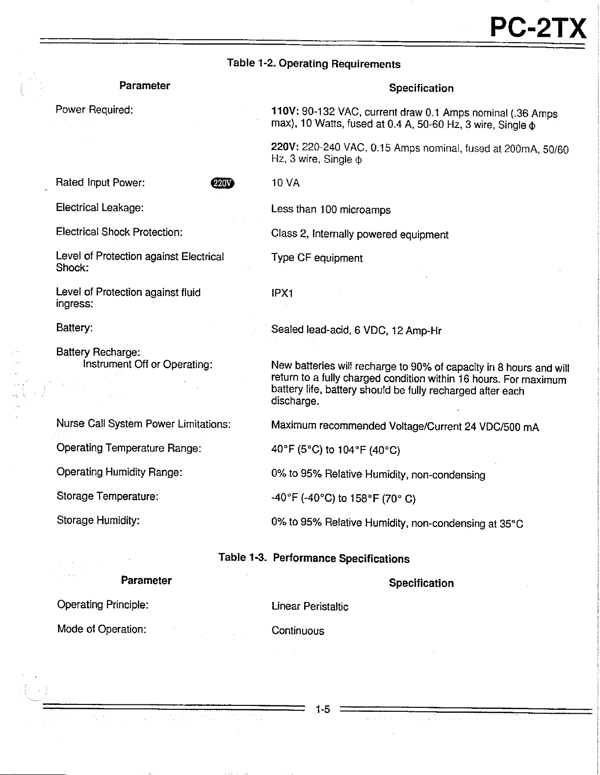
Table
1-2.
Operating
110V:
max),
220V:
Hz,
10
Less
Class
Type
IPX1
Sealed
Requirements
90-132
10
Watts,
220-240
3
wire,
Single
VA
than
100
2,
Internally
CF
equipment
lead-acid, 6 VDC,
VAC,
current
fused
at
VAC,
0.15
microamps
powered
Specification
draw
0.1
Amps
0.4
A,
50-60
Amps
12
nominal,
equipment
Amp-Hr
Hz,
nominal
3
wire,
fused
(.36
Single
at
200mA,
Amps
50/60
Battery
Nurse
Operating
Operating
Storage
Storage
Recharge:
Instrument
Call
Temperature:
Humidity:
Operating
Mode
of
Operation:
Off
or
System
Temperature
Humidity
Power
Range:
Parameter
Principle:
Operating:
Limitations:
Range:
Table
New
return
battery
discharge.
Maximum
40°F
0%
-40°F
0%
1-3.
Performance
Linear
Continuous
batteries
to
a
fully
life,
battery
recommended
(5°C)
to
to
95%
Relative
(-40°C)
to
95%
Relative
Peristaitic
will
recharge
charged
should
to
condition
be
Voltage/Current
104°F
to
Specifications
(40°C)
Humidity,
158°F
Humidity,
(70°
Specification
90%
of
capacity
within
fully
non-condensing
16
recharged
C)
non-condensing
hours.
after
24
VDC/500
in
at
8
hours
For
each
35°C
and
maximum
mA
will
PC-2TX
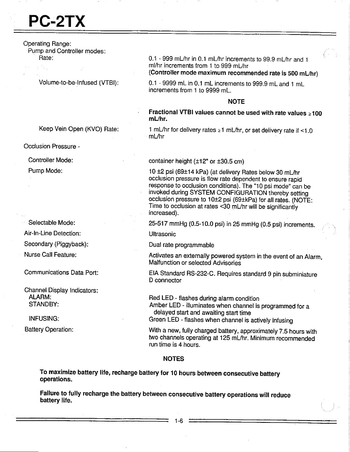
Operating
Pump
Range:
and
Controller
Rate:
Volume-to-be-Infused
Keep
Vein
Occlusion
Controller
Pump
Pressure
Mode:
Mode:
Open
-
modes:
(VTBI):
(KVO)
Rate:
0.1
-
999
mL/hr
ml/hr
increments
(Controlier
0.1 - 9999
increments
Fractional
mL/hr.
1
mL/hr
mU/hr
container
10
+2
occiusion
response
invoked
occlusion
Time
increased).
mL
from 1 to
VTBI
for
delivery
height
psi
(69+14
pressure
to
during
pressure
to
occlusion
mode
in
0.1
from
maximum
in
0.1
mL
9999
vaiues
rates
(+12"
kPa)
is
occlusion
SYSTEM
to
at
rates
mL/nr
increments
1
to
999
mL/hr
recommended
increments
mL.
NOTE
cannot
>
1
mL/hr,
or
+30.5
cm)
(at
delivery
flow
rate
dependent
conditions).
CONFIGURATION
1042
psi
(69+kPa)
<30
mL/hr
be
or
Rates
The
to
999.9
used
set
"10
will
to
99.9
mL/hr
rate
is
mL
and 1 mL
with
rate
delivery
below
to
psi
rate
30
ensure
mode”
mL/hr
thereby
for
all
rates.
be
significantly
and
500
mL/hr)
values
if
<1.0
rapid
can
be
setting
(NOTE:
4
>100
Selectable
Air-In-Line
Secondary
Nurse
Communications
Channel
Mode:
Detection:
(Piggyback):
Cail
Feature:
Display
ALARM:
STANDBY:
INFUSING:
Battery
Operation:
To
maximize
operations.
Data
Port:
Indicators:
battery
life,
recharge
25-517
Ultrasonic
Dual
Activates
Malfunction
EIA
D
connector
Red
Amber
delayed
Green
With
two
run
time
battery
mmHg
rate
Standard
LED - flashes
LED
LED
a
new,
channels
(0.5-10.0
programmable
an
externally
or
selected
RS-232-C.
-
illuminates
start
and
-
flashes
fully
operating
is
4
hours.
NOTES
for
10
hours
powered
Advisories
during
awaiting
when
charged
at
between
psi)
in
25
system
Requires
alarm
condition
when
channel
start
time
channel
battery,
125
mL/hr.
consecutive
mmHg
standard
approximately
(0.5
in
is
programmed
is
actively
Minimum
psi)
the
event
9
pin
infusing
battery
increments.
of
an
Alarm,
subminiature
for
7.5
hours
with
recommended
a
Failure
battery
to
fully
life.
recharge
the
battery
between
consecutive
1-6
battery
operations
will
reduce

PC-2TX
Audio
Characteristics:
AUDIO
(1)
(2)
{3}
(4)
(5)
(6)
(7)
TYPE
MALFUNCTION
KEY
CLICK
ALARM
n
Profile
1
Profile
2
Profile
3
PROMPT
ADVISORY
CHANGEOVER
ILLEGAL
KEY
AUDIO
ΠΠ
600
600
|
30
ΠΠΠΠΠΛΠΠΠῃ
500
500
msec
msec
msec
msec
msec
an
ON
ON,
ON, 3 sec
0.5
(Once)
ON,
1500
ON,
1500
PERIOD
m
LL
400
msec
ON,
1
sec
100
msec
ON,
400
NUL
400
msec
ON,
500
400
msec
ON,
500
LILLA
100
msec
ON,
2
sec
|
100
msec
ON,
15
sec
| | | |
|
100
msec
ON,
400
Il
100
msec
ON,
100
Figure
sec
OFF,
OFF...
msec
msec
OFF,
msec
OFF...
msec
OFF,
msec
OFF...
|
|
OFF...
OFF...
msec
OFF
msec
OFF
1-2.
ПА
OFF,
OFF...
|
|
(6
beeps}
(2
beeps)
Audio
ом
OFF
ON
OFF
ON
OFF
om
OFF
on
OFF
ON
OFF
ON
OFF
ON
OFF
on
OFF
Characteristics
VOLUME
VAR/FIXED
MAXIMUM
75db
FIXED
VARIABLE
VARIABLE
VARIABLE
VARIABLE
VARIABLE
VARIABLE
VARIABLE
VARIABLE
SILENCE
YES/NO
NO
NO
YES
YES
YES
YES
YES
YES
No
Part
1303
3299-100
1308
20-2370-7
No.
Table
Description
Communications
Calibrated
Universal
Syringe
Tubing
Empty
Holder
1-4.
Accessories
Emulator
(optional)
Container
Plug
1-7
(optional)
Detector
(ECD)

PC-2TX
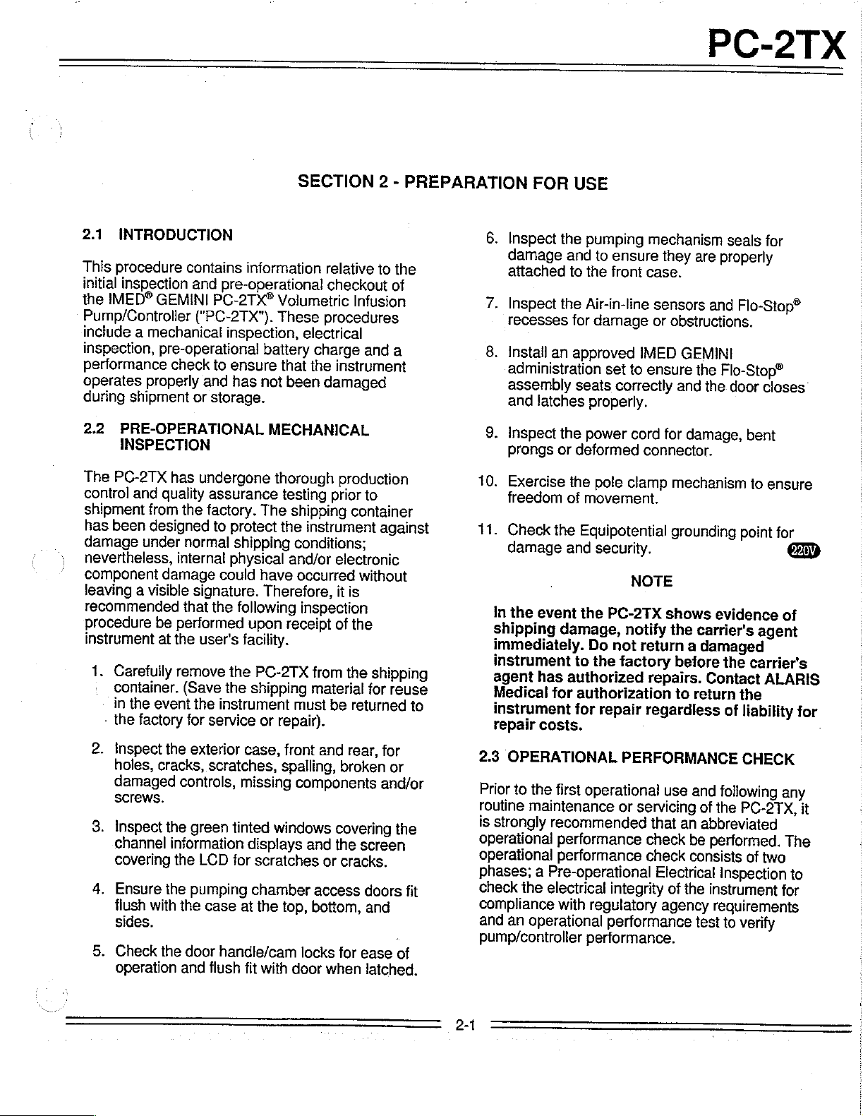
2.1
INTRODUCTION
This
procedure
initial
inspection
IMED®
the
Pump/Controlier
include
inspection,
performance
operates
during
2.2
GEMINI
mechanical
a
pre-operational
check
properly
shipment
PRE-OPERATIONAL
INSPECTION
The
PC-2TX
control
shipment
has
been
damage
nevertheless,
component
leaving a visible
recommended
procedure
instrument
1.
Carefully
:
container.
in
-
the
and
quality
from
designed
under
damage
be
at
the
event
factory
has
the
normal
internal
that
performed
the
remove
(Save
contains
and
information
pre-operational
PC-2TX®
("PC-2TX").
inspection,
ensure
to
has
and
storage.
or
undergone
assurance
factory.
to
protect
shipping
physical
could
signature.
the
following
upon
user's
the
for
facility.
the
the
shipping
instrument
service
SECTION
Volumetric
These
electrical
battery
not
MECHANICAL
The
have
Therefore,
PC-2TX
or
charge
the
that
been
thorough
testing
shipping
the
instrument
conditions;
and/or
occurred
inspection
receipt
from
material
must
repair).
2
relative
checkout
to
Infusion
procedures
and
instrument
damaged
production
prior
to
container
against
electronic
without
it
is
of
the
the
shipping
for
be
returned
-
PREPARATION
the
of
a
reuse
to
FOR
6.
Inspect
damage
attached
7.
Inspect
recesses
8.
Install
an
administration
assembly
and
latches
9.
Inspect
prongs
10.
Exercise
freedom
11.
Check
damage
In
the
shipping
immediately.
instrument
agent
Medical
instrument
repair
the
event
has
for
costs.
USE
the
pumping
ensure
to
and
front
the
to
the
Air-in-line
for
damage
approved
set
seats
correctly
properly.
the
power
or
deformed
the
pole
movement.
of
Equipotential
and
security.
the
PC-2TX
damage,
not
Do
to
the
factory
authorized
authorization
for
repair
mechanism
they
case.
sensors
or
obstructions.
IMED
to
ensure
cord
for
connector.
clamp
mechanism
grounding
NOTE
shows
notify
the
return
repairs.
regardless
・
are
and
GEMINI
the
and
the.
damage,
evidence
carrier's
damaged
a
before
Contact
return
to
seals
for
properly
Flo-Stop®
Flo-Stop®
door
closes
bent
to
ensure
point
for
of
agent
the
carrier's
ALARIS
the
of
liability
for
2.
Inspect
holes,
damaged
screws.
3.
Inspect
channel
covering
4.
Ensure
flush
sides.
5.
Check
operation
the
exterior
cracks,
controls,
the
green
information
LCD
the
the
pumping
the
with
the
door
and
case,
scratches,
missing
tinted
displays
scratches
for
chamber
the
at
case
handle/cam
flush
fit
with
front
and
spalling,
components
windows
and
or
access
bottom,
top,
locks
door
when
rear,
for
broken
and/or
covering
screen
the
cracks.
doors
and
for
ease
latched.
or
the
of
fit
2.3
OPERATIONAL
Prior
to
the
routine
is
maintenance
strongly
operational
operational
phases;
check
the
compliance
operational
an
and
pump/controller
2-1
PERFORMANCE
first
operational
or
recommended
performance
performance
a
Pre-operational
electrical
with
integrity
regulatory
performance
performance.
use
and
servicing
that
check
check
Electrical
of
an
abbreviated
be
consists
of
the
agency
test
CHECK
following
the
performed.
inspection
instrument
requirements
to
any
PC-2TX,
The
of
two
for
verify
it
to
PC-2TX
PUMPING
AIR-IN-LINE
MECHANISM
DOOR
STRAIN
FLO-STOP®
HANDLE
LATCH
BEAM
RECESS
DETECTOR
——-—5
FRONT
STRAIN
UPPER
DOOR
PLATEN
DOOR
MAGNET
DOOR
SLIDE
RELIEF
TUBING
HANDLE
(DOOR
HANDLE
CLAMP
FITMENT
LOCK
SENSOR)
SEAR
ECD
STORAGE
POLE
ECD
CONNECTOR
GHANNEL
NURSE
CONNECTOR
FIXTURE
CLAMP
B
CAL
—
=
一
一
|
=
一
一
一
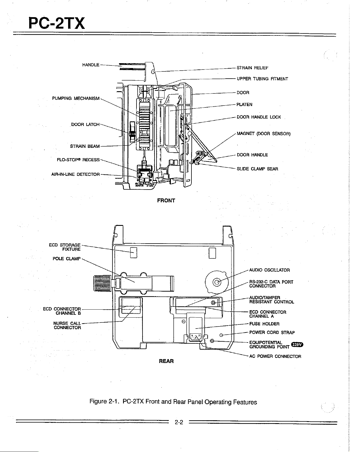
Figure
|
2-1.
PC-2TX
[]
p
AUDIO
SA
LT
Li
[RESISTANT
|
-一 一 FUSE
L_——
el
Features
\
プ
]
Front
REAR
and
©
Rear
o,
Panel
|
Operating
OSCILLATOR
RS-232-C
CONNECTOR
AUDIO/TAMPER
ECD
CHANNEL
POWER
EQUIPOTENTIAL
GROUNDING
AC
DATA
CONNECTOR
A
HOLDER
CORD
POWER
PORT
CONTROL
STRAP
POINT
CONNECTOR
2-2
PC-2TX
2.3.1
The
completion
assurance
time
use,
Pre-operational
batteries
of
inspection.
could
elapse
pre-operational
a
recommended.
suitable
for
2.3.2
The
an
AC
outlet
hours.
24
Pre-operational
pre-operational
electrical
leakage
check.
Some
of
these
Safeguards
should
tests.
qualified
be
Tests
personnel.
are
in
a
post
the
between
Connect
and
electrical
test
CAUTION
tests
for
personnel
employed
should
Check
fully
manufacturing
However,
battery
allow
Electrical
Battery
charged
since
manufacture
charge
the
AC
power
the
battery
Inspection
inspection
and a ground
are
inherently
and
conducting
when
performed
be
only
Charge
condition
quality
considerable
and
is
cord
to
charge
includes
continuity
hazardous.
property
upon
first
to
a
such
by
2.3.3.1
The
supplies
performance
1.
Test
following
are
Two
(2)
(Reorder
Two
(2)
Standard
10
mL
прот
Open-ended
2-2).
6.
Digital
stopcock.
7.
Safety
or
231D
8.
Air-in-line
Requirements
items
of
required
tests:
IMED
#
IV
IV
burette.
to
GEMINI
2210)
Solution
with
Pole.
Air-in-line
Pressure
Analyzer
equivalent.
simulator
gauge,
-
Dynatech-Nevada
laboratory
conduct
equipment
the
administrative
upper
Containers.
simulator
0-60
(see
Figure
operational
sets
injection
sites.
(see
psig
with
Model
2-2).
and
Figure
2.3.2.1
Perform
in
544
Standards
125
Leakage
microamperes.
2.3.2.2
Perform
Electrical
an
electrical
compliance
for
Patient
Association
Risk
for
currents
Electrical
an
electrical
Class
measurement
Care
Equipment
125
for
Risk
Class
impedance
power
case
2.3.3
between
cord
plug
should
not
Abbreviated
Test
The
following
designed
indicators
to
ensure
are
mechanisms
Leakage
leakage
with
Underwriters
Care
Equipment
(CSA)
Equipment
2G
be
to
are
Ground
ground
in
compliance
and/or
and
exceed
CSA
2G
Equipment
the
grounding
the
grounding
100
Operational
operational
that
the
functioning
working
in
are
Test
current
Standard
less
Test
impedance
with
Standard
measurement
Laboratories
and/or
IEC
or
100
than
UL
544
or
IEC
pin
point
milliohms.
Performance
performance
PC-2TX's
properly
controls
and
order.
(UL)
Canadian
C22.2
601-1.
for
Patient
C22.2
No.
601-1.
on
the
on
the
test
is
pumping
all
No.
The
rear
and
2.3.3.2
The
presented
qualitative
INITIAL
PC-2TX
Figure
Test
following
in
check
SETUP
keypad
3-1
and
3-1.
1.
Mount
unplugged).
2.
Fill
IV
fluid
IV
pole
3.
Spike
and
4.
Press
POWER
e
Verify
©
Ensure
displays
e
Ensure
show
® A single
+
The
e
Check
pattern,
below:
Procedures
tests
a
seguence
of
control
are
pump
an
containers
24"
(61cm)
prime
all
LEDs
all
segments
illuminate
the
22 & SESE
audio
channel
the
Central
followed
and
associated
that
provides
instrument
operability.
locations
functionally
IV
pole
above
(leave
with
described
water
PG-2TX.
administration
ON
Control
and
illuminate
of
the
channel
A
information
X
prompt
rate
display
then
sounds
display
by
the
setup
procedures
an
efficient,
are
shown
in
AC
power
and
hang
sets.
check:
then
extinguish
channel
displays
extinguish
shows
for
"-
the
IMED
screen
are
in
Table
cord
on
rate
-
-
-"
logo
shown
2-3
CHARGING
Press
then
press 6 to
Use
the
system
options
Press
shown
to
select
the
select
Ω
configuration
available
twice
above.
INDICATION
controls
and
to
return
Systems
System
to
display
the
status
to
Options
Configuration.
toggle
the
through
to
determine
of
each
Setup
menu,
the
option.
screen
pump
mechanism
the
#11
finger
.
Install a prepared
close
the
door.
container
strain
.
Connect
mL
10
.
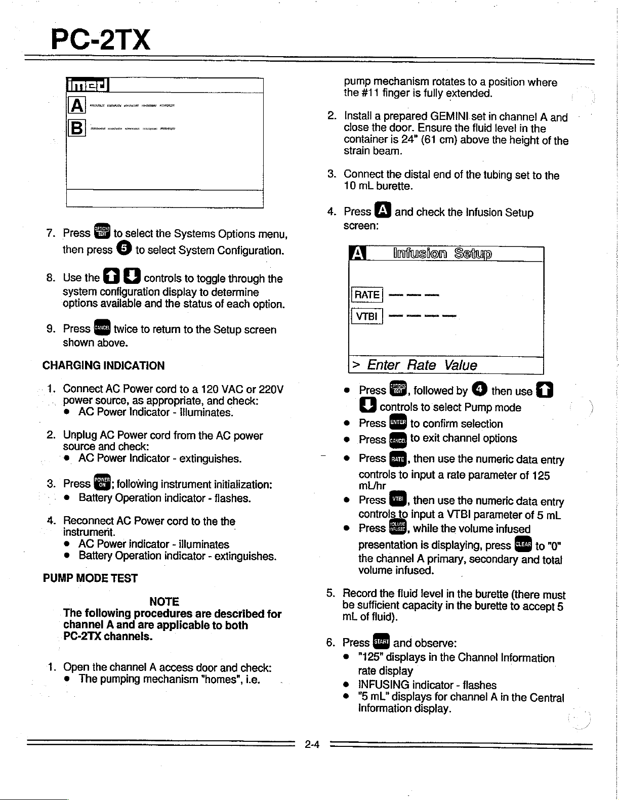
Press o and
screen:
AI
is
beam.
the
burette.
infusion
一
>
Enter
is
fully
Ensure
24"
(61
distal
check
一
ο
ann
Rate
rotates
extended.
GEMINI
the
cm)
end
of
the
Setup
一
или
Value
to a position
set
in
channel A and
fluid
level
above
the
the
tubing
Infusion
Setup
height
in
set
where
the
of
to
the
the
1.
Connect
power
e
AC
Unplug
source
e
AC
Press
Battery
Reconnect
instrument.
e
AC
e
Battery
PUMP
MODE
The
following
channel A and
PC-2TX
1.
Open
©
The
AC
Power
source,
Power
AG
and
Power
a:
Power
the
pumping
as
appropriate,
Indicator - Illuminates.
Power
check:
cord
Indicator - extinguishes.
following
Operation
AC
Power
indicator - illuminates
Operation
TEST
NOTE
procedures
are
channels.
channel A access
mechanism
cord
to a 120
from
instrument
indicator - flashes.
cord
indicator - extinguishes.
applicable
VAC
or
and
check:
the
AC
power
initialization:
to
the
the
-
are
described
to
both
door
and
check:
"homes",
i.e.
220V
for
.
6.
e
Press
8.
controls
e
Press
WS
e
Press
e
Press
controls
mL/hr
e
Press
©.
controls
e
Press
presentation
the
volume
Record
be
sufficient
mL
Press
e
"125"
rate
e
INFUSING
©
"5
Information
Rum
channel A primary,
the
of
fluid).
Qui)
displays
display
mL"
followed
to
select
to
confirm
to
exit
channel
fig,
then
use
to
input a rate
then
use
to
input
a
VTBI
E,
while
the
is
displaying,
infused.
fluid
level
in
capacity
and
observe:
indicator - flashes
displays
display.
in
in
the
for
channel A in
by ο then
Pump
selection
mode
options
the
numeric
parameter
the
numeric
parameter
volume
the
the
Channel
infused
press
secondary
burette
burette
(there
to
Information
the
use
data
of
125
data
of
5
Gag
to
and
accept
Central
entry
entry
mL
"0"
total
must
5
-
2-4
7.
When
COMPLETE-KVO"
O
followed
Rate
"STANDBY"
"INFUSING"
VTBi
Press
PRI
e
audio
display
value
МЗ
(3
and
volume
alert
sounds
scrolls,
by
©
shows
indicator - flashes
indicator - extinguishes
in
Central
check:
infused
and
"1"
check:
display
shows
and
"INFUSION
immediately
5.0.
shows
press
"0
mL”.
MAXIMUM
1.
Initialíze
2.
Press
Displays.
Press ο to
Press
PRESSURE
instrument
©
to
select
select
四
to
select
TEST
in
the
Maintenance
MC
Board
maximum
channel
PC-2TX
Mode.
Tests
and
pressure
A.
test.
Record
compare
step
and
5.25
10.
Repeat
OUTPUT
1.
Connect
pressure
2.
Reset
3.
Press © and
e
Pumping
e
Audio
e
ALARM
e
“OCCLUDED-PATIENT
continuously.
©
Central
for
4.
Record
sheet
must
mmHg).
the
fluid
level
in
that
value
from
5.
The
difference
should
mL.
steps 1 through 9 for
PRESSURE
the
distal
TEST
end
gauge.
the
channel A VTBI
observe:
mechanism
Alarm
sounds
indicator - flashes
Information
channel
pressure
immediately
be
A
gauge
following
between 8 and
the
burette;
the
initial
be
channel!
of
the
tubing
to
25
stops
SIDE"
displays
reading
alarm
12
psi
reading
between
mL.
scrolis
shows
on
the
(reading
or
414
then
B.
set
ALARM
data
and
to
in
4.75
the
620
Press
least
30
pressure
Record
Resultant
mmHg).
Press © twice
Mode
screen.
Turn
stopcock
the
pressure.
Press
instrument.
AIR
IN
LINE
1.
Open
the
the
administration
Install
the
simulator
mechanism,
detector.
and
allow
the
seconds
stabilizes.
the
pressure
twice,
and
highest
to
on
the
then © to
wait
pressure
must
return
pressure
TEST
channel A access
set.
pumping
into
then
segment
the
channel A pumping
press
pump
until
to
the
to
operate
the
reading
be
>17
the
Maintenance
gauge
power
door
and
of
the
tubing
peak
obtained.
psi
(879
to
relieve
down
remove
AIL
into
the
for
the
AIL
at
Push
the
slide
5.
Press
followed
6.
Turn
relieve
7.
Repeat
8.
When
down
to
silence
by
©.
the
stopcock
the
pressure.
steps 1 through 6 for
both
channels
or
the
channel.
as
on
appropriate,
the
audio, then
the
pressure
have
been
then
gatige
channel
tested,
press
B.
press
to
power
c
to
auto
power
Use
the
level
to
Close
the
Select
125
Use
level
the
mL/hr
the
below
the
on
AIL
simulator
top
door.
channel
and
AIL
simulator
the
clamp
in
Alarm
of
the
to
VTBI
AIL
in
(the
instrument
mode).
plunger
slide
clamp
be
tested,
to
50
mL
plunger
detector.
to
raise
fitment.
set
and
press
to
draw
the
the
the
wil!
fluid
rate
a.
fluid
to
PC-2TX
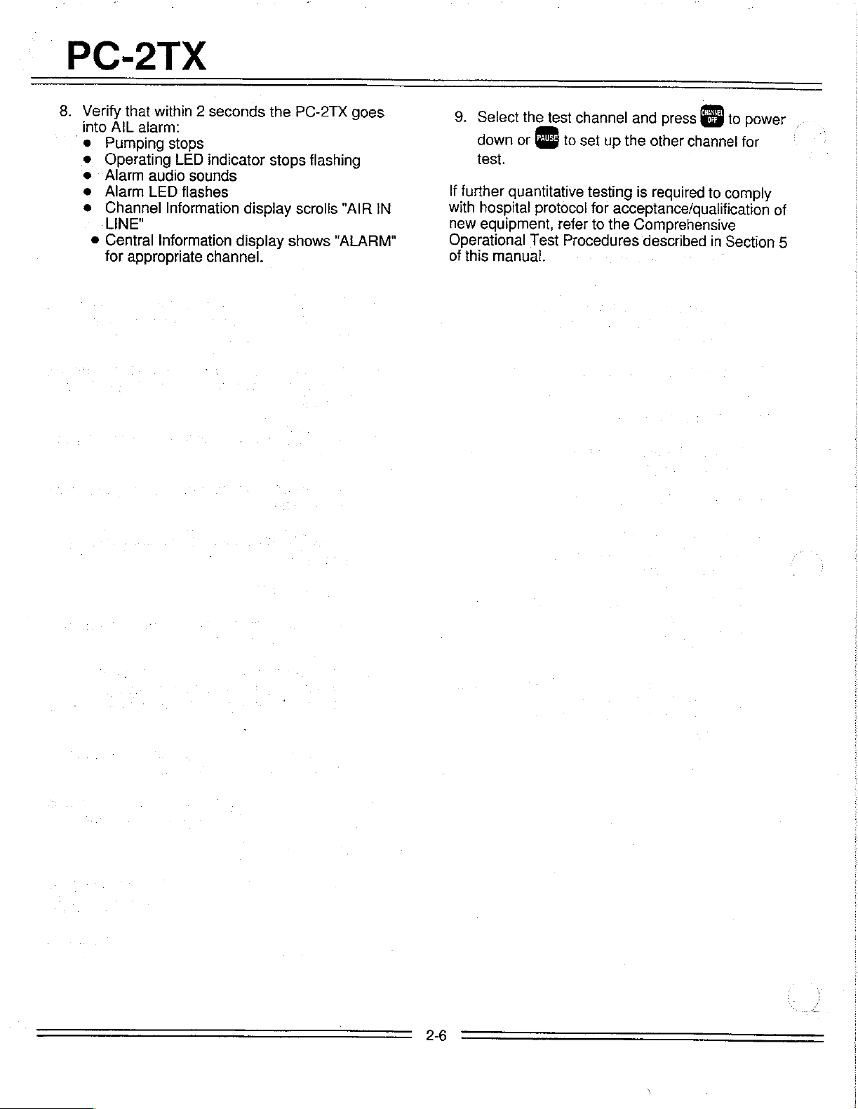
8.
Verify
into
AIL
Pumping
Operating
Alarm
Alarm
Channel
LINE"
e
Central
for
that
within 2 seconds
alarm:
stops
LED
audio
sounds
LED
flashes
Information
Information
appropriate
indicator
display
display
channel.
the
PC-2TX
stops
scrolls
shows
goes
flashing
"AIR
"ALARM"
IN
9.
Select
down
or © to
test.
If
further
with
new
Operational
of
this
quantitative
hospital
equipment,
manual.
the
test
protocol
refer
Test
channel
set
up
the
testing
for
acceptance/qualification
to
the
Procedures
and
press
other
channel
is
required
Comprehensive
described
to
in
to
power
for
comply
Section
of
5
2-6

PC-2TX
JUDO
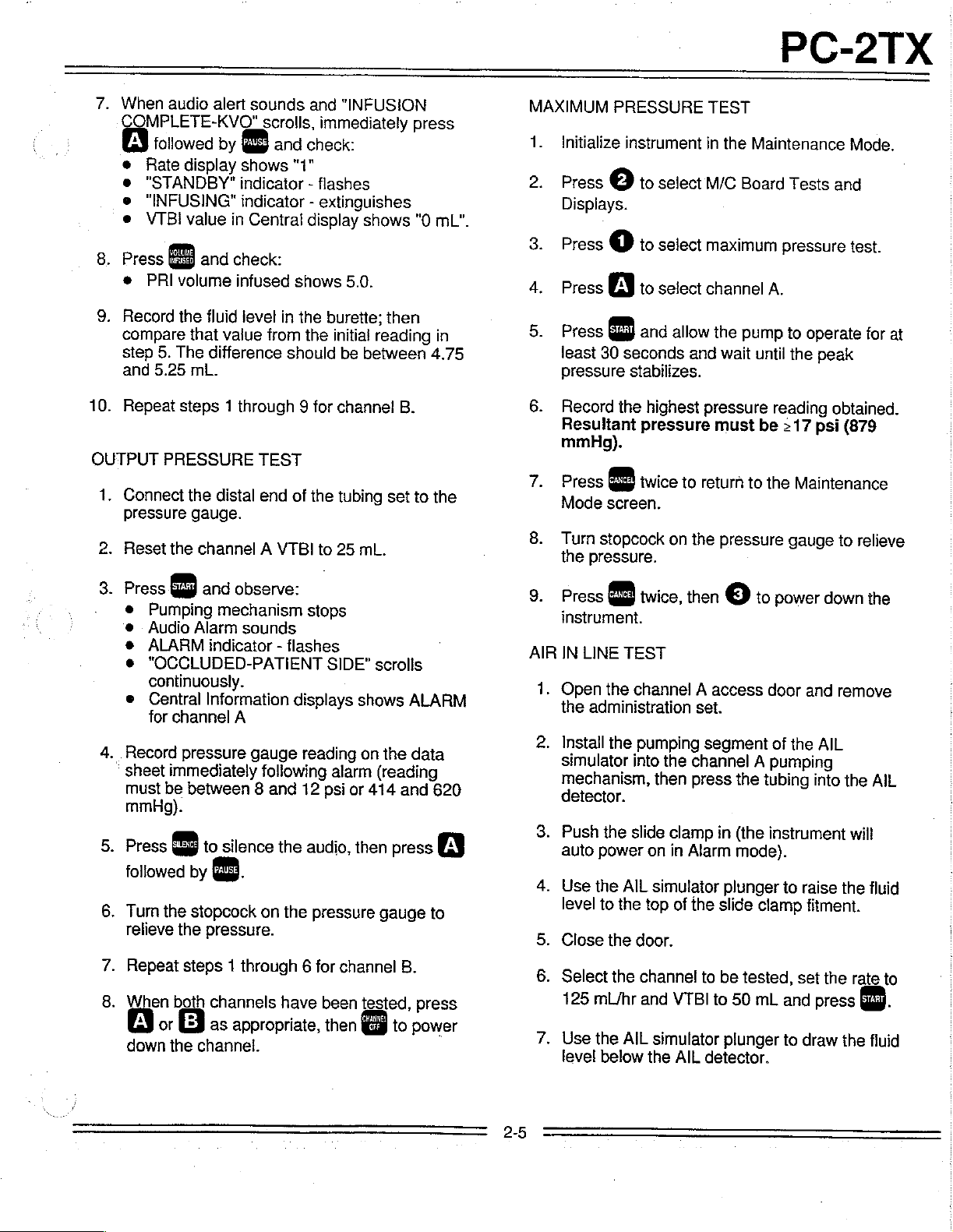
Figure
2-2.
Air-In-Line
Simulator
2-7
 Loading...