

Page 1
imeci
5.1
INTRODUCTION
This
section
instructions,
procedures,
and
reassembly
operational
GEMINI
Potentially
within
performance
PC-2º
the
instrument
AC
power.
for
maintenance
recommended
operated
Printed
damaged
removed
applied
pads
can
metal
foil
that
type
therefore,
irons
and
should
replacing
on
integrated
be
cut
removal.
CMOS
electrical
damaged
activity
protected
ESD
protective
personnel
contains
maintenance
preventive
mode
troubleshooting
procedures
test
Volumetric
Pump/Controller.
WARNING
lethal
voltages
PC-2
case
is
operated
When
using
the
action,
the
instrument
the
internal
CAUTION
circuit
be
before
boards
when
and
replaced.
to
the
circuit
cause
and
base
is
essentially
only
vacuum
used
components
circuit
attempting
(PCBs)
integrated
board
de-lamination
material.
low-temperature
solder
when
removing
on
components
NOTE
devices
is
are
charges
during
not
environment
and
repair
performed
sensitive
procedures
grounding.
SECTION
maintenance
operating
routines,
and a comprehensive
for
when
using
case
it
Excessive
irreparable;
removal
PCBs.
unsoldering
may
if
using
disassembly
the
IMEDS
are
present
the
external
is
opened
is
be
battery.
are
circuits
traces
of
the
Damage
soldering
and
Leads
should
to
be
the
repair
in
an
approved
including
easily
are
heat
and
of
tools
and
static
ESD
5 - MAINTENANCE
5.2
PREVENTIVE
The
GEMINI
with
the
requirements.
incorporates a diagnostic
instrument's
parameters.
irregularities
functional
Alarms
notification.
in
use
troubleshooting
Maintenance-free
scheduled
can
on an
interval
once a year
Verification
responsibility
such
the
graphs
forming
5.2.1
Exterior
using
solutions.
permit
or
the
non-volatile
by
biotechnical
be
‘as
tests
factory
describe
Cleaning
Always
before
sterilize/
Do
solution.
any
cleanup
PC-2
goal
of
The
subsystems
Detection
or
operation
Malfunction
Problems
preventive
enhanced
required’
for
preventive
based
of
proper
of
and
at
nominal
general
unplug
cleaning.
autoclave
not
immerse
surfaces
of
the
This
MAINTENANCE
is
designed
minimizing
integral
routine
and
of
operating
failures
that
activates
alerts
of
RAM
error
this
personnel
and
repair
operation
maintenance
by
performing
basis.
The
maintenance
on
normal
operation
the
user,
verification
cost.
in
detail
the
maintenance
Instructions
CAUTION
the
AC
Do
the
the
of
the
PC-2
following
list
is
considered
of
all
expected
and
assembled
maintenance
microprocessor
that
monitors
operating
system
affect
the
instrument's
audio
and
for
operator
nature
log
actions.
between
At
the
may
The
procedures
on
power
not
instrument.
PC-2
are
for
subsequent
in
performing
regularly
inspections
routine
recommended
inspections
use
and
operation.
is
the
user’s
be
performed
following
the
PC-2.
cord
steam-
in
any
may
be
cleaned
recommended
adequate
contaminates.
the
visual
recorded
cleaning
option,
at
para-
for
per-
to
is
5-1
UPDG3
Page 2
тес]
Isopropyl
Warm
Household
household
These
free
swab.
moved, a cloth
be
and
Then
completely
moistened
water
dried
solutions
cloth; a soft
Once
used
diluting
the
rinses
with a soft,
Prior
the
of
the
electrolyte
female
contamination;
the
alcohol
soapy
water
Bleach
bleach
may
bristle
the
contamination
soaked
to
rinse
the
all
of
the
entire
instrument
rinsed
with
using
fresh
the
instrument
lint
to
reattaching
instrument,
power
and
contacts
power
cord.
(10%
to 9 parts
be
applied
brush
with
entire
residual
another
water.
free
cloth.
WARNING
the
ensure
input
module
dry
thoroughly.
on
the
if
contaminated,
solution,
and/or a cotton
has
fresh
instrument
cleaning
surface
Following
must
AC
that
power
i.e. 1 part
water)
using a soft,
been
water
should
cloth
thoroughly
the
be
thoroughly
power
the
is
clean
Check
cord
lint
re-
should
removing
solution.
be
fresh
cord
to
male base
of
any
the
for
replace
utilizing
(sys
(reading
the
in
the
read
instruments
should
operating
to
check.
should
replaced.
5.2.3.2
1.
2.
the
batt)
test
will
instrument
sestion
5.5
battery
6.5
volts
be
charged
condition,
stabilize
Batteries
be
subjected
Lithium
Turn
instrument
cord
from
Open
the
A/D
terminals.
primarily
for 4 hours
5.5.1).
3.
Connect a digital
(TP3)
and
Board.
Voltage
to
check
be 0.5 true
disassembly
and
display’s
the
battery
voltage),
procedures
connecting a voltmeter
Battery
+0.3
volts.
Batteries
operated
for
12
hours
then
unplugged
prior
to
testing
Battery
to
further
off
less
Check
and
unplug
outlet.
instrument
Vaay
case
voltmeter
(U8,
pin
system
voltage
or
by
voltage
installed
on
battery
in a non-
and
performing
than
62
testing
AC
(see
section
between
16)
on
the
battery
following
described
across
should
in
power
allowed
voltage
volts
or
be
power
ground
Analog
5.2.2
Perform
section
checks:
ㆍ
+
Mechanical
the
mechanical
2.2
of
this
Inspect
excessive
or
damaged
Perform a pumping
spring
roller
the
functioning
Replace
5.2.3
Perform
described
5.2.3.1
Perform a battery
entering
for
Maintenance
the
wear
1000
hours
or
integrity
clamp
Pump
mode.
the
damaged
Electrical
the
standard
in
section
Battery
the
maintenance
Inspection
manual
urethane
and/or
of
instrument
worn
replace
test
while
the
If
channel
or
Inspection
electrical
2.3.2
Voltage
voltage
Mode
inspection
plus
the
pumping
holes
the
mechanism
by
closing
pump
only
one
will
missing
inspections
of
this
Check
check
mode
operating
described
following
seal
for
every
90
operating
seal.
extension
the
IV
is
operating
spring
not
by
(see
procedures)
is
occlude.
spring.
manual.
either
section
in
days
time.
set
in
5.3
and
4.
Disconnect
Power
5.
After
display
the
meter
Volts.
If
6.
Reconnect
POWER
7.
If
the
lithium
should
5.3
MAINTENANCE/DIAGNOSTIC
The
PC-2
Diagnostic
access
the
the
Maintenance/Diagnostic
biotechnician
to
verify
operation
features,
independent
check
access
keypad,
system
the
and
communications
Supply
the
audio
to
stabilize
reading.
ON
voltage
battery
be
replaced.
is
configured
Mode
software
can use
to
operate
of
Analog
error
to
the
battery
Board.
initiates,
(~30
Reading
the
battery
control
reading
that
to
is
(B1)
on
with a Maintenance/
allows
diagnostic
the
diagnostic
of
the
operator
the
pumping
the
alarm/malfunction
to
Digital
log,
to
test
check
port.
the
input
harness
allow
at
the
seconds},
should
harness
silence
<2.25
the
and press
the
Volts,
Logic
Board
MODE
biotechnicians
subsystem.
Mode
is
enabled,
test
interface
mechanisms
interrupts,
voltages,
the
lamps
port
and
J6
on
the
voltmeter
then
note
be
>2.25
audio.
the
to
Once
the
routines
to
and
serial
the
to
UPDD3
5-2
Page 3
Integer
The
selection
parameters.
Keypad/Series
Maintenance
and
to
2.xx
Mode
is
set serial
Software
utilized
communications
for
language
1.
Unplug
recommended
be
possible).
the
performed
AC
power
that
maintenance
using
battery
imed
cord
(it
is
power
operations
whenever
Fractional
The
Setup
and
to
5.3.1
Keypad/Series
Mode
set
communications
Maintenance/Diagnostic
Sequence
Integer
The
the
initialization:
Keypad/Series
Maintenance
following
order
TIMEBASE
LAMP
TEST
KEYPAD
ERROR
MOTOR
PUMP
TEST
SERIAL
A/D
VOLTAGE
INPUT
COMMUNICATIONS
LANGUAGE
POWERDOWN
Fractional
The
following
Keypad/Series
Diagnostic
sequence
initialization:
ERROR
PUMP
MOTOR
A/D
VOLTAGE
INPUT
LAMP
TEST
KEYPAD
TIMEBASE
SERIAL
ROM
CRC DISPLAY
POWERDOWN
5.3.2
Maintenance/Diagnostic
is
Mode
TEST
LOG
HOMING
PORT
PORT
Mode
LOG
TEST
HOMING
PORT
TEST
PORT
3.xx
utilized
2.xx
test
after
Maintenance
CHECK
DISPLAY
TEST
TESTS
DISPLAY
DISPLAY
SELECTION
TEST
test
routines
after
diagnostic
DISPLAY
TEST
DISPLAY
DISPLAY
CHECK
TESTS
TEST
Software
for
language
parameters.
Mode
Software
sequence
SETUP
3.xx
Software
appear
mode
Mode
selection
Test
appears
Mode
in
Operation
in
the
2.
Software
Install
Call/Maintenance
Software
Press
MONITOR
3.
Press
ㆍ
Integer
+
Release
the
Maintenance
Release
and
hold
switch.
the
POWER
All
LEDs
and
seconds
then
Keypad/Series
"maintenance
on
the
Channel B Operator
display
(2.xx
version).
Fractional
+
"diagnostics
Keypad/Series
<stop>" - scrolls
channel B Operator
(v3.xx = installed
4.
The
PC-2
is
now
Maintenance/Diagnostic
Software
The
to
next
5.3.3
The
both
Where
Fractional
feature,
Maintenance
following
the
Release
maintenance
change
v2.xx
differences
both
and
during
procedural
and
keypad
procedures
from
V2.13
Plug
in
Plug
connector
V2.33
the
and
COMPUTER
ON
control
Subsequent
displays - illuminate
extinguish.
2.xx
Software
v2.xx" - scrolls
is
the
installed
3.xx
PC2
v3.xx
to
continuously
Information
software
initialized
version).
in
the
Mode.
NOTE
V2.13
plug
must
be
one
test
routine
the
Mode
steps
v3.xx
software
occur
between
controls
are
motor
used
homing
Test
Suite
are
versions.
the
to
described.
select a test
the
Nurse
(rear
panel).
CONTROL/
and check:
for
continuously
Information
software
Software
exit
press
on
the
display
installed
to
the
test.
applicable
Integer
and
3
to
Performing
will
diagnostic
Prior
to
operating
Maintenance
instrument
the
provide
access
mode
WARNING
the
Mode
is
not
connected
following
to
the
tests:
PC-2
in
ensure
that
procedures
PC-2's
maintenance/
the
the
to a patient.
as
described
Software
The
used
maintenance
Software
The
used
maintenance
5-3
Release
press
function
to
sequence
Release
COMPUTER
to
sequence
V2.13
of
the
through
mode
tests.
V2.33 and
CONTROUMONITOR
through
mode
tests.
Audio
the
individual
Subsequent
the
individual
Control
switch
switch
UPDO3
is
is
Page 4
im
Each
confirmation
pressed
scrolled
displayed
select
test
deselect
in
test
Integer
Actuation
identifier
sequence
Fractional
Diagnostic
Diagnostic
scrolling
routine.
TIMEBASE
1.
Press
and
»
2.
Integer
Fractional
test
routine
is
identified
message.
to
initiate a specific
test
identifier
test
phase
control
the
the
Maintenance
may
current
test
Keypad/Series
of
the
is
or
PAUSE/STOP
scrolling
and
Keypad/Series
mode
mode
via a powerdown
will
powerdown
can
or
powerdown
CHECK
the
appropriate
check:
"timebase
Information
Press
Keypad/Series
*
"running" - displays
«
Channel B VTBI
check" - scrolls
display.
START
and
between 0 and
"failed"
Information
clear
allow
*
"swing" - displays
+
numerical
channel B VTBI
windows.
-
-
-
will
display
display.
the
Operator
the
test
Keypad/Series
values
Press
PAUSE/STOP
display
+
*
If
expected
and
Rate
Pressing
for
data
"(halted)
channel A Operator
press
the
displays
PAUSE/STOP
‘swing’
deviation, a failure
"FAIL"
display.
CLEAR
resume.
by a scrolled
Once
the
START
test
routine,
is
replaced
identifier.
be
used
and
Mode
2.xx
interrupt
the
only
be
test
by a statically
The
appropriate
at
any
proceed
test
sequence.
Software
key
while a test
the
instrument.
3.xx
Software
exited
test
in
the
Pump
select
on
check:
2.xx
Software
statically
display - alternates
1.
If
displayed
on
the
Operator
Pressing
CLEAR
Information
to
resume.
3.xx
Software
statically
sequence
display's
recording.
tenths
once
rapidly
to
statically
Information
again
value
exceeds
appears
in
will
the
allow
channel
key
is
the
time
to
to
the
next
test
when
the
identifier
Test
control
the
value
once
Operator
is
will
display
and
in
and
the
units
freeze
in
the
display
to
unfreeze.
the
is
invoked
B
the
test
to
are
22,
the
Press
the
between
user
between
user
difference
readings
modes.
LAMP
1.
Press
and check:
«
"lamp
Information
Press
2.
+
Rate
sequentially
9 9
(The
display a decimal
position;
Indicator
+
Operator
alphabet
"ου,
*
Controller
Secondary
Traffic
illuminate
test
+
Audio
KEYPAD
1.
Press
and
*
Press
+
Press
provides
or
and
active
corresponding
displays
information
either
display
to
old
keypress),
old
keypress)
between
updated
TEST
(with
the
appropriate
test" - scrolls
START
and
VTBI
followed
channel B VTBI
instead
will
Information
in
"*,
"and
and
cycle
alert - sounds
TEST
the
appropriate
check:
“keypad
Information
"start”
Information
test" - scrolls
START
displays
each
no
COMPUTER
Subsequent)
test)
on
the © or © controls
the
"max"
(maximum
and
new
timer
reading
"min"
(minimum
and
new
timer
or
"dynamic"
old
every
AUDIO)
test
display.
and
check:
displays - Flash
numbers
by
1.1.1.1.
point
the
illuminate)
upper
case,
and
10
on
Operator
1 1
Display
Battery
displays - scroll
difference
reading
(current
new
msec)
seleot control
1 1
through
will
in
the
Operation
the
numbers
"?"
and
Pump
(Piggyback),
Battery
steadily
display
and
display
key
response,
indicator
during
check:
statically
(except
delivery
once
test
on
POWER
Audio
mode,
Communication
LEDs
one
half
per
select control
Operator
on
Operator
Control
CONTROUMONITOR
which
one
nomenclature
the
channel B Operator
display.
always
at a time
terminates
and
verify
for
to
taggle
difference
since
last
since
last
timer
data
once
through 9 9
9.9.9.9.
not
Units
the
"0"
of
the
second.
once
ON
which
(V2.13)
(V2.34
the
that the
the
key
-
UPDO3
5-4
Page 5

ERROR
1.
Press
and
*
2.
Press
+
«
3.
Press
log:
+
4.
Press
+
LOG
DISPLAY
the
appropriate
check:
“error
log
display" - scrolls
information
START
“empty”
(no
display
and
check:
errors
channel B Operator
this
case
proceed
mode
test.
"newest"
"nn:
the
(nn = number
=
error
[v2.xx]
Next
format
followed
ccc"
[v3.xx]
channel B Operator
identification
or
00
Units
(1)
oldest
or
"no
CLEAR
Error
log
clears - "wait"
on
the
Operator
a
one
second
either
“okay”
to
or
by
will
of
entry
to
129
digit
key
entry
will
older“
key
and
Information
verification
or
"fail".
test
select
on
logged)
appears
Information
the
next
"nn:
cc”
display
statically
Information
from
00
code - 00
[v3.xx]).
to
read
display
will
appear.
check:
displays
display
stage
control
Operator
on
once
the
display.
maintenance
[v2.xx]
the
in
to
to
"nn:
or
display
09,
99
error
cc"
on
οσ(ο)
statically
during
followed
In
by
5.
Press
«
Pumping
‘sync’
and
Operator
»
Pumping
“failed”
Information
Software
2.
Press
+
Channel A VTBI
the
"homestep"
channel A Operator
3.
Use
(between 0 and
>199
4.
Press
+
Pumping
selected
display
the
*
Pumping
channel A VTBI
numerical
step
START
“homing”
and
mechanism
position
displays
check:
(number 7 finger
Information
mechanism
displays
Release
START
statically
display.
V2.33
and
check:
and
displays
last
selected
home
displays
Information
the
Data
Entry
Controls
199)
for
will
revert
display
START
and
check:
mechanism
step,
"-
- -
-"
and
"homing"
channel A Operator
mechanism
display
value
of
the
imed
operates
statically
display.
stops and
step
statically
homing. A selection
to
operates
appears
displays
stops
selected
to
seek
extended)
in
the
"homed"
in
the
Operator
Subsequent
either a "0"
and
in
the
display.
to
select a step
"0".
to
seek
in
the
statically
Information
and
the
shaws
the
homing
display.
the
or
or
the
VTBI
in
MOTOR
Software
1.
2.
3.
4.
HOMING
Press
the
and
check:
«
“motor
Operator
Release
Press
START
+
“chan
A*
information
Press
START
+
Pumping
‘sync’
position
and
"homing"
Operator
+
Pumping
“failed”
Informatian
Press
START
*
"chan
B
Operator
TEST
appropriate
homing
test" - scrolls
Information
V2.13
and
displays
display.
and
mechanism
(number 7 finger
displays
Information
mechanism
displays
display.
and
B"
displays
Information
test
select
display.
check:
statically
check:
operates
statically
display.
stops
statically
in
check:
statically
display.
control
on
in
the
to
and
the
in
the
once
channel
Operator
seek
the
extended)
in
the
“homed”
Operator
Channel
B
or
+
"homed"
channel A Operator
«
Press
channel
#4.
PUMP
1.
TEST
Press
and
check:
*
"pump
the
information
Software
2.
Press
+
The
Release
START
upper
CONTROLLER
Rate
indicator
*
"PG-2
Operator
channels
or
"failed"
PAUSE/STOP
B,
then
repeat
appropriate
test"
scrolls
display.
V2.13
and
position
Delivery
illuminates
Vx.xx"
scrolls
Information
displays
Information
once
steps
test
select
on
the
check:
of
either
Mode/Retative
once
display
statically
display
to
select
#2
through
control
Operator
the
PUMP
for
each
across
of
both
in
once
channel
the
UPDO3
the
or
Page 6
imeci
*
"ACCESS
the
channels
+
“MAINTENANCE”
the
channels.
Use
the
section
abbreviated
Operators
operate
The
instrument
independent
Software
2.
Press
+
"normal"
A
Operator
Use
the
select
test
mode.
step
between
mode
channel B Operator
Press
operation.
+
"MAINTENANCE"
both
*
Channel A Rate and
"о"
*
Last
mode/Operating
Use
the
3.3.1
instrument.
When
ACCESS
operation.
When
pressing
following:
+
Calculated
threshold
is
displayed
CHANNEL"
Operator
Operator
detailed
3.3.1.1
Information
Information
procedures
of
procedures
Reference
the
instrument.
will
of
any
Release
START
V2.33
and
displays
Information
Units
(1)
either
the
‘normal’
Each
normal
selected
START
Operator
selected
procedures
to
set
channel A is
will
to
Information
Pump
up
channel A and
CHANNEL
in
the
Pressure
START
occlusion
for
selected
in
scrolls
scrolls
this
manual
described
Guide
NOTE
continue
alarm
and
Subsequent
check:
statically
display.
digit
Data
or
actuation
and
pressure.
display
Information
enable
the
scrolls
VTBI
or
Controller
indicator
described
operating,
B
then
mode
in
step
45
pressure
infusion
the
RATE
once
across
display
of
both
continuously
display
of
described
or
the
in
to
set
up
both
the
and
operating
conditions.
on
the
channel
Entry
Control
‘pressure’
will
alternately
pump
The
statically
on
display.
PC-1
for
continuously
displays
displays
show
delivery
will
illuminate.
in
Section
operate
press
setup
for
and
after
above,
check
voltage
parameters
display
on
in
the
on
the
to
the
»
Voltage
Strain
Any
time
while
in
and
VTBI
selected
VTBI
values.
Three
the
tarily
then
a
mode
the
To
press
switch
routine
motor
pumping
to
resumes
one
time
presentation
infusion
change
COMPUTER
once.
back
communication
the
communications
Fractional
2.
Press
-
3.
Use
the
4.
Press
Keypad/Series
START
"normal"
A
Operator
the
"normal"
START
operation.
+
"MAINTENANCE"
both
Operator
e
Channel A Rate and
+
Operating
selected
5.
Follow
3.3.1
operate
6.
When
pressing
following:
*
the
to
the
in
Calculated
threshold
is
displayed
*
Voltage
Strain
relative
Beam
displays
NOTES
the
pumping
the
pressure
display
infusion
revolutions
mechanism
check
occlusion
operation.
interruption
parameters.
pump
This
to
step
cable
and
displays
Information
or © control
and
"pressure"
to
enable
Information
indicator
delivery
procedures
set
up
channel(s) A and/or B and
instrument.
the
Pressure
START
relative
Beam
in
occlusion
for
selected
in
the
displays
to
pressure
mode,
revert
Rate
sensed
in
the
VTBI
mechanism
the
to
displaying
and
decremented
following
stops
pressure
This
of
the
with a flash
test
mode
selection,
CONTROL/MONITOR
will
loop
the
#3
providing
is
NOT
data
port
3.xx
Software
check:
staticaily
on
display.
to
toggle
options.
the
PC-2
scrolls
continuously
displays
VTBI
displays
illuminates
mode.
described
mode
and
step
#5
above,
pressure
infusion
RATE
to
pressure
in
the
display
sensed
VTBI
at
the
display.
stops
RATE
the
START,
momen-
and
will
result
pressure
display
test
a
connected
(RS-232C).
the
channel
between
for
on
show
for
last
in
Section
after
check
voltage
parameters
at
display.
in
of
to
the
the
UPDO3
5-6
Page 7
Any
time
while
and
VTBI
selected
VTBI
Three
the
pumping
tarily
then
a
one
mode
the
infusion
To
change
press
switch
routine
communication
the
communications
SERIAL
1.
PORT
Press
check:
+
“serial
Information
Install
RS-232-C
may
terminal
Press
«
"echo"
Information
Press
*
Each
communications
a ? (e.g. A
*
"okay"
display
3
seconds;
the
To
rerun
loop
Press
+
"send"
Information
NOTES
the
pumping
in
the
pressure
display
infusion
revert
Rate
values.
motor
revolutions
mechanism
to
check
resumes
time
presentation
occlusion
operation.
interruption
with a flash
parameters.
pump
COMPUTER
once.
back
test
CONTROL/MONITOR
This
will
to
step
cable
TESTS
the
appropriate
port
tests”
scrolls
display.
Communications
connector
also
be
performed
vice a communications
START
displays
on
and
check:
statically
display.
START
alpha,
appears
if
each
and
check:
numeric
character
?)
in
in
byte
sequence.
the
otherwise
channel B VTB!
the
test,
press
the
test
sequence
PAUSE/STOP
displays
display.
and
statically
mechanism
mode,
the
to
displaying
and
decremented
following
stops
momen-
pressure
This
will
of
the
pressure
display
mode
#3
is
data
test
Emulator
selection,
loop
the
providing
NOT
port
select
on
the
the
rear
test
connected
(RS-232-C).
control
plug
panel.
using a remote
plug.
on the
and
symbol
set
is
Operator
sent
is
echoed
“FAIL”
appears
display.
CLEAR.
back
to
step 3 above.
check:
on
the
stops
RATE
the
START,
and
result
in
of
a
to
and
Operator
in
the
Test
Operator
in
the
sent
with
Information
within
in
This
will
Operator
ni
Press
+
Byte
selected
“okay”
display
display.
8.
To
loop
9.
Press
+
"receive"
Information
+
Pressing
display.
10.
(To
be
C2
PC-2).
A/D
VOLTAGE
1.
Press
and
+
"A/D
Operator
2.
Press
+
"A
B
*
Channel À strain
the
Integer
3.
Press
«
"B
Channel B Operator
+
Channel B strain
the
R
Press
+
"sys
Channel B Operator
+
System
Channel B VTBI
m
Press
+
"Vímains)"
Channel B Operator
+ A numerical
Channel B VTBI
present;
display.
START
stream
rerun
the
and
is
baud
appears
or
"FAIL"
the
test,
test
sequence
PAUSE/STOP
displays
display.
START
conduct
connected
the
to a computer
Communication
DISPLAY
the
appropriate
check:
voltage
display”
Information
START
strain"
Operator
channel B VTBI
Keypad/Series
and
displays
Information
PAUSE/STOP
strain“
displays
Channel B VTBI
PAUSE/STOP
batt"
displays
battery
PAUSE/STOP
displays
value
otherwise
check:
sent
out
rate.
Upon
on the
Operator
appears
press
CLEAR.
back
and
check:
statically
causes
"receive"
protocol
test
scrolls
display.
check:
statically
beam
display.
2.xx
Software
and
statically
Information
beam
display.
and
statically
Information
voltage + 2
display.
and
statically
Information
(=2.50)
display
approximately
и
imecl
at
the
currently
completion
Information
in
the
VTBI
This
will
to
step 6 above.
on
the
Operator
"input
?" to
test
the
PC-2
must
terminal
or
another
select
on
on
display
voltage
check"
on
voltage
check:
on
displays
check:
appears
if
AC
control
the
the
displays
the
display
displays
the
display
on
the
display
power
00.01
using
once
channel
on
on
the
is
will
in
in
the
UPD03
Page 8
тес]
AC
a
quantitative
for
6.
Press
+
"V
B
+
A/D
(=2.50)
VTBI
voltage
presence
PAUSE/STOP
(ref)"
displays
Operator
converter
is
display.
МОТЕ
measurement
evaluation,
or
absence
and
statically
Information
reference
displayed
on
(V
mains)
but
rather a test
of
AC
voltage.
check:
on
the
display
voltage + 2
the
Channel
is
not
Channel
B
7.
Press
(O)
+
"V(audio)” displays
Operator
»
Normally
active.
occur,
8.
Press
+
"V(NiCad)"
Operator
+
NiCad
channel B VTBI
acceptable
and
check:
Information
00.00
(Random
if
keypad
and
check:
displays
Information
battery
voltage + 2
reading
statically
display
will
display
numerical
controls
statically
display
display
2.71).
on
as no
display
are
pressed).
of
displays
(minimum
the
audio
the
may
on
is
the
7.
Press
+
«
I
Fractional
3.
Press
»
+
4.
Press
«
*
5.
Press 回 and
»
> A numerical
AC
a
for
6.
Press
«
+
PAUSE/STOP
“V(audio)"
Operator
Normally
active.
occur,
"B
strain"
displays
Information
0000
will
(Random
if
keypad
Keypad/Series
the
[0 control
displays
numerical
controls
Channel B Operator
Channel B strain
the
Channel 8 VTBI
(O)
and
"sys
batt"
displays
B
Operator
System
channel B VTBI
battery
"V(mains)"
channel B Operator
channel B VTBI
present;
otherwise
beam
check:
Information
voltage
display.
check:
displays
value
display
display.
NOTE
voltage
quantitative
presence
"V
(ref)"
B
Operator
A/D
(=2.50)
VTBI
measurement
(0)
and
displays
converter
is
displayed
display
evaluation,
or
absence
check:
statically
Information
reference
and
check:
statically
on
display
display
3.xx
as no
display
are
pressed).
Software
and check:
statically
Information
display.
statically
statically
Information
(=2.50)
approximately
on
on
voltage
on
display
+ 2
displays
on
appears
if
AC
power
(V
mains)
but
rather a test
of
AC
on
the
display
voltage + 2
the
channel
the
audio
may
the
display
displays
the
channel
on
the
display
on
is
00.01
is
voltage.
channel
B
is
in
the
the
will
not
INPUT
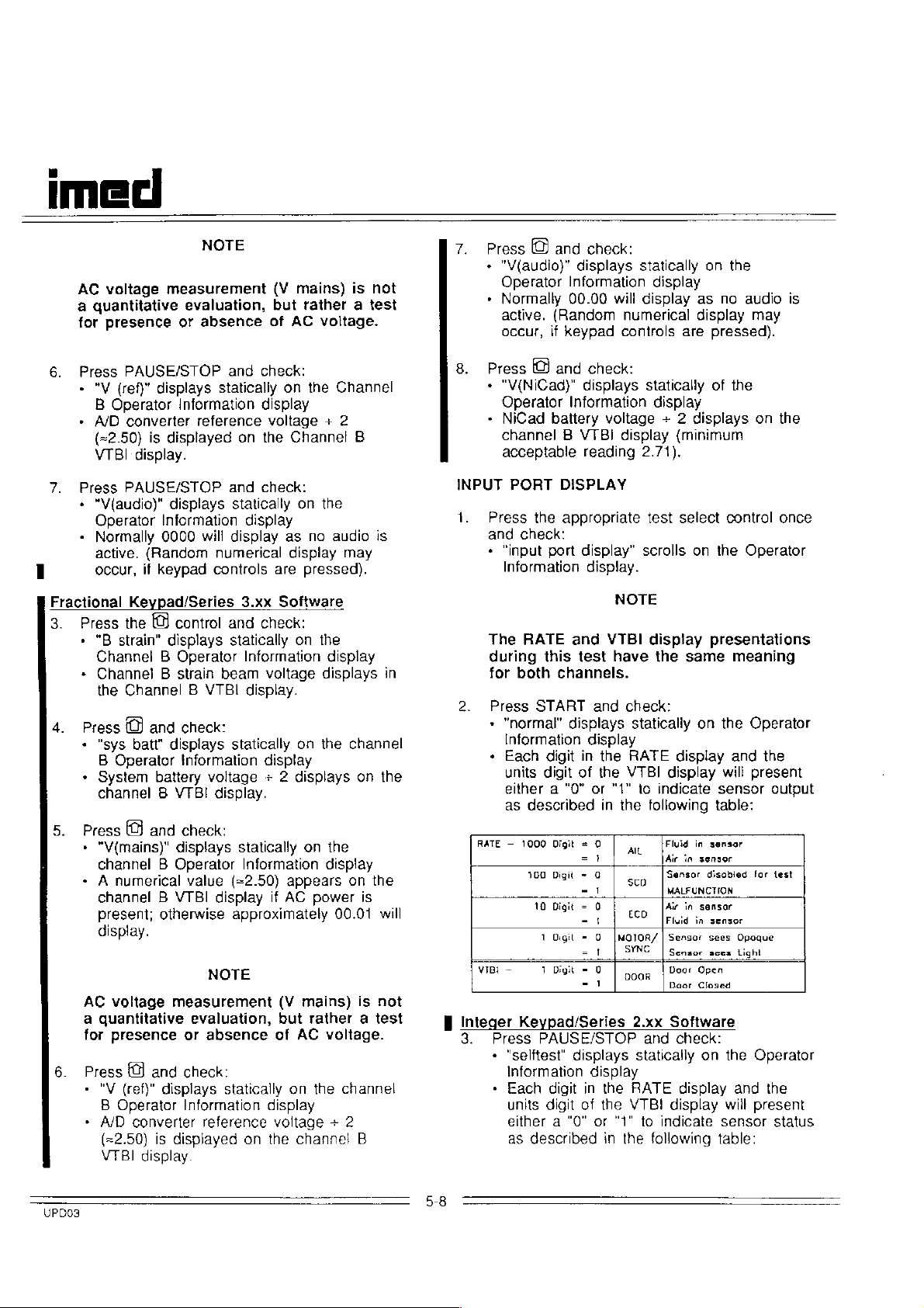
1.
2.
RATE — 1000
γι
B
integer
3.
PORT
Press
the
and
check:
»
“input
Information
The
RATE
during
for
Press
»
+
BI
this
both
START
"normal"
Information
Each
units
digit
either a "0"
as
described
100
10
1
- git
3
Keypad/Series
Press
+
+
PAUSE/STOP
"selftest"
Information
Each
units
either a "0"
as
described
DISPLAY
appropriate
port
display”
display.
test
scrolls
NOTE
and
VTBI
display
test
have
the
channels.
and
check:
displays
digit
in
of
Digit = 0 | 。
=}
Digit = G
=1
Digit = 0
-3
Ogit
= O
=1
=
Digit = 0 | ga | Door
=
displays
digit
in
digit
of
statically
display
the
RATE
the
VTBI
or
"1"
to
in
the
sco
Eo
|MOTOR/ | Sensor
SYNC | Sensor
2.xx
statically
display
the
RATE
the
VTBI
or
"1"
to
in
the
display
display
indicate
following
[Fluid
Air
Sensor
MALFUNCTION
Air
Fluid
Daor
Software
and
check:
display
indicate
following
select control
on the
Operator
presentations
same
on
meaning
the
Operator
and
will
present
sensor
the
table:
in
sensor
in
sensor
disobied
in
sensor
.
in
Open
Closed
on
display and
sensor
sees
Opoque
sces
tight
the
will
sensor
table:
for
Operator
the
present
once
output
lest
status
UPDO3
5-8
Page 9
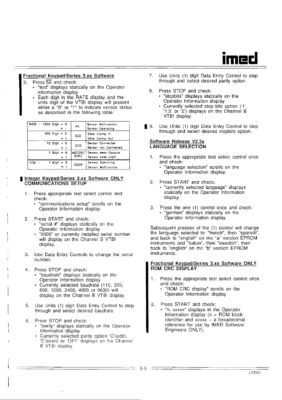
Fractional
3.
Press © and
*
*
RATE - 1000
VTBI — Y
E
Integer
COMMUNICATIONS
1.
2.
3.
4.
Keypad/Series
"test"
displays
information
Each
digit
units
digit
either a "0"
as
described
Digit
100
Digit - 0
10
Digit
Y
Digit = O
digit - 0 | ooog | Sensor
Keypad/Series
Press
appropriate
check:
*
"communications
Operator
Press
START
-
“serial
Operator
+
"0000"
will
display.
Use
number.
Press
*
"baudrate"
Operator
+
Currently
600,
display
#"
or
display
Data
STOP
1200,
Entry
on
3.xx
Software
check:
statically
on
the
Operator
display
in
the
RATE
of
the
VTBI
or
"1"
in
the
= 0
=
Information
displays
Information
дк
seo. | Slide
-1
= 0
-4
=!
currently
eco | Sensor
|MOTOR/|
SYNC | Sensor
1
SETUP
test
and
check:
on
the
Controls
and
check:
displays
Information
selected
2400,
the
Channel B VTBI
display
display
to
indicate
following
[Sensor
Sensor
Slide
Sensor
Sensor
Sansor
2.xx
Software
select
setup"
display.
statically
display
installed
Channel B VTBI
to
statically
display
baudrate
4800
sensor
table:
МоНипейол
Operating
Clamp
Clamp
Connected
nol
sees
sees
Opercting
Malfunction
control
scrolls
on
serial
change
on
(110, 300,
or
9600)
will
and
present
In
Out
Connected
Opaque
Light
ONLY
and
on
the
the
number
the
the
will
display.
the
status
serial
7.
Use
Units
through
8.
Press
+
"stopbits”
Operator
»
Currently
‘1.5’
VTBI
9.
Use
Units
through
Software
Release
LANGUAGE
1.
Press
check:
and
*
"language
Operator
2.
Press
*
"currently
statically
display.
3.
Press
+
"german"
Operator
Subsequent
the
language
and
back
instruments
back
to
"english"
instruments.
Fractional
ROM
CRC
1.
Press
and
check:
+
"ROM
Operator
(1)
digit
and
select
STOP
and
check:
displays
Information
selected
ог
'2")
displays
display.
(1)
digit
and
select
V2.3x
SELECTION
the
appropriate
selection"
Information
START
the
and
selected
on
the
one
(1)
displays
Information
presses
of
selected
to
"english"
and
on
"italian",
on
the
Keypad/Series
DISPLAY
the
appropriate
CRC
display”
Information
Data
Entry
desired
statically
display
stop
bits
on
the
Data
Entry
desired
test
scrolis
display.
check:
language"
Operator
control
statically
display.
the
(1)
to:
"french",
the
"a"
then
"b"
version
3.xx
test
scrolls
display.
imed
Control
parity
on
option
Channel
Control
stopbits
select control
on
Information
once
on
control
then
version
"swedish",
Software
select
on the
to
option.
the
(‘1',
B
to
option.
the
displays
and
check:
the
will
change
"spanish",
EPROM
then
EPROM
ONLY
control
step
step
once
once
2.
Press
5.
Use
Units
(1)
digit
Data
Entry
Control
through
6.
Press
*
*
and
STOP
"parity"
information
Currently
'E'(even)
B
VTBI
displays
selected
or
display.
select
and
check:
display
‘OFF’
desired
statically
baudrate.
parity
option
displays
on
the
on
to
Operator
'O'(odd),
the
Channel
step
START
«
"m
xxxxx"
information
identifier
reference
Engineers
and
displays
display
and
xxxxx
for
use
ONLY).
check:
in
the
(n = ROM
= a
by
IMED
Operator
block
hexadecimal
Software
40003
Page 10
imeci
POWERDOWN
1.
Press
the
and
check:
*
"powerdown
Information
2.
Press
START
+
"POWER"
across
Information
seconds
[v3.xx])
+
One
shuts
The
maintenance
prior
to
service
TEST
appropriate
test”
test
select control
scrolls
display.
and
check:
"OFF
n"
displays
the
channel A and B Operator
displays
('n'
counts
from 5 to 1 [v2.xx]
second
down.
aíter
'n' = 1
WARNING
plug
must
returning
for
patient
the
instrument
care.
on
the
statically
or 3 to
the
instrument
be
once
Operator
down
in
1
removed
to
5.4
TROUBLESHOOTING
The
troubleshooting
Table
5-1
are
maintenance
section
procedure
test
that
if a control
Keypad
Lamp
test;
check
The
order
the
corrective
of
corrective
should
the
instrument
If
the
test
repair a microprocessor
your
facility,
returned
mode
5.3.
The
is
to
replicates
key
test;
if a LED
if
the
probable
failure
actions
reduce
equipment
it
to
the
routines
correlated
test
recommended
perform
the
is
not
instrument
causes
actions
probability.
in
repair
to
patient
is
recommended
factory
presented
directly
sequence
the
reported
functioning - run the
segment
are
the
sequence
time
care
required
system
for
to
described
troubleshooting
Maintenance
discrepancy;
is
out - run
fails
to
under
Initialization.
listed
in a descending
Performing
and
expedite
service.
to
troubleshoot
is
the
repair.
the
power-up
provided
not
instrument
in
the
in
Mode
e.g.
the
-
the
returning
and
available
at
be
UPDO3
5-10
Page 11
imed
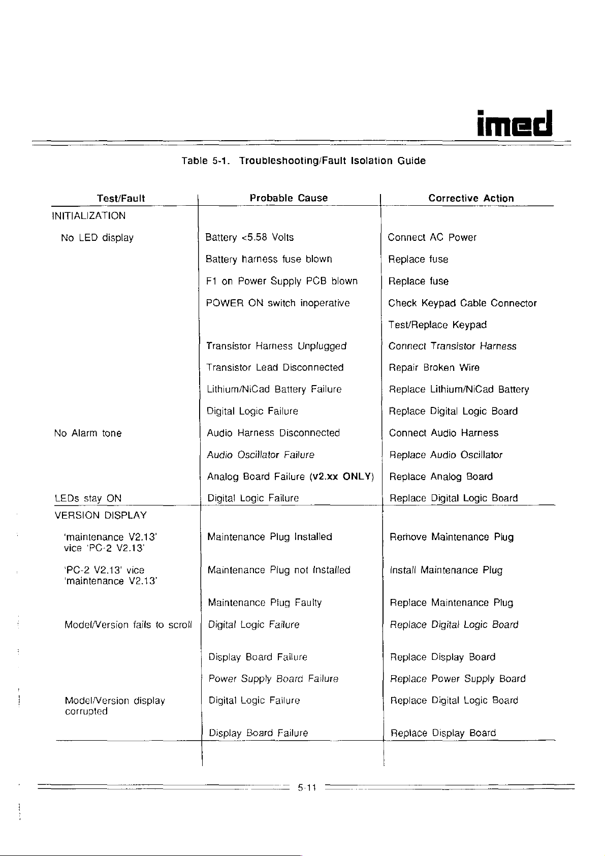
Table
5-1.
Troubleshooting/Fault
Isolation
Guide
LED
Alarm
Test/Fault
display
tone
INITIALIZATION
No
No
Probable
Battery
Battery
F1
POWER
Transistor
Transistor
Lithium/NiCad
Digital
Audio
Audio
Analog
<5.58
harness
on
Power
ON
Logic
Harness
Oscillator
Board
Harness
Lead
Cause
Volts
fuse
blown
Supply
switch
Battery
Failure
Failure
PCB
inoperative
Unplugged
Disconnected
Failure
Disconnected
Failure
(v2.xx
blown
ONLY)
Corrective
Connect
Replace
Replace
Check
Test/Replace
Connect
Repair
Replace
Replace
Connect
Replace
Replace
AC
fuse
fuse
Keypad
Transistor
Broken
Lithium/NiCad
Digital
Audio
Audio
Analog
Action
Power
Cable
Keypad
Harness
Wire
Logic
Harness
Oscillator
Board
Connector
Battery
Board
LEDs
VERSION
‘maintenance
vice
'PC-2
‘maintenance
Model/Version
Model/Version
corrupted
stay
'PC-2
V2.13'
ON
DISPLAY
V2.13'
V2.13'
vice
V2.13°
fails
display
to
scroll
Digital
Maintenance
Maintenance
Maintenance
Digital
Display
Power
Digital
Display
Logic
Logic
Board
Supply
Logic
Board
Failure
Plug
Plug
Piug
Failure
Failure
Installed
not
Faulty
Failure
Board
Failure
—
5-11
Installed
Failure
Replace
Remove
install
Replace
Replace
Replace
Replace
Replace
Replace
Digital
Maintenance
Maintenance
Maintenance
Digital
Display
Power
Digital
Display
Logic
Logic
Supply
Logic
一
Board
Plug
Plug
Plug
Board
Board
Board
Board
Board
Page 12
imed
TIMEBASE
Test
sequence
CHECK
fails
to
step
Comm.
Harness
Disconnected
Reconnect
Comm.
Harness
Test
Test
displays
‘failed’
No
test
LAMP
TEST
LED
illuminate
No
Audio
KEYPAD
fails
to
display
segment
adjust
TEST
start
=2',
w/AUDIO
fails
&
to
ACCESS
Digital
Keypad
Keypad
Digital
Crystal
Digital
Display
Display
Digital
Audio
Switch
Logic
Failure
Failure
Interface
Logic
Failure
and
Oscillator
Logic
Failure
Board
Board
Logic
Failure
Control
Failure
Failure
Failure
Failure
Switch
out
of
Failure
sync.
Replace
Replace
Test/Replace
Replace
Replace
Replace
Replace
Replace
Replace
Replace
Replace
ACCESS
Digital
Display
Digital
Digital
Digital
Display
Display
Digital
Audio
switch
Logic
Keypad
Board
Logic
Logic
Logic
Board
Board
Logic
Control
Board
Board
Board
Board
Board
Switch
Key/Display
Invalid
ERROR
MOTOR
Motor
Homes
Selected
PUMP
Pump
OCCLUDED-FLUID
Key
LOG
HOMING
Fails
to
TEST
Stops:
Mismatch
DISPLAY
TEST
to
home
other
than
Position
or
(See
SIDE
Decoder
Table
Motor
Digital
Analog
Motion
Disconnected
Motion
Digital
Transducer
Transducer
Failure
5-2
for a listing
Harness
Logic
Board
Sensor
Sensor
Logic
and
Disconnected
Failure
Failure
Harness
Failure
Failure
Harness
Failure
description
(v2.xx
Disconnected
ONLY)
Replace
of
Error
Reconnect
Replace
Replace
Reconnect
Replace
Replace
Replace
Transducer
Digital
Log
Codes)
Digital
Analog
Motion
Digital
Transducer
Logic
Motor
Logic
Motion
Logic
Harness
Board
Harness
Board
Board
Sensor
Sensor
Board
Harness
Reconnect
Page 13
u
imeci
HELP
HELP
SERIAL
RATE
ACCURACY
INTERNAL
PORT
TEST
ERROR
Digital
Analog
Motion
Motion
Motor
Stepper
Analog
Logic
Board
Sensor
Disconnected
Sensor
Harness
Motor
Digital
AIL/SCD-Door
AIL/SCD
Door
Digital
Logic
Board
Disconnected
Sensor
Sensor
Logic
Board
Failure
Failure
Harness
Failure
Disconnected
Failure
Board
Board
Failure
Failure
Sensor
Failure
Failure
Failure
(v2.xx
(v2.xx
Harness
ONLY)
ONLY)
Replace
Replace
Reconnect
Replace
Reconnect
Replace
Replace
Replace
Reconnect
Replace
Replace
Replace
Digital
Analog
Logic
Motion
Motion
Stepper
Digital
Analog
AIL/SCD
Door
Digital
Sensor
Motor
Logic
AIVSCD-Door
Sensor
Logic
Board
Board
Sensor
Harness
Motor
Board
Sensor
Harness
Board
Harness
Board
"echo"
AID
|
i
"А
>'0’,
"A
<1.0
pumping
test
fail
VOLTAGE
or B strain"
set
or B strain"
or
DISPLAY
not
installed
>2.0
segment
reading
reading
with
dy
installed
Faulty
Digital
Power
Analog
Strain
Strain
Digital
Analog
Strain
Strain
Analog
Communication
Logic
Supply
Beam
Beam
Logic
Beam
Beam
Digital
Logic
Board
Board
Board
Board
Board
Failure
Out
of
Failure
Board
Failure
Out
of
Failure
Board
Failure
Plug
Failure
Failure
(v2.xx
Calibration
Failure
(v2.xx
Calibration
Failure
(v2.xx
ONLY)
ONLY)
ONLY)
Replace
Replace
Replace
Replace
Recalibrate
Section
Replace
Replace
Replace
Replace
Recalibrate
Replace
Replace
Comm
Digital
Power
Analog
Strain
5.7)
Strain
Digital
Analog
Strain
Strain
Digital
Analog
Emulator
Logic
Board
Supply
Board
Beam
Beam
Logic
Board
Board
Beam
Beam
Logic
Board
Board
Plug
Board
(see
Page 14

imeci
"sys
batt"
or
>'3.55*
reading
<'2.79'
Power
Supply
Board
Failure
Check
fuse
Battery
Voltage
at
in-line
"V(mains)
ог
>'2.55'
"V(ref)"
+.02
INPUT
PORT
Normal
AIL
Sensor - wrong
for
condition
reading
other
TEST
mode
than
<2.45'
‘2.49’
digit
Digital
Battery
Wrong
Power
Digital
Power
Digital
Ultrasonic
Analog
Digital
Logic
Board
Failure
Battery
Supply
Logic
Board
Supply
Logic
Board
Emitter/Receiver
Circuit
Logic
Board
Failure
Installed
Board
Board
Failure
Failure
Failure
Failure
Failure
Failure
NOTE
failure
Replace
Replace
Replace
Install
Replace
Replace
Replace
Replace
Replace
Replace
Replace
Power
Digital
Battery
|.P.B.
Power
Digital
Power
Digital
AIL/SCD
AIL/SCD
Digital
Listed
Supply
Logic
Battery
Supply
Logic
Supply
Logic
Assembly
PC
Logic
Board
Board
Board
Board
Board
Board
Board
Board
The
logic
Normal
than
the
SCD
for
ECD
for
Motion
for
mode
sensor
Selftest
Sensor - wrong
condition
Sensor - wrong
condition
Sensor - wrong
condition
for
the
test
operation.
mode.
SCD
the
sensor
SCD
The
digit
digit
digit
is
reversed
sensor
following
Light
Analog
Digital
Light
Communication
Power
Digital
Sensor
Digital
is
being
SCD
Emitter/Receiver
Circuit
Logic
Emitter/Receiver
Supply
Logic
Failure
Logic
in
relation
tested
sensor
Failure
Failure
Cable
Board
Board
Board
to
for
operation
failure
Failure
Failure
Failure
Failure
Failure
the
other
response
test
sensors.
to
the
processor
is
the
response
Replace
Replace
Replace
Replace
Reconnect
Communication
Replace
Replace
Replace
Replace
AIL/SCD
AIL/SCD
Digital
ECD
Power
Digital
Sensor
Digital
Consequently,
strobe
expected
Assembly
PC
Board
Logic
Board
or
Replace
Cable
Supply
Logic
Logic
Board
Board
Board
in
the
rather
from
Page 15

Door
for
condition
In
the
protocol.
response
strabe
POWER
Sensor - wrong
Selftest
The
to
mode
digital
the
strobe.
circuitry.
DOWN
TEST
digit
the
Sensor
Digital
microprocessor
presentation
If
the
response
Failure
Logic
seen
Board
is
in
is
the
Failure
NOTE
strobing
RATE
not
the
the
sensors
and
VTBI
expected
Replace
Replace
in
displays
response a problem
Sensor
Digital
accordance
reflect the
imed
Logic
Board
with a software
sensors
exists
within
the
Displays
remain
On
Digital
Logic
Board
Failure
Replace
Digital
Logic
Board
=
5-15
Page 16

alemyos
XXA
ci
esne9
91420014
gın
pjeog
91607
Bujueew
이
бо!
607
ола
10413
luapls9JJo
841
dnpels
sso]
Buunp
ul
04110581
Åjuo
sJn99O
19584
Sgl9S/DedAayl
』9B9jUl
2-Od
SepoD
Bo7
10113
‘5-6
эает
uond¡19seq
ane
03SN
607
LON
10113
aunyey
:09A
ABYEG
Ave
ane]
QVOIN
le
95ellonA
nono
-
A027
40842
Auayeg
HI
“SaHlue
ane;
pagog
21607
luaumlsul
umop
*ULIETE
suamod
:dn-Jewmod
InOHLIAW
Pue
2945
Buunp
Alalelpsuuuul
Эно
pal5a130
$1
824
WOH
(1#
00003
10113
995)
unie
ange,
nono
pieog
ÁlSgeg
91507
|
uoisnui
gJnIIB
jo
uonod
paissales
‘SIIe}
ey
189]
AISNOIASIT
“dn-s2Mod
949
E
ol
Jo
Buunp
paloalqns
SSOJ
U!
pajosjea
S]INS84
NYH
BY
cA
эзвэюн
эле
элемцоб
ИУНАМ
9/n|1ey
pleog
아
007
οἱ
이
payejai
Sul
1581
*Aejdsip
SlEJjuouunjisul
WYH
jou
syajaweed
SANONUISEP
S1U8ul69S
ynejag
‘siajeweled
aasn
LON
'5JsleuueJgd
VH
E
dn-18mod
UO
DSuJOJ8d
uolsnuut
Buung
gJnlIBd
VH
인
미비
01608
91607
INOHLIM
이
10949
4406
94600
95Bue」
B
046
"dn-JeAod
12840
Аирнел
5uun
“uueje
ロ
で
LC
て
A
(L#
8PO9
10113
969)
аапие;
иполо
Алэдез
|
$591
UI
“siajauesed
D9O1S
зупвел
S』919UJBJBd
UOISTJUI
UO
9SB919H
9』BAJOS
'pakeıdsıp
хоецо
UOISTyUI
SIL
ae
payoajas
JO
9JnHEB
Apsnoiaeid
ゴ
D9uJJOJ9d
WVHAN
JO
"Ans
Y
EE
ZA
9S6SI9H
52949
ÂNUEŞ
элемцо$
idwayy
‘pebeyosip
94004
Ajanisseoxa
+
10)
95JBUO9』
Layeg
имор
asned
‘paysayo
1эмо4
JCA
Аэуерашиш!
0€'S>
s|
aBeyoa
40
suajawesed
ynejaq
jo
Ino
Siajawesed
[BONO
Q'8<
‘dn-samod
O1
Siueuu9JnSBaul
1U9UHTJISUI
Buying
SU]
인
미티
30461
시
9469
(14
ap00
1003
99$)
эллие}
ane)
иполо
preog
Álspeg
91607
UueIY
LNOHLIM
XINO
εἰ
ane;
6
элпие;
958Ε8ΙΘΗ
peog
рлеов
DIEMYOS
BoleuY
91607
10
49945
Аэцеа
Чп-лэмоЧ
биипр
$11590
пизи
jo
0
uohelduuoo
Ol
y
uy
“UoISISAUCO
q/y
antes
GAY
841
99062
яцрзоэуэр
uodn
[^
MOPUIM
pouuuueJ6oJjd
с}
ssnie4
luanbasqns
Aue
99STİ
‘sbuipeai
09
si
1dnJJ81Ul
E
UYUM
DAY
:0}
1U8UHTM1SUI
‘ON
9P09
00
LO
20
£0
#0
5-16
SO
90
£0
Page 17

品
21
59003
ame,
элпив;
pieog
реоа
Áeidsiq
91607
„HOHYJ
SI
ui
yey)
paniadas
si
epooksy
Ἴ81Λ
ΡΗΕ
2
UOYM
ojeH
$21990
Sul
uy
‘abuel
IVNEJLNÍ
apooday
JT3H.
|e6al
'PoBGoj
SU}
jo
apisino
Si
10183
pañeldsip
"dnG
цве
DUP
2p09
LNOHLIM
CE
ELZA
эзеэ1эн
dIEMHOS
10118
て
A
0Stojey
SU]
UAODP
UM
dIEMHOS
J9Aod
dn
490]
apookey
geodde
ulB
‘ON
peubisseun
内
SABIdSIP
8P09
1013
au}
DUB
pallo49S
의
‘pueog
1A
UE
SeA12981
PUB
ABIdSI
コ
1VH
10859901
SU)
9U]
LOL)
Ul
Kay
pre
aul
aasn
LON
80
11-60
ALON
10443
101
1994104
2p09
pjeog
10112
91607
ou}
Áejdsip
ATNO
IM
yuenbesans
DUB
OE'ZA
9589191
э4емцоз
SILUEIJ6oud
JO
YO9UO
suhnol
AEMEUN
140,
e
©
MOUS
6uunp
B
UBUM
[IM
paloalep
S1NDD0
Åejdsip
ojeH
SIBMYOS
041
'4810510
10113
WA
QIBM}OS
painSyuos
1817.
041
[PJ9UDD)
비
S1U83UJr1J1SUi
66
46004
el
peIIOJoS
SECA
YÖNOYI
SI
YOUNS
ÇE'ZA
TYØNHILNI!
asSeal3H
DIEMYOS
d
13H«
“oil6ol
eu)
ul
sieadde
'SABIdSID
‘on
apoo
IdB1A
103
PUE
94]
ヨ
1VH
pue
人
]NO
9Jnllej
EL
と
USIuBU99W
BuldUund
эапие;
A
956919Н
реоа
э4лемцо$
баечу
JO
„HOUHA
ajdwies
e
ui
%G'|<
1018
UB
USYM
Y
"YO
sieadde
gu1
Aq
“ON
TVNH
D9129j8D
9p09
ヨ
1NI
10113
SI
1
SUOIInIOASj
ヨ
9041
H。
0SUSS
2046
0
」O19UJ
히
el
OHOUU
09
10105
SI
$11550
HO
DUAS
J010N
“sAeldsip
IgLA
PUB
ALYH
041
녀
人
INO
9JnllE」
&SrzA
dusluguoeW
_6uldtund
ane)
3aSeelaH
Pieog
SJEMNOS
Bojeuy
Jo
„HOH4I
ajdujes
€
Ul
%G'1<
10149
UB
UDUM
&
‘U9
sapadde
341
0
‘ом
IVNHILNI
00129190
8p09
1013
SI
07311,
SUONN|OAA
'709499
JOJO
SINIIO
40404
OG
HO
AUAS
1010
Pi
3U
PUR
P3||OJ0S
SI
ainllej
usSIuedosm
인
미티
07609
6uldund
91607
841
0cL
JolOU
10
S19918D
9AlJBJ9dOU!
UUJUUGO
』OSUSS
“SAeldsip
O1
SI
UONOLW
』OSU9S
9JnIIB」
1381
J91JB
91}
Pu
ヨ
1VH
841
ul
UOI1OUJ
USUM
Sd81S
9U1
SINDIO
JO10UM
"9UAS
Y
“yo
pejoajap
6elj
9uAS
ON
gi
NINO
Е
[СЛ
ane
9569195
peog
э1емцо$
Воецу
ay)
pue
DUE
ЗЕУН
5110195
eu
,HOHH3
ul
siesdde
"Bulu」n1
1IVNUIINI
ON
'SABIdSIP
1OU
8DOO
SI
dIIH.
JOQ1OUU
JO』
[1」A
ヨ
5-17
Page 18
ci
80161
01608
91607
ATNO
인
ELFCA
미비
wsiueysay
9SBel9H
SIEMYOS
Buidund
ane)
plgod
Bolguy
paysıuluıg
AnoJlO
Ayoedeg
」95JeuO
4ΙΘΗΕΒ
Asayeg
pieog
AddnS
9A0d
ane]
Åjgquossy
элпие;
sseuseH
рвов
5607
1000
einlel
AIqulessY
gunpie;
SSAUIEH
piueog
21607
4000
SS9UIBH
gine)
pieog
J0O0Q/IV
IV
94/18]
espe)
pieog
91607
GINE)
pieog
IV
eJnlle}
элпие;
SSauUeEH
рлеоя
1001/ΙΙΝ
91607
eunpe;
pieog
Aiddng
Jamod
su
021
10104
10
5199199
VNd
9AIHEJ9doUI
ヨ
14409
JNI
JOSUIS
d]
이
SI
J0SU9S
한미!
49116
@H1
UOHOUJ
U9UA
sd91S
841
SJn29O
Jolouu
“OUAS
ヨ
H,
"UiuJn
UOIIOuJ
‘ON
8P09
1013
SI
PUB
SIIOJ9S
10U
HOHH
SL
JO10U
ヨ
uo
'SAeldsip
uorHBiado
19LA
SNONUHUOD
pue
コ
」yd
jo
SINOU
9ul
ии
BLZ
SJBeddg
199
Aaneg
2
10)
dje19do
1SEJ
e
JSTMU
'algeun
JUBLUTUJSUI
)1
!
시
3160
Uamad
40
54004
Jy
ge
JEBIB
‘рэббо|
d13H.
OpnB
зе
88
"SIIOJOS
$
в1
HOHH
зароо
0400
ヨ
1018
1VNH
86164051
‘SpUNOS
ヨ
1NI
ㅁ
已
Sioalep
TSH,
JOSS990JdOJOIU』
“sdojs
Burduind
‘igs
A
ul
she|dsip
1051195
JOOP
9U1
USuAA
ay}
JO
Sn99O
Bune}
70013
041
008
910198
„НОНЫЗ
ПУМЫЗ1м
B
Ι81Λ
S199)SD
ρυ8
31Η
oy
UI
suzadde
“ON
“SABIdSIP
BpoD
10113
IQLA
94)
PUR
алЗнН.
」OSS920JdOJOILJ
PUE
giy
SIO19S
‘10SU9S
ou
ul
,HOHUT
sigadde
100p
9U1
U8UW
941
TYNHALNI
‘ON
JO
SJn99O
9TIIBj
эроЭ
TVNH
6
5108190
105580010010!041
041
1494
‘sfejdsip
‘ON
ヨ
1NI
8p09
d]1
1043
ヨ
H,
J0SUSS
SU)
DUE
]IV
$19.98
Sul
„НОНЫЗ
Jo
SINDIO
히
미
비
“skeldsıp
[ALA
PUB
JLYH
au
ui
sieedde
TVNH
ゃ
s12819D
』OSS99OJdOJOtUJ
9u1
USLUA
"ON
ヨ
1NI
9POO
d]
JOJ
ヨ
H,
ヨ
JOSUS@S
9U1
PUB
]IV
SIIOJ9S
au)
„HOHHA
Jo
SJn29O
ane]
-skeldsip
IGLA
PUB
JLVH
9ul
ul
siesdde
ST
SUA
0'8<
95gJOA
ん
gd
USUA
ur
ssgedde
„HOHHJ
1U9UJTU1SU!
"ON
SABidsIP
TVNd
9poo
ヨ
IEUJJOu
1NI
1Qj』』
IdH」A
d1
ヨ
BuJnD
эцурие
コ
PUB
H。
コ
'uoliBJ9do
pajosjop
SJT99O
1VH
$10.95
eu
g
uo
pojoajep
Beij
DUÁS
ON
9}
6y'ZA
aSealebHd
qasn
GIEMUOS
LON
LI
81
eBieuyosig
4ayeg
1824
GISN
LON
61
VHO
uuBIV
9JnIB
1000
02
шлем
элпиез
8
1000
ηὈ
Le
5-18
v
UD
UHEJV
ONE
IV
ce
日
UO
UJBIV
anes
TV
ge
ABJEUDABAO
aasn
ん
491
LON
日
Sete
ge
Page 19

ane}
pi20g
91607
ante;
preog
51607
ainiey
pueog
ai6o7
9npe)
pieog
Aejdsig
elmes
pleog
9107]
ame,
pieog
Áejdsig
“paBıeyosıp
Ajaaisseoxe
aq
Aew
Aaneg
'зллоц
фе
10;
eine;
Алецеа
pueog
облецоэц
Boreuy
элпие;
ane;
риеоа
peog
баецу
91607
cl
ΘΙΠΙΕΙ
ΡΙΡΟΒ
91607
JO
adl
Jo
:aud5
aseqauull
ut
sigadde
.HOHHA
19$
au]
‘ON
TVNH
JO
8P09
9PISInO
ヨ
1NI
10113
ul
d
AU)
Joss9ooJdoJoluu
USYM
SINDIO
841
pue
99uEJ9101
SilloJoS
Iu9uumisSul
JO9UO
„HOHHI
OH
IeuuJou
TVNd
au}
"sÅejdsip
JO
ヨ
6uunp
1NI
9JnIIBJ
Ι8ΙΛΡυΕ
9124
au}
1
peloalap
ヨ
U9UA
H。
'uonelado
SI
SJn29O
NOH
|
UOISNJUI
ur
syeadde
WYH
95ur-jO-InO
JO
‘ON
'SABIOSID
49349
эроо
UB
36461
』0』』
IBTA
PUB
318
94}
6484
$11590
SIO918D
SJ319UJBJEd
ヨ
9U1
PUB
SIIOJOS
ul
suvadde
。HOHd
ヨ
‘ON
'SABIdSID
TVNH
9DOO
1NI
ヨ
』0J』
IIA
ヨ
KTAH.
9H1
046
DUB
318
'UOHIPUOD
SIIOJOS
041
SIB」
-эшед
JDSS990dOJOIUJ
эищ
раоэаха
9ABIS
эщ
ицим
SU}
UAUM
puodsa
SINIIO
0}
Bopyojem
эц}
изцм
ап-лэмо4
бирпр
$21550
4+,
OB
OL
STĚ)
ХИН
“ON
10]ΒΙΘ4Ο
8209
TVNYEINI
40113
u]0q
PUB
d13H,
SSOI9E
1055990.
иешиаши
SÁRIdSIP
‘9881
SIIOI9S
LOHBUUJOJUJ
097
,HOHH
ULIM
引
ABIdSID
'Sheldsip
JOSSADOICOIOI
Iuaul59S-/
19LA
PUE
B
SAB|S
UIU1IAA
FLY
SU]
9JTIIB」
Ou)
UBUM
ul
B
sIBadde
Si9919D
SINDDO
HBnoJu1
TVNdH
Λα
“ON
ヨ
8P09
©
1NI
peal
JOssg2oJd
1013
d1
o}
ヨ
aiqeun
H。
9697+
s|
UIYUM
‘jauueyd
99U919)9』
SJT99O
алу
ие
EU}
DUE
siloJos
,HOHM
引
UIBUJ
9H1
USUA
-SABIdsID
0}
19UUBHO
$18}
105589029
IHLA
DUE
コ
1VH
au}
ul
sipadde
али
ие
чо
иеш
дг`о
эц}
15Ε8Ι
чецм
18
$40950
19818P
d3H,
10113
BLA
9u1
pue
“UONBANDE
DUB
3.
vu
SIIOJOS
eu)
Ana
ul
HOHdH
sieadde
oipne
ヨ
TVNH
'ON
ヨ
1N1
2P09
-sápjdsip
ButMOIO}
BINIE4
YOBYD
JDU
L
Le
amied
080
WOY
ge
AIUBSUJ
606
INS
号
58'ZA
EE
GA
asSeal9H
9589104
qasn
BIBMYOS
SIPMHOS
LON
0€
1nol
элпиез
uuuoo
боруем
9AB1S
LE
"Ans
る
EC'
EL
て
ZA
A
85898Ι9Η
6888ΙΘΗ
aasn
ze
LON
91ΕΛΜΟΣ
d1PMHOS
eines
juawbas
ΘΙΠΙΘ
aasn
9ABIS
LON
18Η
A
YELE
GE
gine
орпу
9€
5-19
Page 20

cl
jdweny
'pabieyosip
9Jnllej
элпне;
ame,
preog
Áe¡dsig
“sinoy
Ajaaissaoxe
у
10;
аблецовл
人
Au8B
pJgod
Аэцеа
рюу
pes
AIddnS
J9Aod
e
JO
panodas
SIEMPIEY
sey
JOYYS
JosseooJd
‘10139
Áejdsig
Bulssadod
ΘΙΕΝΜΟΞ
9UL
E
Spral
d'13H.
JA
UBAUOO
“Ars
Mojaq
(/Y
*SH0s9S
UE
эбенол
USUM
,AWALIVE
311990
Аецед
EL
cA
SSB9ISH
03SN
OIPMHOS
LON
“ONS
9
EE
て
SMIEIS
A
9SB919H
BARIS
9JBAJOS
PEA
"ans
%
5Б°СЛ
で
EL'ZA
9SBgISH
5529194
Q
ヨ
Sn
ΘΙΕΝΗΟΞ
1ON
э1емцо5
4013
|}
LeNeg
MOT
элпие;
Аэнеа
ploy-pea7
E
алэн.
SDE8」
‘зиол
』9J8AUOO
$$
моза
али
ие
эбецол
игум
3419550
Аледед
人
]NO
SL'
10413
て
A
9SB9I9H
п
Аэцеа
gasn
9』BAHOS
MOT
LON
ane;
pjeog
AddnS
samod
`
944840
위
4100
990126
5]|0125
,
ㅅ
4143
178
SE
C/CE'CA
OSPOJON
CISN
DIEMYOS
LON
UAOP-J9Aod
Aeneg
Pieoa
J9doJduul
MVHAN
91507
зиэшпдец!
WYHAN
Ppeuoyped
jo
чошиед
601
1043
6P'ZA
5SBaleHd
9JBAJOS
Hnejap
ul
sajqeve,
usaMaeq
о}
'рэббо|
региеши!
“dn-18mod
9Jnllej
DHO
B
paouanadxa
SOJQEUEA
WYHAN
007
1043
1
эроо
эле
pue
uonued
ло
umop-samod
рие
pajoaye
запел
э.пие;
Азцея
рюу-реэт
|
$еч
иоуриоо
п
Азэцеа
мол
E
USUM
`
4650
히
$11990
si
ELZA
9SB9ISH
3JBAJOS
ane}
pseog
Ajddng
Jamog
pa6f60
имор
si
*UIETE
10119
лемо4
JENSIA
UY
зиэшпдзи!
‘запиш
10
OIPNE
€
Аа
LNOHLIM
10}
рэмоно
Paysixe
SEZ/EEZA
40113
эзеен
И
Аэцеа
CISN
элемцо$
LON
MOT
UMOP-19M0g
Aeueg
pieog
JedoJdu]
NVHAN
21807
υΘΘΛΑΙΘᾳ
pauoryed
θ1ΠΙ8/
Jo
uolyued
989
B
p9ou9u9dx9
dnjeS
uosiol
VHAN
Paxiy
INVUAN
6P'ZA
dmes
o5PajoH
1981018
ölemyos
PExI4
juauurusu]
Mnelap
ui
selgeuga
0)
"peB6ol
pazieiu!
'dn-Jamod
s|
8PO9
sue
uoNped
pur
10419
umop-s9mod
PUR
pajoaye
SONIBA
ΞΘΙ4ΞΗΕΛ
UAOD-J9AOd
』900JdUU1
pauoiuued
Jo
uogued
EJEG
IB9IHO-UON
"ejqesn
St
65
ζΛ
9ΞΕΘΙΘΗ
CISN
ΘΙΕΝΠΟΞ
LON
Ásneg
pueog
WYHAN
21607
49600
эллие;
Эно
8
D99u9U9dx9
WYHAN
VHAN
PIE
ΙΕΟΠΗΟ:ΗΟΝ
шэшидзи!
упе;эр
Ul
S9IdPUBA
оу
'рэббое
рэзнеи!
"dn-J9AOOd
$}
эроо
эле
DuP
иошие4
10118
UAOD-J9AOd
pue
`
раэде
4650
히
Sonja
SI
зааенел
ロコ
ST1
ION
LE
86
6€
0+
5-20
Lt
cy
er
ty
Page 21

ci
pueog
91607
umop-18M04
ΑΙΘΗΕΕ
18do1duut
ΑΝΗΛΝ
pueog
91607
aunyey
힌
미티
weag
01609
UCS
21607
aunie;
90018)
шеэд
pieog
LIENS
91607
имор-лэмоа
ん
ed
48d0Jduu]
WVHAN
VHAN
ugamıag
DuouJed
9JnIIBj
jO
uolUed
OHO
911S
189149
]USUJru1Sul
Inejap
ul
SajqeueA
0}
'P95Bol
pazigeniui
‘dn-Jemod
S!
gPO9
sue
pue
uoniued
P
P99ugu9dxg
J0JJ9
umop-Jamod
PUE
“BIgesn
pai0oye
S9nIBA
si
WYHAN
uggAl9d
pouolpyued
unIE」
jo
uoniued
PIG
JEDNI
шашпдзч|
упеуэр
UI
зааемел
о}
‘рэббо|
рэтиеши!
'ап-лэмод
$1
эроо
эле
HO
рие
чошиеЯ
E
D99uSJSdxg
2018
имор-лэмоЯ
рые
"ejgesn
раоаце
запел
st
U32MI9Q
104
s9op
ueyel
SDUBLEA
Joss99oJdoJotuu
aul
|O
Лш
001
1583]
usuA
Je
ποσο
19919p
Joiouu
S6ulpeal
9ui
1Sawol
Jo
suolinloA9Jz
pue
1594614
Buunp
DU)
U199M/9Q
10и
S90p
SQUBLIBA
10$5a901d01IUI
JO
ALU
001
AY]
1SB9
USYM
"SIUueUoasu
JE
SINIIO
J0818P
Uayel
Jolou
96410681
9ul
159
Jo
SuolinioA9Jz
이
046
“wsIueyoow
1584014
6uunp
Sul
заавиел
VHAN
6D'A
9SB8I9H
91JS
SSIQBUBA
[EONUO,
öJEMYOŞ
бусл
WNVHAN
ээвазн
2120
TENUI
элемцо$
Gb
sy
35Η
ΙΟΝ
Lt
Y
YO
alme
y
Rog
UTES
αν
g
49
une
Wee
UIBJIS
5-21
Page 22

品
85063
alqeqoJd
힌
gjnIB)
미티
eiemuos
XX'£
Souag/pedÁdy
|BUONIEJA
Z-dd
SapO9
507
10413
Buluesy
09116
DIBC
시
01607
9469
$1
Bo]
бо]
Jous
10113
juspisa!
au}
‘dnuezs
jo
ssoj
Buunp
ul
Buynsa!
Амо
"Saus
$11920
18501
ene,
:OOA
Á1ayea
VH
OYOIN
le
aBEYOA
-
AOZ>
MDAUD
I
ane)
preog
obo"
ol
Sl
palelel
Su
1801
WYH
SlHej
104
luauunnsul
aanamisap
SIuatu63s
's49l9uueJed
NVH
e
dn-zamod
uo
psuuuJohasd
uolSnJul
5uunQ
LNOHLIM
umop
sJamod
pue
уэацз
Ауриел
Use
\dwany
‘pebreyosip
Ajeaissaoxe
Álageg
‘рэхоэцо
5!
эВенол
(L#
8p09
1013
886)
amie,
smoy
y
JO)
9612984
UAAOD
esneo
4e/wod
эал
AiaiElpsuuuul
05`5>
10
0'8<
‘dn-1amod
oy
зиешеллвэш
Wuauunnsut
Buung
au
ane]
noo
peog
Áleneg
obo]
‘UUEIE
LNOHLIA
sinpe)
pieog
91607
Q
16
0}
12842
fieyeg
dn-1emod
Buunp
sinaog
이
Y
sine
UV
‘UOISISAUO9
uodn
“sbulpeas
paotuuupJ6oJjd
(J/Y
a/y
Juanbasqns
Jo
uolalduoo
si
idmJ91ul
Áue
29917
:0}
JUBLUTUISU!
G£
E
UIU}IM
Jdnuajul
styj
J9919p
шве
JNOHLIM
で
[る
BY)
A
9SB919H
9STB9
UMOp
им
9』BA1JOS
Jomod
MODUIM
αἱ
pañeldsip
"anS
DUB
ap09
EE'ZA
10148
‘TELA
9SB9I9H
ayı
pue
Yum
dey
dn
9JBAAUOS
3001
ou)
sine)
ange;
pieog
peog
Aeidsig
91607
wiOWYS
91
1041
uy
09
'95ug』
WNYSINI
시
9281
gpOoA9y
SI
8PODÁBY
dTSH.
[eda]
E
‘pa660;
au)
иацм
jo
apisino
5119520
si
10119
apooday
sipedde
UIB
‘ом
pauBISSEUN
'84610910
8P09
10113
1A
UE
S8A6981
041
PUB
046
ヨコ
1VH
0
1055809014
히
10405
94)
ul
의
"PJBod
ABIdSI
9ui
WON
"εσ-ο
948
uonduoseg
CISN
LON
‘ON
00
2P09
UPDO3
sine
607
10113
10
03SN
entes
LON
NvH
£0-20
70
qasn
LON
50
Θ1ΗµΕΙ
ΛΙΘΗΕΒ
90
5-22
ime,
OY
40
Agy|
PIIBAUI
80
Page 23

ci
ange
Wwsiueysay
Buidund
diud
WOH
Peg
ane]
pseog
91607
49869
OH9
'NOY
980
10ἱ
9lunuru
ρθΊΕΙΠΟΙΕΟ
ayy
Jl
5!
“SHUBG
ΘΠΙΕΛ
WOH
OHO
JNO}
SLUHUTU
SU)
49
V
d13H
E
Jo
Pajenojesald
sajÁq
‘peradsns
2
158]
ay)
ay)
si
uondnue?
yojeu
ul
pajo]s
you
amen
WOH
S90D
apo0
4003
“sllolos
HOHH
ヨ
TYNHILNI
JO
шее
SIduJBS
‘0,
&
и!
sdeidsip
%56`1<
ajey
ое
“sdojs
"18.
ие
duind
LA
изум
UI
SAidsip
‘spunos
511990
eu1
Аа
рараер
$!
зиоцполал
2010
05
„HOHUJ
sreadde
‘ом
ΙΥΝΕΞΙΝΙ
‘sheidsip
эроЭ
1013
JA
α
13Η,
LA
adl
PUB
40SU8S
PU
ALVE
DSIIOJOS
UONOU
SU}
Li
SI
aunwey
wsiueyoayy
Burduing
Jo
«HOHHI
ajdwes
e
ul
969'L
で
JOJJ9
ие
иэум
$11590
sieadde
ad
Aq
‘ON
TIVNYILNI
paloslsp
SI
SuollnioAal
10JOW
OS
"SABIHSIP
8P09
1017
Id1A
«13Η.
au}
PUE
199495
PUB
ILVH
DSiIOJOS
UONOW
8U]
UI
SI
ainpey
wsueyoow
힌
미비
00609
Burdung
이
007
UB
Sd8|s
SJO8]9P
JOJOLU
SI
JOSUSS
10SU8S
JO
зашли
uOIOUJ
UOHOUI
9U1
041
AU]
ul
"UOIIn]OA』
UBUM
SS
|<
SINDIO
10118
Jad
au)
pue
pur
“Buluam
ヨ
1VH
sjoJos
eu
JOU
LHOHHAI
ul
SI
sieedde
JOJOW
TVNYSLNI
24]
“oy
эроо
d
13H.
10.3
"sÁejdsip
IdLA
JO
9AIIBJ9doUl
ame,
wisiueyoay
ane;
preog
6uldund
51607
це
$4918
зоэуэр
зоюш
sl
JOSU9S
OSU9S
JO
J901unu
UOI1OLI
UOI1OUJ
BUI
By}
81
Ul
'UOIN|OAS
USUA
%SZL<
511590
Jouve
Jed
gu1
PuB
PUB
Duluunl
3
LVH
SIIO49S
ou
1OU
HOHH
ul
SI
1010144
sipodde
ヨ
IWNYALNI
9U1
"ON
0
BAHBJ9doul
'SAEIdSIP
9POO
d
13H»
1017
IHLA
pieog
AlddnS
Asyeg
Jamod
이
‘UOnipuco
위하
ἆ13Η
\!
44400
511290
|!
'ρθθδοι
Аэнея
941
10111
'64161640
1moy
01
мот
"SINO
е
увм
S'Zz
LOHDUNÍUOD
10]
e
2940
Jaye
yl
915
ge
9
81
Sapoo
Jou3
ydaoxe
dund
‘0,
SI
palqesip
@po9
sAeidsip
1043
cue
ejes
чолиоо
‘palposos
‘IQ
LA
‘doisyasnvd
ие
SI
UI
рие
AHALLVE
paAejdsip
‘$4043
eme
anes
NES
81154
y
OHO
9890
0
|
MUB9
MUBA
AOH
WOH
DHD
OO
©
E
MUBA
1469
WOd
WOH
UD
HO
OUÁS
290
60
o
bh
el
el
8
"49
HO
SUÅS
1010W
yi
v'U0
popejep
Sej
DUÁS
ON
SI
5-23
日
UO
De19elep
6el
9uAS
ON
9Η
ebieyosig
ロ
AISNEg
ヨ
Sr1
LON
1524
8+
ἐν
UPDO3
Page 24

imeci
einlej
pleog
1607
Aaneg
Θ/ΠΙΕΙ/
Ρ1ΕΟΒ
51607
Sì
BPOI
‘dn
JO
10
d13H
samod
9Sn
BOpyojem
jnoullw
"91
UAOD-5J9AOd
"IOJIUO9
dO1S/
1USUJTJISUI
ヨ
STVd
10143
pue
juanbasqns
oms
paBíoj
WA
90
BOHYJ
uO
iM
‘auney
6L
IVNEJLNÍ
9000
Aiayeq
10119
uneje
1,0,
SÅejdsip
912)
TELA
ut
padejdsip
E
S)50]9p
1deoxe
d13H.
Josso29oJdoJoluu
palgesip
8341
'dO1S/
484
ヨ
ST1Vd
SINDIO
‘10$U25
100p
eu]
JO
ΘΙΠΙΙΕΙ
9JE
SIOJIUOS
IE
‘spunos
9JnIIBj
Адшуз$\у
з5ашен
1000
10113
IBLA
041
PUB
046
ヨコ
1VH
SIJOJOS
Sy)
ul
,ΗΟΗΗ3
sieedde
]VNH
“ON
"sÁejdsip
spoo
ヨ
1NI
alnyrey
A\quiassy
siniie;
SSAUJEH
pieog
91607
1000
Β
10113
ΞΩΦΘΙΘΡ
30559901d019IL1
au]
uUdUM
SINDDO
IALA
841
046
d13H,
0468
3198
$10.55
J0SU9S
ou}
ui
。HOHH
злеэдае
JOOP
ヨ
dj
]VNH
‘ом
jo
dne)
spoo
ヨ
1NI
SINE}
SSBUJEH
Bune}
PIEOG
JOOG/TI¥
WV
OIVNHALNÍ
B
SI98J8p
10868901d0/9NL
BU)
USUM
“sApidsip
SINIIO
“sAeldSip
‘ом
эро
13H,
{LA
101173
PUE
105465
эц}
31VH
рые
]IV
5110295
ou]
9u1
ul
„ЗОННЯ
JO
sieadde
SINE)
SINE}
ainyie}
preog
91607
SSOWEH
Θ1Π/ΒΙ
ΡΙΕΟΒ
J00Q/11V
UV
TVNH
е
812919D
JOSS99oJdo2ILH
8H1
9HA
SJn92O
“ON
ヨ
TNI
8PO9
d]H。
10113]
J9SU8S
BU)
PUR
]IV
S]019S
8HL
.HOYHI
JO
9JnIIEJ
'SAeIdSID
IHLA
Pue
JlyH
au)
ui
sieadde
ane}
pI20g
91607
sine;
piueog
Aiddng
smog
ΝΝΗΞΙΝΙ
SI
OQA
luetumisul
0
8<
41Η,
86giloA
“94019
IEuJou
Азцеа
dun
Buunp
чацм
‘uonesado
P919919P
51022
aJnpe)
pieog
0807
"SÁRIdSiP
"ON
eu]
9P09
JO
12042
IGLA
10113
aseqauull
PUB
SU}
ALYY
PUE
By}
stoios
эчу
UUM
и!
„HOHHA
злезаае
SINDIO
ur
sipadde
«HOHHI
199
941
‘ом
ΙΥΝΗΞΙΝΙ
10
ASPISINO
SI
1055890/d0J9LU
‘SAEIdSIP
эро
10113
IALA
41Η,
84}
PUE
PUE
99818101
9]EH
$1095
öU)
UMOP-JaMOJ
Jadorduj
6,
UPDG3
Y
"UD
aan
4
10SU8S
1000
06
日
HO
aunlej
JOSu8S
2004
У
YO
LB
эле
Wy
ce
5-24
9
чо
шем
але
лм
ee
эблецолэло
03611
Азцея
LON
seve
ge
GINPE
4
MOBUO
HALL]
La
9351
LON
6c-8c
Page 25

cl
‘pebreyosip
“sinoy
Ajaaissaoxa
pz
anliel
pleog
Aelds!O
Jo}
Asaneq
aq
Aew
эблецоэн
Aueneg
АлэпЬ
‘sdois
Ul
VNH
D8ABIdSID
е
0]
puodsas
0)
site
105380029
Ава
ヨ
Buiduund
1NI
d]
pue
ヨ
H
‘10858901d
pabGoy
".0,
SÁBIOSIP
st
91607
8p09
9181
10118
au}
Ί81Λ
LOI}
841
“09146910
le
pue
010
0(016/361140
spunos
uujeie
“slloJos
34еохе
HOHHI
зодиоо
yönoluj
TVNHYALNÍ
AGZ
®
peas
9ossaoold
d
O}
13H.
ajqeun
uleuu
"%ST
s|
eui
Ulyjm
‘jauueyo
useuAw
90ua49j91
$11990
Q/Y
UE
aanitej
힌
메티
piBog
01008
91607
91807
-SABIdSID
0}
“ON
318}
8po9
10559904
ISLA
J013
PUB
eU]
шеш
3
PUE
LVH
э\
SIjOJOS
SU
чэцм
ul
,HOHHI
sigadde
$11590
digH,
10143
IGLA
IBUUEYI
ΘΙ/
PUB
‘voneanoe
ΡΙΙΒ
(/Y
UE
LO
AS'O
1Seal
]B
19818P
SLVY
510195
Aginozo
,ΗΟΗΗΞ
cipre
IVNYILNI
Buimolo;
eine;
pueog
Aejdsig
B
payodas
sey
9u1
sossedoud
ul
SJB9ddg
Agdsig
ON
"sÁejdsip
9PoO
gu
idwany
pabreyasip
・SJnou
Ajaaissaoxa
10!
88180091
시
91168
©
зрез.
Jo
элемриец
Jaylia
‘0118
Buissaoo1d
dan.
зэмэлио
“Avis
мова
алу
ие
эбецол
чацм
"SJEMYOS
$11590
Алэцеа
элпте;
Алэцеа
рюу
реэл
"$10155
人
AH
ヨ
11V
ヨ
ane]
pieog
one
Åjddng
preog
Jømod
21807
10
doo]
asempos
une
ul
aouanbes
ÉUNIEO
‘spunos
poÁejdsip
dund
‘paidnioo
s}
xepul
1H9UI91B1S
9960
UUEJE
d]
pue
ヨ
H
"SIOJOS
paBBoj
0。
SABIdSID
HOdH
si
8p09
ヨ
oyel
10118
1VNH
YALA
ヨ
‘sdoys
JNI
U!
(peoejda
WOHJA
JI
EON)
10
949
gJe
B
dO1S/
Suuopod
ヨ
STVd
UONUEĞ
1d89xe
WVHAN
SIOUQQ
“peiqesIp
4263
IIB
Meneg
AYHAN
1snu
oy
uondni09
soud
OHo
anjea
polelnoigo
WYHAN
ayy
saio}s
10
dn
9nleA
pue
J9Aod
yooyo
peJois
'uwoplnus
AypyeAr
uole
山
ane
зиоцезипилиоо
эпе3
g3sn
LON
SAEIS
394
Л
75-16
06
GE
eunlle4
olpnv
95
SMEIS
SAIS
PER
ἐξ
5-25
¡1
시
9468
^
어
86
1013
элемуцосб
jgJeueo
δε
ANYBAN
SalqeUEA
AYHAN
dmieSs
INVHAN
8IEIS
doalole
IBONO-UON
807
paxl
103
09
oP
17
WYHAN
BEC
[ENUD-UON
Er
UPD03
Page 26

cl
umoplamod
элииие;
ге;
шеаа
рлеоя
19d0du|
щедб
91507
Juowngsy
peB5o|
uouued
sl
WYHAN
epoo
'SenleA
“960
』OJ9
9UIO9dS
‘pawinsse
SI
]644100
]Inejep
DP9129JJB
1
ol
이
UI
pazllelltul
40681
S9IQBUBA
4641
9/18
IE
SI
104
sOulpeai
5900
1066800100)
이
41
941
494
511990
Jolou
BOUBIIEA
sd
jsamo|
jo
suonnjoAsi
JO
pue
AU
1S9H5IU
001
z
13881
Buunp
9Ul
16
U98A19d
19919D
ueygl
ane
ane
pirog
weaq
urens
0607
104
SBuipee』
5900
10569301001
이
41
341
494
“Uuslueguoeuu
SJn99O
Jolou
SOUBIBA
эщ
1S9AO|
jo
зиопполал
J9
PUB
ALU
]S9UBIU
001
г
15891
биипр
9
Je
изэмеа
12919D
чауе}
gine;
pieog
91607
yueq
WOH
1514
914)
10U
SI
O
AUBG
“Uslueuoauu
OH
I
Joyesado
seu
s!
10118
epos
U!
SÁEJdSID
19891
Joe
MUBg
ajeudolddy
„JSI
OH
XAOH,
“passados
“paljngoo
‘рэбБо!
ane)
peog
91607
‘uonipuoo
*spunos
Bopyojem
uueje
Ἐ
*Áejdsip
516116
1ΗθΙΠΗ
UOHELUJOJUJ
5Η!
-Jamod
уе
эбеуол
1ndul
】99nDSue41
OIDnV
dund
pue
‘3100$
pa66ol
*,0,,
HOHHA
sÁejdsip
sl
epoo
TVNH
91B」
108
ヨ
1A
1NI
‘syjoa
d1
U!
Z'0>
ヨ
paÁejdsip
H
"Sdons
SI
dn
aje
dO1S/
ヨ
ST1Vd
1d9Qx9
SIQJ1UO9
“paigqesip
[Je
aunpey
ΛΙΘΗΕΕ
pseog
NVHAN
91607
pe66ol
sfejdsip
ΑιθΗΕα
SI
epoo
eJei
ΙΛΝΗΛΝ
10114
‘IG
LA
‘зуол
au)
SPESI
ul
p'z>
padejdsip
JBUSAUOO
10
эбецол
(/Y
pue
‘s10198
1d99x9
AYSLLVE
зюлиоо
‘рэюезр
d73H
|е
эле
рие
‘sdois
JOLS/ASNYd
зрупоз
dund
шее
1,0,
INVHAN
WYHAN
dISN
els
[Bou
LON
SP
pr
UPDOI
BJEG
JEMU
oF
gasn
LON
27
¥
‘UD
eines
weeg
LIENS
eb
"HO
aun|iey
weeg
WeNS
65
10113
10.23
Jasey
39594
2
|
MUEg
MUEg
NOH
NOH
0S
19
10113
19594
€
AULg
ИОН
05
5-26
ainlled
opnv
d3SN
dn-Jeawmod
LON
19-59
29
ん
enBd
aasn
MVHAN
JON
89
+9
03SN
LON
02-59
Page 27
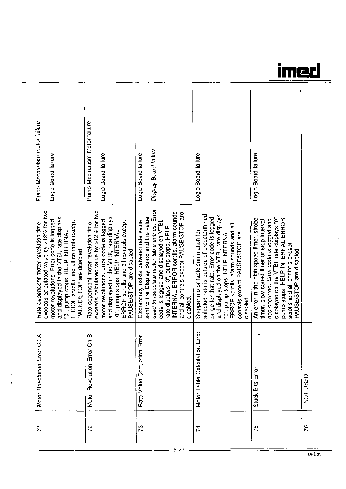
cl
эапив)
оюш
einie)
шзиецози
pieog
dund
21607
anllej
iolou
山
siupuoeW
duund
OM]
5Aeldsip
рэбБо|
101
guH
%28
UOIHDIOA8J
|<
Aq
enjpA
JO10LU
pejejnojeo
Juapuadap
sposoxa
ey
VN831NI
$!
2181
эроз
*19.LA
“013
di3H
9u)
"SUORN|OASI
“sdojs
ul
paÁejdsip
dund
JOJO
pue
“0,
1deoxa
slonuoo
Ile
pue
Sllolos
HO8H3
OM]
104
al
%z|<
uolnloAal
Aq
“paigesip
aniea
loloUu
palejnojeo
E
juapuedap
dOLS/ISNVd
spasoxa
9JEH
ange;
pjeog
91607
sÅejdsip
paBBoj
si
2p09
10113
"SUOInIOA9」
』010UU
1daoxa
TVNH3JNI
slonuoo
этел
'Ig
LA
d13H
lle
au)
pue
'sdols
UI
silojos
P9ABIdSID
duind
HOHH3
DUB
‘,0,
eine;
ajnjej
pieog
pieog
Aeidsig
21807
40113
enjea
anjpa
"S9JiU9
eu}
ayes
pue
ааа
ugamjeq
Ῥθιαξςῃρ
pieog
JOJO
sisixa
ÁRIdsig
ase
dOLS/ASNVd
а1епоео
Aouedaosiq
au]
O]
이
pasn
14105
SPunoS
BIB
"ISLA
uo
pafejdsip
pue
pabbo;
si
apoo
dO
day
LS/ISNVA
uuJBIB
‘sdois
“SIIOJ9S
dund
Ideoxa
HOHH
‘,0,
sjoguos
ヨ
sAeidsip
]VNH
pe
ヨ
6181
INI
pue
элпуе;
рлеоа
ABO
PauluJajepaid
peB6ol
10)
91
YONELULUNS
9poo
jo
10153
apisino
algej
si
solo
ayes
“paiqesip
payoajas
J9ddajs
SABIdsID
WNUALNI
ayes
"Ig
LA
d73H
э\4
‘ayes
чо
‘sdois
psÂeidsip
yeu
dund
JO,
abues
pue
‘.0,
Je
pue
ale
dOLS/38NVd
spunos
wieye
/5ΙΙ0195
Idaoxe
“paiqesip
ΒΟΗΝ3
sjoguoo
Θ1Η/ΒΙ
ΡΙΕΟΒ
91607
aqons
рие
pesou!
ΡΘΒΡΟΙ
Jum
days
5!
pesds
10
θρ0ο
saw
1013
ybiy
pasds
oL
ῬθμΠουο
MOJS
Ul
Joe
‘own
5811
uy
*.0,
HOHH
sÁejdsip
ヨ
]YNH
1daoxa
9181
Ja
LA
aui
uo
paAeldslp
‘рачезр
ヨ
1NI
зодиоо
d1
эле
ヨ
H
JOLS/ASNYd
(¡2
"Sdols
pue
5100$
duund
V
UD
103
VOHNIOADY
JOJO
E
A
UD
1013
UONNIOABY
JOLOA
ol
1043
yondnuo9
8016
ΘΙΘΗ
eZ
5-27
10113
ΗΟΛΕ/ΠΟΙΒΟ
ΘΙΕ1
JOJO
Vl
40113
syg
NOMS
SL
G3ISN
LON
924
UPDO3
Page 28
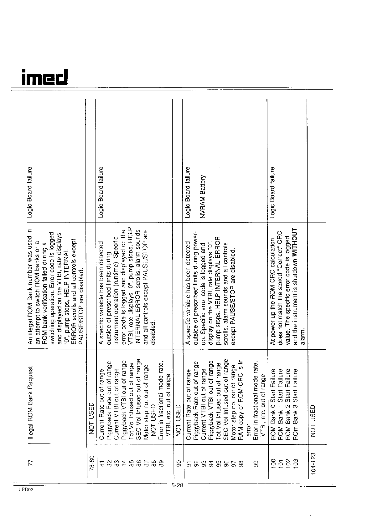
品
힌
미티
01609
91607
ul
pesn
sem
Jequinu
дива
ион
тебе
uv
isenbay
хиея
NOY
¡269111
paB&oj
2
e
10
Buunp
sı
SYUEG
apo9
Pelle;
WOH
10113
UONBOJUSA
Woilws
᾿ΗΟΠΒΙΘάΟ
0}
Idwane
хиеа
ΒΙΠΗΟΗΛΑς
WOH
ue
sABIdsID
1dgoxg
VNH
ayes
SIOJUOO
ヨ
"pajgesip
1NI
‘IQ
LA
d]1
IIE
ay]
ヨ
PUE
H
uo
padeidsip
pue
эле
“Sdols
SIIOJO5
dOLS/ASNVA
dund
HOHH
“,0,
ヨ
85Η
LON
ainyrey
pieog
21607
eur
2J!O9dS
[12819]
4000
564
9IdBJBA
OHIO9dS
V
afuel
10
Ino
ajey
]u9nno
uo
paéerdsip
Buunp
(aumgury)
SIIUJIl
pue
P9dIJOS8」d
UOHBJ9do
JUSUUTJ1SUI
Jo
splsino
9Bue,
abues
jo
¡0
1no
1n0
ayey
|4LA
yoeqABbid
INT
d13H
SpunOoS
ae
dOLS/ASNWd
‘sdojs
LUJBIE
duind
"SIIOJOS
‘,0,
Idaoxa
pa66o]
HOdd
sAeidsip
SIOJJU09
ヨ
st
]VNH
9poo
ayes
¡e
ヨ
‘IG
JLNI
Jolle
aBues
jo
ino
jg
LA
yoeqAbBld
pue
LA
aBue
a6ue
86461
jo
jo
]
jno
ㅇ
jno
100
pasnju]
pasnjuj
“04
0815
¡OA
JOA
10104
DIS
IOL
“paiqesip
“3]2J
Bue
apou
jo
¡euonoBa]
jno
aasn
LON
"98
Ul
LA
10119
dasn
LON
aunyrey
pieog
01607
-Jamod
pajoajep
6uunp
ussq
SHIuull
sey
paqu2seld
ajqenea
Jo
ogads
episyno
y
эбиел
aBues
jo
no
jo
jno
eje
ayey
y
26dA66id
juaung
Aeneg
VEAN
HOHH3
“0,
pure
sAvidsip
pg56o|
IVNUILNI
sl
ayes
epoo
‘|G
d13H
LA
」oJJ8
ay}
‘dos
oyloeds
uo
Aeidsip
dund
‘dn
abue,
aBuel
эбие
jo
jo
1no
10
mo
1по
Ja
pasmyu]
LA
19
[Л
yoeqABBlg
149441095
¡OA
101
slonuoo
"pojgesip
le
pue
9JB
dOLS/ASNYA
Spunos
wJeje
'sjjoJs
1daoxa
afuei
ul
aBue)
SI
OYONOH
jo
jo
ino
ino
pasnjuj
‘ou
49
dals
Ado9
JA
10)0NN
VH
DIS
"9181
apo
¡euonoe
Li
10118
10117
aunyey
pueog
01607
O9
uoOIBIn2IB9
.108H09,
OHO
PSIOIS
мон
SU}
au)
yoyew
dn-Jamod
jou
seop
зу
9JnIE
9JnIIB
oBueu
BIS
HB1S
jo
jno
0
|
‘Na
1468
1468
‘IBLA
ИОН
WOU
JNOHLIM
poBBoj
si
UMOPINUS
apo9
1018
SI
Ajdads
JUBUINISU]
au
AU)
"шее
"aner
PUE
aunile4
эп
3
WEIS
17815
€
Z
HUEg
HUEA
NOY
WOY
q3Sn
LON
Li
UPD03
08-84
18
σ8
$8
78
98
98
48
88
68
06
5-28
16
96
v6
co
06
96
46
86
66
00!
LOL
201
col
ez
tro!
Page 29

cl
ane
pieog
51607
juaun4s
*D9JJn9oO
ey,
SBU
pue
‘ayeys
Θ1Π/Β/
0866
Bopyayem
156]
이
이
ΒοριΟΙΒΛΝΨ
9002
e
519119
1013
ane
ΘΙΠΙΕ:
wine
pseog
91607
8poo
Buunp
10419
G|
yorew
yUeg
‘uoNesado
Jou
WOH
saop
Bulyoims
Sinpayos
Jequnu
yUeG
10
al
Jequnu
WOH
NO8
Z
£
|
1468
NUBA
1468
SDunoS
8JB
ae!
‘|G
LA
ul
padejdsip
pure
pab6o|
si
JO1S/
LUJBIB
d
ヨ
15H
ST1Vd
“SIIOJOS
'sdojs
1d92xg
HOHH
duind
SIOU09
ヨ
',0,
]VNH
sAejdsip
¡pe
ヨ
pue
」NI
"pojqesip
AIUES
1581!
ροµθα
J9uIL
5opdoleAA
ΒορΙ/ΟΙΕΛΛ
WO
40861
CISN
Οἱ
ΘΙΠ/5-Ι
LON
WOH
WOH
yoea
yore
이
©}
8JnI!B
aunyie4
ゴ
vel
Gel
get
tel
601
gel
5-29
UPDO3
Page 30

тес
5.5.2.3
(Figure
1.
Use a #1
screw
harness
5.5.2.4
Door
Sensor
6-2)
Phillips
and
washer
to
the
AIL/SCD
Disassembly
Assembly
screwdriver
that
front
case.
Assembly
(Figure
attach
Removal
6-2)
Removal
to
remove
the
door
and
the
sensor
When
assembly,
must
reinstalling
be
slipped
transducer
alignment.
start,
then
screws
Perform
to
Section
NOTE
IMED
fixture
over
assembly
Position
tighten
Table
5-3
5.7
the
transducer
P/N
and
to
ensure
the
special
the
four
Torque
Calibration.
1320-4077
seated
proper
washers,
mounting
Values.
on
the
Removal
paragraph
access
screws.
1.
Use a #1
four
AIL/SCD
2.
Tilt
the
position
prohibit
projections
3.
Remove
front
5.5.2.5
6-2)
Removal
paragraph
access
mounting
The
assembly
REPAIR
of
the
5.5.2.2)
to
the
Phillips
screws
and
assembly
front
and
open
the
sear
on
the
case.
Transducer
of
5.5.2.2)
to
the
screws.
transducer
level.
AND
NOTE
pumping
is
AIL/SCD
screwdriver
washers
to
case
assembly
the
from
the
slide
AIUSCD
Assembly
NOTE
the
pumping
is
Transducer
is
not
DO
REINSTALL.
mechanism
required
Assembly
that
the
front
to
door
latch.
engaging
clamp
assembly
mechanism
required
Assembly
supported
NOT
ATTEMPT
to
provide
to
remove
attach
case.
the
upright
This
the
housing.
from
Removal
to
provide
(see
mounting
the
the
will
ramped
the
(Figure
(see
below
the
TO
5.5.2.6
(Figure
1.
Anchor
6-2)
Use a #1
screw
anchor
Use
pliers
down
the
hairpin
downward
expand
washer
Tilt
the
open
and
remove
5.5.2.7
Disassembly
1
2.
Access
Unlatch
Use a 1/32
depress
the
lower
pivot
the
door
using a finger
recess.
door
Bracket
Phillips
that
attaches
bracket.
to
grasp
and
compress
cotter.
press
to
full
length,
and
spring
front
case
the
door
latch,
the
Door
(Figures
and
open
inch
the
tip
of
surface
projection,
away
from
to
Once
the
out
of
the
lower
Assembly
screwdriver
the
ground
the
washer,
the
spring,
Carefully
on the
anchor
or 1 mm
then
trap the
spring
then
from
to
the
swing
bracket.
Assembly
6-2
and
the
door.
the
upper
of
the
ease
the
hinge
hinge
NOTE
the
front
front
to
wire
release
allowing
remove
anchor
upright
the
door
Removal
6-3)
drift
punch
hinge
case
the
upper
case
hinge
pin
is
clear,
pivot
Removal
remove
then
and
position,
pin
projection.
the
to
the
press
remove
the
it
the
bracket.
open
and
to
pin
below
hinge
edge
while
in
its
lift
to
of
the
1.
Use a #1
four
(square)
to
the
2.
Slip
adhesive
harness
3.
Lift
case.
Phillips
epoxy
that
front
the
transducer
backed
to
the
transducer
lock
attach
case.
the
screwdriver
screws
the
harness
wire
clip
front
case.
assembly
to
remove
and
special
transducer
clear
that
holds
out
of
washers
assembly
of
the
the
the
front
the
5-32
The
to
washer.
washer
の
Use a 1/8
dowel
assembly
dowel
the
door
When
must
pin
pin
is
inch
that
{door
that
attaches
retained
removed,
be
replaced.
drift
punch
attaches
latch)
the
by a spring
the
spring
to
knock
the
cam
to
the
door.
cam
lock
out
lock
the
Page 31

4.
Use a 1/8
spring
lock.
5.
Use a 1/16
spring
the
5.5.2.8
To
necessary
pin
pin
door.
Pump
remove
mechanism
provide
connection.
1.
Use a 1/4
pliers
to
wire
connection
from
the
screwdriver.
2.
Remove
bezel.
3.
Use a straight
edge
of
recess.
4.
Pull
the
case.
inch
drift
that
attaches
inch
that
attaches
Seal
the
to
first
(see
access
inch
offset
hold
the
while
front
side
the
remaining
slot
the
bezel
urethane
punch
the
drift
punch
the
Removal
NOTE
pump
seal
remove
paragraph
to
the
bezel
wrench
nut
on
removing
with a #1
nine
screwdriver
out
of
pump
seal
NOTES
to
knock
sear
to
cam
(Figure
bezel,
the
5.5.2.2)
the
bezel
Phillips
screws
the
from
out
to
the
knock
lock
out
pawl
6-2)
it
is
pumping
to
grounding
or
needle
ground
the
screw
from
to
pry the
front
case
the
the
cam
the
to
nose
the
top
front
5.5.2.10
Keypad/ESD
Removal
The
laminated
shield
assembly
adhesive
front
case.
reusable.
1.
Use a #1
screw
grounding
front
2.
copper
dispose
5.5.2.11
5.5.3
The
sequenced
case.
rear
that
case.
Peal
the
ESD
of
DELETED
Rear
Case
following
for
All
subassemblies
case
are
independently
5.5.3.1
Battery
11)
Shield
(Figure
6-2)
NOTE
front
is
backing
Once
Phillips
which
removed,
screwdriver
connects
tab
to
the
laminated
shield
front
from
it.
Disassembly
disassembly
complete
directly
removed
accessible
and
Assembly
imeci
Assembly
label/keypad/ESD
manufactured
bonds
it
is
to
remove
the
ESD
shield
threaded
procedures
disassembly
installed
lug
label/keypad
front
case
of
on
the
and
can
replaced.
Removal
with
it
to
the
not
on
the
and
and
are
the
rear
interior
be
(Figure
an
the
6-
Prior
seal,
100
When
torque
in.
5.5.2.9
1.
Use a #1
screw
front
to
installing a replacement
coat
the
inside
pL
of
Silicone
reinstalling
the
bezel
Snap
Bracket
Phillips
that
attaches
case.
oil
the
mounting
Removal
screwdriver
the
of
(P/N
pump
snap
the
seal
1025-100).
seal
screws
(Figure
to
bracket
pump
with
assembly,
to 3 Ib-
6-2)
remove
to
the
the
5-33
1.
Lay
surface.
2.
Use a #4
the
the
and
3.
Lift
5.5.3.2.
(Figure
1.
Use a #1
two
audio
2.
Lift
rear
the
rear
straight
two
screws
battery
remove
the
battery
Audio
6-11)
Phillips
screws
oscillator
the
audio
case.
case
down
slot
and
retention
the
strap.
out
of
Harness
screwdriver
and
washers
to
the
harness
on
the
screwdriver
lock
washers
strap
to
the
rear
Assembly
that
rear
case.
assembly
working
that
the
rear
case.
Removal
to
remove
attach
out
to
remove
attach
case
the
the
of
the
Page 32

imed
FINAL
FRONT
PUMPING
ASSEMBLY
Front
Multicard
ESD
Bezel
Snap
Pumping
Transducer
Door
AIL/SCD
Ground
Bearing
Left
to
Pump
Vibration
Motor
Motor
Motion
REAR
CASE
Audio
Transistor
Audio
Functional
Case
to
CASE
Assy
Shield
Sensor
Ground
to
Front
Bracket
Mechanism
Assy.
Assy.
Harness
MECHANISM
Cup
Right
Housing
Mounts
Bracket
Bracket
Sensor
Harness
Harness
Control
to
to
to
Pump
Application
Rear
Case
to
Front
to
Case
Front
to
to
Front
Front
to
Front
to
Anchor
Top
Plate
Housing
to
Top
to
Motor
to
Vibration
to
Top
to
Top
Assy
to
to
Switch
to
Case
Front
Case
Front
Case
Case
Plate
Plate
Plate
Rear
Rear
Rear
Table
Case
Case
Case
Bracket
Assy.
Assy.
Housing
Mounts
Assy.
Assy.
Case
Case
Case
5-3.
Table
Description
#10-32 x 3/8
#4-40 x 3/4
#d-40 x 3/16
#4-40 x 1/2
#4-4- x 3/16
46-32 x 3/8
46-32 x 3/8
lock
washer)
44-40 x 1/4
#4-40
#4-40 x 1/4
#4-40 x 3/16
46-92 x 1
#6-32 x 3/8
#4-40
Rubber
#4-40 x 5/16
44-40 x 5/16
#4-40 x 3/8
#4-40 x 1/2
#4-40 x 1/4
Nut
of
Torque
Нет
x1/4
EL
Shldr
Mount
EL
(with
EL
EL
EL
Values
Figure/ltem
Reference
6-1/7
6-2 6 &7
6-2 / 12
6-2 / 15
6-2 / 18
6-2 / 21
6-2 / 21
6-2 / 23
6-2 / 27
6-2 / 31
6-2 / 39
64/8
6-4 / 28
6-4 / 24
6-4/19
6-4 / 15
6-4 / 15
6-4 / 3 3
6-11 / 17
6-11 / 24
6-11 / No
Ref
Torque
Value
71600
3
Ib-in
3
ib-in
3
Ib-in
3
Ib-in
2
Ib-in
[ν2.χχ]
7
Ib-in
[v3.xx]
2
Ib-in
3
Ib-in
3
Ib-in
3
Ib-in
3
Ib-in
3
Ib-in
8
ib-in
Finger
5
5
3
5
3
Tight
Ib-in
Ib-in
lb-in
Ib-in
Ib-in
Ib-in
When
Replacement
IMMOBILIZE
§.7
STRAIN
Anytime a Strain
assembly
or
component
schematic
following
be
patient
ет
Logic/Analog
has
or
calibration/adjustment
performed
care
epoxy
BEAM
been
replaced,
board
in
the
{see
figure
prior
service.
lock
screws
A
STANDARD
CALIBRATION
Beam
(pressure
removed
the
[v3.xx]
strain
beam
4-5)
to
returning
(EL)
are
Analog
is
screws
available
SCREW.
transducer)
from
the
Board
is
changed
functional
replaced;
procedure
the
instrument
are
removed
from
front
[v2.xx]
or
the
MUST
CAUTION
IMED
If a lock
case
a
to
always
Service
washer
5-36
replace
Centers.
is
installed
with a new
USE
ONLY
DO
NOT
epoxy
LOCTITE
use
lock
glue.
screw.
425
TO
UPDO3
Page 33
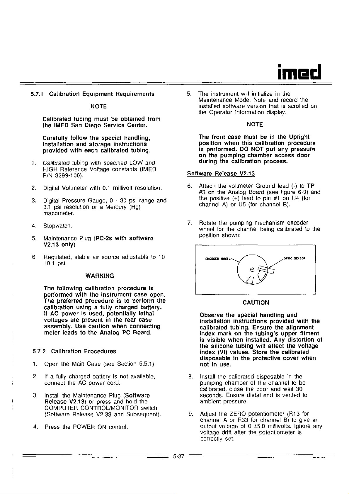
5.7.1
Calibrated
the
Carefully
installation
provided
Calibrated
HIGH
P/N
Calibration
tubing
IMED
San
follow
and
with
tubing
Reference
3299-100).
Equipment
NOTE
must
Diego
each
Service
the
special
storage
calibrated
with
specified
Voltage
Requirements
be
obtained
Center.
handling,
instructions
tubing.
LOW
constants
from
and
(IMED
The
Maintenance
installed
the
The
position
is
on
during
Software
instrument
software
Operator
front
case
when
performed.
the
pumping
the
calibration
Release
will
initialize
Mode.
Note
version
Information
NOTE
must
be
this
calibration
DO
NOT
chamber
process.
V2.13
imed
in
the
and record
that
is
scrolled
display.
in
the
Upright
procedure
put
any
pressure
access
the
on
door
Digital
Digital
0.1
manometer.
Stopwatch.
Maintenance
V2.13
Regulated,
+0.1
The
performed
The
calibration
if
AC
voltages
assembly.
meter
5.7.2
Calibration
Open
Voltmeter
Pressure
psi
resolution
only).
stable
psi.
following
with
preferred
power
are
Use
leads
the
Main
with
0.1
millivolt
Gauge, 0 -
or a Mercury
Plug
(PC-2s
air
source
WARNING
calibration
the
instrument
procedure
using a fully
is
used,
present
caution
to
the
Procedures
Case
potentially
in
the rear
when
Analog
(see
resolution.
30
psi
(Hg)
with
software
adjustable
procedure
case open.
is
to
perform
charged
connecting
PC
Board.
Section
range
and
to
is
the
battery.
lethal
case
5.5.1).
10
Attach
#3
the
the
on
the
positive
channel
Rotate
wheel
Position
ENCODER
the
for
shown:
WHEEL
Observe
installation
calibrated
index
mark
is
visible
the
silicone
index
(VI)
disposable
not
in
use.
voltmeter
Analog
(+)
lead
A) or
U5
pumping
the
channel
CAUTION
the
special
instructions
tubing.
on
the
when
tubing
values.
in
the
Ground
Board
(for
(see
to
pin
channel
mechanism
being
ss
handling
provided
Ensure
tubing's
installed.
will
affect
Store
the
protective
lead
(-)
figure
#1
on
U4
B).
encoder
calibrated
OPT
SENSOR
and
with
the
alignment
upper
Any
distortion
the
voltage
calibrated
cover
to
TP
6-9)
and
(for
to
the
the
fitment
when
of
If a fully
connect
Install
Release
COMPUTER
(Software
Press
charged
the
AC
the
Maintenance
V2.13)
CONTROUMONITOR
Release
the
POWER
battery
power
or
press
V2.33
ON
is
not
cord.
Plug
(Software
and
and
control.
available,
hold
the
switch
Subsequent).
5-37
Install
the
calibrated
Pumping
calibrated,
seconds.
ambient
Adjust
chamber
close
Ensure
pressure.
the
ZERO
channel A or
output
voltage
correcily
voltage
drift
set.
disposable
of
the
door
distal
potentiometer
R33
for
of O
+5.0
after
the
in
the
channel
and
end
wait
is
vented
to
(R13
channel
B)
to
millivolts.
potentiometer
the
be
30
to
for
give
Ignore
is
an
any
Page 34

тес
10.
11.
12.
13.
14.
15.
16.
Connect
#1
Apply
end
minimum
Adjust
(for
and
of
the
channel
maintain
the
calibration
of
the
SPAN
channet A or
voltage
voltage
minus
output
for
LOW
the
instrument's
V2.13 - 3.0
Adjust
the
ZERO
channel A or
voltage
voltage
version.
Release
is
At
This
Reference
with
repeat
Press
down
is
equal
(+0.01
the
vented
30 +5
to
seconds,
voltage
voltage
the
calibrated
steps 7 and 9 through
the
PAUSE/STOP
the
instrument.
positive
A)
or
10.0
15
seconds.
potentiometer
R36
for
is
equal
calibrated
Reference
installed
volts).
potentiometer
R33
for
to
the
volts)
pressure,
ambient
read
must
be
(10.1
WARNING
(+)
voltmeter
TP
#2
(for
+0.1
psi
disposable,
channel
to
B)
the
differential
disposable
voltage
software
channel
HIGH
for
the
installed
version,
B)
Reference
ensuring
pressure.
the
output
equal
disposable;
to
volts)
control
lead
channel
to
the distal
then
(R17
until
(HIGH
for
your
(R13
until
the
distal
voltage.
the
provided
if it
15.
to
power
to
TP
B).
wait
a
for
the
i.e.
for
the
software
end
LOW
is
not,
10.
Attach
U4
channel
on
Actuate
(for
the
the
Analog
CONTROL/MONITOR
Voltage
*
"A
Information
control
Observe
tion
instructions
brated
mark
on
visible
the
silicon
index
(VI)
posable
in
use.
11.
Install
pumping
20
the
seconds.
ambient
Adjust
12.
channel A or
stable
output
adjustment,
DVM
channel
B)
and
the
COMPUTER
Test,
then
strain"
will
once
the
special
tubing.
the
tubing
when
tubing
values.
in
the
installed.
calibrated
chamber,
Ensure
pressure.
the
ZERO
R34
of 0 43.0
disconnect
positive
A)
or
pin
the
ground
Board.
switch
press
appear
display
to
select
(press
CAUTION
handling
provided
Ensure
upper
will
Store
protective
disposable
close
distal
potentiometer
for
channel
the
(+)
lead
#1
(-)
START.
on
"B
with
the
alignment
fitment
Any
affect
the
cover
the
end
mV.
Following
DVM.
to
pin
of
US
(for
lead
to
to
select
the
Operator
PAUSE/STOP
strain").
and
installa-
the
is
distortion
the
voltage
calibrated
when
in
the
door and
is
vented
(R13
8)
to
give
#1
TP#3
A/D
cali-
index
of
dis-
not
wait
to
for
a
of
17.
18.
Software
6.
The
Maintenance
prior
to
service
Remove
returning
for
patient
the
Plug
the
care.
Maintenance
instrument
Perform a Comprehensive
Performance
Release
Actuate
MONITOR
the
switch
Test
(See
V2.33
COMPUTER
to
and
select
Test.
Press
START,
Controls
channel
Press
START.
should
procedure).
match
to
to
select
be
then
use
Motor
calibrated.
(Encoder
figure
shown
must
be
Plug.
Operational
Section
5.8).
Subsequent
CONTROL
the
Motor
the
Data
Step
150
wheel
position
in
V2.13
removed
to
Homing
Input
for
the
5-38
Connect
13,
TP#1
B).
Apply
14.
end
minimum
Adjust
15.
channel A or
VTBI
Adjust
16.
channel A or
VTBI
calibrated
VI,
value.
17.
Release
disposable’s
pressure.
the
(for
and
of
the
the
display
the
display
plus
2.50
the
positive
channel
maintain
(+)
A)
10.0
calibration
of
15
seconds
SPAN
ZERO
potentiometer
R36
for
reads
2.50
potentiometer
R34
for
equals
the
disposable’s
+0.01.
Record
pressure,
distal
end
voltmeter
or
TP#2
(for
+0.1
psi
disposable.
before
proceeding.
(Ri7
channel
B)
10.01.
(R13
channel
zero
ensuring
is
sum
pressure
the
vented
B)
of
the
final
the
lead
to
channel
to
the distal
Wait
a
for
until
the
for
until
the
index
voltage
to
ambient
Page 35

18.
1
I°
21.
22.
23.
Fractional
6.
7.
8.
9.
After 30 +5
This
not
repeat
actual
9.
Open
Ensure
or
0.01.
Using
strain
fully
strain
between
not
Technical
Press
switch,
the
instrument.
reading
deflect
within
seconds,
must
steps 7 through
voltage
the
the
your
beam
value.
door.
VTBI
finger,
finger
the
beam
voltage
4.90
and
this
Service.
COMPUTER
then
PAUSE/STOP
strait
range,
Perform a Comprehensive
Performance
Actuate
MONITOR
Test
Keypad/Series
the
COMPUTER
switch
Test.
Press
START,
Controls
channel
Press
START.
should
match
to
to
select
be
then
calibrated.
(Encoder
figure
procedure).
Attach
channel
ground
the
A) or
(-)
DVM
lead
TP4
to
Board.
10.
11.
Actuate
MONITOR
then
+
Press
the
VTBI
and
range,
the
COMPUTER
switch
press
START.
“A
strain"
wil
Information
the
Operator
display
2.53.
control
Information
shows a value
If
the
contact
display.
read
the
equal
VI,
17.
reading
gently
with
drops
press against
sufficient
beam;
in
the
VTBI
5.15.
If
the
contact
CONTROUMONITOR
to
Operational
(see
Section
v3.xx
CONTROL
to
select
the
use
the
Motor
Step
wheel
shown
positive
(for
TP#3
in
(+)
channel
on
the
CONTROL/
to
select
A/D
appear
until
on
"V
display.
reading
IMED
is
Technical
VTBI
+0.01;
if it
Record
to
either
pressure
confirm
display
reading
IMED
power
5.8).
Software
Motor
Data
Input
150
for
position
V2.13
lead
TPS
B)
and
Logic/Analog
Voltage
the
Operator
yes"
appears
Ensure
between
not
within
Service.
display.
does
the
0.00
the
to
the
is
is
down
Homing
the
(for
the
Test,
in
the
2.47
this
+2.
Press
in
the
the
(0)
Observe
tion
brated
mark
visible
the
index
posable
in
use.
13.
Install
pumping
20
seconds.
ambient
14.
Adjust
channel A or
stable
15.
Connect
TP#1
B).
16.
Apply
end
minimum
17.
Adjust
channel A or
VTBI
18.
Adjust
channel A or
VTBI
calibrated
VI,
value.
19.
Release
disposable's
pressure.
20.
After
This
not
actual
21.
Open
the
[cy
control
Operator
control
the
once
special
instructions
tubing.
on
the
tubing
when
silicone
(Vl)
the
installed.
tubing
values.
in
the
calibrated
chamber,
Ensure
pressure,
the
ZERO
R34
output
(for
and
of
the
display
the
display
of 0 +3.0
the
positive
channel
maintain
the
calibration
of
15
SPAN
R36
reads
ZERO
R34
equals
disposable’s
plus
2.50
+0.01.
the
pressure,
distal
30
+5
seconds,
reading
repeat
the
must
steps 7 through
voltage
value.
door.
until
“A
Information
to
select
CAUTION
handling
provided
Ensure
the
upper
Any
will
affect
Store
the
protective
disposable
close
the
distal
end
potentiometer
for
channel
mV.
(+)
voltmeter
A)
or
TP#2
10.0
+0.1
disposable.
seconds
potentiometer
for
2.50
before
channel
+0.01.
potentiometer
for
channel
the
sum
zero
Record
ensuring
end
is
vented
read
equal
VI,
imed
strain"
display.
with
alignment
fitment
cover
door
pressure
the
the
+0.01;
17.
appears
(Press
"B
strain").
and
installa-
the
cali-
is
distortion
the
voltage
calibrated
when
in
the
and
wait
is
vented
(R13
for
B)
to
give
lead
(for
channel
psi
to
the
Wait
a
proceeding.
(R17
for
B)
until
the
(R13
for
B)
until
the
of
the
index
final
voltage
the
to
ambient
VTBI
display.
if it
Record
index
to
does
the
of
dis-
not
to
a
distal
5-39
UPD03
Page 36

imed
22.
Ensure
23.
Using
strain
fully
strain
between
hot
Technical
24.
Press
switch
Operator
to
power
25.
Perform a Comprehensive
Performance
5.8
COMPREHENSIVE
PERFORMANCE
The
comprehensive
should
removed
jected
opened.
meet
specified
to
necessary
deficiency
restore
the
instrument
the
your
beam
deflect
beam
4.90
within
COMPUTER
until
Information
down
be
performed
from
servicing
In
the
to
troubleshoot
and
full
operational
VTBI
reading
finger,
this
finger
the
strain
voltage
and
range,
gently
with
5.15.
Service.
"Powerdown
the
Test
(see
TEST
operational
on
service
event
test
perform
for
that
required
an
performance
the
capability
to
service.
drops
to
0.00.
press
against
sufficient
beam;
in
the
If
contact
confirm
VTBI
the
pressure
display
reading
IMED
CONTROL/MONITOR
Test"
appears
display.
instrument.
Press
Operational
Section
5.8).
OPERATIONAL
performance
any
PC-2
that
repair
or
has
the
case
instrument
should
criteria,
specific
repairs
areas
needed
prior
to
the
to
the
is
is
in
the
START
test
has
been
been
sub-
to
be
fail
to
it
will
be
of
to
returning
5.8.3
The
Gesigned
accordance
Quantitative
Test
following
to
procedures
areas
of
instrument
5.8.3.1
1.
Equipment
Universal
+
Selector
*
10
+
Pressure
within
» o 36"
stick).
2.
Gas
tight
3.
Stopwatch
second.
4.
Vented
5.
GEMINI
injection
6.
Waste
7.
Nurse
operational
ensure
with
design
are
provided
test
station:
valve
mL
Volumetric
gauge,
2.0%
view
tube
syringe,
with
bottle
or
Non-vented
sites.
fluid
catch
Call test
Operational
performance
the
PC-2
is
specifications.
to
evaluate
performance.
Requirements
(see
Fig
manifold
burette
0-60
psig,
or
better
(macrobore
100
ul
capacity.
minimum
bag
resolution
of
Normal
administration
basin.
lamp.
Performance
tests are
functioning
Test
specific
5-2).
accurate
tubing
on
of
Saline.
set
in
yard
1
with
2
5.8.1
The
Leakage
Perform
for
Patient
022.2
Test
5.8.2
Test
The
mance
control,
ation
those
normal
power
qualitative
accordance
Section
UPDO3
Electrical
electrical
Test
these
inspection
and
tests
Care
No.
125
for
parameters
Qualitative
abbreviated
test
will
check
displays
in
the
Pump
audio
and
instrument
down
sequence.
operational
with the
2.3.3.2.
Inspection
consists
Electrical
in
compliance
Equipment
Risk
are
described
and/or
Class
Operational
qualitative
and
and
visual
operation
operational
the
PC-2’s
indicators;
Controller
alerts
Perform
performance
procedures
of
the
Ground
Test.
with
CSA
2G
Equipment.
in
Section
Performance
keypad,
instrument
modes
associated
and
the
instrument
the
abbreviated
test
described
Electrical
UL
544
Standard
2.3.2.
perfor-
audio
oper-
including
with
in
in
8.
Maintenance
9.
Test
5.8.3.2
The
following
sequence
protocols
an
expeditious
identical
channel A testing
TEST
SETUP
1.
Spike a vented
Saline
vented
solution
closed.
2.
Connect
the
5-40
Plug
Data
Sheet
Test
Procedures
test
procedures
that
will
allow
to
be
accomplished
and
for
channel
repeat
or
tap
water
administration
test
stand.
the distal
input
side
of
(Software
(see
figure
the
required
efficient
B;
botile
upon
for
or
manner.
channel
with a GEMINI
set
Check
end
of
the
stopcock
Release
5-3).
are
presented
test
accurately
Tests
completion
B.
bag
of
Normal
and
hang
the
roller
the
tubing
manifold.
V2.13).
and
are
of
Non-
on
clamp
set
in
in
the
to
a
IV
Page 37

HEIGHT
・
VIEW TUBE
LOWER
LIMIT
CONTROLLER
OCCLUSION
|
MOO-
PRESSURE
|
|
|
24° (61
om)
TR
PRFSSURF
GAUGE
10
ml
SURETTE
グ
Figure
5-1.
Universal
STOPCOCK
MANIFOLD.
Test
5-44
Station
Setup
Page 38

imeci
Set
the
through
Flood
clamp,
stopcock.
Adjust
provide a measured
cm)
i.e.,
the
strain
container.
stopcocks
the
manifold
the
drip
prime
the
the
height
24"
of
beam
to
allow
to
chamber,
set
then
of
the
head
vertical
and
the
fluid
to
the
fluid
catch
open
the
roller
close
the
solution
displacement
fluid
height
level
container
of
pass
second
24"
between
in
the
basin.
to
(61
Turn
5.
waste;
the
OUTPUT
1.
Turn
the
Select
Press
stopcock
drain
stopcock
PRESSURE
stopcock
pressure
PUMP
START
#3
to
drain
to
the 0 graduation,
to
the
bypass
TEST
#1
to
direct
gauge.
mode.
and
observe:
the
fluid
position.
pump
column
then
turn
output
to
to
Install
PC-2;
Ensure
stopcock
primed.
Press
CHANNEL
Select
125
LOW-FLOW
1.
Turn
to
the
mark
in
the
Press
+ © Fluid
ㆍ
«
the
tubing
close and
the
tubing
manifold
POWER
A.
CONTROLLER
mLhr
and
HEİGHT
stopcock
36"
view
on
the
solution
START
column
Pumping
Audio
Advisory
set
latch
segment
and
ON
control
set
VTB!
TEST
#3
to
tube
view
tube
container.
and
observe:
rises
mechanism
in
channel A of
the
access
between
the
pressure
and
mode,
to
100 ml.
direct
the
only.
Ensure
is
level
in
the
stops
sounds
ACCESS
set
pump
with
view
the
door.
the
gauge
RATE
output
the
the
tube
to
18"
fluid
is
+ © Pumping
+
+
Record
sheet
must
Silence
then
Turn
momentarily
turn
PUMP
PRESSURE
Initialize
Press
switch
Press
mechanism
Audio Alarm
sounds
"OCCLUDED-PATIENT
continuously.
pressure
immediately
be
between 8 and
alarm,
press
stopcock
back
to
gauge
following
Press
ACCESS
PAUSE/STOP
#1
to
the
to
relieve
the
pressure
TEST
instrument
COMPUTER
to
select
START
in
CONTROUMONITOR
"pump
control
stops
reading
12
once.
bypass
the
pressure
gauge
the
Maintenance
test".
twice.
SIDE”
on
alarm
psi).
CHANNEL
position
scrolls
the
data
(reading
and
then
position.
Mode.
A,
*
"LOW
FLOW"
minute
»
After 1 minute
Alarm
and
continuously.
Record
view
be
Silence
then
the
height
tube
on
between 6 and
alarm,
press
PAUSE/STOP
advisory
audio
“OCGLUDED"
of
the
the
data
30
inches).
press
ACCESS
alert
fluid
sheet
once.
scrolls
changes
scrolls
column
(reading
CHANNEL
for
1
to
in
the
must
A,
5-42
Verify
mL.
operate
the
rate set
Press
START
for
peak
Record
the
obtained.
psi.
Press
PAUSE/STOP
down
the
to
125
control
at
least
30
pressure
highest
stabilizes.
pressure
Resultant
instrument.
mUhr
and
and
allow
seconds
pressure
control
VTBI
the
and
reading
must
twice
pump
to
>25
wait
be
>17
power
to
until
Page 39

im
8.
Turn
the
Test
bypass
Station
position.
stopcock
#1
to
the
NURSE
CALL
MAINTENANCE
INTERFACE
MODE
AND
FUNCTIONAL
TEST
VOLUME/RATE/TIME
Software
1.
Software
1.
2.
3.
4.
5.
6.
7.
Release
Perform
tested
Home
pumping
Turn
10mL
Press
line,
PAUSE/STOP
Press
CLEAR
to
Set
to
Press
simultaneously.
When
(see
Release
channel
stopcock
burette.
START
then
VOLUME
"0".
VTBI
125
START
audio
Motor
chamber
press
to
to
ml.
COMPLETE-KVO"
the
stopwatch
CHANNEL
twice.
V2.13
Homing
Section
V2.33
by
#2
to
fill
ACCESS
once.
INFUSED
reset
the
5mL
and
Advisory
and
A
followed
TEST
Test
5.3.2).
and
opening
access
to
direct
the
burette
Volume
and
verify
start
the
sounds
scrolls,
press
by
on
channel
Subsequent
appropriate
door.
fluid
flow
to
the
CHANNEL
followed
Infused
the
RATE
stopwatch
and
"INFUSION
immediately
ACCESS
PAUSE/STOP
to
to
the
10mL
A
and
by
register
is
set
stop
be
The
following
dependent
once.
1.
Remove
2.
Install
the
RS-232-C
3.
Install
Call/Maintenance
4.
Press
5.
Following
initialization
Maintenance
light.
test
6.
Check
7.
Remove
reinstall
8,
Perform
in
order
procedures):
+
Lamp
test)
+
Keypad
procedures
and
need
all
disposables
the
communications
Data
the
Maintenance
POWER
the
ON.
audio
sequence,
Plug
the
Nurse
the
Nurse
the
Maintenance
the
following
(refer
to
test
(vary
test
NOTE
only
Port.
Plug
connector.
tone
remove
and
install
Call
test
Call
Maintenance
section
audio
are
be
from
emulator
Plug
at
the
light
test
light
Plug.
5.3.2
volume
not
channel
performed
the
instrument.
plug
in
the
Nurse
end
of
the
the
Nurse
is
illuminated.
and
Mode
for
during
in
the
Call
test
the
NOTE
Failure
induce a volume
to
stop
the
pump
accuracy
immediately
error
into
will
the
test.
8.
Read
the
fluid
level
in
the
burette.
9.
Record
fluid
the
between
must
limits).
10.
Turn
burette
the
level
data
sheet
4.7
be
within
stopcock
down
volume
from
and
to
delivered
step
#7)
(Volume
5.3
2:16
and
#2
to
drain
the
1OmL
and
delivered
mL
and
2:31
the
line.
(10
mL
elapsed
must
elapsed
(min:sec)
fluid
in
minus
time
be
time
the
on
+
Error
is
log
*
Serial
>
Input
+
Powerdown
9.
Remove
Communication
completion
Log
Display
displayed;
has
been
Port
test
Port
Display
test.
the
Maintenance
Emulator
of
testing.
(clear
‘failed’
message
cleared}.
log
and
Plugs
if
‘newest
indicates
upon
Page 40

imeci
BATTERY
Battery
battery
one
channels
conditions
cycle/day),
original
Usage
result
more
recharge
To
following
operation
is
channel
operating
capacity
other
in
prolonged
than
may
determine
procedure:
CAPACITY
~5
hours
at
125
of
normal
the
battery
after
than
one
discharge/day
reduce
battery
CHECK
with a new,
with
the
mU/hr,
at
that
or
or
125
mL/hr.
usage
should
one
year
described
reduced
battery
capacity
fully
charged
instrument
=4
hours
operating
with
Under
(e.g.,
one
discharge
retain
50%
of
of
usage.
above
battery
without a complete
life).
perform
may
life
the
(i.e.,
both
its
Connect
and
with the
Disconnect
both
Record
point
the
allow
the
instrument
from
channels
the
of
activation
alarm.
If
the
resultant
consideration
the
battery.
battery
replacement.
AC
power
battery
the
at
not
125
cord
to
charge
operating.
AC
source
mL/hr.
battery-operated
of
the
"HELP
run
time
is
less
should
Follow your
be
given
hospital
to
an
AC
for
16
and
operate
run
time
to
BATTERY”
than 2 hours,
to
replacing
protocol
source
hours
the
for
5-44
Page 41

imeci
PC-2
TEST
DATA
SHEET
instrument
Date
Test
No.
1
2
3
4
5
6
7
8
Serial
No.
Description
Electrical
Electrical
Initialization
Keypad
Controller
Pump
Low-Flow
Output
Leakage
Ground
and
Mode
Mode
Air-in-line
Height
Pressure
Test
Test
Display
Operation
Operation
Test
Test
Check
Software
Technician
Version.
Reference
2.3.2.1
2.3.2.2
2.3.3.2
2.3.3.2
2.3.3.2
2.3.3.2
2.3.3.2
5.8.3.2
5.8.3.2
_
A
Ch
Ch
Cha
Ch
CHA
Ch
Ch
ChB
Ch
Ch
Pass/Fail
A
B
B
B
Fluid
A
|...
Pressure
A
B
ot
/
/
/
_
/
/
/7
Height
9
10
11
12
13
Pump
Volume/Rate/Time
Nurse
Maintenance
Battery
Pressure
Call
Test
Mode
Capacity
Test
Test
Check
Figure
Test
5-2.
PC-2
5-45
Test
7
Data
5.8.3.2
5.8.3.2
5.8.3.2
5.8.3.2
§.8.3.2
Sheet
Ch
Ch
B
Ch
ChB
Cha
CH
A
À
B
Pressure
_
Volume
Time
/
/
/
Page 42

imeci
THIS
PAGE
INTENTIONALLY
LEFT
BLANK
5-46
一
=
 Loading...