

Page 1

Alaris
®
GW Volumetric Pump
Technical Service Manual
Page 2

This manual has been prepared for use by qualified service personnel only.
Cardinal Health cannot accept any liability for any breakdown or deterioration in performance of parts or equipment
resulting from unauthorised repair or modification.
t Cardinal Health, 1180 Rolle, Switzerland
Alaris® and Asena® are registered trademarks of Cardinal Health, Inc. or one of its subsidiaries.
All other trademarks belong to their respective owners.
© 2003-2006 Cardinal Health, Inc. or one of its subsidiaries. All rights reserved.
Alaris® GW Volumetric Pump 2/77 1000SM00006 Issue 4
Page 3

Contents
Chapter
1.
2.
3.
4.
5.
6.
Appendix
Introduction & Start up 4
Configuration & Calibration 10
Routine Maintenance 15
Troubleshooting 24
Circuit Descriptions 28
Spare Parts Replacement Procedures 32
Specifications 5
A.
Disposal 6
B.
Spare Parts Listing 6
C.
Fitting and Replacement Guidelines 6
D.
Compatible IV Infusion Sets 6
E.
Configuration Records 7
F.
Service Contacts 7
G.
Document History 7
H.
2
0
2
6
9
2
4
6
Alaris® GW Volumetric Pump 3/77 1000SM00006 Issue 4
Page 4

Introduction & Start up
In this chapter
Introduction 5
General precautions 5
Chapter 1
Views of the Alaris® GW Volumetric Pump 6
Controls and indicators 7
Operating the Alaris® GW Volumetric Pump 8
Starting the Alaris® GW Volumetric Pump 9
Features of the Alaris® GW Volumetric Pump 9
Page 5

Introduction & Start up
Introduction
The Alaris® GW Volumetric Pump is designed to deliver a continuous and accurate infusion. High performance, comprehensive alarm
protection and sophisticated monitoring systems, combined with simple operation, make this pump ideal for general care and critical
care in a variety of areas within a hospital.
The Asena® brand name has been recently changed to the Alaris® brand name. This change in brand name has no effect on the
intended use or functionality of the product. Recommended disposable products for use with this product may refer to either the
Asena® brand name or Alaris® brand name and both types are suitable for use with this infusion pump.
Familiarity
Before operation, ensure that you are fully familiar with this pump by carefully studying the Directions for Use (DFU) prior to
attempting any repairs or servicing.
As part of a policy of continuous improvement, product enhancements and changes are introduced from time to time.
Purpose
This Technical Service Manual describes how to set up, test and maintain the Alaris® GW Volumetric Pump. It is intended for use by
personnel experienced in medical equipment testing and maintenance procedures.
Symbols
Wherever you see this symbol in the manual you will find a Hints & Tips note that we hope you will find useful.
These notes provide useful advice or information that may help you perform the task more effectively.
Wherever you see this symbol in the manual you will find a Toolbox note that highlights an aspect of test or
maintenance that is important for you to know about. A typical example is a software upgrade that you should
check has been installed.
General precautions
Please read the general Operating Precautions described in the Directions for Use carefully prior to using this pump.
w
This pump contains static-sensitive components. Observe strict precautions for the protection of static sensitive
components when attempting to repair and service the pump.
V
An explosion hazard exists if the pump is used in the presence of flammable anaesthetics. Exercise care to locate the
pump away from any such hazardous sources.
B
An electrical shock hazard exists if the casing of the pump is opened or removed. Refer all servicing to qualified
service personnel.
A
This pump is protected against the effects of high energy radio frequency emissions and is designed to fail safe if
extremely high levels of interference are encountered. Should false alarm conditions be encountered, either remove
M
the source of the interference or regulate the infusion by another appropriate means.
If the pump is dropped, subjected to excessive moisture, humidity or high temperature, or otherwise suspected to
have been damaged, remove it from service for inspection by a qualified service engineer.
*
When connected to an external power source, a three-wire (Live, Neutral, Earth) supply must be used. If the integrity
of the external protective conductor in the installation or its arrangement is in doubt, the pump should be operated
Alaris® GW Volumetric Pump 5/77 1000SM00006 Issue 4
from the battery.
Page 6
Introduction & Start up
Views of the Alaris® GW Volumetric Pump
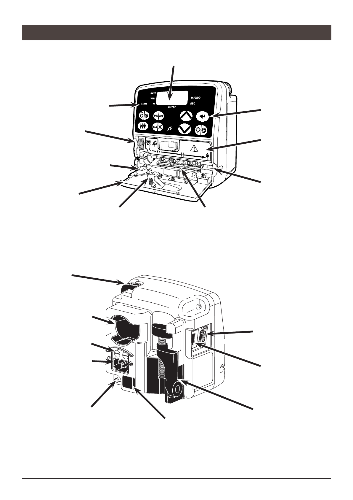
Front view
Display Indicators
Flow Stop Mechanism
When activated the
mechanism will stop fluid
flow.
Air Sensor
Bevel
Releases the flow stop
mechanism lever arm when
the door is closed.
Main Display - Displays the infusion rate, VTBI, VI and time
remaining for VTBI / Time infusions. Display will flash when
pump is operating on battery.
Door Latch
Press outer latch to open
the door.
Tubing Guide
Guide to assist in the loading of
the IV infusion set.
Keypad
Flow Direction Label
Pressure Sensor
Rear view
Release Lever
Rotates cam to release
the pump from horizontal
rectangular bars.
Rotating Cam
Attaches the pump to
rectangular bars or Alaris®
DS Docking Station.
AC Fuses
AC Power Connector
Potential Equalisation (PE)
Connector
RS232 Connector / Nursecall
Flow Sensor Interface
Folded Pole Clamp
Infrared Communications port (IrDA)
Alaris® GW Volumetric Pump 6/77 1000SM00006 Issue 4
Page 7

Controls and indicators
PRIMARY / SECONDARY
Switches the pump between Primary and Secondary infusion modes (if enabled).
ON / OFF
Switches the pump on and off.
PRIME / BOLUS
Primes the IV infusion set.
Administers bolus during the infusion.
CLEAR / SILENCE ALARM
Resets numeric values to zero.
Silences alarms and warnings for 1 minute.
ENTER
Scrolls between rate, time, VTBI and total volume infused (VI).
Enters values for selected infusion/configuration parameters.
Confirms the rate during an infusion titration.
RUN / HOLD
Starts and stops the infusion.
Cancels alarm.
CHEVRONS
Increases or decreases the infusion rate, TIME limit and VTBI.
Press and hold to increase the selection speed.
Used to adjust user selectable options.
Introduction & Start up
When any of the following are illuminated:
AC POWER INDICATOR - The pump is connected to an AC power supply.
RATE The pump is displaying the infusion rate in millilitres per hour (ml/h).
VTBI The pump is displaying the Volume To Be Infused (VTBI) in millilitres (ml).
VI The pump is displaying the Volume Infused (VI) in millilitres (ml).
TIME The pump is displaying the infusion time in hours : mins.
MICRO The pump is operating in the MICRO mode. When not illuminated, the pump is in the STANDARD
mode.
SEC The pump is operating in the SECONDARY mode. When not illuminated, the pump is in the PRIMARY
mode.
ml/hr (Millilitres / hour) When ml is illuminated the pump displays the VTBI or VI. When the hr is illuminated
the pump displays the rate or infusion time.
Infusion indicator - Infusing in STANDARD mode.
Infusion indicator - Infusing in MICRO mode.
Infusion indicator - Displays fluid drops detected by the flow sensor when infusing in STANDARD mode.
Infusion indicator - Displays fluid drops detected by the flow sensor when infusing in MICRO mode.
Alaris® GW Volumetric Pump 7/77 1000SM00006 Issue 4
Page 8

Introduction & Start up
Operating the Alaris® GW Volumetric Pump
Follow the instructions supplied with the individual IV infusion set.
Use of non-specified IV infusion sets may impair the operation of the pump and the
accuracy of the infusion.
Refer to the "Compatible IV Infusion Sets" section in Appendix D, for a list of
recommended IV infusion sets.
Ensure that the tubing is inserted completely into the pumping channel, avoiding any
slack.
Position the IV fluid container to avoid spillage onto the pump.
When using 273-003 IV infusion sets, ensure a separation of at least 30cm is
maintained between the pump and the upper Y-site.
1.
Close the in-line clamp on the IV infusion set. Press the door
latch to open the door.
Release the flow stop mechanism by pushing the lever arm up
2.
and to the right.
3.
Insert the IV infusion set from left to right into the slot provided,
following the flow direction label, avoiding any slack.
Re-engage the flow stop mechanism by pushing the lever left
4.
and down.
Close the door. Use the recesses in the door to press firmly to
5.
ensure the latch is correctly applied. Open in-line clamp on the
IV infusion set.
Observe fluid chamber and check for no fluid flow.
6.
Alaris® GW Volumetric Pump 8/77 1000SM00006 Issue 4
Page 9

Introduction & Start up
Starting the Alaris® GW Volumetric Pump
Close in-line clamp.
1.
Load IV infusion set.
2.
Half fill the drip chamber.
3.
Open in-line clamp.
4.
Press to switch pump on.
5.
Prime () set: Press once. Whilst is displayed press again and hold to clear all visible air from the line.
6.
Connect to test equipment as required.
7.
Set-up pump as described below:
8.
RATE / VOLUME
Enter rate using .
1.
Press once to scroll to VTBI.
2.
Enter VTBI using .
3.
Press to scroll to VI.
4.
If necessary, press to clear VI.
5.
Press to start infusion.
6.
On completion, infusion will continue at KVO rate until is
pressed.
If a flow sensor is used, VTBI is set to
OFF; by pressing the a VTBI may be
set.
Features of the Alaris® GW Volumetric Pump
VTBI / TIME
If necessary, press to put pump on hold.
1.
Press for 2 seconds, press twice and will
2.
display, use Keys to scroll to On.
Press twice to return to hold mode.
3.
Enter VTBI using .
4.
Press to scroll to TIME .
5.
Enter TIME using .
6.
Press to scroll to VI
7.
If necessary, press to clear VI.
8.
Press to start infusion.
9.
Panel Lock - prevents certain key operations
Press together to turn Loc On or to turn Loc Off.
1.
Rate Titration - while infusing
Press to adjust rate.
1.
Press to confirm change of rate.
2.
Bolus Infusions - while infusing
Press twice and hold, release after administering the desired bolus volume.
1.
Micro Mode* - pump must be on hold
Press and hold for 2 seconds.
1.
Press three times - will be displayed.
2.
Use to turn micro mode on or off.
3.
Press once to return to or set-up.
4.
* configurable options, refer to Directions For Use.
Alaris® GW Volumetric Pump 9/77 1000SM00006 Issue 4
Page 10

Chapter 2
Configuration & Calibration
In this chapter
Access codes 11
Configurable options 11
Calibration procedures 13
Page 11
Configuration & Calibration
Configuration & Calibration
Access codes
The pump software contains a number of configuration and test routines that can be accessed by the user. The majority of tests are
driven from a technical access code (see below).
Entering Access Codes
With the pump OFF.
1.
Press and hold and press and release .
2.
The pump will alarm and briefly show the software version
3.
installed in the pump. It will then display “CodE”.
Release the key and the pump will display "0".
4.
Use the keys to select the code required from the list.
5.
Press the key to confirm your choice.
6.
If an invalid code is entered, the pump will display “CodE”
7.
followed by “0”.
Configurable options
The default settings are configurable as displayed in the table below.
Each of the configurable options has a code which must only be altered by a qualified service
engineer with reference to the technical service manual.
Any changes made that are not confirmed by pressing will not be saved on power up.
Use the keys to adjust the selected option. Press the key to confirm your choice. The following access codes can be used to
configure the pump:
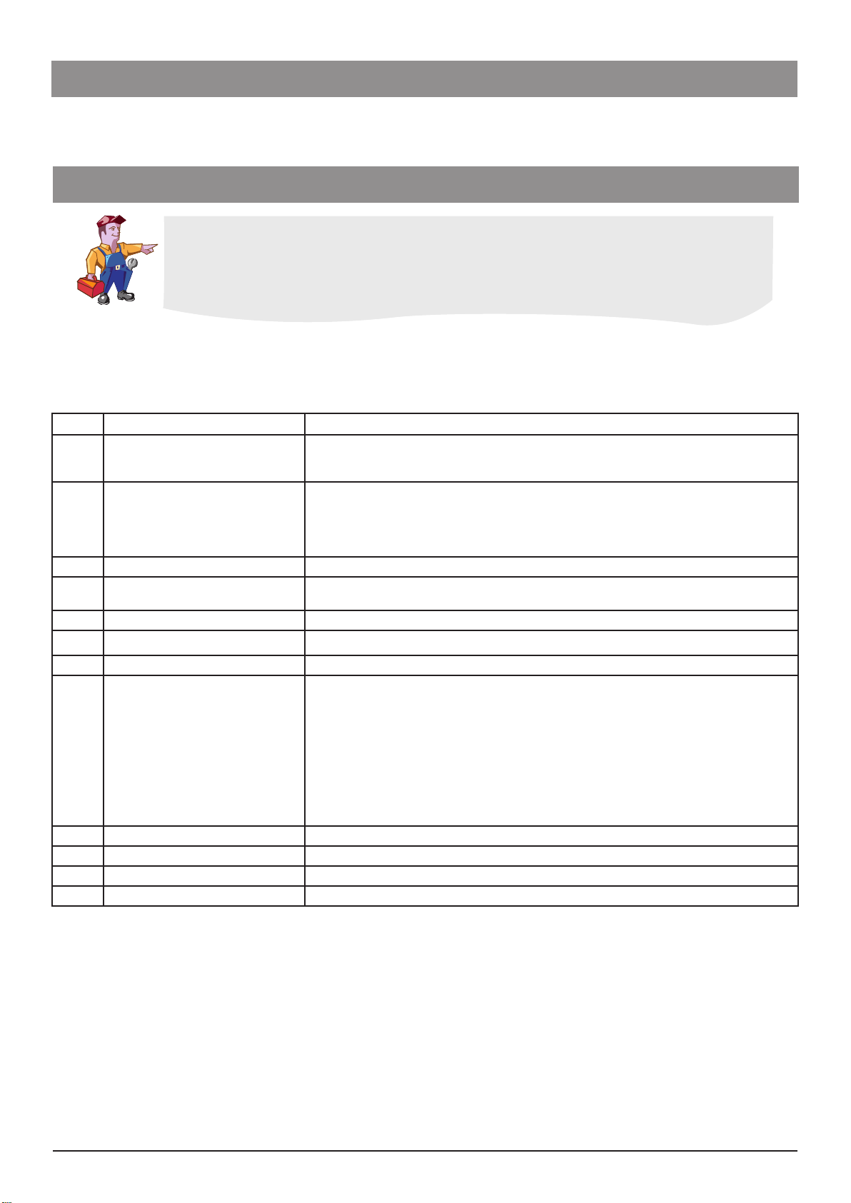
Code Description Default Summary
Select one of the two available infusion modes:
21 Enable Volume/Time Infusions OFF
22 Maximum Priming Volume 40ml
23
24 Maximum VTBI in MICRO Mode 999ml
25 Bolus Rate 400ml/h
26 Maximum Bolus Volume 5ml
27 Keep Vein Open (KVO) Rate 5ml/h
28 Single Bubble Alarm Volume* 100µL
30 Enable Secondary Infusions OFF
31 Default Occlusion Pressure Hi Set the default occlusion alarm value (Lo, Normal or Hi) at power-on.
32 Alarm Volume Level 4 Set alarm volume level between 1 (low) and 7 (high).
35 Enable MICRO Mode OFF
36 Maximum Infusion Rate 999ml/h Set the maximum infusion rate between 1 and 999ml/h.
38 ASCII Mode Comms OFF
Clear Infusion Parameters to Zero
on Power On
OFF
(CLoC) OFF: Input a Flow Rate and Volume to be Infused (VTBI)
(CLoC) ON: Input a Volume to be Infused (VTBI) and Time for infusion.
The Maximum volume (OFF, 1 - 40ml) to be infused during priming
sequence. Before starting an infusion, pressing the b key will initiate set
priming sequence.
OFF: Previous infusion parameters: last rate, VTBI (and time of
infusion if applicable) and volume infused are displayed on
power on.
ON: Previous infusion parameters are reset to zero on power on.
Set the maximum allowable VTBI between 0.1ml and 999ml, in micro
mode only.
Set the Bolus rate between 1 and 999ml/h (providing the default bolus
volume is greater than zero). Pump will infuse at this rate when b key is
pressed twice and held.
Set the maximum bolus volume between Off and 99ml. Maximum
volume that will be delivered whilst the b key is held down during an
infusion.
Set the Keep Vein Open (KVO) rate (OFF, 1.0 - 5.0ml/h). At the end of the
infusion, the pump can either stop pumping or continue infusing at a
Keep Vein Open (KVO) rate.
Set the maximum size of air bubble (50µL, 100µL, 250µL, 500µL) that
can be passed through the pump without causing an alarm.
OFF: Disable automatic secondary infusions.
ON: Enable automatic secondary infusions.
OFF: Standard infusion mode.
ON: Enable micro mode.
OFF: Disable ASCII communications mode.
ON: Enable ASCII communications mode.
Alaris® GW Volumetric Pump 11/77 1000SM00006 Issue 4
Page 12
Configuration & Calibration
Configuration & Calibration
Configurable options (continued)
Code Description Default Summary
39 Odd Parity Comms OFF
40 Pump Address Comms 1 Set pump address used for communications (1 to 250).
41 Flow Sensor Connection Mode AUTO
42 Set-up of Current Time and Date
44 Language Selection EnGL Set language used (EnGL, dEut, FrAn, ItAL, ESPA, nEd, SE).
45 IrDA Communications Selection ON
46 Nurse Call Activation ON
47 Drops per ml of Fluid 20
48 Silent Mode OFF
User Select Mode Configuration:
• Pressure Limit Enabled
49
50 Flow Sensor Sensitivity Level nor
200
201 Reset EEPROM data -
202 Repair EEPROM data -
• Alarm Volume Enabled
• Timed Infusions Enabled
• Micro Infusions Enabled
Reset all configurable options to
default
OFF
- Resets all configurable options to factory default.
OFF: Disable odd communications parity bit generation.
ON: Enable odd communications parity bit generation.
AUTO: Pump automatically detects flow sensor if connected.
ON: Pump will only operate with a flow sensor connected.
Set current time (00:00 to 23:59), and date (01/01/00-31/12/99) for
event logging. Does not automatically adjust for Summer time.
OFF: RS232 comms enabled.
ON: IrDA comms enabled.
OFF: Disable activation state of the nurse call (active low output from
pump).
ON: Enable activation state of the nurse call (active high output
from pump).
Select number of drops per ml of fluid (1 to 200). Defined by the type of
set. Reference the packaging of IV infusion set.
OFF: Audible response to a key press is given.
ON: No audible response to a key press is given.
OFF: Disable mode.
ON: Enable mode.
nor: Normal sensitivity.
Hi: High sensitivity.
Reset EEPROM data code to a defined state if EEPROM checksum error.
NOTE: The pump will need to be returned to factory for reconfiguration
if this option is used.
Detects and repairs any corrupted memory segments, resetting any
repaired areas back to the factory defaults.
NOTE: The pump will need to be returned to factory for reconfiguration
if this option is used.
*Single Bubble Alarm Volume
Although an individual bubble may not exceed the pre-programmed threshold, the
accumulative volume of bubbles, in a 15 minute window, may be sufficient to initiate an air-inline alarm, indicated by an “Air OCCL” message.
Before making any amendments to configuration settings:
Care should be taken to document existing configuration settings to enable changes
to be reverted if required. Configuration requirements may vary from ward to ward
therefore care should be taken to ensure any configuration settings are appropriate
for the ward concerned and users are aware of any changes to configuration settings
prior to use.
Subsequently, sharing of Alaris® GW Volumetric Pumps between wards may be
inappropriate.
Alaris® GW Volumetric Pump 12/77 1000SM00006 Issue 4
Page 13

Configuration & Calibration
Configuration & Calibration
This section outlines the procedures for calibration of the Alaris® GW Volumetric Pump.
All of these calibrations should only be carried out by qualified biomedical engineers. If in any doubt about how to perform the tests,
in particular the pressure sensor calibration checks, contact your local Cardinal Health Service Centre who will be able to assist.
Calibration procedures
Recommended Calibration Equipment
Specialised test equipment is not required for the majority of the functional tests to be carried out on the pump. In order to calibrate
or verify the occlusion alarm point or volumetric accuracy, the following equipment will be necessary:
IV infusion set, suitable for the Alaris® GW Volumetric Pump with standard LUER lock taps for connecting to other test equipment.
If the standard sets are not available, it is possible to order a basic "test set" that is available from your local ALARIS® Service Centre
- part number 0000TG00074. Note that all sets should only be used for a single calibration operation.
Pressure gauge for measuring liquid pressure, with a full scale of 0-2 bar (0-1500mmHg) ±20mmHg.
either:
Class A 50ml glass burette with graduations down to 0.1ml and calibrated down to ± 0.05ml.
or:
Calibrated scales accurate to at least ± 0.01g.
Volumetric Accuracy Calibration (CODE 18)
Volumetric Accuracy Calibration (CODE 18)
The volumetric accuracy calibration routine is used for manufacture of the pump only.
The volumetric accuracy calibration routine is used for manufacture of the pump only.
Displaying the Volumetric and Pressure Calibration Values (CODE 2)
Use of this access code simply displays the calibration values stored in the software.
Enter the access code 2.
1.
Press to step through all Cal values.
2.
Switch the pump "OFF" if there are no further tests to be done at that time.
3.
Battery Calibration (CODE 4)
The pump must be connected to the AC power source throughout the duration of the test. The test can be aborted at any time by
switching the pump off using the key; no change is made to the battery low point calibration value stored previously in the
pump. This calibration should only be performed on a fully charged battery. Ensure the pump is plugged into the mains for at least
24 hours before starting this procedure.
Plug a mains lead into the pump.
1.
Prepare a fluid-filled looped tubing, load it into the pump and close the door.
2.
Enter the access code 4.
3.
The test will start automatically. The pump infuses at 999 ml/h internally switching to the battery power source to discharge the
4.
battery; the air-in-line alarm is disabled. Throughout this test the time indicator will increase in minute intervals.
As soon as the pump detects that the battery is discharged, the time shown on the main display will stop increasing and begin to
5.
flash.
If the time is greater than two hours and the low point voltage value is within the allowable range of 6.5 to 7.8 volts, then the
6.
display shows "PASS" / "xx:xx" / "bx.x", the pass indication, elapsed time and battery low point value in volts. Otherwise the
display shows "FAIL" / "xx:xx" / "bx.x".
Press the key. When the key is pressed, the low point calibration value will be stored.
7.
If the pump is switched off before the key is pressed, the calibration value will be lost and the
If the pump is switched off before the key is pressed, the calibration value will be lost and the
test will have to be repeated. When is pressed, the pump will revert to the technical service
test will have to be repeated. When is pressed, the pump will revert to the technical service
entry mode and flash CodE, followed by 0, this allows you to begin other tests. Switch the pump
entry mode and flash CodE, followed by 0, this allows you to begin other tests. Switch the pump
OFF if there are no further tests to be done at that time.
OFF if there are no further tests to be done at that time.
If the pump fails the calibration, try to charge the battery, and repeat the test. If this fails again then replace the battery and / or
8.
Power Supply Unit.
Alaris® GW Volumetric Pump 13/77 1000SM00006 Issue 4
Page 14
Configuration & Calibration
Configuration & Calibration
Calibration procedures (continued)
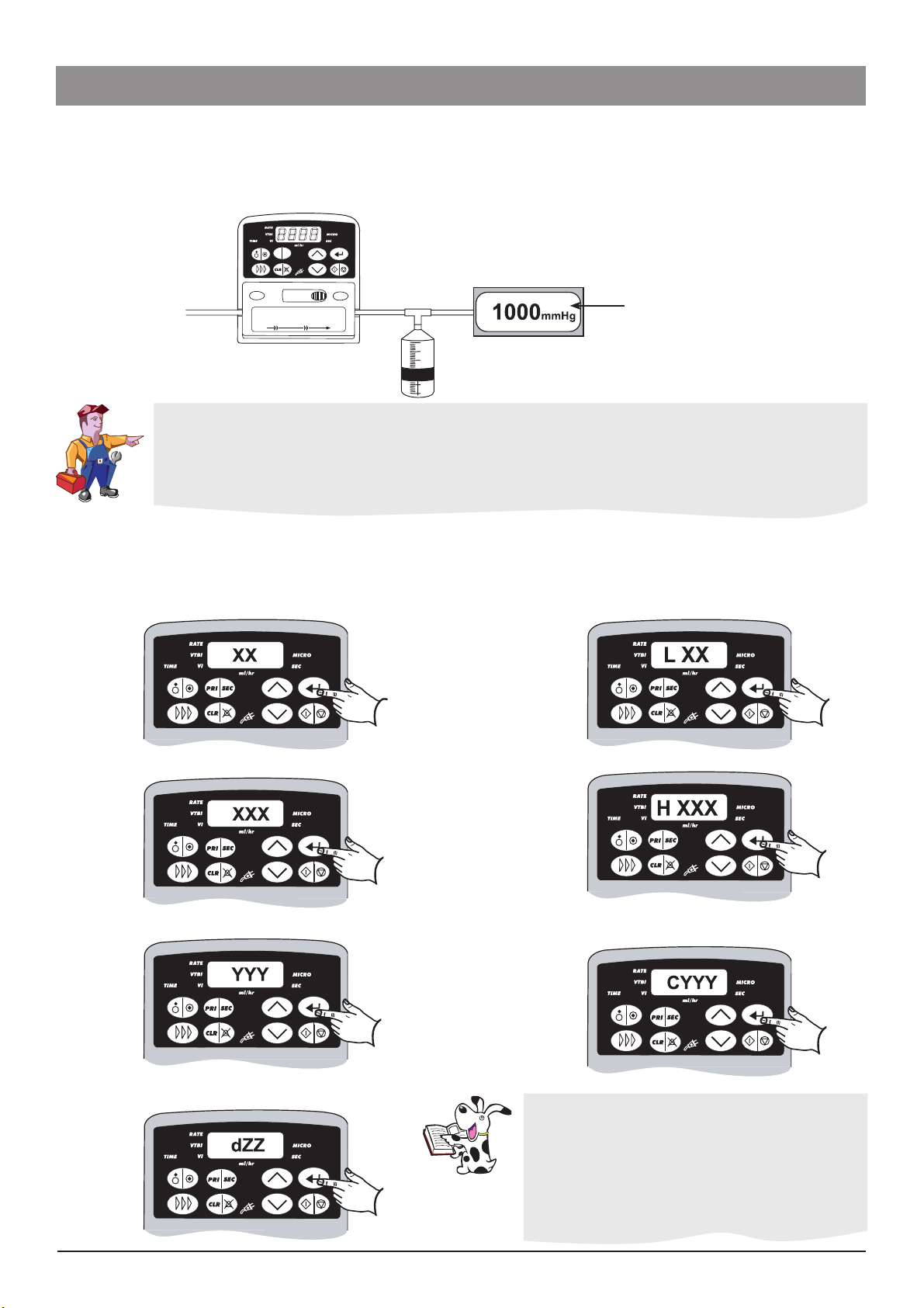
Pressure Sensor Calibration (CODE 17)
An internal pressure sensor is used to detect downstream occlusions. This sensor requires calibration whenever a new sensor, Main
PCB is fitted or if door is changed or removed. It is necessary when servicing a pump, to carry out an occlusion pressure test to verify
that the sensor is calibrated correctly (see self test routine in Chapter 3 Routine Maintenance). A calibrated pressure gauge will be
needed in order to perform this calibration.
PRI
SEC
Pressure gauge
± 20mmHg
When the pressure sensor is replaced the null pressure value must be checked and adjusted, if required, prior to
calibration. Check the null pressure value as follows:
1. Enter the access code 12. Go to test 8 and press e.
2. With no set loaded and door open check displayed value is 11 ±4.
3. If the reading is outside of tolerance then adjust R2 on the Pressure Sensor PCB until displayed value is within
tolerance.
Load a set into the pump to be calibrated and prime the set. Connect to pressure gauge as shown in diagram above.
Enter the access code 17.
Apply pressure required for each step and when pressure required is displayed on pressure gauge for 10 seconds (allows pressure to
settle) press e. Calibration values will be returned. Press e to go to next step.
PrES step - 150mmHg ± 40mmHg
HI step - 650mmHg ± 40mmHg.
CAP step - 1000mmHg ± 40mmHg.
Difference step
XX or XXX indicates calibration values, that have
no tolerance values applicable.
YYY indicates calibration values that should be
between 115 and 214.
ZZ indicates a calibration value that is the
difference between XXX and XX and should be
between 37 and 54.
Alaris® GW Volumetric Pump 14/77 1000SM00006 Issue 4
Page 15

Routine Maintenance
In this chapter
Routine maintenance 16
Test procedures 16
Chapter 3
General cleaning and inspection for damage 20
Storage 20
Data transfer 21
Performance verification procedure 23
Page 16
Routine Maintenance
Routine Maintenance
Routine maintenance
For routine maintenance, the following self-test and performance verification procedures should be performed in addition to the tasks
described in the section on General Cleaning and Inspection for Damage.
Refer to the relevant “Directions for Use” for the recommended routine maintenance period.
Test procedures
Important Service Information:
Important Service Information:
Testing and Calibration of Volumetric pumps is very dependent on the tubing set used.
Testing and Calibration of Volumetric pumps is very dependent on the tubing set used.
For this reason, a new set of tubing should be used for each pump tested, and the tubing
For this reason, a new set of tubing should be used for each pump tested, and the tubing
should be thrown away once all tests are completed. Recommended test set is part number
should be thrown away once all tests are completed. Recommended test set is part number
0000TG00074.
0000TG00074.
Entering Access Codes (Technician Mode)
Note: See Chapter 2 Configuration & Calibration for information on how to enter access codes
Code Test Description
1
2
3 Main Self Test See Self Test Routine Table.
4
5 Volumetric Accuracy Verification Test See Volumetric Accuracy Verification Test (code 5) detailed description in this document.
10 Alarm history log
11 Display current time and date -
12
17 Pressure Calibration Refer to Chapter 2 Configuration & Calibration.
18 Volumetric Calibration This is a manufacturing code, volumetric calibration should not be carried out.
19 Reduced Volumetric Calibration This is a manufacturing code, volumetric calibration should not be carried out.
67 Learn configuration settings See Teach Learn procedure.
Input a pump reference number, and
service date
Display volumetric, pressure
calibration and battery Cal values
Automatic Battery Maintenance/
Discharge Test
Access to individual tests within the
Main Self Test
This enables the user to put in their own 4 digit reference number or asset number, together with
the date the pump was last serviced in the format Wk:Yr (15:01) week 15 of 2001. Defaults to 0 &
0:00.
Reference only, 4 values shown:
CAL - 20.00 if pump has not been calibrated (range 16-24)
Pres - DXXX delta value, (range 36 to 55, default to 46)
CAP - CXXX Maximum value, (range 110 to 219, default 163)
bAt - bx.xx (range 6.44 to 7.86, default 7.15)
Takes approximately 2-5 hours, if it takes less than 2 hours it will display ‘fail’ The pump will then
switch to charging, it is recommended this be done for 24 hours.
This will show the last 10 error/alarm codes Use the key to step through.
Note: Not in Sequential Test (code 3), available only through code 12.
Test Nr. Description
9 EEPROM Checksum Test. Display two 16-bit EEPROM check sums. During power
up the processor calculates EPROM checksums values and checks them against
those stored, if a difference is detected a corruption in data has occurred.
11 Pumping Mechanism Test. This test disables the pressure, door and AIL sensors.
The pump will pump into a pressure gauge and display the pressure reached, this is
exited by pressing the enter key.
12 Bubble Measurement Test. This displays the size of the air bubble detected in
microlitres.
Alaris® GW Volumetric Pump 16/77 1000SM00006 Issue 4
Page 17

Routine Maintenance
Routine Maintenance
Test procedures (continued)
Self test routine
Enter access code 3. Press the key to advance to next test.
Level Test Description
Confirm display indicates correct button pressed.
When level is entered the display will show “b-1”, press buttons 1 to 8, after pressing button 8 the test
will automatically proceed to level 2.
1 Keypad Test
b-1 b-2 b-3 b-4 b-5 b-6 b-7 b-8
Check all LEDs.
The pump will run through a count-up series to illuminate each segment of the 7 segment LEDs, and
2 Display Test
3 Alarm Test
4 Door Test
5 Air Sensor Test
7 Motor Opto Test
8 Occlusion Pressure Test
cycle through all of the green LEDs.
Confirm all LEDs are working. At the end of this test all LEDs will illuminate.
Press the key to advance to level 3.
Confirm the alarm is working and a distinctive change is heard between volume levels. Pump displays
‘ALAR’ and alarms for 0.5 seconds at each volume (1 to 7).
Press the key to advance to level 4.
Confirm the change of state between door open (d-0) and door closed (d-1).
Press the key to advance to level 5.
Confirm the change of state between an air filled set (a-0) and a fluid filled set (a-1).
Press the key to advance to level 7.
Displays PASS or FAIL. Confirm displays PASS. The pump runs the motor forwards a turn, then backwards
a turn. The processor checks that it sees both motor optos come on at the correct time.
Press the key to advance to level 8.
Test requires a calibrated pressure gauge.
Connect the pump IV Infusion set to the pressure gauge via a 3 way tap.
Press the key for 10 seconds. Press the key, the pump will run at 125ml/h and the display will
show the current pressure sensor reading ‘xxx’.
After 10 seconds close off the 3 way tap so that the pump delivers into the pressure gauge.
Confirm that an alarm occurs and a ‘’ appears on the pump display. The pressure displayed on the
pressure gauge should be 500 mmHg +/- 150 mmHg.
Carry out the next test or press the key to advance to level 10.
10 Drop Sensor Test
Check for correct drop count.
This test counts the number of drops detected, if the sensor is not present then ‘Off’ will be displayed.
Alaris® GW Volumetric Pump 17/77 1000SM00006 Issue 4
Page 18
Routine Maintenance
30cm
30cm
30cm
30cm
Routine Maintenance
Test procedures (continued)
Volumetric Accuracy Verification Test (CODE 5)
Important Notes:
Important Notes:
The balances need to be switched on for 30 minutes prior to use to enable the electronics to
The balances need to be switched on for 30 minutes prior to use to enable the electronics to
warm up and settle.
warm up and settle.
Always use new test tubing for each test. If the test ever has to be repeated, a new set of tubing
Always use new test tubing for each test. If the test ever has to be repeated, a new set of tubing
must be used.
must be used.
Do not move the desk during testing, it will upset the balance readings.
Do not move the desk during testing, it will upset the balance readings.
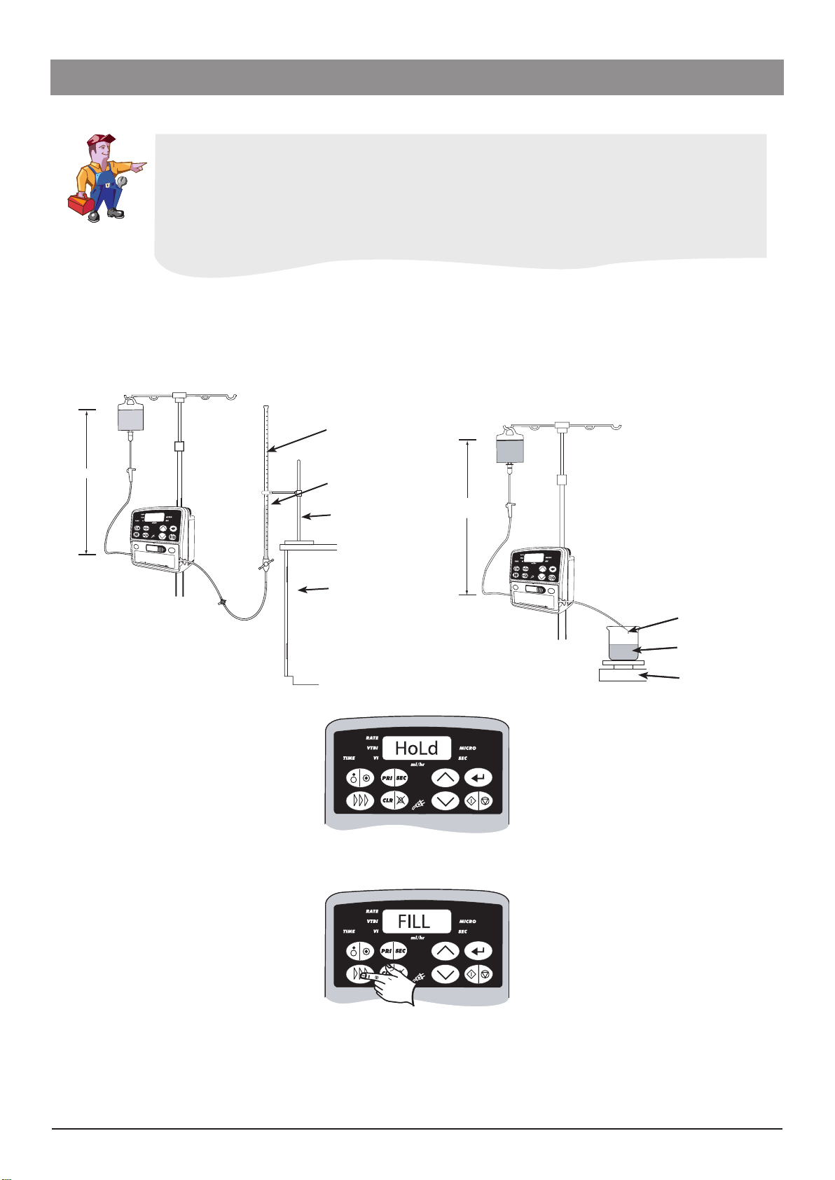
This test is used to confirm that the pumping accuracy of the system as a whole, including the tubing, is within the specified limits.
In the most controlled conditions, a needle should be used to pump liquid into the weighing beaker to prevent liquid touching the
sides of the beaker and to provide some back-pressure so that leaks/overflows do not affect the readings. As a result of these and
other errors, if the system fails just marginally, it is worth performing the test a second time. If it still fails, return the pump to your local
ALARIS® Service Centre for further analysis. The head height on IV infusion set should be approximately 30cm.
Setup A Setup Bor...
Setup A Setup Bor...
Class A Burette (50ml)
Class A Burette (50ml)
0.1ml graduations
0.1ml graduations
Burette clamp
Burette clamp
Equipment stand
Equipment stand
Table or bench
Table or bench
Needle
Needle
Beaker
Beaker
Scales (±0.01g)
Scales (±0.01g)
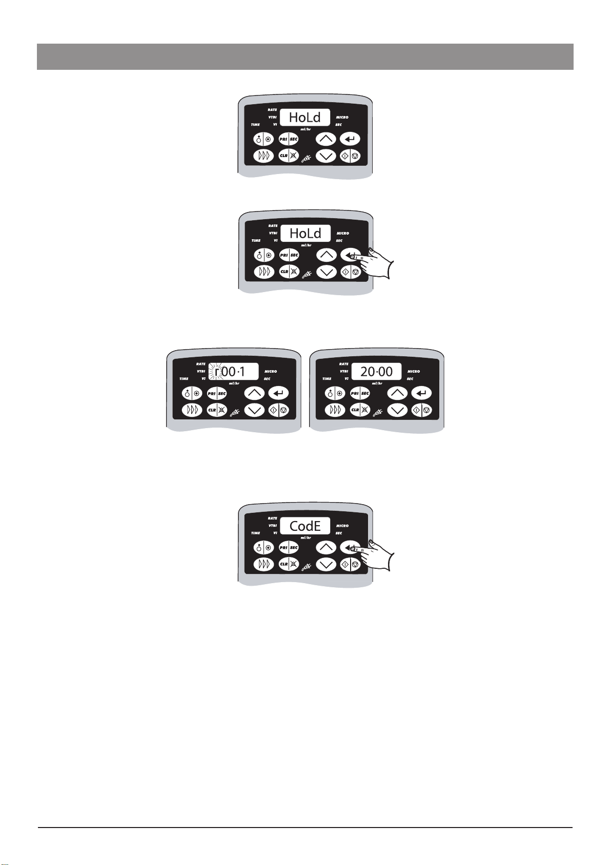
Enter access code 5. The pump will initially display “”.
1.
If it is necessary to prime the set, press and hold the button. The pump will display "" and allow the set to be primed,
2.
ignoring any air-in-line alarms.
Release once the set is primed and the pump will again display “”.
3.
Alaris® GW Volumetric Pump 18/77 1000SM00006 Issue 4
Page 19
Routine Maintenance
Routine Maintenance
Test procedures (continued)
Zero scales or burette. Press to begin the verification check.
4.
The pump will automatically pump at 125ml/h for a total of 20ml, which will take approximately 9½ minutes. During the run, it
5.
will display the volume infused up to that point and intermittently flash "r" with the run indicator, to show that this is a
verification run. At the end of this run, the pump should display "20.00" and “wait”.
Allow the scales to settle and then note the reading on the scales. If using a burette, take the final reading of volume infused.
6.
The volume infused should be 20.00ml ± 5%.
Press the key and the pump will revert to the technical service entry mode and flash "CodE", followed by "0", enabling you to
7.
begin other tests if required. Switch the pump "OFF" if there are no further tests to be done at that time.
Flow Stop Mechanism Test
It is necessary to check that the flow stop device can hold sufficient pressure and thus prevent free flow.
Load set into the pump. Use same setup as for pressure calibration (see Chapter 2 Configuration & Calibration).
1.
Open the door and check that the arm stays in the UP position by lifting the arm onto the ledge.
2.
Close the door fully.
3.
Reopen the door and note that the flow stop arm has activated into the down position.
4.
Pull the test tubing out of the pump and place the tube in front of the flow stop mechanism arm in the down position.
5.
Close the door and reopen the door. Check the tubing locator has loaded the tube fully under the clamp and is flat. This checks
6.
whether the tubing locator is the correct way around and works.
Ensure the door is open and the flow stop is closed. Apply 650mmHg to the distal end of the IV infusion set for 10 seconds. Then
7.
reduce pressure to 500mmHg to the distal end and verify pressure gauge reading is 500mmHg. Ensure the pressure does not
drop by more than 15mmHg in 30 seconds.
Alaris® GW Volumetric Pump 19/77 1000SM00006 Issue 4
Page 20

Routine Maintenance
Routine Maintenance
General cleaning and inspection for damage
To ensure that this pump remains in good operating condition, it is important to keep it clean and carry out the routine procedures
described below. All servicing should only be performed by a qualified service engineer, with reference to this manual.
Thoroughly clean external surfaces of the pump by wiping over with a lint-free cloth, lightly dampened with warm water and a
standard disinfectant/detergent solution.
Do not use the following disinfectant types:
- NaDcc (such as PRESEPT)
- Hypochlorites (such as CHLORASOL)
- Aldehydes (such as CIDEX)
- Cationic Surfactants (such as Benzalkonium Chloride)
- Iodine (such as Betadine)
- Concentrated Isopropyl alcohol based cleaners will degrade plastic parts.
Recommended cleaners are:
Brand Concentration
Hibiscrub 20% (v/v)
Virkon 1% (w/v)
Before cleaning always switch OFF and disconnect from the AC power supply. Never allow liquid
Before cleaning always switch OFF and disconnect from the AC power supply. Never allow liquid
to enter the casing and avoid excess fluid build up on the pump. Do not use aggressive cleaning
to enter the casing and avoid excess fluid build up on the pump. Do not use aggressive cleaning
agents as these may damage the exterior surface of the pump. Do not steam autoclave, ethylene
agents as these may damage the exterior surface of the pump. Do not steam autoclave, ethylene
oxide sterilise or immerse this pump in any fluid.
oxide sterilise or immerse this pump in any fluid.
Labels should be flat and legible. Any label, if no longer fully adhered, must be replaced if it represents a path for fluid ingress.
Case components must be checked for damage that may affect function, fluid ingress route or present a user hazard and be re-
placed if necessary.
Check the pole clamp screws are not loose and that the threads are not damaged. Check that it folds away and ensure arm is not
bent.
Inspect the AC power supply plug and cable for damage.
Clean the flow sensor by wiping over with a cloth, lightly dampened with warm water and a
Clean the flow sensor by wiping over with a cloth, lightly dampened with warm water and a
standard disinfectant/detergent solution. Ensure the connector does not get wet. Dry flow sensor
standard disinfectant/detergent solution. Ensure the connector does not get wet. Dry flow sensor
before use.
before use.
To aid cleaning of flow sensors which have been heavily soiled, contaminated or if handles
To aid cleaning of flow sensors which have been heavily soiled, contaminated or if handles
operation is not free, the flow sensor may be immersed and soaked in clean soapy water.
operation is not free, the flow sensor may be immersed and soaked in clean soapy water.
Activating the spring mechanism of the sensor whilst immersed will assist in cleaning the inside
Activating the spring mechanism of the sensor whilst immersed will assist in cleaning the inside
of the mechanism. After cleaning the sensor should be allowed to dry fully prior to use.
of the mechanism. After cleaning the sensor should be allowed to dry fully prior to use.
Caution: the plug of the sensor should not be immersed as damage will occur.
Caution: the plug of the sensor should not be immersed as damage will occur.
Storage
If the pump is to be stored for an extended period it should be cleaned and the internal battery fully charged. Store in a clean, dry
atmosphere at room temperature and, if available, employ the original packaging for protection.
Once every 3 months during storage, carry out functional tests as described in this chapter and ensure that the internal battery is fully
charged.
Please note during long term storage of the pump the Real Time Clock circuitry is being
Please note during long term storage of the pump the Real Time Clock circuitry is being
maintained by BT1 on the control PCB. Under long term storage conditions it is recommended
maintained by BT1 on the control PCB. Under long term storage conditions it is recommended
that the pump is powered in Technician Mode for a period of 24 hours so as to keep the BT1
that the pump is powered in Technician Mode for a period of 24 hours so as to keep the BT1
charged, and eliminate the possibility of depleting BT1 and inducing Err9 faults at power up.
charged, and eliminate the possibility of depleting BT1 and inducing Err9 faults at power up.
Alaris® GW Volumetric Pump 20/77 1000SM00006 Issue 4
Page 21

Routine Maintenance
Routine Maintenance
Data transfer
Upgrading Software
The optional upgrade of the Alaris® GW Volumetric Pump software to V5R1F should be considered at the next product service for all
Alaris® GW Volumetric Pumps fitted with software version V4R2C. Perform upgrades by acquiring the software upgrade kits specified
in the spares parts listings. Note: when upgrading Alaris® GW Volumetric Pumps from software version V4R1B, first install the V4R2C
software upgrade kit to enable the flash upload capabilty.
The major features of the V5R1F software include:
Teach / Learn Capability;
Additional configuration options:
Silent Mode;
SELECT Mode Options;
Drop Sensor Connection Mode;
Drop Sensor Light Sensitivity Level;
Alarm volume level factory default now 4 (was 7);
Clear Infusion Parameters to Zero default now OFF (was ON).
Additional Technician Mode Configuration options:
New Volumetric Calibration Mode to reduce calibration time (Code 19);
New EEPROM Memory Management to improve work with Teach / Learn and to eliminate need to recalibrate pumps
following firmware upgrade (Codes 200, 201, 202).
Automatic setting of VTBI to OFF when used with drop sensor;
Elimination of '' error in Mode resulting in nuisance alarms;
VI now cleared in Mode and retained upon power down.
Recalibration is not required when upgrading from software version V4R2C, although all configuration parameters will be returned to
factory defaults.
PC Requirements
Microsoft Windows 95, 98, 2000 or NT operating system
9pin D-type PC serial port or IrDA port.
Tools required
CD-ROM 1000SP00493 - Alaris® GW Volumetric Pump Software Distribution Disk V5R1F
Programming Kit 1000SP00172 (Suitable for all ASENA® Infusion Pumps) or RS232 Cable 1000SP00336
Follow the programming instructions given in publication 1000PB01365 (supplied with 1000SP00493).
1.
Load the software program onto your PC from the Distribution Disk.
2.
Select the Alaris LVP SMU icon (WinSmug)
3.
Place the infrared programming device approximately 50mm directly behind the IrDA window on the rear case or connect
4.
the RS232 cable to the 9 pin D type serial port connector situated on the side of the pump.
Select the appropriate port (e.g. COM1) on the Alaris LVP SMU program and Press 'Upload'.
5.
Briefly depress the key on the pump to be upgraded; the pump will now display "PROG".
6.
Switch the pump on for normal operation when the upgrade is complete. If required, the pump will display whilst
7.
automatically completing a test sequence during which the EEPROM memory will be re-partitioned.
When the upgrade is complete, enter the Technician Mode and verify the correct software version has been installed;
8.
initiate a factory Reset (Code 200).
Perform the Self Test checks (Code 3).
9.
Power failure. Power failures may occur when using laptops when communicating with the Alaris®
Power failure. Power failures may occur when using laptops when communicating with the Alaris®
GW Volumetric Pump due to power requirements. External power may be used in conjunction
GW Volumetric Pump due to power requirements. External power may be used in conjunction
with IrDA or RS232 to compensate for lack of power from the laptop.
with IrDA or RS232 to compensate for lack of power from the laptop.
Bright sunlight and strong fluorescent lighting affect the Infrared programming system. If any
Bright sunlight and strong fluorescent lighting affect the Infrared programming system. If any
errors are reported then the RS232 method of upgrading the software should be used.
errors are reported then the RS232 method of upgrading the software should be used.
Alaris® GW Volumetric Pump 21/77 1000SM00006 Issue 4
Page 22

Routine Maintenance
Routine Maintenance
Data transfer (continued)
Teach Learn (Software Versions V5R1F and above)
For both the teach and learn pumps in Technician Mode enable IrDA communications (Code 45), and ensure that ASCII / Binary
1.
mode and parity bit options (Codes 38 and 39 respectively) are the same.
Turn the teaching pump on in normal operation. Note: For multiple teach-learn operations, to avoid call-back alarm every
2.
2 minutes, turn the teaching pump on in Technician Mode.
Enter Technician Code 67 on the learning pump.
3.
Align the two IrDA ports on the pumps (optimum distance 50 mm).
4.
Depress the key to initiate learning.
5.
A progress bar will travel across the learn pump.
6.
When successful, the learn pump will display 'PASS'.
7.
If the learning pump is unable to learn all configuration parameters then the display will show 'ConF' followed by a list of the
8.
configuration parameters that could not be learnt; these will instead contain the factory default settings. This could occur if, for
example, the software version of the learning pump is newer than that of the teaching pump.
Possible Reasons for failure
Possible Reasons for failure
IrDA not enabled on both pumps;
IrDA not enabled on both pumps;
ASCII / Binary and parity bit options are not the same;
ASCII / Binary and parity bit options are not the same;
If the software versions are not compatible;
If the software versions are not compatible;
If the pump models are different;
If the pump models are different;
The line of sight between the IrDA windows was obstructed during data
The line of sight between the IrDA windows was obstructed during data
transfer.
transfer.
Event Log Download
A PC application known as the Event Log Download Utility (ELDU) is available to download the event log from the Alaris® GW
Volumetric Pump.
ELDU Operation
Click on ELDU icon on PC.
1.
Click Accept to agree with Restrictions of Use and continue;
2.
Select Configure from drop-down menu;
3.
Select Setup Pump and choose Alaris® GW as pump type;
4.
Select Settings to select log to be downloaded;
5.
Check communications are set up as follows:
6.
Required PC Comm port selected
Character type and parity match pump configuration
Click OK to confirm
7.
Align the IrDA converter with the IrDA window (optimum distance 50 mm), or connect an RS 232 cable.
8.
Power up the pump by pressing the key.
9.
Click Download log from the main PC screen.
10.
Press Close when finished.
11.
Select File from drop-down menu and save file. Log may be printed here as required.
12.
Alaris® GW Volumetric Pump 22/77 1000SM00006 Issue 4
Page 23
Routine Maintenance
Routine Maintenance
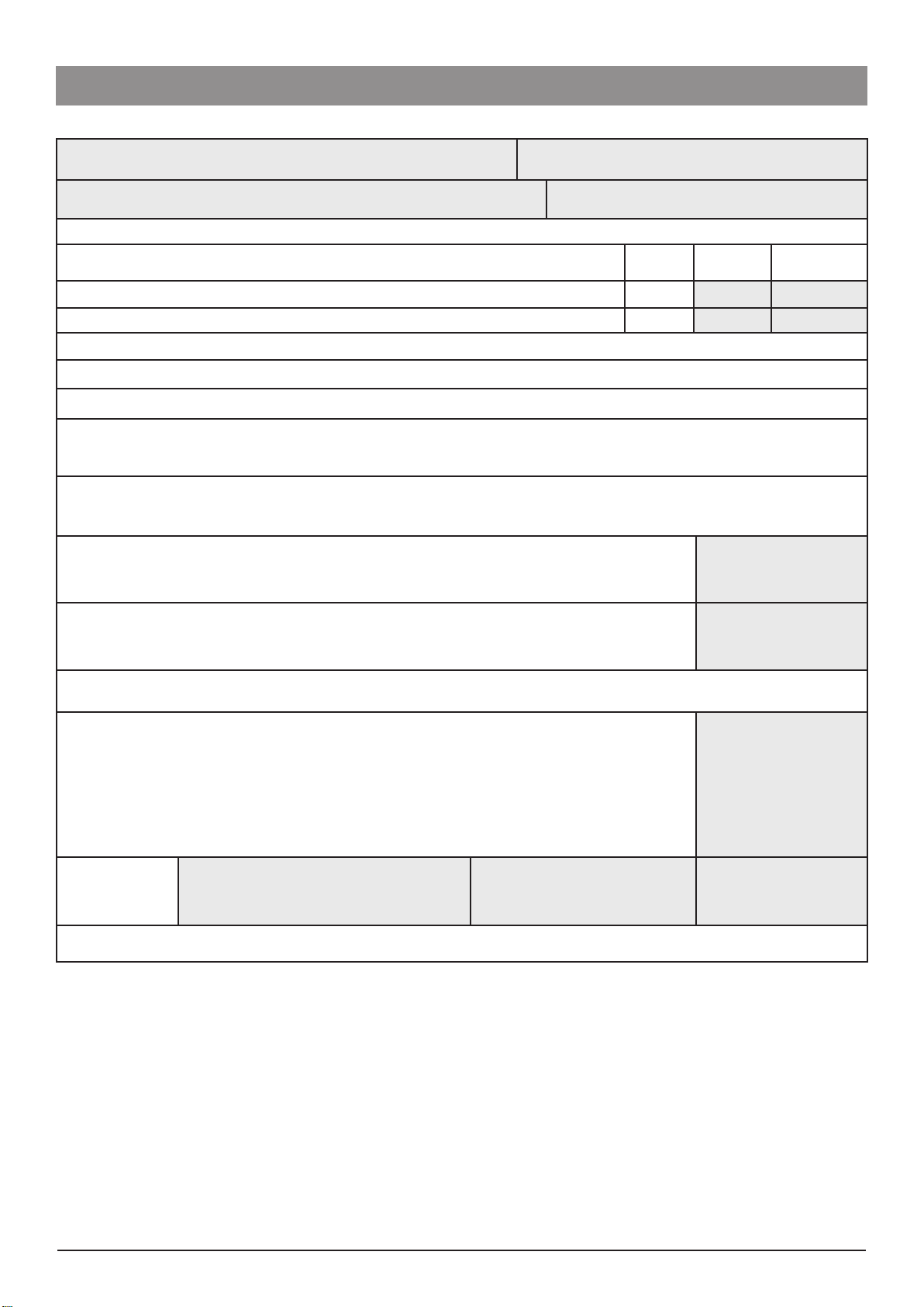
Performance verification procedure
Model / Serial Number: Service Order / Inventory Number:
Hospital Name / Reference: Software Version:
Physical Inspection and Clean
Recommended When Serviced Updates
Grease the pumping mechanism with Molykote PG54. TSM
Upgrade to software version V5R1F or above. TSM
Set/Confirm time and date - access code 42
Set service date - access code 1
Check all functions in Self Test - access code 3
During standard infusion check the following:
KVO Operation
Flow-stop mechanism test
Alarms Functionality Check
Door , AIL (OCC/AIR), Upstream Occlusion (OCC/AIR), Power fail, Time Out, Downstream Occlusion (HI PRESS).
Ensure pump works on battery and AC mains
UPDATE
REF.
Fitted
Not fitted / Not
Applicable
Rate Accuracy Verification Test
(Automatic test in Code 5)
Rate set to 125ml/h, VTBI set to 20ml. Volume infused = 19 to 21ml. _____________ml
Pressure Tests
(Automatic test in Code 12 test 8)
Pump set to alarm at 500mmHg. Pressure = 350 to 650mmHg. _____________mmHg
Set Rate to Zero (or lowest value possible), Clear Volume infused and VTBI
Clear Error/Alarm/Battery logs (As required)
Electrical Safety Test
Class I Type CF
Alternatively attach printed test results
Earth Resistance Test <=0.2 Ω _____________Ω
Earth Leakage Current <=500 µA _____________µA
Enclosure Leakage Current <=100 µA _____________µA
Verification
Performed
By ________________________
Sign
For additional information, refer to:
1000SM00006 - Alaris® GW Volumetric Pump Technical Service Manual (TSM)
_______________________
Print
_________________
Date
Alaris® GW Volumetric Pump 23/77 1000SM00006 Issue 4
Page 24

Troubleshooting
In this chapter
Software alarm codes & displayed messages 25
Alarm types 27
Chapter 4
General fault diagnosis 27
Page 25

Troubleshooting
Troubleshooting
Software alarm codes & displayed messages
Note: The alarm codes are intended only for fault finding and diagnostic purposes and are therefore not displayed directly to the
user. The alarm history log stores the last ten alarm codes in a “first in, first out” sequence once the maximum ten codes have been
exceeded.
Display
Attn
boL A bolus is being administered. boL display replaced with a volume counter during infusion.
ErrA - N
Errb - N Fatal micro-controller failure.
End Indicates end of infusion. Re-program the VTBI to resume infusion.
Err 1 N Motor controller is out of bounds.
bAt 2 N
Lo bAt
Air OCCL 3 R Upstream occlusion/air-in-line. Check AIL sensor function.
HI PrES 4 R
HoLd Indicates the pump is on hold. Audible alarm after 2 minutes.
door 5 R Door is open whilst pump is infusing. Check door magnet or sensor is flat against case.
bAd SEt 6 R
Err 7 N Pressure sensor failure.
Err 8 N Power failure on AC power.
Err 9 N Safety circuit supply failure.
Err 10 N
Err 11 N
Err 12 N
Err 13 N
Err 15 N Micro-controller stack overflow. Replace Control PCB.
Err 16 N
Err 19 N Hardware initiated motor brake.
Err 20 N No. of encoder revolutions too high.
Alarm
Code
Type Description Troubleshooting Guide
The pump has been left unattended
for 2 minutes and the infusion has not
started.
Communications failure with external
memory.
Internal battery depleted /
disconnected.
Battery voltage threshold of 7v
reached. approximately 30 minutes of
running time left.
Downstream occlusion IV line
pressure exceeds limit threshold.
IV set used fails automatic set test
(incorrectly loaded).
Motor is idle at very low infusion
rates.
Motor controller drive voltage limit
exceeded.
Incorrect number of encoder steps/
revolutions.
Encoder rotation time incorrect for
set rate.
Communication failure with external
real time clock (RTC).
Press to temporarily silence for 1 minute.
Replace the Control PCB.
Replace the Control PCB. If pump does not subsequently
power up, replace the pressure sensor / encoder assembly.
Check the mechanical parts around the gears / encoder for
obstructions.
Charge pump for 12 hours, check mains, battery fuses and
battery.
Charge pump for 12 hours, check mains, battery fuses and
battery.
Check pressure and recalibrate.
Check the function of the pressure sensor.
Replace pressure sensor/encoder assembly. If error recurs,
replace the Control PCB.
Check cables around the power connector to Control PCB.
Ensure battery is connected. Check PSU Comms PCB and
replace if necessary. If error recurs replace Control PCB.
Ensure JP12 is firmly connected. Check voltage on realtime clock battery. If low, power-up in technician mode to
recharge whilst connected to AC mains. If problem persists,
replace the Control PCB.
Check around the motor assembly, check for loose wires.
Check for mechanical obstruction around the gear area.
Check cabling to motor. Apply grease to pumping finger
cams as per Chapter 6. Replace the pressure sensor / encoder
assembly, if necessary. If error recurs, replace the Control PCB.
Check for damaged/distorted motor encoder wheel. Replace
the pressure sensor/encoder assembly, if necessary. If error
recurs, replace the Control PCB.
Withdraw the pump from service and ensure it is inspected
by a qualified service engineer.
Replace Control PCB.
Replace Control PCB. If error recurs, replace the pressure
sensor/encoder assembly.
Withdraw the pump from service and ensure it is inspected
by a qualified service engineer.
Alaris® GW Volumetric Pump 25/77 1000SM00006 Issue 4
Page 26

Troubleshooting
Troubleshooting
Software alarm codes & displayed messages (continued)
Display
Err 21 N No. of encoder revolutions too low.
Err 24 N Time base difference.
Err 28 N Watchdog timeout. Replace the Control PCB.
Err 29 N Keypad failure.
Err 30 N Calibration data out of bounds.
Err 31 N External memory checksum Replace the Control PCB.
Err 32 N Software execution error. Replace the Control PCB.
FLo SEnS 33 R Flow sensor error.
FLo Err 34 R
Err 35 N Pump not calibrated.
Err 36 N
Err 38 N 7-segment LED display failure. Replace the Control PCB.
Err 39 N Audible alarm failure. Check cable to speaker. Replace the Control PCB if necessary.
Err 40 N Critical variable corruption. Replace the Control PCB.
Err 41 N State invariant corruption. Replace the Control PCB.
Err 42 N ADC out of range. Replace the Control PCB.
Loc On/Loc
oFF
Sec
Fill Pump priming IV infusion set.
Alarm
Code
Type Description Troubleshooting Guide
Withdraw the pump from service and ensure it is inspected
by a qualified service engineer.
Ensure JP12 is firmly connected. Replace the Control PCB if
necessary.
One or more of the keypad switches on the Control PCB is
faulty. Replace the Control PCB. Note: may also be caused by
pressing an invalid key during power-up. If this case, there is
no fault.
Reset pump with code 200 and recalibrate. Replace the
Control PCB if necessary.
Occurs if flow sensor is connected or disconnected whilst
pump is infusing, or if the flow sensor is disconnected and
the VTBI is off.
Flow error. Gross over / under
infusions, bag empty, or flow
detected when not infusing.
Logic error (invalid RTC data update
during infusion).
Indicates keypad panel locked/
unlocked.
Pump is running in secondary
operation mode.
Check set, fluid and correct loading. Check flow sensor and
connection to pump.
If a new Control PCB is fitted, calibrate pressure and
battery and perform a volumetric verification accuracy test.
Otherwise, withdraw the pump from service and ensure it is
inspected by a qualified service engineer.
Replace the Control PCB.
Activate/deactivate by pressing o for two seconds.
Key:
N : Non Recoverable Alarm
R : Recoverable Alarm
Alaris® GW Volumetric Pump 26/77 1000SM00006 Issue 4
Page 27

Troubleshooting
Troubleshooting
Alarm types
Non Recoverable Alarms
In this state the pump will stop the infusion and give an audible and visible warning to alert the user that a non recoverable
alarm (registered on the pump as a Fatal alarm) has occurred. With the exception of a micro-controller (MCU) error or internal
communications fault with the external EEPROM, each alarm condition is identified by a unique code, which is stored in the alarm
history log each time an alarm occurs, to enable the qualified service engineer to trace the error condition. From a non recoverable
alarm the user is able only to enter the POWER DOWN mode. The non recoverable conditions are defined in the alarm code table.
Recoverable Alarms
In this state the pump stops the infusion and gives an audible and visible warning to alert the user to the alarm condition, and to
provide an indication of the nature of the alarm. Each alarm is identified by a unique code, which is stored in the alarm history log each
time an alarm occurs to enable the technician to trace the alarm condition.
The recoverable alarms are defined in the alarm code table. After a recoverable alarm has occurred, the pump responds only to the
following three actions: the user may temporarily silence the alarm for one minute by depressing the key; this action will suspend
only the audible indicator, with the visual message remaining. After one minute the audible indicator will return.
The pump may be switched off directly from the ALARM mode by depressing and holding the key, to initiate the power down
sequence. If the power down sequence is not completed, then the pump immediately returns to the ALARM mode and initiates the
audible alarm.
To return the pump to the “HoLd” mode, the user presses the key; this action clears the alarm message on the main display and
silences the audible indicator.
General fault diagnosis
Dropped or damaged
Exposed to fluids
No battery power
General Fault
No AC mains power
Parts to Check/Test
Front Case
Rear Case
Labels
Mechanism
Control PCB
Power PCB
Battery
Mains Lead
Fuses
Delivery rates out of
tolerance
Alaris® GW Volumetric Pump 27/77 1000SM00006 Issue 4
Page 28

Circuit Descriptions
In this chapter
Module overview functional description 29
Control Board 29
Chapter 5
Power Supply Unit and Communications Board 30
Pressure Sensor and Encoder Board 30
Functional module block diagram 31
Page 29

Circuit Descriptions
Circuit Descriptions
Module overview functional description
The pump is designed to be serviced generally to major assembly level. The PCBs are designed as non-serviceable items and as such,
can only be replaced as complete parts.
Cardinal Health will make available, on request, circuit diagrams, which will assist appropriately qualified technical personnel to repair
those parts of the pump which are designated by the manufacturer as repairable.
The main circuitry within the Alaris® GW Volumetric Pump is contained on three printed circuits boards - Control PCB, Power Supply
and Communications PCB, and a small Pressure Sensor and Encoder PCB and additional plug in sensors.
Control Board
Microcontroller Block
All control and display functions are controlled by this part. Safety functions are spread around the pump with various parts. The
controller is supported by a watchdog and power reset circuit. An EEPROM is used to store logged data for the pump. There is a
battery backed real-time clock.
Power Control Block
Raw DC power is connected from the Power Supply unit to JP1 connector. In the event of the raw DC exceeding 36 volts, components
form a crowbar. Components form a 12 volt Switch Mode Power Supply (SMPS). Components form a 12-volt monitor circuit for the
Microcontroller. The battery is connected to pin 3 of JP1 and is constantly charged when connected to the mains. Components form
a 5-volt reference voltage to the main processor. A switch mode regulator supplies 5-volts (VCC) to the pump. There are two 5-volt
crowbar protection circuits.
Motor Driver
A Microcontroller I/O is used to control the motor speed. The modulated signal is smoothed to a DC voltage appropriate to control
motor speed. Relay 1 is used to reverse the voltage applied to the motor. This reversal is used for some modes of operation. Safety
devices stop the motor if necessary.
User Interface
Microcontroller drives the seven segment displays and the LEDs. The keyboard is scanned for key depressions .The display currents are
monitored. Time division multiplexing enables complete control of a user interface display and input with the Microcontroller.
Air-in-line sensor
A phase shift oscillator drives the Air-in-Line sensor; the output of the phase shift oscillator signal is fed into a voltage controlled
oscillator. The signal is transmitted through the fluid filled tubing and received by the ultrasonic sensor. The received signal is then
passed through a window detector and then to a level detector and input into the Microcontroller.
Air-in-Line
Two ultrasonic transducers continuously check for the presence of air in the IV infusion set throughout the infusion. This air-in-line
feature operates in two modes:
Single Bubble Detection - The pump will alarm and display Air OCCL whenever a single air bubble greater than the air-in-line volume
alarm limit is detected. The alarm limit can be configured to 50, 100, 250 or 500µl. See also “Configurable Options” section of Chapter 2.
Air-in-Line Accumulation - This accumulation feature monitors the volume of air that passes through the IV infusion set by
accumulating the volume of individual bubbles over a 15 minute window. The accumulation will alarm if more than 500µL of air is
registered. This feature is particularly useful with infusions for patients that are highly sensitive to air (i.e., neonates, paediatrics) or
when infusing products that create significant volumes of small air bubbles.
Flow sensor
The flow sensor is input into the Main Processor.
Door sensor
A Hall effect sensor detects if the door is open or closed and a Microcontroller reads the state of the sensor.
Buzzer
The Microcontroller is used to switch on the alarm (buzzer).
Audio Alarm
The input to the Audio alarm section is driven by a signal from the Microcontroller, fed into a phase shift oscillator and through an RC
network to remove any DC present on the signal. The signal is amplified and drives the speaker.
Alaris® GW Volumetric Pump 29/77 1000SM00006 Issue 4
Page 30

Circuit Descriptions
Circuit Descriptions
Power Supply Unit and Communications Board
Power module
The selection of 115V or 230V is made via S1. The secondary is rectified to an unregulated DC Voltage. F2 is a Polyswitch resetable fuse.
The raw DC is output to the Control PCB. The battery is connected via JP3, the maximum current being limited by F1.
RS232 & Nursecall
The external RS232 connection is made via JP5 where power for the 4kV isolated interface is taken from pins 4 and 7. This voltage is
converted to a 5-volt supply and in turn converts the RS232 communications levels to TTL which are then sent to the Microcontroller.
The Nursecall interface is controlled from the Microcontroller to energise the relay which causes the contact to change over.
IrDA Module
IrDA or RS232 is selectable. The IrDA communication signal is output from IC7.
Pressure Sensor and Encoder Board
Motor encoder
Diodes D1 and D2 are the emitters in the motor encoder and OPT1 and OPT2 being the receivers. The signals are sent to the Control
PCB where they are used in conjunction with the Pressure Sensor and Encoder PCB to provide a quadrature detection scheme from the
rotary encoder on the drive motor. These signals are then processed via the Microcontroller.
Pressure sensor
The strain gauge is connected to the Pressure Sensor PCB, the sensor o/p signal is then amplified and then output to the Control PCB
and used to provide a second stage of amplification for the pressure sensor signal. This signal is processed via the Microcontroller.
Alaris® GW Volumetric Pump 30/77 1000SM00006 Issue 4
Page 31

Circuit Descriptions
Circuit Descriptions
Functional module block diagram
Control PCB
Key
Switches
(Includes motor encoders)
Pressure Sensor PCB
Pressure
Sensor
JP10
Air
Sensor
(Door)
Air Sensor
(Front panel)
Audible
Alarm
JP5
JP11JP8 JP9
Door
Sensor
Display
LEDs
Air
Sensors
Audible
Alarm
Motor
Encoders
Motor
Control
Safety
Backup
Main Processor
Backup
Speaker
JP3
Pumping
Block
Flow Sensor
Programming
Connection Box
RS232/
Nursecall
Connector
JP5
Flow
Sensor
Programming
Comms
IrDA
Backup
Battery
Comms
JP6
Power
Distribution
Power
Module
PSU & Comms PCB
JP1
JP2JP4
JP1
JP3
AC Mains
Inlet
Battery
Alaris® GW Volumetric Pump 31/77 1000SM00006 Issue 4
Page 32

Chapter 5
Spare Parts Replacement Procedures
In this chapter
Separation of front and rear cases 33
Front case assembly 34
Door assembly 35
Pumping block assembly 36
Air sensor assemblies 37
Pressure sensor assembly 38
Flow-stop assembly 39
Control PCB 40
Rear case assembly 41
Battery 42
PSU & Comms PCB 43
Speaker 44
Rear case connectors 45
Rear Case Rail Cam Mechanism 46
Mains inlet 47
PE Stud and Pole Clamp 48
Labels 49
Page 33

Spare Parts Replacement Procedures
Separation of front and rear cases
These instructions apply only to the Alaris® GW Volumetric Pumps. Ensure the pump is disconnected
from AC power supply and switched off before attempting to service the pump.
The pump contains static-sensitive components. Observe strict precautions for the protection of staticsensitive components when attempting to service and repair the pump. As a minimum, carry out all
servicing on a workbench with a static dissapative surface and wear a grounded wrist strap.
Ensure that all test and calibration procedures are carried out as recommended in the service manual
after any component fitting.
For fastener torque settings, refer to Appendix C Fitting & Replacement Guidelines.
For additional technical assistance, contact your local Cardinal Health Service Centre.
Remove the 4 corner screws, which secure the rear case to the front case.
1.
For many subsequent operations it is possible to make all repairs with the two halves still joined, however to disassemble the two
2.
halves completely:
(a) Disconnect the four-way cable assembly that links the PSU and Comms PCB with the Control PCB.
(b) Unplug the 8-way connector from the Control PCB.
(c) Unplug the flow sensor cable and the speaker cable.
(d) Remove screw, collect washer and remove the earth connection from the Pumping block.
Reassemble in reverse order.
3.
Flow sensor cable
Earth cable
Speaker cable
8-way cable
Corner screws (x4)
4-way cable
Description Part Number Description Part Number
ASENA GW, KIT, FRONT CASE 230V GERMAN 1000SP00343 ASENA GW, KIT, REAR CASE 230V SWEDISH 1000SP00325
ASENA GW, KIT, FRONT CASE 230V SPANISH 1000SP00333 ASENA GW, KIT, REAR CASE 230V NORWEGIAN 1000SP00368
ASENA GW, KIT, FRONT CASE 230V FRENCH 1000SP00331 ASENA GW, KIT, REAR CASE 230V DUTCH 1000SP00340
ASENA GW, KIT, FRONT CASE 230V ENGLISH 1000SP00252 ASENA GW, KIT, REAR CASE 230V ITALIAN 1000SP00323
ASENA GW, KIT, FRONT CASE 110V ENGLISH 1000SP00327 ASENA GW, KIT, REAR CASE 110V ENGLISH 1000SP00326
ASENA GW, KIT, FRONT CASE 230V ITALIAN 1000SP00332 ASENA GW, KIT, REAR CASE 230V ENGLISH 1000SP00261
ASENA GW, KIT, FRONT CASE 230V DUTCH 1000SP00344 ASENA GW, KIT, REAR CASE 230V GERMAN 1000SP00339
ASENA GW, KIT, FIXINGS (SCREWS,WASHERS,ETC) 1000SP00489 ASENA GW, KIT, REAR CASE 230V SPANISH 1000SP00324
ASENA GW, KIT, FRONT CASE 230V 1000SP00334 ASENA GW, KIT, REAR CASE 230V FRENCH 1000SP00322
SWEDISH/NORWEGIAN
Alaris® GW Volumetric Pump 33/77 1000SM00006 Issue 4
Page 34

Spare Parts Replacement Procedures
Front case assembly
In order to replace a front case, it will be necessary to fully strip down the old case and insert all of the components into the new
1.
front case. The task requires a good knowledge of the pump, so be certain that you are fully conversant with all of the procedures
in this section before undertaking this replacement. In order to simplify the task, new front cases are supplied with the flow stop
mechanism, air sensors, and the finger and pressure sensor covers already fitted, so it is not necessary to remove these from the
old case.
For each sub-assembly to be stripped down, follow the instructions in the relevant section of this manual. The recommended
2.
order for stripping down a front case is described below :
Separate the front and rear case halves;
Remove the Control PCB;
Remove the door assembly;
Remove the Pumping block assembly (keeping the motor on the chassis);
Remove the pressure sensor.
When re-assembling these sub-assemblies into the new case, it is advisable to simply reverse the order of dis-assembly.
3.
It will also be necessary to apply a new front panel label, door label and flow direction label at the
end of assembly. These labels are language specific. Refer to the “Spare Parts Listing” in this service
manual to ensure that you order the correct label set. The part number should also be shown on the
labels that were removed from the old case.
Write the serial number of the pump on the label provided and stick it onto the inside of the new
case.
Alaris® GW Volumetric Pump 34/77 1000SM00006 Issue 4
Page 35

Spare Parts Replacement Procedures
Door assembly
Remove the air sensor assembly from the back of the door and retain the small screws for re-assembly later.
1.
Remove circlips and push out the two shafts that form the hinge of the door so that they clear the first part of the hinge.
2.
Do not free the main pressure plate that is sprung on the door.
The old door assembly will now come free from the front of the pump.
3.
Reassemble in reverse order.
4.
When fitting the door, take care to keep the air sensor on the correct side of the door
and do not crush its wires.
(A) Door magnet
(C) Circlips (x2)
(B) Door assembly
(C) Screws (x2)
Air sensor
Item Description Part Number
A MAGNET DOOR 1000ME01151
B ASENA GW, KIT, DOOR 1000SP00253
C ASENA GW, KIT, FIXINGS(SCREWS,WASHERS,ETC) 1000SP00489
Alaris® GW Volumetric Pump 35/77 1000SM00006 Issue 4
Page 36

Pumping block assembly
Spare Parts Replacement Procedures
Unplug the motor wiring loom from the Control
1.
PCB in the front case.
Remove the flow direction indication label from
2.
the front of the pump.
(D) Strip finger
(E) Fixing screws (x4)
Washers (x2)
(C) Motor wiring loom
Pumping fingers
(A/B) Pumping block assembly
Unscrew the four screws, collect two washers that secure the pumping block to the front case, two of which are located behind
3.
the label and two that are near the door hinge.
It should now be possible to push out the pumping block and completely separate it from the front case. When doing this, take
4.
care not to lose any of the pumping fingers, or copper finger strip, which will be free to fall out when the main chassis is removed.
Retain all of them for re-assembly later.
Reassemble in reverse order. Tighten the countersunk screws first, then the pan head screws. Ensure the pumping fingers are
5.
the correct way around with the narrow curved end in contact with the tubing. Fit a new flow direction label to the front of the
pump.
IMPORTANT: Recommended when serviced, grease should be applied a minimum of once every 12
months.
The Alaris® GW Volumetric Pump uses Molykote grease (F) to lubricate the moving mechanical
parts of the pumping mechanism to reduce the current draw of the pump. Only Molykote PG54
grease has been approved as compatible with the pump components. Each of the cams should
have a thin layer applied to the circumference so that the fingers run smoothly over the cam face.
The grease can be applied by a lint-free cloth or finger for example, to achieve an even layer over
each cam.
Item Description Part Number
A ASENA GW, KIT, PUMP BLOCK 230V 1000SP00257
B ASENA GW, KIT, PUMP BLOCK 110V 1000SP00329
C ASENA GW, ASSY, MOTOR WIRING LOOM 1000SP01077
D ASENA GW, ASSY, STRIP FINGER (Be Cu) 0000EL00816
E ASENA GW, KIT, FIXINGS(SCREWS,WASHERS,ETC) 1000SP00489
F ASENA GW SPARES KIT MOLYKOTE GREASE 1000SP00469
Alaris® GW Volumetric Pump 36/77 1000SM00006 Issue 4
Page 37

Spare Parts Replacement Procedures
Air sensor assemblies
1. Unplug the four-way connector for the two air sensors.
2. Unscrew the door air sensor from the back of the door and pull out the two wires through the hole to free the sensor.
(A) Front panel air sensor
(A) Door air sensor
3. Carefully push out the front panel air sensor, while moving the three retaining lugs towards the centre of the sensor, by
pressing gently on the encapsulated area with a screwdriver. Again, pull the two wires free from the front case.
4. Reassemble in reverse order.
4-way connector
Rear of front panel air sensor mounting
(A) Front panel air sensor
(A) Door air sensor
The two air sensors are similar, but can easily be distinguished. The door sensor has a flange
with two countersunk holes in it. The front panel sensor has three sprung clips to hold it in
the case.
Insert the crimps into the four-way connector provided, as indicated by the following
diagram:
Pin 1 Door Sensor White
Pin 2 Door Sensor White
Pin 3 Front Panel Sensor Blue
Pin 4 Front Panel Sensor Blue
1 2 3 4
Item Description Part Number
A ASENA GW, KIT, AIR SENSORS 1000SP00265
Alaris® GW Volumetric Pump 37/77 1000SM00006 Issue 4
Page 38

Spare Parts Replacement Procedures
Pressure sensor assembly
Remove the three screws that hold the pressure sensor assembly in place. Unplug the assembly from the Control PCB. Carefully
1.
remove the pressure sensor from the case.
Reassemble in reverse order. Tighten the larger 2 screws first, then the smaller screw.
2.
(C) Backstop
(D) Screws (x3)
Side View
Underside View
(A or B) Pressure sensor and encoder assembly
Item Description Part Number
A ASENA GW, KIT, PRESSURE SENSOR 230V 1000SP00256
B ASENA GW, KIT, PRESSURE SENSOR 110V 1000SP00330
C ASENA GW, ASSY, BACKSTOP/MEMBRANE CLAMP 1000ME01592
D ASENA GW, KIT, FIXINGS(SCREWS,WASHERS,ETC) 1000SP00489
Alaris® GW Volumetric Pump 38/77 1000SM00006 Issue 4
Page 39

Spare Parts Replacement Procedures
Flow-stop assembly
Remove the flow direction label to reveal one of the screws holding the flow-stop assembly. Remove the two screws that hold
1.
the flow-stop housing mechanism onto the front case and remove the whole assembly as a single item. This includes the sprung
arm and the small cover that provides the locking position for the arm.
Assemble a new flow-stop mechanism (see instructions below), if required.
2.
Reassemble in reverse order.
3.
(A or B) Flow-stop
housing
Fitting a new flow-stop mechanism
New flow-stop mechanisms are provided as a kit of parts,
1.
so it will be necessary to assemble the mechanism prior
to fitting. Use the old mechanism that has been removed
as a guide to this process and if necessary refer to the
assembly drawings shown here.
Insert the flow-stop clamp into the flow stop housing
2.
and align the holes and secure them together with the
pinching arm shaft and star fastener.
Insert the spring through the hole in the flow-stop
3.
housing. Locate the opposite end of the spring on the tag
on the flow-stop clamp.
Fit the flow-stop cover over the top of the assembly and
4.
then refit the whole assembly back in position in the case,
so that the pinch-point of the flow-stop clamp fits through
the lower of the two holes.
The flow-stop mechanism (Items A or B)
Pinching arm shaft
Flow-stop cover
Flow-stop clamp
Spring
Flow-stop housing
Star fastener
Item Description Part Number
A ASENA GW, KIT, FLOWSTOP MECHANISM 230V 1000SP00254
B ASENA GW, KIT, FLOWSTOP MECHANISM 110V 1000SP00328
Alaris® GW Volumetric Pump 39/77 1000SM00006 Issue 4
Page 40

Spare Parts Replacement Procedures
Control PCB
Removal of the Control PCB
Unplug all of the connectors that plug into the Control PCB - i.e. the pressure sensor, the air sensors and the motor wiring loom,
1.
as well as the main linking cable to the rear case.
Remove the two securing screws and two washers that hold in the Control PCB and remove the PCB from the front case.
2.
Reassemble in reverse order.
3.
(B) Control PCB fixing screws (x2)
(A) Control PCB
Item Description Part Number
A ASENA GW, ASSY, CONTROL PCB 1000EL00347
B ASENA GW, KIT, FIXINGS(SCREWS,WASHERS,ETC) 1000SP00489
Alaris® GW Volumetric Pump 40/77 1000SM00006 Issue 4
Page 41

Spare Parts Replacement Procedures
Rear case assembly
In order to replace a rear case, it will be necessary to fully strip down the old case and insert all of the components into the
1.
new rear case. The task requires a good knowledge of the product, so be certain that you are fully conversant with all of the
procedures in this section before undertaking this replacement.
For each sub-assembly to be stripped down, follow the instructions in the relevant section of this manual. The recommended
2.
order for stripping down a rear case is described below :
Separate the front and rear case halves;
Remove the PSU and Comms. PCB;
Remove the pole clamp;
Remove battery.
The mains inlet assembly is very difficult to remove, so a new assembly is provided with the new rear case and the old one will
3.
have to be discarded with the old rear case.
When re-assembling these sub-assemblies into the new case, it is advisable to simply reverse the order of dis-assembly.
4.
Having re-assembled all of the sub-assemblies described above, plug the mains inlet assembly into the PSU and Comms. PCB.
5.
Secure the earth cable onto the pumping block with the screw and shakeproof washer.
It is necessary to apply a new alarm code label and back panel label (with serial number
It is necessary to apply a new alarm code label and back panel label (with serial number
and voltage information) at the end of assembly. These labels are language and pump
and voltage information) at the end of assembly. These labels are language and pump
specific.
specific.
Write the serial number and build issue of the pump on the two labels provided. Stick
Write the serial number and build issue of the pump on the two labels provided. Stick
the larger one behind the window in the new back panel label and fix the second onto
the larger one behind the window in the new back panel label and fix the second onto
the back of the new case.
the back of the new case.
Finally re-assemble the pump.
6.
Mains fuse replacement
Unplug the pump from all mains power and unscrew the fuse holders from the mains inlet.
Replace the fuses as follows:
230V pump - 63mA anti-surge (T rated) fuses (0000EL00287)
115V pump - 125mA anti-surge (T rated) fuses (0000EL00288)
Battery fuse replacement
Unplug the mains inlet and battery from the Power Supply PCB and remove the PCB from the
rear case. Unsolder the blown Pico fuse (F1) and replace with a new one of the following type:
1A Pico fuse (0000EL00809)
Alaris® GW Volumetric Pump 41/77 1000SM00006 Issue 4
Page 42

Spare Parts Replacement Procedures
Battery
It is recommended that the battery is replaced at least every 3 years, in order to
guarantee maximum backup battery time.
Remove the small plastic clamp and clip that holds the battery in place. Unplug the battery from the PSU and Comms.
1.
PCB and remove the battery from the rear case.
Re-assemble in reverse order.
2.
(A) Battery clamp
(C) Battery pack
(B) Battery clip
Item Description Part Number
A ASENA GW, ASSY, BATTERY CLAMP 1000ME00379
B ASENA GW, ASSY, BATTERY CLIP 1000ME01481
C BATTERY PACK NiMh FUSED ASENA GW 1000EL00349
Alaris® GW Volumetric Pump 42/77 1000SM00006 Issue 4
Page 43

Spare Parts Replacement Procedures
PSU & Comms PCB
Unplug the mains inlet, the battery and the 4-way cable assembly from the PSU and Comms. PCB and 8-way connector and flow
1.
sensor connector.
Remove the four securing screws that hold in the PCB and remove the PCB from the rear case.
2.
Reassemble in reverse order.
3.
(D) Screws (x4)
(C) 4-way cable assembly
(B) Serial comms cable
(A) PSU
Flow sensor and speaker cables have been removed for clarity.
Power supply kit (1000SP00427) includes new RS232 connector and battery
clamp, as previous parts are not compatible with new PSU. Replace RS232
connector and battery clamp if required.
Item Description Part Number
A ASENA GW, KIT, POWER SUPPLY UNIT (PSU) 1000SP00427
B ASENA GW, ASSY, SERIAL COMMS CABLE 1000SP01135
C ASSY CABLE 4 WAY 1000SP01076
D ASENA GW, KIT, FIXINGS(SCREWS,WASHERS,ETC) 1000SP00489
Alaris® GW Volumetric Pump 43/77 1000SM00006 Issue 4
Page 44

Speaker
Remove or replace insulator or speaker as required.1.
Spare Parts Replacement Procedures
(B) Insulator
(A) Speaker
Item Description Part Number
A ASSY SPEAKER ALARM P8000 1000SP00099
B INSULATOR ASENA GW 1000ME01429
Alaris® GW Volumetric Pump 44/77 1000SM00006 Issue 4
Page 45

Spare Parts Replacement Procedures
Rear case connectors
1.
Remove RS232 connector.
2.
Remove screws holding Flow Sensor Clamp and remove clamp.
Remove Flow Sensor connector.
3.
Reassemble in reverse order.
4.
(A)
(G)
(B)
(C)
(D)
(H)
(E)
(F)
Item Description Part Number
A ASENA GW, ASSY, DROP SENSOR CABLE 1000SP01133
B ASENA ASSY, KIT, RS232 CABLE 1000SP00336
C ASENA GW, KIT, FIXINGS(SCREWS,WASHERS,ETC) 1000SP00489
D ASENA GW, ASSY, DROP SENSOR CLAMP 1000ME01402
E ASENA GW, ASSY, COVER DUST DROP SENSOR 1000ME00291
F ASENA GW, ASSY, COVER DUST RS232 0000ME00444
G STUD SHOULDER M3 RS232 1000ME01362
H GASKET RS232 P8000 1000ME01300
I ASENA GW, KIT, FIXINGS(SCREWS,WASHERS,ETC) 1000SP00489
(I)
Alaris® GW Volumetric Pump 45/77 1000SM00006 Issue 4
Page 46

Spare Parts Replacement Procedures
Rear Case Rail Cam Mechanism
Assemble rail cam internal mechanism as per diagrams below.
1.
Remove and replace cam rail components as required.
2.
Reassemble in reverse order.
3.
(C)
(D)
Stage 1
(A)
(G)
Stage 2
(B)
(C)
(H) Seal ring
(I) Cam rail clamp
(E)
(F)
Item Description Part Number
A LINKING ASENA GW 1000ME01401
B LEVER RAIL CAM INTERNAL 1000ME01205
C ASENA GW, KIT, FIXINGS(SCREWS,WASHERS,ETC) 1000SP00489
D SPRING RAIL CAM P8000 0000ME00419
E LEVER RELEASE RAIL CLAMP 1000ME01203
F SEAL RING V 6MM DIA 0000ME00381
G LEVER PUMP RELEASE MACHINED 1000SP00241
H SEAL RING V 10MM DIA 0000ME00380
I CAM RAIL CLAMP 1000ME01187
Alaris® GW Volumetric Pump 46/77 1000SM00006 Issue 4
Page 47

Mains inlet
Spare Parts Replacement Procedures
Remove 2 screws securing Mains inlet and retainer.
1.
Remove Mains inlet and retainer.
2.
Remove magnet.
3.
Reassemble in reverse order.
4.
(D)
(E)
(C)
(A) Mains inlet assembly
Magnet (item D) can be held in place with a plastic
covered proximity magnet placed over IR window.
Magnet will be held in place with mains inlet retainer
(item B).
(B)
Item Description Part Number
A ASENA GW, ASSY, MAINS INLET 1000SP01134
B ASENA GW, ASSY, MAINS INLET RETAINER 1000ME01443
C GASKET MAINS INLET 1000ME01299
D MAGNET IR DETECT 1000ME01303
E ASENA GW, KIT, FIXINGS(SCREWS,WASHERS,ETC) 1000SP00489
Alaris® GW Volumetric Pump 47/77 1000SM00006 Issue 4
Page 48

Spare Parts Replacement Procedures
PE Stud and Pole Clamp
1.
Remove nut securing earth wire.
Remove nut securing PE Stud.
2.
Remove the three screws and remove the pole clamp assembly.
3.
Reassemble in reverse order.
4.
(C) Fixing screws (x3)
(A)
(D) Label protective earth
(A)
(A)
(A) PE stud
(B) Pole clamp assembly
A modified Knob Pole Clamp screw has been designed which incorporates a metal tip added to its
end. This amendment has increased the holding friction of the Pole Clamp assembly on the pole and
reduced the amount of tightening required to grip the pole.
The Pole Clamp Arm spares kit replaces parts of the Pole Clamp assembly to address bent or slipping
pole clamps. Note: There is no requirement to remove the V Clamp.
V Clamp (remains fixed to the
pump case).
Arm clamp
Modified Knob Pole
Clamp Screw.
(E)
Item Description Part Number
A ASENA SP, KIT, PE STUD 1000SP00467
B ASENA SP, ASSY, POLE CLAMP 1000SP00115
C ASENA GW, KIT, FIXINGS(SCREWS,WASHERS,ETC) 1000SP00489
D LABEL PROTECTIVE EARTH 1000LB00292
E SPARES KIT POLE CLAMP ARM 1000SP00589
F POLE CLAMP SNAKE EYE DRIVER (not shown) 1000ME01466
G Spare pole clamp arm kit asena sp/gw 1000SP00589
Apply small amount of Castrol LMX
grease to this surface.
Spring
Ball Bearing
Pivot Screw (Torque to 2Nm
using Driver)
(G)
Apply Loctite 242 &
Loctite 7471 here.
Alaris® GW Volumetric Pump 48/77 1000SM00006 Issue 4
Page 49

Labels
Spare Parts Replacement Procedures
A3
A2
A1
A1
A4
A2
A3
A4
Item Description Part Number
A ASENA GW, LBL, LABEL SET (240V) UNIVERSAL 1000LB00371
A ASENA GW, LBL, LABEL SET (110V) UNIVERSAL 1000LB00384
B LABEL PROTECTIVE EARTH (x2) 1000LB00292
Item B not shown - located on pumping block and inside rear case.
Alaris® GW Volumetric Pump 49/77 1000SM00006 Issue 4
Page 50

Labels (continued)
Spare Parts Replacement Procedures
A
After fitting label, verify all LEDs are fully visible at their correct locations.
A
English language sample shown. See
parts list below for language specific
options.
Item Description Part Number
A ASENA GW, LBL, FRONT PANEL ENGLISH 1000LB00251
A ASENA GW, LBL, FRONT PANEL FRENCH 1000LB00287
A ASENA GW, LBL, FRONT PANEL ITALIAN 1000LB00288
A ASENA GW, LBL, FRONT PANEL GERMAN 1000LB00290
A ASENA GW, LBL, FRONT PANEL SPANISH 1000LB00291
A ASENA GW, LBL, FRONT PANEL DUTCH 1000LB00389
A ASENA GW, LBL, FRONT PANEL SWEDISH 1000LB00393
Alaris® GW Volumetric Pump 50/77 1000SM00006 Issue 4
Page 51

Labels (continued)
Spare Parts Replacement Procedures
A
A
English language sample shown.
See parts list below for language
specific options.
Item Description Part Number
A ASENA GW, LBL, ALARM ENGLISH 1000LB00374
A ASENA GW, LBL, ALARM GERMAN 1000LB00386
A ASENA GW, LBL, ALARM FRENCH 1000LB00396
A ASENA GW, LBL, ALARM ITALIAN 1000LB00397
A ASENA GW, LBL, ALARM SPANISH 1000LB00398
A ASENA GW, LBL, ALARM SWEDISH 1000LB00399
A ASENA GW, LBL, ALARM DUTCH 1000LB00400
A ASENA GW, LBL, ALARM PORTUGESE 1000LB00420
Alaris® GW Volumetric Pump 51/77 1000SM00006 Issue 4
Page 52

Specifications
In this appendix
Electrical 53
Appendix A
Environmental 53
Infusion 53
System accuracy 54
General specifications 54
Recycling 55
Electromagnetic Compatibility 56
Page 53

Specifications
Specifications
Electrical
Class I Equipment
Type CF Equipment (degree of protection
against electrical shock)
Electrical Safety Complies with EN60601-1-1 (IEC601-1) and EN60601-2-24 (IEC601-2-24).
Electromagnetic compatibility (EMC) Complies with EN60601-1-2 and EN60601-2-24.
Electrical safety EN60601-1 (IEC 601-1) - typical earth leakage current 40µA.
Dielectric strength Proof strength test 1.5kV dc (live and neutral to earth).
Performance strength test 500V dc (live and neutral to earth).
AC power supply 115 VAC, 50/60Hz, 10VA (nominal).
230 VAC, 50/60Hz, 10VA (nominal).
Battery power supply Rechargeable NiMH (Nickel Metal Hydride). Automatically charges when the
Alaris® GW Volumetric Pump is connected to AC power.
Battery life >6 hours @ 25 ml/h, >4 hours @ 125 ml/h, >2 hours @ 999 ml/h with new, fully
charged cells with no loss of infusion accuracy; measured with 95% percentage
population / 95% confidence interval.
Battery charging 95% charge - < 24 hours (all conditions).
Environmental
Operating limits Min Max
Temperature +15°C +38°C
Humidity 20% 90%*
Atmospheric pressure 700mbar 1060mbar
Transport limits Min Max
Temperature -20°C +50°C
Humidity 10% 95%*
Atmospheric pressure 500mbar 1060mbar
IPX rating IPX 1
Infusion
Priming the IV infusion set / Prime
Parameter Range
Priming rate Fixed; >999ml/h
Priming volume 0 - 40ml***
Starting the infusion / set-up
Infusion parameter Micro Standard
Flow rate 1.0ml/h - 99.9ml/h** 1ml/h - 999ml/h***
VTBI 0.1ml - 99.9ml** 1ml - 9999ml***
100ml - 999ml***
VI 0.0ml - 99.9ml** 0ml - 9999ml***
100ml - 9999ml***
Administering a Bolus
Parameter Range
Bolus rate 1 - 999ml/h***
Bolus volume 0 - 99ml***
Max bolus volume after <0.6ml
release of hard occlusion.
*Non condensing.
**Measured in 0.1ml increments.
***Measured in 1ml increments.
Alaris® GW Volumetric Pump 53/77 1000SM00006 Issue 4
Page 54

System accuracy
Specifications
Specifications
Rate Accuracy
±5% at 25 ml/h under nominal conditions
Tested to EN60601-2-24 (90% confidence interval / 95% population).
2
Bolus Volume Accuracy
±10% @ 5ml under nominal conditions2
Tested to EN60601-2-24.
Under all conditions3 the bolus volume accuracy should be de-rated as for rate accuracy.
Occlusion Pressure Accuracy
±150 mmHg under nominal conditions2
±250 mmHg under all conditions
3
Air in Line Accuracy
±20% or ±0.025ml5 under nominal conditions2
Notes:
All accuracy specifications are with a 95% confidence interval / 95%
1.
population, unless stated otherwise.
Nominal conditions are defined as:
2.
Set Rate: 125 ml/h (25 ml/h for rate accuracy);
Disposable Type: ALARIS® Infusion Set (Model 273-001);
Needle: 18 gauge x 40 mm;
Solution Type: De-ionised & Degassed Water;
Temperature: 23° ± 2°C
Fluid Head Height: 0.3 ± 0.1 m; Back Pressure: 0 ± 10 mmHg.
All conditions are as nominal conditions with the following additions
3.
Set Rate: 1 to 999 ml/h;
Solution Type: All fluids (see note 4);
Temperature: 15 to 38°C
Fluid Head Height: 0 ± 1.0 m;
Tested using Distilled water, 20% lipid, 50% glucose, 5% Normal Saline
4.
and 5% Alcohol solutions.
Whichever is the greater of the air in line limit set.
5.
For all conditions the rate accuracy should be adjusted by the
6.
following percentages:
± 10% over the infusion rate range 1 to 999 ml/h
Nominal: -2.5 (± 1.81)% over 8 hours of continuous use.
Nominal: -3.5 (± 1.08)% @ 15°C
Nominal: -0.9 (± 0.62)% @ 38°C
General specifications
Alarm conditions
System error Upstream occlusion
Air-in-line Incorrect IV set
Battery depleted Door open
Downstream occlusion
Critical volume
KVO infusion rate Up to a maximum of 5ml/h or the infusion rate if programmed less than the set KVO
rate.
Occlusion pressure
250mmHg (low).
350mmHg (normal).
500mmHg (high).
Fuse type
2 X T 63 mA, slow blowing (230V).
Air sensor
Air in line detector Single bubble:
Accumulator:
The maximum volume infused following a single fault condition is 1.0ml.
User selectable: occlusion alarm pressure at 125ml/h:
2 X T 125 mA, slow blowing (115V).
Integral ultrasonic sensor.
Configurable 50µl, 100µl, 250µl, 500µl.
Fixed 500µl
Total time setting
Up to 99 hours and 59 mins.
Memory retention The electronic memory of the pump will be retained for more than 6 months when
not powered up.
Alaris® GW Volumetric Pump 54/77 1000SM00006 Issue 4
Page 55

Specifications
Specifications
General specifications (continued)
Calibration units of measure The units of measurement used in the calibration procedure are:
1. Millilitres (ml) volume of fluid.
2. Millilitres per hour (ml/h) for volumetric flow rate.
3. Millimetres of mercury (mmHg) or KpA for pressure.
4. Hours:minutes (h:min) for time.
5. Volts (V) for battery voltage.
Dimensions
Weight: 1.5kg (excluding power cable).
137mm (w) x 140mm (h) x 105mm (d).
Recycling
Disposal of Alaris® GW Volumetric Pump components:
Follow local governing ordinances and recycling instructions regarding disposal or recycling of pump components, including batteries.
Alaris® GW Volumetric Pump 55/77 1000SM00006 Issue 4
Page 56

Specifications
Electromagnetic Compatibility
Warning:
• The use of any accessory, transducer, or cable with the Alaris® GW Volumetric Pump other than those specified may result in
increased emissions or decreased immunity of the pump.
• The Alaris® GW Volumetric Pump should not be used adjacent to or stacked with other equipment and that is adjacent or stacked
use is necessary, the Alaris® GW Volumetric Pump should be observed to verify normal operation in the configuration in which it
will be used.
Caution:
• The Alaris® GW Volumetric Pump is a CISPR 11 Group 1 Class A Medical Equipment System and intended for use by healthcare
professionals only.
• Medical Electrical Equipment needs special precautions regarding EMC and needs to be installed, put into service and used
according to the EMC information provided in the accompanying documents.
• Portable and Mobile RF communications can affect Medical Electrical Equipment.
• Operating the pump near equipment which radiates high energy radio frequencies (electro surgical or cauterizing equipment,
portable radios, cellular telephones, etc.) may cause false alarm conditions. If this happens, reposition the pump away from the
source of interference or turn off the pump and manually regulate the flow.
Guidance and Manufacturer’s Declaration – Electromagnetic Emissions
The Alaris® GW Volumetric Pump is intended for use in the electromagnetic environment specified below.
The customer or the user of the Alaris® GW Volumetric Pump should assure that it is used in such an environment.
Emissions Test Compliance Electromagnetic Environment – Guidance
CISPR 11
RF Emissions
CISPR 11
RF Emissions
EN 61000-3-2
Harmonic Emissions
EN 61000-3-3
Voltage Fluctuations,
Flicker Emissions
Group 1
Class A
Class A
Complies
The pump uses RF energy only for its internal function in the normal product
offering. Therefore, its RF emissions are very low and are not likely to cause any
interface in nearby electronic equipment.
The pump is suitable for use in all establishments, other than domestic, and
those directly connected to the public low-voltage power supply network that
supplies buildings used for domestic purposes.
Alaris® GW Volumetric Pump 56/77 1000SM00006 Issue 4
Page 57

Specifications
Electromagnetic Compatibility (continued)
Guidance and Manufacturer’s Declaration - Electromagnetic Immunity
The Alaris® GW Volumetric Pump is intended for use in the electromagnetic environment specified below.
The customer or the user of the Alaris® GW Volumetric Pump should assure that it is used in such an environment.
Immunity Test
EN 60601-1-2
Test Level
Compliance Level Electromagnetic Environment – Guidance
EN 61000-4-2
Discharge (ESD)
EN 61000-4-4
Electrical Fast Transient, Burst
(EFT) (Note 3)
EN 61000-4-5
Power Line Surge
(Note 3)
EN 61000-4-8 Power
Frequency Magnetic Field
(50/60 Hz)
Electro-Static
±6 kV contact
±8 kV air
±2 kV for power
supply lines
±1 kV for input/
output lines
±1 kV Line(s) to
Line(s)
±2 kV Line(s) to
Earth
3 A/m 400 A/m 50 Hz
±8 kV contact
(Note 2)
±15 kV air (Note 2)
±2 kV for power
supply lines
N/A (Note 4)
±1 kV Line(s) to
Line(s)
±2 kV Line(s) to Earth
(Note 2)
Floors should be wood, concrete, or ceramic tile.
If floors are covered with synthetic material, the
relative humidity should be at least 30 %.
If connector testing exemption is used, the following
symbol for ESD sensitivity appears adjacent to each
connector. “Caution – Do Not Touch”.
Mains power quality should be that of a typical
commercial or hospital environment.
Mains power quality should be that of a typical
commercial or hospital environment.
Power frequency magnetic fields should be at
levels characteristic of a typical location in a typical
commercial or hospital environment.
EN 61000-4-11
Voltage Dips, Short
Interruptions, and Voltage
Variations
(Note 3)
Note 1—UT is the AC mains voltage prior to application of the test level.
Note 2—Compliance levels raised by EN 60601-2-24.
Note 3—Performed at the Minimum and Maximum Rated Input Voltage.
Note 4—Cardinal Health recommends using signal cables of less than 3 meters in length and this requirement is applicable only if signal cables are 3
meters or more in length. (EN 60601-1-2:2002, Clause 36.202.4)
<5 % UT (Note 1)
(>95 % dip in UT)
for 0.5 cycle
40 % UT
(60 % dip in UT)
for 5 cycles
70 % UT
(30 % dip in UT)
for 25 cycles
<5 % UT
(>95 % dip in UT)
for 5 sec
<5 % UT
(>95 % dip in UT)
for 0.5 cycle
40 % UT
(60 % dip in UT)
for 5 cycles
70 % UT
(30 % dip in UT)
for 25 cycles
<5 % UT
(>95 % dip in UT)
for 5 sec
Mains power quality should be that of a typical
commercial or hospital environment.
If the user of the pump requires continued
operation during power mains interruptions, it is
recommended that the pump be powered from an
uninterruptible power supply or a battery.
The pump does employ an internal short duration
battery.
Alaris® GW Volumetric Pump 57/77 1000SM00006 Issue 4
Page 58

Specifications
Electromagnetic Compatibility (continued)
Guidance and Manufacturer’s Declaration—Electromagnetic Immunity
LIFE SUPPORT Equipment
The Alaris® GW Volumetric Pump is intended for use in the electromagnetic environment specified below.
The customer or the user of the Alaris® GW Volumetric Pump should ensure that it is used in such an environment.
Immunity Test
EN 61000-4-6
Conducted RF
EN 61000-4-3
Radiated RF
EN 60601-1-2
Test Level
3 V rms
150 kHz to 80
MHz
3 V/m
80 MHz to 2.5 GHz
Compliance
Level
10 V rms
(Note 3)
10 V/m
(Note 3)
Electromagnetic Environment – Guidance
Portable and mobile RF communications equipment should be used no
closer to any part of the pump, including cables, than the recommended
separation distance calculated from the equation applicable to the frequency
of the transmitter.
Recommended Separation Distance
3.5
d = [-----] √P
V
1
12
d = [-----] √P 80 MHz to 800 MHz
V
2
12
d = [-----] √P 80 MHz to 2.5 GHz
E
1
23
d = [-----] √P 800 MHz to 2.5 GHz
E
1
where P is the maximum output power rating of the transmitter in watts
(W) according to the transmitter manufacturer and d is the recommended
separation distance in meters (m).
a
Field strengths from fixed RF transmitters, as determined by an
electromagnetic site survey, b should be less than the compliance level in
each frequency range.
c
Interference may occur in the vicinity of equipment marked with the
following symbol:
Note 1—At 80 MHz and 800 MHz, the higher frequency range applies.
Note 2—These guidelines may not apply in all situations. Electromagnetic propagation is affected by absorption and reflection from structures, objects,
and people.
Note 3—Compliance levels raised by EN 60601-2-24.
a The compliance levels in the ISM frequency bands between 150 kHz and 80 MHz and in the frequency range 80 MHz to 2.5 GHz are intended to
decrease the likelihood that mobile/portable communications equipment could cause interference if it is inadvertently brought into patient areas. For
this reason, an additional factor of 10/3 is used in calculating the recommended separation distance for transmitters in these frequency ranges.
b Field strengths from fixed transmitters, such as base stations for radio (cellular/cordless) telephones and land mobile radios, amateur radio, AM and
FM radio broadcast, and TV broadcast cannot be predicted theoretically with accuracy. To assess the electromagnetic environment due to fixed RF
transmitters, an electromagnetic site survey should be considered. If the measured field strength in the location in which the pump is used exceeds
the applicable RF compliance level above, the pump should be observed to verify normal operation. If abnormal performance is observed, additional
measures may be necessary, such as re-orienting or relocating the pump.
c Over the frequency range 150 kHz to 80 MHz, field strengths should be less than 10 V/m.
Alaris® GW Volumetric Pump 58/77 1000SM00006 Issue 4
Page 59

Specifications
Electromagnetic Compatibility (continued)
Recommended Separation Distances for LIFE SUPPORT Equipment between
portable and mobile RF communications equipment and the Alaris® GW Volumetric Pump
The Alaris® GW Volumetric Pump is intended for use in an electromagnetic environment in which radiated RF disturbances
are controlled.
The user of the Alaris® GW Volumetric Pump can help prevent electromagnetic interference by maintaining a minimum distance
between portable and mobile RF communications equipment (transmitters) and the Alaris® GW Volumetric Pump as recommended
below, according to the maximum output power of the communications equipment.
Separation Distance According to Frequency of Transmitter
Rated Maximum Output
Power of Transmitter
W
150 kHz to 80 MHz
Outside ISM bands
3.5
d = [------] √P
V1
150 kHz to 80 MHz
In ISM bands
12
d = [------] √P
V2
m
80 MHz to 800 MHz
12
d = [ ------] √P
E1
800 MHz to 2.5 GHz
23
d = [------] √P
E1
0.01
0.1
1
10
100
For transmitters rated at a maximum output power not listed above, the recommended separation distance d in meters (m) can be determined using the
equation applicable to the frequency of the transmitter, where P is the maximum output power rating of the transmitter in watts (W) according to the
transmitter manufacturer.
Note 1—At 80 MHz and 800 MHz, the separation distance for the higher frequency range apply.
Note 2—The ISM (Industrial, Scientific, and Medical) bands between 150 kHz and 80 MHz are 6.765 MHz to 6.795 MHz; 13.553 MHz to 13.567 MHz; 26.957
MHz to 27.283 MHz; and 40.66 MHz to 40.70 MHz.
Note 3—An additional factor of 10/3 is used in calculating the recommended separation distance for transmitters in the ISM frequency bands between
150 kHz and 80 MHz and in the frequency range 80 MHz to 2.5 GHz to decrease the likelihood that mobile/portable communications equipment could
cause interference if it is inadvertently brought into patient areas.
Note 4—These guidelines may not apply in all situations. Electromagnetic propagation is affected by absorption and reflection from structures, objects,
and people.
0.03 0.12 0.12 0.23
0.11 0.38 0.38 0.73
0.35 1.20 1.20 2.30
1.11 3.80 3.80 7.28
3.50 12.00 12.00 23.00
Alaris® GW Volumetric Pump 59/77 1000SM00006 Issue 4
Page 60

Disposal
In this appendix
Disposal 61
Appendix B
Battery Removal 61
Page 61

Disposal
Disposal
Information on Disposal for Users of Waste Electrical & Electronic Equipment
This U symbol on the product and/or accompanying documents means that used electrical and electronic products should
not be mixed with municipal waste.
If you wish to discard electrical and electronic equipment, please contact your Cardinal Health affiliate office or distributor for
further information.
Disposing of this product correctly will help to save valuable resources and prevent any potential negative effects on human
health and the environment which could otherwise arise from inappropriate waste handling.
Information on Disposal in Countries outside the European Union
This symbol is only valid in the European Union. The product should be disposed of taking environmental factors into
consideration. To ensure no risk or hazard, remove the internal rechargeable battery and the Nickel Metal Hydride battery from
the control board and dispose of as outlined by the local country regulations. All other components can be safely disposed of
as per local regulations.
Battery Removal
Remove the Main Battery
Remove the small plastic clamp and clip that holds the
battery in place. Unplug the battery from the PSU and
Comms. PCB and remove the battery from the rear case.
Remove the Battery on Control PCB
Remove the Control PCB from the pump, see 'Spare Parts
Replacement Procedures'.
Remove battery from the Control PCB.
Battery Clamp
Battery
Battery Clip
Battery
Alaris® GW Volumetric Pump 61/77 1000SM00006 Issue 4
Page 62

Spare Parts Listing
In this appendix
Labels & Publications 63
Appendix C
Front case components 63
Rear case components 64
Electrical components 65
Mechanical components 65
Page 63

Spare Parts Listing
Spare Parts Listing
Labels & Publications
Part Number Description
1000LB00386 ASENA GW, LBL, ALARM GERMAN
1000LB00398 ASENA GW, LBL, ALARM SPANISH
1000LB00396 ASENA GW, LBL, ALARM FRENCH
1000LB00374 ASENA GW, LBL, ALARM ENGLISH
1000LB00397 ASENA GW, LBL, ALARM ITALIAN
1000LB00400 ASENA GW, LBL, ALARM DUTCH
1000LB00399 ASENA GW, LBL, ALARM SWEDISH
1000LB00420 ASENA GW, LBL, ALARM PORTUGESE
1000LB00389 ASENA GW, LBL, FRONT PANEL DUTCH
1000LB00393 ASENA GW, LBL, FRONT PANEL SWEDISH
1000LB00251 ASENA GW, LBL, FRONT PANEL ENGLISH
1000LB00287 ASENA GW, LBL, FRONT PANEL FRENCH
1000LB00290 ASENA GW, LBL, FRONT PANEL GERMAN
1000LB00288 ASENA GW, LBL, FRONT PANEL ITALIAN
1000LB00291 ASENA GW, LBL, FRONT PANEL SPANISH
1000LB00292 LABEL PROTECTIVE EARTH
1000LB00384 ASENA GW, LBL, LABEL SET (110V) UNIVERSAL
1000LB00371 ASENA GW, LBL, LABEL SET (230V) UNIVERSAL
Front case components
Part Number Description
1000SP00343 ASENA GW, KIT, FRONT CASE 230V GERMAN
1000SP00333 ASENA GW, KIT, FRONT CASE 230V SPANISH
1000SP00331 ASENA GW, KIT, FRONT CASE 230V FRENCH
1000SP00252 ASENA GW, KIT, FRONT CASE 230V ENGLISH
1000SP00327 ASENA GW, KIT, FRONT CASE 110V ENGLISH
1000SP00332 ASENA GW, KIT, FRONT CASE 230V ITALIAN
1000SP00344 ASENA GW, KIT, FRONT CASE 230V DUTCH
1000SP00334 ASENA GW, KIT, FRONT CASE 230V SWEDISH/NORWEGIAN
1000SP00254 ASENA GW, KIT, FLOWSTOP MECHANISM 230V
1000SP00328 ASENA GW, KIT, FLOWSTOP MECHANISM 110V
1000SP00253 ASENA GW, KIT, DOOR
1000ME01592 ASENA GW, ASSY, BACKSTOP/MEMBRANE CLAMP
1000ME01151 MAGNET DOOR
Alaris® GW Volumetric Pump 63/77 1000SM00006 Issue 4
Page 64

Spare Parts Listing
Spare Parts Listing
Rear case components
Part Number Description
1000SP00339 ASENA GW, KIT, REAR CASE 230V GERMAN
1000SP00324 ASENA GW, KIT, REAR CASE 230V SPANISH
1000SP00322 ASENA GW, KIT, REAR CASE 230V FRENCH
1000SP00261 ASENA GW, KIT, REAR CASE 230V ENGLISH
1000SP00326 ASENA GW, KIT, REAR CASE 110V ENGLISH
1000SP00323 ASENA GW, KIT, REAR CASE 230V ITALIAN
1000SP00340 ASENA GW, KIT, REAR CASE 230V DUTCH
1000SP00368 ASENA GW, KIT, REAR CASE 230V NORWEGIAN
1000SP00325 ASENA GW, KIT, REAR CASE 230V SWEDISH
1000SP00467 ASENA SP/GW, KIT, PE STUD
1000SP00336 ASENA ASSY, RS232 CABLE
0000ME00444 ASENA GW, ASSY, COVER DUST RS232
1000ME01401 LINKING ASENA GW
1000ME01205 LEVER RAIL CAM INTERNAL
0000ME00419 SPRING RAIL CAM P8000
1000ME01203 LEVER RELEASE RAIL CLAMP
0000ME00381 SEAL RING V 6MM DIA
0000ME00396 SCREW K30x8 PAN HD TORX (T10)
1000SP00241 LEVER PUMP RELEASE MACHINED
0000ME00380 SEAL RING V 10MM DIA
1000ME01187 CAM RAIL CLAMP
1000ME00291 ASENA GW, ASSY, COVER DUST DROP SENSOR
1000ME01299 GASKET MAINS INLET
1000ME01303 MAGNET IR DETECT
1000ME01402 ASENA GW, ASSY, DROP SENSOR CLAMP
1000ME01429 ASENA GW, ASSY, REAR CASE INSULATOR
1000ME01443 ASENA GW, ASSY, MAINS INLET RETAINER
1000ME01481 ASENA GW, ASSY, BATTERY CLIP
1000SP00115 ASENA SP, ASSY, POLE CLAMP
1000ME00379 ASENA GW, ASSY, BATTERY CLAMP
1000ME01362 STUD SHOULDER M3 RS232
1000ME01300 GASKET RS232 P8000
1000SP00489 ASENA GW, KIT, FIXINGS (SCREWS,WASHERS,ETC)
1000SP00589 SPARES KIT POLE CLAMP ARM
1000SP00589 SPARE POLE CLAMP ARM KIT ASENA SP/GW
Alaris® GW Volumetric Pump 64/77 1000SM00006 Issue 4
Page 65

Spare Parts Listing
Spare Parts Listing
Electrical components
Part Number Description
1000SP00427 ASENA GW, KIT, POWER SUPPLY UNIT (PSU)
1000SP00330 ASENA GW, KIT, PRESSURE SENSOR 110V
1000SP00265 ASENA GW, KIT, AIR SENSORS
1000SP00256 ASENA GW, KIT, PRESSURE SENSOR 230V
1000SP00099 ASSY SPEAKER ALARM P8000
1000SP01076 ASSY CABLE 4 WAY
1000SP01133 ASENA GW, ASSY, DROP SENSOR CABLE
1000SP01134 ASENA GW, ASSY, MAINS INLET
1000SP01135 ASENA GW, ASSY, SERIAL COMMS CABLE
0000EL00288 FUSE 125mA 20mm A/S ANTI-SURGE
1000EL00347 ASENA GW, ASSY, CONTROL PCB
1000EL00349 BATTERY PACK NIMH FUSED ASENA GW
0000EL00287 FUSE 63mA 20mm A/S ANTI-SURGE
0000EL00809 FUSE PICO 1A ANTISURGE
Mechanical components
Part Number Description
1000SP00257 ASENA GW, KIT, PUMP BLOCK 230V
1000SP00329 ASENA GW, KIT, PUMP BLOCK 110V
1000SP01077 ASENA GW, ASSY, MOTOR WIRING LOOM
0000EL00816 ASENA GW, ASSY, STRIP FINGER (Be Cu)
Alaris® GW Volumetric Pump 65/77 1000SM00006 Issue 4
Page 66

Appendix D
Fitting and Replacement Guidelines
In this appendix
General assembly information 67
Torque guide 67
Page 67

Fitting & Replacement Guidelines
Fitting & Replacement Guidelines
General assembly information
A wide range of self-tapping fasteners are available.
PT screws are for plastic, self-tapping applications.
Almost all fasteners on the Asena® GW Volumetric Pump are self tapping and have the potential to be over tightened (over torqued).
The force required to create a thread for the first time is more than when reassembling a previously made joint.
Always use the correct torque level when first making an assembly stage.
Take care with the torque applied when re-assembling parts. Less torque is required, so a hand tool may be more appropriate.
In many situations a stripped thread will require replacement of the failed component.
The head patterns of the fasteners are of the following types:
- Pozi Number 1 (smaller X head)
- Pozi Number 2 (larger X head)
- Torx Number T8 (Small star profile, used typically on countersunk parts with smaller heads).
- Torx Number T10 (Medium star profile)
- M6 nut
Always select the correct tool and bit pattern for the fastener.
Torque guide
The following list outlines the torque levels established during pump manufacture.
Torque levels selected apply throughout product life for the Asena® GW Volumetric Pump.
Use this information as a guide to the 'do not exceed' torque levels when servicing the pump. When servicing it is recommended that
torque is applied gradually until the component is secure. In any process do not exceed the stated levels.
If a torque driver is available for servicing, this will help control the applied torque; otherwise, be aware that excess force may cause the
component to fail.
Pumping Block Assembly:
Established
Stage Description Component Description Qty
Cover Bearing Screw - M2x5 CSK Posi SS 4 10 cNm
Pumping Block to Motor Gearbox Screw - M2x8 Pan Posi SS 3 10 cNm
Plate Encoder disc to Gear Camshaft Screw - PT KC22x6 Pan Hd Torx T8 2 20 cNm
Torque Process
Front Case Assembly:
Established
Stage Description Component Description Qty
Air Pressure Sensor Solid Base Screw - PT WN1411 KC 25x12-Z
Screw - PT WN1412 KC 18x8-Z Pan Hd Posi
Pumping Block Assembly to Front Case Screw - M3x10 CSK Posi SS
Screw - M3x12 Posi Hd Z+C
Flow Stop Mechanism Assembly to
Front Case
Air Sensor Assembly to Door Assembly Screw - M2x5 CSK Posi SS 2 10 cNm
Control Board Assembly to Front Case Screw - M3x6 Pan Hd Posi ZP+P 2 40 cNm
Screw - PT KC30x10 CSK (T8) Rogard 2 45 cNm
2
1
2
2
Torque Process
25cNm
10 cNm
30 cNm
30 cNm
Alaris® GW Volumetric Pump 67/77 1000SM00006 Issue 4
Page 68

Torque guide (continued)
Rear Case Assembly:
Stage Description Component Description Qty
Mains Inlet Assembly to Rear Case Screw PKT30x12 CSK Torx Rogard 500 2 70 cNm
Stud PE connector to Rear Case Nut M6 ZP+P 2 1.5 cNm
Pole Clamp Assembly to Rear Case Screw M3x8 Button HD Torx (T10) 3 70 cNm
Flow Sensor Clamp to Rear Case Screw PT K30x10 Pan Hd Torx (T10) 2 55 cNm
Mains Inlet Assembly to Rear Case Screw PKT30x12 CSK Torx Rogard 500 2 70 cNm
Rail Cam lever to Cam Rail Clamp Screw PT KC30x10 CSK (T8) - Rogard 1 75 cNm
PSU & Comms PCB to Rear Case Screw K30x6 Pan Hd Torx (T10) 4 40 cNm
Rail Clamp Release Lever to Pump
Lever Release
Final Assembly:
Stage Description Component Description Qty
Rear Case to Front Case Screw M3x50 Pan Posi SS 2 30 cNm
Rear Case to Front Case Screw M3x16 Pan Posi SS 2 30 cNm
Earth Lead to Front Case Screw M3x8 Button Hd Torx (T10) 3 55 cNm
Fitting & Replacement Guidelines
Fitting & Replacement Guidelines
Screw K30x8 Pan Hd Torx (T10) 1 60 cNm
Established
Torque Process
Established
Torque Process
Alaris® GW Volumetric Pump 68/77 1000SM00006 Issue 4
Page 69

Appendix E
Compatible IV Infusion Sets
In this appendix
Compatible IV infusion sets 70
Page 70

Compatible IV infusion sets
Compatible IV infusion sets
Compatible IV infusion sets
The Alaris® GW Volumetric Pump uses a standard, single use, disposable set with luer-lock connector, of the following types.
Standard Infusion Sets
273-001 Infusion set with 15µm filter in drip chamber, and
anti-siphon valve. (220 cm)
273-002 Infusion set with 15µm filter in drip chamber, 1 Y
site and anti-siphon valve. (220 cm)
273-003 Infusion set with 15µm filter in drip chamber, 2 Y
sites, back check valve and anti-siphon valve.
(220 cm)
273-004 Infusion set with 15µm filter in drip chamber, roller
clamp and luer back check valve. (210 cm)
Suitable for gravity infusion.
Blood Sets
273-007
chamber
273-008 Blood set with 1 upper and 1 lower Y site, back
273-080 Blood set with 2 spikes, 1 upper and 1 lower Y site
Blood set with 1 upper Y site, in-line drip with
200µm filter, and luer back check valve. (226 cm)
Suitable for gravity infusion.
check valve, in-line drip chamber with 200µm filter
and luer back check valve. (226 cm)
Suitable for gravity infusion.
with anti-siphon valve and in-line drip chamber
with 200µm filter. (225 cm)
Filter Sets
273-009 1.2µm filter set with anti-siphon valve, with 15µm
filter in drip chamber. (230 cm)
273-010 1.2µm filter set, 1 Y site and anti-siphon valve, with
15µm filter in drip chamber. (253 cm)
Burette Sets
273-103 Burette set with 1 Y site and anti-siphon valve.
(220 cm)
Opaque Sets
273-011 Opaque PVC infusion set with anti-siphon valve
and pump segment with 15µm filter in drip
chamber. (235 cm)
Alaris® GW Volumetric Pump 70/77 1000SM00006 Issue 4
Page 71

Compatible IV infusion sets
Compatible IV infusion sets
Compatible IV infusion sets (continued)
A list of accessories that can be used with the Alaris® GW Volumetric Pump:
Secondary Sets
72213 Secondary / Piggyback set with 18G needle and
hanger. (approx. 84 cm)
Burette Sets
C20128 Extension set with 1.2µm filter and one Y site.
Rotating male Luer Lock (approx. 51 cm)
C20350 Extension set with 0.2µm filter and one Y site.
Rotating male Luer lock (approx. 51 cm)
Low Sorbing (Polyethylene Lined)
Please note, these drawings are not to scale.
Open
Valve Component Key:
Anti-siphon Valve
Luer Lock Connector with back check valve
Back Check Valve
Alaris® GW Volumetric Pump 71/77 1000SM00006 Issue 4
Page 72

Configuration Records
In this appendix
Configured options record sheet Alaris® GW Volumetric Pump 73
Appendix F
Page 73

Configuration Records
Configuration Records
Configured options record sheet Alaris® GW Volumetric Pump
Enter the pump- specific information for your records on a copy of this page.
Description Range Default Setting
Enable Volume / Time Infusions (ON / OFF) OFF
Maximum Priming Volume (OFF, 1 - 40ml) 40ml
Clear Infusion Parameters (ON / OFF) OFF
Maximum VTBI in MICRO Mode (0.1ml - 999ml) 999ml
Bolus Rate (1 - 999ml/h) 400ml/h
Maximum Bolus Volume (OFF, 1 - 99ml) 5ml
Keep Vein Open Rate (OFF, 1.0 - 5.0ml/h) 5.0ml/h
Single Bubble Alarm Volume (50µL, 100µL, 250µL, 500µL) 100µL
Enable Secondary Infusions (ON / OFF) OFF
Default Occlusion Pressure
Alarm Volume Level (1 -7) 4
Enable MICRO Mode (ON / OFF) OFF
Maximum Infusion Rate (1 - 999ml/h) 999ml/h
ASCII Mode for Comms (ON / OFF) OFF
Odd Parity for Comms (ON / OFF) OFF
Pump Address for Comms (1 to 250) 1
Flow Sensor Connection Mode (ON / AUTO) AUTO
Set-up of Current Time and Date
Language Selection (EnGL, dEut, FrAn,ItAL, ESPA, nEd, SE)* EnGL
IrDA Communications Selection (ON / OFF) ON
Nurse Call Activation (ON / OFF) ON
Drops per ml of Fluid (1 to 200) 20
Silent Mode (ON / OFF) OFF
User select mode options
• Pressure limit Enabled (ON / OFF) OFF
(Lo (250mmHg), Nor (350mmHg),
Hi (500mmHg)
(00:00 - 23:59)
(01/01/00 -31/12/99)
Hi
N/A
• Alarm volume Enabled (ON / OFF) OFF
• Timed infusions Enabled (ON / OFF) OFF
• Micro infusions Enabled (ON / OFF) OFF
Flow sensor sensitivity level (Nor, Hi) Nor
*EnGL - English, FrAn - French, dEut - German, ItAL - Italian, ESPA - Spanish, SE - Swedish, nEd - Dutch.
Serial Number
Configured by
Approved by
Alaris® GW Volumetric Pump 73/77 1000SM00006 Issue 4
Software Version
Date
Date
Page 74

Service Contacts
In this appendix
Service Contacts 75
Appendix G
Page 75

Service Contacts
Service Contacts
For service, contact your local Affiliate Office or Distributor.
AE ES NO
Cardinal Health,
PO Box 5527,
Dubai,
United Arab Emirates.
Tel: (971) 4 28 22 842
Fax: (971) 4 28 22 914
AU FR NZ
Cardinal Health,
8/167 Prospect Highway,
Seven Hills, NSW 2147,
Australia.
Tel: (61) 2 9838 0255
Fax: (61) 2 9674 4444
Fax: (61) 2 9624 9030
Cardinal Health,
Avenida Valdeparra 27,
Edificio Alcor,
28108 - Alcobendas, Madrid,
España.
Tel: (34) 91 657 20 31
Fax: (34) 91 657 20 42
Cardinal Health,
Immeuble Antares - Technoparc,
2, rue Charles-Edouard Jeanneret,
78300 POISSY,
France.
Tel: (33) 1 30 06 74 60
Fax: (33) 1 39 11 48 34
Cardinal Health,
Solbråveien 10 A,
1383 ASKER,
Norge.
Tel: (47) 66 98 76 00
Fax: (47) 66 98 76 01
Cardinal Health,
14 George Bourke Drive
Mt Wellington, Auckland
PO Box 14234
Panmure, Auckland
Tel: 09 270 2420
Freephone: 0508 422734
Fax: 09 270 6285
BE GB: SE
Cardinal Health,
Otto De Mentockplein 19,
1853 Strombeek - Bever,
Belgium.
Tel: (32) 2 267 38 99
Fax: (32) 2 267 99 21
Cardinal Health,
The Crescent, Jays Close,
Basingstoke,
Hampshire, RG22 4BS,
United Kingdom.
Tel: (44) 0800 917 8776
Fax: (44) 1256 330 860
Cardinal Health,
Hammarbacken 4B,
191 46 Sollentuna,
Sverige.
Tel: (46) 8 544 43 200
Fax: (46) 8 544 43 225
CA HU US
Cardinal Health,
235 Shields Court,
Markham,
Ontario L3R 8V2,
Canada.
Tel: (1) 905-752-3333
Fax: (1) 905-752-3343
Cardinal Health,
Döbrentei tér 1,
H-1013 Budapest,
Magyar.
Tel: (36) 14 88 0232
Tel: (36) 14 88 0233
Fax: (36) 12 01 5987
Cardinal Health,
10221 Wateridge Circle,
San Diego, CA 92121,
USA.
Tel: (1) 800 854 7128
Fax: (1) 858 458 6179
CN IT ZA
Cardinal Health,
Shanghai Representative Office,
Suite 9B, Century Ba-Shi Building,
398 Huai Hai Rd(M.),
Shanghai 200020,
China.
Tel: (56) 8621-63844603
Tel: (56) 8621-63844493
Fax: (56) 8621-6384-4025
Cardinal Health,
Via Ticino 4,
50019 Sesto Fiorentino,
Firenze,
Italia.
Tel: (39) 055 30 33 93 00
Fax: (39) 055 34 00 24
Cardinal Health,
Unit 2 Oude Molen Business Park,
Oude Molen Road, Ndabeni,
Cape Town 7405,
South Africa.
Tel: (27) 860 597 572
Tel: (27) 21 510 7562
Fax: (27) 21 5107567
DE NL
Cardinal Health,
Pascalstr. 2,
52499 Baesweiler,
Deutschland.
Tel: (49) 2401 604 0
Fax: (49) 2401 604 121
Alaris® GW Volumetric Pump 75/77 1000SM00006 Issue 4
Cardinal Health,
Kantorenpand “Hoefse Wing”,
Printerweg, 11,
3821 AP Amersfoort,
Nederland.
Tel: (31) 33 455 51 00
Fax: (31) 33 455 51 01
Page 76

Document History
In this appendix
Document History 77
Appendix H
Page 77

Document History
Issue Date Description
Updated Logos and Marks and Front cover.
2 21/05/04
3 12/05/05
4 30/06/06 TSM rebrand
Updated with new software features and changes.
Data Transfer section updated due to new functionally.
New case images.
Updated with new section on Electromagnetic Compatibility
Updated part numbers
Added section on storage
Updated Occlusion Pressure Test
Updates
Document History
Alaris® GW Volumetric Pump 77/77 1000SM00006 Issue 4
 Loading...