

Page 1

Alaris
®
Gateway Workstation
Technical Service Manual
Page 2

This manual has been prepared for use by qualified service personnel only.
Cardinal Health cannot accept any liability for any breakdown or deterioration in performance of parts or equipment
resulting from unauthorised repair or modification.
t Cardinal Health, 1180 Rolle, Switzerland
Alaris® and Asena® are registered trademarks of Cardinal Health, Inc. or one of its subsidiaries.
All other trademarks are the property of their respective owners.
© 2005-2008 Cardinal Health, Inc. or one of its subsidiaries. All rights reserved.
Alaris® Gateway Workstation 2/67 1000SM00015 Issue 4
Page 3

Contents
Chapter
General Information1. 4
Routine Maintenance2. 8
Troubleshooting3. 17
Circuit Descriptions4. 19
Spare Parts Replacement Procedures5. 22
Appendix
Electromagnetic Compatibility 5A. 1
Spare Parts Listing 5B. 6
Disposal 6C. 2
Service Contacts 6D. 4
Document History 6E. 6
Alaris® Gateway Workstation 3/67 1000SM00015 Issue 4
Page 4

General Information
In this chapter
Introduction 5
General Precautions 6
Chapter 1
Features of the Workstation 7
Page 5

General Information
Introduction
The Alaris® Gateway Workstation (herein after referred to as "Workstation") has been designed as a modular system providing a
communications gateway between the Alaris® Infusion Pump and any Patient Data Management System (PDMS), Patient Monitoring
(PM) System or Clinical Information System (CIS) that requires access to the infusion data retained within the pump.
• Central management system for multiple Alaris® Infusion Pumps
• Medical Device Interface (MDI) – a unique mounting mechanism providing data communications and mains power to the Alaris®
Infusion Pump
• Reduced cable clutter with the use of a single AC power inlet
• Simple to set up with adaptable modular design
• E cient organisation of multiple infusion lines and con gurations
• Battery back-up in the event of power supply interruption
• Optional high visibility beacon assists with the location of pumps in an alarm state
• Nurse call interface for all Alaris® Infusion Pumps attached to the Workstation
• Software running on the Workstation allows remote access to the device
The device supports optional upgrades to enhance the data communication interfaces and to support software for connections to
such client / server systems.
Data can be accessed and the software installed on the Workstation can be configured from a client PC using a standard Web browser;
this may be performed over an Ethernet network or by directly linking to the Workstation.
The software is provided under and is subject to a license from Cardinal Health, Inc.
The Asena® brand name has been recently changed to the Alaris® brand name. This change in brand name has no effect on the
intended use or functionality of the product.
Product Familiarity
The Workstation provides power and communications for the complete range of Alaris® Infusion Pumps (excluding the Alaris® System).
Prior to operation of the Workstation and prior to attempting any repairs or servicing, carefully read the Directions for Use (DFU)
As part of continuous improvement, product enhancements and changes are introduced from time to time.
Purpose of this Manual
This Technical Service Manual describes how to set up, test and maintain the Workstation. This manual is intended for use by personnel
experienced in medical equipment testing and maintenance procedures .
Conventions Used in this Manual
BOLD Used for Workstation controls and indicators and Web Service software buttons referenced in this
manual, for example, ON/OFF button, press OK to continue.
'Single quotes' Used to indicate cross-references made to another section of this manual. For example, see Chapter 2,
'Configuration & Calibration'
underline Used to indicate links to another section of this manual.
Italics Used to refer to other documents or manuals. For example, refer to the relevant Directions for Use (DFU)
for further information. Also used for emphasis, for example, ...position the narrow end of the tool...
Wherever this symbol is shown a Hints & Tips note is found. These notes provide useful advice or
information that may help to perform the task more effectively.
Wherever this symbol is shown a Toolbox note is found. These notes highlight an aspect of test or
maintenance that is important to know about. A typical example is drawing attention to a software
upgrade that should be checked that it has been installed.
Alaris® Gateway Workstation 5/67 1000SM00015 Issue 4
Page 6

General Information
General Precautions
Prior to using the Workstation, carefully read the Operating Precautions in the Directions for Use (DFU).
w
This Workstation contains static sensitive components. Observe strict precautions for the protection of static
V
B
A
Refer all servicing to qualified service personnel only. Circuit board repairs are not recommended - replacements are available.
sensitive components when attempting to repair and service the Workstation.
An explosion hazard exists if the equipment is used in the presence of flammable anaesthetics. Exercise care to
locate the equipment away from any such hazardous sources.
Dangerous Voltage. An electrical shock hazard exists if the Workstation casing is opened or removed. Refer all
servicing to qualified service personnel.
If the equipment is dropped, subjected to excessive moisture or spillage, humidity or high temperature,
or otherwise suspected to have been damaged, remove it from service for inspection by qualified service
personnel.
Alaris® Gateway Workstation 6/67 1000SM00015 Issue 4
Page 7

Features of the Workstation
General Information
Horizontal 4 tile assembly
Vertical 2 tile assembly
Base Module
Tile Warning
Indicator
Battery
Indicator
AC Power
Indicator
ON/OFF
Barcode Reader
RS232 Serial Interface
(optional)
3 MDI Tile Base Unit
Front View
A/B Status
Indicators
ON Status
Indicator
System Fault
Indicator
Rear View
RS232 Serial Interface
(optional)
RS232 Serial Interface
(optional)
a
j
k
Nurse Call
Interface
Standard RS232
Serial Interface
AC Power
Input
115-230V
~50-60Hz
350VA
AU Patent No. 144,124;
CA Patented/Breveté 90,905;
GB Patent No. 2,083,562;
IE Patent No. D13002;
JP Patent No.⊓㍳╙1,117,998ภ;
U.S. Patent No. 6,593,528; 6,407,335.
115-230V
AUX
~50-60Hz
Auxiliary
Interface
Ethernet
Interface
Potential
Equalisation (PE)
Connector
AC Power
Output
ON/OFF Button Press once to switch the Workstation on. Press and hold for 1 second to switch
the Workstation off. In the event that the system needs to be reset, depress and
hold for at least 4 seconds, then press again to switch the Workstation on.
Battery Indicator When illuminated the Workstation is operating from the internal battery; when
flashing the battery power is depleted.
AC Power Indicator When illuminated the Workstation is connected to the AC power supply and
the battery is being charged.
‘A’ Status Indicator Provides a visual indication that the software is operational.
‘B’ Status Indicator Provides a visual indication that the network is operational.
‘ON’ Status Indicator When illuminated the Workstation is operational.
System Fault Indicator The Workstation will illuminate this indicator when an internal fault is present
and detected.
w
Alaris® Gateway Workstation 7/67 1000SM00015 Issue 4
(Consult accompanying documents for further information).
Page 8

Routine Maintenance
In this chapter
Required Test Equipment 9
Required Tests 9
Chapter 2
Electrical Safety Test 10
Power-up Check 12
Beacon (where fitted) 12
Pump Loading/Removal Checks 12
Battery Test 13
Setting the Time and Date 14
Recommended Cleaning and Inspection 15
Performance Verification Procedure 16
Page 9

Routine Maintenance
Required Test Equipment
The following test equipment is required to perform the tests in this chapter.
Metron QA-90 Medical grade electrical safety tester1.
PC with Ethernet LAN connection, COM port and Internet Explorer 6.0 installed2.
Cat5e Ethernet cable (2m)3.
Cat5e Ethernet Crossover cable (2m)4.
Alaris® Infusion Pump with IrDA enabled which has been serviced within the past 12 months.5.
IEC AC Mains Lead, straight, 134748 (5A)6.
Required Tests
The following tests are required to test the different Workstation configurations.
Functional test
Electrical Safety Test
Power-up check
Beacon (when fitted)
Pump Loading/Removal Test
Battery Test
Setting the Time and Date
Auxiliary
Workstation
(Option 1)
Workstation Configuration
Workstation
(Option 2)
Workstation with
Wireless LAN
(Option 3)
Alaris® Gateway Workstation 9/16 1000SM00015 Issue 4
Page 10

Routine Maintenance
Electrical Safety Test
The Electrical Safety Test MUST be performed twice.
The first test will ensure the PE and Insulation Resistance are acceptable for safe AC
power application.
The second test, with the Workstation on AC power, is to ensure the Leakage Current
values are correctly measured.
Electrical Safety Test Calibration
Ensure that no physical contact is made with the unit under test during the electrical safety test cycle.
Connect a Medical grade electrical safety tester, (e.g. Safety Tester) to a main's outlet, ensuring that the connections for Live and Neutral
are correct.
Connect the enclosure lead to the PE point of the Workstation. Plug the mains test lead from the safety tester into the Workstation 1.
mains inlet.
Switch on the Workstation.2.
Set up and perform a standard electrical safety test to IEC/EN60601-1 Class I, using an Earth Continuity test current of 25A. If the 3.
safety tester requires an applied 'Type' to be entered, select 'Type B' but no applied parts should be specified.
The required test result limits are as follows:
Protective Earth Resistance (all test points) <100m
Earth Leakage Current:
Open Supply Reverse Mains (OSRM) <1000µA
Normal Condition Reverse Mains (NCRM) <500µA
Enclosure Leakage Current:
Open Supply Reverse Mains (OSRM) <500µA
Normal Condition Reverse Mains (NCRM) <100µA
Open Earth Reverse Mains (OERM) <500µA
First Electrical Safety Test
PE Connector - Earth Continuity Test
Connect the AC lead from the Safety Tester to the Workstation Mains Inlet.1.
Connect the enclosure lead from the Safety Tester to the PE stud on the rear cover of the Workstation with a crocodile clip.2.
Perform the Earth Continuity Test.3.
Disconnect the enclosure lead from the PE stud.4.
Current Consumption <300mA
Insulation Resistance >200M
Open Supply (OS) <1000µA
Normal Condition (NC) <500µA
Open Supply (OS) <500µA
Normal Condition (NC) <100µA
Open Earth (OE) <500µA
IEC Mains Outlet Screw/Tile - Earth Continuity Test
Apply the free end of the enclosure lead firmly to one of the IEC Mains Outlet screws on the bottom tile.1.
Perform the Earth Continuity Test.2.
Repeat the test for one screw on 3. every IEC Mains Outlet in turn.
Repeat the test for one screw on the tile plate.4.
Alaris® Gateway Workstation 10/16 1000SM00015 Issue 4
Page 11

Routine Maintenance
Electrical Safety Test continued
Tile Module/Mounting Bar - Earth Continuity Test
Fit a high current probe to the enclosure lead.1.
Firmly apply the probe point to one of the module tile plate mounting screws.2.
Perform the Earth Continuity Test. 3.
Repeat the test for each tile plate mounting screws in turn.4.
Carefully apply the probe point to one end of the tile mounting bar.5.
Perform the Earth Continuity Test. 6.
Repeat the test for each tile mounting bar in turn.7.
Note: Ensure that, in all cases, the resistance to earth of any continuity test DOES NOT
exceed 100mΩ.
IEC Outlet Earth Pin - Earth Continuity Test
Connect the enclosure lead to the Tile IEC Earth Point1. .
Fit the test equipment to the rear IEC Mains Outlet.2.
Perform the Earth Continuity Test.3.
Repeat the test for 4. each IEC Mains Outlet in turn.
Note: Ensure that, in all cases, the resistance DOES NOT exceed 100mΩ.
Insulation Resistance Test
Disconnect the Earth Lead from the Tile IEC and reconnect the enclosure lead to the crocodile clip.1.
Attach the crocodile clip to the PE stud on the rear cover of the Workstation.2.
Perform the Insulation Resistance Test.3.
Second Electrical Safety Test
Earth and Enclosure Leakage Current Test
Ensure all Earth Continuity Tests and the Insulation Resistance Test results pass
before proceeding with the Earth and Enclosure Leakage Current Test.
Connect the Safety Tester AC lead to the Workstation Mains Inlet.1.
Ensure that the enclosure lead is connected to the PE stud. Ensure that the Battery Indicator on the front panel keypad is 2.
illuminated. If the Battery Indicator is flashing or is not illuminated, the Workstation will require charging for at least 30 minutes
before proceeding.
On the Safety Tester, conduct a single Earth Continuity Test.3.
Disconnect the Safety Tester from the Workstation.4.
Alaris® Gateway Workstation 11/16 1000SM00015 Issue 4
Page 12

Routine Maintenance
Power-up Check
This test checks that the speaker and the keypad LEDs are operating correctly after power-up.
Observing the front panel keypad, 1. connect the Workstation to the AC Mains supply using an IEC Mains Lead and ensure that the
AC Power Indicator is illuminated.
Switch the Workstation on using the 2. ON/OFF button.
Check that the3. 'ON' Status indicator is illuminated, the System Fault indicator flashes rapidly and the secondary speaker
produces a beep. After a few seconds, the primary speaker, situated at the rear of the Workstation, will produce a tone.
The secondary speaker will then buzz for 1 second followed by a 1 second tone from the primary speaker.4.
The5. 'A' Status indicator will start flashing once per second.
After 30 seconds, the 6. 'B' Status indicator will flash approximately once every 30 seconds.
Beacon (where fitted)
This test checks that the Beacon is working correctly.
C1. onnect the Workstation to the AC Mains supply using an IEC Mains Lead and ensure that the AC Power Indicator is illuminated.
Observing the end Beacon, switch the Workstation on using the 2. ON/OFF button.
Check the red LED on the Beacon glows dimly.3.
Check that the red LED on the beacon flashes brightly and then dims.4.
Check that the amber LED on the beacon flashes brightly and then dims.5.
No more beacon activity should occur unless a pump is alarming.6.
Pump Loading/Removal Checks
Connect the Workstation to the AC Mains supply using an IEC Mains Lead and ensure that the AC Power Indicator is illuminated.
Load pump to each tile in turn and check:
Pump is properly located on its electrical connectors•
Pump is mechanically locked into position•
Pump mains indicator turns on when fully fitted•
When removing the pump from the tile check:
Pump mains indicator turns off•
Check that the red LED on the tile turns OFF when the pump is removed. If the LED stays ON, the Workstation should be serviced •
by a qualified service engineer.
Alaris® Gateway Workstation 12/16 1000SM00015 Issue 4
Page 13

Routine Maintenance
Battery Test
This test verifies that the battery is functioning correctly, with and without AC mains attached to the Workstation:
Barcode Reader
Connector
Nurse Call
Connector
Rear View of
Workstation
Cat5e Ethernet
Crossover Cable
Test PC
with Wireless LAN card
Connect the Workstation to the test equipment as shown. Connect Workstation to AC mains using IEC Mains Lead.1.
Connect the Cat5e crossover cable between the Auxiliary Connector port on the rear of the Workstation and the test PC ethernet 2.
port.
Switch on the Workstation. Wait for the Workstation to initialise (approx. 45 seconds).3.
Manually set the test PC's IP address to 192.168.0.130, Subnet mask 255.255.255.0. 4.
On the Test PC, launch Internet Explorer. In the address bar at the top of the screen enter the following address:5.
http://192.168.0.128
Confirm that the Workstation web service startup page is displayed. Click the 6. Refresh icon and confirm that the startup page
continues to be displayed when the refresh is complete.
Click 7. OK on the startup screen.
Check that, at the bottom right hand corner of the monitoring page on the test PC, the battery symbol shows a capacity 8.
percentage of between 5% and 100%. If the capacity is less than 5% then the Workstation must remain connected to AC mains
until the capacity reaches 50%.
Remove the AC mains lead and ensure that the Workstation continues to operate and shows a capacity percentage of between 9.
5% and 100%. If the unit does not operate or shows a percentage less than 5% then it is likely that a battery sub-system fault has
Alaris® Gateway Workstation 13/16 1000SM00015 Issue 4
Page 14

Routine Maintenance
Setting the Time and Date
Ensure that the Cat5e crossover cable between the Auxiliary Connector port on the rear of the Workstation and the test PC 1.
ethernet port.
Connect the Workstation to AC mains using an IEC Mains Lead. Switch on the Workstation.2.
Manually set the test PC's IP address to 192.168.0.130, Subnet mask 255.255.255.0.3.
On the Test PC, launch Internet Explorer. In the address bar at the top of the screen enter the following address:4.
http://192.168.0.128
Click 5. OK on the startup screen. Confirm that the tile monitoring page is displayed.
Click on 6. Date & Time in the navigation panel on the left of the screen. The following screen is displayed:
Enter the correct date and correct time .7.
Click 8. Update to confirm.
Click on9. Event Logs in the navigation panel on the left of the screen. An entry for Time Changed and Date Changed at the
bottom of the list indicates that the time and date have been updated successfully.
Alaris® Gateway Workstation 14/16 1000SM00015 Issue 4
Page 15

Routine Maintenance
Recommended Cleaning and Inspection
Cleaning the Workstation: -
Before the transfer of the Workstation to a new patient and periodically during the use, clean the Workstation by wiping over with a
lint-free cloth lightly dampened with warm water and a standard disinfectant / detergent solution.
Recommended cleaners are:
Brand Concentration
Hibiscrub 20% (v/v)
Virkon 1% (w/v)
Do not use the following disinfectant types:
- NaDcc (such as PRESEPT)
- Hypochlorites (such as CHLORASOL)
- Aldehydes (such as CIDEX)
- Cationic Surfactants (such as Benzalkonium Chloride)
- Iodine (such as Betadine)
- Concentrated Isopropyl alcohol based cleaners will degrade plastic parts.
Before cleaning always switch OFF and disconnect from the AC power supply.
Never allow fluid to enter the casing and avoid excess fluid build up on the pump.
Do not use aggressive cleaning agents as these may damage the exterior surface
of the Workstation.
Do not steam autoclave, ethylene oxide sterilise or immerse this Workstation in
any fluid.
To ensure that this Workstation remains in good operating condition, it is important to keep it clean and carry out the routine
maintenance procedures described below.
Interval Routine Maintenance Procedure
When loading pumps Check that each pump is properly located on its electrical connectors and is mechanically locked into position.
When removing pumps Check that the red LED turns OFF on the Tile Plate when the pump is removed. If the LED stays ON, the
Workstation should be serviced by a qualified service engineer.
As required Thoroughly clean external surfaces of the equipment before and after prolonged periods of storage.
12 Monthly Inspect AC outlets, communication connectors and the AC inlet for damage.
Perform electrical safety checks. The complete unit leakage current must be measured. If more than 500µA the
equipment should not be used, but should be serviced by a qualified service engineer.
Alaris® Gateway Workstation 15/16 1000SM00015 Issue 4
Page 16

Routine Maintenance
Performance Verification Procedure
Model / Serial Number: Service Order / Inventory Number:
Hospital Name / Reference: Software Version:
INSPECTION Physical inspection and clean
OPERATION
CH2
Power-up Check
Ensure that the speaker and Keypad LEDs are functioning correctly.
Check Beacon operation (if fitted).
Pump Removal/Loading Checks
Battery Test
SETUP
CH2
Set the correct Date and Time.
Class I (no applied parts)
Perform tests with no pumps attached
Earth Resistance Test <= 200mΩ
ELECTRICAL
CH2
SAFETY TESTS
Earth Leakage Current <= 500 µA
Enclosure Leakage Current <= 100 µA
attach printed test results
Verification
Performed
By
CHX
indicates the chapter number in the Technical Service Manual (TSM) - 1000SM00015.
CH2
E.G.
= Refer to TSM Chapter 3.
_______________________________
Sign
_____________________________
Print
__________________________
Date
Alaris® Gateway Workstation 16/16 1000SM00015 Issue 4
Page 17

Troubleshooting
In this chapter
Troubleshooting Guide 18
Chapter 3
Page 18

Troubleshooting
Troubleshooting Guide
Warnings
Use extreme caution when servicing equipment whilst it is connected to the AC mains.
This equipment contains static-sensitive components. Wherever the ESD symbol
precautions for the protection of static-sensitive components when attempting to service and repair the
equipment.
Always visually inspect the tiles, communications cables and connectors, power cord and plug for damage. If the
power cord or plug are damaged they should be replaced.
Should further technical assistance be required call your local Cardinal Health Service Centre.
Workstation has been Dropped or Damaged
If the equipment is damaged, the damaged parts should be identified and replaced before any further troubleshooting is carried
out.
During inspection, careful attention should be paid to the power tile and each docking tile, which may be damaged if the docking
station is dropped.
Workstation has been Exposed to Fluids
Excessive fluid spills can lead to fluid ingress into the docking station. Even if the fluid dries out, deposits can be left which cause
the equipment to fail.
If fluid ingress is suspected the docking station should be inspected internally.
Clean and dry out the equipment.
Take care to ensure dried out deposits do not remain on the PCBs or other electrical components. Replace permanently damaged
tiles.
V appears observe strict
Workstation Will Not Power from AC Supply
First check the function of the AC power cable with another piece of working equipment.
Check that the AC power is switched on at the outlet, if applicable.
Check that the power cord is seated properly in the AC power inlet. Also check the fuse in the AC power plug.
If the AC Power switch does not illuminate when the pump is connected to a live AC cable, check the fuses at the AC power inlet.
Power Not Present at Pump
Check that the docking station is switched on and has power.
Check that the pump is correctly seated on the tile.
Hold a magnet next to the Infra-Red communications port on the tile. If the Warning LED does not light up the tile must be
replaced. If the LED does light up, suspect a problem with the pump and remove from service to be examined by qualified service
personnel.
Warning LED Remains Lit when Pump is Removed from Tile
Replace the complete tile, following the instructions in chapter 5 'Spare Parts Replacement Procedures'.
Alaris® Gateway Workstation 18/67 1000SM00015 Issue 4
Page 19

Circuit Descriptions
In this chapter
Functional Module Block Diagram 20
Module Overview Functional Description 21
Chapter 4
Page 20

Circuit Descriptions
AA1100
Single Board Comput er*
Services Board PCB*
J5
J6
J14
J1
J5
J4
J3
J2
4 Port RS232
Serial Isolat ion
PCB**
J5
J6
J3
J11 Audio (Mono)
J13
LVDS
Display
J12 UART 1
J15
Barcode
Reader
J14
Isolated
RS232
J3
Isolated
Ethernet
Speaker
Colour LCD Display with
Resis tiv e Touc hsc reen**
Barcode Reader*
RS232 Serial Port - C om1
External N etw ork R J45
J2
Tile PCB
J1
J13
Visual Stat us I ndicat or
J10
Internal
USB 2
J8 PCMC IA
J9
Internal
Network
Power Supply U nit
J1
J1
Battery Pack
J3
Nurse C all Int erfac e
J5
Mains
Inlet
Mains
Outlet
Expansion
Expansion
LVDS
Display
J1
Compac t
Flash
128MByt e CF Card*
J1
J2
Power
J7
Internal
USB 1
Cisc o AIR -LMC 352* Cisco AIR-ANT4941*
J4 Quad UART
RS232 Serial Port - C om2* *
RS232 Serial Port - C om3* *
RS232 Serial Port - C om4* *
RS232 Serial Port - C om5* *
J1
J3
J6
J5
J2
Ethernet
Isolat ion PCB*
Auxiliary Gateway RJ45
Internal
Netw ork
Nurse C all
J4
AC Power t o Pumps
IrDA Interface to Pumps
J4,
J5
J6
J5
J4
J3 LVPS Control
J6
J2
Low Voltage Pow er
Syst em PC B
Mains
Dist ribution
J6
Tile Power
Dist ribution
Power
Keypad / St atus LEDs
Power and
Control
+15v Power
J1 Mains Pow er
Key
Data Lines
Power Lines
Combinat ion
* Available as a Us er Option
** N ot av ailable at t ime of initial releas e
Functional Module Block Diagram
The Alaris® Gateway Workstation
The Workstation has been designed as a modular system providing a communications gateway between the Alaris® Infusion Pump and
any Patient Data Management System (PDMS), Patient Monitoring (PM) System or Clinical Information System (CIS) that requires access
to the infusion data retained within the pump.
The device supports optional upgrades to enhance the data communication interfaces and to support software for connections to such
client / server systems.
The user can access data and configure software installed on the Workstation from a client PC using a standard Web browser; this may
be performed over an Ethernet network or by directly linking to the Workstation.
The software is provided under license from Cardinal Health, Inc.
Feature Summary
• Central management system for multiple Alaris® Infusion Pumps
• Medical Device Interface – a unique mounting mechanism proving data communications and mains power to the Alaris® Infusion
Pump
• Reduced cable clutter with the use of a single AC power inlet
• Simple to set up with adaptable modular design
• E cient organisation of multiple infusion lines and con gurations
• Battery back-up in the event of power supply interruption
• High visibility beacon assists with the location of pumps in an alarm state (where tted)
• Nurse call interface for all Alaris® Infusion Pumps attached to the Workstation
• Software running on the Workstation allows remote access to the device
Electronics Architecture
The Alaris® Gateway Workstation
Alaris® Gateway Workstation 20/67 1000SM00015 Issue 4
Page 21

Circuit Descriptions
Module Overview Functional Description
Services Board and Single Board Computer
The Single Board Computer (SBC) is an off the shelf processor board supplied to Cardinal Health, Inc. by DSP Designs. The SBC connects
both mechanically and electrically to the Services Board PCB which provides the processor with the peripheral external interfaces. The
SBC also contains the 128 MByte Compact Flash card. Also available on the Services Board is a PCMCIA connector into which attaches
the Cisco wireless card and antenna.
Low Voltage Power System Board
The Low Voltage Power System Board (LVPS) provides the Workstation with low voltage DC power. The LVPS Board gets power from the
PSU module connected to the AC mains supply. A smart rechargeable battery pack is connected to the LVPS Board as a second power
source used when the AC mains is unavailable; this makes the LVPS Board act as a UPS.
The LVPS Board has an on-board charger that is responsible for keeping the smart battery pack charged. The LVPS Board provides
regulated 3.3V and 5V to the Services Board and also provides either +15V from the power supply or battery terminal voltage to the
Tile Boards. The circuitry for switching on and off the Docking Station is on the LVPS Board, which the User activates with an externally
mounted keypad.
Tile Board
In the Workstation the Tile Board provides the interface to the pumps providing power (directly from the AC mains) and an IrDA port for
communication with the pumps. The Tile board itself communicates via the Internal Switched Ethernet to the SBC. The Tile board also
controls the Visual Status Indicator and Nurse Call interface directly without the need for the SBC to be fitted.
The Tile Board is designed in four different configurations:
• Vertical mount, two tiles high
• Vertical mount, three tiles high
• Horizontal mount, two tiles wide
• Horizontal mount, three tiles wide
To enable the modular construction, Tile Boards connect in series to extend the number of tiles within the Workstation as the
configuration shape grows.
Ethernet Isolation Board
The function of the Ethernet Isolation Board is to provide electrical separation between the internal electronics of the Workstation
and the external Ethernet connections. This board isolates both the primary 10 Base T / 100 Base-Tx interface and also the Ethernet
connection with an Auxiliary Docking Station. The board also provides the relay for the nurse call function.
Power Supply Unit
The Power Supply Unit (PSU) converts AC mains voltage into +15VDC used to power all electronic sub-systems within the Workstation
when AC mains is connected. The AC mains input is implemented as a spur off the Live and Neutral wiring within the device that also
provides AC mains power to the pumps and to the AC mains outlet connector.
Battery Pack
A 9.6v, 2.7A internal battery provides a UPS function should a temporary disconnection from the AC mains power supply occur. The
NiMH battery pack includes a gas gauge and supports the SMB interface.
Alaris® Gateway Workstation 21/67 1000SM00015 Issue 4
Page 22

Chapter 5
Spare Parts Replacement
Procedures
In this chapter
Introduction 23
Torque Guide 23
3 Tile Assembly 24
Front Cover and LVPS PCB 25
Power Supply Unit 26
Battery Pack 27
Services Board 28
Upper Comms Pod 30
Lower Comms Pod 31
IEC Pod/Rear Cover 33
Saddle Kit 35
Cabling Diagrams 36
Labels 46
Trolley Mounting Kit 47
Bar Mounting Kit 49
Pole Mounting Kit 50
Page 23

Spare Parts Replacement Procedures
Introduction
Ensure the Workstation is disconnected from the AC power supply and switched off before
attempting to service
The Workstation contains static-sensitive components. Observe strict ESD precautions at all times
Only use Cardinal Health recommended spare parts
Following all spare part replacement and repair activities, testing must be performed in accordance
with the Performance Verification Procedure (PVP), see 'Chapter 2, 'Routine Maintenance'
Torque Guide
The torque levels established during the manufacturing process are outlined in the 'Refitting Notes' sections of this chapter. Torque
levels selected apply throughout product life for the Workstation.
Use the information as a guide to the 'do not exceed' torque levels when servicing the Workstation. When servicing, it is recommended
that torque is applied gradually until the component is secure. In any process do not exceed the stated levels.
If a torque driver is available for servicing this will help control the applied torque; otherwise, be aware that excess force may cause the
component to fail.
Where a torque level is not stated in the 'Refitting Notes' sections of this chapter then fixing should be
hand-tight.
The force required to create a thread for the first time is more than when reassembling a previously made joint.1.
Always use the correct torque level when first making an assembly stage.2.
Take care with the torque applied when re-assembling parts. Less torque is required, so a hand tool may be more appropriate.3.
In many situations a stripped thread will require replacement of the failed component.4.
The head patterns of the fasteners are of the following types:5.
Snake Eye Tool Workstation ( ts into a ¼" drive socket, used on tie rods when pulling modules together)•
Pozi Number 1 (smaller X head)•
Torx Number T10 (Medium star profile, used on the majority of Torx fasteners)•
Torx Number T20 (Larger star shape, typically for case securing screws)•
M3 nuts (Hex head with 5.5mm across flats (AF) drivers)•
M4 nuts (Hex head with 7mm across flats (AF) drivers)•
Always select the correct tool and bit pattern for the fastener.6.
Alaris® Gateway Workstation 23/67 1000SM00015 Issue 4
Page 24

Spare Parts Replacement Procedures
3 Tile Assembly
Replacement Procedure
Remove the eight Screws (A) on the tile assembly (B).1.
Disconnect the Ethernet Cable Out (red), Neutral Wire, Live Wire, DC Power Cable (J6), Ethernet Cable In (grey), Nurse Call Cable 2.
(J19) and the three Earth Cables.
Replace the Tile Assembly.3.
Refitting Note:
Ensure that all connectors are pushed fully home and that the cables are not trapped under relays. Torque screws to 170cNm
(A) Screw (x8)
Ethernet Cable In
Nurse Call Cable
(B) Tile Assembly
Earth Cable (x3)
Neutral Wire
Live Wire
DC Power Cable
Ethernet Cable Out
Spare Parts
Item Description Part Number
A M4x10 CSK TORX HD A2 BN13278 1000SP01217
B ASSY TILE PLATE 3 HIGH ASENA GATEWAY 1000SP00599
Alaris® Gateway Workstation 24/67 1000SM00015 Issue 4
Page 25

Spare Parts Replacement Procedures
Front Cover and LVPS PCB
Replacement Procedure
Remove the 3 Tile Assembly.1.
Remove the four Screws (A) securing the Front Cover Assembly.2.
Disconnect the Cable Assembly Services LVPS (J3), Cable Assembly Services Power (J4), Cable Assembly Battery LVPS (J6) and the 3.
Cable Assembly Tile LVPS (J5) from the LVPS PCB (B).
Remove the four screws (C), four washers (D) & (E) and Ground Wire securing the LVPS PCB to the Front Cover (F).4.
Release the locking tabs for Molex connector (J2) and remove the Keypad Panel (G) flexi tail.5.
Remove the Front Cover Seal (H).6.
Reassemble in reverse order.7.
Refitting Note:
When replacing the Front Cover Seal, fit the Seal to both edges of the Front Cover. The flat edge goes against the side of the Front
Cover and the edge with the tube goes into the Front Cover recess. Ensure that all connectors are pushed fully home. Torque screws to
45cNm. Fit the Front Cover to the extrusion and torque to 170cNm.
(B) LVPS PCB
Ground Wire
(C) Screws (x4)
(D) Washer
(E) Washers (x3)
J1
(F) Front Cover
(H) Seal (x2)
J5
J6
J4
J3
LVPS and Front Cover Assembly
(A) Screws (x4)
(G) Keypad
Spare Parts
Item Description Part Number
A M4x20 PAN HD TORX A2 BN5653 1000SP01217
B ASSEMBLY PCB LVPS 1000EL00628
C M3x8 PAN HD TORX A2 ISO14583 1000SP01217
D WASHER M3 PLAIN Z+C "
E FLAT WASHER NYLON M3 TO ISO 7089 "
F COVER FRONT AGW 1000SP01215
G LABEL AGW FRONT "
H SEAL FRONT COVER AGW "
Alaris® Gateway Workstation 25/67 1000SM00015 Issue 4
Page 26

Spare Parts Replacement Procedures
Power Supply Unit
Replacement Procedure
Remove the 3 Tile Assembly.1.
Remove the Front Cover and disconnect plug from LVPS PCB.2.
Remove the five Screws (A) & (C), the five Washers (B) & (D) and the Ground Wires securing the PSU to the Extrusion.3.
Remove the PSU (F). Ensure that the Thermal Pad (F) is fully removed from the Extrusion.4.
Reassemble in reverse order. 5.
Refitting Note:
Ensure that the Thermal Pad is fitted to the side of the PSU, the protective film has been removed and the PSU is replaced with the
Thermal Pad tight to the side of the extrusion. Torque screws to 170 cNm.
(E) PSU
(F) Thermal Pad
(B) Washers (x4)
Ground Wire
Ground Wire
(D) Washer
Spare Parts
Item Description Part Number
A M4x10 PAN HEAD BIN 5653 1000SP01217
B STAR WASHER M4 DIN6797 "
C M3x8 PAN HD TORX A2 ISO14583 "
D WASHER M3 SHAKEPROOF EXTERNAL "
E ASSEMBLY PSU SWITCH MODE 1000SP01216
F THERMAL PAD PSU "
(A) Screws (x4)
(C) Screw
Alaris® Gateway Workstation 26/67 1000SM00015 Issue 4
Page 27

Spare Parts Replacement Procedures
Battery Pack
Replacement Procedure
Remove the eight Screws (A) and Washers (B) securing the Rear Cover Assembly to the Power Base Module.1.
Open the Cover Assembly by hinging along one long face. Avoid stressing the connected cables and lay the Cover along side the 2.
assembly.
Disconnect the Battery (C) and remove from saddle slot.3.
Reassemble in reverse order. 4.
Refitting Note:
Ensure cable assemblies are not trapped and the Back Cover Seal is fitted to the Saddle Lug before fitting the Back Cover. Torque Screws
to 45 cNm.
Rear Cover Assembly
(B) Washer (x8)
(A) Screw (x8)
(C) Battery Pack
Spare Parts
Item Description Part Number
A M3x16 PAN HD TORX A2 ISO 14583 1000SP01217
B WASHER M2 WAVEY SST "
C GATEWAY ASSEMBLY BATTERY PACK 1000SP00605
Alaris® Gateway Workstation 27/67 1000SM00015 Issue 4
Page 28

Spare Parts Replacement Procedures
Services Board
Replacement Procedure
Remove the eight Screws (A) and Washers (B) securing the Rear Cover Assembly to the Power Base Module.1.
Open the Cover Assembly by hinging along one long face. Avoid stressing the connected cables and lay the Cover along side the 2.
assembly.
Disconnect the Speaker (J11), RS232 Cable Assembly (J14) and Barcode Reader Assembly (J15) (if fitted).3.
Disconnect Grey Ethernet Cable Assy (J9) and the Services Ethernet Cable Assy (J3).4.
Disconnect the Earth Services Cable Assy (J16), the Service Power Cable Assy (J2) and the Services LVPS Cable Assy (J1).5.
Disconnect the Wireless LAN Card (C) from the PCMCIA slot (option 3 only).6.
Remove the six Screws (D) and Washers (E).7.
Remove the Services Board (F).8.
Reassemble in reverse order.9.
Refitting Note:
Ensure the Wireless LAN card and all cable connections are pushed fully home.
Torque Screws to 45 cNm.
(B) Washer (x8)
(A) Screw (x8)
Rear Cover Assembly
(F) Services Board
(E) Washer (x6)
(D) Screw (x6)
Alaris® Gateway Workstation 28/67 1000SM00015 Issue 4
Page 29

Spare Parts Replacement Procedures
Services Board (continued)
J8
J3 J6 J9
J1
J2
J15
J14
J11
Spare Parts
Item Description Part Number
A M3x8 PAN HD TORX A2 ISO14583 1000SP01217
B FLAT WASHER NYLON M3 TO ISO 7089 "
C CISCO AIR-PCM352 PCMCIA WIRELESS CARD 1000EL00824
D M3x8 PAN HD TORX A2 ISO 14583 1000SP01217
E FLAT WASHER NYLON M3 TO ISO 7089 "
F SERVICES BOARD 1000EL00638
* ASSEMBLY CABLE EARTH SERVICES BOARD 1000EL00799
* GATEWAY CABLE ASSY ISOLATED RS232 1000EL00679
* GATEWAY CABLE ASSY SERVICES ETHERNET 1000EL00681
* GATEWAY CABLE ASSY SERVICES POWER 1000EL00683
* GATEWAY CABLE ASSY SERVICES LVPS 1000EL00682
* GATEWAY CABLE ASSY TILE ETHERNET IN 1000EL00675
(C) Wireless LAN
Card
* Item not shown
Alaris® Gateway Workstation 29/67 1000SM00015 Issue 4
Page 30

Spare Parts Replacement Procedures
Upper Comms Pod
Replacement Procedure
Remove the eight Screws (A) and Washers (B) securing the Rear Cover (C) to the Power Base Module.1.
Open the Cover Assembly by hinging along one long face. Avoid stressing the connected cables and lay the Cover along side the 2.
assembly.
Disconnect the Barcode Cable Assembly (D) from the Services Board (J15).3.
Remove the labels from the Comms Pod Cover (G). Remove the four Screws (E) and four Washers (F) securing the Comms Pod 4.
Cover. Remove the Pod Cover and Pod Seal (J).
Remove the Plate Connector (H), unclip the Ferrite (I) and remove.5.
Remove the Barcode Cable Assembly Nut using an 11mm spanner.6.
Remove the Barcode Cable Assembly.7.
Reassemble in reverse order. 8.
Refitting Note:
Ensure the Barcode Cable Assembly is in the correct orientation.
Ensure that the Ferrite is properly secured and does not move.
Torque screws to 45 cNm.
(B) Washer (x8)
(A) Screw (x8)
(J) Pod Seal
(G) Pod Cover
(F) Washer (x4)
(E) Screw (x4)
(I) Ferrite
(C) Rear Cover
(D) Barcode Cable
Assembly
(H) Plate Connector
Barcode Cable Assembly
correct orientation
Spare Parts
Item Description Part Number
A M3x16 PAN HD TORX A2 ISO 14583 1000SP01217
B WASHER M3 WAVEY SST "
C COVER REAR ASENA GATEWAY 1000ME00595
D BARCODE CABLE ASSEMBLY 1000EL00679
E M3x8 PAN HD TORX A2 ISO14586 1000SP01217
F WASHER M3 WAVY SST "
G POD COMMS ASENA GATEWAY 1000SP01214
H PLATE CONNECTOR BARCODE 1000ME01642
I FAIR-RITE 0431173951 0000EL00940
J SEAL COMMS POD ASENA GATEWAY 1000SP01214
Alaris® Gateway Workstation 30/67 1000SM00015 Issue 4
Page 31

Spare Parts Replacement Procedures
Lower Comms Pod
Replacement Procedure
Remove the labels from the Comms Pod Cover (C) Remove the four Screws (A) and four Washers (B) securing the Comms Pod 1.
Cover and Seal (D).
Slide the Speaker (E) (if fitted) from the retainer in the rear of the Comms Pod Cover and disconnect from the Services Board (J11). 2.
Remove the Pod Cover.
Disconnect the Nursecall Connector (J5), Nursecall Cable Assembly (J6), red Ethernet Cable (J3) and the Services Ethernet Cable 3.
Assembly (J1) from the Ethernet Isolation Board (F).
Remove the two Screws (G), Nylon Washer (H), Shakeproof Washer (I) and Ethernet Earth Cable crimp connector securing the 4.
Ethernet Isolation Board. Remove the Ethernet Isolation Board.
Disconnect the RS232 Cable Assembly (J) from the Services Board (J14).5.
Remove the RJ45 Plate Connector (K) and the Multi Plate Connector (L).6.
Remove the Nurse Call Connector Assembly (M) using an 11mm spanner.7.
Remove the two Washers, Nuts and Standoffs (N).8.
Remove the RS232 Cable Assembly.9.
Reassemble in reverse order. 10.
Refitting Note:
Ensure that the RJ45 connectors are pushed firmly into the connector plate.
Apply Loctite 243 to the threaded end of the Standoffs (N) and torque to 25cNm.
Ensure that the Nurse Call Connector is in the correct orientation.
Torque screws to 45cNm
J3
J6
J5
(C) Pod Cover
(B) Washer (x4)
(A) Screw (x4)
(D) Seal
(E) Speaker
(M) Nurse Call
Assembly
(L) Multi Plate
Connector
(J) RS232 Cable
Assembly
(F) Ethernet
Isolation Board
(I) Shakeproof
Washer
(G) Screws (x2)
(H) Nylon
Washer
(N) Nut (x2),
Washer (x2),
Standoff (x2)
(K) RJ45 Plate
Connector
Alaris® Gateway Workstation 31/67 1000SM00015 Issue 4
Page 32

Spare Parts Replacement Procedures
Lower Comms Pod (continued)
Spare Parts
Item Description Part Number
A M3x8 PAN HD TORX A2 ISO14583 1000SP01217
B WASHER M3 WAVEY SST "
C POD COMMS ASENA GATEWAY 1000SP01214
D SEAL COMMS POD ASENA GATEWAY "
E ASSEMBLY SPEAKER ALARM AGW 1000SP00652
F ASENA GATEWAY ETHERNET ISOLATION BOARD 1000EL00655
G M3x8 PAN HD TORX A2 ISO14583 1000SP01217
H FLAT WASHER NYLON M3 TO ISO 7089 "
I WASHER M3 SHAKEPROOF EXTERNAL "
J GATEWAY CABLE ASSY ISOLATED RS232 1000EL00679
K PLATE CONNECTOR RJ45 TYPE2 ASENA GATEWAY n/a
L PLATE CONNECTOR TYPE MULTI ASENA GATEWAY n/a
M GATEWAY CABLE ASSY ISOLATED NURSE CALL 1000EL00677
N SCREW LOCK KIT FEMALE RS232 1000SP01217
* LOCTITE 243 0000ME00672
* Item not shown
Alaris® Gateway Workstation 32/67 1000SM00015 Issue 4
Page 33

Spare Parts Replacement Procedures
IEC Pod/Rear Cover
Replacement Procedure
Ensure the Mains Inlet Cable Assembly (A) is disconnected from the Tile PCB (see '3 Tile Assembly') and the Power Supply Unit (see 1.
'Power Supply Unit')
Remove the eight screws (B) and washers (C) securing the Rear Cover (D) to the Power Base Module.2.
Remove the PE Connector Nut (E), Washer (F).3.
Remove the Ethernet Earth Cable, the Services Earth Cable and the Mains Inlet Cable crimp connectors.4.
Remove the Shakeproof Washer (G), Nut (H) and M6 Washer (I).5.
Remove the PE Stud (K) and Earth Symbol Washer (J).6.
Remove the three Screws (L) and Washers (M) securing the IEC Pod Cover (N) and Seal (O). Remove the IEC Pod Cover.7.
Remove the Mains Inlet Cable Assembly (A) from the slot in the Rear Cover Assembly.8.
Reassemble in reverse order.9.
Refitting Note:
Torque Nuts (H) and (E) to 150cNm. Torque Screw (B) and (L) to 45 cNm.
(D) Rear Cover
(C) Washer (x8)
(B) Screw (x8)
(N) IEC Pod
Cover
(M) Washer (x3)
(L) Screw (x3)
Alaris® Gateway Workstation 33/67 1000SM00015 Issue 4
(O) Seal
(A) Mains Inlet
Cable Assembly
(K) PE Stud
(J) Earth Symbol
Washer
(H) Nut
(G) Washer
(F) Washer
(E) Nut
(I) Washer
Page 34

Spare Parts Replacement Procedures
Rear Cover (continued)
Spare Parts
Item Description Part Number
A GATEWAY CABLE ASSY MAINS IN 1000EL00685
B M3x16 PAN HD TORX A2 ISO 14583 1000SP01217
C WASHER M2 WAVEY SST "
D COVER REAR ASENA GATEWAY 1000ME00595
E NUT M6 PLAIN DIN 934 A2 1000SP01217
F WASHER M6 BRASS ISO 7092 "
G WASHER M6 SHAKEPROOF DIN 67898, A2 "
H NUT M6 THIN 4035 A2 "
I WASHER M6 PLAIN "
J WASHER EARTH "
K PE STUD M6x20 0000ME00547
L M3x8 PAN HD TORX A2 ISO14583 1000SP01217
M WASHER M3 WAVEY SST "
N POD IEC ASENA GATEWAY 1000SP01214
O SEAL IEC POD ASENA GATEWAY "
* ASSEMBLY CABLE EARTH SERVICES BOARD 1000EL00799
* ASSEMBLY CABLE EARTH ETHERNET ISOLATION 1000EL00802
* Item not shown
Alaris® Gateway Workstation 34/67 1000SM00015 Issue 4
Page 35

Spare Parts Replacement Procedures
Saddle Kit
Replacement Procedure
Remove the Rear Cover Seal (A).1.
Remove the eight Screws (B) securing the Rear Cover (D) to the extrusion.2.
Remove the Saddle Gasket (D), PSU Chimney Seal (E) and the Comms Chimney Seal (F) from the Rear Cover.3.
Refitting Note:
Ensure that all seals and gaskets are pushed fully home and are fitted in the correct orientation.
Torque the eight Screws (B) to 200cNm.
(D) Saddle Gasket
(C) Rear Cover
(A) Rear Cover Seal
(B) Screw (x8)
(E) PSU Chimney Seal
(F) Comms Chimney Seal
Spare Parts
Item Description Part Number
A SEAL COVER REAR ASENA GATEWAY 1000SP01213
B SCREW SKT CAP M6x20 DIN 6912 1000SP01217
C SADDLE REAR COVER ASENA GATEWAY 1000SP01213
D SADDLE GASKET ASENA GATEWAY "
E SEAL PSU CHIMNEY AGW "
F SEAL COMMS CHIMNEY AGW "
Alaris® Gateway Workstation 35/67 1000SM00015 Issue 4
Page 36

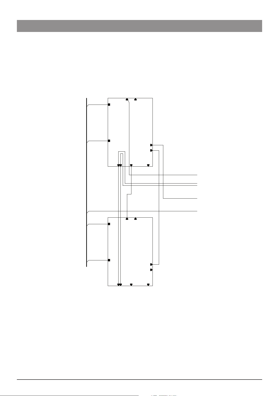
Cabling Diagrams
2 Horizontal Module
Spare Parts Replacement Procedures
Beacon
BEACON LONG
1000EL 00 784
EARTH
1000SP 00452
100 0E L 00712
ETHERNET 2 ( J7)
ETHE RNET IN(J3)
2-H Tile board
EARTH
1000SP 00452
POWER IN (J6)
POWER OUT (J1)
J13- Beacon
1000EL 00675
1000EL 00690
1000EL 00689
1000SP 00452
EXTRUSION CENTRE RAIL
J4-NEUTRAL
J5 -LIVE
ETHERNETOUT (J2)
Alaris® Gateway Workstation 36/67 1000SM00015 Issue 4
Page 37

Spare Parts Replacement Procedures
Cabling Diagrams (continued)
2 Vertical Module
Beacon (J13)
1000EL 00689
POWER IN (J6)
POWER OUT (J1)
2-V Til eBoard
ETHERNET OUT(J2)
J4 - NEUTRAL
J5 - LIVE
EARTH
1000SP 004 52
EARTH
1000SP00452
EXTRUSION CENTRE RAIL
100 0EL 00 708
ETHERNET 2 (J7)
ETHERNET IN(J3)
1000EL 00675
1000SP 00452
1000EL 00690
SEENOTE
NOTES:
In systems larger than a 3XX, connect cable 1000EL00674 to J7ofthe2VModule
Alaris® Gateway Workstation 37/67 1000SM00015 Issue 4
Page 38

Spare Parts Replacement Procedures
Cabling Diagrams (continued)
3 Horizontal Module
Beacon
BEACON L ONG
1000E L0 0784
Nurse call (J18)
ETHERNET IN (J3)
EARTH
1000SP 00452
EARTH
1000SP 00452
1000EL00716
POWER IN (J1)
1000SP 00452
1000EL 00675
1000EL 00689
3-HTile board
EXTRUSION CENTRE RAIL
EARTH
1000SP 00452
1000EL 00691
POWER OUT (J6)
J5 -LIVE
ETHERNE T OUT(J 2)
J4 -NEUTRAL
Beacon (J13)
Alaris® Gateway Workstation 38/67 1000SM00015 Issue 4
Page 39
Spare Parts Replacement Procedures
Cabling Diagrams (continued)
4 Horizontal Module
1000SP 00452
EARTH
1000EL 00712
ETHERN ET 2 ( J7)
ETHERNET IN (J3)
EXTRUSIONCENTRE RAIL
EARTH
1000SP 00452
J5 - LIVE
J4 - NEUTRAL
1000EL 00691
EARTH
1000SP 00452
EARTH
1000SP 00452
1000EL 00675
ETHERNET IN (J3)
2-HTileboard
ETHER NET OUT (J2)
ETHERNE T 2 (J 7)
2-H Tileboard
POWER IN (J6)
POWER OUT (J1)
J13- Beacon
1000EL 00785
1000EL 00690
1000EL 00689
1000SP 00452
1000E L 00 712
1000EL 00 688
POWER IN (J6)
POWER OUT (J1)
J4 - NEUTRAL
ETHERNE T OUT(J 2)
J5 - LIVE
J13-Beac on
BEACON NOT FITTED TO 4H MODULE
Alaris® Gateway Workstation 39/67 1000SM00015 Issue 4
Page 40

Spare Parts Replacement Procedures
Cabling Diagrams (continued)
Base Unit (option 1)
KEYPAD
1000L B00617
1000EL 00688
J13-Beacon
J1-POWER OUT
J2-E THERNET OUT
J4-NEUTRAL
J5-LIVE
EARTH
1000S P 00 452
J6- POWER IN
3-V Tile board
EARTH
1000SP00452
1000EL006 74
J18-Nurse call
J2-Keypad[9..0]
J3-E THERNET IN
J5-TILE POWER
CHASS IS
J1-1 5V IN
LV P S BOARD
EARTH
1000EL 00636
1000S P 00 452
1000EL00675
1000E L0079 9
1000EL 006761000E L00677
J3-S ERVICES
J4-S E R VICES POW ER OUT
J6-B ATT E R Y
1000E L006 28
EXTRUSION CENTRE RAIL
1000EL 00682
1000E L 0068 3
CHASSIS 1000EL00687
100 0EL 0068 4
BATTERY
BATTERY PACK
100 0SP 00605
1000EL 00686
J3-15V OUT
PSU
MAINS E
CHASSIS
MAINS L
MAINSN
1000EL 00685
NEUTRAL
LIVE
IE C MAINSIE C MAINS
IEC MAINSIEC MAINS
MAINS OUT
MAINS IN
1000EL 00765
PE S TUDPE S TUD
EARTH
1000EL008 02
CHASSIS
J6-Nurse call
J3-Tile E thernet
J1-Servic es Ethernet
UPPER POD
J5-NURSECALL OUT
J2- EXT ETHER
J4- AUX ETH ER
ETHERNET ISOLAT ION BOARD
1000EL00 655
1000E L0 0679
LOWER POD
1000SP00636
BASE UNIT WITH OPTION 01
Alaris® Gateway Workstation 40/67 1000SM00015 Issue 4
Page 41

Spare Parts Replacement Procedures
Cabling Diagrams (continued)
Base Unit (option 2)
Beacon
BEACON
1000EL 0069 3
KEYPAD
1000L B00617
1000EL 00688
J13-Beacon
J1-POWER OUT
J2-E THERNET OUT
J4-NEUTRAL
J5-LIVE
EARTH
1000S P 00452
Connect 1000EL00674 to J7 on 2V moduleswhen fitted
J6-POWER IN
3-V Tile board
EARTH
1000SP 00452
100 0EL006 74
J18-Nurse call
J2-Keypa d[9..0]
J3-E THERNET IN
J5- TI LE POWER
CHASSIS
J1-15VIN
1000EL00687
LV P S BOARD
EARTH
1000E L 00636
1000SP 00 452
100 0E L 00675
1000EL 0079 9
J16- CHAS S IS
J9-ETHE R NET S
AA1100
1000E L 00 676
J4- QU AD R S 232
J13-L CD DISPLAY
GSBUNIT
3-ET HERNET
J
J3-S ERVICES
J4-S E R VICES POWER O UT
J6-BATTERY
1000EL00628
EXTRUSION CENTRE RAIL
1000EL 006 83
100 0EL 00682
VICES
J1- SER
J2-POWER IN
J11 -SP E AKER
J15-BARCODE
J14-ISO RS232
1000EL006 38
CHASSIS
1000EL00684
BATTERY
SMART BATTE R Y
1000S P 00605
1000EL006 86
J3-15V OUT
PSU
MAINS N
CHASSIS
MAINS L
MAINS E
1000EL 00685
NEUT R AL
LIV E
S
IE C MAINSIE C MAIN
IEC MAINSIEC M AINS
MAINS OUT
MAINSIN
1000E L0 07 65
PE STUDPE STUD
EARTH
1000EL 00680
BARCODE
1000E L0 0802
CHASSIS
J6-Nurse ca ll
J3-TileEthe rnet
J1-S ervices Ethernet
UPPER POD
J5- NUR S EC ALLOU T
J2- EXT ETHER
J4- AUXETHER
ETHERNET ISOLATIONBOARD
1000EL0067 7
1000EL00681
1000E L 00 679
SPEAKER ASSY 1000S P 006 52
100 0EL006 55
LOWER POD
CONFIGURATION SHOWN IS 3X0
BASE UNIT 02INCLUDING SERVICES BOARD
Alaris® Gateway Workstation 41/67 1000SM00015 Issue 4
Page 42

Spare Parts Replacement Procedures
Cabling Diagrams (continued)
Base Unit (option 3)
Beacon
BEACON
100 0EL006 93
KEYPAD
100 0L B00617
1000EL 00688
J13-Beacon
J1-POWER OUT
J2-E THERNET OUT
J4-NEUTRAL
J5-LIVE
EARTH
100 0SP00452
Connect 1000EL00674 to J7 on 2V modules when fitted
J6- POWER IN
3-V Tileboard
EARTH
100 0SP00452
1000EL006 74
J18-Nurse call
J2- Keypad[9..0]
J3-E THERNET IN
J5- TILE POWER
CHASS IS
J1-1 5VIN
LVPS BOARD
J3- SERVICES
J4- SERVICES POWER OUT
EARTH
100 0EL00636
100 0SP00452
100 0EL00675
1000E L00799
WiFiPCMCIA
1000EL 00676
100 0EL00824
AA1100
J4-Q U AD R S232
J13-L CD DISPLAY
GSBUNIT 2
J1-S ERVICES
J16- CH ASS IS
J9-E THERNET S
J3- ETHERNET
J11-S P E AK E R
J15-B AR C ODE
J6- BATTERY
1000EL 0 062 8
EXTRUSION CENTRE RAIL
1000EL 00682
1000EL 0068 3
J2-POWER IN
J14-ISO R S232
100 0EL 00638
CHASSIS 1000EL006 87
100 0EL 006 84
BATTERY
SMAR T BATT E R Y
1000SP00 60 5
100 0E L00686
J3- 15V OUT
PSU
MAINS E
MAINS L
CHASSIS
MAINSN
1000EL 00685
NEUT R AL
LIVE
IE C MAINSIE C MA IN S
IE C MAINSIEC MAINS
MAINS OUT
MAINS IN
100 0EL007 65
PE S TUDPE S TUD
EARTH
BARCODE READER
1000EL00769
1000EL00 802
CHAS SIS
J6-N urse call
J3-Tile E thernet
100 0E L 00680
UPPER POD
ETHERNET ISOLATIONBOARD
BARCODE
J1-Servic es Ethernet
J5-NUR S E CAL L OUT
J2- EXT ETHER
J4- AUX ETH ER
1000EL 0067 7
100 0EL00681
1000EL 00679
SPEAKER ASSY 1000SP0065 2
1000EL00 655
LOWER POD
AND OPTIONAL BARCODE READER
CONFIGURATION SHOWN IS 3X0 WITH BEACON
AND WIRELESS LAN.
BASE UNIT03INCLUDING SERVICES BOARD
Alaris® Gateway Workstation 42/67 1000SM00015 Issue 4
Page 43

Spare Parts Replacement Procedures
Cabling Diagrams (continued)
Configurations - 3X, 5X
J3
J7
SEE NOTE 2
J7
J3
4H MODULE
1000SP00635
J2
J13
BEACON LONG
1000EL00784
J3
3H MODULE
1000SP00634
J13
J2
1000EL 00690
1000EL 00674
1000EL 00785
1000SP 00452
1000EL 00689
BASE MODULE
J1 L/NEJ2
100 0EL007 85
1000EL 00690
1000EL 00674
1000EL 00675
1000SP 00452
1000EL 00689
BASE MODULE
J1 L/NEJ2
OR
1000SP00636+1000SP00649OR1000SP00650
1000SP00651
OR
1000SP00636+1000SP00649OR1000SP00650
1000SP00651
3X4
4H MODULE
J2
1000SP00635
BEACON LONG
1000EL00784
3H MODULE
1000SP00634
J2J2
J13
J3
J13
1000EL 00690
1000SP00632
2V MODULE
J7
2V MODULE
SEE NOTE2
J7
1000EL 00785
1000SP 00452
1000EL 00689
J1 L/NE J2
1000EL 00691
1000EL 00675
1000SP 00452
1000SP00632
1000EL 00689
J1 L/NEJ2
1000EL 00689
1000EL 00674
1000EL 00675
J2
1000SP 00452
1000EL 00690
J1 E L/N
1000EL 00689
1000EL 00674
1000EL 00675
J2
1000SP 00452
1000EL 00690
OR
BASE MODULE
1000SP00636+1000SP00649
BASE MODULE
1000SP00636OR1000SP00650OR1000SP00651
5X4
1000SP00650OR1000SP00651
1000E L 00675
BEACONLONG
3X2 3X3
3X0
1000EL00784
J7
2HMODULE
1000SP00633
J13 J3
BEACON
SEE NOTE 2
1000EL 00690
1000EL 00675
1000SP 00452
1000SP00632
1000EL 00689
1000EL00693
2V MODULE
J1L/NEJ2
J7 J7
1000SP00632
2V MODULE
J13
1000EL 00689
1000EL 00674
1000EL 00675
J2
1000SP 00452
1000EL 00690
BASE MODULE
1000SP00636OR1000SP00650OR1000SP00651
SEE NOTE 2
1000EL 00689
1000EL 00674
1000EL 00675
J2
1000SP 00452
1000EL 00690
BASE MODULE
1000SP00636OR1000SP00650OR1000SP00651
J1 EL/N J1EL/N J1 E L/N
5X0 5X2 5X3
BEACON LONG
1000EL00784
SEE NOTE 4 SEE NOTE 4 SEE NOTE 4
J7
J3
2HMODULE
1000SP00633
J2
J13
1000EL 00675
BEACON
1000EL 00675
1000SP 00452
1000EL 00689
SEENOTE1
1000EL00693
1000EL 00690
1000EL 00674
+
1000SP00636
1000SP00649OR1000SP00650
OR
OR
1000SP00650
1000SP00651
OR
1000SP00651
1000EL 00674
J2
J1 L/NE
J2
BASE MODULE
J13
BASE MODULE
1000SP00636
3) NO BEACON FITTED TO XX4HMODULES
4) USE ETHERNET COUPLER 0000EL00942
2) IN 5XX SYSTEMS, CABLE 1000EL00674CONNECTED TO J7 OF2V MODULE
NOTES:
1) IN 3X0 SYSTEMS, CABLE 1000EL00674 CONNECTED TO J2 OF BASE MODULE
Alaris® Gateway Workstation 43/67 1000SM00015 Issue 4
Page 44

Spare Parts Replacement Procedures
Cabling Diagrams (continued)
Configurations - 7X
J7
J3
EENOTE 1
S
4H MODULE
J2
1000SP00635
BEACON LONG
3H MODULE
J2
1000EL00784
1000SP00634
1000EL 00690
1000EL 00785
1000SP 00452
1000EL 00689
J1 L/NEJ2
J13
J7
1000EL 00691
J3
J13
1000EL 00675
1000SP 00452
1000SP00632
1000EL 00689
J1 L/NEJ2
J7
1000SP00632
2V MODULE
2V MODULE
1000EL 00689
1000EL 00675
1000SP 00452
1000EL 00690
J1L/NE J2
1000EL 00689
1000EL 00675
1000SP 00452
1000SP00632
1000EL 00690
J1 L/NEJ2
J7
1000SP00632
2V MODULE
SEE NOTE 1
J7
2V MODULE
1000EL 00689
1000EL 00674
1000EL 00675
J2
1000SP 00452
1000EL 00690
BASEMODULE
1000SP00636+1000SP00649OR1000SP00650OR1000SP00651
J1 E L/N
1000EL 00689
1000EL 00674
1000EL 00675
J2
1000SP 00452
1000EL 00690
BASEMODULE
1000SP00636OR1000SP00650OR1000SP00651
7X4
BEACON LONG
1000EL00784
J7
2H MODULE
1000SP00633
J13 J3
J2
1000EL 00690
1000EL 00675
1000SP 00452
1000EL 00689
BEACON
1000EL00693
2V MODULE
1000SP00632
J1 L/NEJ2
J7 J7 J7
1000SP00632
2V MODULE
J13
1000EL 00689
1000EL 00675
1000SP 00452
1000SP00632
1000EL 00690
J1 L/NE J2
1000EL 00689
1000EL 00675
1000SP 00452
1000SP00632
1000EL 00690
J1 L/NE J2
2V MODULE
2V MODULE
SEE NOTE 1
1000EL 00689
1000EL 00674
1000EL 00675
J2
1000SP 00452
1000EL 00690
BASE MODULE
1000SP00636OR1000SP00650OR1000SP00651
SEE NOTE 1
1000EL 00689
J7 J7
1000EL 00674
1000EL 00675
J2
1000SP 00452
1000EL 00690
J1 E L/N J1 E L/N J1 E L/N
BASE MODULE
1000SP00636OR1000SP00650
OR
7X0 7X2 7X3
1000SP00651
2) NO BEACONFITTEDTOXX4H MODULES
NOTES:
1) IN 7XX SYSTEMS, CABLE1000EL00674 CONNECTED TOJ7OF 2V MODULE
Alaris® Gateway Workstation 44/67 1000SM00015 Issue 4
Page 45

Spare Parts Replacement Procedures
Cabling Diagrams (continued)
Configuration - 9-2
2H MODULE
J2
1000SP00633
J13 J3
1000SP00452
1000EL00689
1000EL00675
L
J1
J1 L/NE J2
J1 L/NE J2
1000SP00632
2V MODULE
J7
1000SP00452
1000EL00690
1000EL00675
1000SP00632
2V MODULE
J7
1000SP00452
1000EL00690
1000EL00675
/NEJ2
J7
1000EL00690
1000EL00689
1000EL00689
BEACON LONG
1000EL00784
Configuration - 2-3-5
J1 L/NEJ2J13
1000SP00632
2V MODULE
1000EL00690
1000SP00452
BASE MODULE
1000SP01282
1000EL00962
BEACON
1000EL00693
J7
1000EL00675
1000EL00674
J2J1 E L/N
1000EL00961
0000EL00951
1000EL00959
1000EL00689
0000EL00953
This module may be upgraded with
OPTION 2 KIT - 1000SP00650
1000SP00632
2V MODULE
J7
1000SP00452
1000EL00690
1000EL00675
1000EL00674
J2
J1 E L/N
BASE MODULE
1000SP00636
OR
1000SP00650
OR
1000SP00651
1000EL00689
SEE NOTE 1
9x2
NOTES:
1) CABLE1000EL00674 CONNECTED TOJ7OF 2V MODULE
L/N
J2
J6
0000EL00952
E
3H MODULE
1000SP01281
E
J1
1000EL00689
1000SP00452
J1
J2
1000SP01290
2V MODULE
J7
J3
J3
1000EL00691
L/NE
Alaris® Gateway Workstation 45/67 1000SM00015 Issue 4
Page 46

Labels
Spare Parts Replacement Procedures
(A5)
(A3)
(A2)
(A5)
(A3)
(A4)
(A1)
(A3) (A3)
(A2)
(A4)
(A5)
(B)
(B)
(A5)
(A1)
Alaris®
Gateway Workstation
Spare Parts
Item Description Part Number
A LABEL SET ALARIS GATEWAY 1000LB01415
B LABEL AGW LOGO 1000LB01416
Alaris® Gateway Workstation 46/67 1000SM00015 Issue 4
Page 47

Trolley Mounting Kit
Fitting Procedure
Remove the plastic coating from the inner and outer surfaces of the Ring Clamp (A).1.
Slide one ring clamp over each trolley pole.2.
Align the Cross Bar (B) fixing holes with those in each of the Ring Clamps.3.
Insert the Fixing Screw (C) through the assembly positioning washers (D) and (E) as shown.4.
Position the support bar and tighten the Thin Nut (G), Dome Nut (F) and screw to 3Nm.5.
(C) Screw
Spare Parts Replacement Procedures
(E) Bellville
Spring (x4)
(A) Ring Clamp
(F) Dome Nut
(E) Washer (x4)
(B) Cross Bar
(G) Nut (x2)
Spare Parts
Item Description Part Number
A RING CLAMP 1000SP01187
B CROSS BAR "
C SCREW SKT TAP M6 X 25 DIN 912 "
D WASHER PLAIN M6 DIN 125 "
E BELLVILLE WASHER, LEE SPRINGS 250-025-500 "
F NUT DOME M6 DIN 1587 "
G THIN NUT "
Alaris® Gateway Workstation 47/67 1000SM00015 Issue 4
Page 48
Spare Parts Replacement Procedures
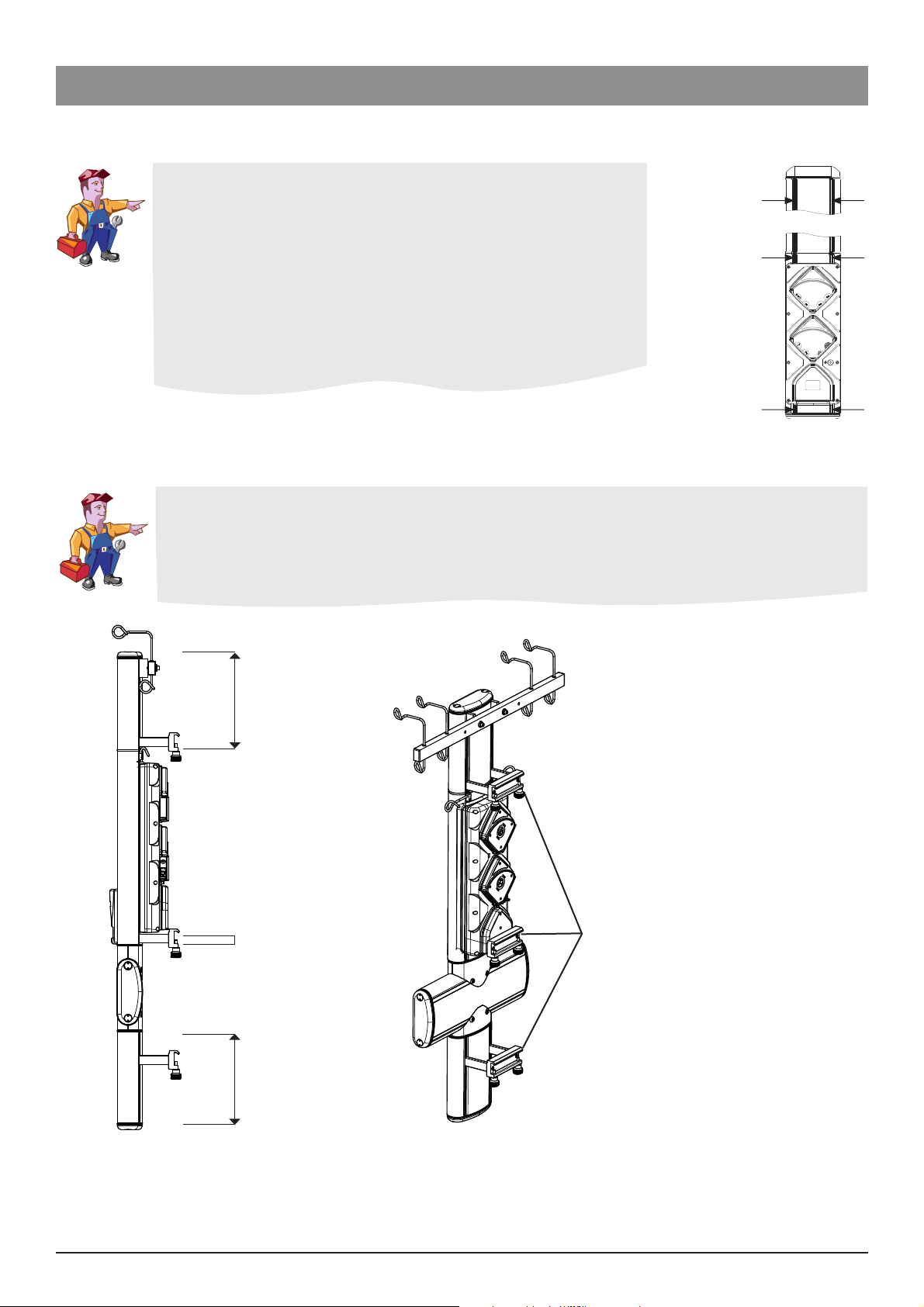
Trolley Mounting Kit (continued)
Fitting the Workstation to a trolley
When fixing the Workstation to the trolley, the mounting kits should be 1.
positioned and tightened so that the mount clamps align with the 10 x
25mm bars on the trolley.
The Workstation should then be mounted so both top and bottom mount 2.
clamps fit over the 10 x 25mm bars on the trolley.
The knobs should be tightened in order to fully restrain the Workstation 3.
into position.
Note: The mounting locations for the Workstation must be positioned as
shown dependant on the configuration.
5X, 7X and 9X
All Con gurations
All Con gurations
Mounting Locations
Fitting the Workstation configuration 2x3x5 to a trolley
Con gurations where volumetric pumps are not located at the top require three separate rail clamps
Points 1,2 and 3 must always be located within the area shown below.
1
2 (Fixed location)
3 Rail Clamps
3
Alaris® Gateway Workstation 48/67 1000SM00015 Issue 4
Page 49

Spare Parts Replacement Procedures
Bar Mounting Kit
Fitting Procedure
Remove Sealing Cord from the channel. Using an Allen key, remove the fasteners from the pre-fitted Square Nuts (A) in the 1.
extrusion channel. Using a screwdriver or similar pointed tool, slide the loosened Square Nuts along the channel to the required
position.
Insert the two Screws (C) through the Clamp (B) and Spacers (D).2.
Tighten the Screws ensuring that the mounting kit remains level.3.
Insert the Mounting Knobs (E) into the Clamp.4.
Repeat the process for the second kit.5.
Cut a length of Sealing Cord to fill the channel between the mounting kit and the end caps.6.
Carefully press the cord into place.7.
Repeat the operation for the remaining sections of the channel.8.
NOTE: C.H.A.P. only recommend mounting kits to be fitted to the vertical extrusion.
(C) Screw (x2)
(B) Clamp
(D) Spacer
(E) Mounting
Knob (x2)
(A) Square Nut (x2)
See Trolley Mounting Kit section for mounting location instructions.
Spare Parts
Item Description Part Number
A NUT SQUARE M6 DS 0000ME00432
B GATEWAY MOUNTING KIT EXTENDED TYPE 1 1000SP00655
C SCREW SKT HEAD CAP M6x100 A2 ISO4762 "
D SPACER, MOUNTING AGW "
E KNOB MOUNTING "
Alaris® Gateway Workstation 49/67 1000SM00015 Issue 4
Page 50

Spare Parts Replacement Procedures
Pole Mounting Kit
Fitting Procedure
Remove Sealing Cord from the channel. Using an Allen key, remove the fasteners from the pre-fitted Square Nuts (A) in the 1.
extrusion channel. Using a screwdriver or similar pointed tool, slide the loosened Square Nuts along the channel to the required
position.
Insert the two Screws (C) through the Clamp (B) and Spacers (D).2.
Tighten the Screws ensuring that the mounting kit remains level.3.
Insert the Mounting Knobs (E) into the Clamp.4.
Repeat the process for the second kit.5.
Cut a length of Sealing Cord to fill the channel between the mounting kit and the end caps.6.
Carefully press the cord into place.7.
Repeat the operation for the remaining sections of the channel.8.
(C) Screw (x2)
(B) Clamp
(D) Spacer
(A) Square Nut (x2)
See Trolley Mounting Kit section for mounting location instructions.
Spare Parts
Item Description Part Number
A NUT SQUARE M6 DS 0000ME00432
B POLE CLAMP MOUNTING ASSEMBLY NARROW 1000SP00169
C SCREW SKT HEAD CAP M6x100 A2 ISO4762 *
D SPACER, MOUNTING LONG *
* Not available separately only as part of the Gateway Mounting Kit Extended Type 1 (1000SP00655). When replacing the bar mounting
kit with the pole clamp mounting kit the spacers and screws already fitted should be used where possible.
Alaris® Gateway Workstation 50/67 1000SM00015 Issue 4
Page 51

Appendix A
Electromagnetic Compatibility
Page 52

Electromagnetic Compatibility
Electromagnetic Compatibility
Warning:
• The use of any accessory, transducer, or cable with the Workstation other than those specified may result in increased emissions or
decreased immunity of the Workstation.
• The Workstation should not be used adjacent to or stacked with other equipment, however if adjacent or stacked use is necessary,
the Workstation should be observed to verify normal operation in the configuration in which it will be used.
Caution:
• The Workstation is a CISPR 11 Group 1 Class A Medical Equipment System and intended for use by healthcare professionals only.
• Medical Electrical Equipment needs special precautions regarding EMC and needs to be installed, put into service and used
according to the EMC information provided in the accompanying documents.
• Portable and Mobile RF communications can affect Medical Electrical Equipment.
• Operating the Workstation near equipment which radiates high energy radio frequencies (electro surgical or cauterizing equipment,
portable radios, cellular telephones, etc.) may cause false alarm conditions. If this happens, reposition the Workstation away from
the source of interference or turn off the Workstation and manually regulate the flow.
Guidance and Manufacturer’s Declaration – Electromagnetic Emissions
The Workstation is intended for use in the electromagnetic environment specified below.
The customer or the user of the Workstation should assure that it is used in such an environment.
Emissions Test Compliance Electromagnetic Environment – Guidance
CISPR 11
RF Emissions
CISPR 11
RF Emissions
EN 61000-3-2
Harmonic Emissions
EN 61000-3-3
Voltage Fluctuations,
Flicker Emissions
Group 1
Class A system when
used in conjunction
with pumps
Class B in stand alone
operation
Class A
Complies
The Workstation uses RF energy only for its internal function in the normal
product offering. Therefore, its RF emissions are very low and are not likely to
cause any interface in nearby electronic equipment.
The Workstation is suitable for use in all establishments, other than domestic,
and those directly connected to the public low-voltage power supply network
that supplies buildings used for domestic purposes.
Alaris® Gateway Workstation 52/67 1000SM00015 Issue 4
Page 53

Electromagnetic Compatibility
Guidance and Manufacturer’s Declaration - Electromagnetic Immunity
The Workstation is intended for use in the electromagnetic environment specified below.
The customer or the user of Workstation should assure that it is used in such an environment.
Immunity Test
EN 61000-4-2 Electro-Static
Discharge (ESD)
EN 61000-4-4
Electrical Fast Transient, Burst
(EFT) (Note 3)
EN 61000-4-5
Power Line Surge
(Note 3)
EN 61000-4-8 Power
Frequency Magnetic Field
(50/60 Hz)
EN 61000-4-11
Voltage Dips, Short
Interruptions, and Voltage
Variations
(Note 3)
EN 60601-1-2
Test Level
±6 kV contact
±8 kV air
Compliance Level Electromagnetic Environment – Guidance
±8 kV contact (Note
2)
±15 kV air (Note 2)
±2 kV for power
supply lines
±1 kV for input/
±2 kV for power
supply lines
N/A (Note 4)
output lines
±1 kV Line(s) to
Line(s)
±2 kV Line(s) to
Earth
±1 kV Line(s) to
Line(s)
±2 kV Line(s) to Earth
3 A/m 400 A/m 50 Hz
(Note 2)
<5 % UT (Note 1)
(>95 % dip in UT)
for 0.5 cycle
40 % UT
(60 % dip in UT)
for 5 cycles
70 % UT
(30 % dip in UT)
for 25 cycles
<5 % UT
(>95 % dip in UT)
for 0.5 cycle
40 % UT
(60 % dip in UT)
for 5 cycles
70 % UT
(30 % dip in UT)
for 25 cycles
Floors should be wood, concrete, or ceramic tile.
If floors are covered with synthetic material, the
relative humidity should be at least 30 %.
Mains power quality should be that of a typical
commercial or hospital environment.
Mains power quality should be that of a typical
commercial or hospital environment.
Power frequency magnetic fields should be at
levels characteristic of a typical location in a typical
commercial or hospital environment.
Mains power quality should be that of a typical
commercial or hospital environment.
If the user of the Workstation requires continued
operation during power mains interruptions, it is
recommended that the Workstation be powered
from an uninterruptible power supply or a battery.
The Workstation does employ an internal short
duration battery.
<5 % UT
(>95 % dip in UT)
for 5 sec
Note 1—UT is the AC mains voltage prior to application of the test level.
Note 2—Compliance levels raised by EN 60601-2-24.
Note 3—Performed at the Minimum and Maximum Rated Input Voltage.
Note 4—Cardinal Health recommends using signal cables of less than 3 meters in length and this requirement is applicable only if signal cables are 3
meters or more in length. (EN 60601-1-2:2002, Clause 36.202.4)
Alaris® Gateway Workstation 53/67 1000SM00015 Issue 4
<5 % UT
(>95 % dip in UT)
for 5 sec
Page 54

Electromagnetic Compatibility
Guidance and Manufacturer’s Declaration—Electromagnetic Immunity
LIFE SUPPORT Equipment
The Workstation is intended for use in the electromagnetic environment specified below.
The customer or the user of the Workstation should ensure that it is used in such an environment.
Immunity Test
EN 61000-4-6
Conducted RF
EN 61000-4-3
Radiated RF
EN 60601-1-2
Test Level
3 V rms
150 kHz to 80
MHz
3 V/m
80 MHz to 2.5 GHz
Compliance
Level
10 V rms
(Note 3)
10 V/m
(Note 3)
Electromagnetic Environment – Guidance
Portable and mobile RF communications equipment should be used
no closer to any part of the Workstation, including cables, than the
recommended separation distance calculated from the equation applicable
to the frequency of the transmitter.
Recommended Separation Distance
3.5
d = [-----] √P
V
1
12
d = [-----] √P 80 MHz to 800 MHz
V
2
12
d = [-----] √P 80 MHz to 2.5 GHz
E
1
23
d = [-----] √P 800 MHz to 2.5 GHz
E
1
where P is the maximum output power rating of the transmitter in watts
(W) according to the transmitter manufacturer and d is the recommended
separation distance in meters (m).
a
Field strengths from fixed RF transmitters, as determined by an
electromagnetic site survey, b should be less than the compliance level in
each frequency range.
c
Interference may occur in the vicinity of equipment marked with the
following symbol:
Note 1—At 80 MHz and 800 MHz, the higher frequency range applies.
Note 2—These guidelines may not apply in all situations. Electromagnetic propagation is affected by absorption and reflection from structures, objects,
and people.
Note 3—Compliance levels raised by EN 60601-2-24.
a The compliance levels in the ISM frequency bands between 150 kHz and 80 MHz and in the frequency range 80 MHz to 2.5 GHz are intended to
decrease the likelihood that mobile/portable communications equipment could cause interference if it is inadvertently brought into patient areas. For
this reason, an additional factor of 10/3 is used in calculating the recommended separation distance for transmitters in these frequency ranges.
b Field strengths from fixed transmitters, such as base stations for radio (cellular/cordless) telephones and land mobile radios, amateur radio, AM and
FM radio broadcast, and TV broadcast cannot be predicted theoretically with accuracy. To assess the electromagnetic environment due to fixed RF
transmitters, an electromagnetic site survey should be considered. If the measured field strength in the location in which the Workstation is used
exceeds the applicable RF compliance level above, the Workstation should be observed to verify normal operation. If abnormal performance is
observed, additional measures may be necessary, such as re-orienting or relocating the Workstation.
c Over the frequency range 150 kHz to 80 MHz, field strengths should be less than 10 V/m.
Alaris® Gateway Workstation 54/67 1000SM00015 Issue 4
Page 55

Electromagnetic Compatibility
Recommended Separation Distances for LIFE SUPPORT Equipment between
portable and mobile RF communications equipment and the Alaris® Gateway Workstation
The Workstation is intended for use in an electromagnetic environment in which
radiated RF disturbances are controlled.
The user of the Workstation can help prevent electromagnetic interference by maintaining a minimum distance between portable and
mobile RF communications equipment (transmitters) and the Workstation as recommended below, according to the maximum output
power of the communications equipment.
Separation Distance According to Frequency of Transmitter
Rated Maximum Output
Power of Transmitter
W
150 kHz to 80 MHz
Outside ISM bands 3.5
d = [------] √P
V1
150 kHz to 80 MHz
In ISM bands
12
d = [------] √P
V2
m
80 MHz to 800 MHz
12
d = [ ------] √P
E1
800 MHz to 2.5 GHz
23
d = [------] √P
E1
0.01
0.1
1
10
100
For transmitters rated at a maximum output power not listed above, the recommended separation distance d in meters (m) can be determined using the
equation applicable to the frequency of the transmitter, where P is the maximum output power rating of the transmitter in watts (W) according to the
transmitter manufacturer.
Note 1—At 80 MHz and 800 MHz, the separation distance for the higher frequency range apply.
Note 2—The ISM (Industrial, Scientific, and Medical) bands between 150 kHz and 80 MHz are 6.765 MHz to 6.795 MHz; 13.553 MHz to 13.567 MHz; 26.957
MHz to 27.283 MHz; and 40.66 MHz to 40.70 MHz.
Note 3—An additional factor of 10/3 is used in calculating the recommended separation distance for transmitters in the ISM frequency bands between
150 kHz and 80 MHz and in the frequency range 80 MHz to 2.5 GHz to decrease the likelihood that mobile/portable communications equipment could
cause interference if it is inadvertently brought into patient areas.
Note 4—These guidelines may not apply in all situations. Electromagnetic propagation is affected by absorption and reflection from structures, objects,
and people.
0.03 0.12 0.12 0.23
0.11 0.38 0.38 0.73
0.35 1.20 1.20 2.30
1.11 3.80 3.80 7.28
3.50 12.00 12.00 23.00
Alaris® Gateway Workstation 55/67 1000SM00015 Issue 4
Page 56

Spare Parts Listing
In this appendix
Module Assemblies 57
Cables 58
Appendix B
Rear Cover 58
Saddle Kit 58
Pod Kit 58
Front Cover Kit 59
LVPS Board 59
PSU Kit 59
Battery Pack 59
Tile Assemblies 59
Ethernet Isolation Board 59
Labels 59
Hardware Kit 60
Miscellaneous Hardware 60
Trolley Mounting Kit 60
Bar Mounting Kit 61
Pole Mounting Kit 61
End Covers/Tile Spacers 61
Beacon Horizontal 61
Beacon Vertical 61
Page 57

Module Assemblies
Module Description Part Number
Spare Parts Listing
Option 2 Upgrade Kit 1000SP00650
Option 3 Upgrade Kit (for option 2 only)
Wireless LAN Card
Barcode Reader Spares Kit 1000SP00651
2 High Vertical Module Assembly 1000SP00632
2 Wide Horizontal Module Assembly 1000SP00633
3 Wide Horizontal Module Assembly 1000SP00634
1000EL00824
4 Wide Horizontal Module Assembly 1000SP00635
Alaris® Gateway Workstation 57/67 1000SM00015 Issue 4
Page 58

Cables
Spare Parts Listing
Part Number Description Qty
1000EL00802 Assembly Cable Earth Ethernet Isolation 1 Ea
1000EL00799 Assembly Cable Earth Services Board 1 Ea
1000SP00452 Assy Cable Earth DS/IDS 3 Ea
0000EL00943 Ethernet Cable 2m 1 Ea
1000EL00684 Gateway Cable Assy Battery LVPS 1 Ea
1000EL00677 Gateway Cable Assy Isolated Nurse Call 1 Ea
1000EL00679 Gateway Cable Assy Isolated RS232 1 Ea
1000EL00687 Gateway Cable Assy LVPS Chassis 1 Ea
1000EL00688 Gateway Cable Assy LVPS Tile Power 1 Ea
1000EL00685 Gateway Cable Assy Mains In 1 Ea
1000EL00676 Gateway Cable Assy Nurse Call 1 Ea
1000EL00686 Gateway Cable Assy PSU LVPS Power 1 Ea
1000EL00681 Gateway Cable Assy Services Ethernet 1 Ea
1000EL00682 Gateway Cable Assy Services LVPS 1 Ea
1000EL00683 Gateway Cable Assy Services Power 1 Ea
1000EL00675 Gateway Cable Assy Tile Ethernet In 1 Ea
1000EL00674 Gateway Cable Assy Tile Ethernet Out 1 Ea
Rear Cover
Part Number Description Qty
1000ME00595 Cover Rear Asena Gateway 1 Ea
Saddle Kit
Part Number Description Qty
1000SP01213 AGW SADDLE KIT
Pod Kit
Part Number Description Qty
1000SP01214 AGW POD KIT
Saddle Gasket Asena Gateway 1 Ea
Saddle Rear Cover Asena Gateway 1 Ea
Seal Comms Chimney AGW 1 Ea
Seal Cover Rear Asena Gateway 1 Ea
Seal PSU Chimney AGW 1 Ea
Label Set Alaris Gateway 1 Ea
Pod Comms Asena Gateway 2 Ea
Pod IEC Asena Gateway 1 Ea
Seal Comms Pod Asena Gateway 2 Ea
Seal IEC Pod Asena Gateway 1 Ea
Alaris® Gateway Workstation 58/67 1000SM00015 Issue 4
Page 59

Front Cover Kit
Part Number Description Qty
1000SP01215 AGW FRONT COVER KIT
LVPS Board
Part Number Description Qty
1000EL00628 Assembly PCB LVPS 1 Ea
PSU Kit
Part Number Description Qty
1000SP01216 AGW PSU KIT
Spare Parts Listing
Cover Front AGW 1 Ea
Gateway Keypad Label 1 Ea
Label AGW Logo 1 Ea
Seal Front Cover AGW 1 Ea
Assembly PSU Switch Mode 1 Ea
Thermal Pad PSU 1 Ea
Battery Pack
Part Number Description Qty
1000SP00605 Gateway Assembly Battery Pack 1 Ea
Tile Assemblies
Part Number Description Qty
1000SP00598 Assy Tile Plate 2 High Asena Gateway 1 Ea
1000SP00596 Assy Tile Plate 2 Wide Asena Gateway 1 Ea
1000SP00599 Assy Tile Plate 3 High Asena Gateway 1 Ea
1000SP00597 Assy Tile Plate 3 Wide Asena Gateway 1 Ea
Ethernet Isolation Board
Part Number Description Qty
1000EL00655 Asena Gateway Ethernet Isolation Board 1 Ea
Labels
Part Number Description Qty
1000LB01415 Label Set Alaris Gateway 1 Ea
1000LB01416 Label AGW Logo 1 Ea
Alaris® Gateway Workstation 59/67 1000SM00015 Issue 4
Page 60

Hardware Kit
Part Number Description Qty
1000SP01217 AGW HARDWARE KIT
Spare Parts Listing
Flat Washer Nylon M3 to ISO7089 20 Ea
M4x10 Csk Torx Hd A2 BN13278 20 Ea
Screw Skt Cap M6x20 DIN 6912 20 Ea
M3x16 Pan Hd Torx A2 ISO14583 20 Ea
M3x8 Pan Hd Torx A2 ISO14583 20 Ea
M4x20 Pan Hd Torx A2 BN5653 20 Ea
M4x10 Pan Head BIN 5653 20 Ea
M4x8 Pan Hd Torx A2 BN5653 20 Ea
Star Washer M4 DIN6797 20 Ea
Washer M3 Plain Z+C 20 Ea
Washer M3 Wavey SST 20 Ea
Offset Faston Tab M4 Tinned 10 Ea
Nut M6 Square DS/IDS 20 Ea
Washer M3 Shakeproof External 20 Ea
Washer M6 Plain 20 Ea
Nut M6 Thin 4035 A2 20 Ea
Washer M6 Shakeproof DIN 67898,A2 20 Ea
Nut M6 Plain DIN 934 A2 20 Ea
Washer Earth M6 20 Ea
Screwlock Kit Female RS232 3 Ea
Miscellaneous Hardware
Part Number Description Qty
0000ME00444 Asena GW, Assy, Cover Dust RS232 1 Ea
1000ME00561 Hard Stop Module Spacer Asena Gateway 1 Ea
0000ME00547 PE Stud M6x20 1 Ea
1000ME00562 Shoulder Nut Asena Gateway 1 Ea
1000SP00657 Tube Tidy Kit 1 Ea
1000SP00643 Tie Rod Assy Kit 30 1 Ea
1000SP00644 Tie Rod Assy Kit 50 1 Ea
1000SP00645 Tie Rod Assy Kit 70 1 Ea
1000SP00646 Tie Rod Assy Kit 3H 1 Ea
1000SP00647 Tie Rod Assy Kit 5H 1 Ea
1000SP00648 Tie Rod Assy Kit 7H 1 Ea
Trolley Mounting Kit
Part Number Description Qty
1000SP01187 MOUNTING KIT ASSEMBLY DS TROLLEY
Belville Washer, Lee Springs 250-025-500 4 Ea
Nut Dome M6 DIN 1587 2 Ea
Ring Clamp 2 Ea
Screw Skt Tap M6 X 25 DIN 912 2 Ea
Washer Plain M6 DIN 125 4 Ea
Alaris® Gateway Workstation 60/67 1000SM00015 Issue 4
Page 61

Bar Mounting Kit
Part Number Description Qty
1000SP00655 ASSEMBLY MOUNTING KIT EXTENDED TYPE 1
Pole Mounting Kit
Part Number Description Qty
1000SP00169 ASSEMBLY P/CLAMP DOCKING STATION ASENA
Spare Parts Listing
Knob Mounting 2 Ea
Rail Mounting Clamp DS/IDS 1 Ea
Screw Skt Head Cap M6x100 A2 ISO4762 2 Ea
Spacer, Mounting Long 2 Ea
Plate Mounting P/clamp Dock Stat Asena 1 Ea
Spacer Pole Clamp Docking Station Asena 2 Ea
Nut Square M6 Ds 2 Ea
Screw Skt Cap M6 X 40 St/steel 2 Ea
Pole Clamp 1 Ea
Screw M4x16 Din 7985 Zp+p 4 Ea
Label Logo 1 Ea
Washer M4 Shakeproof 4 Ea
End Covers/Tile Spacers
Part Number Description Qty
1000ME00544 Beacon End Cap Asena Gateway 1 Ea
1000ME00547 Beacon Diffusor 1 Ea
1000ME00545 End Cap Asena Gateway 1 Ea
1000ME00543 End Plate Intermediate Asena Gateway 1 Ea
1000ME00542 Spacer Tile Module Asena Gateway 1 Ea
Beacon Horizontal
Part Number Description Qty
1000EL00784 Cable Assembly Beacon Long 1 Ea
Beacon Vertical
Part Number Description Qty
1000EL00693 Gateway Cable Assembly Beacon 1 Ea
Alaris® Gateway Workstation 61/67 1000SM00015 Issue 4
Page 62

Disposal
Appendix C
Page 63

Disposal
Disposal
Information on Disposal for Users of Waste Electrical & Electronic Equipment
This symbol
U on the product and/or accompanying documents means that used electrical and electronic products
should not be mixed with municipal waste.
If you wish to discard electrical and electronic equipment, please contact your Cardinal Health affiliate office or
distributor for further information.
Disposing of this product correctly will help to save valuable resources and prevent any potential negative effects on
human health and the environment which could otherwise arise from inappropriate waste handling.
Information on Disposal in Countries outside the European Union
This symbol is only valid in the European Union. The product should be disposed of taking environmental factors into
consideration. To ensure no risk or hazard, remove the internal rechargeable battery and the Nickel Metal Hydride battery
from the Services Board and dispose of as outlined by the local country regulations. All other components can be safely
disposed of as per local regulations.
Battery Removal
Removal Procedure
Remove the eight Screws (A) and Washers (B) securing the Rear Cover Assembly to the Power Base Module.1.
Open the Cover Assembly by hinging along one long face. Avoid stressing the connected cables and lay the Cover along side the 2.
assembly.
Disconnect the Battery (C) and remove from saddle slot.3.
(B) Washer (x8)
(A) Screw (x8)
Rear Cover Assembly
(C) Battery Pack
Alaris® Gateway Workstation 63/67 1000SM00015 Issue 4
Page 64

Service Contacts
Appendix D
Page 65

Service Contacts
Service Contacts
For service, contact your local Affiliate Office or Distributor.
AE
Cardinal Health,
PO Box 5527,
Dubai, United Arab
Emirates.
Tel: (971) 4 28 22 842
Fax: (971) 4 28 22 914
www.cardinalhealth.com/
international/distributors/
alaris
AU
Cardinal Health,
3/167 Prospect Highway,
PO Box 355
Seven Hills, NSW 2147,
Australia.
Tel: (61) 2 9838 0255
Fax: (61) 2 9674 4444
www.cardinalhealth.com/au
techservice-au@
cardinal.com
BE
Cardinal Health,
Leuvensesteenweg 248 D,
1800 Vilvoorde,
Belgium.
Tel: (32) 2 267 38 99
Fax: (32) 2 267 99 21
www.cardinalhealth.com/be
gmb-ctsi-tech.belux@
cardinal.com
CA
Cardinal Health,
235 Shields Court,
Markham,
Ontario L3R 8V2,
Canada.
Tel: (1) 905-752-3333
Fax: (1) 905-752-3343
www.cardinalhealth.com/ca
CN
Cardinal Health,
Shanghai Representative
Office, Suite 9B,
Century Ba-Shi Building,
398 Huai Hai Rd(M.),
Shanghai 200020,
China.
Tel: (56) 8621-63844603
Tel: (56) 8621-63844493
Fax: (56) 8621-6384-4025
DE
Cardinal Health,
Pascalstr. 2,
52499 Baesweiler,
Deutschland.
Tel: (49) 2401 604 0
Fax: (49) 2401 604 121
www.cardinalhealth.com/de
DK
Cardinal Health,
Postboks 29,
2820 Gentofte,
Danmark.
Tlf. (45)70 20 30 74
Fax. (45)70 20 30 98
ES
Cardinal Health,
Edificio Veganova,
Avenida de La Vega, nº1,
Bloque 1 - Planta 1,
28108 Alcobendas, Madrid,
España.
Tel: (34) 902 555 660
Fax: (34) 902 555 661
www.cardinalhealth.com/es
servicio.tecnico@cardinal.
com
FR
Cardinal Health,
Immeuble Antares Technoparc,
2, rue Charles-Edouard
Jeanneret.
78300 POISSY,
France.
Tél: (33) 1 30 06 74 60
Fax: (33) 1 39 11 48 34
www.cardinalhealth.com/fr
FR-Assistance-
Technique@cardinal.com
GB
Cardinal Health,
The Crescent, Jays Close,
Basingstoke,
Hampshire, RG22 4BS,
United Kingdom.
Tel: (44) 0800 917 8776
Fax: (44) 1256 330860
www.cardinalhealth.com/alaris
UK-Technical-Support@
cardinal.com
HU
Cardinal Health,
Döbrentei tér 1,
H-1013 Budapest,
Magyarország.
Tel: (36) 14 88 0232
Tel: (36) 14 88 0233
Fax: (36) 12 01 5987
AlarisCE@cardinalhealth.
com
IT
Cardinal Health,
Via Ticino 4,
50019 Sesto Fiorentino,
Firenze, Italia.
Tél: (39) 055 30 33 93 00
Fax: (39) 055 34 00 24
www.cardinalhealth.com/it
assistenza.tecnica@
cardinal.com
NL
Cardinal Health,
De Molen 8-10,
3994 DB Houten,
Nederland.
Tel: (31) 30 228 97 11
Fax: (31) 30 225 86 58
www.cardinalhealth.com/nl
tech.benelux@cardinal.
com
NO
Cardinal Health
Solbråveien 10 A,
1383 ASKER,
Norge.
Tel: (47) 66 98 76 00
Fax: (47) 66 98 76 01
www.cardinalhealth.com/no
technical.supportNO@
cardinal.com
NZ
Cardinal Health,
14B George Bourke Drive,
Mt Wellington 1060,
PO Box 14-518,
Panmure 1741, Auckland,
New Zealand
Tel: 09 270 2420
Freephone: 0508 422734
Fax: 09 270 6285
www.cardinalhealth.com/nz
techservice-nz@cardinal.
com
SE
Cardinal Health,
Hammarbacken 4B,
191 46 Sollentuna,
Sverige.
Tel: (46) 8 544 43 200
Fax: (46) 8 544 43 225
www.cardinalhealth.com/se
technical.supportSE@
cardinal.com
US
Cardinal Health,
10020 Pacific Mesa Blvd.,
San Diego, CA 92121,
USA.
Tel: (1) 858 617 2000
Fax: (1) 858 617 2900
www.cardinalhealth.com/alaris
ZA
Cardinal Health,
Unit 2 Oude Molen Business
Park,
Oude Molen Road, Ndabeni,
Cape Town 7405, South Africa.
Tel: (27) (0) 860 597 572
Tel: (27) 21 510 7562
Fax: (27) 21 5107567
www.cardinalhealth.com/za
SA-Technical-Support@
cardinal.com
Alaris® Gateway Workstation 65/67 1000SM00015 Issue 4
Page 66

Document History
Appendix E
Page 67

Document History
Document History
Issue Date CO No. Author Update Description
1 31/01/06 4974 Martin Burnett Initial release
2 30/06/06 6994 Martin Burnett Rebrand
3 November 2006 7237 Ian Tyler Mounting to trolley instructions added.
4 July 2008 7886 Ian Tyler Revisions to service procedures and update of spare parts.
Alaris® Gateway Workstation 67/67 1000SM00015 Issue 4
 Loading...