

Akira TV CT-21CH9N Schematic

S
S
S
e
e
e
C
C
C
r
v
r
v
r
v
o
o
o
i
i
i
l
l
l
c
c
c
o
o
o
e
e
e
u
u
u
M
M
M
r
r
r
a
T
T
T
a
a
V
V
V
n
n
n
u
u
u
a
a
a
l
l
l

2
M
M
M
o
o
o
d
e
l
G
r
o
u
p
:
C
T
-
d
d
e
e
l
l
G
G
r
r
o
o
u
u
p
p
:
:
C
C
T
T
-
-
2
2
2
CHASSIS: CN-9
MODEL:
1
1
1
C
C
C
H
H
H
9
9
9
CT-21CH9N
Model No: CT-21CH9N
Version 1.0

3
CONTENT
Specifications .......................................................................................4
General description ..............................................................................5
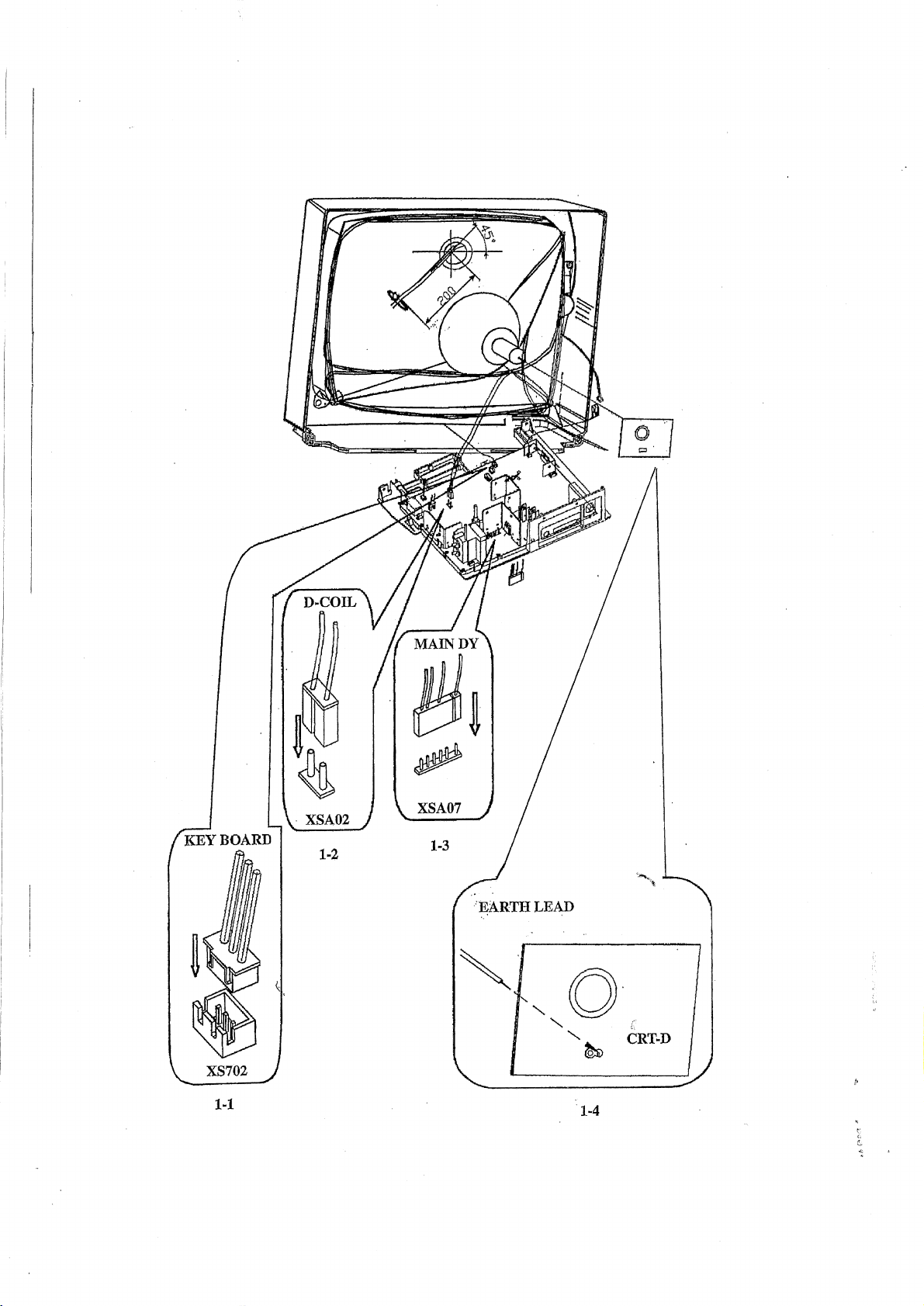
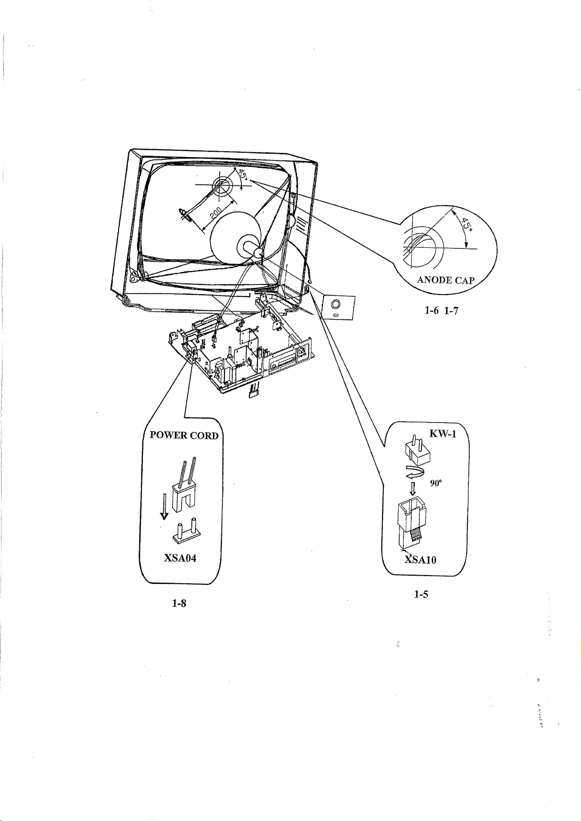
Connector view ....................................................................................8
Safety instructions ..............................................................................11
Circuit adjustments ....................…....................................................12
Set-up adjustment .............................................................................. 13
Service mode general instructions ......................................................15
Service mode adjustment ................................................................... 19
Main repairing flow diagram ..............................................................20
Main ICs description and repair data offering .................................... 26
Spare parts list .……………………………………………………….. 35
Appendix:
Exploded view ………………………………………………………..49
Circuit diagram ……………………………………………………….50
Print lay-out of main board …………………………………………...51
Model No: CT-21CH9N
Version 1.0
SPECIFICATIONS
RF system: Color system: PAIA.43, NTSC3.58, NTSC4.43, PAL-M, PAL-N
Sound system: D/K, I, M, B/G
Video system: PAIA.43, NTSC4.43, NTSC3.58, PAL-M, PAL-N (50/60Hz)
Receiving channel: VHF: Cl~C12 (49.75 ~ 85.25MHz, 168.25 ~ 216.25MHz)
UHF: C 13~C57 (471.25 ~ 863.25MHz)
CATV: Zl~Z7 (111.0 ~ 167.0MHz)
ZS~Z35 (223.0~447.0MHz)
Programs Preset: 236
Antenna. input: 75Ù (imbalance)
Picture tube: Effective screen dimension: 406mmx305mm; Flat-square tube
Audio output: Main channel: 5W+5W (THD=7%)
Power supply: AC 150~260V (50Hz
Weight: ~26kg
Dimensions: 5 66mm(w) x 4551mn(h) x 480mm(d)
Power consumption: ~87W (AC 220V 50Hz)
)
4
Model No: CT-21CH9N
Version 1.0
5
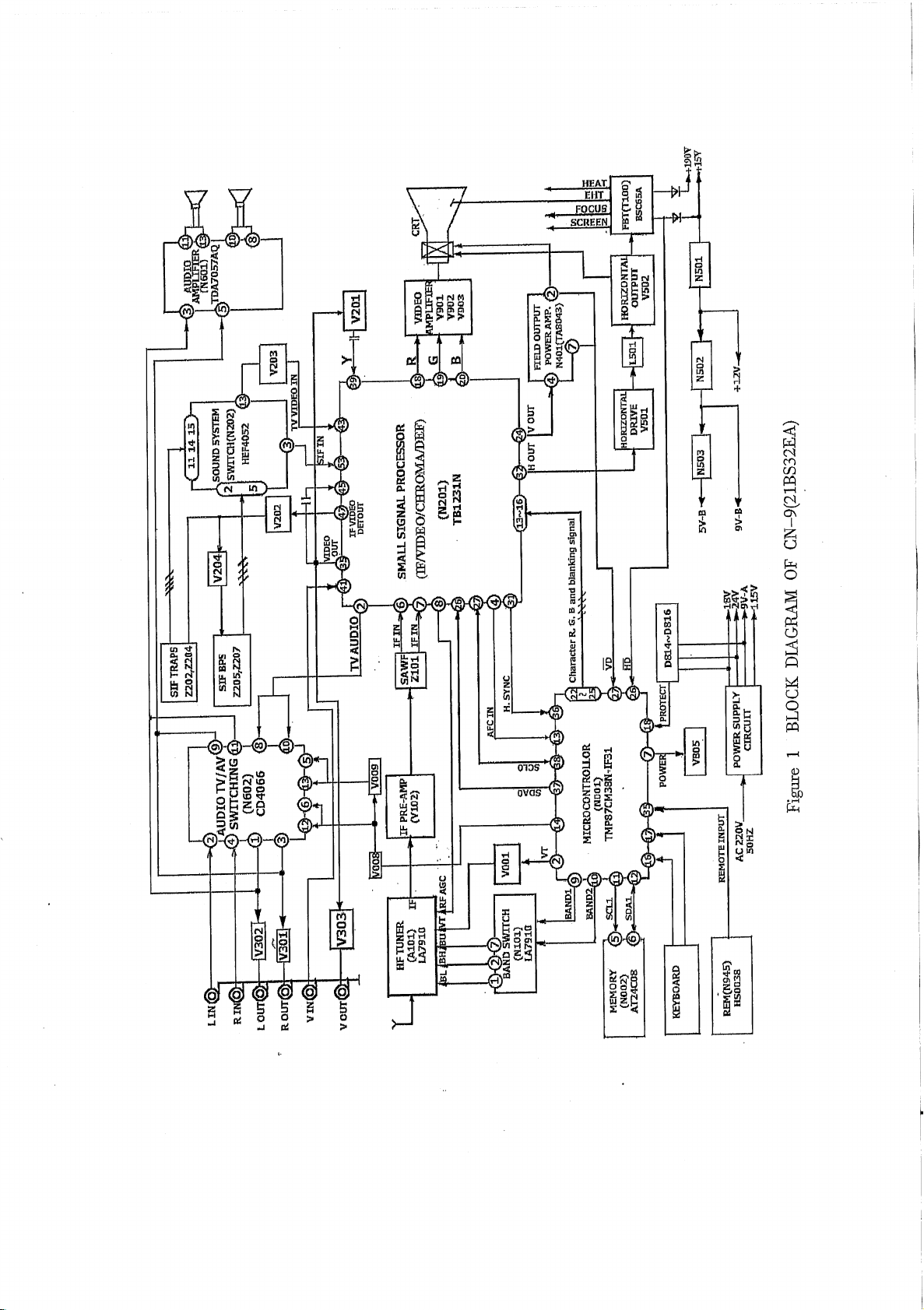
GENERAL DESCRIPTION
CN-9 is a CTV monolithic chassis. It introduces a monolithic IC TB1231N to carry out all the small
signal processing. TB1231N is a kind of IC used by color TV in PAL/NTSC system, which is
controlled by Inter IC Bus. Together with the SECAM decoder TA1275Z, it can form a signal
processing circuit for multi-system color TV. This chassis is used in many fashionable TV receiver
technologies, which makes the performance/price reach the advanced level of the world.
Figure 1 shows the block diagram of CN-9.
Table 1 provides CN-9 mainly ICs and functions.
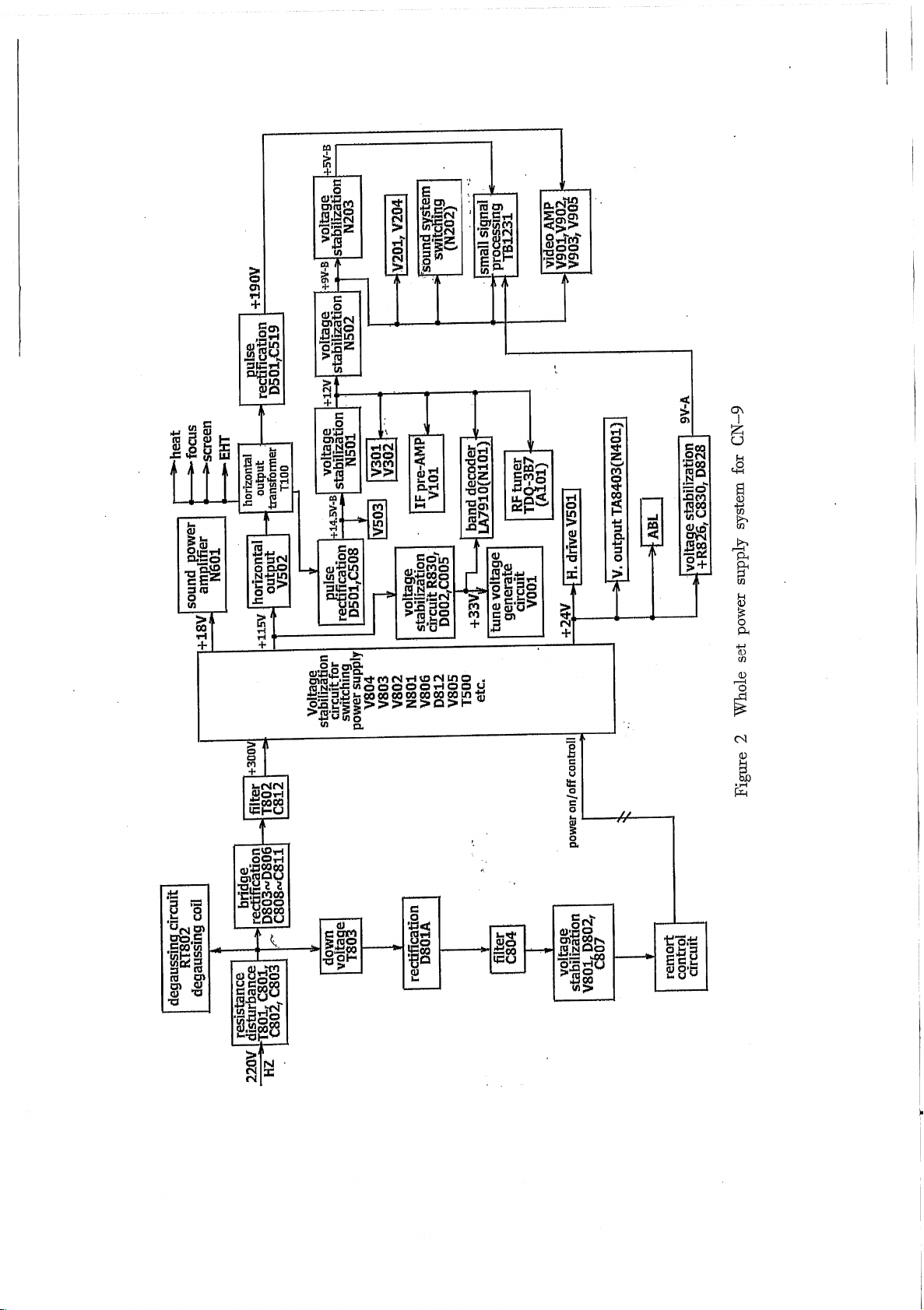
Figure 2 shows the whole set power supply system for CN-9
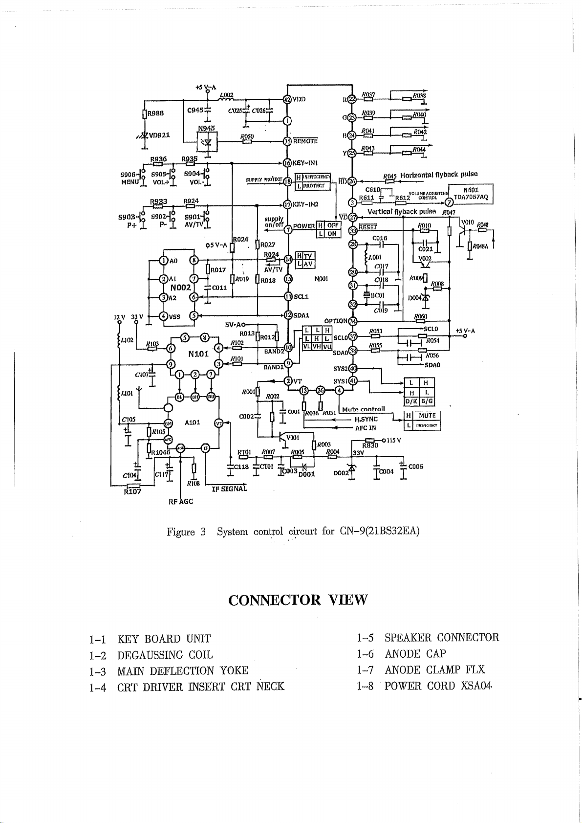
Figure 3 shows the system control circuit of CN-9
Table 1: CN-9 mainly ICs and functions
Location Type Mainly function
N001 CH0807(TMP87CM38N-3673) System control microprocessor
N002 AT24C04 Memory
N945 HS0038 Remote control receiver
NM01 TC9028F-022 Remote control transmitter
N101 LA7910 Band decoder
N202 HEF4052 Sound system switching
N201 TB 1238AN Small signal processing
N401 TA8403 Vertical output power amplifier
N601 TDA7057AQ Audio power amplifier
N602 CD4066 Audio TV/AV switching
Model No: CT-21CH9N
Version 1.0
11
SAFETY INSTRUCTION
WARNING: BEFORE EXAMINING AND SERVICING THIS CHASSIS, READ CAREFULLY
THE FOLLOWING SAFETY INSTRUCTIONS.
X-RAY RADIATION PRECAUTION
1. The EHT must be checked every time the receiver is serviced to ensure that the CRT does not
emit X-ray radiation as result of excessive EHT voltage. The nominal EHT for this receiver is
27.5kv at zero beam current (minimum brightness) operating at AC 220V. The maximum
EHT voltage permissible in any operating circumstances must not exceed 30KV. When
checking the EHT, use the High Voltage Check procedure in this manual using an accurate
EHT voltmeter.
2. The only source of X-RAY radiation in this receiver is the CRT to prevent X-ray radiation you
should use the same type of CRT when replacing it.
3. Some components used in this receiver have safety-related characteristics preventing the CRT
from emitting X-ray radiation. For continued safety, replacement component should only be
made after referring the Product Safety notice below.
SAFETY PRECAUTION
1. The high voltage in the TV reaches to 27.5KV when the TV is in operation. Be more careful
during opening the back cover.
a. The high voltage existing in the TV is very dangerous. Refer servicing to qualified
personnel only.
b. Before removing the high voltage cap, discharge the anode of the CRT and the chas-
sis in case of electric shock.
c. Wear a pair of goggles when handling the CRT to void broken pieces damaging your
eyes.
d. Do not hold the CRT neck in case of causing damage to the CRT.
2. When the power cord needs replacing, use the same one as stated in this manual.
3. Voltage exists between the hot and cold ground when the TV is in operation. Install a
separation transformer during repairing or connecting to any tester for the sake of safety. The
power of the separation transformer should be beyond rated overall power.
4. When replacing a burnout fuse, use the one with the same specifications as the original.
5. When replacing old wire, wind new one round the shaft to weld. When replacing components
with safety in performance, use the same type as that specified by this manual and install it in
the former way.
6. Never place wire near high-temperature or high-voltage components.
SAFETY CAUTIONS FOR PRODUCTS
Many electric and mechanical components in CN-9 chassis have special, safety performances, which
are always neglected. Even if replacing them with some components with the same voltage and power,
you can not get effective protection to X-ray. In the circuit diagram, these special electric components
are indicated by the special mark ! , and on the shadow. When replacing any of them, use the one with
the same specifications as the originals. Otherwise, it may cause X-ray radiation and damage to overall
safety.
Model No: CT-21CH9N
Version 1.0

12
CIRCUIT ADJUSTMENTS
GENERAL INFORMATIONS
All adjustment are thoroughly checked and corrected when the receiver leaves the factory. Therefore
the receiver should operate normally and produce proper colour and B/W pictures upon installation.
However, several minor adjustments may be required depending on the particular location in which the
receiver is operated.
This receiver is shipped completely in carton. Carefully draw out the receiver from the carton and
remove all packing materials. Power cord into a convenient 220 volts 50 Hz AC two pin power outlet.
Turn the receiver ON. Check and adjust all the customer controls such as BRIGHTNESS, CONTRAST
and COLOUR Controls to obtain natural colour or B/W picture.
AUTOMATIC DEGAUSSING
A degaussing coil is mounted around the picture tube so that external degaussing after moving the
receiver is normally unnecessary, providing the receiver is properly degaussed upon installation. The
degaussing coil operates for about 1 second after the power to the receiver is switched ON. If the set is
moved or faced in a different direction, the power switch must be switched off at least 30 minutes in
order that the automatic degaussing circuit operates properly. Should the chassis or parts of the cabinet
become magnetized to cause poor colour purity, use an external-degaussing coil. Slowly move the
degaussing coil around the faceplate of the picture tube, the sides and front of the receiver and slowly
withdraw the coil to a distance of about 2m before disconnecting it from AC source. If colour shading
still persists, perform the COLOUR PURITY ADJUSTMENT and CONVERGENCE
ADJUSTMENTS procedures.
POWER SUPPLY ADJUSTMENT
CAUTION: +B voltage has close relation to high voltage. To avoid X-ray radiation, +B voltage should
be to +115V.
1. Set RVS01 to the mechanical center and AC power supply to 220-+2V.
2. Connect a digital voltmeter to two pins of C822,' and then turn on the TV.
3. Receive Philips test signal.
4. Adjust RVS01 to make the voltmeter read 115±0.5V.
HIGH VOLTAGE EXAMINATION
CAUTION: No high voltage adjustment should be done in CN-9 chassis.
1. Connect a precise high voltmeter to the second anode of the CRT.
2. Turn on the TV and set the brightness and contrast to minimum (i.e. set beam current of the
CRT to zero).
3. The high voltage tested should be 27.5 ± 0.5KV.
4. Set the brightness to minimum or maximum, and ensure high voltage not beyond limitation of
30KV in any case.
Model No: CT-21CH9N
Version 1.0
13
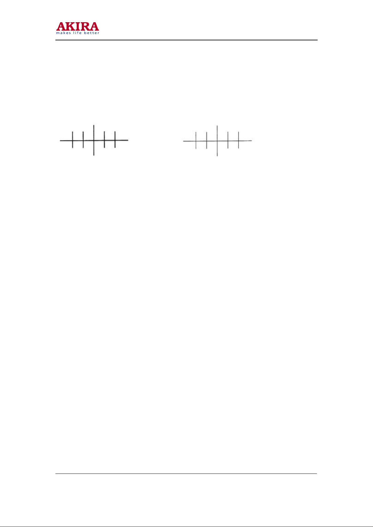
FOCUS ADJUSTMENT
1. Use the remote control to set the contrast to maximum and the brightness, chroma to medium.
2. Set H. V. lines near Philips picture center to thinnest with the focus adjustment potentiometer
on the FBT. After finishing adjustment, ensure that no poor focusing exist near the center or
around of the frame.
Before Adjusting After adjusting
SET-UP ADJUSTMENT
The following adjustments should be made when a complete realignment is required or a new picture
tribe is installed. Perform the adjustments in order as follows:
1. Colour purity
2. Convergence
3. White Balance (See page 17)
Note: The PURITY/CONVERGENCE MAGNET assembly and rubber wedges need mechanical
positioning. Refer to figure 4.
COLOUR PURITY ADJUSTMENT
NOTE: Before attempting any purity adjustment, the receiver should be operated for at least
fifteen minutes.
1. Demagnetize the picture tube and cabinet using a degaussing coil.
2. Set the brightness and contrast to maximum
3. Receive the green raster test signal.
4. Loosen the clamp screw holding the deflection coil and slide, the backward or forward to
provide vertical green belt (zone) in the picture screen.
5. Remove the Rubber Wedges.
6. Rotate and spread the tabs of the purity magnet (See figure 5) around the neck of the picture
tube until the green belt is in the centre of the screen.
7. Slowly move the deflection coil forward or backward until a uniform green screen is obtained.
Tighten the Clamp screw of the coil temporarily.
8. Check the purity of the red and blue raster.
Model No: CT-21CH9N
Version 1.0

15
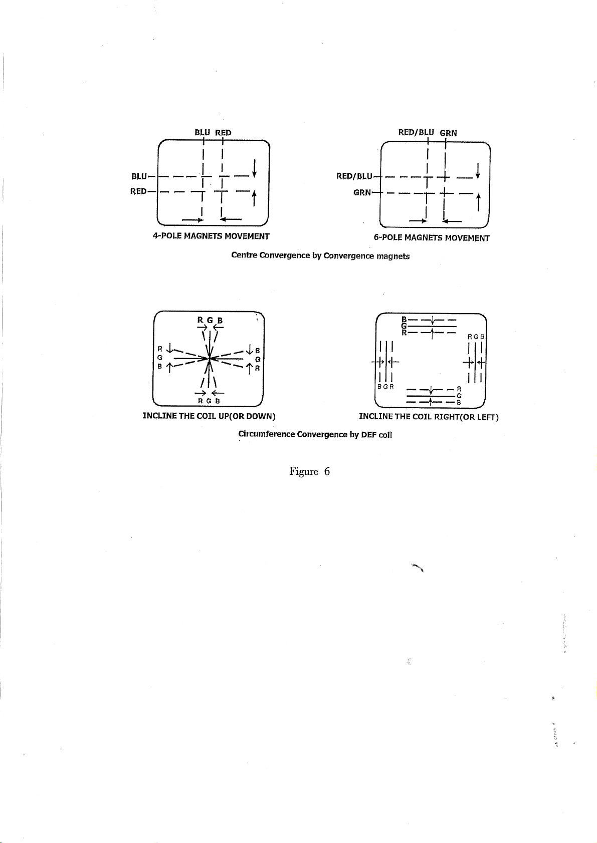
CONVERGENCE ADJUSTMENTS
NOTE: Before a attempting any convergence adjustments, the receiver should be operated for at
least fifteen minutes.
CENTRE CONVERGENCE ADJUSTMENT
1. Receive the pane pattern test signal.
2. Set the brightness and contrast for well-defined pattern.
3. Adjust two tabs of the 4-Pole Magnets to change the angle between them (See figure 5) and
superimpose red and blue vertical lines in the centre area of the picture screen.
4. Turn the both tabs at the same time keeping the angle constant to superimpose red and blue
horizontal lines at the centre of the screen.
5. Adjust two tabs of 6-Pole Magnets to superimpose red/blue line (land green line. Adjusting
the angle affects the vertical lines and rotating both magnets affects the horizontal lines.
6. Repeat adjustments 3, 4, 5 keeping in mind red, green and blue movement, because 4-Pole
Magnets and 6-Pole Magnets have mutual interaction and make dot movement complex.
CIRCUMFERENCE CONVERGENCE ADJUSTMENT
1. Loosen the clamping screw of defection coil slightly to allow the coil to tilt.
2. Temporarily put a wedge as shown in figure 4. (Do not remove cover paper on adhesive part
of the wedge.)
3. Tilt front of the deflection coil up or down to obtain better convergence in circumference. (See
figure 6) Push the mounted wedge into the space between picture tube and the coil to fix the
coil temporarily.
4. Put other wedge into bottom space and remove the cover paper to stick.
5. Tilt front of the deflection coil right or left to obtain better convergence in circumference. (See
figure 6)
6. Keep the deflection coil position and put another wedge in either upper space. Remove cover
paper and stick the wedge on picture tube to fix the coil.
7. Detach the temporarily mounted wedge and put it in another upper space. Stick it on picture
tube to fix the coil.
8. After fixing three wedges, recheck overall convergence. Tighten the screw firmly to fix the
coil and check the coil is firm.
9. Stick three adhesive tapes on wedges as shown in figure 4.
SERVICE MODE GENERAL INSTRUCTIONS
1. ENTERING TO SERVICE MODE
Use the user remote receiver K10 seriers. Set the volume to minimum. Press the MUTE button on
Remote Control. Keep pressing the MUTE button, press MENU button on TV set until the
character D and an adjustment item appears on the screen.
2. SELECTING THE ADJUSTING ITEMS
Every pressing of the MENU “ ” or “” button on remote control transmitter changes the
adjustment items in the following BUS DATA table.
Model No: CT-21CH9N
Version 1.0
 Loading...