

Page 1

Projection TV
Service Manual
Page 2

-2 -
MODEL:
PTV-50H08
Model No.: PTV-50H08
Version: 1.0
Page 3

-3 -
CONTENTS
SAFE NOTICE......................................................................................................................................... 4
SPECIFICATION..................................................................................................................................... 7
TV SET OVERVIEW............................................................................................................................... 8
MAINTENANCE ADJUSTEMENT ....................................................................................................... 9
NOTICE FOR MAINTENANCE .......................................................................................................... 21
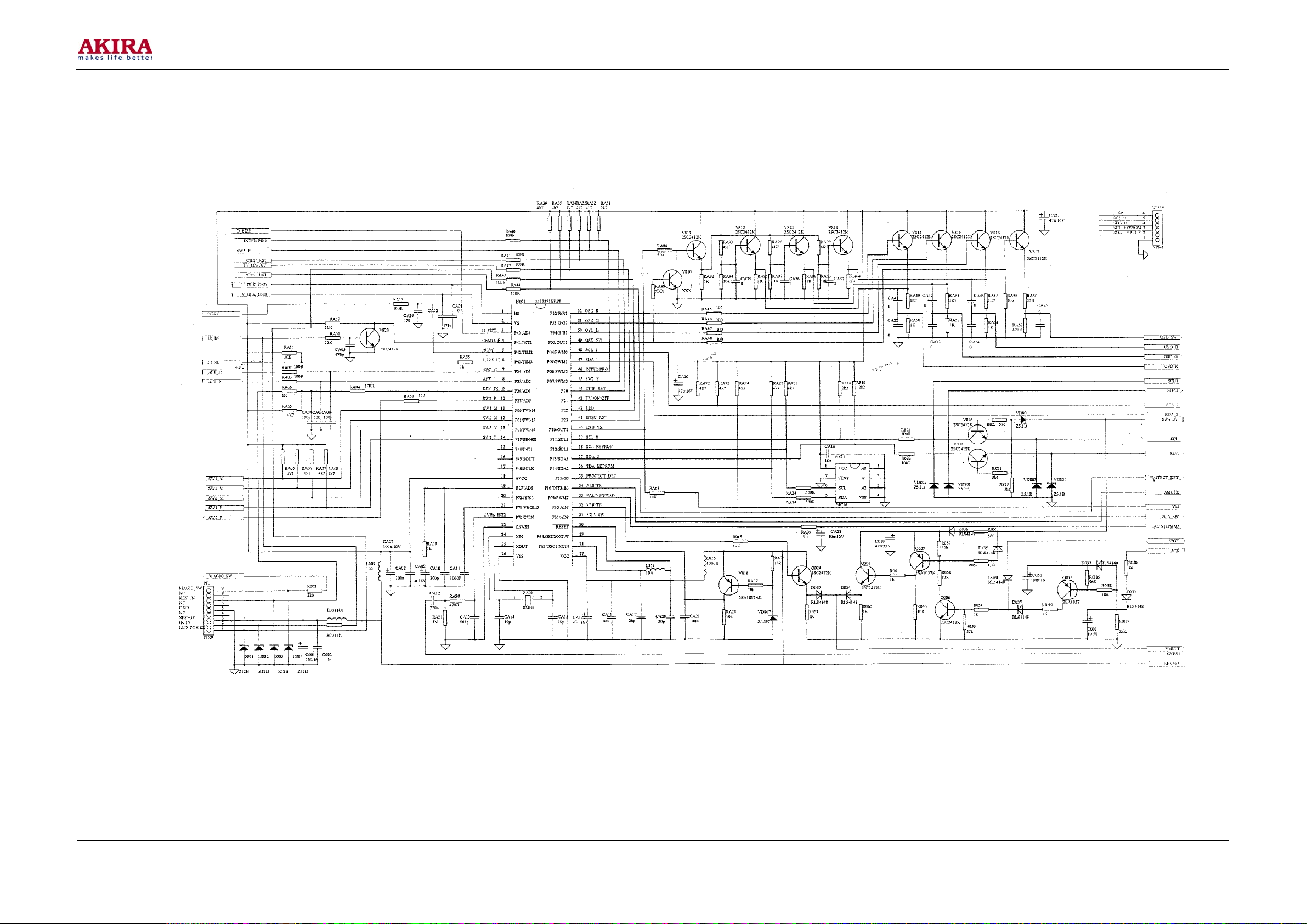
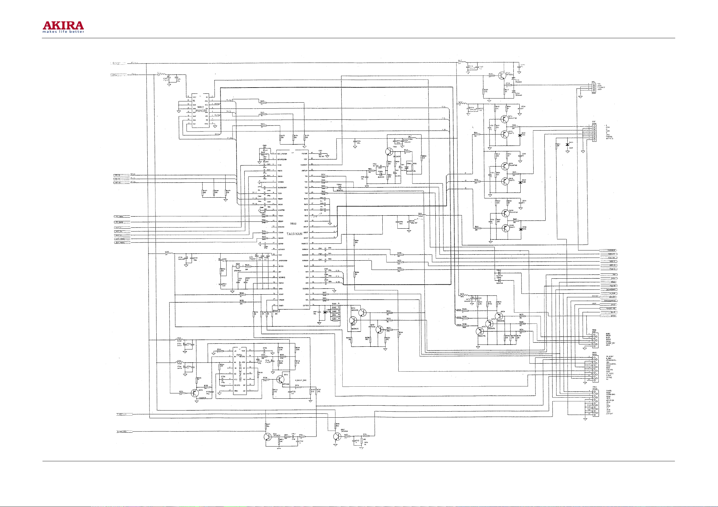
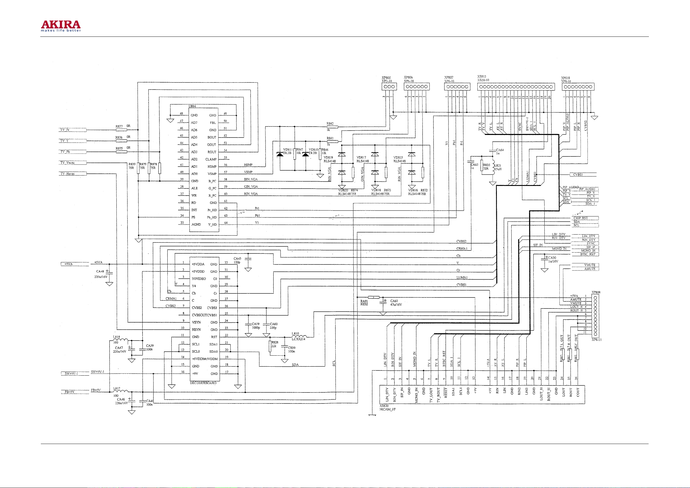
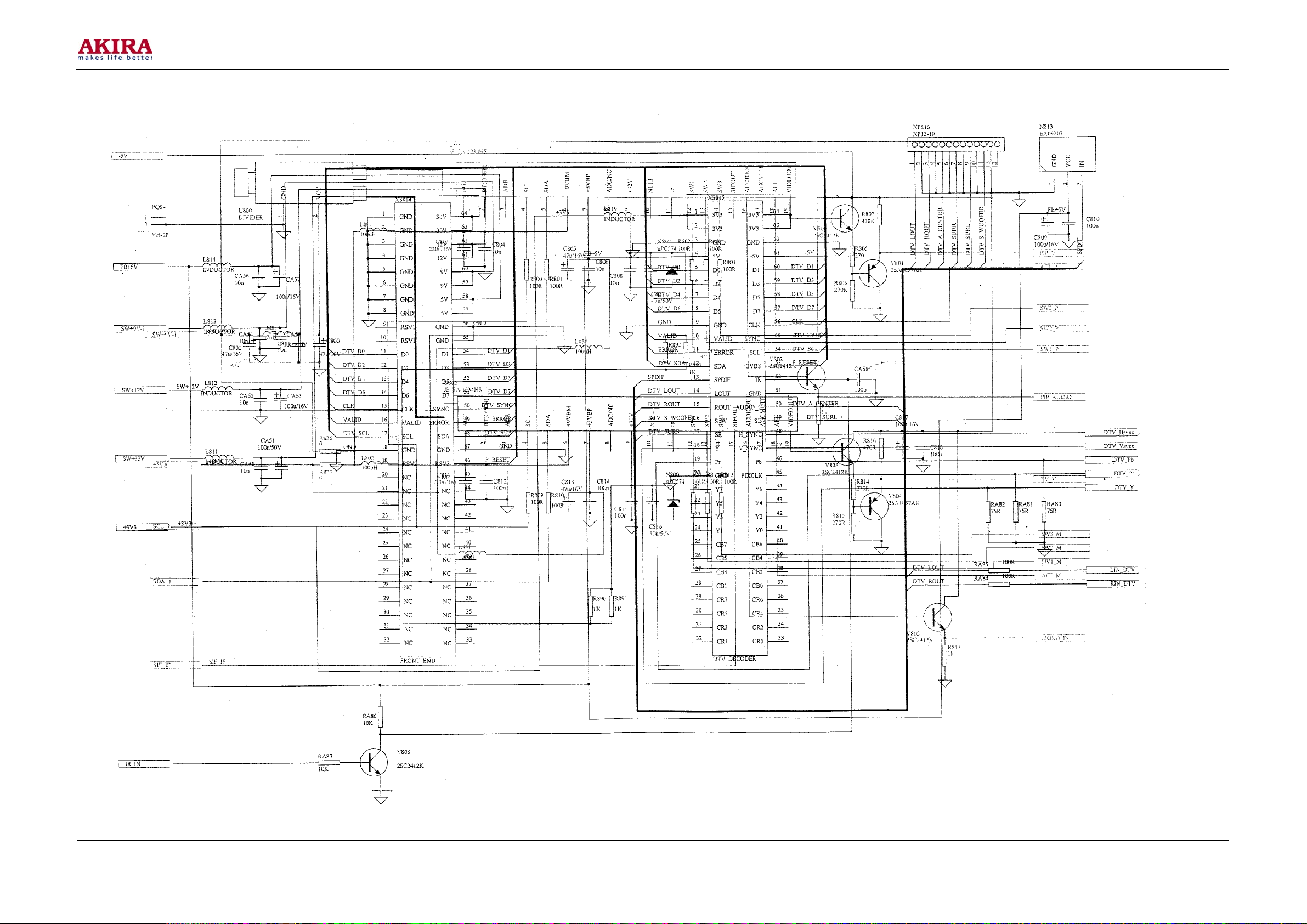
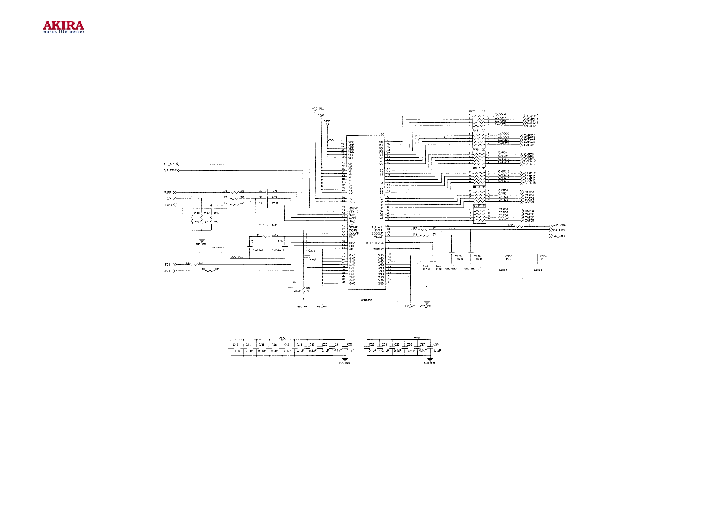
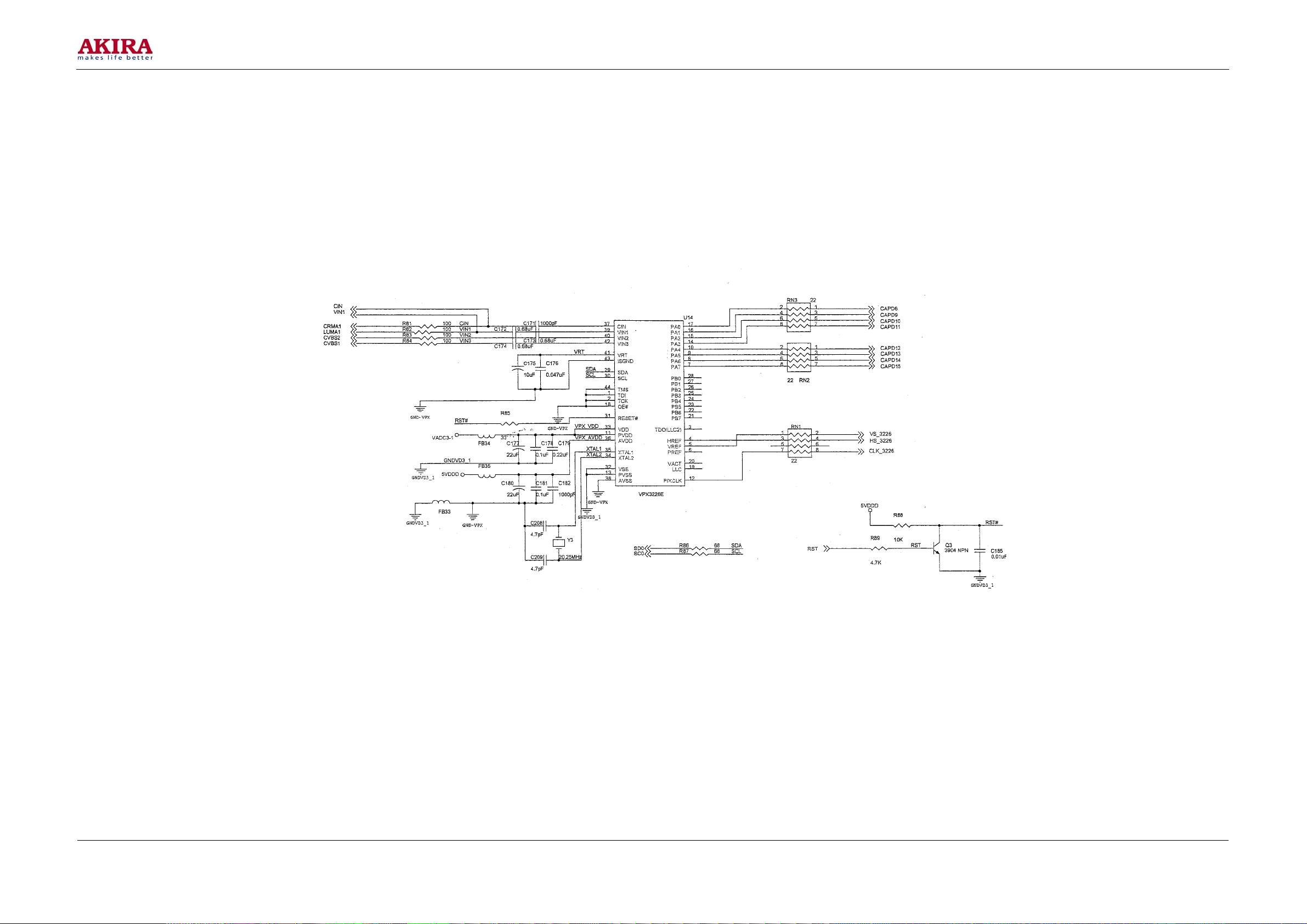
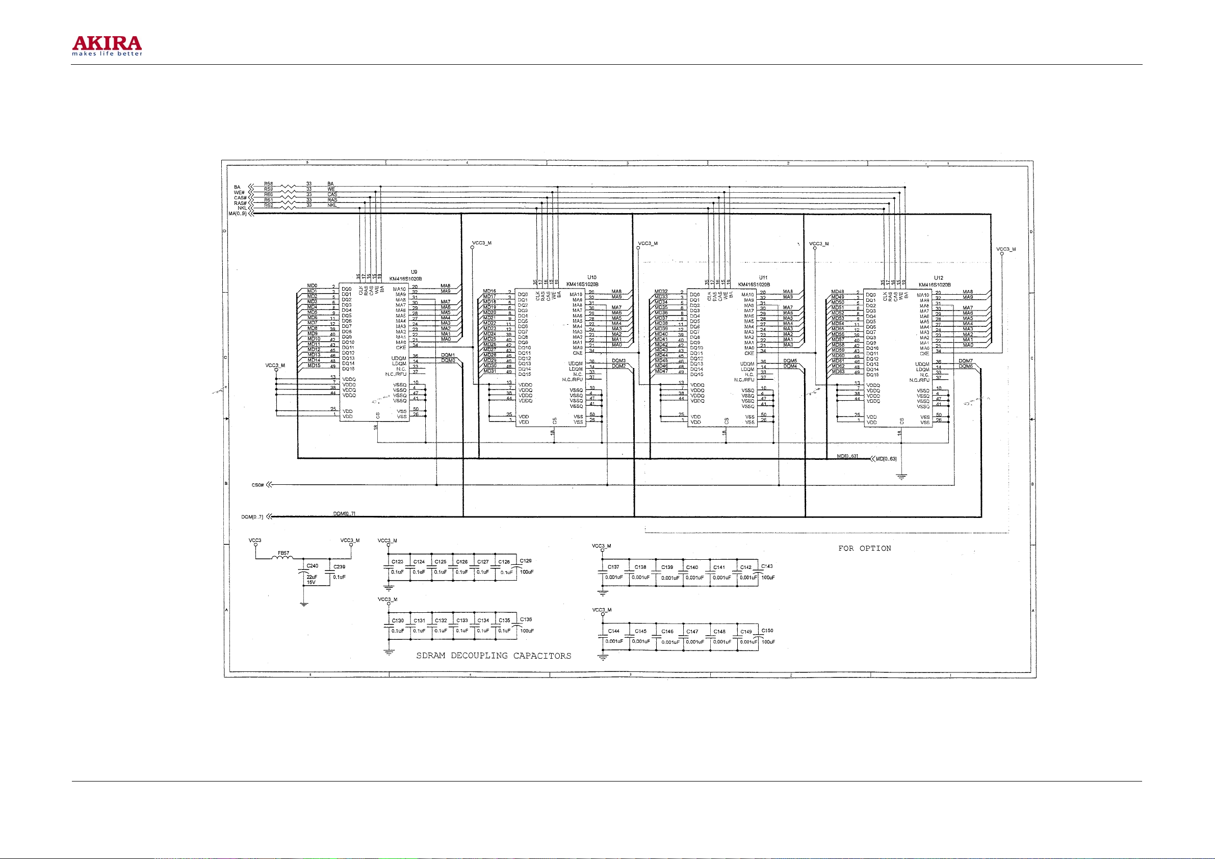
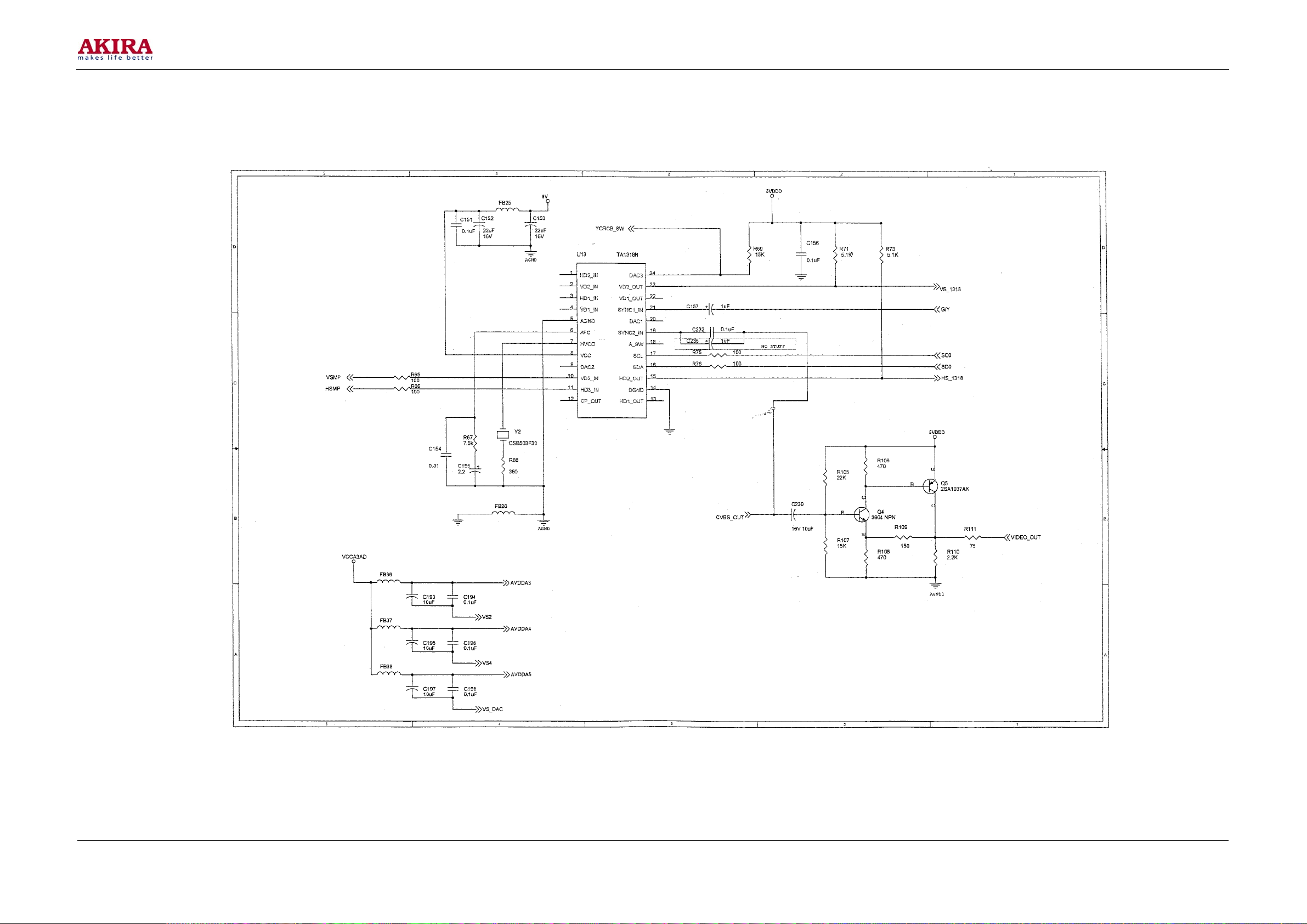
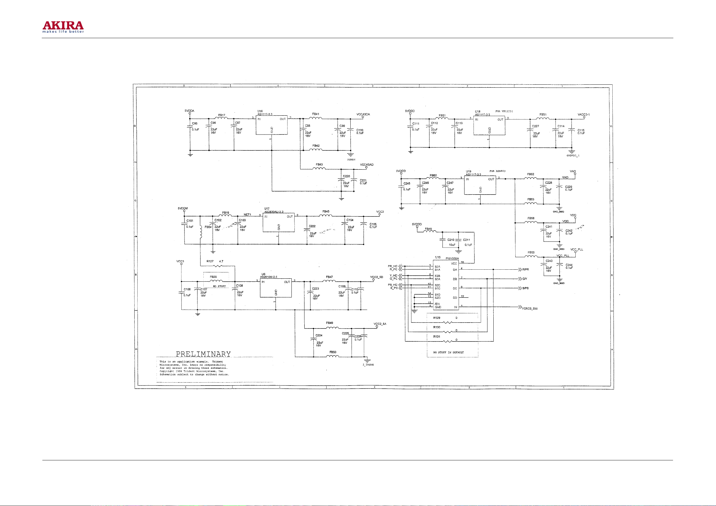
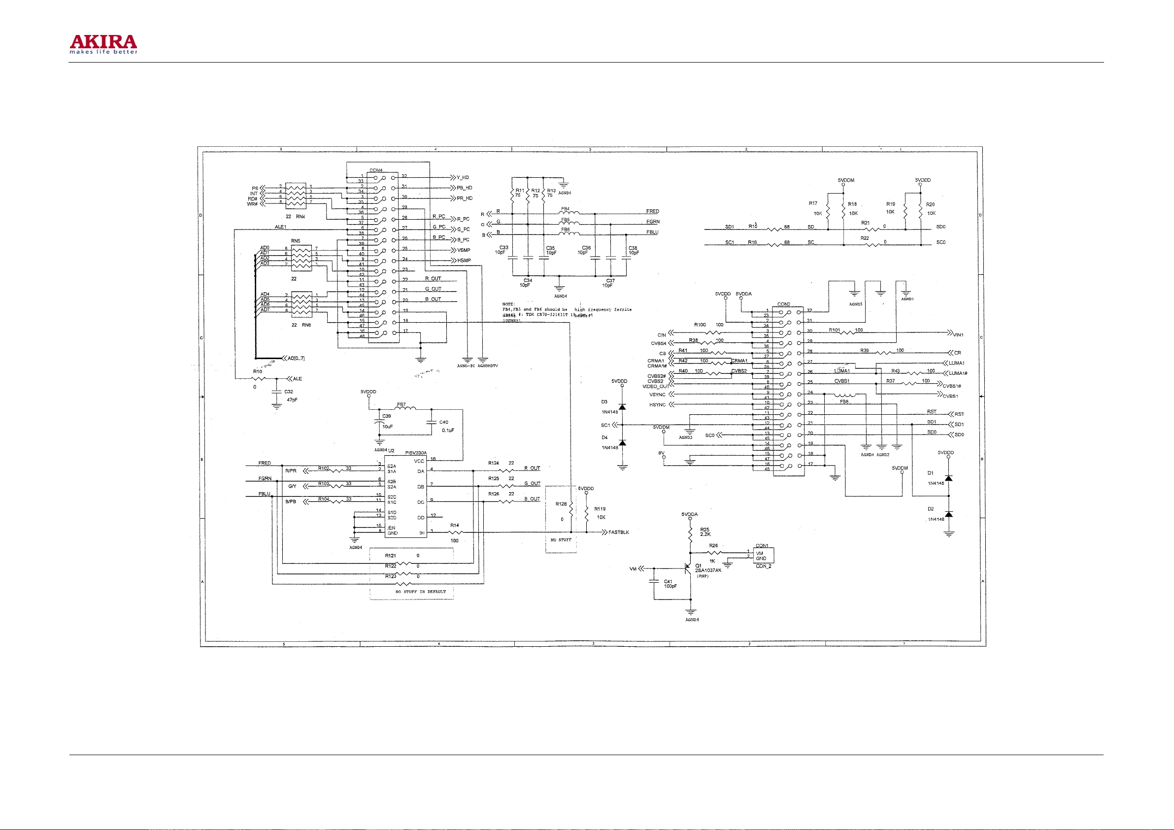
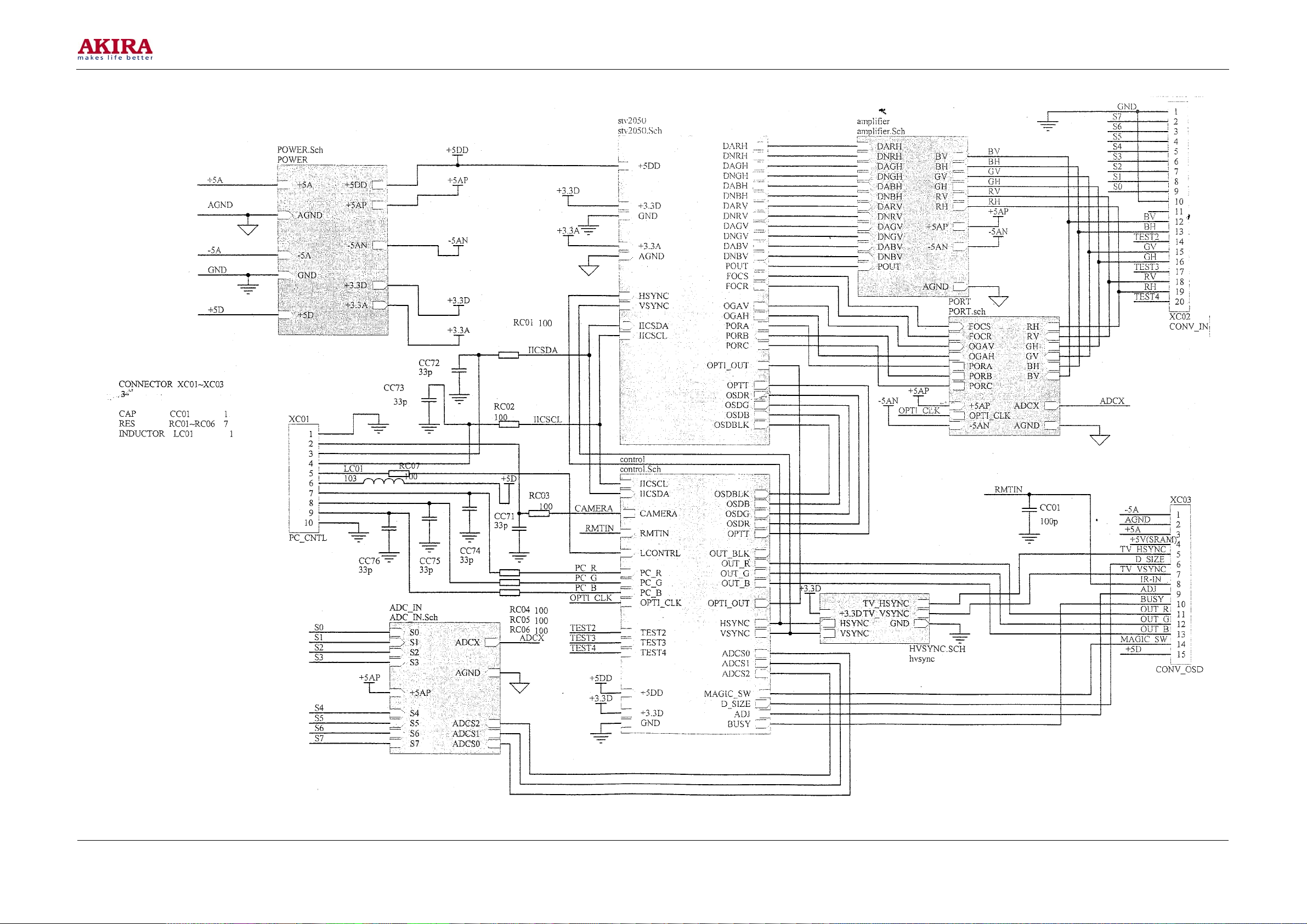
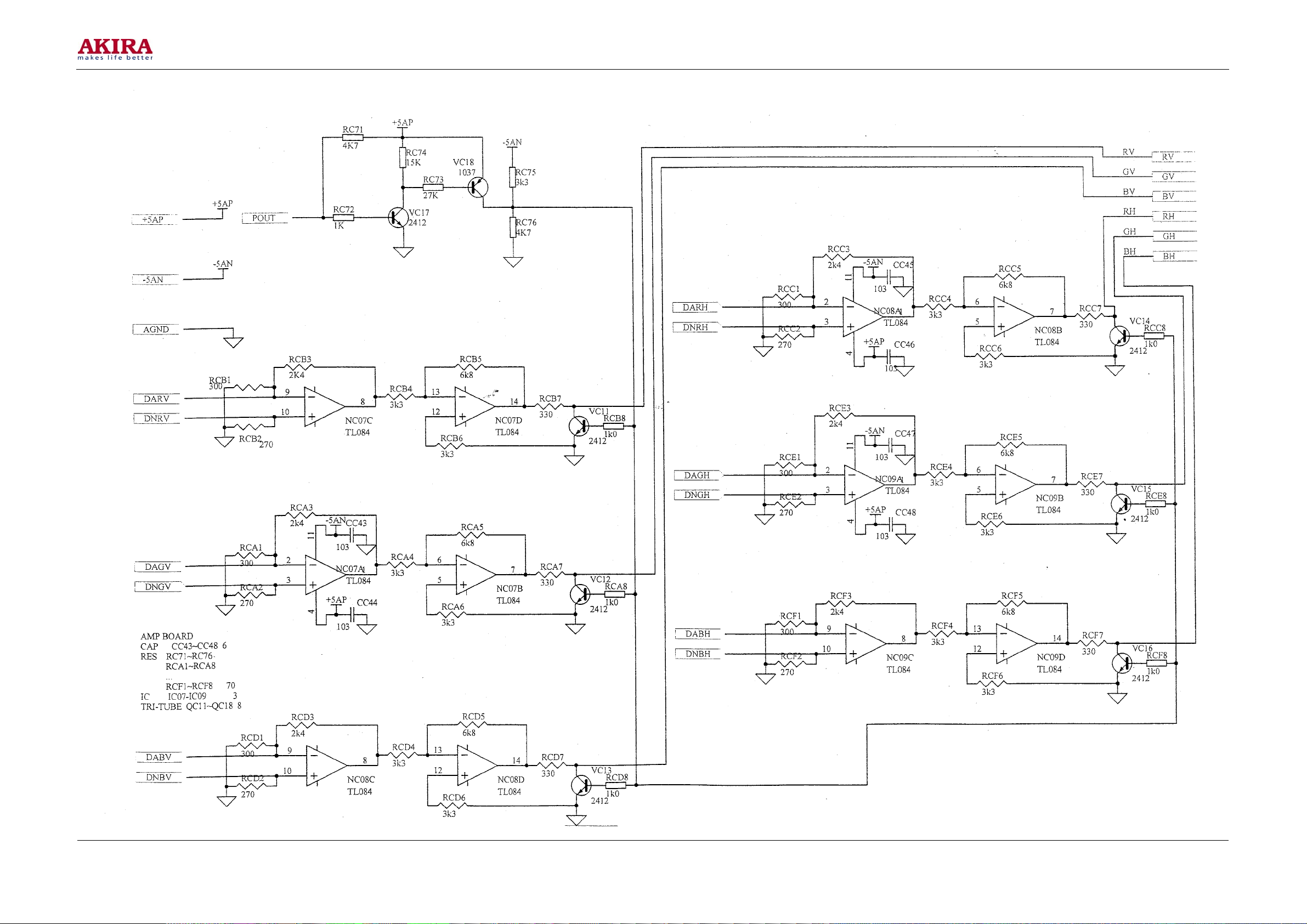
CIRCUIT DIAGRAM............................................................................................................................ 35
Model No.: PTV-50H08
Version: 1.0
Page 4
-4 -
SAFETY NOTICE
Use an insolating transformer during maintenance.
In this manual and the parts list of its annexed tables as well as the schematic circuit diagram, those
components with special safety functions are marked with “ ! ” need paying special attention upon
maintenance. Maintainers shall carefully read the “Safety Notices” and “Safety Precautions” in the
manual before maintaining the TV set core.
Important: In case the projection tube is replaced, only the same model or an equivalent model certified
by “CB” shall be used to ensure the protection function to the X-ray.
The maintenance of this product is only applicable to the qualified maintenance technicians, which
means that unauthorized maintenances are forbidden. The qualified technicians shall have necessary test
equipment and special tools, and shall have been trained with those complicated products said in this
manual to have the ability to maintain safely such complicated products as the projection TV set said in
this manual.
Improper maintenance may affect the safety and reliability of the product. If you are not qualified to
maintain the product, never take a risk trying to maintain it, find a qualified maintainer to maintain it
instead.
W a r n i n g
When maintain or handles the circuit plank to imply with the other a piece that soldering lead feet,
should avoid the soldering getting in touch with skin directly. At the same time, notice and do not
inhale welding a creation any smoke or airs.
Safety Precautions
1 Check and test the complete TV set maintained for safety before handing it to the costumer. The
items to be checked and tested are as follows:
a. Make sure that the safeguard devices and parts are in good condition, and not removed during
the maintenance.
i. The safeguard devices and parts of this TV set core for protecting the technicians and
costumers shall be all reinstalled properly, including those removed for maintenance
convenience.
ii. Always operate the TV set with all the safeguard devices and parts reinstalled properly
after the reassembly of the TV set core and other assemblies.
iii. Any maintenance negligent of the safety precautions or without safety check and test
may cause dangers.
Model No.: PTV-50H08
Version: 1.0
Page 5

-5 -
b. Make sure there are no gaps with the shell so as to prevent adults and children from putting
fingers inside and touching the dangerous voltage. The gaps include but not limited in:
i. Gaps with the front frame are too large.
ii. The back cover is not installed properly or correctly.
c. Test of antenna cold junction: Connect the two pins of the TV set plug with a piece of
conductor, with the TV set switched on. Connect one end of the ohmmeter to the pin of the plug,
and the other end to the antenna input terminal of the tuner or the bare screw. Connect to the
coaxial cable if possible. If the resistance is less than 8 ohms or greater than 11 ohms,
abnormalities must exist, which shall be removed before the TV set is submitted to the
costumer. Repeat the above test with the TV set switched off.
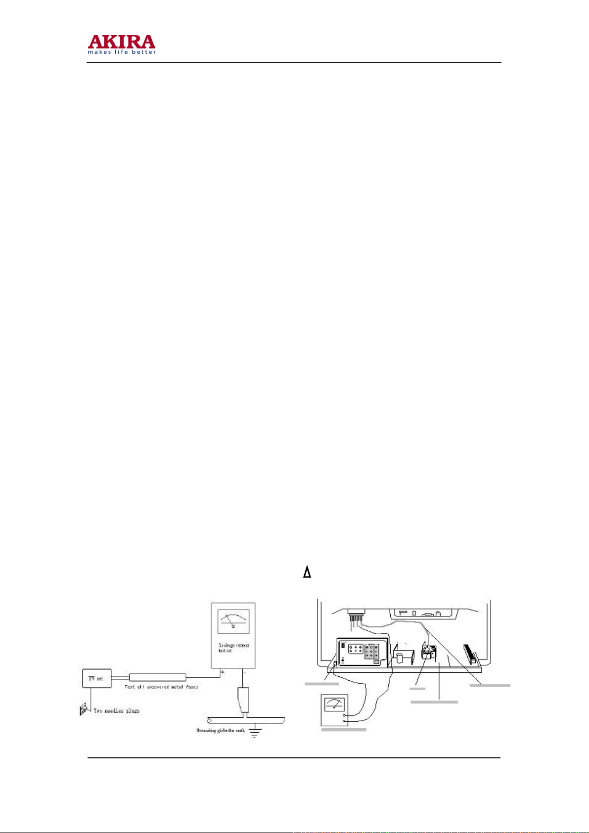
d. Leakage current test: After the reassembly, insert the mains plug of the TV set into a 40Vsocket
(Do not use an insolating transformer during the test. The test connection is shown in Fig.1.).
Test with a leakage current meter or test system first with the switch on, then with the switch
off. Test the leakage current of the known groundings (metal pipes) to each of the bare metal
parts (the antenna, the knob supports, the metal front frames, the screw ends, the metal covers,
the control buttons, etc.) of the TV set, especially the bare metal parts connected to the core.
None of the currents shall be more than 0.7mA. Repeat the same tests with the polarity of the
plug exchanged. Any leakage current values beyond the limits may cause electric shocks, which
shall be tackled before returning the TV set to the costumer or connecting antenna or
accessories to it.
e. A high voltage limiting circuit (HVLC)is equipped with the TV set to control the high voltage
under the set value. Upon maintenance, do as specified in all the notes of the maintenance
manual, and the HVLC will function properly.
f. Maintenance warnings: At the largest contrast ratio, the high voltage of the TV set is lower than
31.0kV. In case parts affecting the high voltage are replaced, verify whether the high voltage of
the TV set is lower than 31.0kV at the largest contrast ratio. Use a voltage meter with a large
resistance and anti high voltage, to measure the high voltage. Connect the negative pole to the
grounding of the TV set core, and the positive pole to the high voltage connector. the connection
of the high voltage meter is shown in Fig. 2.
Note: Always turn off the powers of the TV set and the high voltage meter before connecting the positive
pole.
g. The X-rays (projection tube): The X-rays generated by the TV set are mainly from the
projection tube. Therefore the TV set takes use of the above said functions to reduce the
radiation hazard of the X-rays. In case the projection tube is replaced, only the same model or an
equivalent model certified by “CB” shall be used to ensure the protection function to the X-ray.
While troubleshooting or testing the TV set, avoid getting close to the projection tube and the
high voltage parts. Never run the TV set core for a very long time when troubleshooting the
causes of over high voltage.
Model No.: PTV-50H08
Version: 1.0
Page 6
-6 -
2 Carefully read and follow the warnings and safety precautions on the receiver shell, the core and the
projection tube.
3 Warnings on design modification: Never modify or supplement the mechanical or circuit design of
the TV set. Circuit modification and suc h supplement as the assistant audio/video output adapter
may alter the safety performance of the TV set and injure the users.
4 Warnings on anti-explosion of the projection tube: the projection tube of the TV set uses a complete
explosion protection design; use the same model of projection tube upon replacement. Always wear
a pair of goggles when moving, installing or handling the projection tube. While handling the
projection tube, keep persons without goggles away from it. Put the projection tube at a place away
from people. Never handle the projection tube by the tube neck.
5 Warnings on the hot core: usually maintain a hot core with an isolating transformer connected to
assure safety. The energized end of the mains circuit of a cold core is connected to the AC mains,
therefore maintenance shall also be made with an isolating transformer connected for better safety.
6 Pay attention to the original lead covers, especially those in the following areas, to assure proper lead
covers:
a. The area near to sharp edges.
b. The area near to hot parts. Make sure that the leads do not touch the hot parts.
c. The AC mains.
d. The high voltage.
e. The antenna cable.
Check all the areas for the pressed, pulled or injured cables; don not alter the space between every
two components and printed circuits; check the AC mains cable for damage.
7 Replace over heated or damaged components, parts or cables with new ones of the original
specifications. In addition, find the causes to be over heated or damaged, and if necessary, take
proper measures to eliminate any hidden dangers.
8 Safety precautions to the parts: many electronic and mechanical parts of the TV set have special
safety functions, some of which cannot be observed from their appearances. Although other parts
with high voltages or greater power can be used instead, the safety performances of those parts still
cannot be assured. The components marked with “ ! ” have special safety functions. Always Replace
these parts with those recommended in the replacement part list to avoid such dangers as electric
shocks and fires.
Fig.1 Fig.2
Model No.: PTV-50H08
Version: 1.0
Page 7
-7 -
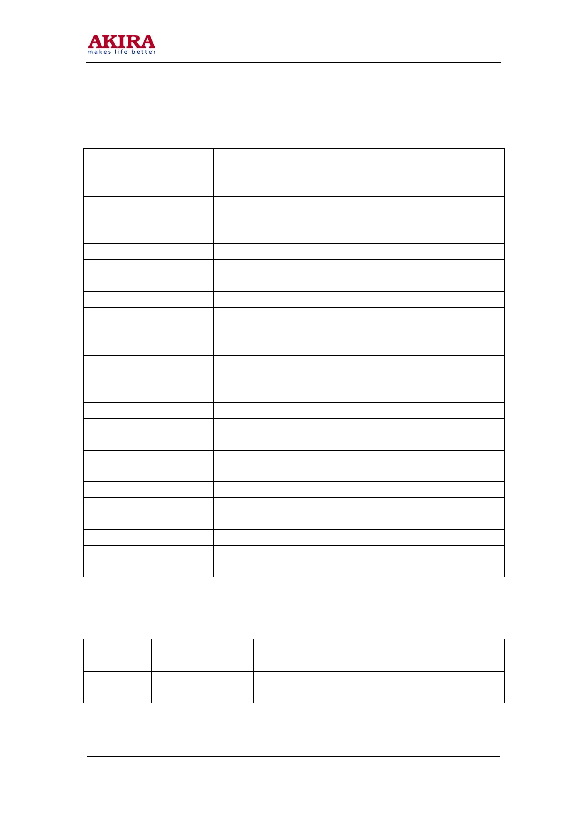
SPECIFICATION
Screen size 50”
Projection tube 7” (P16LXL00 / P16LSG03)
Lens D250 (R/G/B)
Anode high voltage 30.2kV
Mains voltage 175 – 250VAC; 50/60Hz
Power consumption 250W
Receiving system PAL D/K, B/G, I; SECAM D/K, B/G, L/L
Frequency ranges E2 – E9, S10 – S41, S38 – DS57
Antenna input 75 Ω imbalanced input
Number of channels 200
Audio output 12WX2
Comb filter 3D digital comb filter; PAL/NTSC system
Digital convergence Yes
NICAM receiving Yes
Teletext Yes
BBE Yes
SRS Yes
S-VIDEO input terminals One side set and one back set
Video input terminals One side set and two back sets
Chromatic deviation input
(YprPb/YcrCb)
Audio (L/R) input terminal One site set and two back sets
Earphone output jack One on side
Video output terminal One back set
Weight 62kg
Dimension W x H x D 1260mm x 1480mm x 745mm
Screen shielding Yes
Protector
Protector Specification Circuit protected Chassis with the protector
F908 RT1-20-4A AC mains circuit Secondary mains board
FP01 RT1-20-3. 15A Primary mains circuit Mains deflexion board
F902 RT1-20-3. 15A Secondary mains circuit Secondary mains board
One back set
Model No.: PTV-50H08
Version: 1.0
Page 8
-8 -
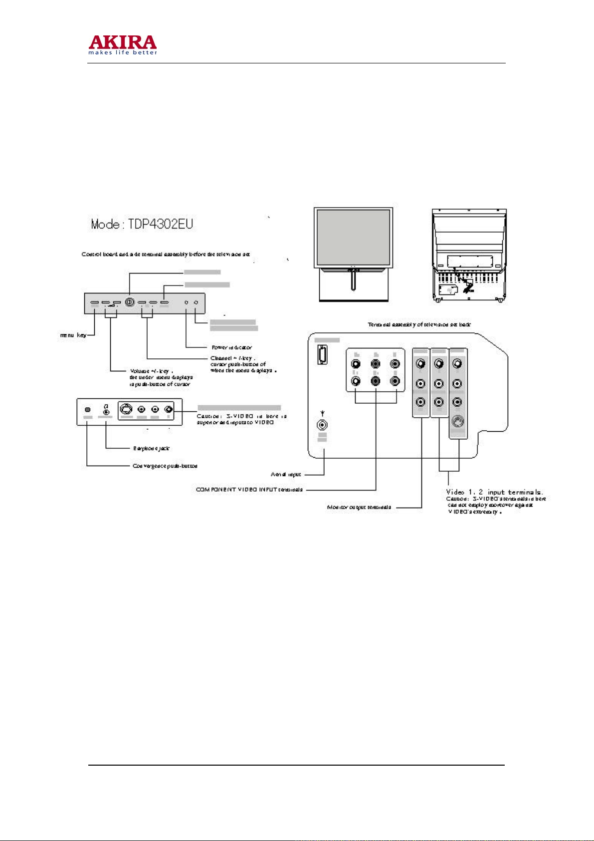
TV SET OVERVIEW
Model No.: PTV-50H08
Version: 1.0
Page 9

-9 -
MAINTENANCE ADJUSTMENT
Adjustment Methods
1 How to enter the “M” status: with the MENU key pressed, press keys MUTE and TXT on the
remote controller successively
How to leave the “M” status: press the channel plus key on the front panel.
2 How to enter the aging status: At the “M” status, press Key Recall on the remote controller to enter
the aging status; now the “M” sign shows red.
How to leave the aging status: press Key Recall on the remote controller for more than two seconds
to leave the aging status; now the “M” sign shows green again.
3 How to enter the status of a bright line: At the “M” status, press Key Still on the remote controller to
enter the status of a bright line, and press Key Still on the remote controller once more to leave the
status of a bright line.
4 How to enter the status of geometry linearity adjustment: In the TV mode, with Key SK01 pressed,
press Key MUTE on the remote controller to enter the status of geometry linearity adjustment; press
Key SK01 to leave the status of geometry linearity adjustment.
5 How to enter the status of under convergence adjustment: Turn on the TV set with Key SK01
pressed to enter the status of under convergence adjustment, now the three-color squares displayed
on the screen. Press SK01 or Key CONV on the side panel to exit.
6 How to enter the status of convergence adjustment:
Method One: In the TV mode, press SK01 to enter the status of convergence adjustment.
Method Two: In the TV mode, press Key CONV on the side panel together with Key TV/AV on the
remote controller to enter the status of convergence adjustment.
Press Key SK01 or CONV to exit.
7 How to select the color in the status of convergence adjustment: In the status of convergence
adjustment, press Key picture on the remote controller to switch between colors. The switching
order is: Single green (adjust the green), red + green (adjust the red) and red + blue + green (adjust
the blue); press Key Audio to select the display color.
8 How to select the mode of convergence adjustment: In the status of convergence adjustment, press
Key TXT on the remote controller to select between Modes 13X16 and 5X5.
9 How to move the cursor during the convergence adjustment: Press digital Keys 2 , 4 , 5 , 6 and 8 ,
and the cursor moves as follows:
Digital Key 2-------- cursor up
Digital Key 8--------cursor down
Digital Key 4--------cursor left
Digital Key 6--------cursor right
Digital Key 5--------cursor back to the original center
Model No.: PTV-50H08
Version: 1.0
Page 10
-10 -
10 Data adjustment is the status of convergence adjustment:
Remote controller: Key Channel Plus -------- Data increasing (up)
Key Channel Minus -------- Data reducing (down)
Key Sound Plus >--------- Data increasing (right)
Key sound Minus <---------Data Reducing left
11 Switch between the fine adjustment and the coarse adjustment: In the status of convergence
adjustment, press Key i on the remote controller to switch between the fine adjustment and the
coarse adjustment, with the default mode being the coarse adjustment, and with additional line
adjustment function in the 13X16 mode.
12 How to write the data of convergence adjustment: In the status of convergence adjustment, press
Key Write and confirm the action (press Key Sound to confirm, and Key Mix to quit) to write the
data of the current system into the E2PROM, which will not be lost after power off.
13 How to read the data of convergence adjustment: In the status of convergence adjustment, press Key
Read and confirm the action (press Key Sound to confirm, and Key Mix to quit) to read out the data
of the current system.
14 How to clear the data of convergence adjustment: In the status of convergence adjustment, press Key
Reset and confirm the action (press Key Sound to confirm, and Key Mix to quit) to clear the current
system and the convergence data.
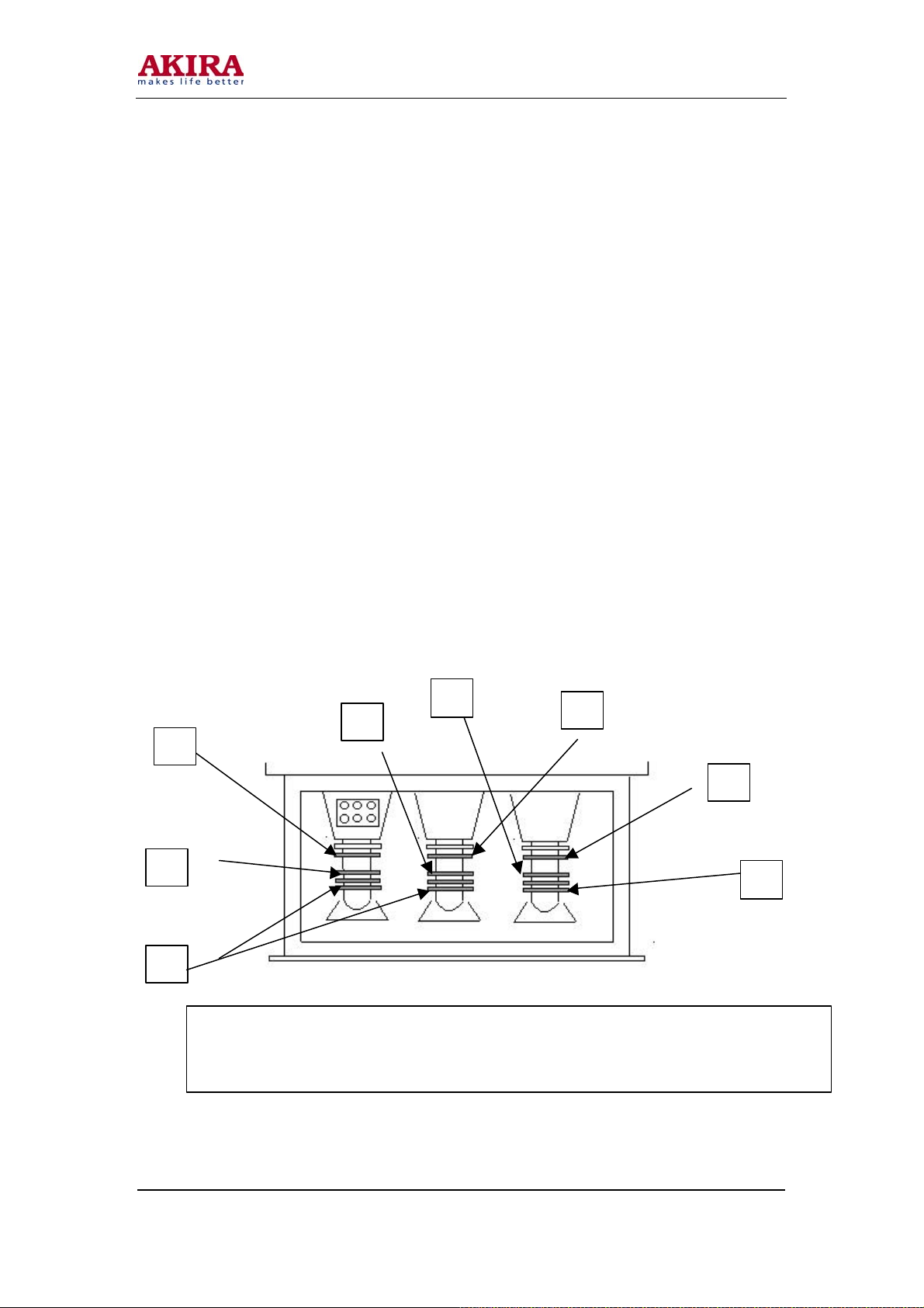
15 Diagram of Adjustment Spots
a. Projection Tube
1
4
5
1.Central Magnetic Sheet of Red Tube 2. Central Magnetic Sheet of Green Tube
3.Central Magnetic Sheet of Blue Tube 4. Four Magnetic Sheets for Beam Shape Adjustment
5. Magnetic Sheet for Beam Alignment Adjustment 6. Focusing Case Assembly
Model No.: PTV-50H08
Version: 1.0
4
4
2
3
5
Page 11
-11 -
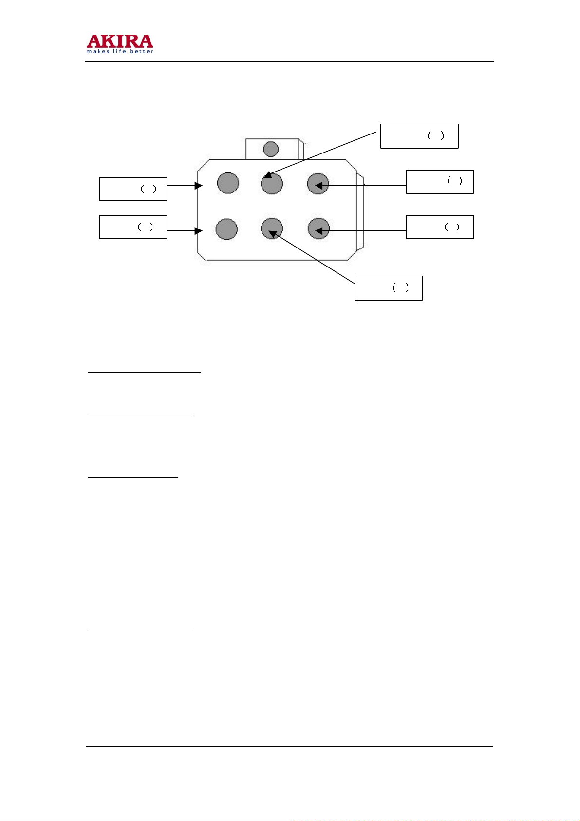
b. The Focusing Case
cut-off R
Focus R
Adjustment procedure
Screen Control (CUT OFF) Adjustment (I2 BUS)
Preparation of Adjustment:
1 The pre-aging has been finished.
2 Turn shield grid potentiometers R, G and B respectively counterclockwise slowly to the status with a
dark picture. (Avoiding the burn of projection tube)
Adjustment Procedure:
1 Enter the “M” status with the remote controller: press Key Still on the remote controller to enter the
status of a bright line.
2 Adjust Clockwise slowly the red, green and blue screen control potentiometers on the focusing
assembly respectively until corresponding bright red, green and blue lines are emerging slightly on
the screen.
3 Press Still to exit the status of a bright line.
4 Press the channel plus key on the front panel to exit the “M” status.
Adjustment on Raster Inclination
Preparation of Adjustment:
1 Place the TV set with its face to the east or west.
2 Let the TV set receive the pane signal of PAL system.
3 Set the contrast to maximum with others medium.
4 Turn on the TV set with Key SK01 pressed to enter the status of under convergence and display the
convergence mesh.
Focusing Case
cut-off G
cut-off B
Focus B
Focus G
Model No.: PTV-50H08
Version: 1.0
Page 12
Blue
-12 -
Adjustment Procedure:
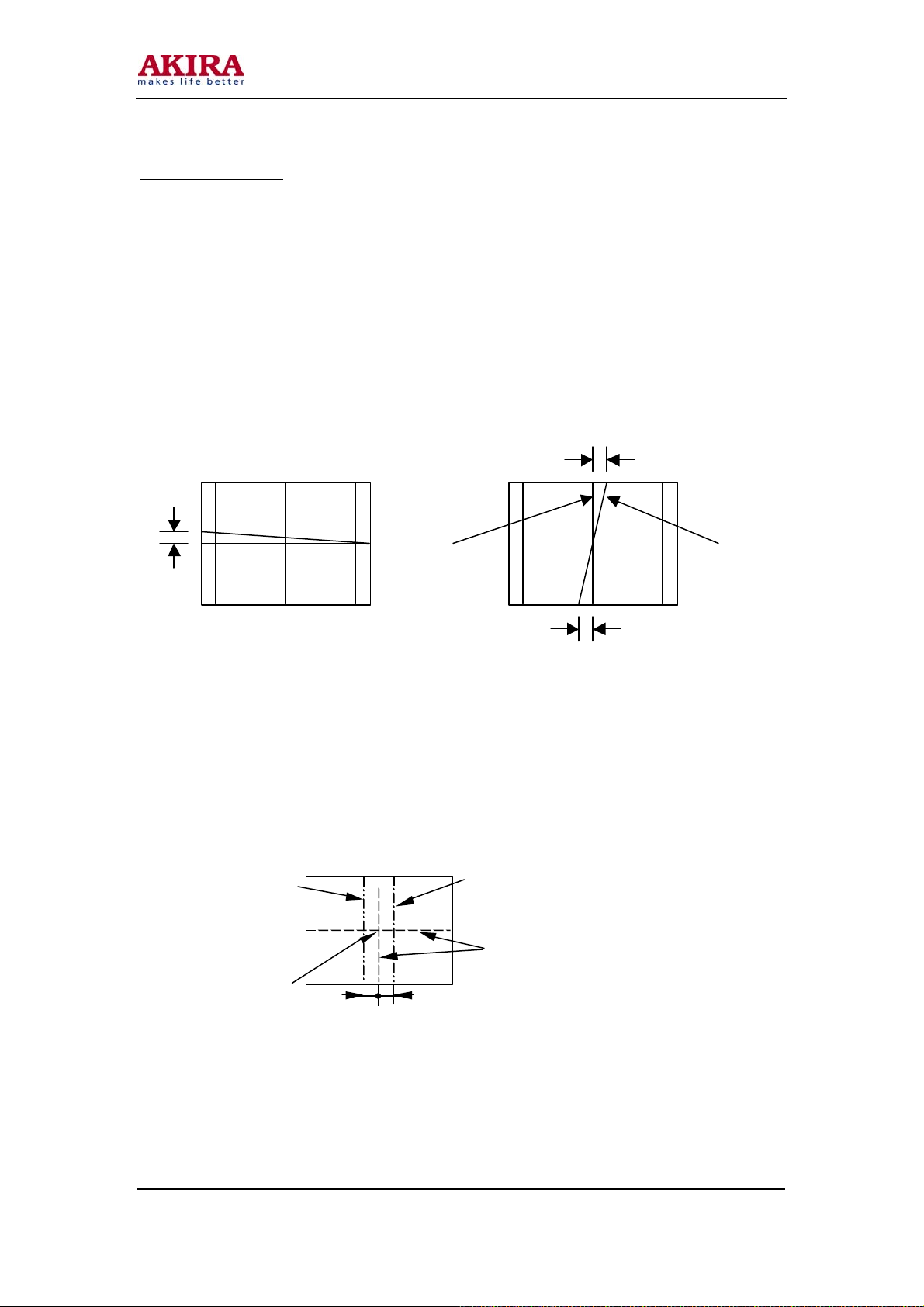
1 Cover the red and the blue projection tubes with the lens covers of the projection tubes to remain
only the green raster on the screen.
2 Adjust the deflecting coil of the green projection tube to let the raster inclination degree on the
screen as shown in Fig. (1: L ≤ ± 2mm).
3 Remove the lens cover of the red projection tube or the blue one to make the screen to display both
the red and the green raster or the blue and the green raster.
4 Adjust the deflecting coils of the red and the blue projection tubes on the TV set to make the red and
the blue raster inclination degrees as shown in Fig 2.: (L1, L2 ≤ ± 2mm).
5 After the adjustment, fix the deflecting coils of red, green and blue projection tubes with a screw
Green Red or Blue
driver. The torque exerted is 1.18N. m.
Fig.1 Fig.2 L1
L
Rough adjustment of the raster position
At first, adjust and fix the position of green raster and make it as a bench. Revolve respectively the central
adjustment magnetic sheets of the red and the blue projection tubes. Move the center of the red square or
the blue one to make the center of the red raster or the blue one as shown in the following
figure.
Red
Green
L1
L2
Geometry center of the screen
L2
Model No.: PTV-50H08
Version: 1.0
Page 13
magnetic shee t
for electric beam shap e
magnetic for
beams
-13 -
DCU Phase Data Setting
Preparation of Adjustment:
1 The screen control CUT OFF adjustment has been finished.
2 Receive the PAL signal 100I, the NTSC signal 60P and the YPRPB component signal.
Adjustment Procedure:
1 Press Key SK01 on the focus and convergence plate to enter the status of convergence adjustment.
2 Press Key L-CH on the remote controller to enter the status of phase determination mode, see
Annexed tables 1, 2 and 3.
3 Alter the phase data according to those in the tables. (Annexed tables 1, 2 and 3).
4 Press Key L-CH to exit the status of phase determining mode.
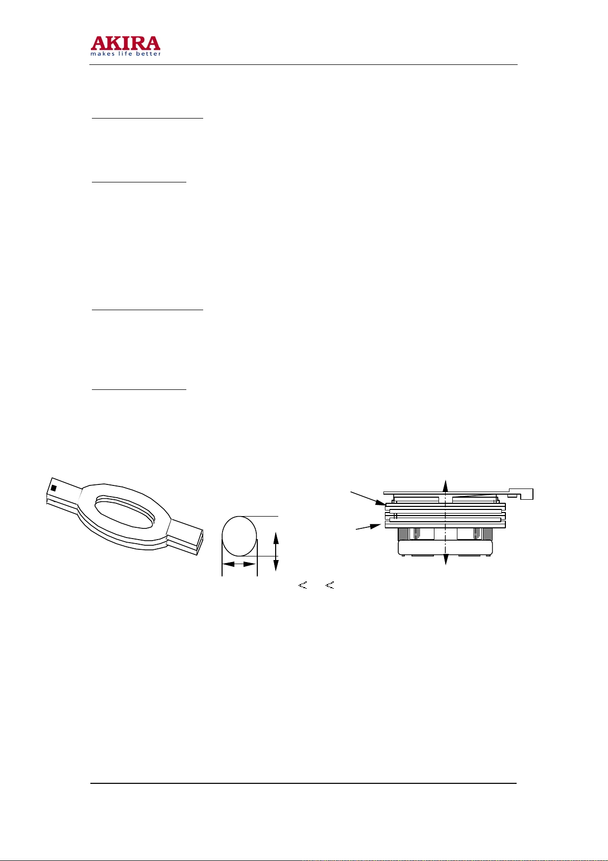
Adjustment of Beam Alignment
Preparation of Adjustment:
1 Turn on the TV set and age for more than 30 minutes.
2 The adjustment of raster inclination being finished, adjust the lens focusing roughly.
3 The contrast is set to maximum, and others to medium.
4 Receive the PAL video dot signal or the square signal.
Adjustment Procedure:
1 Cover the red and the blue projection tubes with lens covers to display the green raster only on the
screen.
2 Revolve the magnetic sheet of green projection tube for aligning the electric beam to the invalid
position as shown below.
3 Return the focusing potentiometer of the green projection tube on the focusing case
counterclockwise to the end, and confirm the central position of the defocused dot raster or the
square crossing dot raster on the screen as a standard position.
4 Turn the focusing potentiometer clockwise to maximum.
5 Revolve the two magnetic sheets for electric beam alignment to make the crossing center coincident
with the standard position confirmed in step (3).
6 Turn the focusing potentiometer counterclockwise to check if the center of the picture moves.
7 Repeat Steps 3 6 until the picture center does not move in step (6).
8 Adjust the electric beam alignment of the red tube and the blue tube with the same method as above.
4-pole
Projection tube screen side
2-pole
electron
b
a
Specification:
0.9 a/b 1.1
Projection tube electron gun side
Model No.: PTV-50H08
Version: 1.0
Page 14
Geometric Center of
-14 -
Adjust the Shape of Electron beam
Preparation of adjustment:
1. Press Key SK01 on the convergence plate once to exit the convergence mesh.
2. Output the video dot signal from the signal generator to AV3, and set the TV set in AV3 status, the
scanning mode to 60P.
3. Cover the lenses of the red and the blue projection tubes to allow the green light only to project to the
screen.
Red
Green
Blue
the Screen
L1
L2
Adjustment Procedure:
1. Turn the green static focusing potentiometer on the focusing case clockwise to maximum.
2. Adjust the 4-pole magnetic sheet of the green tube to make the circle round, as shown in the
following figure. Adjust mainly the screen center and meanwhile give attention to the whole screen
so as to make the beam shape of the whole screen best.
3. Adjust the electron beam shape of the red and the blue tubes with the same method as above.
4. After finishing the adjustment, turn the red, green and the blue static focusing potentiometers to
make the focusing optimum.
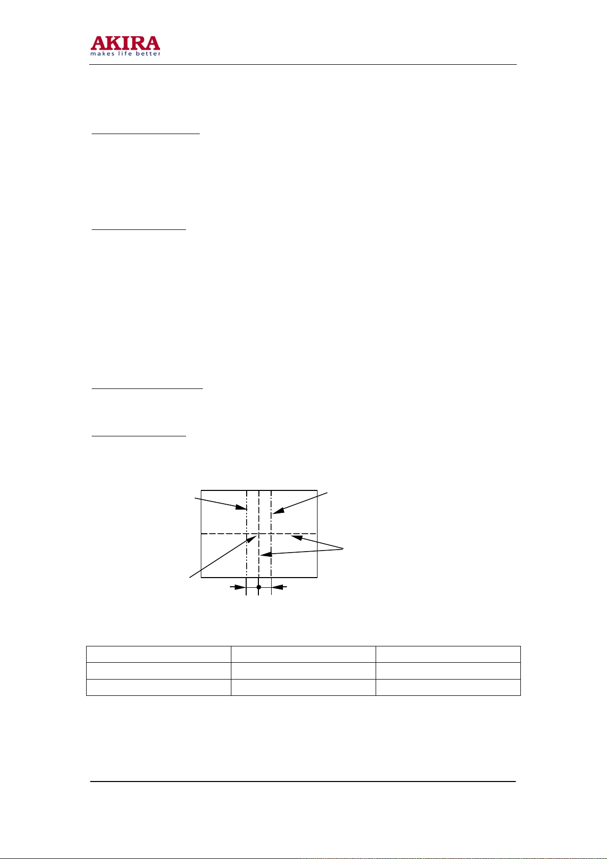
Fine adjustment of the Raster Position
Preparation of Adjustment:
Turn on the TV set with Key SK01 pressed to enter the under convergence status, the under convergence
mesh displayed on the screen.
Adjustment Procedure:
1. Revolve the center adjustment magnetic sheets of the red, the green and the blue tubes respectively
to move the centers of the squares as specified below:
2. Requirement in the horizontal direction:
Screen Size (feet) L1 L2
43 25mm 30mm
50 25mm 25mm
Red: L1 is the deviation distance of the screen center to the left, L1 2mm.
Blue: L2 is the deviation distance of the screen center to the right, L2 2mm.
Green: Coincident with the geometric center of the screen.
Model No.: PTV-50H08
Version: 1.0
Page 15
-15 -
3. Exit the status of under convergence.
Press the convergence key conv on the side panel to exit the convergence mesh.
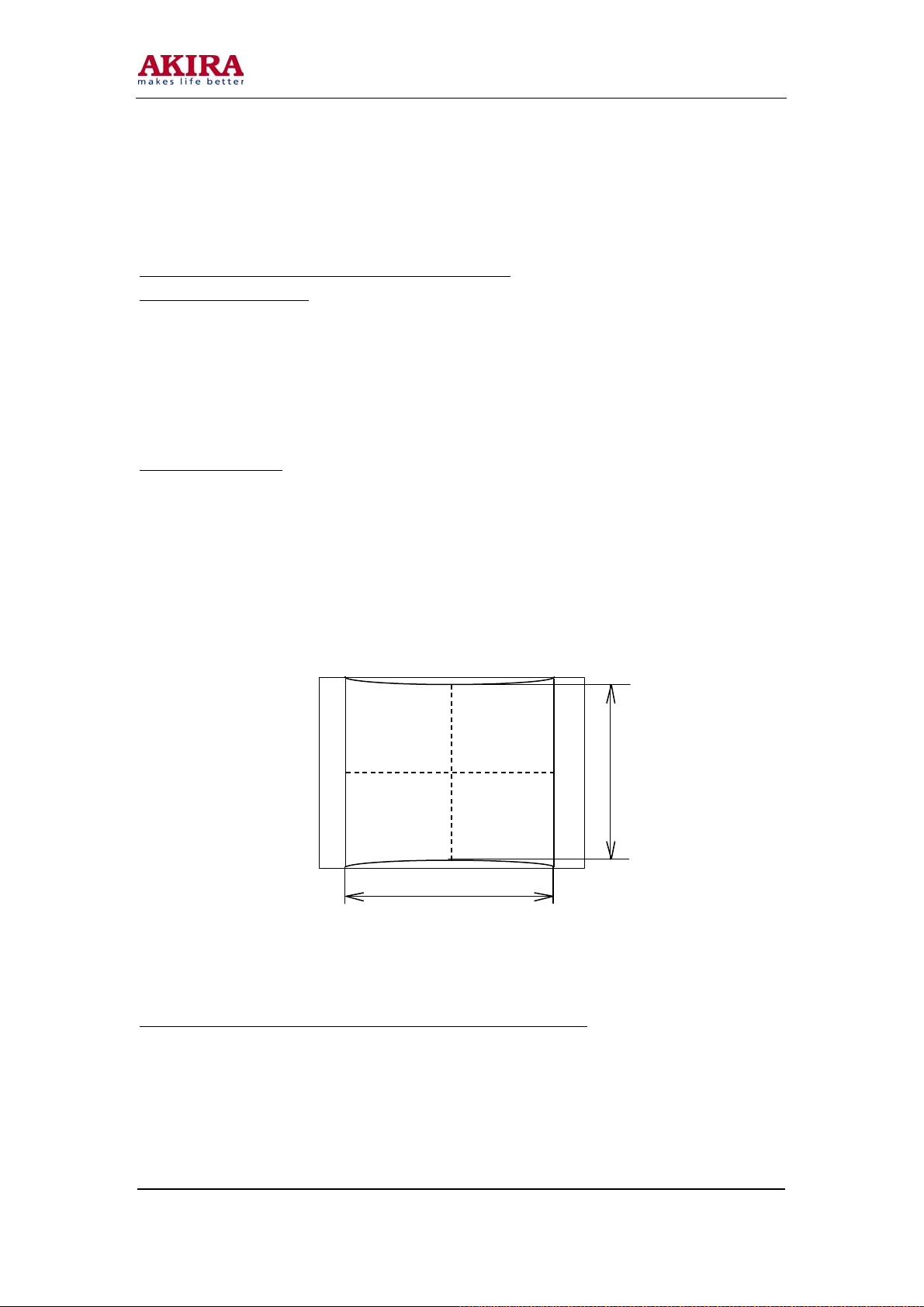
Adjustment of Geometric Linearity
Adjustment of Geometric Linearity for Scanning Mode 60P
Preparation of Adjustment:
1. Set the scanning mode to 60P.
2. Set the picture contrast to maximum, other controlling items to medium.
3. Press Key SK01 on the convergence plate together with Key MUTE on the remote controller and
confirm to display the green convergence mesh signal.
4. Press Key MENU on the front panel together with Keys MUTE and TXT on the remoter controller
in sequence to enter the “M” status.
Adjustment procedure:
Adjust the field breadth HIT, the row breadth WID, the pincushion DPC, the echelon KEY, the upper
corner UCNR and the lower corner so as to make the side lines of the convergence mesh straight and
parallel to each other, the distance between the centers of the upper and the lower edges of the
convergence mesh is: L1=550 5mm(43 ) / L1=640 5mm(50 ), and the distance between the centers of the
left and the right edges of the Geometric Center of the Screen Blue convergence mesh is: L2=850 ±5mm
(43” )/ L2=990 5mm(50” ).
Adjustment of Geometric Linearity for Scanning Modes 100I and 1250I
Receive PAL 100I and YPRPB 1250I signals. Adjust the geometric linearity of 100I and1250I with the
same method as that of the 60P.
L1
L2
Model No.: PTV-50H08
Version: 1.0
Page 16
-16 -
Optical Adjustment
Adjustment of the Electronic Focusing
Preparation of Adjustment:
1. Receive the PAL dot square signal with the scanning mode of 60P.
2. Set the contrast to maximum, and the brightness to medium.
Adjustment Procedure:
1. Adjust the red, the green and the blue lens separately (in any order). Cover the other two lenses while
adjusting one of the three to allow the light of single color to project to the screen.
2. Adjust the red, the green and the blue convergence potentiometer separately to get an optimum
convergence.
Adjustment of Lens Focusing
Preparation of Adjustment:
1. Receive the PAL dot square signal with the scanning mode of 60P.
2. Set the contrast to medium, and the brightness to minimum.
3. Loosen the bolt or the butterfly nut on the lens support to allow the lens support to turn (Note: do not
over loosen). The torque to screw the bolt or the butterfly screw is 1.18N·m (12kgf·cm) 1.67N·m
(17kgf·cm).
4. Adjust the red, the green and the blue lens separately (in any order). Cover the other two lenses while
adjusting one of the three to allow the light of single color to project to the screen.
5. Observe the screen. When turning the knob clockwise, the color distortion will change as follows:
Lens
Red Orange Dark red
Green Blue Red
Blue Purple Green
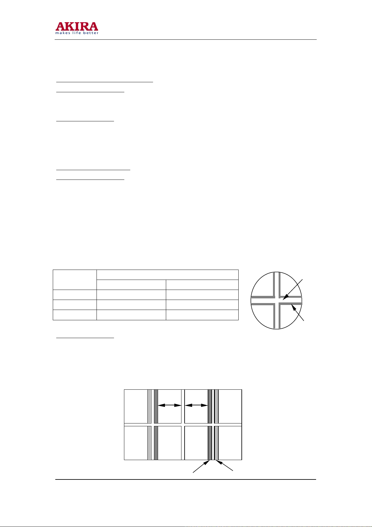
Adjustment Procedure:
1. Adjust the focusing of the green lens.
While adjusting the position of the color distortion from blue to red, if the color distortion of the
whole screen is different, observe and adjust the focusing of the straight bright line according to the
specifications in the following figure and table. If the red distortions of the straight lines at both sides
are different, observe and adjust the side with larger distortion.
Model No.: PTV-50H08
Version: 1.0
Change of Color Distortion Lens
Short Focus Long Focus
Mesh
Aberrant color
L1
L2
I O
Page 17
-17 -
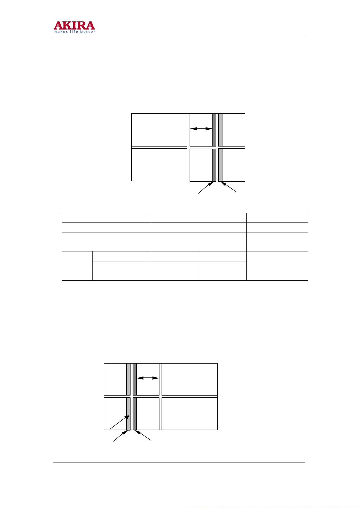
2. Focusing of the red Lens
While adjusting the position of the color distortion from orange to dark red, observe and adjust the
focusing of the straight bright line according to the following figure. The inner and the exterior
distortion of orange or dark red tally with the specifications in the following table: (reference
value:1~ 3mm)
Lens Specification Unit
Screen size 43 50 Feet
Square
Color
distortion
Note: * slight orange or colorless
** slight dark red or colorless
3. Focusing of the Blue Lens
While adjusting the position of the color distortion from purple to green, observe and adjust the
focusing of the straight bright line according to the following figure. The inner and the exterior
distortion of purple or green tally with the specifications in the following table: (reference value:1~
O
3mm)
At the edge * *
I (inner side) * (max 2mm) * (max 2mm)
O (external side) ** (max 2mm) ** (max 2mm)
L
I O
5.0 3.0 Square of the mesh
Note
L
I
Model No.: PTV-50H08
Version: 1.0
Page 18
-18 -
Lens Specification Unit
Screen size 43 50 Feet
Square
Color
distortion
Note: * slight purple or colorless
** slight green or colorless
At the edge * *
I (inner side) * (max 2mm) * (max 2mm)
O (exterior side) ** (max 2mm) ** (max 2mm)
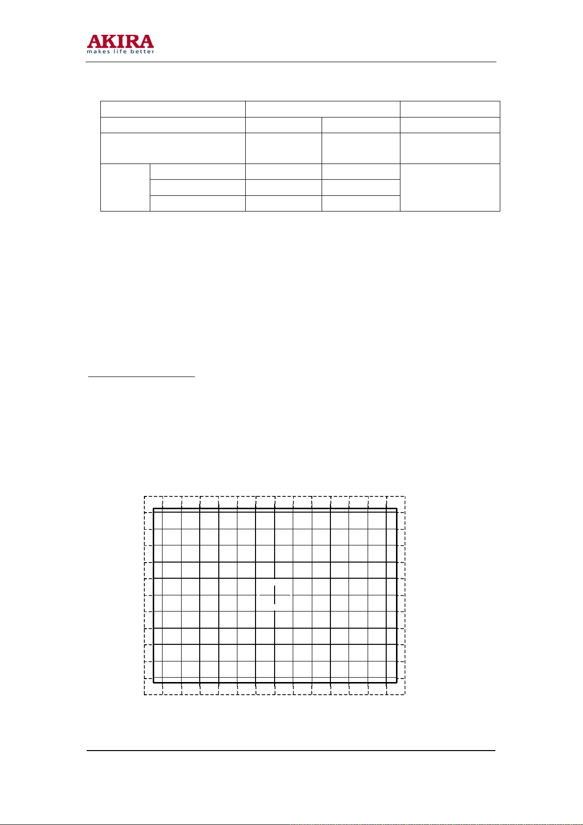
Overall Check of Focusing
Receive the signals of the digital card and confirm the normality of the overall focusing.
Manual Adjustment of digital convergence.
Preparation of Adjustment:
1. Receive the PH graphic card signal of the PAL system, and make the following adjustment in the
scanning modes of 60P, 100I and 1250I YPRPB signal respectively.
2. Press Key SK01 on the convergence plate and confirm to enter the status of digital convergence. (In
addition, press Key CONV on the side panel together with Key TV/AV on the remote controller to
enter the status of digital convergence.)
3. 208 adjustment dots 16×13 in total. Change the dot (cursor) position with Keys 2, 4, 5, 6 and 8 on the
remote controller.
5.0 3.0 Square of the mesh
Note
Model No.: PTV-50H08
Version: 1.0
Page 19
-19 -
Adjustment Procedure:
1. Select the mesh to be adjusted with key picture on the remote controller, and select the mesh to be
displayed with key sound on the remote controller.
2. Adjust the deviations of blue and red based on green to make it less than 1mm.
3. Write: Press Key Write on the remote controller and confirm the write with Key Sound (press Key
Mix to cancel the write). Return to the adjustment status after the write. Readjust if the convergence
deviation exceeds 1mm.
4. Press Key SK01 on the convergence plate, Key CONV on the front panel or Key Exit on the remote
controller to exit the convergence status.
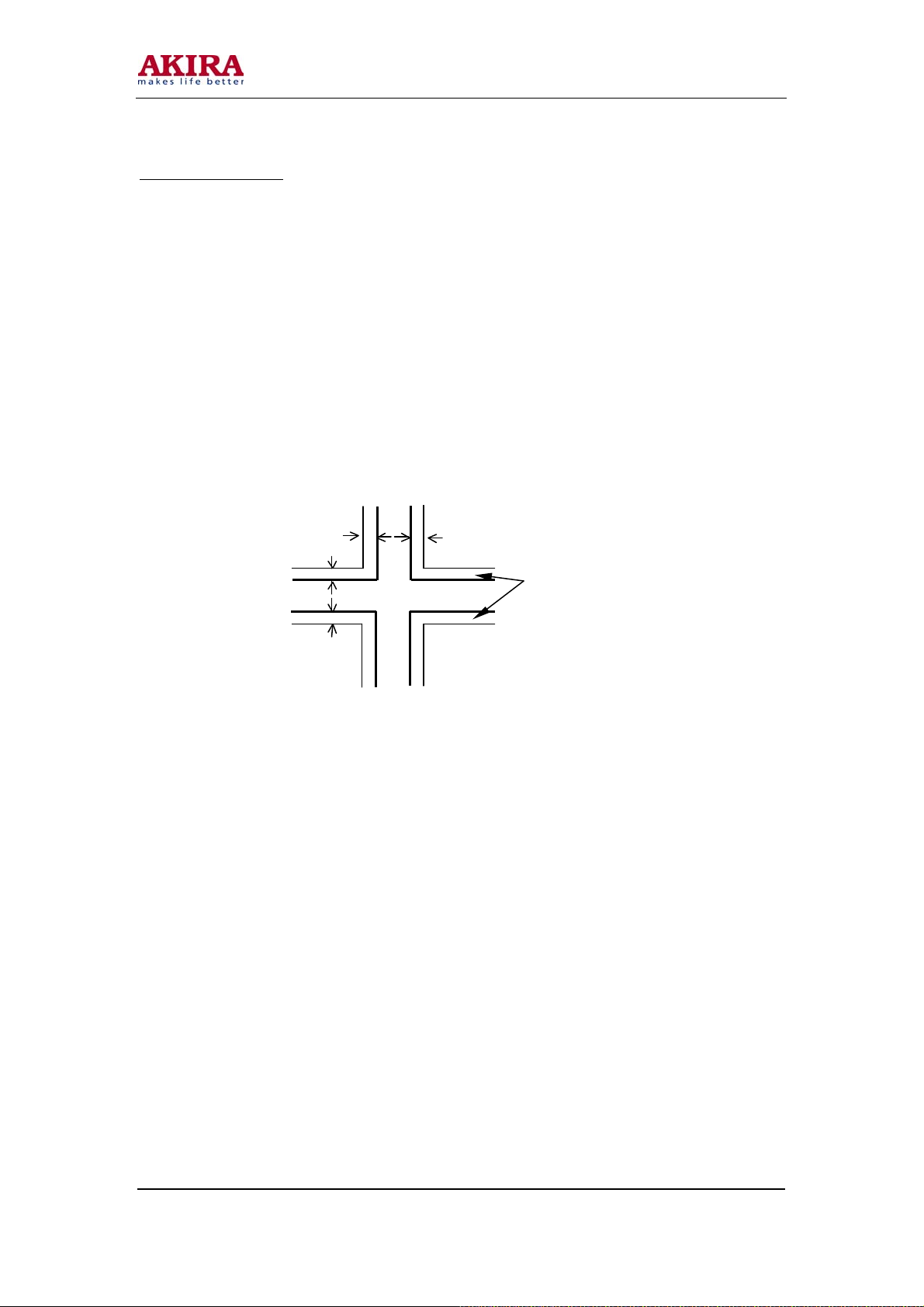
5. Adjustment on Blue Defocusing
a. Receive the PAL dot square signal.
b. Turn the blue focusing potentiometer clockwise to maximum.
c. Turn the blue focusing potentiometer counterclockwise to protrude the blue focusing
Nine-dot Convergence Adjustment for Users: adjust with three scanning modes of
60P, 100I and 1250I YPRPB signal respectively.
1 Enter Nine-dot Convergence Adjustment for Users:
In the TV mode, press Key CONV on the side panel to enter the adjustment status, and the nine dots
distributed on the screen.
2 Exit Nine-dot Convergence Adjustment for Users:
i. Wait for 60 seconds with no adjustment to automatically exit the adjustment status.
ii. At the nine-dot convergence status, press Key ESC on the remote controller to exit
iii. Press Key CONV on the side panel to exit with data saved.
3 Position Selecting in Nine-dot Convergence Adjustment for Users:
Press Keys 1 to 9 on the remote controller to move the cursor onto the position to be adjusted.
4 Color Selecting in Nine-dot Convergence Adjustment for Users:
Press Key i on the remote controller to alter the color.
5 Data Resetting in Nine-dot Convergence Adjustment for Users:
Method one: In the status of Nine-dot Convergence Adjustment for Users, press Key Reset on the
remote controller.
Method two: Power up the TV set with Key CONV on the side panel being pressed.
in the screen center a distance of less than 1 mm, as shown in the following figure.
Blue protrusion
without saving data; press Key CONV on the side panel to exit with data saved.
Model No.: PTV-50H08
Version: 1.0
Page 20

-20 -
Adjustment of High Voltage
Adjustment Procedure
1. Power off the TV set, pull the high voltage cable of the blue tube out of the high voltage distribution
box and put it aside, with its pin away from the TV set core.
2. Connect the ground wire of the high voltage meter to the ground of the green tube, and insert the
probe into the high voltage distribution box with a good touch.
3. Power up the TV set, and regulate the high voltage potentiometer RH17 to get a voltage of 30.2 ±
0.2kV indicated on the high voltage meter.
4. Power off and remove the probe and the ground wire of the high voltage meter.
5. Insert the high voltage cable of the blue tube back into the high voltage distribution box and make
sure to be well inserted and sealed.
6. Drop 0.1gram of silica gel 708 onto RH17. Try not to change the value of the potentiometer.
7. Power up and switch on the TV set and check if there is any abnormity.
Model No.: PTV-50H08
Version: 1.0
Page 21

-21 -
NOTICE FOR MAINTENANCE
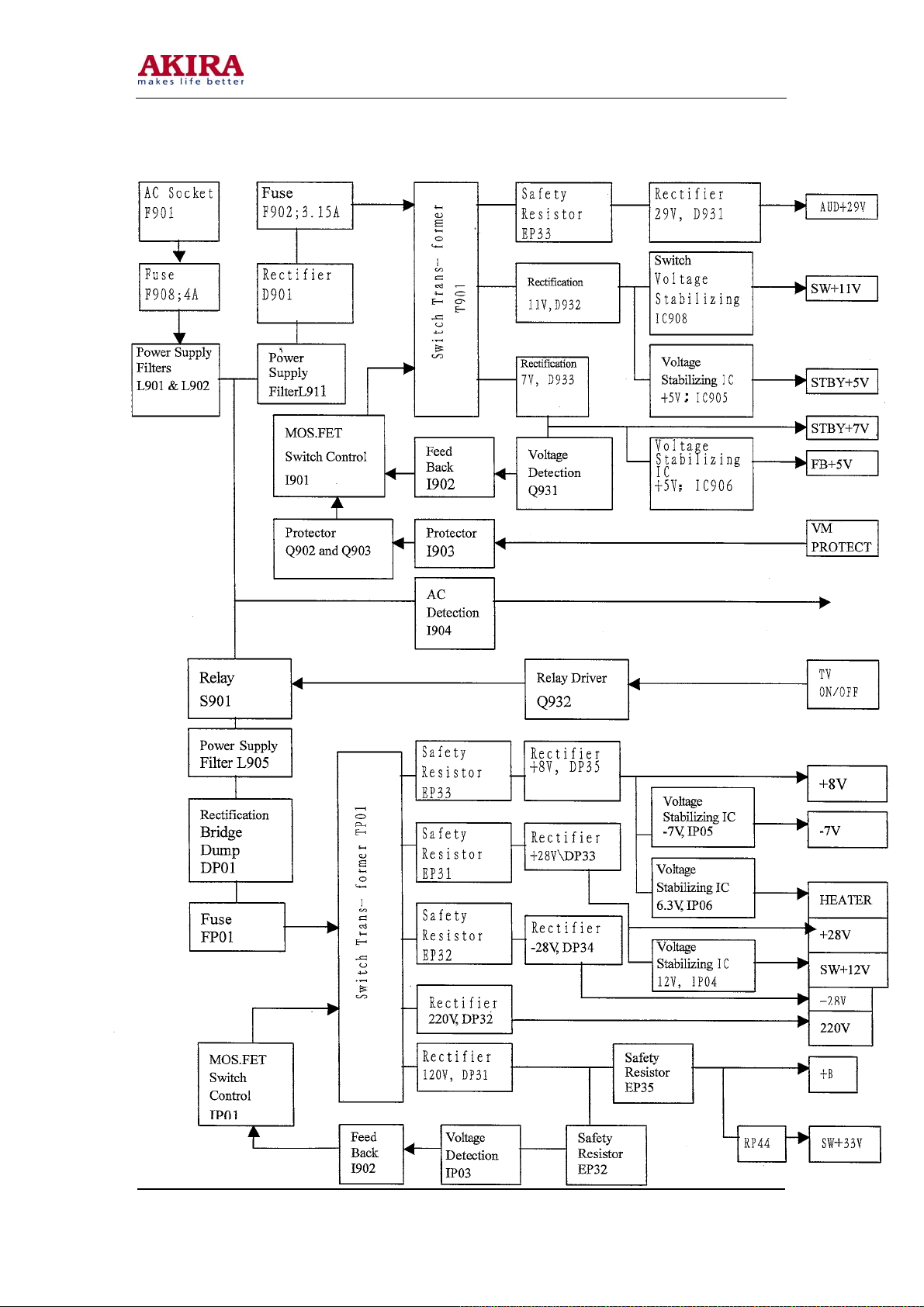
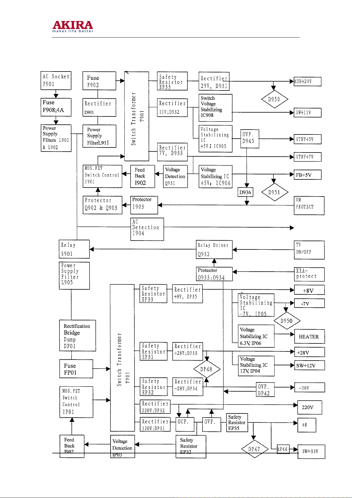
Circuit Description
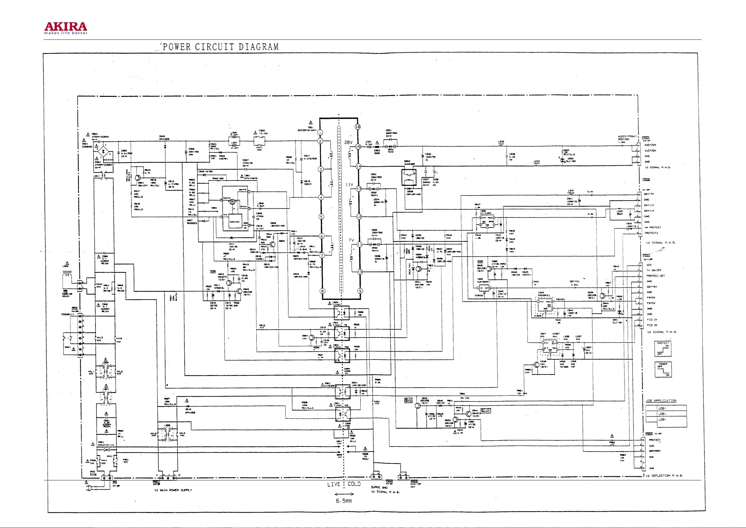
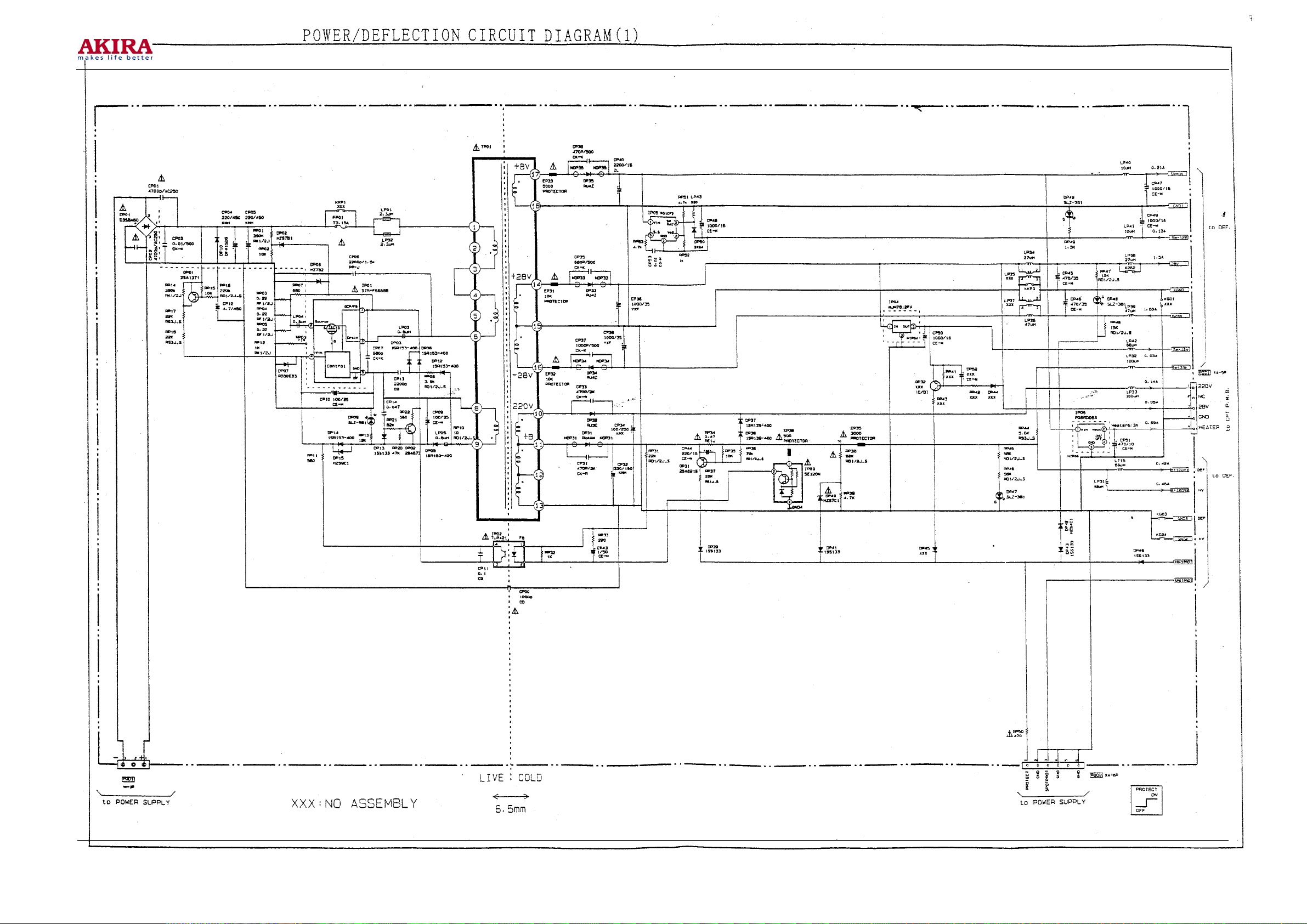
1 Description of the Power Supply Diagram
The TV set core has two set s of power supply.
Normally the power supply is as follows:
T901: 45KHz (Typical), 20KHz (Stand-by)
TP01: 30-60kHz (Typical)
2 Secondary Power Supply:
To supply power for STAND BY, signal circuits and the audio amplifier.
Power supply is also available in STAND BY mode whenever AC power is connected. Meanwhile,
the power is supplied to the signal circuit and the audio amplifier circuit.
The following voltages are generated on the secondary power supply chassis:
STBY+5V (Stand by +5V) : supply power for E2PRAM, OSD_R/G/B and CPU with a voltage
stabilizer N802/N803 (output +2V5 and +3V3)
STBY+7V Supply +5VA through IP71 to N812 (PI5V330), the decoding board and IY01
(HD74HC221FP).
SW+11V Get SW+9V-1 (on the diagram: +9V) through IP73: ON/OFF of the fine sound board and
IP71 and the VIDEO/MONO output of the tuner.
Get SW+9V-2 through IP74: TA1316AN/19pin_45pin_55pin, RGB output
/QC31_30_36_35_41_40, VM output/QC26, convergence signal input /QC22_23_24, the video
playing board, TA1317AN and Q707_708 (protection).
.FB+5V: decoding board.
.+29V: supply for the audio amplifier circuit.
3 Primary Power Supply:
Supply power for the circuits of deflexion, high voltage generating, convergence, video output and
VM. This power supply will work only when the complete TV set is switched on. When receiving
the switching on signal from the microprocessor, Relay S901 is closed, and the AC power passes
through the zener diode DP01 to the circuits of deflexion, high voltage generating, convergence,
video output and VM.
Model No.: PTV-50H08
Version: 1.0
Page 22
-22 -
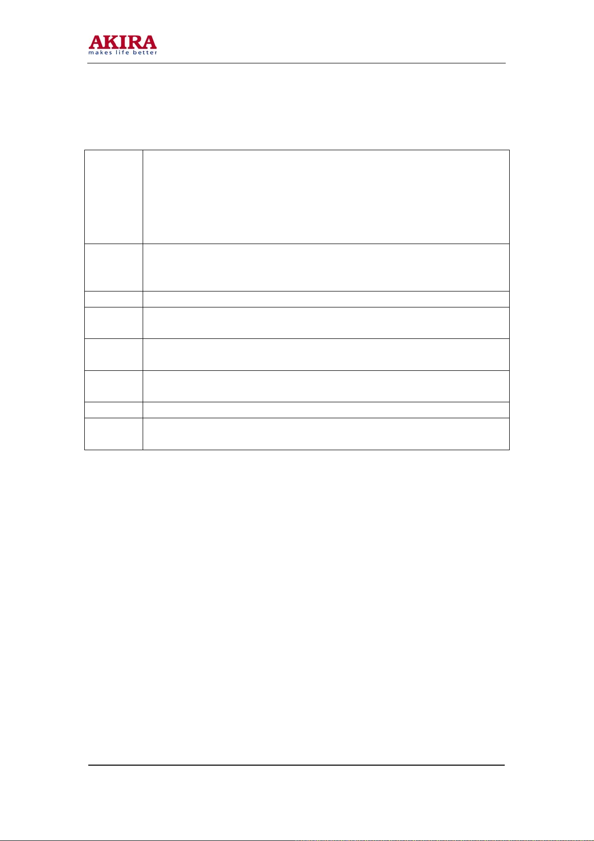
Generating the following voltages:
B+120V Being separated into two circuits. One passes through L715 to the line deflexion circuit,
i.e. B+120V1 in the schematic diagram of the electric deflexion plate to supply power
for the line deflexion output circuit Q777. The other one passes through L731 to the high
voltage regulation circuit, i.e. B+120V2 in the schematic diagram of the electric
deflexion plate to supply power for the high voltage regulating tube QH01 and the high
voltage assembly TH01.
+28V To the field output circuit I601(LA7846N); to Q709 via R74B\R730; to the convergence
plate via Jumpers 5 and 6 of PDKP; and to the convergence plate via Jumpers 11 and 12 of
T701 generating -28VP-P .
SW-12V To the convergence plate via Jumper 4 of PDK3.
+12V To the high voltage generating circuit IH01; the pincushion correction circuit Q657; to the
convergence plate via Jumper 1 of PDK4.
+28V and
-28V
SW+8V To the convergence plate via Jumper 3 of PDK3 generating -7V for the digital
+220V be provided to the video output circuit
+220V and
+28V
There are some voltage stabilizers equipped on the signal chassis, which are the one for stabilizing
SW+11V into two +9Vs and one 5V, the one for stabilizing STBY 7V into 5V and the one for stabilizing
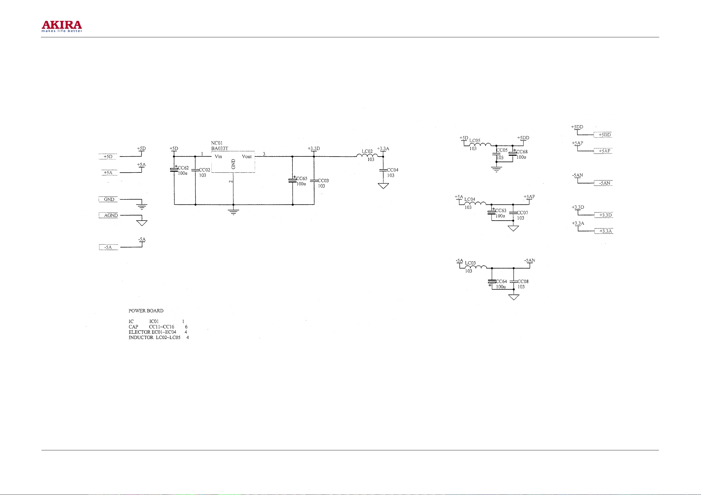
STANDBY+5V into +3.3V and +2.5V to supply power to CPU.
Meanwhile there are two voltage stabilizers on the convergence plate, which are the one for stabilizing
SW+8V to +5V and the one for stabilizing SW-7V to -5V.
Model No.: PTV-50H08
Version: 1.0
be provided to the convergence output circuit
convergence unit; to Q754 and IP06 generating 6.3V for filaments of projection tubes.
be provided to the VM circuit
Page 23
-23 -
Power Supply Diagram
Model No.: PTV-50H08
Version: 1.0
Page 24
-24 -
Diagram of the Protection Circuit
Model No.: PTV-50H08
Version: 1.0
Page 25
-25 -
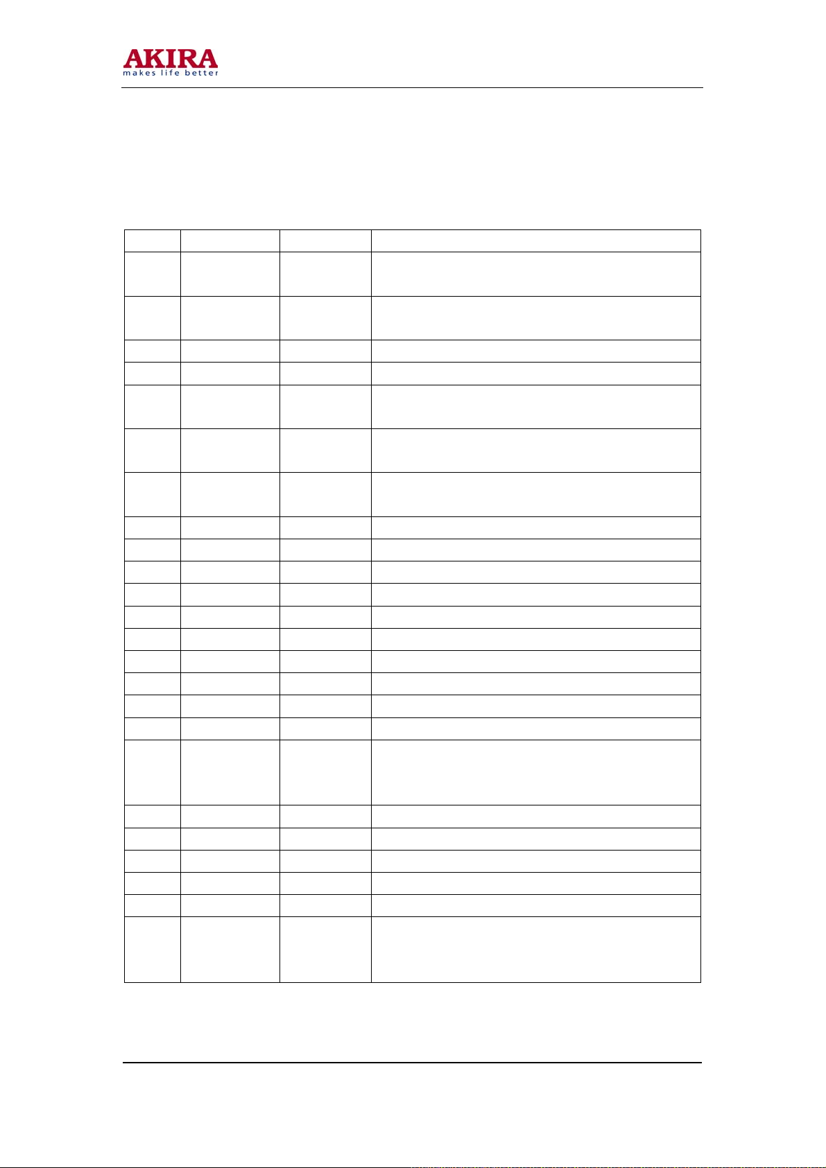
N801 Jumper Description
Table1 SDA555XFL Jumper Description
Jumper Function Type Specification
1/P0.0 SDA_1 IN/OUT SDA_1Bus, for control of tuner, sound effect board, AV
board, etc.
2/P0.1 SCL_1 IN/OUT SCL_1 Bus, for control of tuner, sound effect board, AV
board, etc.
3P0.2 SDA_E2PROM IN/OUT SDA_ E2PROM,
4/P0.3 SCL_E2PROM IN/OUT SDA_E2PROM, dedicated bus for E2PROM
5/P0.4 SDA_0 IN/OUT SDA_0 Bus, for control of DPTV board, TA1316AN board,
TA1317N board, etc.
6/P0.5 SCL_0 IN/OUT SDA_0 Bus, for control of DPTV board, TA1316AN board,
TA1317N board, etc.
7/P0.6 F_SW Input Low level available, for automatic adjustment and test of
white balance.
8/P0.7 IN/OUT NC
9 VDD2.5 Power Supply Voltage of the power supply
10 VSS Power Supply Ground
11 VDD3.3 Power Supply Voltage of input and output ports
12 CVBS_IN Input Input of color composite television signal
13 VDDA2.5 Power Supply Voltage of the power supply
14 VSS Power Supply Ground
15/P2.0 Input NC
16/P2.1 AFC_M IN/OUT Automatic frequency control of the main channel
17/P2.2 AFC_P IN/OUT NC
18 KEY_IN Input Local keys for A/D input. Key center voltages: 0.9V
program +, 1.5V program -, 2.1V volume +, 2.8V volume -,
3.5V TV/AV, 4.1V MENU. No key -- 5V
19 HS/SSC Input Input of line synchronization/ sand fort pulse
20 VS Input Input of vertical synchronization
21/P3.0 Input NC
22/P3.2 LED_POWER Output LED Level output, low level upon switching on.
23/P3.3 REMOTE_IN Input REMOTE input of remote controlling pulse
24/P3.3 INTER/PRO IN/OUT INTER-PRO level output, temporarily for field frequency
switching. Output low level at 100/120HZ; high level at
50/60HZ.
Model No.: PTV-50H08
Version: 1.0
Page 26
-26 -
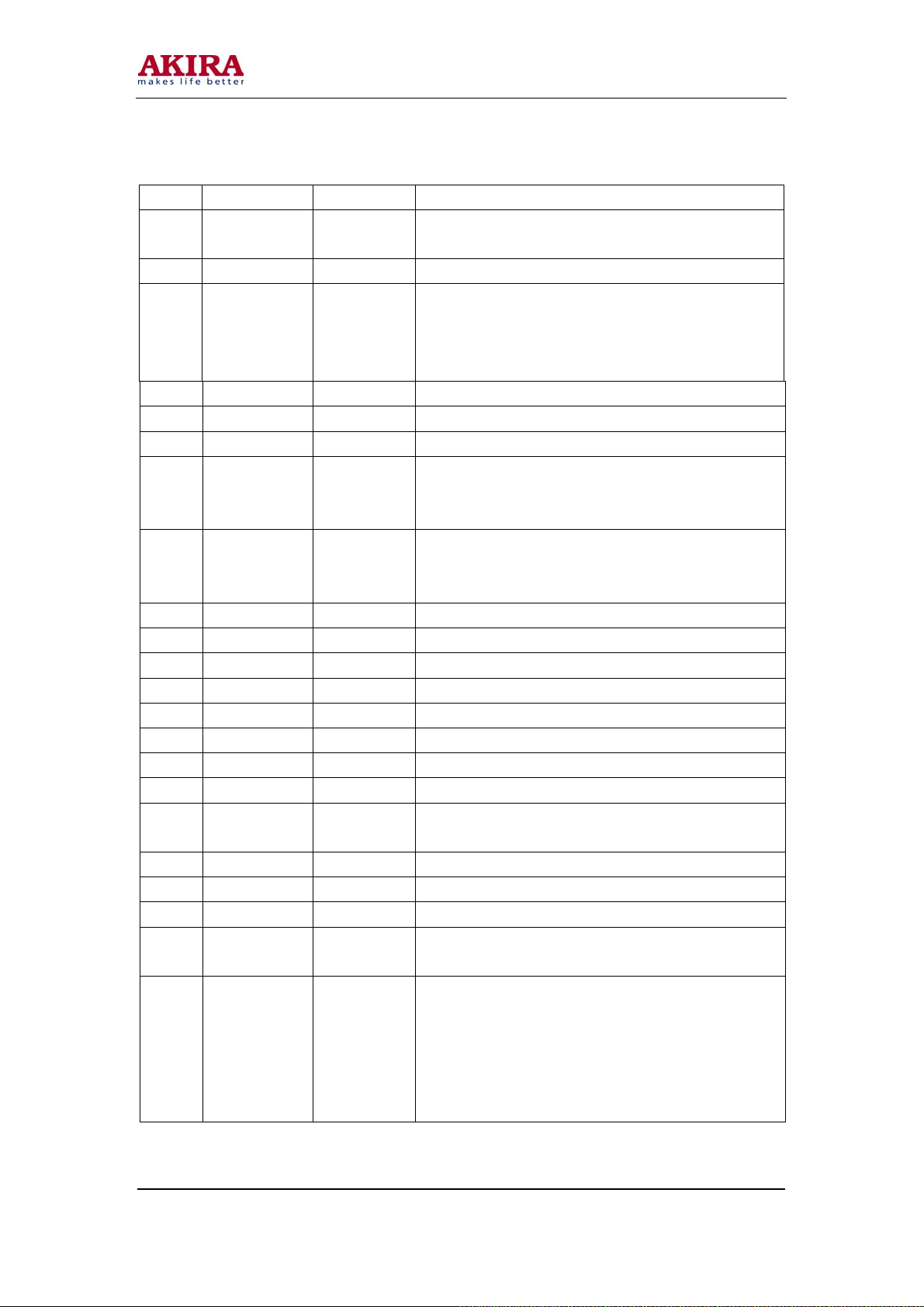
Jumper Function Type Specification
25/P3.4 SYNC_DET IN/OUT Synchronization detection, pulse input, separation of
synchronization from the AV board.
26/P3.5 IN/OUT NC
27/P3.6 PROTECT_DET IN/OUT Level input. High level input (via switching) when entering
the protection status due to abnormal power supply or
line/field board. CPU purges all settings and enter the
stand-by status.
28/P3.7 VGA_SW IN/OUT VGA switch
29 VSS Power Supply Ground
30 VDD3.3 Power Supply Voltage of input and output ports
31/P4.2 V_MUTE IN/OUT V_MUTE level output. Output the high level in such cases
that need image blanking as channel changing, switching
off, etc.
32/P4.3 A_MUTE IN/OUT AMUTE level output. Output the high level in such cases
that need sound muting as channel changing, muting,
switching off, etc.
33 RESET Input Enter the reset status: high level in order and low level reset.
34 XIN Input Clock input
35 XOUT Output Clock output
36 VSSA Power Supply Ground
37 VDD2.5 Power Supply Voltage of the power supply
38 OSD-R Output OSD-R OSD red displaying signal
39 OSD-G Output OSD-G OSD green displaying signal
40 OSD-B Output OSD-B OSD blue displaying signal
41 BLANK/COR Output Controlling signals for character blanking and translucent
display.
42 VDD2.5 Power Supply Voltage of the power supply
43 VSS Power Supply Ground
44 VDD3.3 Power Supply Voltage of input and output ports
45/P1.0 PAL/NT IN/OUT PAL/NT PWM , analog voltage output, two levels output,
represent two scanning modes.
46/P1.1 IN/OUT Input level. When the digital convergence module outputs
the high level, the convergence mesh is displayed on the
screen, with no convergence current output. Press a key to
enter the factory menu of the TV CPU (to adjust the
line/field amplitude and the geometric distortion). Low
level available.
Model No.: PTV-50H08
Version: 1.0
Page 27
-27 -
Jumper Function Type Specification
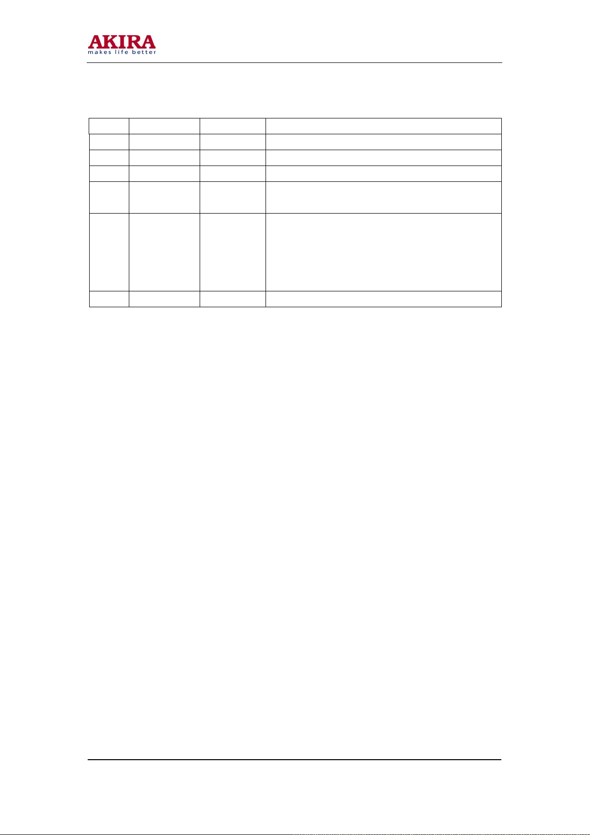
47/P1.2 IN/OUT Level output. RESET digital processing DPTV board.
48/P1.3 IN/OUT TV_ON/OFF TV on/off. Low level: on; high level: standby.
49/P1.4 Input NC
50/P1.5 BTSC_RST Input BTSC_RST level output. RESET fine sound chip
MSP3410G.
51/P1.6 BUSY Input BUSY convergence module detecting the level input. When
the convergence module outputting a high level, the
convergence mesh is displayed on the screen to enter the
convergence adjustment status, with the main CPU ignoring
the input from the remote controller.
52/P1.7 IN/OUT NC
Model No.: PTV-50H08
Version: 1.0
Page 28
-28 -
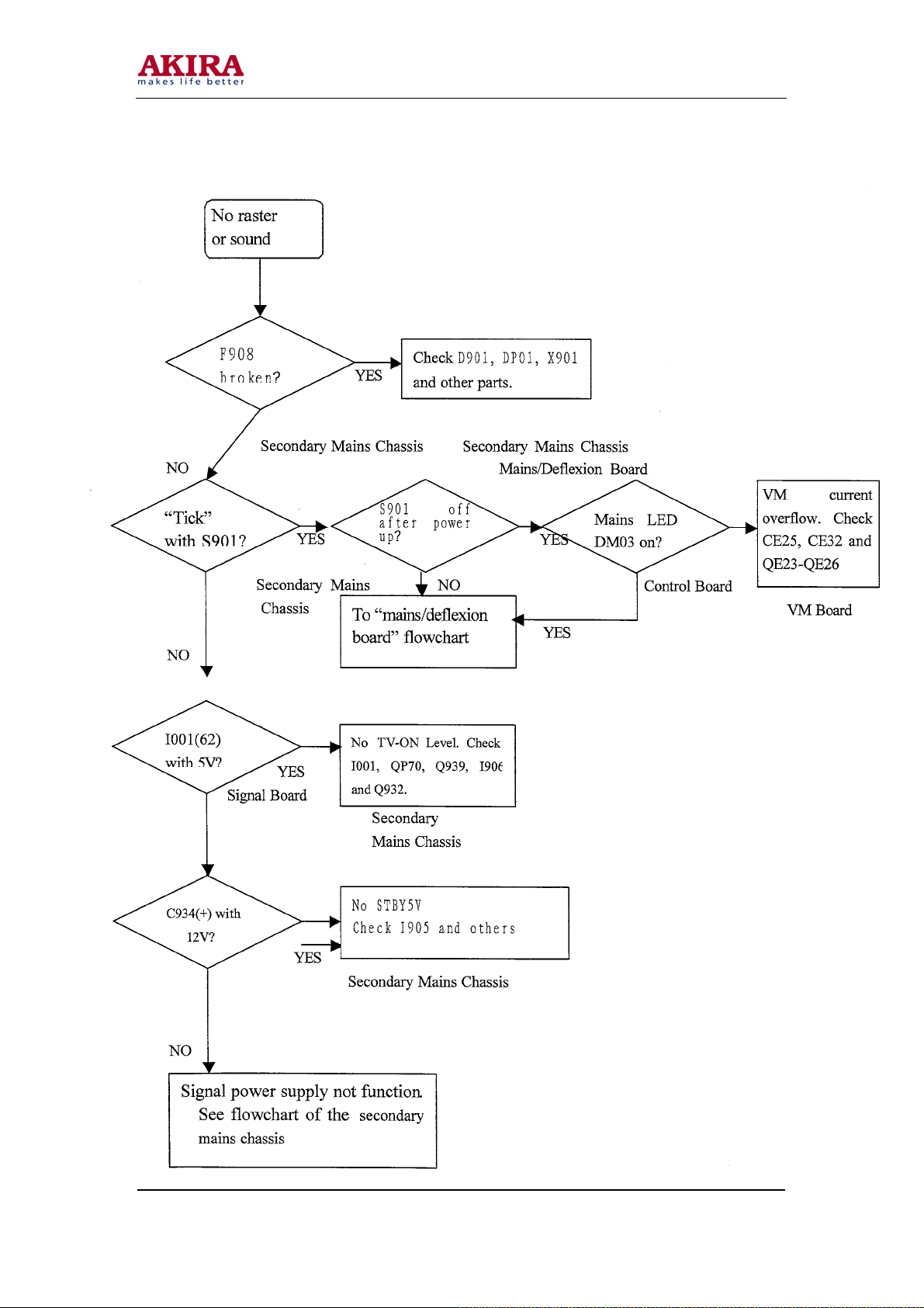
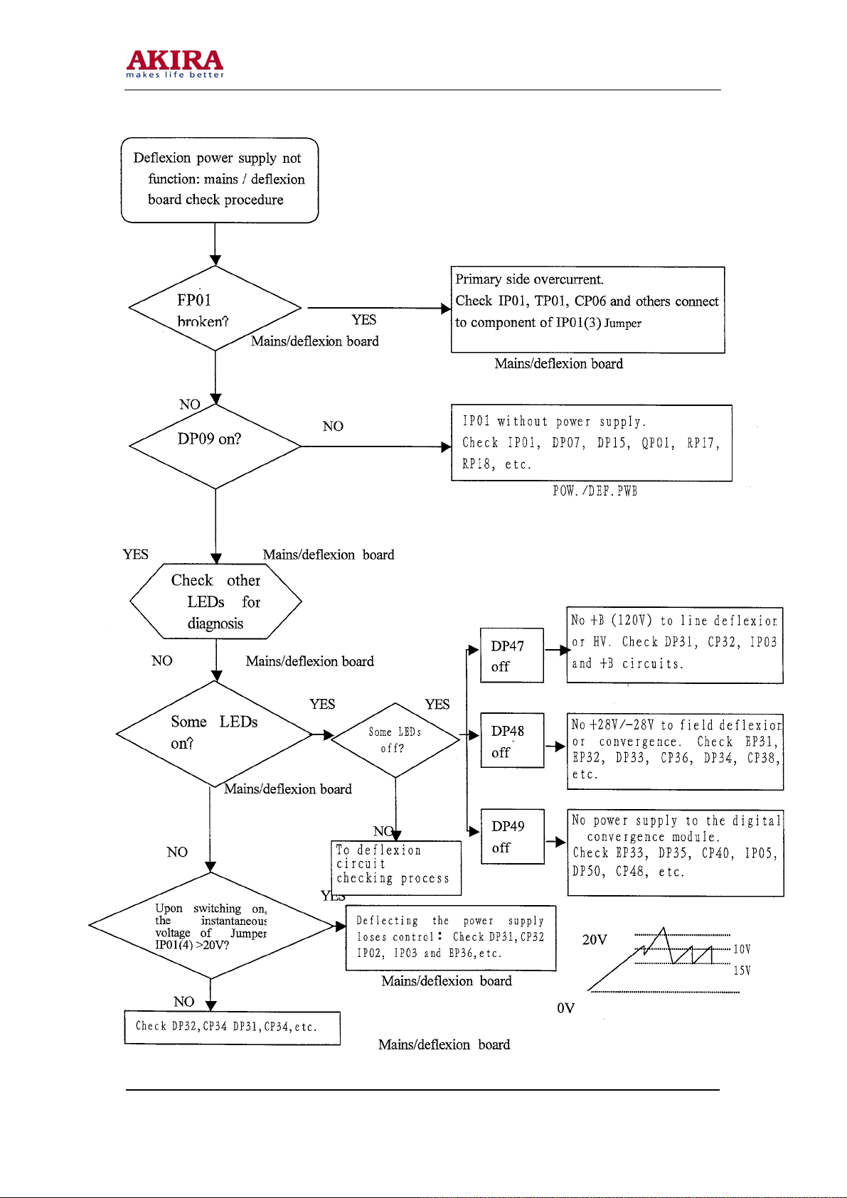
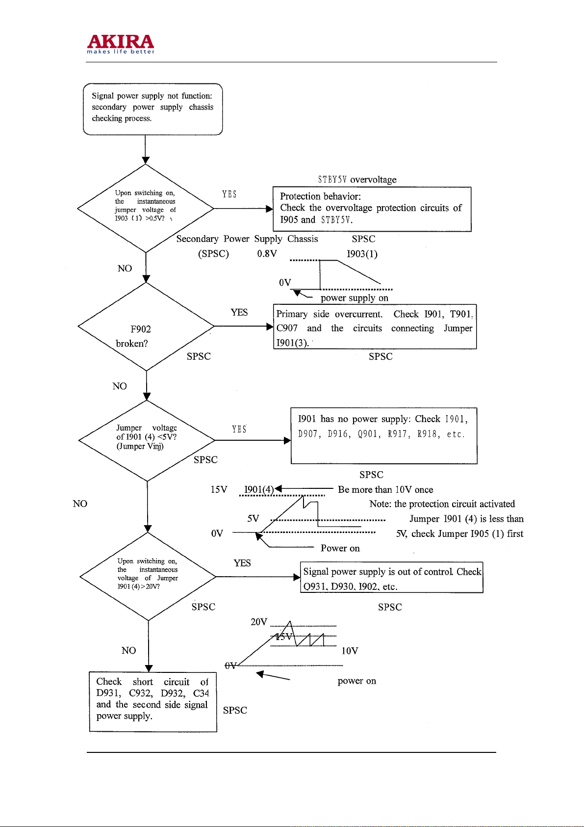
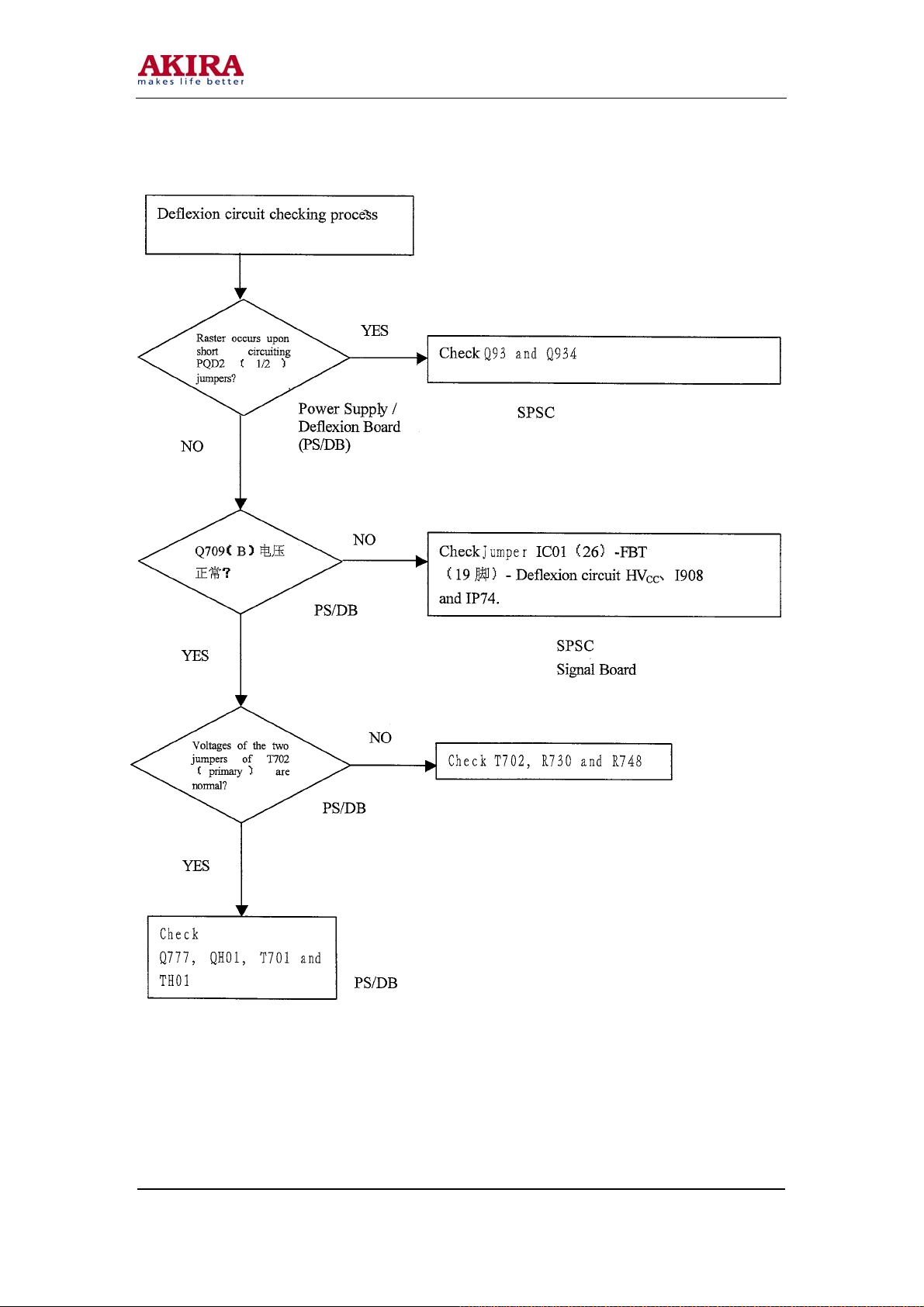
Flowchart of Maintenance Troubles
Model No.: PTV-50H08
Version: 1.0
Page 29
-29 -
Model No.: PTV-50H08
Version: 1.0
Page 30
-30 -
Model No.: PTV-50H08
Version: 1.0
Page 31
-31 -
Model No.: PTV-50H08
Version: 1.0
Page 32
-32 -
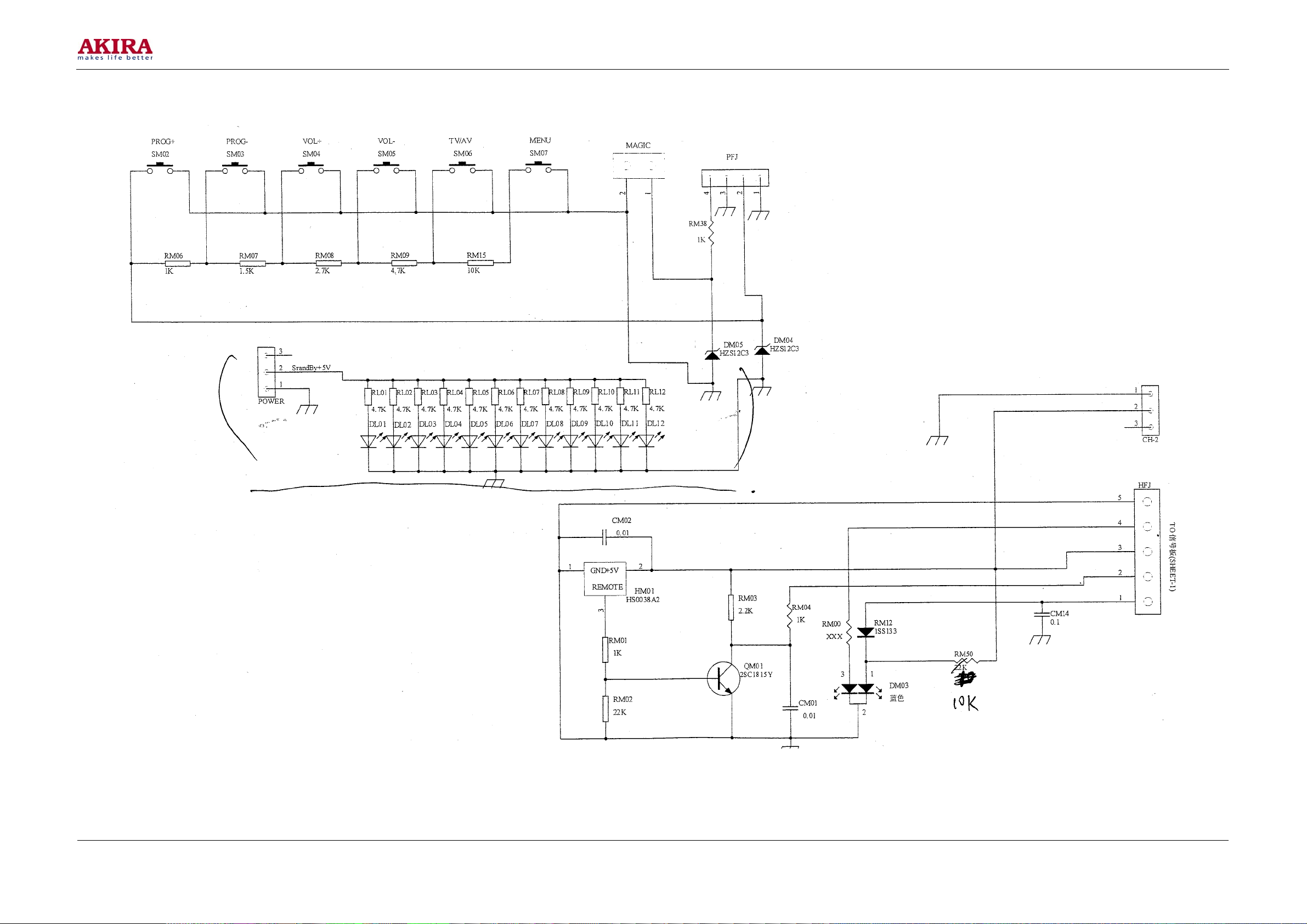
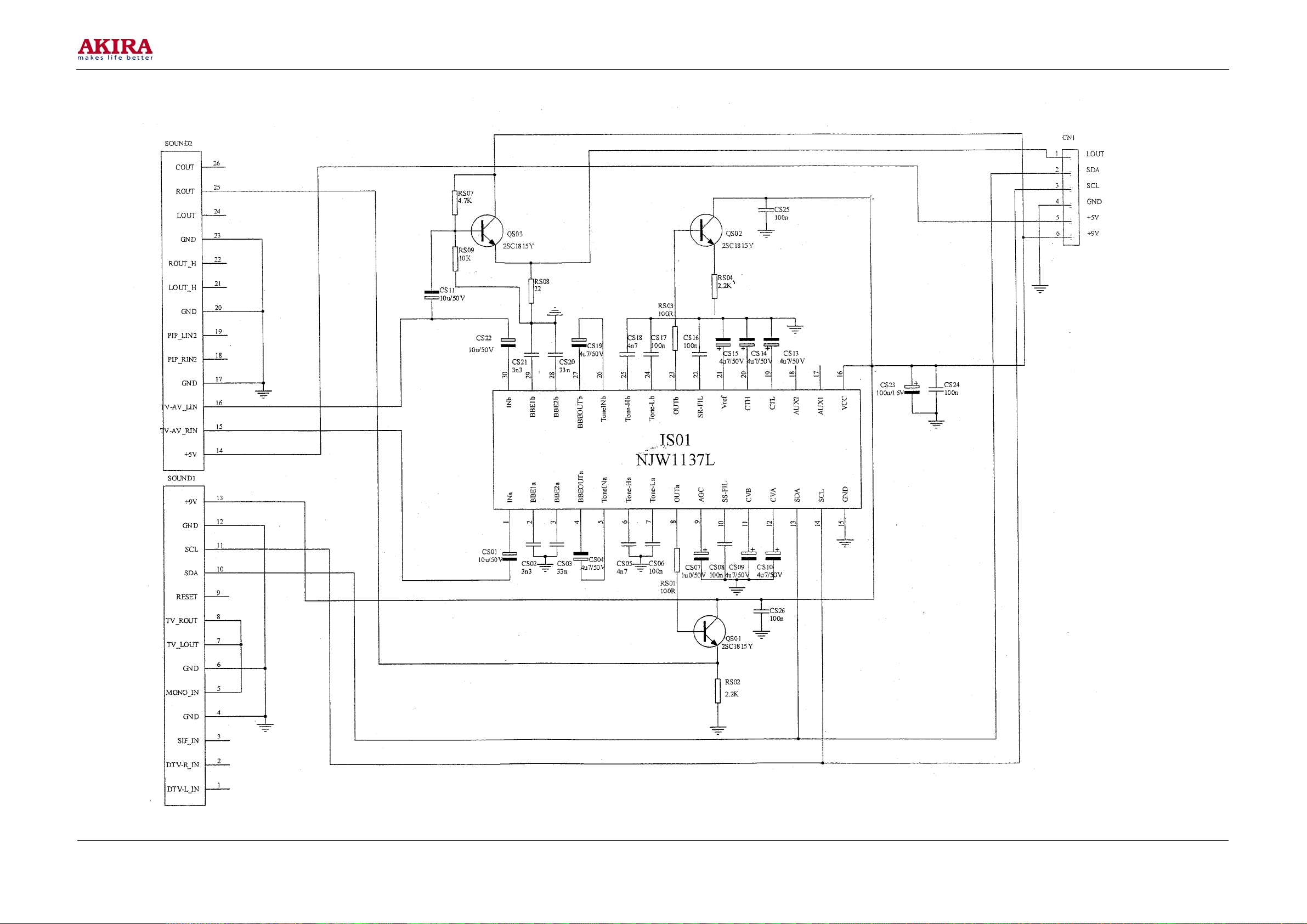
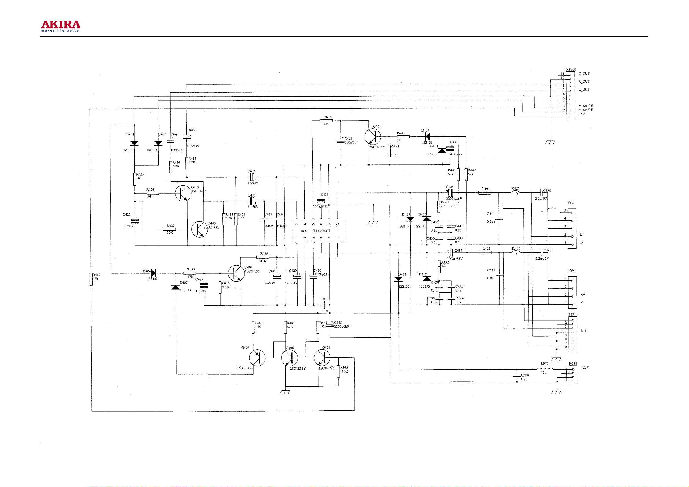
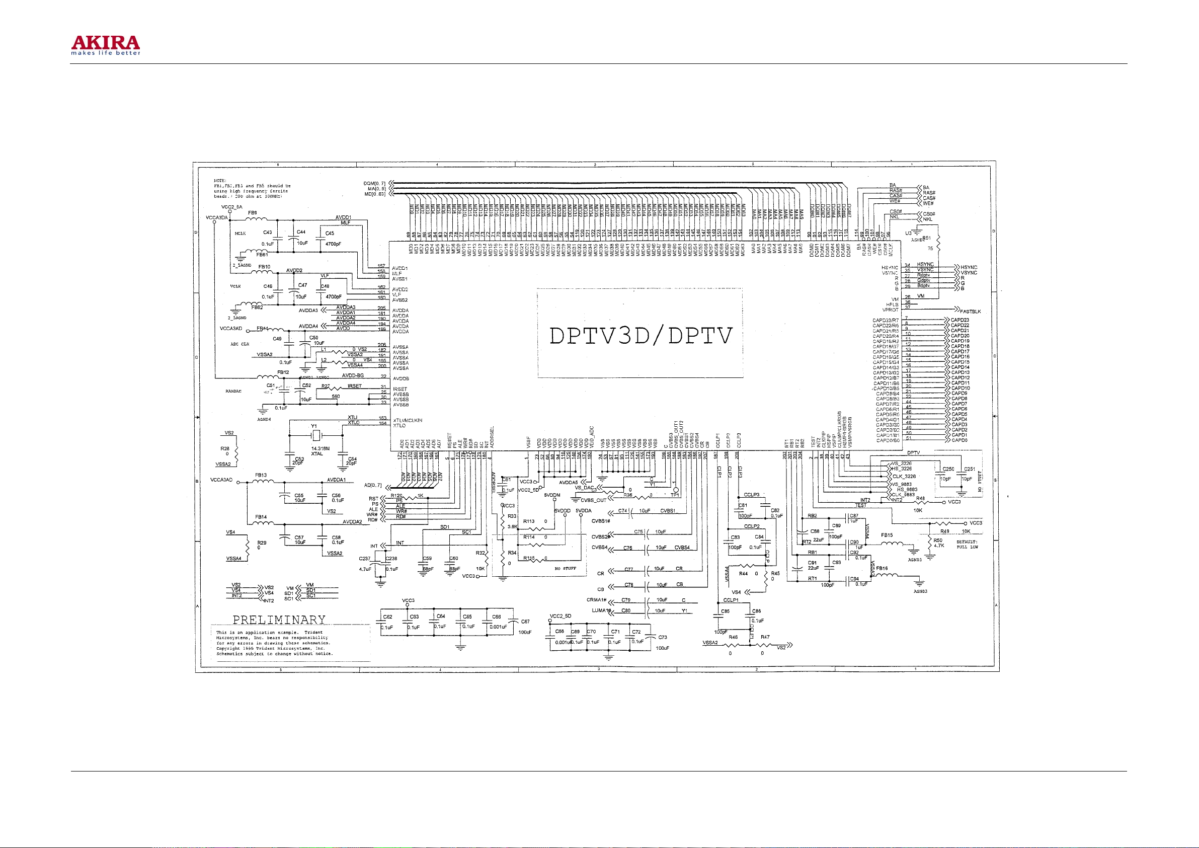
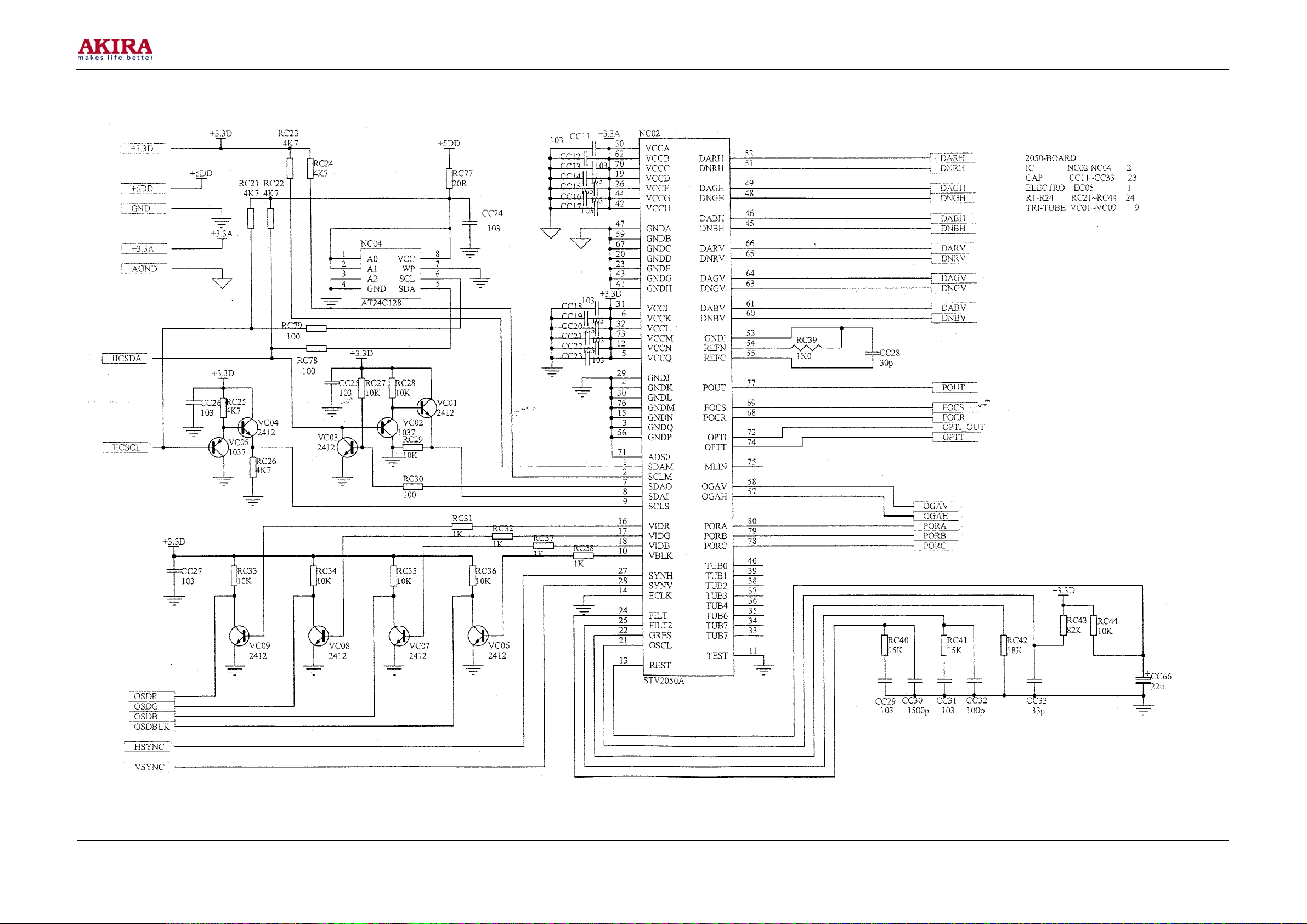
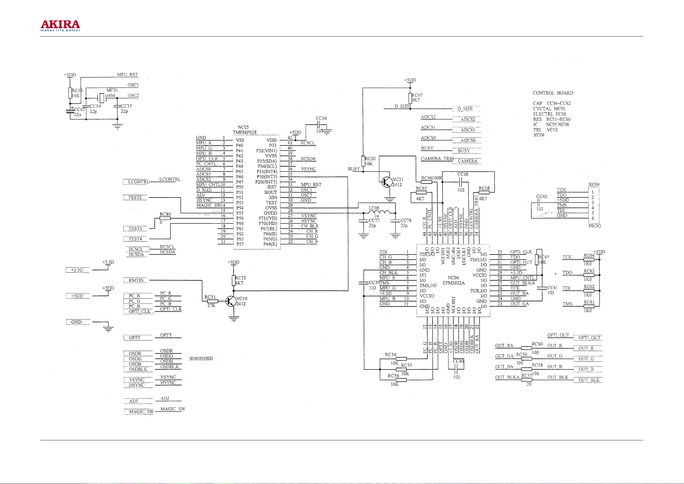
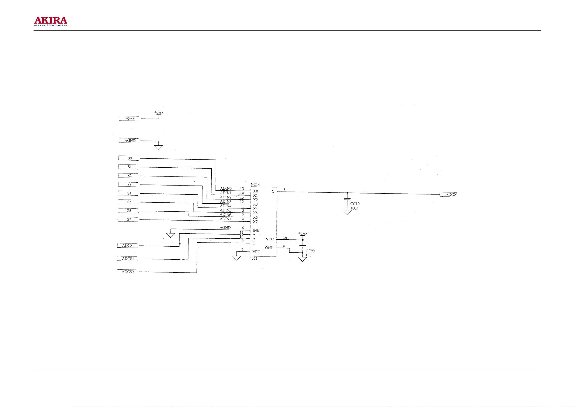
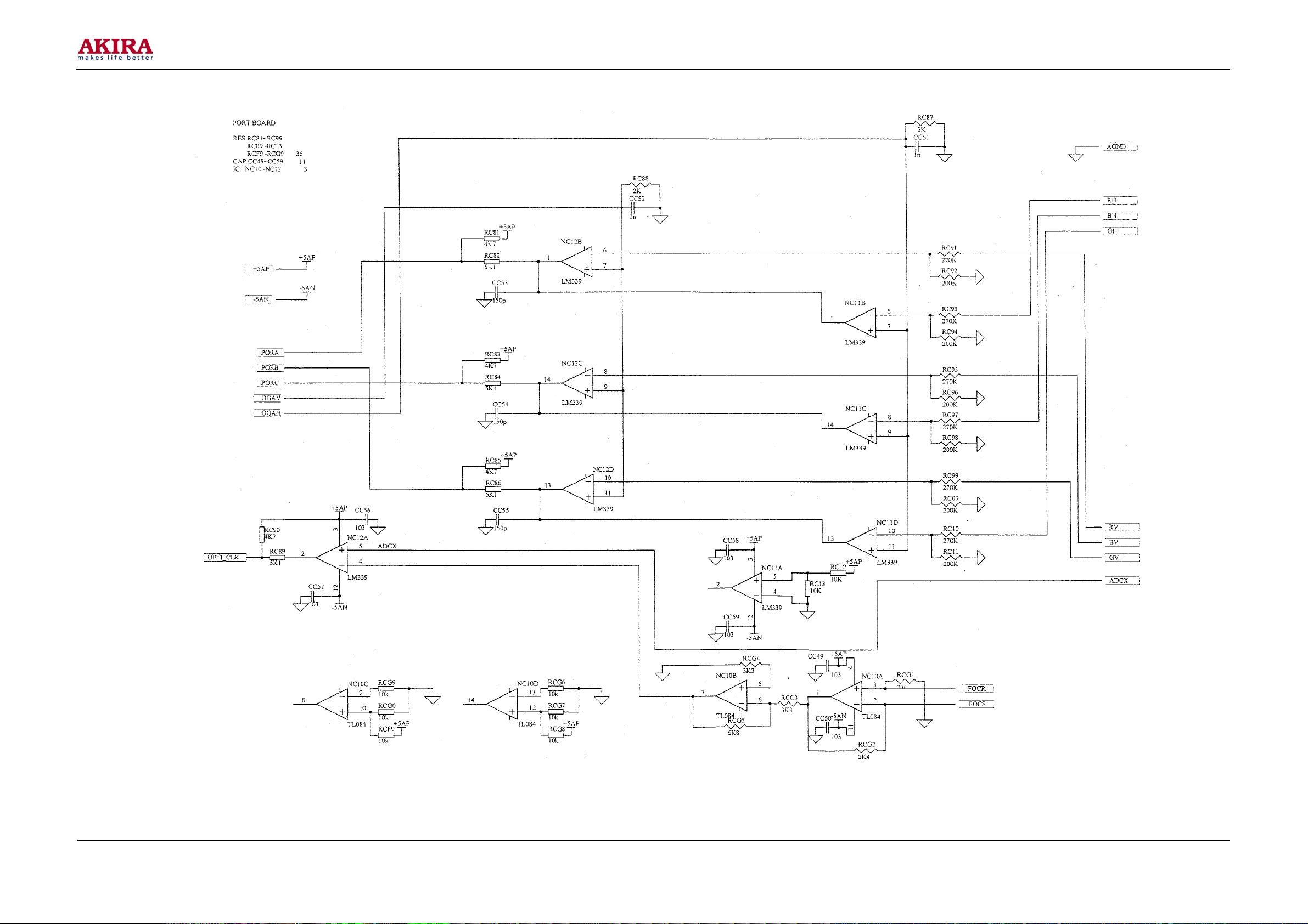
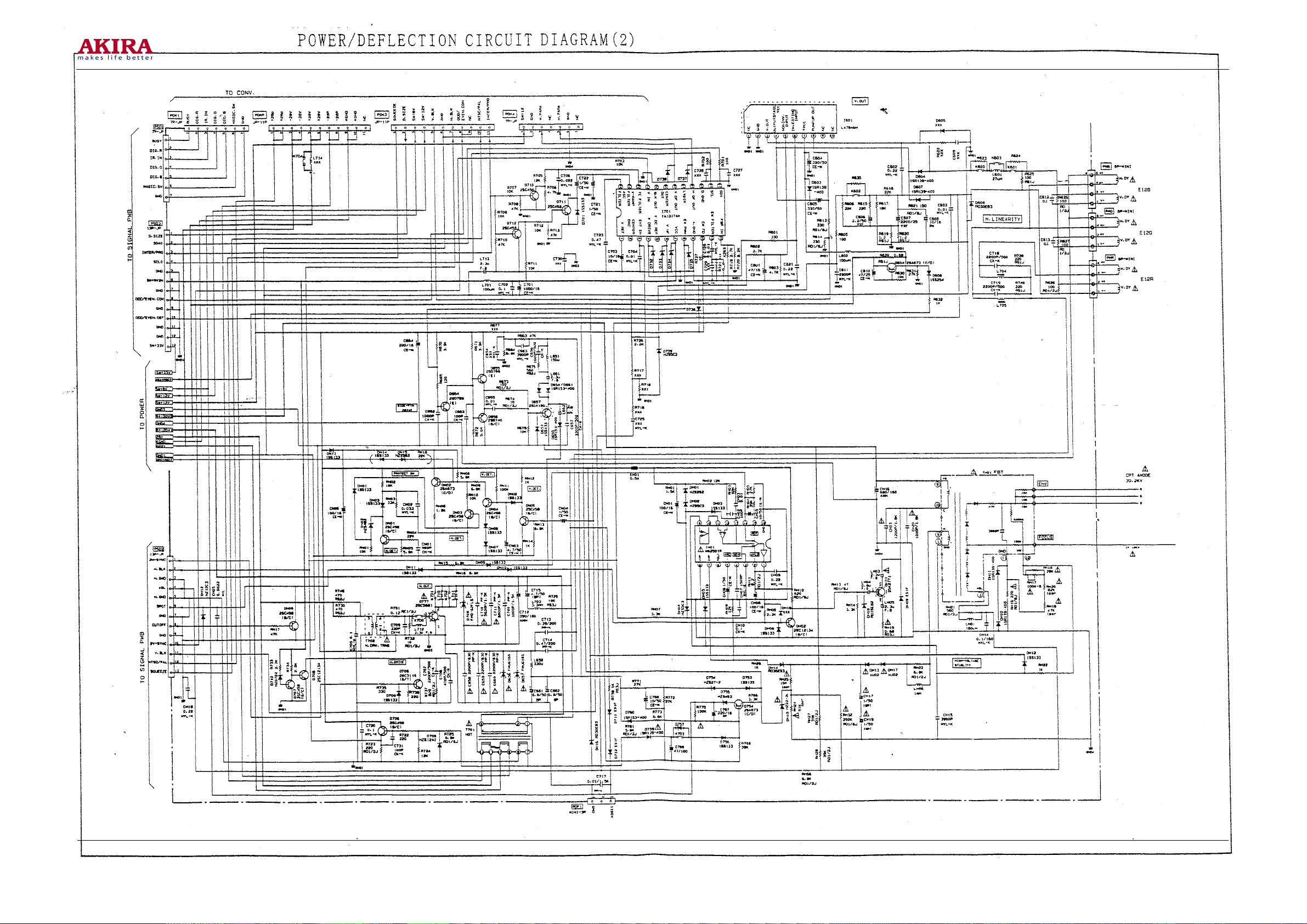
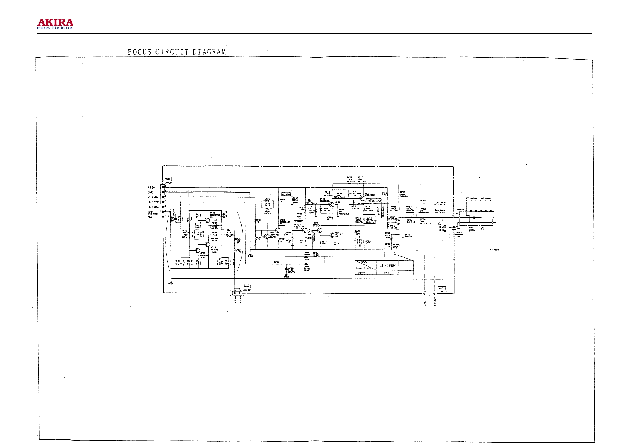
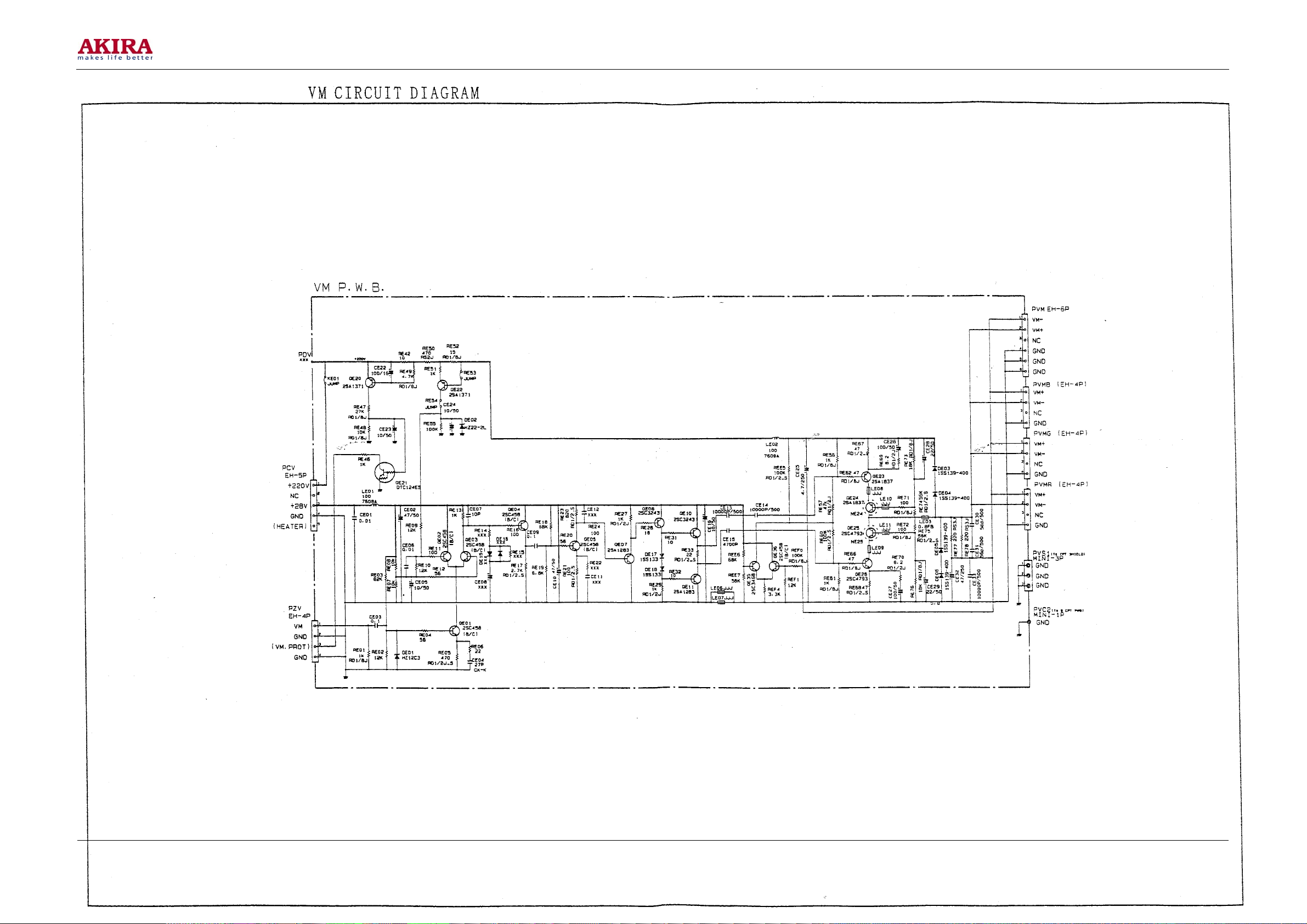
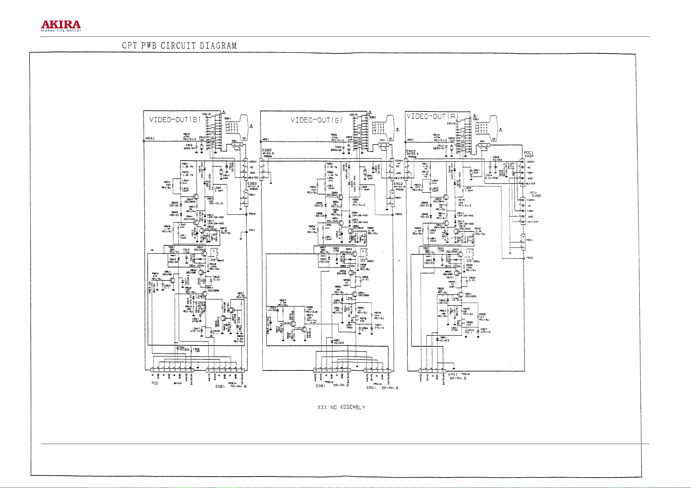
Schematic Circuit Diagram
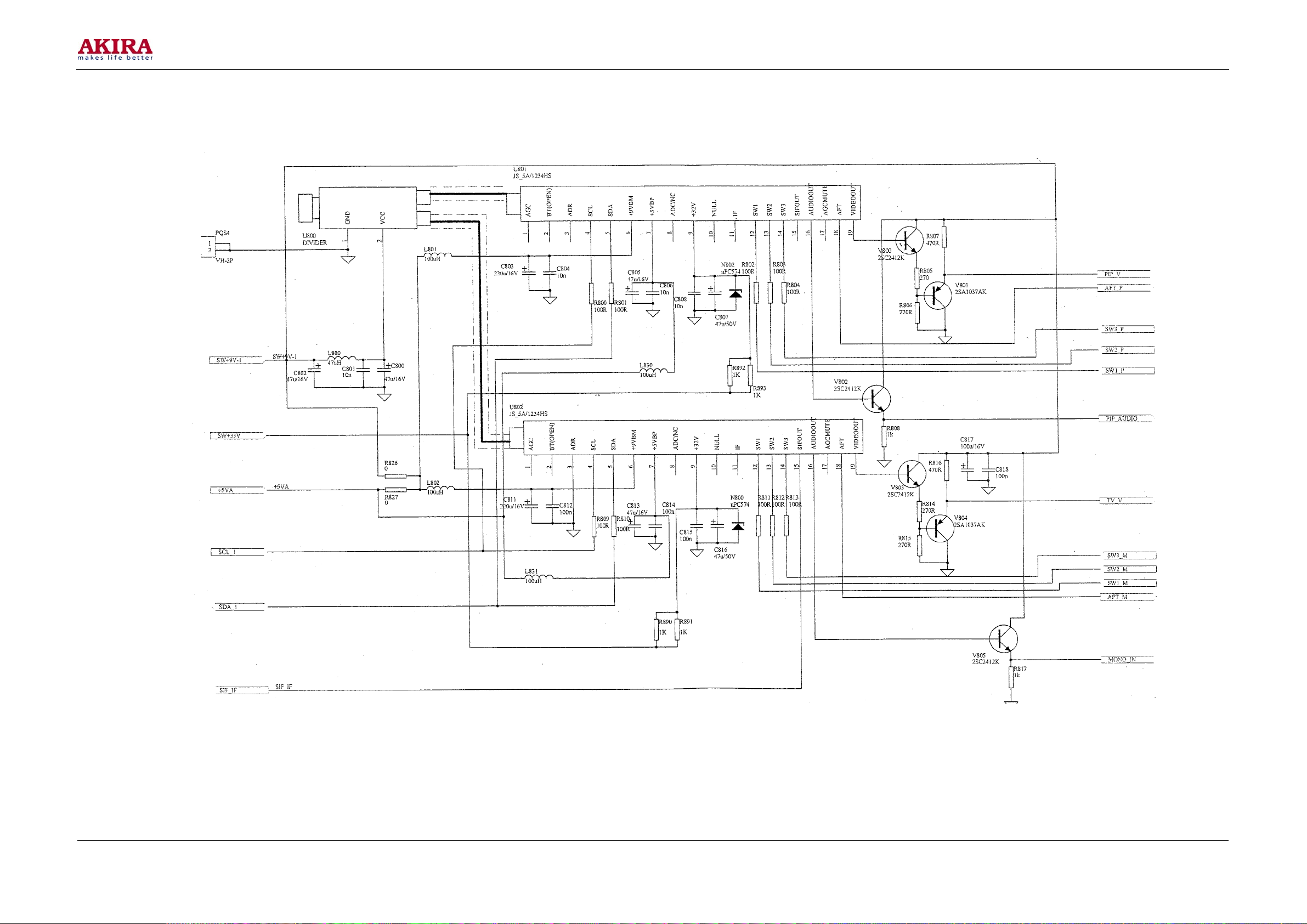
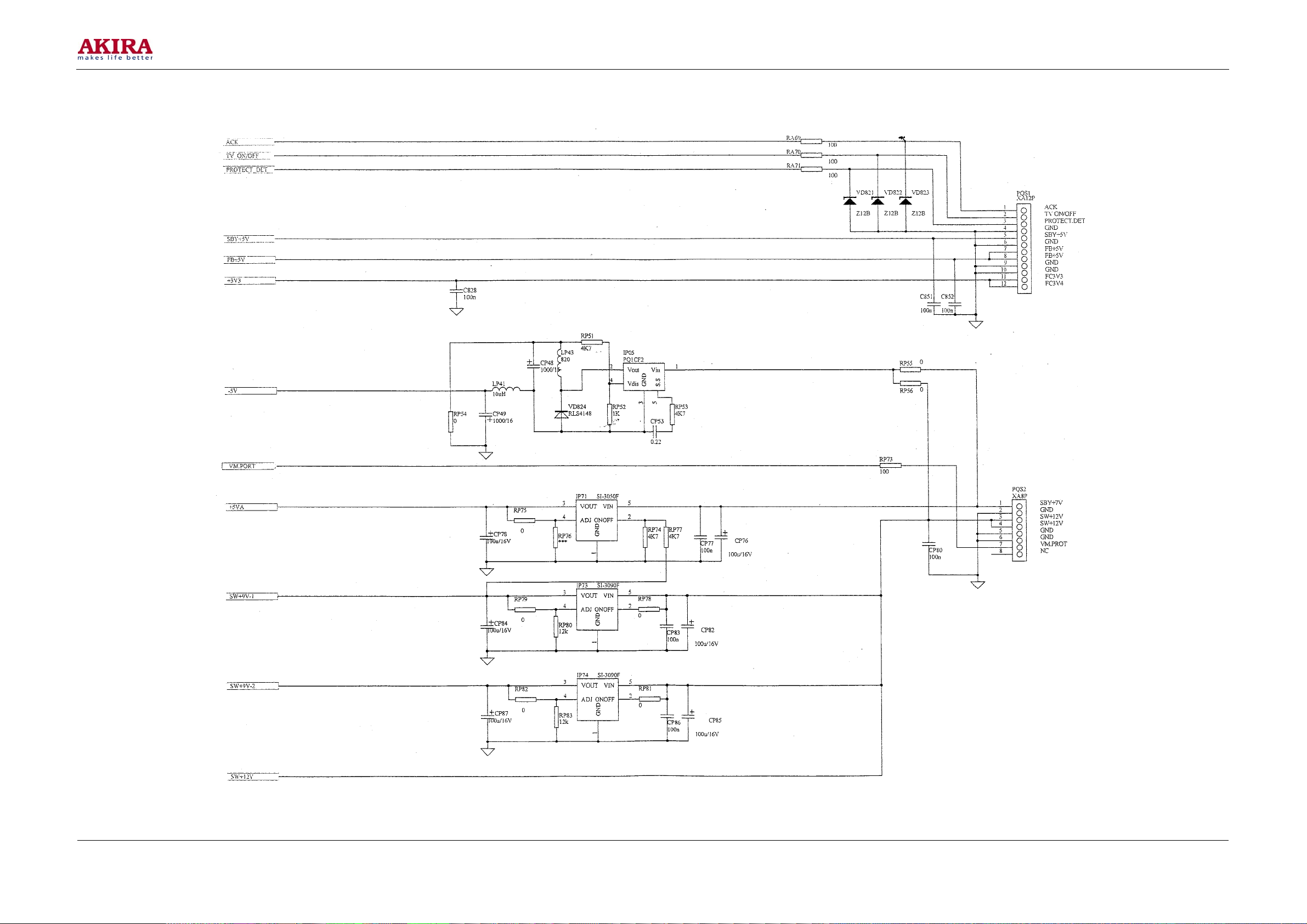
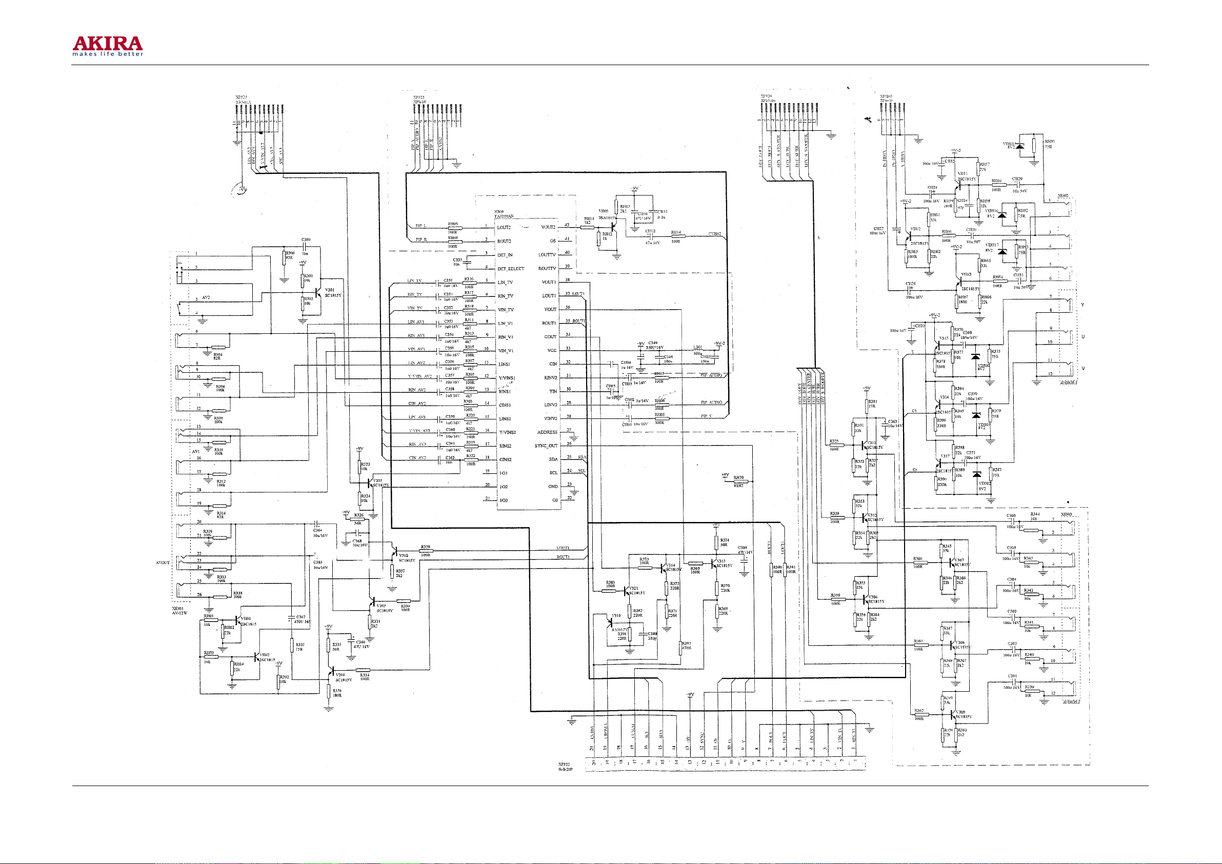
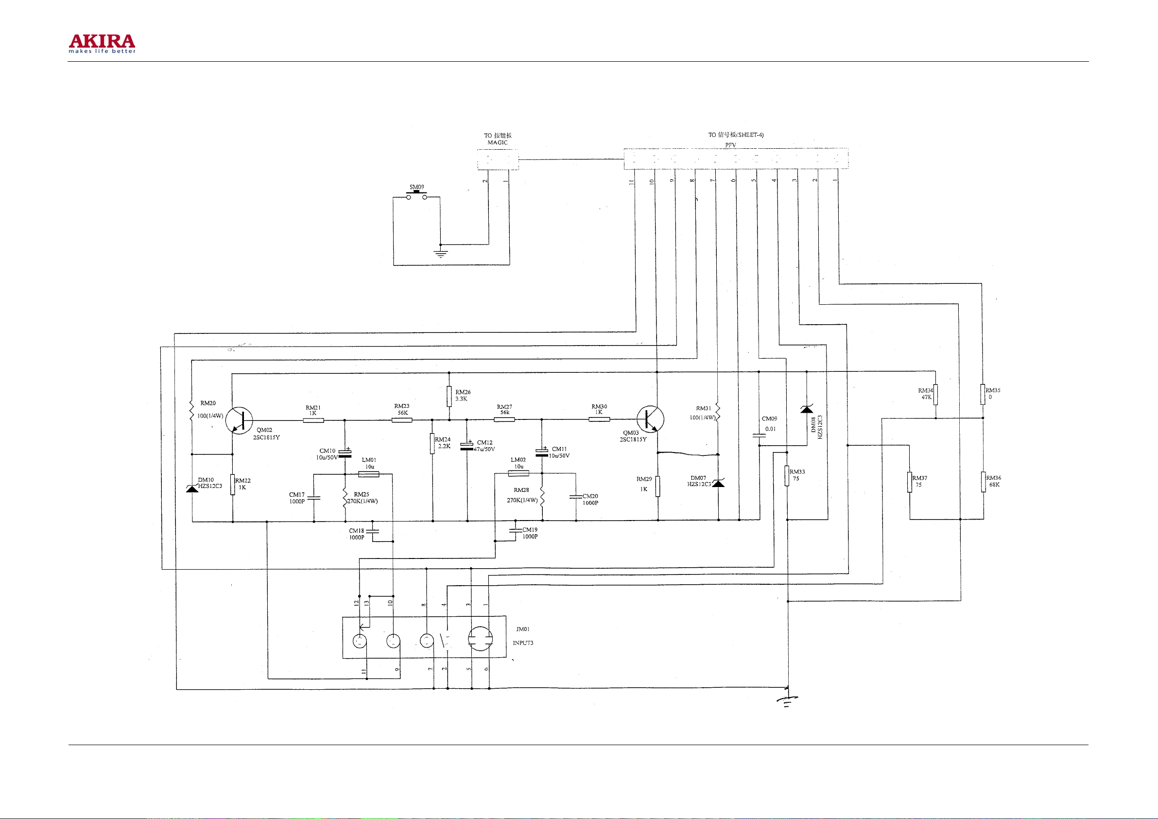
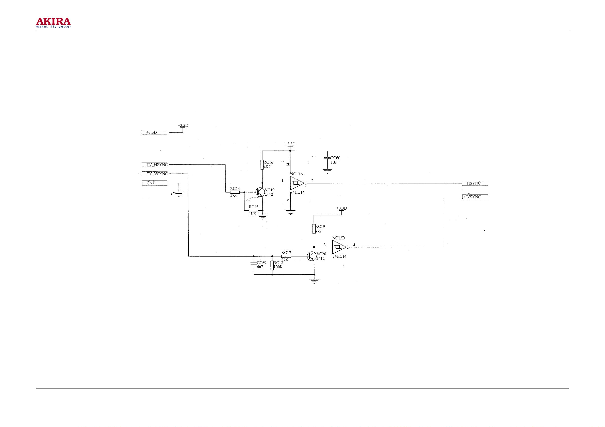
See REAR PROJECTION TV CIRCUIT DIAGRAM NO IET030813 for the circuit diagram.
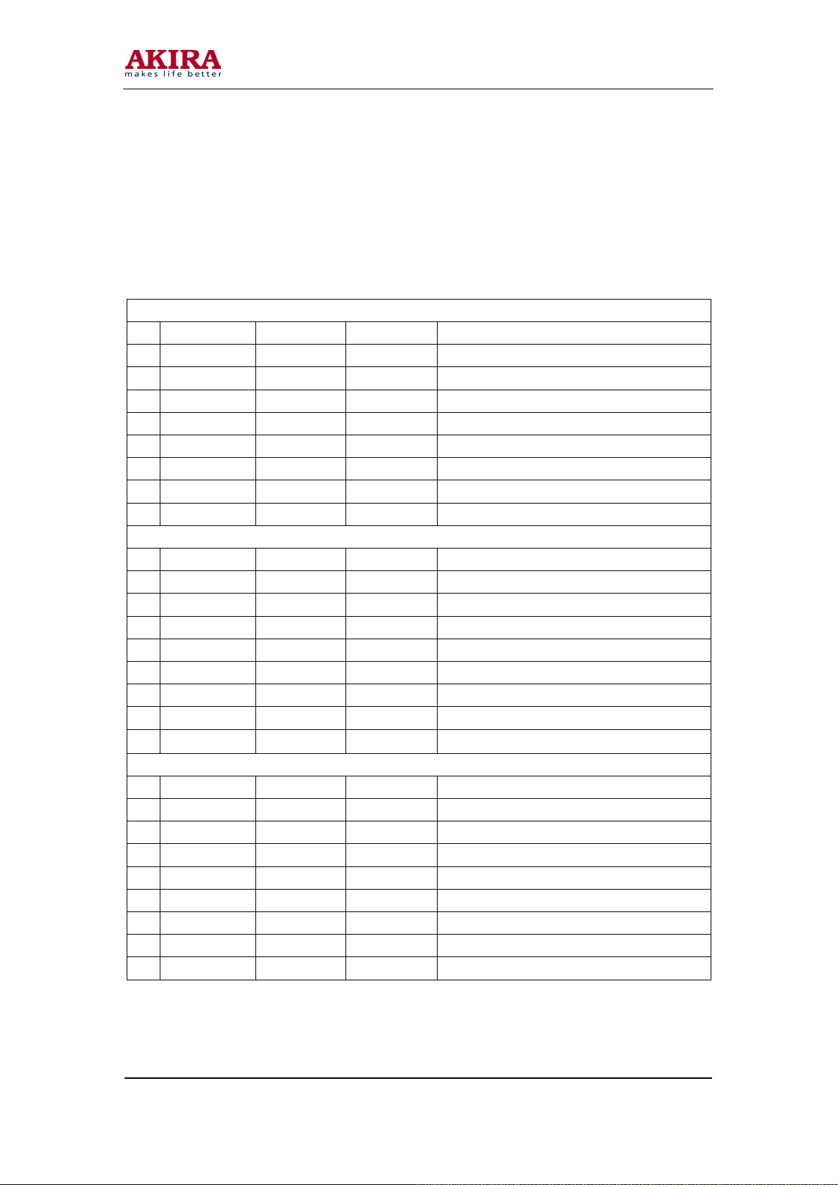
Annexed Table 1, 2 and 3 (The suggestion do not change)
1.100i
PAGE 1/3
No. Name Initial Data Data range Description
1: OSD H 18H 00H-7FH OSD horizontal grid point position
2 OSD V 0AH 00H-7FH OSD vertical grid point position
3 DAC H 1BH 00H-7FH Horizontal phase movement
4 BORDER H 0EH 00H-3FH Horizontal edge position
5 BORDER V 12H 00H-3FH Vertical edge position
6 LINE GAIN 18H 00H-3FH Line gain
7 R CENTER H 00H 00H-FFH Red horizontal DC deflexion
8 R CENTER V 00H 00H-FFH Red vertical DC deflexion
PAGE 2/3
No. Name Initial Data Data range Description
1: G CENTER H 00H 00H-FFH Green horizontal DC deflexion
2 G CENTER V 00H 00H-FFH Green vertical DC deflexion
3 B CENTER H 00H 00H-FFH Blue horizontal DC deflexion
4 B CENTER V 00H 00H-FFH Blue vertical DC deflexion
5 R COARSE H 06H 00H-0FH Horizontal gain of red coarse adjustment
6 R COARSE V 06H 00H-0FH Vertical gain of red coarse adjustment
7 B COARSE V 06H 00H-0FH Horizontal gain of blue coarse adjustment
8 B COARSE V 06H 00H-0FH Vertical gain of blue coarse adjustment
PAGE 3/3
No. Name Initial Data Data range Description
1: HGD 1CH 00H-0FH Setting of vertical line gain
2 HRD 2FH 00H-0FH Setting of vertical line gain
3 OSD BRIG H 04H 00H-0FH OSD horizontal line brightness
4 OSD BRIG V 07H 00H-0FH OSD vertical line brightness
5 OSD RETR H 04H 00H-3CH OSD horizontal return blanking
6 OSD RETR V 0EH 00H-3CH OSD vertical return blanking
7 DAC RETR H 04H 00H-FFH DAC horizontal return blanking
8 DAC RETR V 36H 00H-FFH DAC vertical return blanking
Model No.: PTV-50H08
Version: 1.0
Page 33
-33 -
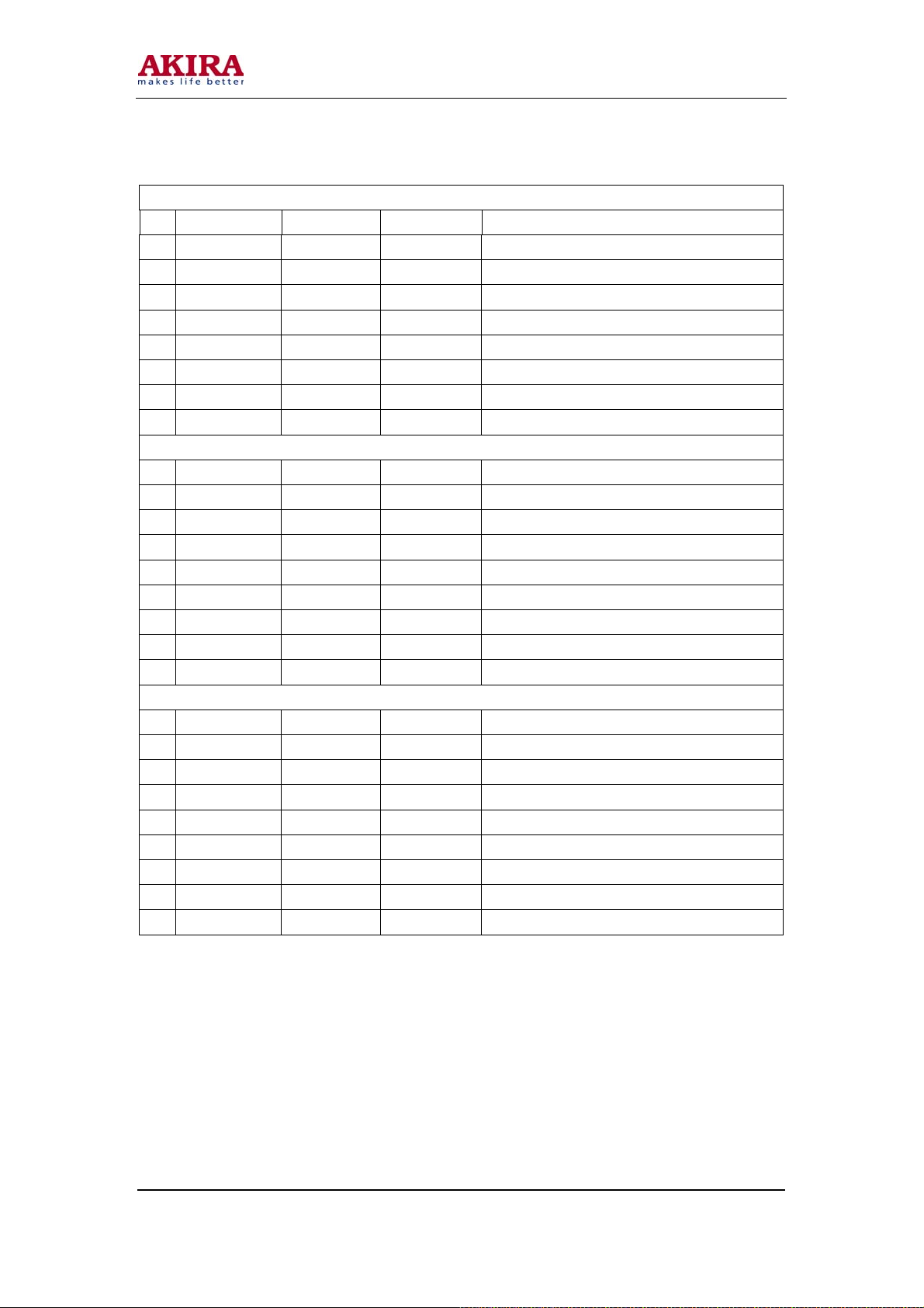
2.60P
PAGE 1/3
No. Name Initial Data Data range Description
1: OSD H 18 00H-7FH OSD horizontal grid point position
2 OSD V 10H 00H-FFH OSD vertical grid point position
3 DAC H 1BH 00H-7FH Horizontal phase movement
4 BORDER H 0EH 00H-3FH Horizontal edge position
5 BORDER V 20H 00H-3FH Vertical edge position
6 LINE GAIN 2AH 00H-3FH Line gain
7 R CENTER H 00H 00H-FFH Red horizontal DC deflexion
8 R CENTER V 00H 00H-FFH Red vertical DC deflexion
PAGE 2/3
No. Name Initial Data Data range Description
1: G CENTER H 00H 00H-FFH Green horizontal DC deflexion
2 G CENTER V 00H 00H-FFH Green vertical DC deflexion
3 B CENTER H 00H 00H-FFH Blue horizontal DC deflexion
4 B CENTER V 00H 00H-FFH Blue vertical DC deflexion
5 R COARSE H 06H 00H-0FH Horizontal gain of red coarse adjustment
6 R COARSE V 06H 00H-0FH Vertical gain of red coarse adjustment
7 B COARSE V 06H 00H-0FH Horizontal gain of blue coarse adjustment
8 B COARSE V 06H 00H-0FH Vertical gain of blue coarse adjustment
PAGE 3/3
No. Name Initial Data Data range Description
1: HGD 1CH 00H-0FH Setting of vertical line gain
2 HRD 2FH 00H-0FH Setting of vertical line gain
3 OSD BRIG H 04H 00H-0FH OSD horizontal line brightness
4 OSD BRIG V 07H 00H-0FH OSD vertical line brightness
5 OSD RETR H 04H 00H-3CH OSD horizontal return blanking
6 OSD RETR V 0EH 00H-3CH OSD vertical return blanking
7 DAC RETR H 04H 00H-FFH DAC horizontal return blanking
8 DAC RETR V 36H 00H-FFH DAC vertical return blanking
Model No.: PTV-50H08
Version: 1.0
Page 34
-34 -
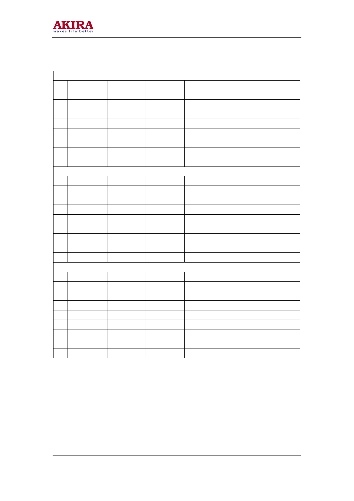
3.1250i
PAGE 1/3
No. Name Initial Data Data range Description
1: OSD H 18H 00H-7FH OSD horizontal grid point position
2 OSD V 1EH 00H-FFH OSD vertical grid point position
3 DAC H 1BH 00H-7FH Setting of horizontal phase movement
4 BORDER H 0EH 00H-3FH Horizontal edge position
5 BORDER V 26H 00H-3FH Vertical edge position
6 LINE GAIN 32H 00H-3FH Setting of line gain
7 R CENTER H 00H 00H-FFH Red horizontal DC deflexion
8 R CENTER V 00H 00H-FFH Red vertical DC deflexion
PAGE 2/3
No. Name Initial Data Data range Description
1: G CENTER H 00H 00H-FFH Green horizontal DC deflexion
2 G CENTER V 00H 00H-FFH Green vertical DC deflexion
3 B CENTER H 00H 00H-FFH Blue horizontal DC deflexion
4 B CENTER V 00H 00H-FFH Blue vertical DC deflexion
5 R COARSE H 06H 00H-0FH Horizontal gain of red coarse adjustment
6 R COARSE V 06H 00H-0FH Vertical gain of red coarse adjustment
7 B COARSE V 06H 00H-0FH Horizontal gain of blue coarse adjustment
8 B COARSE V 06H 00H-0FH Vertical gain of blue coarse adjustment
PAGE 3/3
No. Name Initial Data Data range Description
1: HGD 1CH 00H-0FH Setting of vertical line gain
2 HRD 2FH 00H-0FH Setting of vertical line gain
3 OSD BRIG H 04H 00H-0FH OSD horizontal line brightness
4 OSD BRIG V 07H 00H-0FH OSD vertical line brightness
5 OSD RETR H 04H 00H-3CH OSD horizontal return blanking
6 OSD RETR V 0EH 00H-3CH OSD vertical return blanking
7 DAC RETR H 04H 00H-FFH DAC horizontal return blanking
8 DAC RETR V 36H 00H-FFH DAC vertical return blanking
Model No.: PTV-50H08
Version: 1.0
Page 35
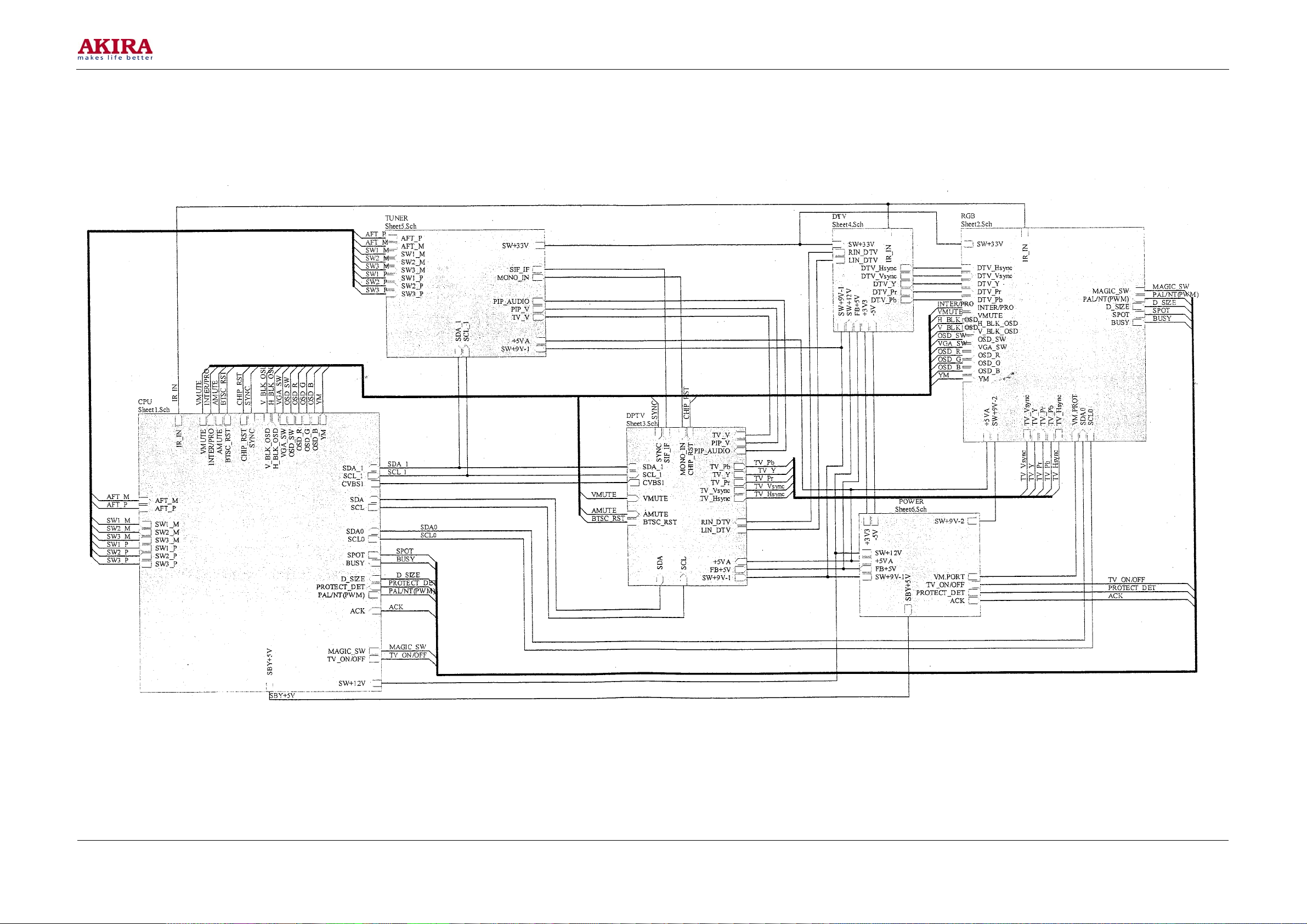
CIRCUIT DIAGRAM
-35 -
Model No.: PTV-50H08
Version: 1.0
Page 36
-36 -
Model No.: PTV-50H08
Version: 1.0
Page 37
-37 -
Model No.: PTV-50H08
Version: 1.0
Page 38
-38 -
Model No.: PTV-50H08
Version: 1.0
Page 39
-39 -
Model No.: PTV-50H08
Version: 1.0
Page 40
-40 -
Model No.: PTV-50H08
Version: 1.0
Page 41
-41 -
Model No.: PTV-50H08
Version: 1.0
Page 42
-42 -
Model No.: PTV-50H08
Version: 1.0
Page 43
-43 -
Model No.: PTV-50H08
Version: 1.0
Page 44
-44 -
Model No.: PTV-50H08
Version: 1.0
Page 45
-45 -
Model No.: PTV-50H08
Version: 1.0
Page 46
-46 -
Model No.: PTV-50H08
Version: 1.0
Page 47
-47 -
Model No.: PTV-50H08
Version: 1.0
Page 48
-48 -
Model No.: PTV-50H08
Version: 1.0
Page 49
-49 -
Model No.: PTV-50H08
Version: 1.0
Page 50
-50 -
Model No.: PTV-50H08
Version: 1.0
Page 51
-51 -
Model No.: PTV-50H08
Version: 1.0
Page 52
-52 -
Model No.: PTV-50H08
Version: 1.0
Page 53
-53 -
Model No.: PTV-50H08
Version: 1.0
Page 54
-54 -
Model No.: PTV-50H08
Version: 1.0
Page 55
-55 -
Model No.: PTV-50H08
Version: 1.0
Page 56
-56 -
Model No.: PTV-50H08
Version: 1.0
Page 57
-57 -
Model No.: PTV-50H08
Version: 1.0
Page 58
-58 -
Model No.: PTV-50H08
Version: 1.0
Page 59
-59 -
Model No.: PTV-50H08
Version: 1.0
Page 60
-60 -
Model No.: PTV-50H08
Version: 1.0
Page 61
-61 -
Model No.: PTV-50H08
Version: 1.0
Page 62
-62 -
Model No.: PTV-50H08
Version: 1.0
Page 63
-63 -
Model No.: PTV-50H08
Version: 1.0
Page 64
-64 -
Model No.: PTV-50H08
Version: 1.0
Page 65
-65 -
Model No.: PTV-50H08
Version: 1.0
Page 66
-66 -
Model No.: PTV-50H08
Version: 1.0
Page 67
-67 -
Model No.: PTV-50H08
Version: 1.0
 Loading...