

Page 1

S
S
S
e
e
e
r
r
r
C
C
C
v
v
v
o
o
o
i
c
i
c
i
c
l
o
l
l
e
e
e
o
o
r
r
r
M
M
M
T
T
T
a
a
a
V
V
V
n
n
n
u
u
u
a
a
a
l
l
l
Page 2

C
C
C
Model:
5
S
Q
C
1
2
-
T
T
T
-
-
2
2
1
1
C
C
Q
Q
S
S
5
5
C
C
C
P
P
P
T
T
T
2
C
h
a
s
C
h
C
h
a
a
s
s
s
s
s
i
s
:
E
T
E
-
2
i
s
:
E
T
E
T
E
E
i
s
:
-
2
-
2
Model no.:CT-21CQS5CPT.doc
version 1.0
Page 3

CONTENTS
SAFETY INSTRUCTIONS AND MAINTENANCE..........................................................................4
SAFETY PRECAUTION.......................................................................................................................................... 5
PRODUCT SAFETY NOTICE................................................................................................................................. 6
SAFETY SYMBOL DESCRIPTION........................................................................................................................ 7
MAINTENANCE ..................................................................................................................................................... 8
SPECIFICATION.................................................................................................................................................... 9
CONTROL & FUNCTION................................................................................................................................... 10
MECHANICA DISASSEMBLING....................................................................................................12
ADJUSTMENTS..................................................................................................................................14
SET-UP ADJUSTMENTS.......................................................................................................................................14
CIRCUIT ADJUSTMENTS.................................................................................................................................... 16
STRUCTURE AND CHASSIS FUNCTION DESCRIPTION.........................................................23
STRUCTION BLOCK DIAGRAM......................................................................................................................... 23
CHASSIS DESCRIPTION...................................................................................................................................... 23
SERVICE DATA..................................................................................................................................25
3
APPENDIX.......................................................................................................................................... 38
CIRCUIT DIAGRAM
PARTS LIST
Please read this manual carefully before service.
Model no.:CT-21CQS5CPT.doc
version 1.0
Page 4

SERVICE SAFETY AND MAINTENANCE
4
WARNING:
BEFORE EXAMINING AND SERVICING
THIS CHASSIS READ CAREFULLY THE
FOLLOWING SAFETY
INSTRUCTIONS.
X-RAY RADIATION PRECAUTION
1. The EHT must be checked every time the TV is serviced to ensure that the CRT does
not emit X-ray radiation as result of excessive EHT voltage. The maximum EHT voltage
permissible in any operating circumstances must not exceed the rated value. When
checking the EHT, use the High Voltage Check procedure in this manual using an
accurate EHT voltmeter.
2. The only source of X-RAY radiation in this TV is the CRT. The TV minimizes X-RAY
radiation, which ensures safety during normal operation. To prevent X-ray radiation,
the replacement CRT must be identical to the original fitted as specified in the parts list.
3. Some components used in this TV have safety related characteristics preventing the
CRT from emitting X-ray radiation. For continued safety, replacement component
should be made after referring the PRODUCT SAFETY NOTICE below.
4. Service and adjustment of the TV may result in changes in the nominal EHT voltage of
the CRT anode. So ensure that the maximum EHT voltage does not exceed the rated
value after service and adjustment.
Model no.:CT-21CQS5CPT.doc
version 1.0
Page 5

5
SAFETY PRECAUTION
WARNING:
REFER SERVICING TO
QUALIFIED SERVICE
PERSONNEL ONLY.
1. The TV has a nominal working EHT voltage. Extreme caution should be exercised when
working on the TV with the back removed.
a. Do not attempt to service this TV if you are not conversant with the precautions
and procedures for working on high voltage equipment.
b. When handling or working on the CRT, always discharge the anode to the TV
chassis before removing the anode cap in case of electric shock.
c. The CRT, if broken, will violently expel glass fragments. Use shatterproof
goggles and take extreme care while handling.
d. Do not hold the CRT by the neck as this is a very dangerous practice.
2. It is essential that to maintain the safety of the customer all power cord forms be replaced
exactly as supplied from factory.
3. Voltage exists between the hot and cold ground when the TV is in operation. Install a
suitable isolating transformer of beyond rated overall power when servicing or connecting
any test equipment for the sake of safety.
4. When replacing ICs, use specific tools or a static-proof electric iron with small power (below
35W).
5. Do not use a magnetized screwdriver when tightening or loosing the deflection yoke
assembly to avoid electronic gun magnetized and decrement in convergence of the CRT.
6. When remounting the TV chassis, ensure that all guard devices, such as nonmetal control
buttons, switch, insulating sleeve, shielding cover, isolating resistors and capacitors,
are installed on the original place.
7. Replace blown fuses within the TV with the fuse specified in the parts list. 8. When
replacing wires or components to terminals or tags, wind the leads around the terminal
before soldering. When replacing safety components identified by the international
hazard symbols on the circuit diagram and parts list, it must be the company-approved
type and must be mounted as the original.
8. Keep wires away from high temperature components.
Model no.:CT-21CQS5CPT.doc
version 1.0
Page 6

PRODUCT SAFETY NOTICE
CAUTION:
FOR YOUR PROTECTION
THE FOLLOWING PRODUCT SAFETY NOTICE
SHOULD BE READ CAREFULLY BEFORE
OPERATING AND SERVICING THIS TV SET.
1. Many electrical and mechanical components in this chassis have special safety-related
characteristics. These characteristics are often passed unnoticed by a visual inspection
and the X-ray radiation protection afforded by them cannot necessarily be obtained by
using replacements rated at higher voltages or wattage, etc. Components which have
these special safety characteristics in this manual and its supplements are identified by the
international hazard symbols on the circuit diagram and parts list. Before replacing any of
these components read the parts list in this manual carefully. Substitute replacement
components which do not have the same safety characteristics as specified in the parts list
may create X-ray radiation.
2. Do not slap or beat the cabinet or CRT, since this may result in fire or explosion.
3. Never allow the TV sharing a plug or socket with other large-power equipment. Doing so
may result in too large load, causing fire.
4. Do not allow anything to rest on or roll over the power cord. Protect the power cord from
being walked on, modified, cut or pinched, particularly at plugs.
5. Do not place any objects, especially heavy objects and lightings, on top of the TV set. Do
not install the TV near any heat sources such as radiators, heat registers, stove, or other
apparatus that produce heat.
6. Service personnel should observe the SAFETY INSTRUCTIONS in this manual during use
and servicing of this TV set. Otherwise, the resulted damage is not protected by the
manufacturer.
6
Model no.:CT-21CQS5CPT.doc
version 1.0
Page 7
7
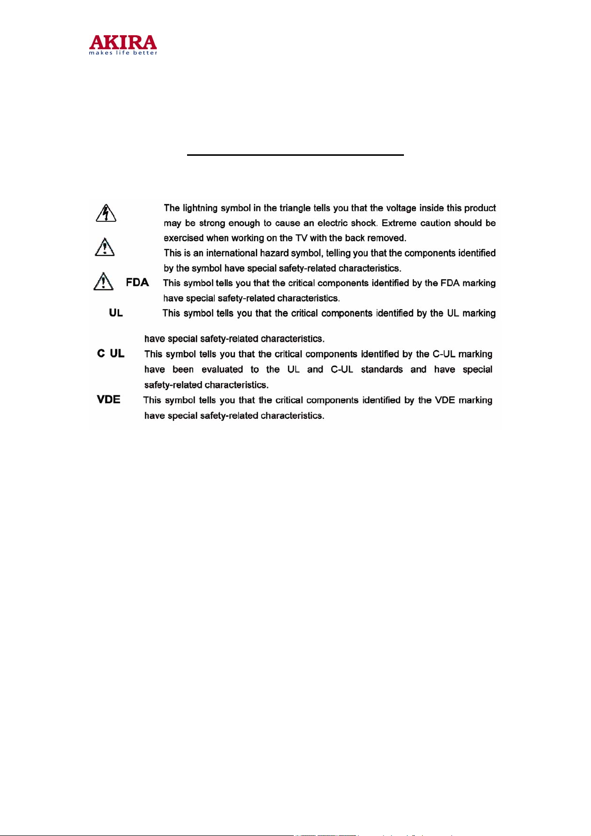
SAFETY SYMBOL DESCRIPTION
Model no.:CT-21CQS5CPT.doc
version 1.0
Page 8

1. Place the TV set on a stable stand or base that is of adequate size and strength to
prevent it from being accidentally tipped over, pushed off, or pulled off. Do not
place the set near or over a radiator or heat register, or where it is exposed to direct
sunlight.
2. Do not install the TV set in a place exposed to rain, water, excessive dust,
mechanical vibrations or impacts.
3. Allow enough space (at least 10cm) between the TV and wall or enclosures for
proper ventilation.
4. Slots and openings in the cabinet should never be blocked by clothes or other
objects.
5. Please power off the TV set and disconnect it from the wall immediately if any
abnormal condition are met, such as bad smell, belching smoke, sparkling,
abnormal sound, no picture/sound/raster. Hold the plug firmly when disconnecting
the power cord.
6. Unplug the TV set from the wall outlet before cleaning or polishing it. Use a dry soft
cloth for cleaning the exterior of the TV set or CRT screen. Do not use liquid
cleaners or aerosol cleaners.
8
MAINTENANCE
Model no.:CT-21CQS5CPT.doc
version 1.0
Page 9

SPECIFICATION
RF System : Colour / Sound system : PAL/SECAM BG/DK/I, NTSC-M (4.43 & 3.58)
Programs Preset : 236 ( 0 ~ 235 )
Antenna Input : 75 (unbalanced)
Power Source : 110 ~ 240V 50/60Hz
Designs and specifications are subject to change without notice.
9
Model no.:CT-21CQS5CPT.doc
version 1.0
Page 10
CONTROL & FUNCTION
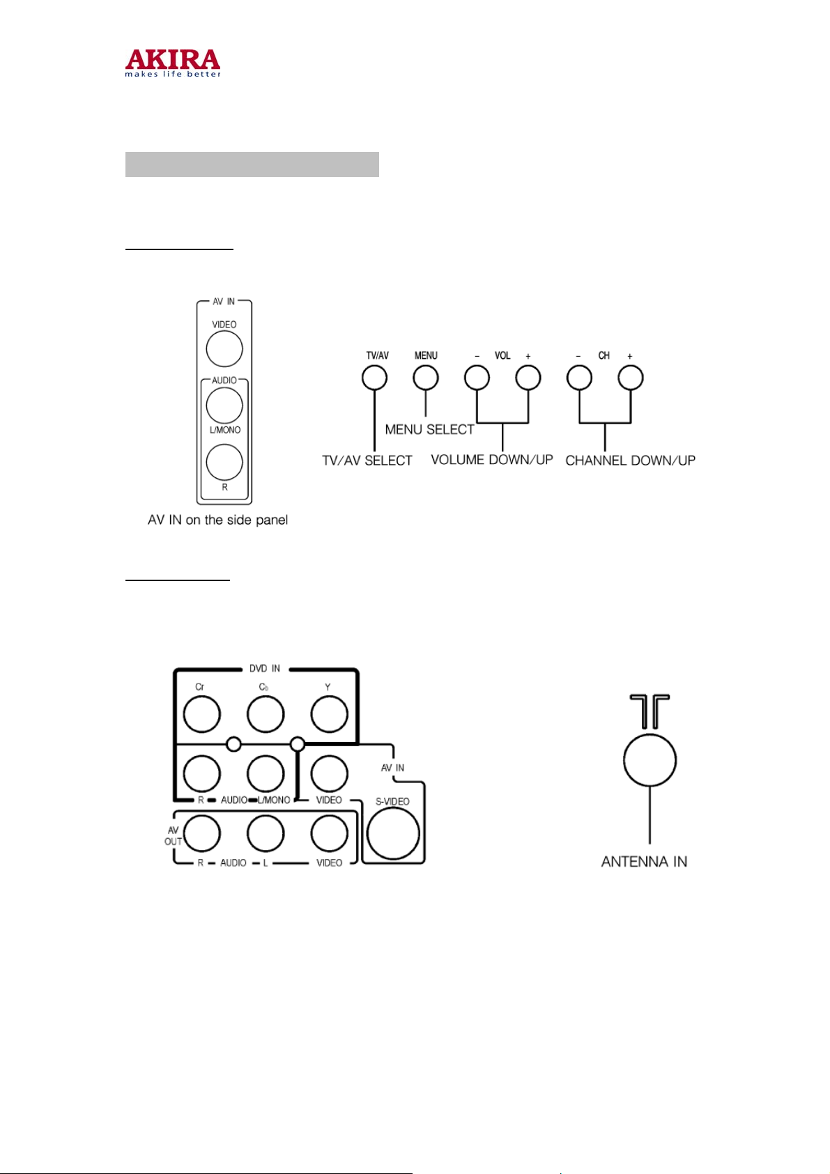
Front Panel
10
Rear Panel
* The pictures showed are for function illustration. Please refer to the TV as the standard.
Model no.:CT-21CQS5CPT.doc
version 1.0
Page 11
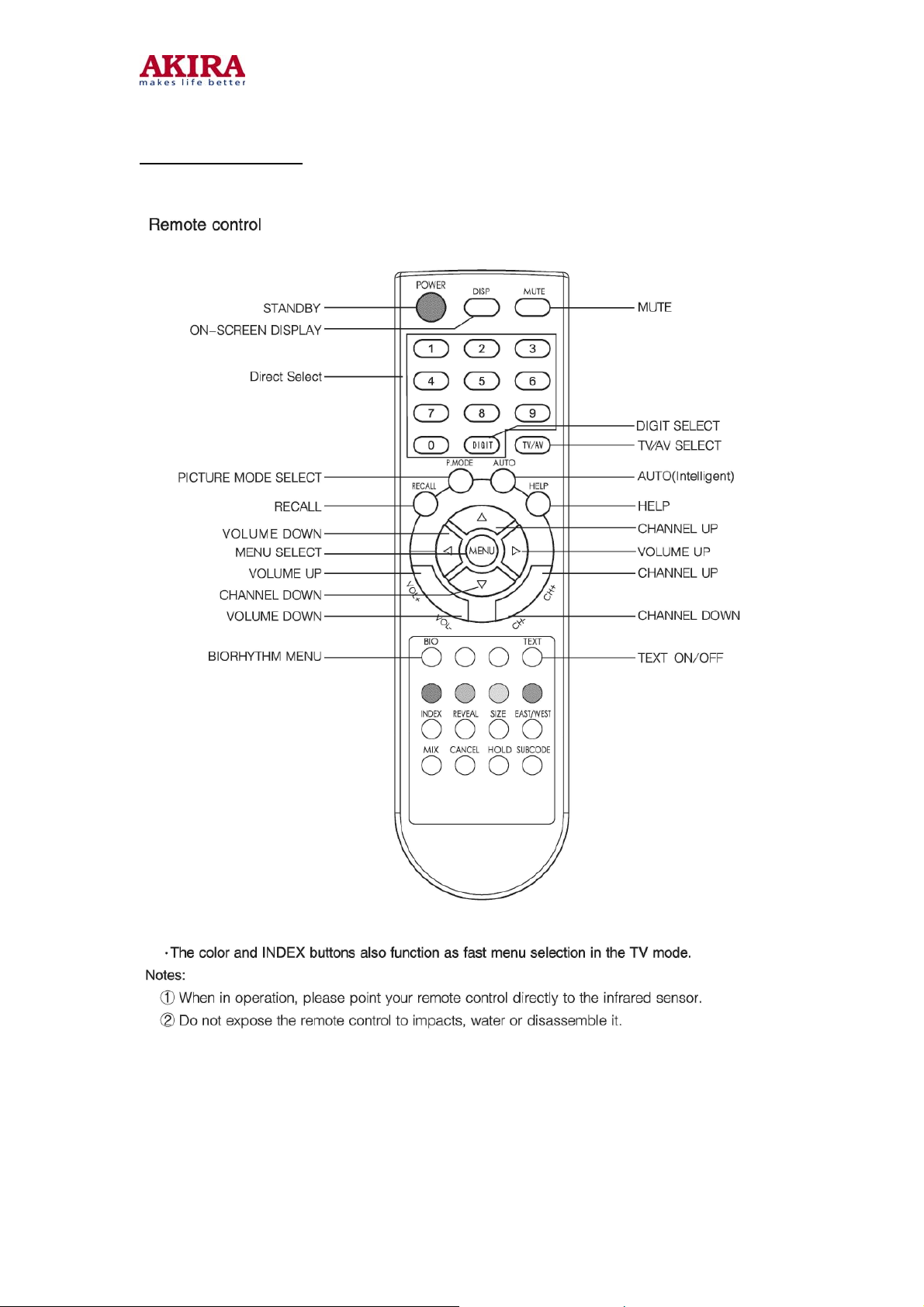
Remote Control
11
Model no.:CT-21CQS5CPT.doc
version 1.0
Page 12

MECHANICA DISASSEMBLIES
CABINET BACK REMOVAL
1. Refer to Figure 1, remove 7screws.
2. Pull off cabinet back and remove.
12
CHASSIS REMOVAL
1. Remove cabinet back.
2. Discharge the picture tube anode (2
grounding lead).
3. Disconnect Degaussing coil socket (KE). Picture tube socket, Deflection yoke connector
(KDY). Speaker connectors (KL and KR), and 2
4. Remove chassis completely by sliding it straight back.
nd
anode lead) to the dag coating (picture tube
nd
anode lead.
Model no.:CT-21CQS5CPT.doc
version 1.0
Page 13
13
PICTURE TUBE REMOVAL
CAUTION: Do not disturb the deflection yoke or magnet assembly on the picture tube Neck.
Care must be taken to keep these assemblies intact, unless picture tube is being replaced.
Discharge the picture tube to the coating before handing the Tube.
1. Remove chassis, referring to Chassis Removal instructions.
2. Place cabinet front face down on the soft surface.
3. Remove the screw one ach corner of the picture tube and GENTLY lift the picture tube out
of the cabinet.
4. Install a replacement picture tube in reverse order.
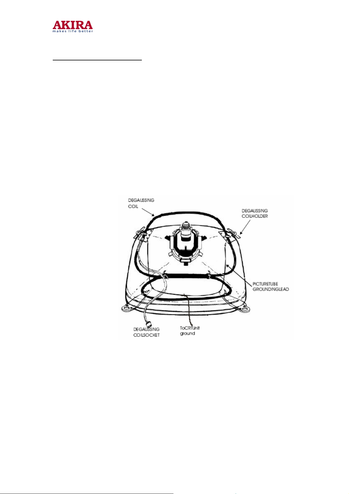
5. Properly install the degaussing coil and picture tube grounding lead on the picture tube.
SeeFigure2.
Note: If the Picture Tube is being replaced, mount the Degaussing Coi l on the picture tube. See
following Figure1.Cabinet Back Removal
Model no.:CT-21CQS5CPT.doc
version 1.0
Page 14

ADJUSTMENTS
1 SET-UP ADJUSTMENTS
The following adjustments should be made when a complete realignment is required or a
new picture tube is installed.
Perform the adjustments in the following order:
Color purity
Convergence
White balance
Notes:
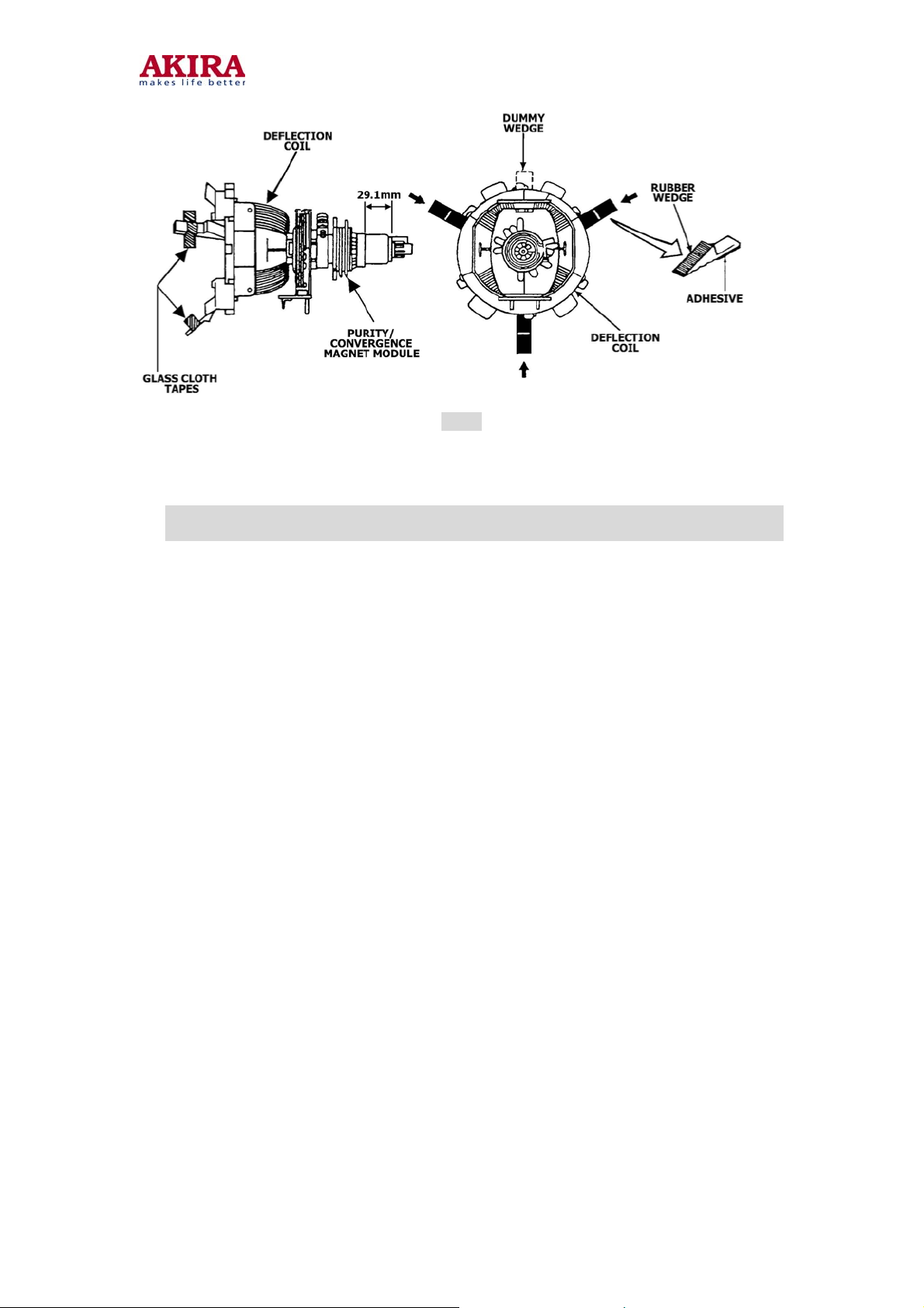
The purity/convergence magnet assembly and rubber wedges need mechanical positioning.
For some picture tubes, purity/ convergence adjustments are not
required.
14
1.1 Color Purity Adjustment
Preparation:
Before starting this adjustment, adjust the vertical sync, horizontal sync, vertical amplitude
and focus.
•Face the TV set north or south.
•Connect the power plug into the wall outlet and turn on the main power switch of the TV
set. •Operate the TV for at least 15 minutes.
•Degauss the TV set using a specific degaussing coil.
•Set the brightness and contrast to maximum.
•Counter clockwise rotate the R /B low brightness potentiometers to the end and rotate the
green low brightness potentiometer to center.
•Receive green raster pattern signals.
•Loosen the clamp screw holding the deflection yoke assembly and slide it forward or
backward to display a vertical green zone on the screen. Rotate and spread the tabs of the
purity magnet around the neck of the CRT until the green zone is located vertically at the
center of the screen. •Slowly move the deflection yoke assembly forward or backward until
a uniform green screen is obtained.
•Tighten the clamp screw of the assembly temporarily. Check purity of the red raster and
blue raster until purities of the three rasters meet the requirement.
Model no.:CT-21CQS5CPT.doc
version 1.0
Page 15
15
Fig. 1
1.2 Convergence Adjustment
Preparation: Before attempting any convergence adjustment, the TV should be
operated for at least 15 minutes.
•Center convergence adjustment.
•Receive dot pattern.
•Adjust the brightness/contrast controls to obtain a sharp picture.
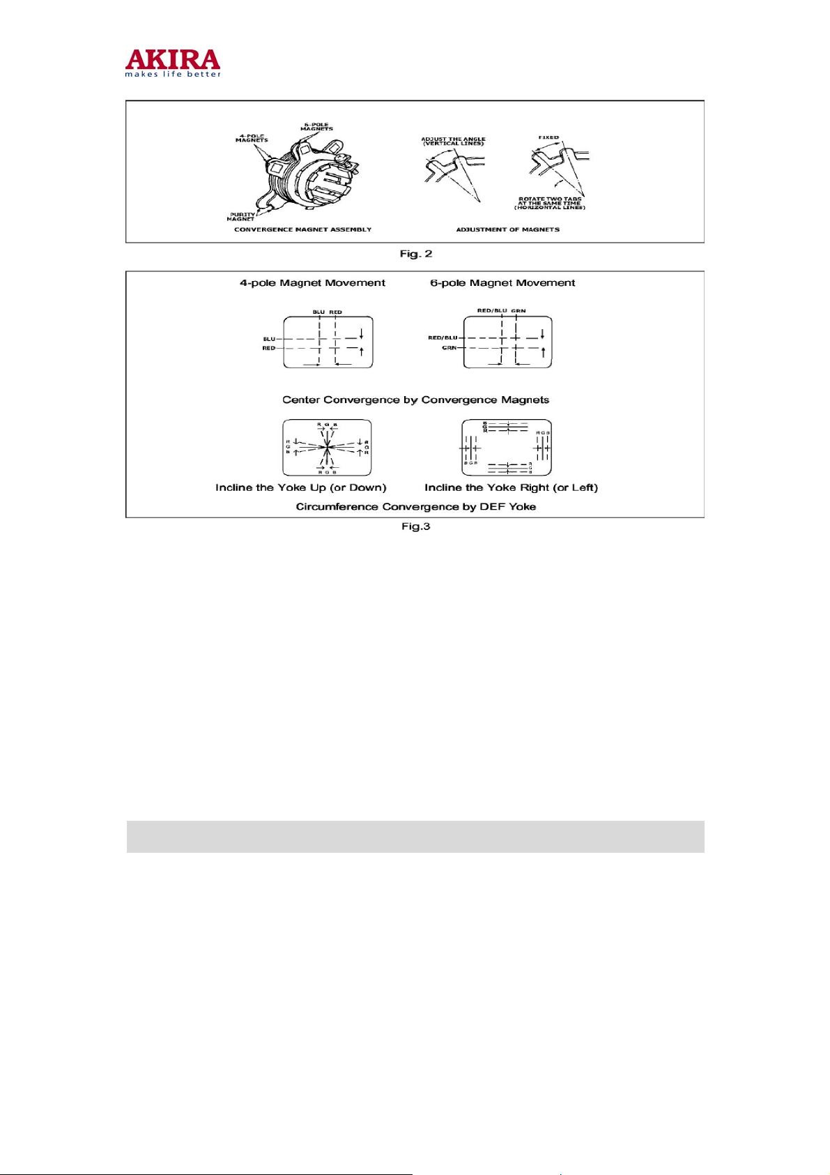
•Adjust two tabs of the 4-pole magnet to change the angle between them and red and blue
ertical lines are superimposed each other on the center of the screen.
•Turn both tabs at the same time keeping the angle constant to superimpose red and blue
horizontal on the center of the screen.
•Adjust two tabs of the 6-pole magnet to superimpose red/blue line and green line.
•Remember red and blue movement. Repeat steps 2.1.3 2. 1.5 until optimal convergence
is obtained.
•Circumference convergence adjustment.
•Loosen the clamp screw holding the deflection yoke assembly and allow it tilting.
•Temporarily put the first wedge between the picture tube and deflection yoke assembly.
Move front of the deflection yoke up or down to obtain better convergence in circumference.
Push the mounted wedge in to fix the yoke temporarily.
•Put the second wedge into bottom.
•Move front of the deflection yoke to the left or right to obtain better convergence in
circumference.
•Fix the deflection yoke position and put the third wedge in either upper space. Fasten the
deflection yoke assembly on the picture tube.
•Detach the temporarily mounted wedge and put it in either upper space. Fasten the
deflection yoke assembly on the picture tube.
•After fastening the three wedges, recheck overall convergence and ensure to get optimal
convergence. Tighten the lamp screw holding the deflection yoke assembly.
Model no.:CT-21CQS5CPT.doc
version 1.0
Page 16
16
1.3 White Balance Adjustment
Generally, white balance adjustment is made with professional equipment. It’s not practical to
get good white balance only through manual adjustment. For TVs with I2C bus control,
change the bus data to adjust white balance.
2 CIRCUIT ADJUSTMENTS
Preparation:
Circuit adjustments should be made only after completion of set-up adjustments.
Circuit adjustments can be performed using the adjustable components inside the TV set.
For TVs with 2 I C bus control, first change the bus data.
2.1 Degaussing
A degaussing coil is built inside the TV set. Each time the TV is powered on, the
degaussing coil
will automatically degauss the TV. If the TV is magnetized by external strong magnetic field,
causing color spot on the screen, use a specific degausser to demagnetize the TV in the
following ways. Otherwise, color distortion will be shown on the screen.
•Power on the TV set and operate it for at least 15 minutes.
•Receive red full-field pattern.
•Power on the specific degausser and face it to the TV screen.
•Turn on the degausser. Slowly move it around the screen and slowly take it away
from the TV
.•Repeat the above steps until the TV is degaussed completely.
Model no.:CT-21CQS5CPT.doc
version 1.0
Page 17
17
2.2 Confirmation and Adjustment for Voltage
Caution: +B voltage has close relation to high voltage. To prevent X-ray radiation, set +B
voltage to the rated value
•Make sure that the supply voltage is within the range of the rated value.
•Connect a digital voltmeter to the voltage output terminal of the main PCB. Power on the
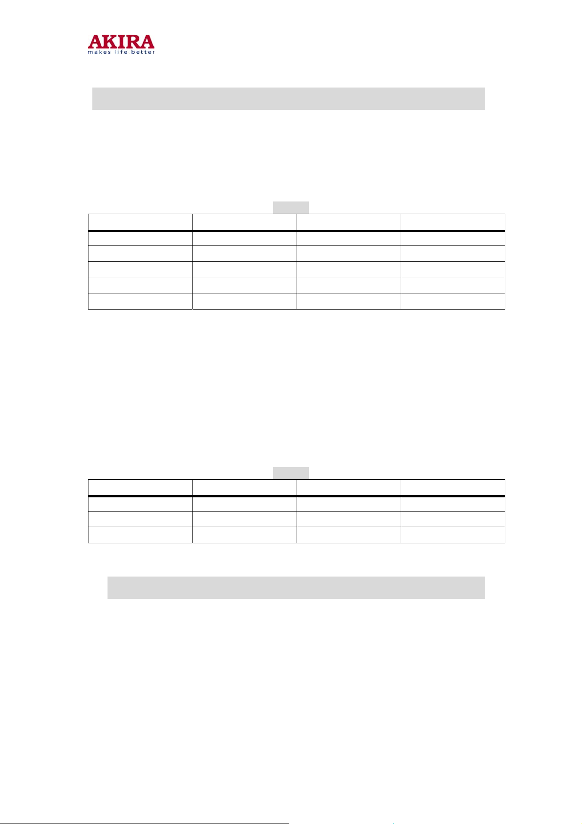
TV and set the brightness and sub-brightness to minimum. Ensure that the voltage from
the main PCB reads as follows.
•Regulate voltage adjustment components on the power section until the +B the voltage
reaches the rated value.
Table 1
Test Point Voltage Test Point Voltage
TP-115V 117V±1.5V TP-18V 23V±2V
TP-15V 15.5V±1V TP-5V 5V±0.5V
TP-3.3V 3.3V±0.3V TP-8V 8V±1V
TP-12V 13V±2V TP--12V -13V±2V
TP-195V 196V±2V
Note: It’s impossible to check the power part separately from the main chassis board as
the part is mounted on the main chassis board. The power components, etc. should be
checked for burnout when power-on. If burned out, do not power on the TV again until the
cause is found out.
2.3 High Voltage Inspection
Measure voltages of test points on the main PCB with the digital voltmeter. Measure the
CRT high voltage with the high-voltage testing equipment and heater voltage with the
high-frequency effective voltmeter. The rated values are shown as below.
Table 2
Test Point Voltage Test Point Voltage
Negative of VD49 1 1 96±2V 14"GS_CRT_anode 22±1.5KV
21 "FS_CRT_anode 26±1.5KV 21 "PF-CRT-anode 27±1.5KV
Heater 6.3±0.3Vrms
2.4 Focus Adjustment
Caution: Dangerously high voltages are present inside the TV. Extreme caution
should be exercised when working on the TV with the back removed.
•After removing the back cover, look for the FBT on the main PCB. There should be a
FCB (FOCUS) on the FBT.
•Power on the TV and preheat it for 15 min.
•Receive a normal TV signal. Rotate knob of the FCB until you get a sharp picture
Model no.:CT-21CQS5CPT.doc
version 1.0
Page 18
2.5 SERVICE mode
To enter the SERVICE mode
Set the volume to 0. Then press and hold the MUTE button on the remote control,
and press the MENU button on the TV to enter the SERVICE mode. To exit from the
SERVICE mode, turn off the TV set by the POWER button on the remote control.
Caution: The user service mode adjustment can be changed only when service
personnel
adjust the whole set data during servicing. As the control data have dramatic effects on
functions
and performance of the TV, service personnel should not tell user how to enter the
SERVICE mode to avoid improper data settings.
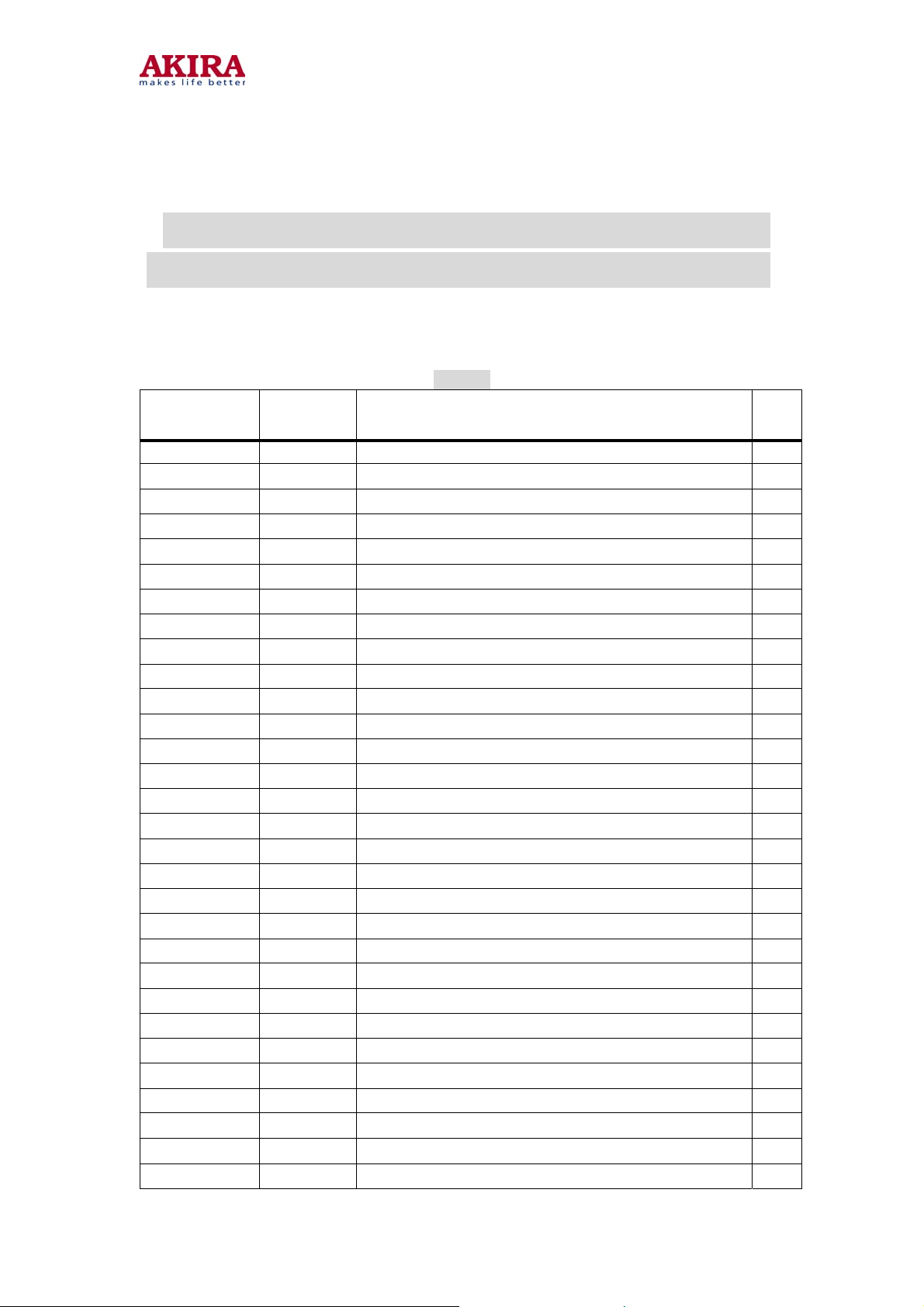
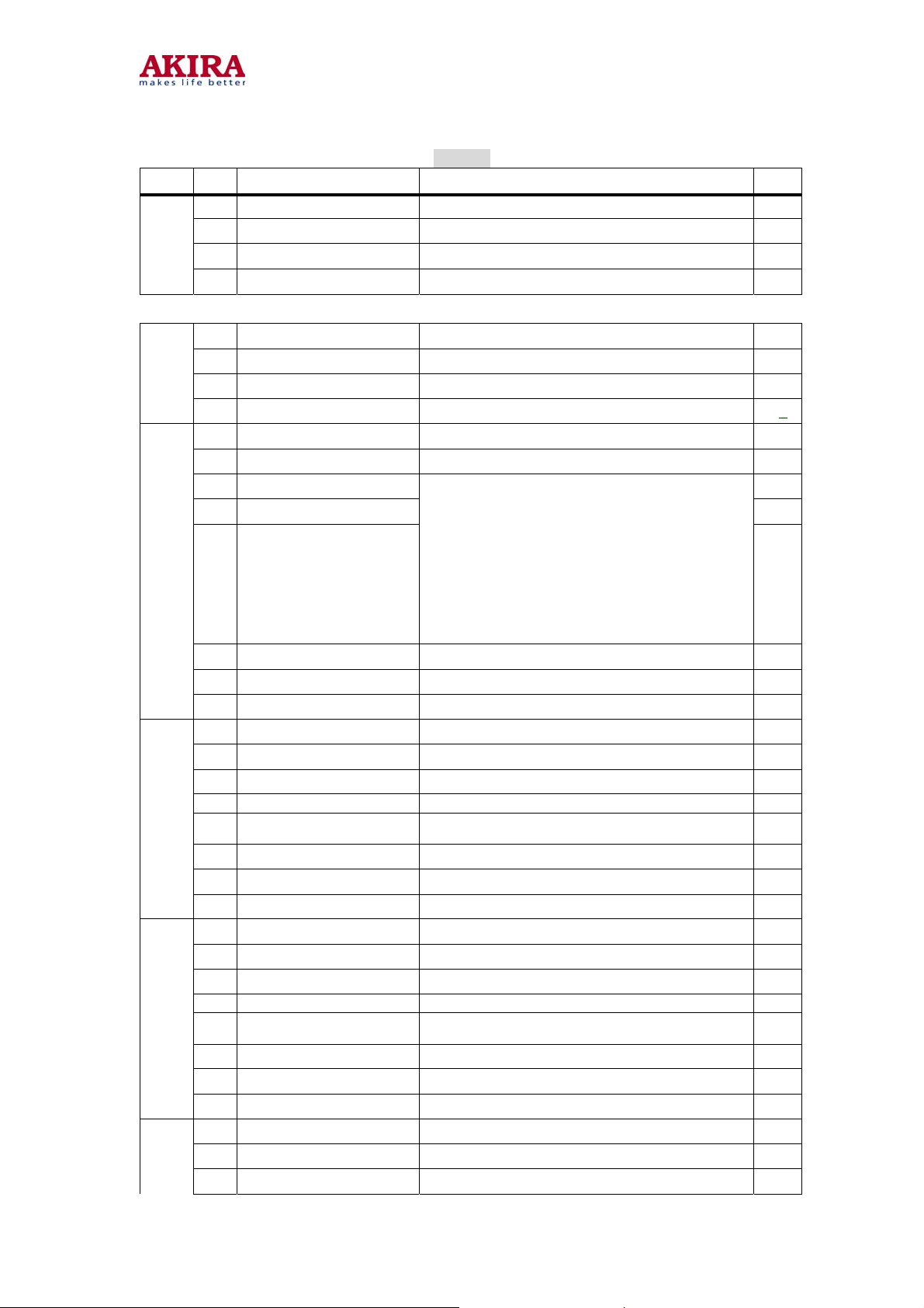
Adjustments and bus data
Table 3
SERVICE
Mode
STS0/1/2/3/4 UOC system surveillance display
IFP1 00 IF PRESET VALUE 1 #
IFP2 00 IF PRESET VALUE2 #
TINT 20 BASE BAND TINT CONTROL #
TWBK 88 TIME OF “WIDE BLANKING” #
PWL 15 Peak white limted #
OIF 20 Off-set if demodulatour #
5HP/6HP
5HB/6HB
5HSH/6HSH adjustable HORIZONTAL SHIFT
5HZD/6HZD 0A DVD HORIZONTAL SHIFT
5EWW/6EWW adjustable E-W WIDTH
5EWP/6EWP adjustable E-W PARABOLA WIDTH
5UCR/6UCR adjustable E-W UPPER CORNER PARABOLA
5LCR/6LCR adjustable E-W BOTTOM CORNER PARABOLA
5TC/6TC
5VSL/6VSL adjustable VERTICAL SLOPE
5VAM/6VAM adjustable VERTICAL AMPLITUDE
5SCL/6SCL adjustable VERTICAL S CORRECTION
5VSH/6VSH adjustable VERTICAL SHIFT
5VZD/6VZD 00 DVD VERTICAL SHIFT
5VOF/6VOF 26 OSDVERTICAL SHIFT
RED 20 BLACK LEVEL OFFSET:R
GRN 20 BLACK LEVEL OFFSET:G
WPR 1F WHITE POINT R
WPG 1F WHITE POINT G
WPB 1F WHITE POINT B
DRED 00 DVD BLACK LEVEL OFFSET:R
DGRN 50 DVD BLACK LEVEL OFFSET:R
DWPR 00 DVD WHITE POINT R
Adjust Description
adjustable HOR PARALLELOGRAM CORRECTION
adjustable HOR BOW CORRECTION
adjustable E-W TRAPEZIUM
Note
18
*
*
*
***
*
*
*
*
*
*
*
*
*
***
**
**
**
**
**
**
**
**
**
Model no.:CT-21CQS5CPT.doc
version 1.0
Page 19
19
A
A
DWPG 00 DVD WHITE POINT G
DWPB 00 DVD WHITE POINT B
YDFP/YDFN/
YDFS/YDAV
TOP adjustable
VOL 2A Volume control
VOLA 20 Dummy AVL level #
CORE 03 Core noise reduction #
HLOG 02 the horizontal position LOGO
VLG 1 0A The first line vertical position of LOGO
VLG2 0E The second line vertical position of LOGO
COL1 04 The color of first line LOGO
COL2 04 The color of second line LOGO
TIME 0F The time of No signal auto off #
IFFS 02 IF 38MHZ(03)/38.9MHZ(02)/45 .75MHZ(01)
HDOL 0A Cathode drive level
AGC 03
VG2B 1A VG2 bright set
SBRI 24 Sub bright
MBRI 30 Max bright
SCON 20 Sub contrast
MCON 39 Max contrast
SCOL 32 Sub color
OP1 Optional 1
OP2 Optional 2
OP3 Optional 3
OP4 Optional 4
OP5 Optional 5
OP6 Optional 6
OP7 Optional 7
OP8 Optional 8
OP9 Optional 9
OP10 Optional 10
INIT EEPROM init
VG2 Screen Voltage : Rotate knob of the SCREEN on the FBT
VSD
07 LUMINANCE DELAY TIME #
GC TAKE OVER
GC time #
**
**
*
* * *
***
* *
* *
**
* *
***
***
***
***
***
***
* * *
***
* * *
***
***
***
***
***
***
*
Model no.:CT-21CQS5CPT.doc
version 1.0
Page 20
A
BIT Name Deccription Data
OP_HOTEL
0
OP_236
OP1
OP2
1
OP_NTSC
2
OP_AV2
3
4 OP_S VSH S-VIDEO input(1:yes;0:no) 0
5 OP_DVD DVD input(1:yes,0:no) 0
6 OP_SCART SCART(1:yes;0:no) 1
7 OP_OSO Switch off in vertical overscan 1
0 OP_AVL
1 OP_AUTO_SOUND AUTO_SOUND 1
2 OP_NOT_1 0
3 OP_NOT_2 0
4 OP_NOT_3
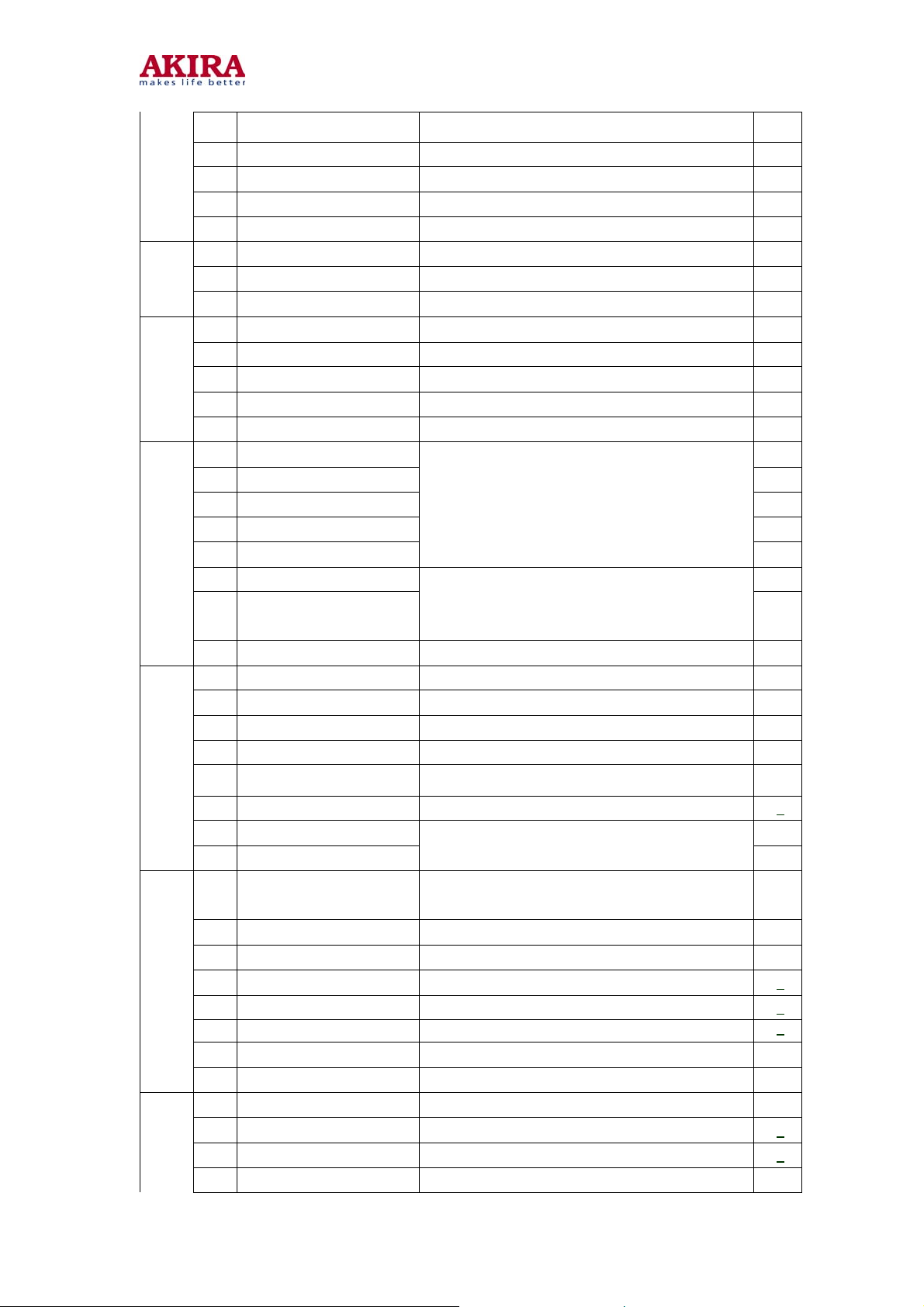
Table 4
HOTEL model,1:yes;0:no 1
CHANNEL number setup(1:236,0:100) 1
NTSC (1:yes,0:no) 1
2 AV input(1:AV2,0:no AV2) 1
V L ( : 1 y e s ; 0 : n o AVL (SLIM CRT)) 1
Text language setupOP_NOT_3/2/1 ,
text
1XX-English/ Arabic
01 1-English /Farsi
010-English /Russian
00 1-English /Ukrainian
000-English / Paneuro
20
0
OP3
OP4
OP5
5 OP_USER_LOGO USER’S LOGO SETUP 0
6 OP_ON_BLACK 1:blue back;0:black back 0
7 OP_FSL 0
0 OP_ENGLISH OSD language: 1,ENGLISH 1
1 OP_CZECH OSD language: 1, CZECH 1
2 OP_SLOVAK OSD language: 1, SLOVAK 1
3 OP_RUSSIAN OSD language: 1, RUSSIAN 1
4
OP_FRENCH OSD language: 1, FRENCH 1
5 OP_GERMAN OSD language: 1, GERMAN 1
6 OP_ITALY OSD language: 1, ITALY 1
7 OP_SPANISH OSD language: 1, SPANISH 1
0 OP_PORTUGUESE OSD language: 1, PORTUGUESE 1
1 OP_SERBIAN OSD language: 1, SERBIAN 1
2 OP_TURKISH OSD language: 1, TURKISH 1
3 OP_POLISH OSD language: 1, POLISH 1
4
OP_BULGARIAN OSD language: 1, BULGARIAN 1
5 OP_ROMANIAN OSD language: 1, ROMANIAN 1
6 OP_CROATIAN OSD language: 1, CROATIAN 1
7 OP_HUNGARIAN OSD language: 1, HUNGARIAN 1
0 OP_UKRAIN OSD language: 1, Ukrainian 1
1 OP_ARABIC OSD language: 1, ARABIC 1
2 OP_FARSI OSD language: 1, FARSI 1
Model no.:CT-21CQS5CPT.doc
version 1.0
Page 21
OP6
OP7
3 OP_BLANK BLANK 0
4 OP_BLANK BLANK 0
5 OP_RFTOAV 1 : S C A R T 0 : RCA 1
6 OP_TDA1517 1 : T D A 1 5 1 7 ; 0 : TFA9842AJ 0
7 OP_FAKE_AVL 1:FAKE A V L ; 0 : A V L 0
0 OP_AV_ON 1:AV shutdown,AV r e s t a r t ; 0 : T V restart 1
1 OP_DIRECT_SWITCH 1:memory-restart;0:power-on and standby 1
2 OP_HCO EHT tracking mode 0
3 OP_CHH_LOGO 1:CHANGHONG l ogo 0
4 OP_SOUND_DK 1:D/K 1
5 OP_SOUND_BG 1:B/G 1
6 OP_SOUND_I 1:I 1
7 OP_SOUND_M 1:M 1
0 OP_AUTO_LANGO 0
1 OP_AUTO_LANG 1 0
2 OP_AUTO_LANG2 0
3 OP_AUTO_LANG3 0
4 OP_AUTO_LANG4
5 OP_FORF 1
6 OP_FORS
AUTO_ Language 4/3/2/1/0:
ENGLISH:00000
CZECH:00001
SLOVAK:00010
…
OP_FORS/FORF:
00-AUTO 60HZ,01-KEEP LAST,
10-FORCE 60HZ,11-AUTO 50HZ
21
0
1
OP8
OP9
OP10
7 OP_HOTEL_ON_PROG 1 :Startup on channel 1 hotel model available0
0 OP_AUTO_TEST Power-on self-test , 1 :yes,0,no 0
1 OP_PSNS sensibility 0
2 OP_B SCREEN Black screen1 Yes;0:No 0
3 OP_SECAM 1:SECAM 1
4
OP_DFL Disable flash protection 1
5 OP_SIF 0
6 OP_EXT_SIF0 1
7 OP_EXT_SIF1
0 OP-TUNER
1 OP_TINT 1 :PAL TINT Adjust 1
2 OP_FMWS WINDOW OF SOUND PLL:+/-200KHZ 1
3 OP_FMWS1 WINDOW OF SOUND PLL:+/-600KHZ 0
4 OP_OSVE 0
5 OP-FFI 0
6 OP-SPEED 1 Program quickly, 1:yes,0no 0
7 OP-SPEED0 Program slowly, 1:yes,0no 0
0 OP_AKIRA_LOGO LOGO:AKIRA 0
1 OP_HBL 0
2 OP_NTSC_TUNER 1:TAF5-U2F22 0
3 OP_CHILD_LOCK 1 :CHILD LOCK 0
D/K:00,B/G:01,I:10,M:11.
0:TAF5-E4I22
1:TAF5-C4I21/ TAF5-C4I23
0
0
Model no.:CT-21CQS5CPT.doc
version 1.0
Page 22
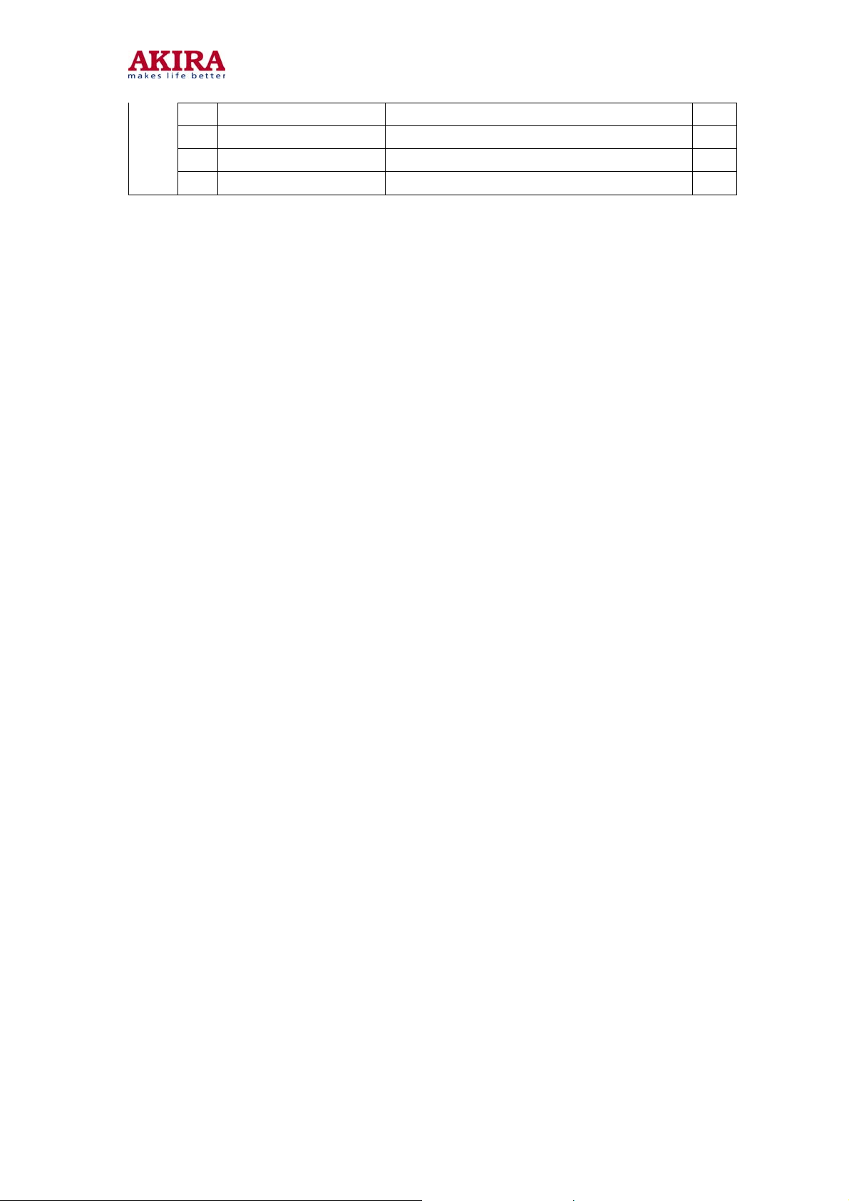
Notes: The data sheet may differ dependent on different models.
The data sheet may differ dependent on different CRTs for the same model.
4 OP_BLANK BLANK 0
5 OP_BLANK BLANK 0
6 OP_BLANK BLANK 0
7 OP_TEXT_KEY 1: (remote-control unit)TEXT key available 1
22
Model no.:CT-21CQS5CPT.doc
version 1.0
Page 23
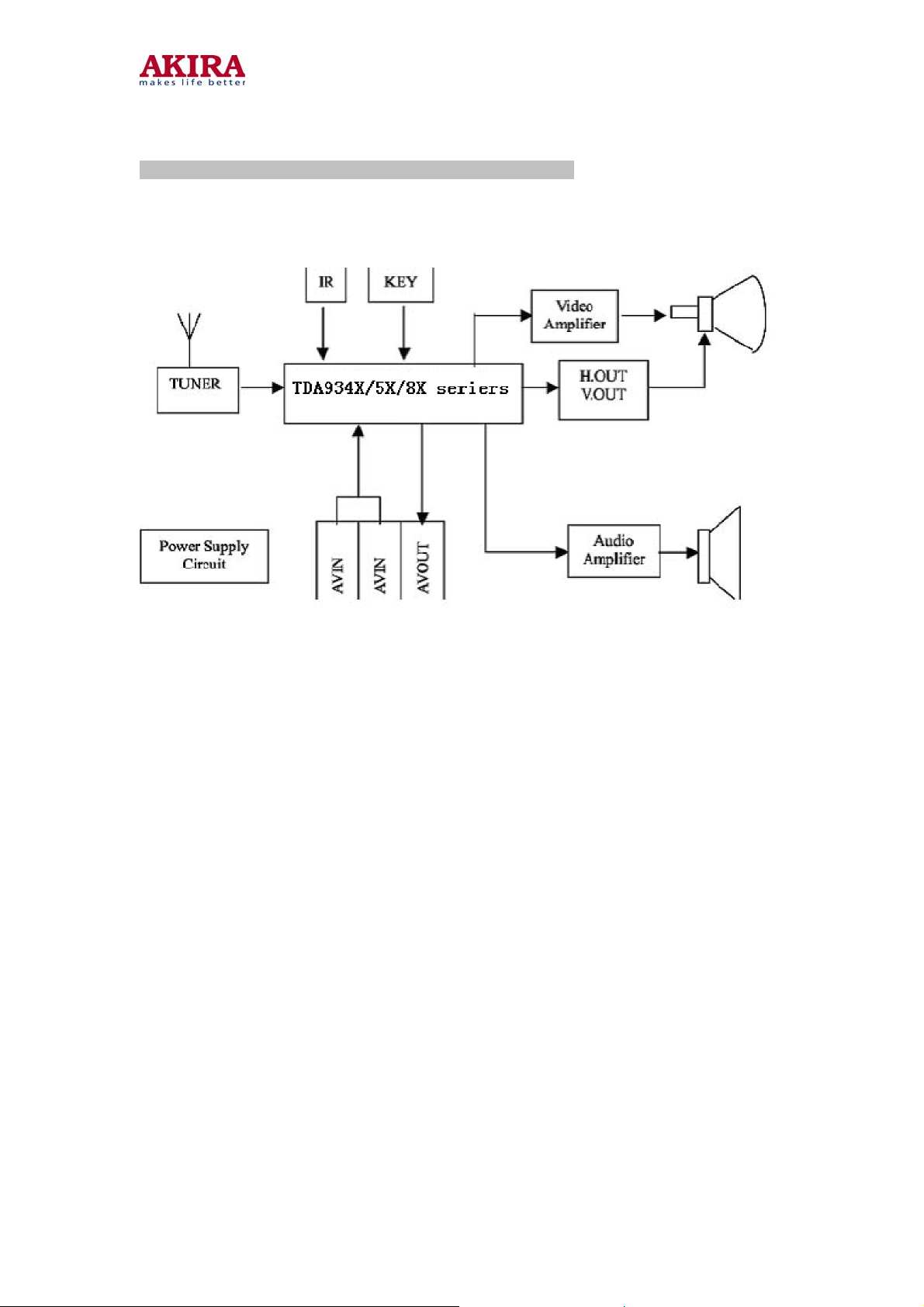
STRUCTURE AND CHASSIS FUNCTION DESCRIPTION
1.STRUCTUE BLOCK DIAGRAM
23
2 CHASSIS DESCRIPTION
2.1 General Description
ETE-2 chassis is applied in PF21GB300 seriers. By use of philips UOC for TV small signal
processing and bus control, the chassis enables TV tuning, adjustment, control and picture
correction, featuring high-integration, high-performance-to-price ratio and high-reliability
and compact circuit with fewer external components. The chassis, widely used in small and
medium TVs, provides much more convenience for manufacturing and technical service. It
includes:
UOC TDA9384PS/N3/3 for PAL/NTSC /SECAM small signal processing and bus control
EEPROM AT24C08 for data memory TDA4863AJ for vertical output power amplifying
TFA9842AJ for audio power amplifying Thick-film IC STR-G5653 for power circuit
adjustment and control.
2.2 The following features are available in the
chassis: Color systems: PAL, NTSC
Sound systems: D/K, B/G, I , M
236 programs preset
AV stereo
IIC bus control Electronic
Hotel
Biorhythm
Model no.:CT-21CQS5CPT.doc
version 1.0
Page 24
(
)
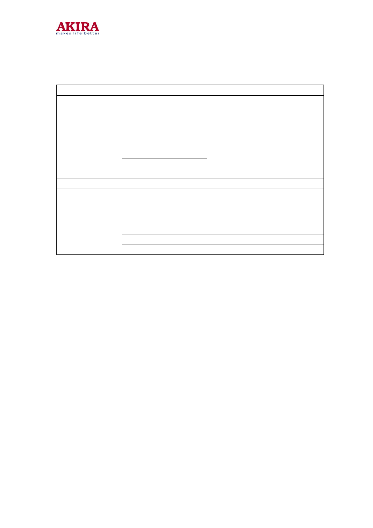
2.3 The chassis mainly uses the follow ing ICs and assemblies.
1 N200 AT24C08 EERPOM
2 N100
Position Type Description
TDA9384PS/N3/3
(slim C R T n o
TDA9353PS/N3/3
(Small signal processor + micro
control
unit (MCU)) TEXT)
24
TDA938
1PS/N3/3
TDA9345PS/N3/3
(1 page TEXT)
3 N601 TFA9842AJ Audio power amplifier
4 N300
5 N801 STR-G5653 Switch-mode power supply control
6 A001
TDA4863AJ
TDA4864AJ
TAF5-C4I21/
TAF5-C4I23
TAF5-E4I22 IF 38.9MHz tuner
TAF5-U2F22 IF 45.75MHz tuner
noTEXT
(slim C R T 1
Vertical scan output stage circuit
IF 38MHz tuner
page TEXT)
slim CRT
Model no.:CT-21CQS5CPT.doc
version 1.0
Page 25

25
SERVICE DATA
1 TV signal processor TDA935X/8X PS-N3 series
1.1 GENERAL DESCRIPTION
The various versions of the TDA935X/8X/ PS-N3 series combine the functions of a video
processor together with a -Controller and US Closed Caption decoder. Most versions have
a Teletext decoder on board. The Teletext decoder has an internal RAM memory for 1 or 10
page text. The ICs are intended to be used in economy television receivers with 90and 1
10picture tubes. The ICs have supply voltages of 8 V and 3.3 V and they are mounted in an
SDIP-64 envelope.
The features are given in the following feature list.
1.2 FEATURES TV processor
Available in TDA935X/6X/8X PS versions
·Multi-standard vision IF circuit with alignment-free PLL demodulator
·Internal (switchable) time-constant for the IF-AGC circuit
·The mono intercarrier sound circuit has a selective FM-PLL demodulator which can be
switched to the different FM sound frequencies (4.5/5.5/6.0/6.5 MHz). The quality of this
system is such that the external band-pass filters can be omitted.
·The FM-PLL demodulator can be set to centre frequencies of 4.74/5.74 MHz so that a
second sound channel can be demodulated. In such an application it is necessary that an
external band pass filter is inserted.
·Integrated chrominance trap circuit
·Integrated luminance delay line with adjustable delay time
·Picture improvement features with peaking (with switchable centre frequency, depeaking,
variable positive/negative overshoot ratio and video dependent coring) and blue- and black
stretching. All features are available for CVBS, Y/C and YPBPR signals.
·Tint control for external RGB/YPBPR signals
·Integrated chroma band-pass filter with switchable centre frequency
·Only one reference (12 MHz) crystal required for the -Controller, Teletext- and the colour
decoder
·Multi-standard colour decoder with automatic search system
·Internal base-band delay line
·Indication of the Signal-to-Noise ratio of the incoming CVBS signal
·A linear RGB/YUV/YPBPR input with fast blanking for external RGB/YUV sources. The
synchronisation circuit can be connected to the incoming Y signal. The Text/OSD signals
are internally supplied from the -Controller/Teletext decoder.
·RGB control circuit with ‘Continuous Cathode Calibration’, white point and black level
off-set adjustment so that the colour temperature of the dark and the light parts of the
screen can be chosen independently.
2 levels of contrast reduction of main picture possible during OSD/Text insertion (‘halftone’)
·OSD/Text gain reduction control
·Adjustable ‘wide blanking’ of the RGB outputs
·Horizontal synchronization with two control loops and alignment-free horizontal oscillator
·Vertical count-down circuit
·Vertical driver optimized for DC-coupled vertical output stages
·Horizontal and vertical geometry processing
Model no.:CT-21CQS5CPT.doc
version 1.0
Page 26

26
·Horizontal and vertical zoom function for 16: 9 applications
·Horizontal parallelogram and bow correction for large screen picture tubes
·Low-power start-up of the horizontal drive circuit
·Macrovision keying possibility for horizontal synchronisation.
Available in TDA935X/6X/8X PS versions
·A choice can be made between versions with mono intercarrier sound FM demodulator and
versions with QSS IF amplifier.
·Source selection between the ‘internal’ CVBS and an external CVBS or Y/C signal
Controller
·80C5 1 -controller core standard instruction set and timing
·1 s machine cycle
·32 - 128Kx8-bit late programmed ROM
·3 - 12Kx8-bit Auxiliary RAM (shared with Display)
·Interrupt controller for individual enable/disable with two level priority
·Two 16-bit Timer/Counter registers
·One 16-bit Timer with 8-bit P re-scaler
·WatchDog timer
·Auxiliary RAM page pointer
·16-bit Data pointer
·Stand-by, Idle and Power Down modes
·14 bits PWM for Voltage Synthesis Tuning
·8-bit A/D converter
·4 multiplexed inputs for the A/D converter and 5 PWM (6-bits) outputs for control of TV
analogue signals (TDA95XX series)
·4 pins which can be programmed as general I/O pin, ADC input or PWM (6-bit) output
(TDA93XX series)
Data Capture
• Text memory for 1 or 10 pages
• In the 10 page versions inventory of transmitted Teletext pages stored in the
Transmitted Page Table (TPT) and Subtitle Page Table (SPT)
• Data Capture for US Closed Caption
• Data Capture for 525/625 line WST, VPS (PDC system A) and Wide Screen Signalling
(WSS) bit decoding
• Automatic selection between 525 WST/625 WST
• Automatic selection between 625 WST/VPS on line 16 of VBI
• Real-time capture and decoding for WST Teletext in Hardware, to enable optimized
processor throughput
• Real-time packet 26 engine in Hardware for processing accented, G2 and G3
characters
• Signal quality detector for video and WST/VPS data types
• Comprehensive teletext language coverage
Full Field and Vertical Blanking Interval (VBI) data capture of WST data
Model no.:CT-21CQS5CPT.doc
version 1.0
Page 27
Display
• Teletext and Enhanced OSD modes
• Features of level 1.5 WST and US Close Caption
• Serial and Parallel Display Attributes
• Single/Double/Quadruple Width and Height for characters
• Scrolling of display region
• Variable flash rate controlled by software
• Enhanced display features including overlining, underlining and italics
• Soft colours using CLUT with 4096 colour palette
• Globally selectable scan lines per row (9/10/13/16) and character matrix [12x10,
12x13, 12x16 (VxH)]
• Fringing (Shadow) selectable from N-S-E-W direction
• Fringe colour selectable
• Meshing of defined area
• Contrast reduction of defined area
• Cursor
• Special Graphics Characters with two planes, allowing four colours per character
• 32 software redefinable On-Screen display characters
• 4 WST Character sets (G0/G2) in single device (e.g. Latin, Cyrillic, Greek, Arabic)
• G1 Mosaic graphics, Limited G3 Line drawing characters
• WST Character sets and Closed Caption Character set in single
27
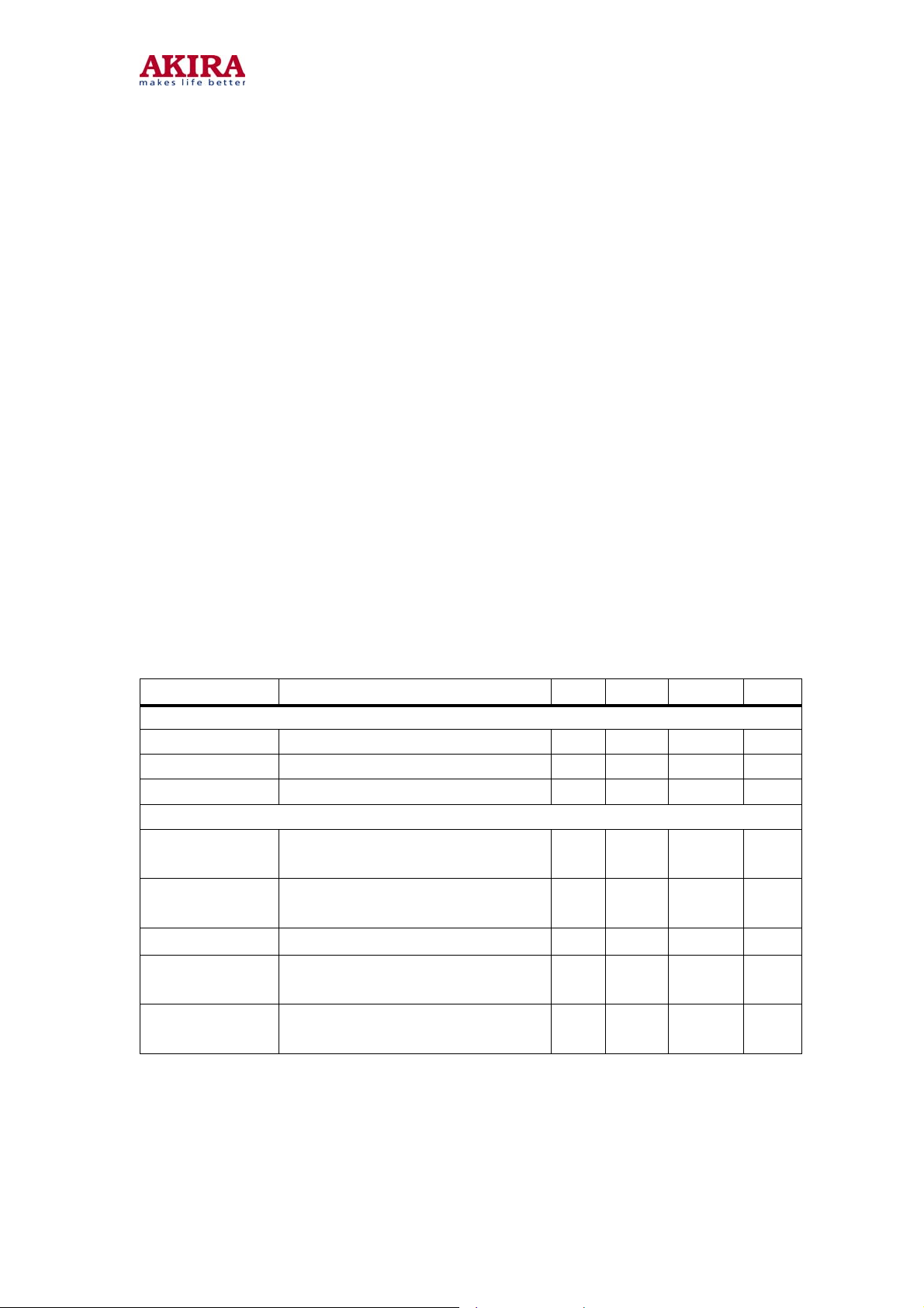
QUICK REFERENCE DATA
SYMBOL PARAMETER MIN. TYP. MAX. UNIT
Supply
Vp supply voltages 8.0/3.3 V
Ip supply current (VP = 8 V) 135 mA
Ip supply current (VP = 3.3 V) 60 mA
Input voltages
ViVIF(rms)
ViSIF(rms)
ViAUDIO(rms) external audio input (RMS value) 500 mV
ViCVBS(p-p)
ViCHROMA(p-p)
video IF amplifier sensitivity (RMS
value)
QSS sound IF amplifier sensitivity
(RMS value)
external CVBS/Y input (peak-to-peak
value)
external chroma input voltage (burst
amplitude)
75 V
45 d B V
1.0 V
0.3
V
Model no.:CT-21CQS5CPT.doc
version 1.0
Page 28
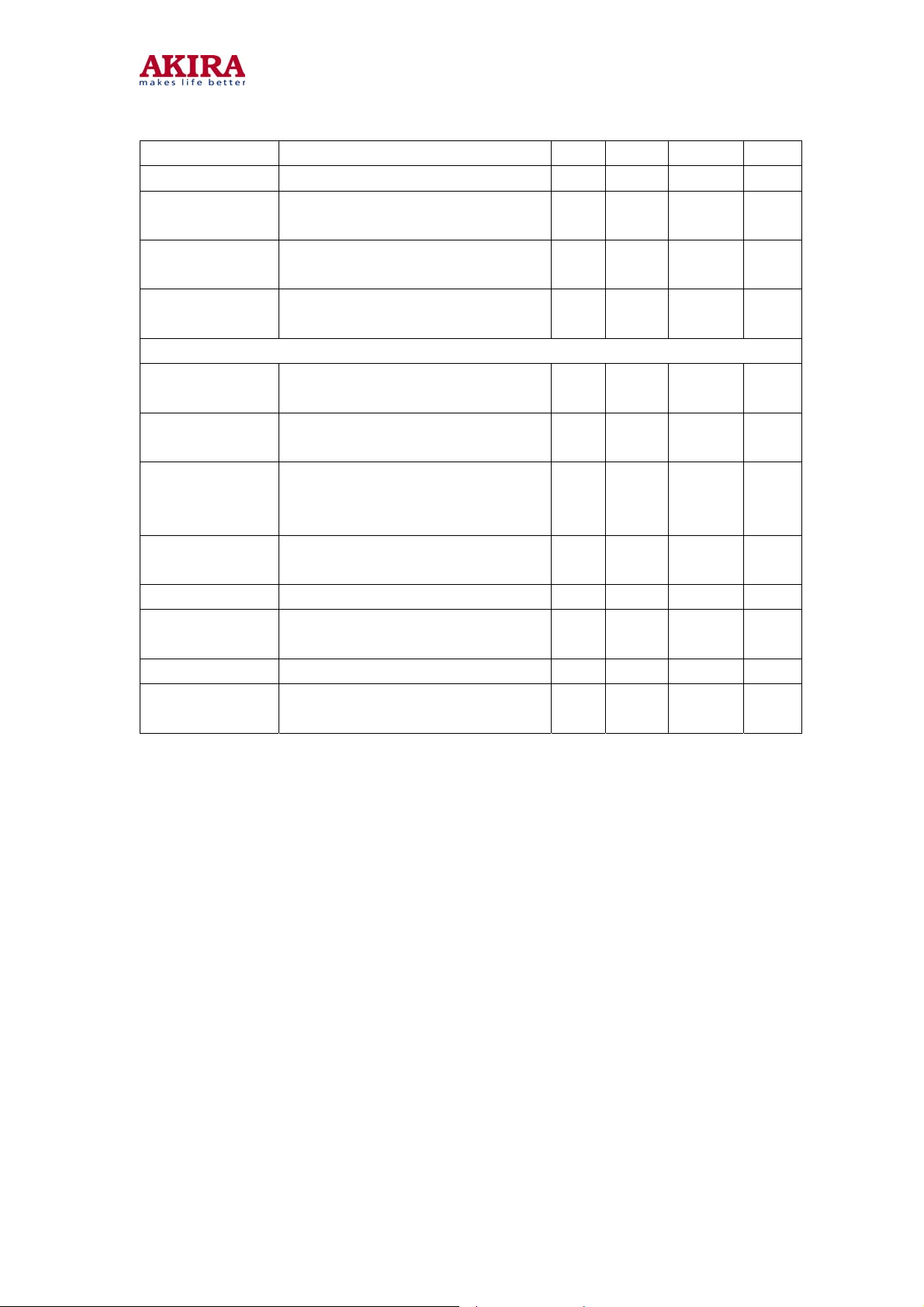
28
(peak-to-peak value)
ViRGB(p-p) RGB inputs (peak-to-peak value) 0.7 V
ViY(p-p)
ViU(p-p) /
ViPB(p-p)
luminance input signal (peak-to-peak
value)
U / PB input signal (peak-to-peak
value)
1.4 /
1.0
1.33 /
+0.7
V
V
ViV(p-p) /
ViPR(p-p)
Output signals
V
o(IFVO)(p-p)
V
o(QSSO)(rms)
V
o(AMOUT)(rms)
V
o(CVBSO)(p-p)
I o(AGCOUT) tuner AGC output current range 0 5 mA
V oRGB(p-p)
I oHOUT horizontal output current 10 mA
I oVERT
V / PR input signal (peak-to-peak
value)
Demodulated CVBS output
(peak-to-peak value)
sound IF intercarrier output in QSS
versions (RMS value)
demodulated AM sound output in
QSS versions (RMS
value)
selected CVBS output (peak-to-peak
value)
RGB output signal amplitudes
(peak-to-peak value)
vertical output current (peak-to-peak
value)
2.0 V
2.0 V
1 mA
1.05 /
+0.7
2.0 V
100 Mv
500
mV
V
Model no.:CT-21CQS5CPT.doc
version 1.0
Page 29
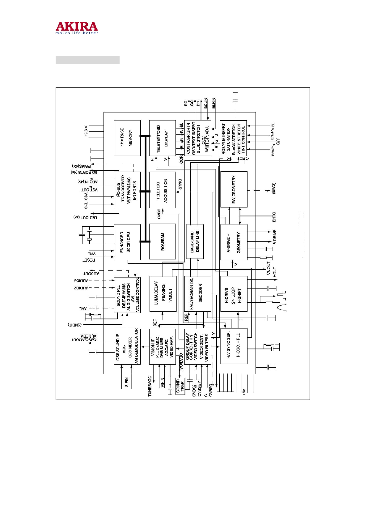
BLOCK DIAGRAM
29
Model no.:CT-21CQS5CPT.doc
version 1.0
Page 30
p
p
p
g
A
I
I
g
A
A
f
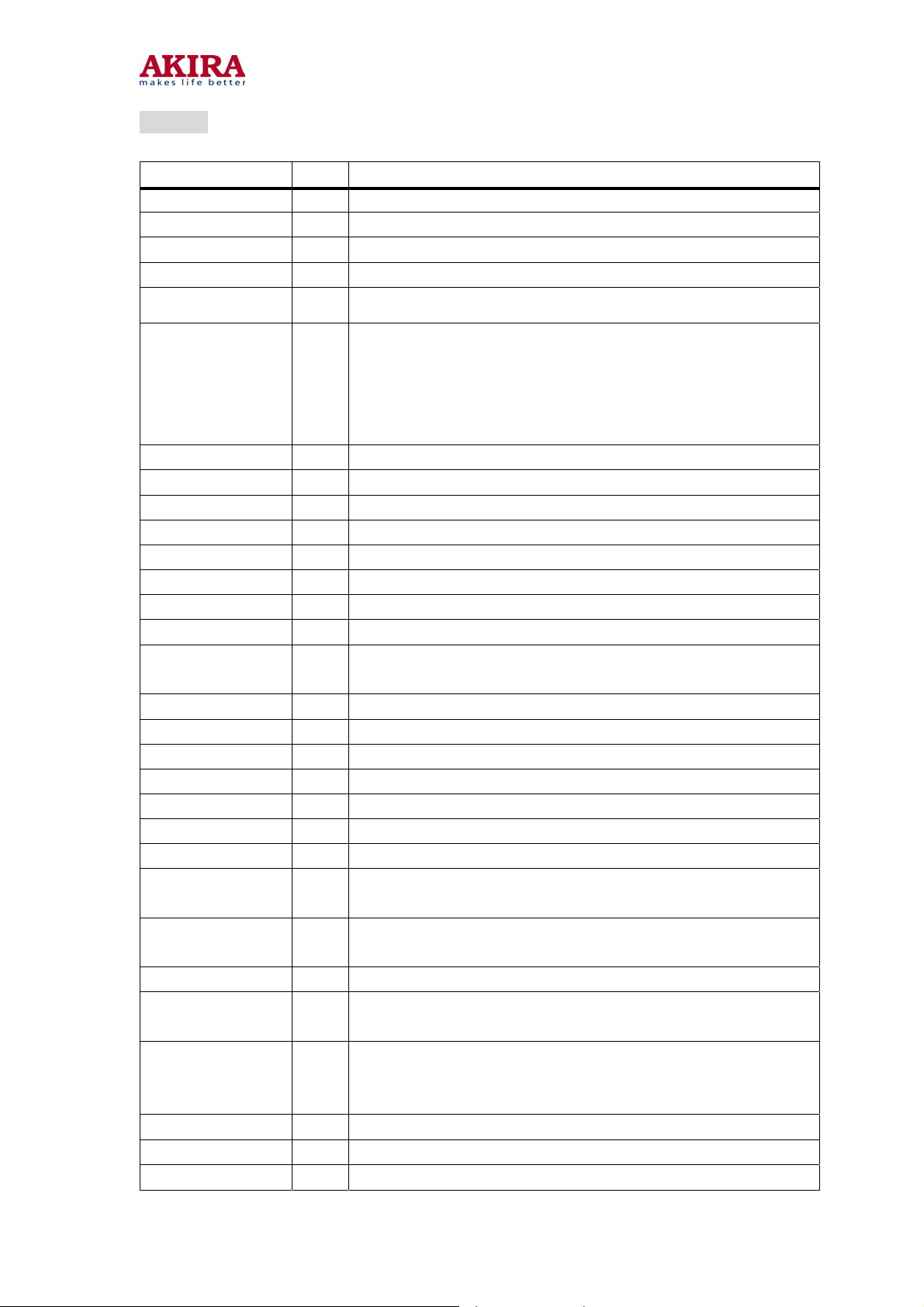
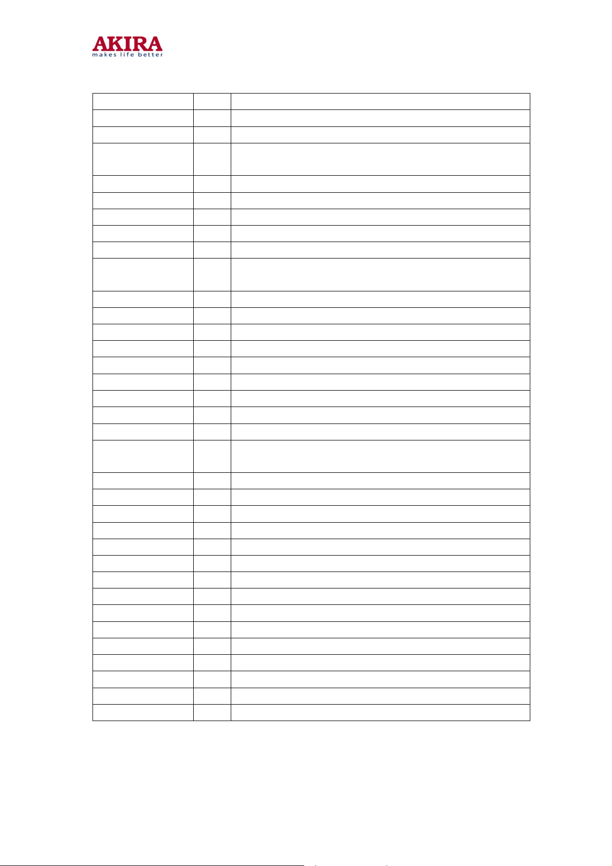
Pinning
SYMBOL PIN DESCRIPTION
P3.1/ADC1/PWM1 6 port 3.1 or ADC1 input or PWM1 output
P3.2/ADC2/PWM2 7 port 3.2 or ADC2 input or PWM2 output
P3.3/ADC3/PWM3 8 port 3.3 or ADC3 input or PWM3 output
VSSC/P 9 digital ground for -Controller core and periphery
30
P0.5 10
P0.6/C VBSTD 11
VSSA 12 digital ground of TV-processor
SECPLL 13 SE CAM PLL decoupling
VP2 14 2nd supply voltage TV-processor (+8V)
DECDIG 15 supply voltage decoupling of digital circuit of TV-processor
PH2LF 16
PH1LF 17
GND3 18
DECBG 19 bandgap decoupling
AVL/EWD (1)
VDRB 21 vertical drive B output
VDRA 22 vertical drive A output
IFIN1 23
IFIN2 24
IREF 25 reference current input
VSC 26 vertical sawtooth capacitor
AGCOUT 27 tuner AGC output
ort 0.5 (8 mA current sinking capability for direct drive of LEDs)
port 0.6 (8 mA current sinking capability for direct drive of
LEDs)
or
Composite video input. A positive-going 1 V(peak-to-peak)
input is required
hase-2 filter
hase-1 filter
round 3 for TV-processor
utomatic Volume Levelling (90versions)/ E-W drive output
20
(110versions)
F input 1
F input 2
SIFIN1/A UDEEM
(2)
SIFIN2/DECSDEM
(2)
GND2 30
SNDPLL/SIFA GC
(2)
AVL/REF0/SNDIF/
AMOUT (2)
HOUT 33 horizontal output
FBISO 34
QSSO/AMOUT/ 35 QSS intercarrier output / AM output / external audio input
Model no.:CT-21CQS5CPT.doc
version 1.0
SIF input 1 / audio deemphasis
28
SIF input 2 / decoupling sound demodulator
29
round 2 for TV processor
31 narrow band PLL / AGC sound IF
32
utomatic Volume Levelling / subcarrier reference output /
sound IF input /
M output
lyback input/sandcastle output
Page 31
A UDEXT
EHTO 36 EHT/overvoltage protection input
PLLIF 37 IF-PLL loop filter
(2)
31
IFVO/SVO/DVBO
(2)
VP1 39 main supply voltage TV processor
CVBS1 40 internal CVBS input
GND 41 ground for TV processor
CVBS3/Y 42 CVBS3/Y input
C 43 chroma input
AUDOUT /
AMOUT (2)
INSSW2 45 2nd RGB / YUV insertion input
R2/V/PR-IN 46 2nd R input / V (R-Y) input / PR input
G2/Y-IN 47 2nd G input / Y input
B2/U/PB -IN 48 2nd B input / U (B-Y) input / PB input
BCLIN 49 beam current limiter input
BLKIN 50 b lack current input / V-guard input
RO 51 Red output
GO 52 Green output
BO 53 Blue output
VDDA 54
38
44
IF video output / selected CVBS output / DVB output
(QFP-80)
audio output / AM audio output (volume controlled)
analog supply of Teletext decoder and digital supply of
TV-processor (3.3 V)
VPE 55 OTP Programming Voltage
VDDC 56 digital supply to core (3.3 V)
OSCGND 57 oscillator ground supply
XTALIN 58 crystal oscillator input
XTALOUT 59 crystal oscillator output
RESET 60 reset
VDDP 61 digital supply to periphery (+3.3 V)
P1.0/INT1 62 port 1.0 or external interrupt 1 input
P1.1/T0 63 port 1.1 or Counter/Timer 0 input
P1 .2/INT0 64 port 1.2 or external interrupt 0 input
P1 .3/T1 1 port 1.3 or Counter/Timer 1 input
P1 .6/SCL 2 port 1.6 or I2C-bus clock line
P1 .7/SDA 3 port 1.7 or I2C-bus data line
P2.0/TPWM 4 port 2.0 or Tuning PWM output
P3.0/ADC0/PWM0 5 port 3.0 or ADC0 input or PWM0 output
Model no.:CT-21CQS5CPT.doc
version 1.0
Page 32
32
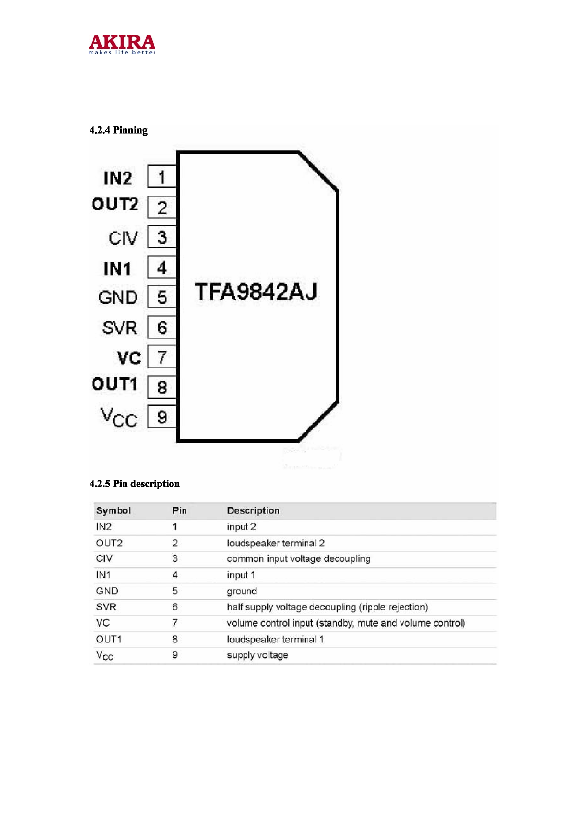
2 TFA9842AJ
2-channel audio amplifier with volume control (SE: 1 W to 7.5 W)
2.1 General description
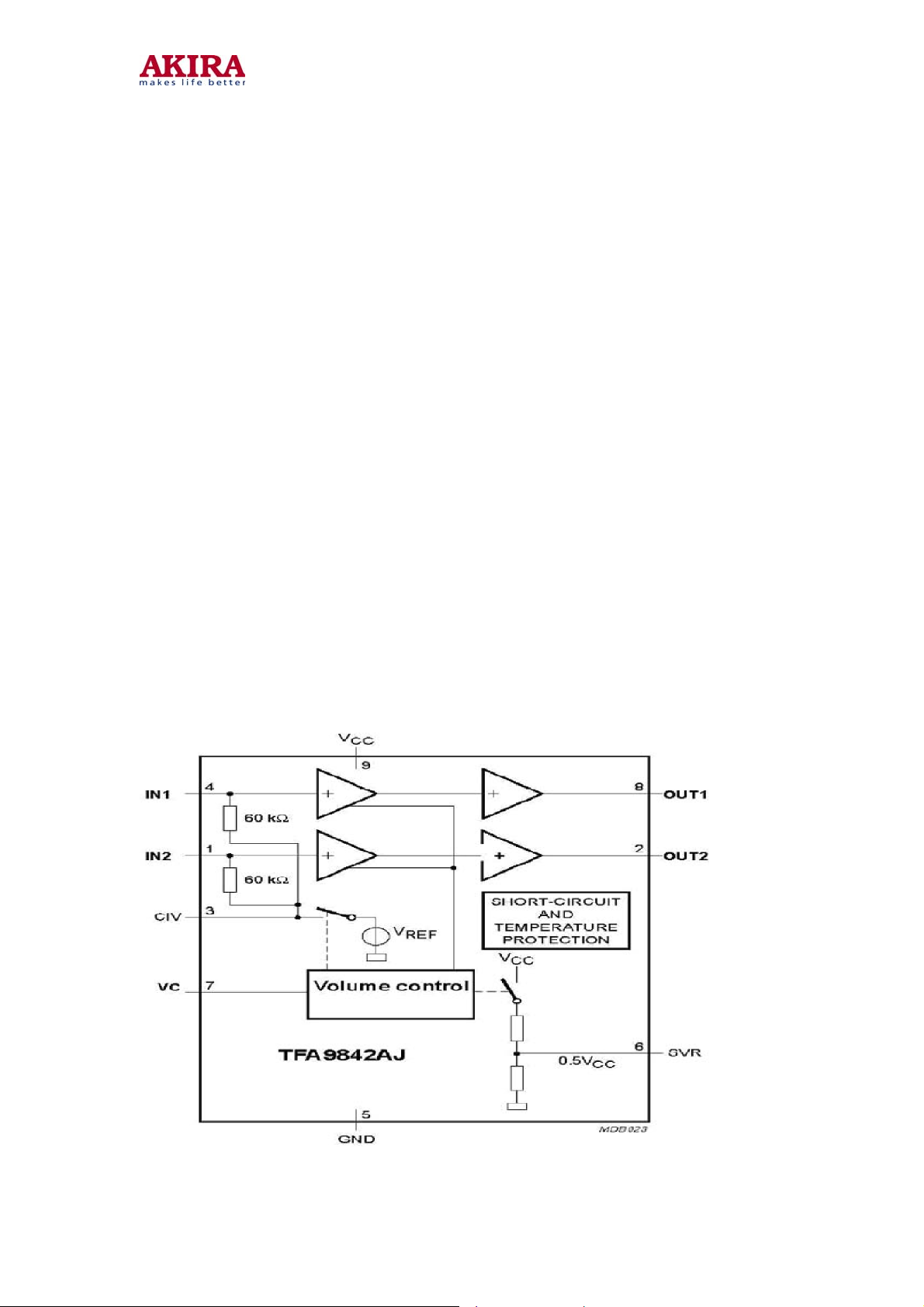
The TFA9842AJ contains two identical audio power amplifiers. The TFA9842AJ can be
used as two Single-Ended (SE) channels with a volume control. The maximum gain is 26 dB.
The TFA9842AJ comes in a 9-pin DIL-bent-SIL (DBS9P) power package. The TFA9842AJ
contains a unique protection circuit that is solely based on multiple temperature
measurements inside the chip. This gives maximum output power for all supply voltages
and load conditions with no unnecessary audio holes. Almost any supply voltage and load
impedance combination can be made as long as thermal boundary conditions (number of
channels used, external heatsink and ambient temperature) allow it.
2.2 Features
2 Channel SE: 1 W to 7.5 W operation possibility
Soft clipping
Input clamps
Volume control
Standby and mute mode
No on/off switching plops
Low standby current
High supply voltage ripple rejection
Outputs short-circuit protected to ground, supply and across the load
Thermally protected
2.3 Block diagram of TFA9842AJ
Model no.:CT-21CQS5CPT.doc
version 1.0
Page 33
33
Model no.:CT-21CQS5CPT.doc
version 1.0
Page 34
3 VERTICAL SCAN OUTPUT STAGE CIRCUIT
TDA4863AJ/TDA4864A J
4.3.1 FEATURES
TDA4863AJ:Output current up to 3 A (p-p)
TDA4864AJ: Output current up to 2.5A (p-p)
3.2 GENERAL DESCRIPTION
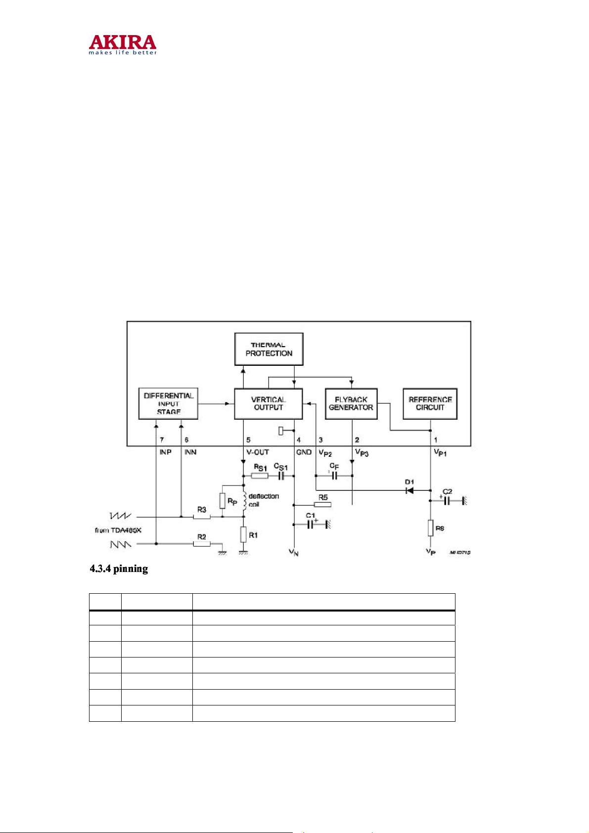
The TDA4863AJ and TDA4864AJ are deflection boosters for use in vertical deflection
systems for frame frequencies up to 200 Hz.
The TDA4863AJ or TDA4864AJ needs a separate flyback supply voltage, so the supply
voltages are independently adjustable to optimize power consumption and flyback time.
For the TDA4863AJ or TA4864AJ the flyback supply voltage will be generated internally
by doubling the supply voltage and therefore a separate flyback supply voltage is not
needed.
3.3 Block diagram of TDA4863AJ and TDA4864AJ
34
PIN SYMBOL DESCRIPTION
1 VP1 positive supply voltage 1
2 VP3 flyback generator output
3 VP2 supply voltage 2 for vertical output
4 GND ground or negative supply voltage
5 V-OUT vertical output
6 INN inverted input of differential input stage
7 INP non-inverted input of differential input stage
Model no.:CT-21CQS5CPT.doc
version 1.0
Page 35
35
4 EEPROM AT24C08
4.1 Features
Data EEPROM internally organized as 1024/2048 bytes and 64/128 pages×16 bytes
Page protection mode, flexible page-by-page hardware write protection -Additional
protection EEPROM of 64/128 bits, bit per data page 1-Protection setting for each data
page by writing its protection bit -Protection management without switching WP pin
Low power CMOS
Vcc=2.7 to 5.5V operation
Two wire serial interface bus, IIC-Bus compatible
Filtered inputs for noise suppression with Schmitt trigger
Clock frequency up to 400 kHz
High programming flexibility
− Internal programming voltage
− Self timed programming cycle including erase
− Byte-write and page-write programming, between 1 and 16 bytes
− Typical programming time 6ms(< 1 0ms) for up to 16 bytes
High reliability
− Endurance 106 cycles 1)
− Data retention 40 years 1)
− ESD protection 4000 V on all pins
8 pin DIP/DSO packages
Available for extended temperature ranges
− Industrial: - 4 0 to +85
− Automotive: - 4 0 t o +125
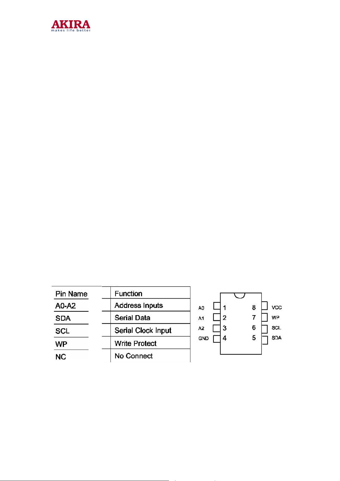
4.2 Pin Configuration
4.3 Pin Description
SERIAL CLOCK (SCL): The SCL input is used to positive edge clock data into each
EEPROM device and negative edge clock data out of each device.
SERIAL DATA (SDA): The SDA pin is bi-directional for serial data transfer. This pin is
open-drain driven and may be wire-ORed with any number of other open-drain or
open-collector devices. The AT24C08 only uses the A2 input for hardwire addressing and a
total of two 8K devices may be addressed on a single bus system. The A0 and A1 pins are
no connects.
Model no.:CT-21CQS5CPT.doc
version 1.0
Page 36
36
4.4 Memory Organization
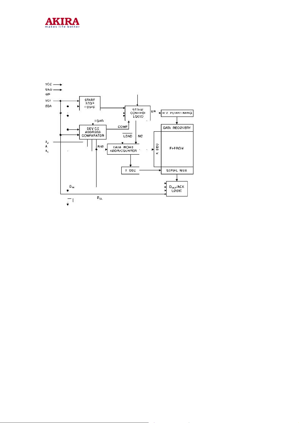
AT24C08, 8K SERIAL EEPROM: Internally organized with 64 pages of 16 bytes each, the
8K requires a 10-bit data word address for random word addressing.
4.4.5 Block Diagram
Model no.:CT-21CQS5CPT.doc
version 1.0
Page 37
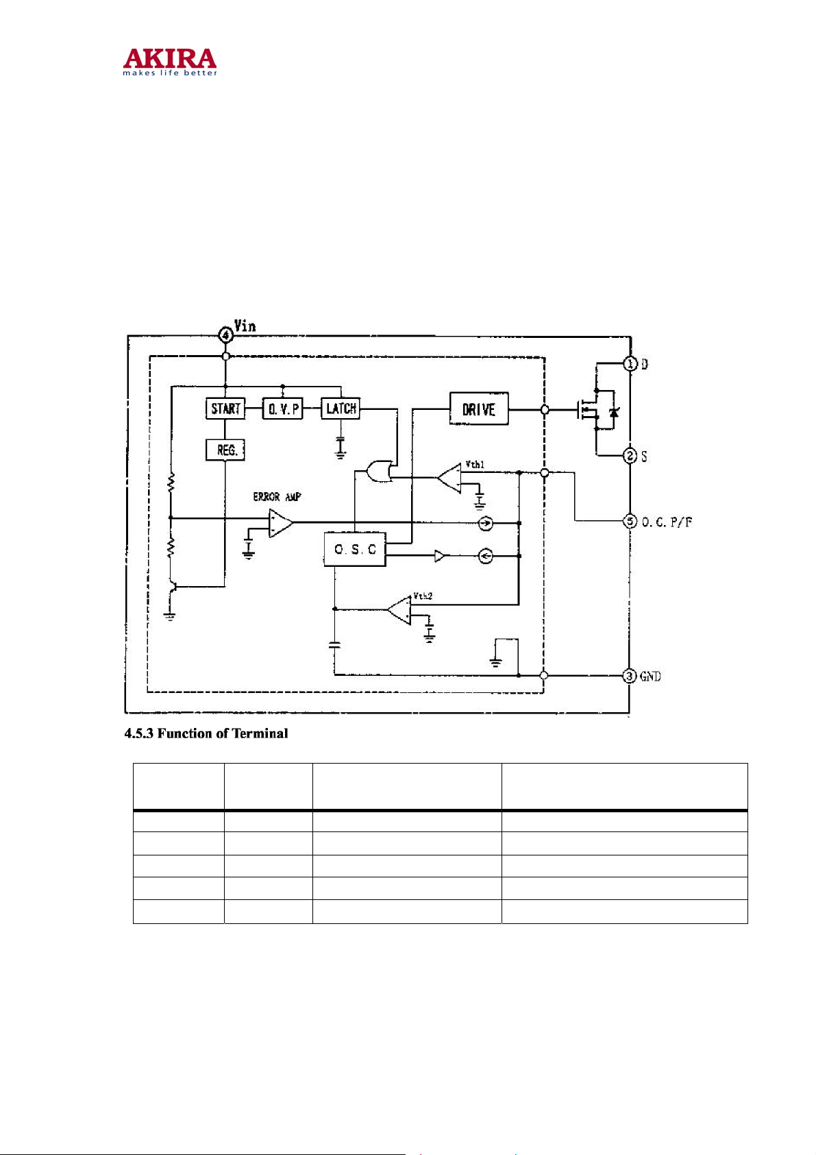
5 SWITCH-MODE POWER SUPPLY IC STRG5653
5.1 General Description
The STRG5653 is part of the STRG5600 series thick-film ICs for switch-mode
power supply incorporating power MOSFET with a high-precise error amplifier.
The ICs feature fewer external components, small-size and standard power
supply.
5.2 Block Diagram
37
Terminal
No.
1 D Drain Terminal MOS FET drain
2 S Source Terminal MOS FET source
3 GND Ground Terminal Ground
4 VIN Power supply Terminal Input of power supply for control
5 O.C.P/F.B Over current/Feedback Input of over current detection signal
Symbols Description
Functions
Model no.:CT-21CQS5CPT.doc
version 1.0
Page 38
38
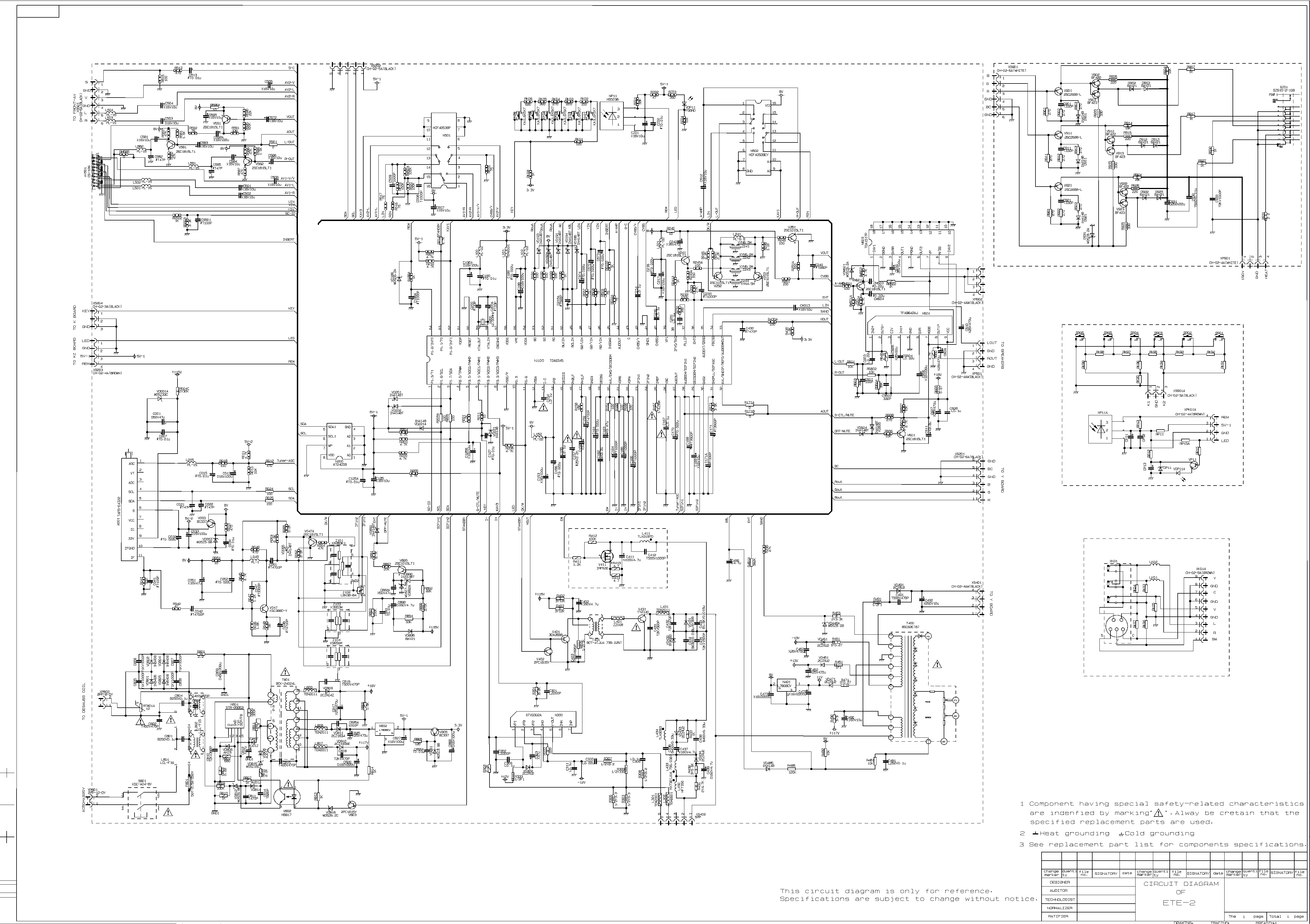
APPENDIX
Model no.:CT-21CQS5CPT.doc
version 1.0
Page 39
Page 40

40
REPLACEMENT PARTS LIST
PART CODE DESCRIPTION SPECIFICATION QTY LOCATION
54111A04180 POWER SWITCH KDC-A04-MU171 1
54111A04180 POWER SWITCH KDC-A04(30)
54111A04180 POWER SWITCH PS5E-A-T1
56231310080 SPEAKER YDT313-A3-10W-8 2
8475901360B DEGAUSSING COIL XC-14E9 1
681C14C1BM2 14" CRT A34JQQ90X94 1
FRONT PANEL 1
883370040G007 POWER KNOB JUC8.337.040-G007 1
883370139G007 FUNCTION KEY JUC8.337.139-G007 1
886400710C LENS JUC8.640.071 1
50990011560 REMOTE CONTROLLER GK22B1-C11 1
8782000110G MAIN PCB JUG7.820.011 1
50820012670 CHIP RES. RC-05K000JT 6 RM607A J002 J003 J005 RS503
RS101
50820012680 CHIP RES. RC-05K100JT 2 R211 R051
51905470JW5 CHIP RES. RC-05K470JT 1 R042
50820014550 CHIP RES. RC-05K560JT 1 R048
50820012970 CHIP RES. RC-05K750JT 8 R507 R508 R509 R517 R592
R521 R522 R041
50820012690 CHIP RES. RC-05K101JT 9 R015 R191 R192 R193 R245A
R249 R251 R251A R430A
50820012750 CHIP RES. RC-05K151JT 1 R243A
50820012860 CHIP RES. RC-05K331JT 1 R591
50820012890 CHIP RES. RC-05K391JT 1 R231
50820012910 CHIP RES. RC-05K471JT 2 R010 R049
50820012700 CHIP RES. RC-05K102JT 2 R241A RK08
50820012650 CHIP RES. RC-05K122JT 2 R047 R248
50820012790 CHIP RES. RC-05K182JT 1 R046
50820012810 CHIP RES. RC-05K222JT 2 R062 R065
50820012840 CHIP RES. RC-05K272JT 1 R171
50820012920 CHIP RES. RC-05K472JT 15 R011 R045 R203 R204 R205
R220 R891 R582 R583 R584
R587 R588 R589 R581 R586
50820014560 CHIP RES. RC-05K682JT 1 R063
51905103JW5 CHIP RES. RC-05K103JT 2 R195 R606
50820012770 CHIP RES. RC-05K153JT 1 R158
50820012850 CHIP RES. RC-05K273JT 2 R233 R235
51905104JW5 CHIP RES. RC-05K104JT 5 R232 R519 R520 R595 RS100
50810012400 CHIP CAP. 0805CG330J500NT 2 C200 C200A
50810012410 CHIP CAP. 0805CG470J500NT 2 C582 C585
50810012430 CHIP CAP. 0805CG561J500NT 1 C215A
52A72680J04 CHIP CAP. 0805CG681J500NT 1 C240
50810012440 CHIP CAP. 0805CG821J500NT 1 C171A
50810013650 CHIP CAP. 0805CG102J500NT 7 C165
50810012330 CHIP CAP. 0805B102K500NT C166 C186A C233 C430 C508
C509
50810012340 C 0805B222K500NT 1 C157
50810012550 CHIP RES. 0805B332K500NT 2 C047 C168 C061 C159
50810012370 CHIP RES. 0805B472K500NT 3 C042
50810012220 CHIP RES. 0805B103K500NT 5 C007 C034 C125A C190 C127
52A71392K06 CHIP RES. 0805B392K500NT 1 C171
50810012350 CHIP RES. 0805B223K500NT 7 C052 C156 C161 C170 C374
C570 C573
50810012490 CHIP CAP. 0805B104K500NT 3 C032 C189 C218
617100850W7 CHIP DIODE RLS4148TE-11 12 VD065 VD191 VD192 VD193 VD194
VD195 VD201 VD202 VD221A VD604
VD890 VD892
50680010410 CHIP TRANSISTOR MMBT3906LT1G 2 V251 V890
50680010480 CHIP TRANSISTOR MMBT3904LT1G 5 V241 V581 V591 V601 V582
51113100JU0 CARBON RES. RT13-0.166W-10J 2 R242 R596A
51113101JU0 CARBON RES. RT13-0.166W-100J 5 R024 R025 R186A R205A R206
50620072170 CARBON RES. RT13-0.166W-200J 1 R865
51113471JU0 CARBON RES. RT13-0.166W-470J 1 R012
51113102JU0 CARBON RES. RT13-0.166W-1kJ 2 R813 R814
51113182JU0 CARBON RES. RT13-0.166W-1.8KJ 1 R430
51113472JU0 CARBON RES. RT13-0.166W-4.7KJ 2 R207 R214
51113333JU0 CARBON RES. RT13-0.166W-33KJ 1 R894
50620071780 CARBON RES. RT13-0.166W-39KJ 2 R810 R892
50620071470 CARBON RES. RT13-0.166W-120KJ 1 R485
51113105JU0 CARBON RES. RT13-0.166W-1MJ 1 R481A
50620071220 CARBON RES. RT14-0.25W-100J 2 R165 R166
50620071370 CARBON RES. RT14-0.25W-680J 1 R804
50620071250 CARBON RES. RT14-0.25W-1kJ 1 R807
50620071260 CARBON RES. RT14-0.25W-2.2KJ 3 R301 R302 R812
51124302JT0 CARBON RES. RT14-0.25W-3KJ 1 R866
50620072640 CARBON RES. RT14-0.25W-150KJ 1 R893
50620030800 M. OXIDE FILM RES. RJ14-0.25W-39KG 1 R167
50620101360 OXIDE FILM RES. RY21-0.5W-2.2J 1 R307
Model no.:CT-21CQS5CPT.doc
version 1.0
Page 41

41
PART CODE DESCRIPTION SPECIFICATION QTY LOCATION
50620101430 OXIDE FILM RES. RY21-0.5W-3.3J 1 R811
51315331JK0 OXIDE FILM RES. RY21-0.5W-330J 1 R309
50620101310 OXIDE FILM RES. RY21-0.5W-1KJ 1 R405
50620100960 OXIDE FILM RES. RY21-0.5W-270KJ 1 R896
50620102430 OXIDE FILM RES. RY21-0.5W-820KJ 1 R808
50620102690 OXIDE FILM RES. RY21-2W-0.22J 1 R803
50620103280 OXIDE FILM RES. RY21-2W-240J 1 R310
50620101930 OXIDE FILM RES. RY21-2W-3.3KJ 1 R463
50620101770 OXIDE FILM RES. RY21-2W-15KJ 1 R004C
50620101040 OXIDE FILM RES. RY21-2W-300KJ 1 R806
51318123JF0 OXIDE FILM RES. RY21-3W-12KJ 2 R402 R403
51515P27J70 FUSE RES. RF10-0.5W-0.27J 4 R605 R451 R461 R471
51515010J70 FUSE RES. RF10-0.5W-1J 1 R333
50620050310 FUSE RES. RF10-0.5W-1J 1 R491
51224111493 FUSE RES. RF10-2W-1.5J 1 R490
50620080290 WIRE RES. RXG6-H2-10W-2.2J 1 R801
50620040030 THERMAL RES MZ73-9RM 1 RT801A
50620040120 THERMAL RES PTDCA1BF7R0Q200
52532471K10 CERAMIC CAP. CT1-63V-06C-2B4-470PFK 1 C811
52532821K10 CERAMIC CAP. CT1-63V-06C-2B4-820PFK 1 C814
52532102K10 CERAMIC CAP. CT1-63V-06C-2B4-1000PFK 3 C301 C302 C472A
5253F103Z10 CERAMIC CAP. CT1-63V-08C-2F4-10NFZ 2 C866A C891
52542471KV0 CERAMIC CAP. CT1-500V-06A-2B4-470PFK 3 C491 C816 C825A
52542821KV0 CERAMIC CAP. CT1-500V-08a-2B4-820PFK 1 C403
5254F102M10 CERAMIC CAP. CT81-250VAC-2E4-1000PFM-Y1 4 C815
5254F102M10 CERAMIC CAP. CD85-E2GA102MYHS C815A
50640024110 CERAMIC CAP. CT7-250VAC-2E4-1000PFM-Y1 C802 C803
50640023150 CERAMIC CAP. CT81-1KV-16C-2E4-4700PFZ 4 C805 C806 C807 C808
52592681K30 CERAMIC CAP. CT81-2KV-12C-2B4-680PFK 1 C810
52592471K30 CERAMIC CAP. CT81-2KV-10C-2B4-470PFK 1 C818
52368104J10 MYLAR RES. CL21X-63V-0.1FJ 4 C231 C309 C311 C608
50640013360 MYLAR RES. 2222 366 76104 1 C167
52369104J10 MYLAR RES. ECQV1104JMW
52367224J10 MYLAR RES. CL21X-50V-0.22FJ 5 C154 C155 C214 C216 C333
5236C104J10 MYLAR RES. CL21X-250V-0.1FJ 1 C481
5246Q104KB0 POLYPROPYLENE CAP. CBB62-250VAC-0.1FK 2 C801 C804
526134P7M11 ELECTROLYTIC CAP. CD110X-16V-4.7FM 1 C486
52623010060 ELECTROLYTIC CAP. CD110X-16V-10FM 10 C169 C501 C502 C507 C572
C581 C595 C584 C583 C586
52613470M11 ELECTROLYTIC CAP. CD110X-16V-47FM 3 C242 C051 C125
52613101M11 ELECTROLYTIC CAP. CD110X-16V-100FM 8 C013 C033 C188 C190A C217
C592A C827 C866
52613102M11 ELECTROLYTIC CAP. CD110X-16V-1000FM 1 C153
52613222M11 ELECTROLYTIC CAP. CD110X-16V-2200FM 1 C473
52614471M11 ELECTROLYTIC CAP. CD110X-25V-470FM 3 C452 C462 C825
50640062160 ELECTROLYTIC CAP. CD110X-25V-1000FM 1 C472
52616471M11 ELECTROLYTIC CAP. CD110X-35V-470FM 1 C607
52616102M11 ELECTROLYTIC CAP. CD110X-35V-1000FM 1 C817
52617010MV0 ELECTROLYTIC CAP. CD110X-50V-1FM 1 C158
50640062270 ELECTROLYTIC CAP. CD110X-50V-2.2FM 1 C162
52617470M11 ELECTROLYTIC CAP. CD110X-50V-47FM 4 C001 C303 C812 C882A
50640062010 ELECTROLYTIC CAP. CD110X-160V-4.7FM 2 C402 C890
50640062140 ELECTROLYTIC CAP. CD110X-250V-22FM 1 C492
50640063270 ELECTROLYTIC CAP. CD288-160V-47FM 1 C490
50640062370 ELECTROLYTIC CAP. CD288-160V-220uFM 1 C820
50640062440 ELECTROLYTIC CAP. CD293-450V-330FM 1 C809
50630061100 INDUCTOR LGB0606-1HK 1 L049
50630061210 INDUCTOR LGB0606-6.8HJ 1 L241
50630061070 INDUCTOR LGB0606-10HJ 6 L005 L100 L101 L102 L152
50630061520 INDUCTOR LGA0307-10HJ 4 L501 L502 L581 L582
50630010150 INDUCTOR TEM2011 5 L301 L302 L807 L808 L809
555756106A6 INDUCTOR ZZ008 1 L401
61212039BT5 DIODE W05Z3.9B 1 VD861
61212051BT5 DIODE W05Z5.1B 1 VD816
61212056BT5 DIODE W05Z5.6B 1 VD003
61212062AT5 DIODE W 05Z6.2A 2 VD186 VD221
61212068BT5 DIODE W05Z6.8B 1 VD812
61212082BT5 DIODE W05Z8.2B 2 VD448A VD892A
61212150CT5 DIODE W05Z15C 1 VD815
61118010158 DIODE W05Z33C 1 VD001A
61411075DT0 DIODE 1N4148 1 VD485
61411075DT0 DIODE 2CK75D
617100210T0 DIODE BAV21 1 VD896
611120RU210 DIODE 2CZRU2 4 VD302 VD491 VD811 VD471
61112RU4ZN0 DIODE 2CZRU4Z 3 VD809 VD451 VD461
50660091240 DIODE RG4A 1 VD810
50660091200 DIODE MUR460RLG
614145408N0 DIODE BY254 4 VD801
61414540810 DIODE 1N5408 VD802 VD804 VD805
611001030V0 DIODE AK03 1 VD806
611001110T0 DIODE AU01Z 3 VD807 VD808 VD814
62118150Y16 AUDION 3DG1815-Y 2 V402
50650030770 AUDION 2PC1815Y V803
Model no.:CT-21CQS5CPT.doc
version 1.0
Page 42

42
PART CODE DESCRIPTION SPECIFICATION QTY LOCATION
62118150Y16 AUDION KTC3198-Y
62118150Y16 AUDION 2SC1815-Y
62703370045 AUDION BC337-40 2 V003 V805
621038820T0 AUDION 2SC388ATM 1 V047
62118111296 AUDION KSC388C-Y
621038820T0 AUDION 3DG388ATM
50650030570 AUDION 3DA2688 1 V401
62126880010 AUDION 2SC2688-L
50390020150 PHOTO COUPLE HPC922 1 V802
67109P62116 PHOTO COUPLE HS817
67109S81700 PHOTO COUPLE HS817C
66115615306 I.C SFH615A-3
66110816005 I.C LTV-816
67109P62116 PHOTO COUPLE TCET1106
67109S81700 PHOTO COUPLE TCET1103
50950010440 CRYSTAL OSCILLATOR JA18A-12.000MHZ 1 G200
5741465MB05 CERAMIC TRAP FILTER TPS6.5MB 1 Z241
50570050120 CERAMIC TRAP FILTER XT6.5MB
5741460MB05 CERAMIC TRAP FILTER TPS6.0MB 1 Z242
50570050110 CERAMIC TRAP FILTER XT6.0MB
5741455MB05 CERAMIC TRAP FILTER TPS5.5MB 1 Z243
50570050080 CERAMIC TRAP FILTER XT5.5MB
84739002900 H. - DRIVER BCT-4(JU4.739.029) 1 T401
8475701940B LINE FILTER LCL-F8B(JUB4.757.194) 2 L801 L802
59818033250 FUSE R/S/V/I 50TT2.5AL250V 1 F801
59818033250 FUSE 61802.5
6721224C085 I.C AT24C08 1 N200
6721224C185 I.C AT24C08A-10PI2.7
67169240815 I.C M24C08-BN6
67107140537 I.C HEF4053BP 1 N501
67107140537 I.C HCF4053BP
67107140539 I.C HCF4053BEY
50390068040 I.C TDA9345PS/N3/3(OTP) 1 N100
8289100020E TUNER TAF5-C4I21 1 A001
57111388310 SAW FILTER LBN38-83G 1 Z101
50820012670 CHIP RES. RC-05K000JT 1 J004
50820012970 CHIP RES. RC-05K750JT 1 R518
50820014540 CHIP RES. RC-05K271JT 1 R608
50820014210 CHIP RES. RC-05K162JT 1 R221
50820012920 CHIP RES. RC-05K472JT 1 R210
51113103JU0 CARBON RES. RT13-0.166W-10KJ 2 R601 RS602
51113104JU0 CARBON RES. RT13-0.166W-100KJ 2 R603 RS604
50620071310 CARBON RES. RT14-0.25W-4.7KJ 2 R649 R650
52532472K11 CERAMIC RES. CT1-63V-10C-2B4-4700PFK 2 C601 CS602
52367224J10 MYLAR RES. CL21X-50V-0.22FJ 2 C603 CS604
52623010060 ELECTROLYTIC CAP. CD110X-16V-10FM 3 C125B C611 C512
52613220M11 ELECTROLYTIC CAP. CD110X-16V-22FM 1 C605
52613221M11 ELECTROLYTIC CAP. CD110X-16V-220FM 1 C606
52616102M11 ELECTROLYTIC CAP. CD110X-35V-1000FM 2 C609 C610
67107140527 I.C HEF4052BP 1 N502
67107140529 I.C HCF4052BEY
8472604910B SW TRANS. BCK-24024L(JUB4.726.491) 1 T801
50820012800 CHIP RES. RC-05K202JT 2 R246 R247
50820012920 CHIP RES. RC-05K472JT 1 R208
50680010410 CHIP AUDIO MMBT3906LT1G 2 V252 V253
50680010480 CHIP AUDIO MMBT3904LT1G 1 V047A
51113473JU0 CARBON RES. RT13-0.166W-47KJ 1 R064
5741445MB25 CERAMIC TRAP FILTER TPS4.5MB2 1 Z244
50570050070 CERAMIC TRAP FILTER XT4.5MB
52623010060 ELECTROLYTIC CAP. CD110X-16V-10uFM 2 C503
51113103J40 CARBON RES. RT13-1/6W-10KJ 1 R481
51113103J20 CARBON RES. RT13-1/6W-10KJ 1 R482
513165P6J10 OXIDE FILM RES. RY21-1W-5.6J 2 R303 R305
50620103140 OXIDE FILM RES. RY21-3W-4.7KJ 1 R431
50620102050 OXIDE FILM RES. RY21-3W-5.6KJ 1 R432
52591122K30 CERAMIC RES. CT81-2KV-14C-2C1-1200PFK 1 C431
52500010018 POLYPROPYLENE CAP. CBB81-1.6KV-6800PFJ 1 C433
5241D334J70 POLYPROPYLENE CAP. CBB13-400V-0.33FJ 1 C438
52617P47M11 ELECTROLYTIC CAP. CD110X-50V-0.47FM 1 C163
50640062010 ELECTROLYTIC CAP. CD110X-160V-4.7FM 1 C439
611120RU210 DIODE 2CZRU2 1 VD434
84756002300 COIL INDUCTANCE HXT65 1 L433
8475600090B TLN0028A 1 L432
84799028201B FLY BACK BSC59C(B) 1 T400 L431
50390061810 I.C TFA9842AJ/N1 1 N601
50390071520 I.C L7805CV 1 N802
50390070710 I.C KA7805TU
50390070710 I.C MC7805CT
50390070710 I.C CW7805CS
67241780806 I.C L7808CV 1 N401
67241780806 I.C KA7808TU
67241780806 I.C MC7808CT
50390071640 I.C CW7808CS
Model no.:CT-21CQS5CPT.doc
version 1.0
Page 43

43
PART CODE DESCRIPTION SPECIFICATION QTY LOCATION
62622214000 AUDION TT2140LS-YB11 1 V431
50390069720 I.C TDA4864AJ/V1 1 N300
67138565305 I.C STR-G5653 1 N801
8782000020G CRT PCB JUG7.820.002 1
51113470JU0 CARBON RES. RT13-0.166W-47J 3 R902 R912 R922
50620072160 CARBON RES. RT13-0.166W-270J 3 R903 R913 R923
51113222JU0 CARBON RES. RT13-0.166W-2.2KJ 3 R901 R911 R921
50620071270 CARBON RES. RT14-0.25W-220J 3 R906 R916 R926
50620071300 CARBON RES. RT14-0.25W-330J 3 R905 R915 R925
50620071050 CARBON RES. RT14-0.25W-330KJ 1 R933
50620103270 M. OXIDE FILM RES. RY21-2W-15KJ 3 R904 R914 R924
51615222J10 GLASS GLAZED RES. RI40-0.5W-2.2KJ 3 R907 R917 R927
50640022990 CERAMIC RES. CC1-63V-10C-SL-330PFJ 3 C901 C911 C921
50640022880 CERAMIC RES. CT1-500V-06A-2B4-1000PFK 1 C932A
50640012180 POLYPROPYLENE CAP. CBB81-1.6KV-3300PFJ 1 C933
5236C104J20 MYLAR RES. CL21X-250V-0.1FJ 1 C932
50640062120 ELECTROLYTIC CAP. CD110X-250V-10FM 1 C931
50630010150 COIL INDUCTANCE TEM2011 2 L933
61411075DT0 DIODE 2CK75D 3 D901
61411075DT0 DIODE 1N4148 D911 D921
617100210T0 DIODE BAV21 6 D902 D903 D912 D913 D922
D923
61212082AT5 DIODE W05Z8.2A 1 D931
62126880010 AUDION 2SC2688-L 3 V901
62126880010 AUDION 3DA2688-L V911
50650030570 AUDION 3DA2688 V921
50650030520 AUDION 3DA2688-F
637080422W5 AUDION BF422 3 V902
637080422W5 AUDION 3DG422 V912 V922
637080423W5 AUDION BF423 3 V903
637080423W5 AUDION 3CG423 V913 V923
50910010000 GZS CRT SOCKET GZS8-6-AC 1 GZ01
5360861F000 GZS CRT SOCKET GZS8-6-1F
515172P7J90 FUSE RES. RF10-2W-2.7J 1 R931
50620050600 FUSE RES. RF11-2W-2.7J
50630061080 INDUCTOR LGB0606-10HK 2 LK01 LK02
8782012540C FUCNTION KEY PCB JUC7.820.1254 1
59822050305 CARBON RES. RT13-0.166W-120J 1 RK99
51113151JU0 CARBON RES. RT13-0.166W-150J 1 RK91
50620072170 CARBON RES. RT13-0.166W-200J 1 RK92
50620072160 CARBON RES. RT13-0.166W-270J 1 RK94
51113391JU0 CARBON RES. RT13-0.166W-390J 1 RK95
51113821JU0 CARBON RES. RT13-0.166W-820J 1 RK96
54167605410 TOUCH SWITCH KA1W6×5-41 6 S901 S902 S903 S904 S905
87820002001G IR RECEIVER PCB JUG7.820.020 1
51113470JU0 CARBON RES. RT13-0.166W-47J 1 RP11
51113472JU0 CARBON RES. RT13-0.166W-4.7KJ 1 RP12
51113333JU0 CARBON RES. RT13-0.166W-33KJ 1 RP13
5253F103Z10 CERAMIC RES. CT1-63V-08C-2F4-10NFZ 1 CP12
52623010060 ELECTROLYTIC CAP. CD110X-16V-10FM 1 CP11
61512050R15 L.E.D FG5RD-1 1 VDP11A
67109138025 IR RECEIVER HRM380017 1 NP11A
67109138025 IR RECEIVER AT138A
67109138045 IR RECEIVER HS0038A2 RP15A
Model no.:CT-21CQS5CPT.doc
version 1.0
Page 44
 Loading...