

Akira TV 21HCS23 Schematic

S
S
S
e
e
e
C
C
C
r
v
r
v
r
v
o
o
o
i
i
i
l
l
l
c
c
c
o
o
o
e
e
e
u
u
u
M
M
M
r
r
r
T
T
T
a
a
a
V
V
V
n
u
n
u
n
u
a
a
a
l
l
l

2
M
M
M
o
o
o
d
d
d
e
e
e
l
l
l
G
G
G
r
r
r
o
o
o
u
u
u
p
p
p
:
:
:
2
2
2
1
1
1
H
H
H
CHASSIS: TB1238
MODEL:
21HCS3Ve
C
C
C
S
S
S
3
3
3
21HCS3Wn
Model No: 21HCS3Ve_21HCS3Wn
Version 1.0

3
CONTENT
TB 1238 SERIES I2C BUS CONTROL INSTRUCTION ....................................................................... 4
TYPICAL FAILURE ANALYSE............................................................................................................6
VARIOUS PARAMETERS OF INTEGRATED CIRCUIT.................................................................. 20
CIRCUIT DIAGRAM............................................................................................................................ 22
EXPLODED VIEW................................................................................................................................ 23
Model No: 21HCS3Ve_21HCS3Wn
Version 1.0
4
TB 1238 SERIES I2C BUS CONTROL INSTRUSTION
3. The way go into the factory mode
Step 1. Press the numeric keys, switch to the position 12
Step 2. Press the numeric keys again, switch to the position 38
Step 3. Press the MENU key to call up the POS.LOCK menu
Step4. Press the MUTE key
Step5. Press the numeric key to input the password 1, 2, 3, 8. Then the TV will enter into the
factory mode while the "M" displayed on the top of the screen.
4. Under adjusting mode, you can select the item you want by pressing the “ ” keys and you
can adjust the value of the items when you press the “ ” keys.
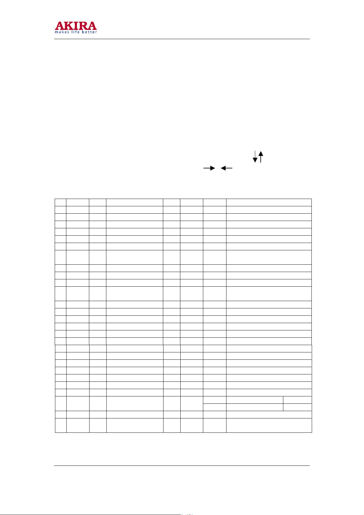
5. If the adjusting is default, please restore the data as previous or adjust according the table as
follows.
No Item Value Meaning No Item Value Meaning
1 RCUT 20* Red cut-off 35 VP 60 01 60Hz vertical center
2 GCUT 38* Green cut-off 36 HITS FD 50Hz/60Hz vertical size
3 BCUT 44* Blue cut-off 37 VLIN 0A Vertical linearity
4 GDRV 40* Green drive 38 VSC 06 Vertical S correction
5 BDRV 40* Blue drive 39 VLIS FF 50Hz/60Hz vertical linearity
6 CNTX 3F Contrast maximum 40 DPC 00 50Hz pillow distortion correction
7 BRTC 30 Brighter center 41 DPCS 00 50/60Hz pillow distortion
correction
8 COLC 50 Color center 42 KEY 00 50Hz keystone distortion
9 TNTC 40 Tint center 43 KEYS 00 50/60Hz keystone distortion
10 COLP 10 Color center of PAL 44 WID 00 50Hz horizontal size
11 COLS 40 Color center of
SECAM
12 SCNT 0F Sub-contrast 46 VCP 00 Vertical compensation
13 CNTC 20 Sub-contrast center 47 CNR 00 Coner correction
14 CNTN 08 Sub-contrast minimum 48 HCP 00 Horizontal compensation
15 BRTX 20 Sub-bright maximum 49 SBY 08 SECAM B-Y
16 BRTN 20 Sub-bright minimum 50 SRY 08 SECAM R-Y
17 COLX 7F Sub-color maximum 51 RAGC 16 R.F. AGC
18 COLN 00 Sub-color minimum 52 AFT 40* Auto frequency tune
19 TNTX 35 Sub-tint maximum 53 HAFC 00 AFC Gain
20 TNTN 28 Sub-tint minimum 54 V25 55 25 percent Volume
21 ST 3 3F TV-3.58 sharpness 55 V50 6F 50 percent Volume
22 SV 3 3F AV-3.58 sharpness 56 BRTS 00 Sub-bright
23 ST 4 20 TV-4.43 sharpness 57 VM 2 30 (CTS-763A)
24 SV 4 3F AV-4.43 sharpness 58 MOD0 21 Mode 0
26 SHPN 1A Sharpness minimum 60 MOD2 0C Mode 2
27 TXCX 36 OSD contrast
maximum
45 WIDS 00 50/60Hz horizontal size
06 For 14 and 21 inches Mode 1 25 SHPX 30 Sharpness maximum 59 MOD1
17 For 25 and 29 inches Mode 2
61 SELF
VCO
7G* Self-diagnosis VCO
Model No: 21HCS3Ve_21HCS3Wn
Version 1.0
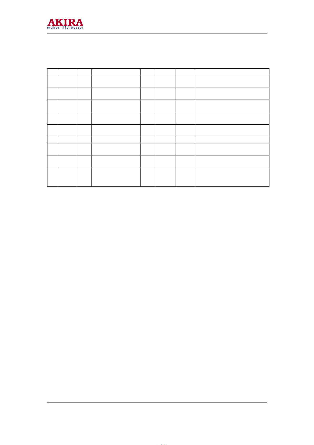
No Item Value Meaning No Item Value Meaning
28 RGCN 16 OSD contrast
minimum
29 VMO 7C VCD data 0 63 SELF
30 VM 1 00 VCD data 1 64 SELF
31 HPOS 0B Horizontal position 65 SELF
32 VP 50 04 50 Hz vertical center 66 SELF
33 HIT 19 50 Hz vertical size 67 OSD 00 OSD width adjustment
34 HPS 02 50/60Hz horizontal
center
69 MOD3 07 Language 70 ZOOM
71 ZOOM
OUT
HIT
Note:
1. The items with * in value are very special, do not adjust them at random. The items(1-5) are
2. The general secret code is 2175.
3. If you find the threadlike disturbance on the top of picture, please adjust the VM 2 in the items
4. When E PROM does not work, please exchange the same model chip with data that the
0b Zoom out height
used to debug white-black-balance of set.
and make its value come to 34.
manufacture has already input. 2
62 SELF
AGC
BRTC
CNTC
TNTC
COL
68 OPT 27 Option
IN HIT
69* Self-diagnosis AGC
75* Self-diagnosis bright center
00* Self-diagnosis contrast center
32* Self-diagnosis tint center
23* Self-diagnosis color center
3F Zoom in height
5
Model No: 21HCS3Ve_21HCS3Wn
Version 1.0

6
TYPICAL FAILURE ANALYSE
1. Three-None (no raster, no picture, no sound)
This failure is mainly caused by big-power circuit such as power supply, horizontal scanning, vertical
scanning.
The detail checking and repairing steps are as follow.
Model No: 21HCS3Ve_21HCS3Wn
Version 1.0

Model No: 21HCS3Ve_21HCS3Wn
Version 1.0
No
Check if V513 collect-emitter
was broken down
Check R502,F501, power
switch, AC cord and plug
Check V513,V512,F501,R502,VD503
300V
Test voltage of V513 base
0.6V
Check T501,VD517
C515,C517,VD552
VD553-VD555
V432,C435,C436
T401,C443,VD411
Voltage of C507
0V
Yes
0V
Check if it get right
when cut off V706
Yes
Test the voltage
of N701 Pin42
4.5-5.5V
CPU has sent the
power-off signal
0V
300V
Check the voltage
of V513 collector
Check T501
>1V
Check V513
0V
Check if V706
is broken down
Test the voltage of C461
<50V
Cut off W320
N0 variation
Test other voltage such
as 180V,24V and 12V
Low
V553,VD561,RP551
R569,V706,V512
C513,VD515,V511
0V
Check VD 551, C561
115V
Recover W320,unplug
XS 401 for a while,then
test the voltage of C561
No variation
Check V432,T401
T402,VE 601
Check L407, L408,
VE601,VD411,C443
115V
Normal
>130V
115V
N201 pin 8 voltage
9V
N201 pin32 voltage
2V
V431 pin C voltage
24V
Check R431,V431
Others
Check V432 pin C voltage
115V
Check T401,V432,R435 Check T401
Check R552,V553,VD561
VD515,V511,V512,R555
Others
Check Z203,C209,N201
0V
Check VD553,C563,R434
C434,T402,C432,V431,R550
0V
7
 Loading...