

Page 1

P
P
P
S
S
S
r
r
r
e
e
e
o
o
o
r
r
r
j
j
j
v
v
v
e
e
e
i
i
i
c
c
c
c
c
c
t
t
t
e
e
e
i
i
i
o
o
o
M
M
M
n
n
n
a
a
a
n
n
n
T
T
T
u
u
u
V
V
V
a
a
a
l
l
l
Page 2

V
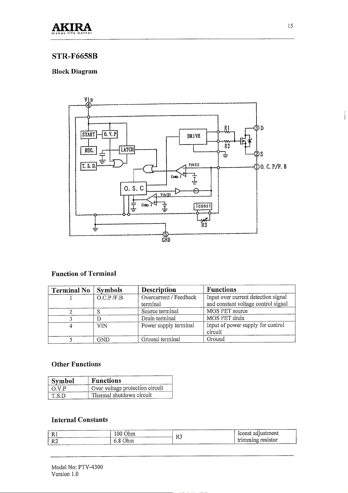
T
P
:
p
u
o
r
G
l
e
d
M
M
M
o
o
o
d
d
e
e
l
l
G
G
r
r
o
o
u
u
p
p
:
:
P
P
T
T
V
V
CHASSIS: PDT-6
2
MODEL:
PTV-4300
Model No: PTV-4300
Version 1.0
Page 3

CONTENTS
1 General Description & Safety Instructions ……………………… .4
1.1 General Description …………………………………... ……..4
1.2 Maintenance Instructions …………………………………….5
1.3 Electrical Specification ………………………………………5
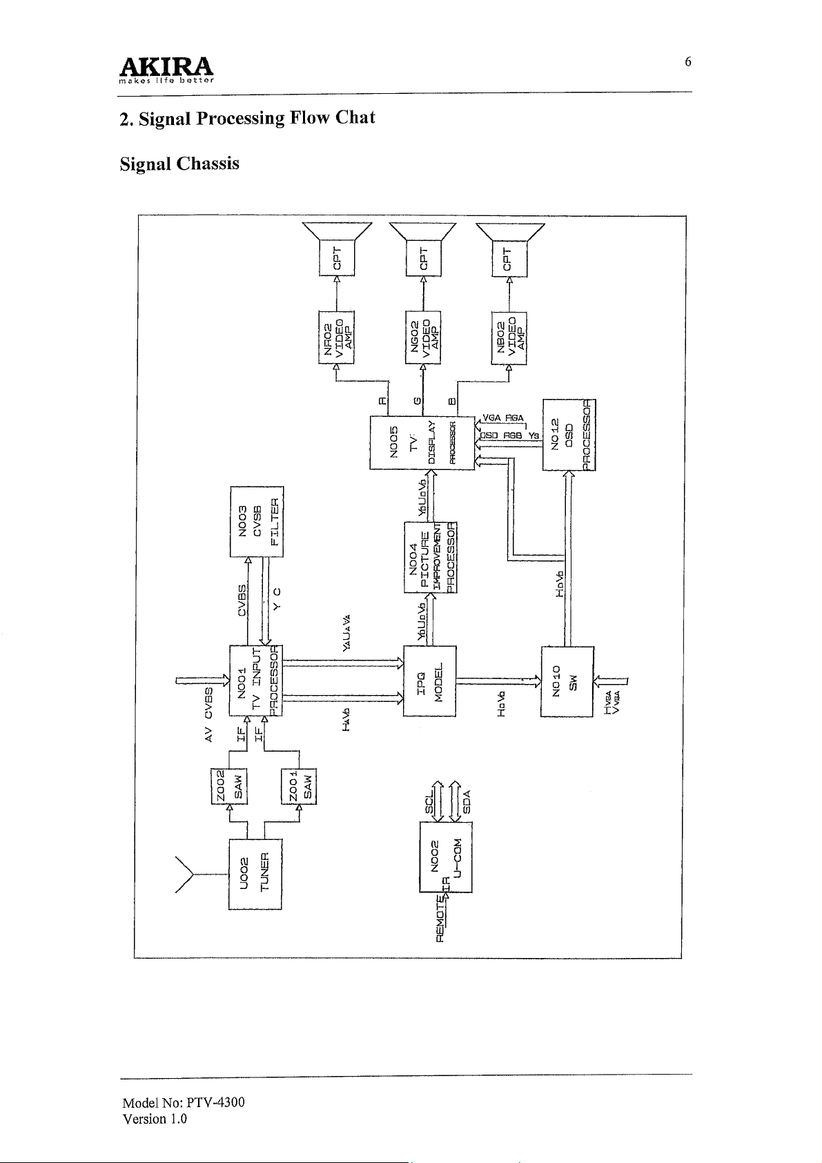
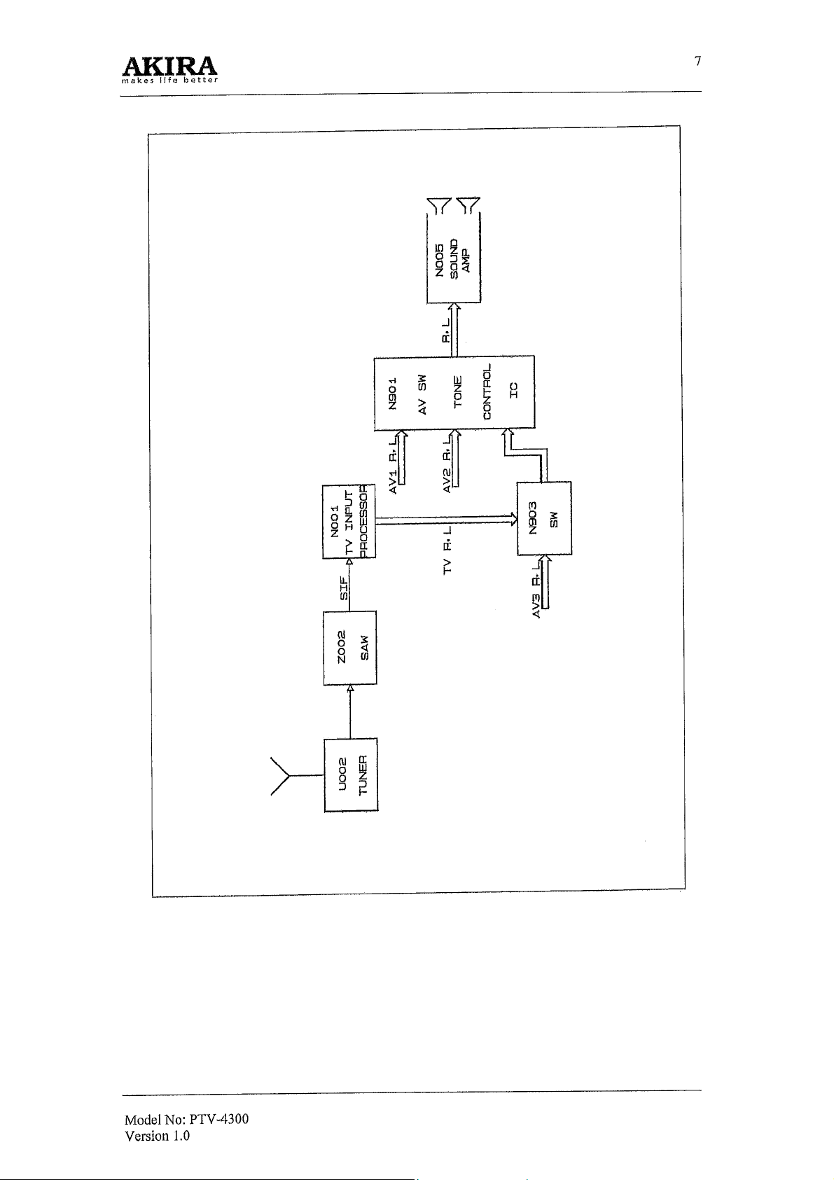
2 Signal Processing Flow Chart ………………………………… ….6
3 Troubleshooting Charts ……………………………………… ….10
3.1 Safety Precaution ………………………………………… ..10
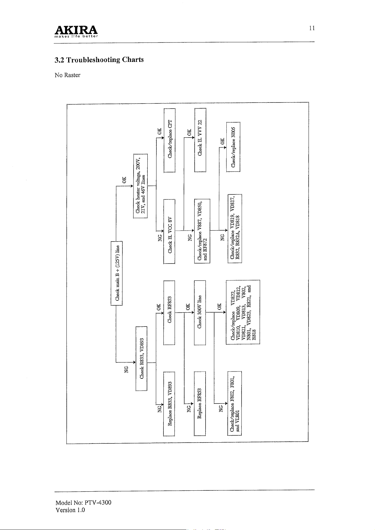
3.2 Troubleshooting Charts …………………………………… .11
4 Characteristics of Pins of Main ICs .............……………………..14
3
5 Convergence Adjustment ……………………………………… ..28
5.1 Description of Function Keys on Remote Controller for
Convergence Adjustment ……………………………… …..28
5.2 Convergence Adjustment Procedures ………………………29
2
6 I
C-bus Data …………………………………………………… ..33
7 Parts List & Replacement Parts List ………………………… ….36
8 Appendix …… …………………………………………………...62
8.1 Printed Circuit Board …………………………………….....62
8.2 Schematic Diagram ……………………………….. ……….64
8.3 Exploded View …………………………………….. ………65
8.4 BPBT Board ……………………………………….. ………66
8.5 Circuit Diagram ……………………………………… …….67
Model No: PTV-4300
Version 1.0
Page 4

1. General Description & Safety Instructions
1.1 General Description
WARNING!
In order to prevent electric shock, do not remove cover.
No user-serviceable parts inside refer servicing to qualified service personnel.
Features
Conventional color TVs apply 50Hz/60Hz alternate scanning and scan a picture in two separate fields,
which results in distinct scanning structural lines and horizontal flicker. As the TVs can display only
25/30 frames of picture per second, it cause wide-range image flicker. The larger the TV screen is, the
more conspicuous the problems are. Therefore, watching this kind of TV, you are susceptible to
eyestrain.
With the world's the state of the art digital inverter technology, our rear projection TV is an improved
product for better performance. With 60Hz progressive scanning, the RPTV can display a whole frame
of picture per scanning and increase display frequency from 25 frames of picture per second to 60. At
the same period of time, the RPTV can scan lines of up to 1250, two times as many as the conventional
TVs. The RPTV removes completely wide range image flicker and horizontal flicker, and offers
sharper and more lifelike pictures.
• Precision vision: With progressive scanning, the RPTV automatically increases vertical
frequency from 50Hz to 60Hz and horizontal frequency from 15625Hz to 31250Hz.
• Automatic white balance correction: The RPTV correct automatically white balance each
power-on, which avoids color distortion due to long time use and delivers consistently vivid
color.
• VGA terminal: You may connect a computer to the VGA terminal on the RPTV and use the
RPTV as a large-screen multimedia display terminal, through which you can surf Internet
and play games.
• Advanced projection tube" High brightness and high-resolution projection tube of the
world's advanced level guarantees high brightness and reliable focus performance.
Other features
• 7" projection tube (3 pieces)
• 470MHz CATV ready
• Multi system/digital NICAM reception
• Theatre and music surround system
• Still picture
• On/off timer
• Wide power voltage range
• Digital frequency synthesized tuner
• Easy operation
• High-contrast and high-luminance black optical screen
• 236(0-~235) programs preset
• Hi-Fi audio system
• DVD VIDEO COMPONENT IN terminals
• No-signal-off
2
C bus control
• I
• Digital matrix convergence
• Luminous remote controller
• Program swap
Model No: PTV-4300
Version 1.0
4
Page 5

1.2 Maintenance Instructions
• If a problem occurs (such as no picture or no sound), or if smoke or an abnormal odor starts
to come out from the RPTV, immediately unplug the power cord and contact the service
agency as soon as possible.
• High voltage inside! Non-professionals can not open the back cover.
• Do not expose the RPTV to direct sunshine or put it near heat sources.
• Do not put the RPTV in a place subject to moisture and dust or where the rain can reach.
• Set up a lightning arrester when an outdoor antenna is used. Do not turn on the RPTV in
thunder days. At lightning intervals, pull off the power cord and antenna cable.
• Please turn off power supply of the RPTV while outgoing. In ease of the RPTV is not used
for a long period of time, please pull off the power cord and antenna cable.
• Do not put anything on the RPTV, especially objects filled with water or chemical material
on top of the RPTV. Doing so may cause deformation to the cabinet and screen or water to
spill into the RPTV.
• Install the RPTV in a place with good air circulation. Do not cover the ventilating holes to
prevent the RPTV from overheating.
• Avoid hard objects hitting on .the RPTV (especially screen) or severe vibration when
moving the unit. Doing so may adversely affect location of the inside lens.
• To prevent the RPTV from falling off or tip over, place the RPTV on stable and flat surface
without vibration and fix it according to Operation Manual.
• Do not switch the RPTV on and off frequently. Doing so may shorten life span of the RPTV.
• Do not switch on or off the RPTV by plugging or pulling off the plug.
• When using TV games, computers and similar products with your RPTV, keep the
brightness and contrast functions at low setting. If a fixed pattern is left on the screen for a
long period of time, especially at a high brightness or contrast setting, the image can be
permanently imprinted onto the screen, which is not covered by your warranty.
• Wipe the cabinet regularly using only a soft cleaning cloth.
• If the cabinet is particularly dirty, soak a soft cloth in water to which a small amount of
neutral detergent has been added, and dry it to wipe the cabinet. Do not use organic solvent.
• Keep the screen dry. Wipe the screen using a dry soft cloth. Observe the instructions if using
a synthetic rag.
1.3 Electrical Specification
Rated voltage AC 150 ~ 260V, 50Hz / 60Hz
Rated power consumption ~250W
Receiving channels VHF: C1 ~ C12 UHF: C13~C57 CATV: Z1~ Z37
Color system PAL 4.43, PAL 3.58, NTSC 3.58, NTSC 4.43,
SECAM
Sound system D / K, I, M, B/G
Audio output 15W + 15W (THD = 7%)
5
Model No: PTV-4300
Version 1.0
Page 6
Page 7
Page 8
Page 9
Page 10

10
3. Troubleshooting Charts
3.1 Safety Precaution
WARNING:
Service should not be attempted by anyone unfamiliar with the necessary precaution on the RPTV. The
following are the necessary precaution to be observed before servicing.
1. Cold ground near the point to be tested, not warm ground on the power supply board shall be 0
reference when testing voltage at circuit joints.
2. In the process of servicing, do not turn on/off the set quickly and frequently. The minimum
internal shall be more than 30s.
3. Always be certain that the wires are connected or wrapped as it was after completion of servicing.
4. Keep signal and supply wires from high voltage or high temperature components.
5. Be careful and do not scratch the screen and lens when removing the screen.
6. Normally, do not perform any operation (e.g. press VOLUME UP/DOWN buttons) under the item
of "INIT" of Data menu for final adjustment in order to avoid initiating final-ad-justed data.
Product Safety Notice
Many electrical and mechanical parts in this chassis have special safety-related characteristics.
These characteristics are often passed unnoticed by a visual inspection and the protection afforded by
them cannot necessarily be obtained by using replacement components rated for higher voltage,
wattage, etc. Replacement parts, which have these special safety characteristics are identified in this
manual and its supplements.
Electrical components having such feature are identified by printing on the schematic diagram and the
part list. Before replacing any of these components, read the part list in this manual carefully.
Unauthorized substitutions may result in fire, electric shock or other hazards.
Model No: PTV-4300
Version 1.0
Page 11
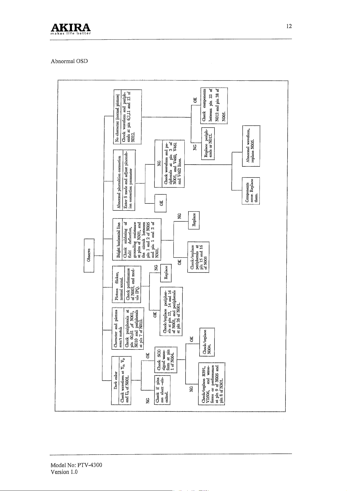
Page 12
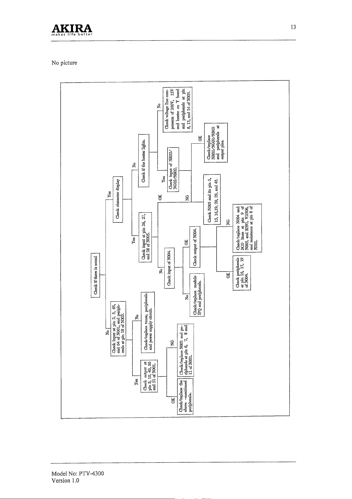
Page 13
Page 14
123456897
N
Nc N
N
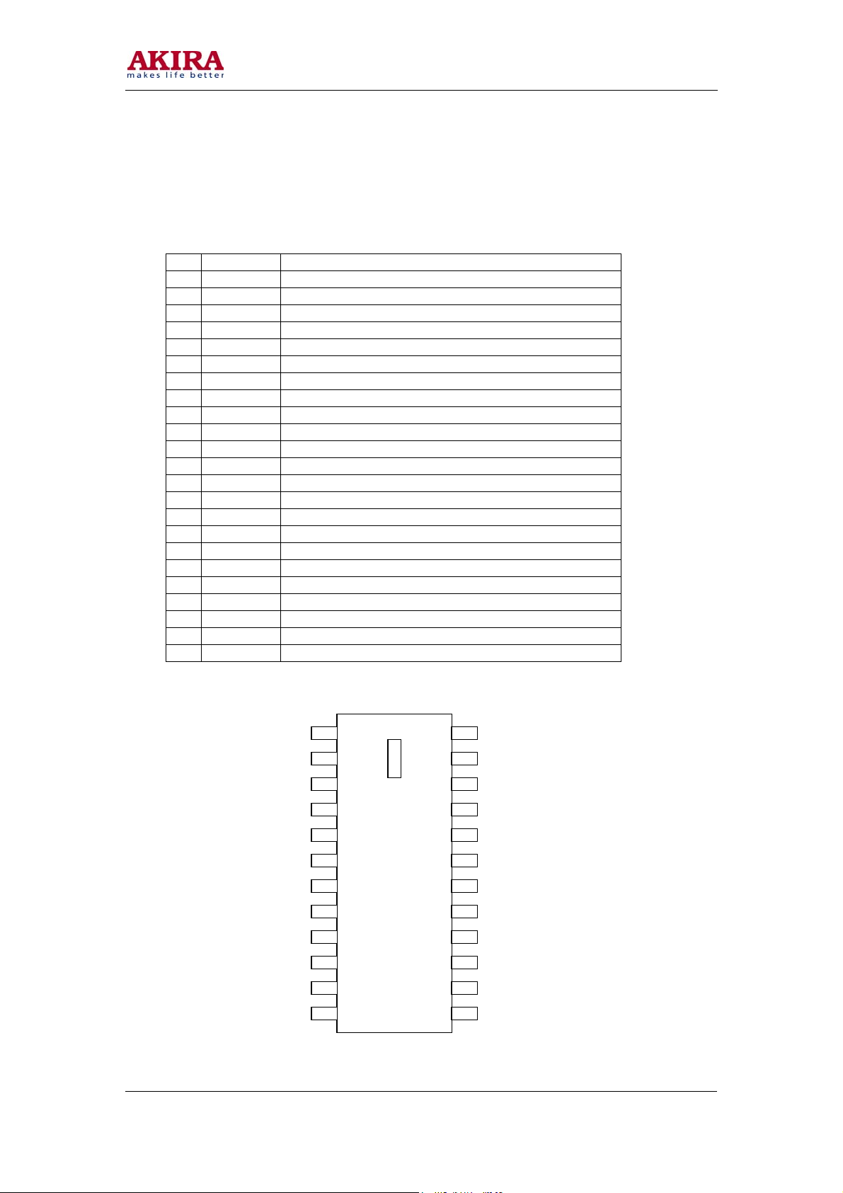
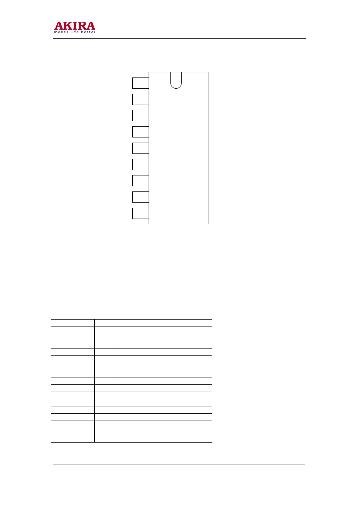
4. Characteristics of Pins of Main ICs
TDA9178
Pinning and external components of the TDA9178:
1 Sc Sandcastle input pin
2 Nc Not connected pin
3 ADextl External AD-conversion #1 input pin
4 ADext2 External AD-conversion #2 input pin
5 Adext3 External AD-conversion #3 input pin
6 Yin Luminance input pin
7 ADR Address selection input pin
8 uin -(B-Y) signal input pin
9 Vin -(R-Y) signal input pin
10 TP Testpin connected to ground
11 SCL I2C.bus: clock input pin
12 Nc Not connected pin
13 Nc Not connected pin
14 SDA I~C-bus: data input pin
15 DECDIG Decoupling digital supply
16 Vout -(R-Y) signal output pin
17 Vout -(B-Y) signal output pin
18 Vee Ground pin
19 Yout Luminance output pin
20 Vee Supply-voltage pin
21 Sout Luminance output for SCAVEM
22 CF Cue-flash output pin
23 Nc Not connected pin
24 Nc Not connected pin
Model No: PTV-4300
Version 1.0
Sc
c
ADext1
ADext2
ADext3
Yin
ADR
Uin
Vin
TP
SCL
Nc
TDA9178
10
11
12
13
14
15
16
17
18
19
Sc
20
21
22
23
24
c
CF
Sout
Vcc
Yout
Vee
Uout
Vout
DEC
SDA
c
DIG
14
Page 15
Page 16
Page 17
Page 18
Page 19
19
TDA6111Q
Video output amplifier
General description
The TDA611Q is a video output amplifier with 16 MHz bandwidth. The device is contained in a single
in-line 9-pin medium power (DBS9MPF) package, using high-voltage DMOS technology, intended to
drive the cathode of a color CRT.
Quick reference data
Symbol Parameter Conditions Min. Typ. Max. Unit
V
DDH
V
DDL
I
DDH
I
DDL
V
I
V
OC,
Vfb
T
stg
T
amb
high level supply voltage 0 - 250 V
low level supply voltage 0 - 14 V
quiescent high voltage supply
current
quiescent low voltage supply
current
input voltage 0
output voltage
storage temperature -55 - +150 °C
operating ambient temperature -20 - +65 °C
VOC=0.5VDD
VOC=0.5VDDH 5.0 6.8 8.0 mA
7.0 9.0 11.0 mA
H
-
VDD
-
L
VDD
VDD
V
L
V
H
Pinning
Symbol Pin Description
Vip 1 non-inverting voltage input
V
2 supply voltage LOW
DDL
Vin 3 inverting voltage input
GND 4 ground, substrate
Iom 5 black current measurement output
V
DDH
6 supply voltage HIGH
Vcn 7 cathode transient voltage output
Voc 8 cathode DC voltage output
Vfb 9 feedback voltage output
Model No: PTV-4300
Version 1.0
Page 20
V
V
DDL
Vin
GND
Icm
V
DDH
Vcn
Voc
Vfb
ip
1
2
3
4
5
6
7
8
9
TDA6111Q
Pin configuration
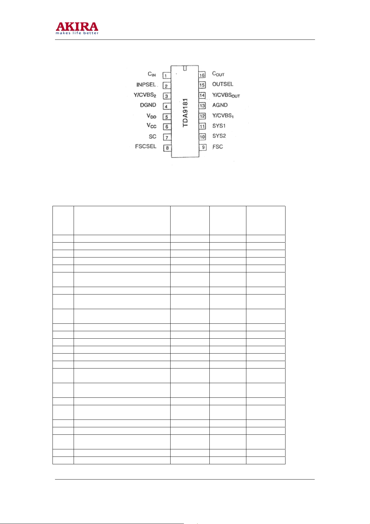
TDA9181
Integrated multistandard comb filter
Pinning
Symbol Pin Description
CIN 1 chrominance input signal
INPSEL 2 input switch select input
Y/CVBS2 3 luminance or CVBS input signal 2
DGND 4 digital ground
VDD 5 digital supply, voltage
VCC 6 analog supply voltage
SC 7 sandcastle input signal
FSCSEL 8 subcarrier select input
FSC 9 subcarrier input signal
SYS2 10 standard select 2 input
SYS1 11 standard select 1 input
Y/CVBS1 12 luminance or CVBS input signal 1
AGND 13 analog ground (signal reference)
Y/CVBSOUT 14 luminance or CVBS output signal
OUTSEL 15 output switch select input
COUT 16 chrominanee output signal
Model No: PTV-4300
Version 1.0
20
Page 21
21
Pin configuration
Table 1: Pin Function, Reference Voltage and Resistance to Ground of TDA9178
Resistance
Pin
Short Description
No.
1 Sandcastle Pulse Input 0.77 0.77 Infinity
2 Not Connected Pin 0 0 0.1
3 A/D Input 1 0 0 0.1
4 A/D Input 2 0 0 0.1
5 A/D Input 3 0 0 0.1
6
7 Ground 0 0 0
8
9
10 Not Connected Pin 0.41 0 0
11 Clock Signal Jumper 3.2 Variant 3.2 Variant 5.8K
12 Not Connected Pin 0 0 0
13 Not Connected Pin 0 0 0
14 Data Signal Jumper 2.9 Variant 3.1 Variant 5.8K
15 De-coupling Capacitor 5.07 5.06 Infinity
16
17
18 Ground 0 0 0
19
20 +SV Power Supply +8.01 8.01 0.9K
21 VM Signal Output 2.21 2.27 Infinity
22
23 Ground 0 0 0
24 Ground 0 0 0
Model No: PTV-4300
Version 1.0
Inverter YD Luminance Signal
Input
Inverter UD Color Difference
Signal Input
Inverter VD Color Difference
Signal Input
V Color Difference Signal Output
after Transient Improvement
U Color Difference Signal Output
after Transient Improvement
Luminance Signal (Y) Output after
Transient Improvement
Low Frequency Flicker Detection
Output
Static
Voltage
1.51 1.47 0.1
1.50 1.46 0.1
1.51 1.47 0.1
2.63 2.67 Infinity
2.63 2.64 Infinity
0.73 0.8 Infinity
2.72 0.73 Infinity
Dynamic
Voltage
to
Ground
Page 22
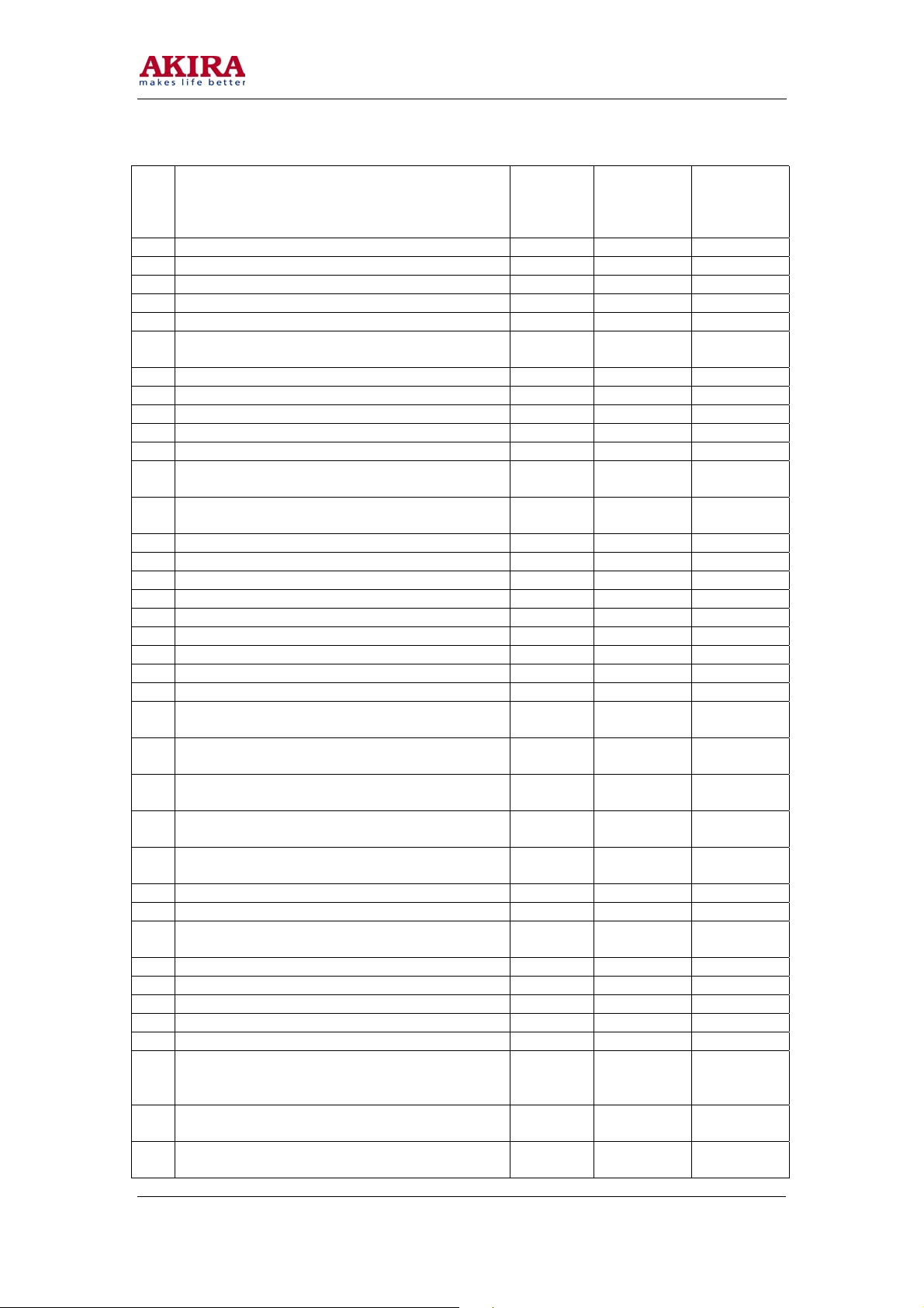
Table 2: Pin Function, Reference Voltage and Grounding Resistance of TDA9321
Resistance
Pin
No.
Short Description
1 Sound IF Signal Processing AGC Filter 2.77 3.11 Infinity
2 Video IF Signal Input 4.65 4.62 69.8K
3 Video IF Signal Input 4.65 4.62 69.8K
4 PIF Amplifier AGC Filter for External Video 1.29 4.01 Infinity
5 2nd Sound IF Signal Output 3.37 3.36 Infinity
Detection Phase-locked Loop Filter for External
6
Video
7 Connects IF Coil T101 3.81 3.79 Infinity
8 Connects IF Coil T101 3.81 3.79 0
9 Ground 0.11 0.11 3.3K
10 TV Video Signal Output 4.81 3.12 0.9K
11 8V Power Supply 8,13 8.09 Infinity
TV Video Signal Input Processed by Sound
12
Trapper
TV Video Signal Output Processed by Group
13
Delay line
14 TV Video Signal. Input 3.57 3,57 Infinity
15 Not Connected Pin 0.51 0.13 88.K
16 Connects Video Signal from AV2 Terminal 3.52 3.51 Infinity
17 Not Connected Pin 0,5 0.13 88.5K
18 CVBS2 Video Signal Input 4.35 3.57 Infinity
19 M System Control Signal Output 4.91 4.91 Infinity
20 Connects Y Luminance Signal from S1 Terminal 3.53 3.51 Infinity
21 Connects Chrominance Signal from S 1 Terminal 0.22 0.22 99.1K
22 Not Connected Pin 0.11 0.11 Infinity
Connects Luminance Signal (Y-3) from $3
23
Terminal
Connects Chrominance Signal (C-3) from S3
24
Terminal
Outputs Switching Signal SYSI for Controlling
25
Comb Circuit
TV/AV Video Signal Output, to Comb Circuit
26
SAA4961
Outputs Switching Signal SYS2 for Controlling
27
Comb Circuit Status
28 Luminance Signal Input from Comb Circuit 3.63 0 Infinity
29 Chrominance Signal Input from Comb Circuit 0.22 0 99.3K
Color Sub-carrier Signal Output, to Comb Circuit
30
SAA4961
31 Ground 0.11 0.11 0
32 Not Connected Pin 3.44 3.71 Infinity
33 Power De-coupling Filter Capacitor 5,02 5.01 Infinity
34 Video Signal Output, to AV Output Port 2.19 2.6 Infinity
35 Not Connected Pin 4.12 3.11 37.3K
Connects DVD Jack, Inputs V Color Difference
36
Signal (or External R1 Primary Color Signal
Input)
Connects DVD jack, Inputs Y Luminance Signal
37
(or External G1 Primary Color Signal Input)
Fixed Level RGB1 Input with Fast-Blanking input,
39
Forced into
Model No: PTV-4300
Version 1.0
Static
Voltage
Dynamic
Voltage
to
Ground
3.49 2.89 Infinity
3,52 3.94 Infinity
2.94 3.37 Infinity
3,53 3.51
0.22 0 99.0K
0.11 0 Infinity
3.44 4 Infinity
5.01 5.00 Infinity
4.25 0 Infinity
3.29 4.79 Infinity
3.31 2.82 Infinity
2.75 2.74 22.0K
22
Page 23

Resistance
Pin
No.
Short Description
Static
Voltage
Dynamic
Voltage
to
Ground
Connects DVD Jack, Inputs U Color Difference
38
Signal (or Extenaal B1 Primmy Color Signal
3.16 2.80 Infinity
Input)
40 Not Connected Pin 3.14 4.03 Infinity
41 Not Connected Pin 3.35 2.84 Infinity
42 Not Connected Pin 3,36 2.86 Infinity
43 Not Connected Pin 3.36 2.86 Infinity
44 Ground 0.11 0.11 0
45 8V Power Supply 8.17 8.16 0.9K
46 I2C Bus Clock Signal Jumper
47 I2C Bus Data Signal Jumper
3.2-3.26
Variant
2.96-3.12
Variant
3.44 5.8K
3.37 5.9K
48 Not Connected Pin 0.80 0.12 173.5K
Luminance Signal Output, to Inverter Processing
49
Assembly
U Color Difference Signal Output, to Inverter
50
Assembly
V Color Difference Signal Output, to Inverter
51
Assembly
2.87 3.46 Infinity
2.45 2.27 Infinity
2.43 2.42 Infinity
52 Color Phase-demodulation Filter Capacitor (PLL) 4.56 5.05 Infinity
53 SECAM De-modulation Filter Capacitor 4.12 0 Infinity
54 4.43 MHZ Crystal 2.52 2.55 Infinity
55 3.582 MHZ Crystal 2.54 2.54 Infinity
56 3.579 MHZ Crystal 2.54 2.54 Infinity
57 3.575 MHZ Crystal 2.54 2.54 Infinity
58 Line Phase-discriminator 1 Filter Network 3.93 4.18 Infinity
59 Not Connected Pin 0.84 0.84 Infinity
Horizontal Sync. Signal Output HA, to Inverter
60
Circuit
0.5 0.5 Infinity
61 Vertical Sync. Output VA, to Inverter Circuit 0.17 0.16 Infinity
62 Radio AGC Control Voltage Output 6.67 6.77 8.8K
63 Sound IF Signal Input 4.64 4.63 69.8K
64 Sound IF Signal Input 4.64 4.63 69.8K
23
Model No: PTV-4300
Version 1.0
Page 24

24
Table 3: Pin Function, Reference Voltage and Grounding Resistance of P87C766 (N002)
Pin
No.
1 PIP Hue Control Output 0.14 0.37 Infinity
2 50/60Hz Control Signal Output 0.14 0.24 Infinity
3 Geomagnetism Con'ection Control Output 0.14 0.46 Infinity
4 Mute Control Signal Output 3.08 0 12.3K
5 VGA2 Protection Mode Setting, High level is active 0 0 0
VGA Sync. Switch Signal Output, Low Level Selects
6
VGA Sync. Signal
7 VGA Identification Signal Input 0 0 52.6K
VGA Protection Signal Input, "PROTECTION" is
8
displayed when the screen is in protection mode.
9 External Mute Control Output 3.56 4.88 12.4K
10 Button Control Component 5.02 4.88 10.61K
11 Button Control Component 5.02 4.88 10.5K
TV/AV Switching Voltage Output Audio Switching Signal
12
between TV and AV3,
13 Standby/Power-on Control Signal Output 3.82 0 17.3K
14 Not Connected Pin 0.20 0.4 Infinity
15 Not: Connected Pin 0.20 0.41 Infinity
16 Not Connected Pin 0.20 0.47 Infinity
17 Indicator Control Signal Output 0 0 12.7K
18 Sound System Switch Control Signal Output 0 0 12.9K
19 Sound System Control Signal Output 0 0 12.9K
20 Not Connected Pin 0 0.45 Infinity
21 Ground 0 0 0
22 Not Connected Pin 0 0 Infinity
23 Not Connected Pin 0 0 Infinity
24 Not Connected Pin 0 0 Infinity
25 Not Connected Pin 0 0 Infinity
26 Not Connected Pin 0.16 0.55 Infinity
27 Not Connected Pin 0.16 0.54 Infinity
Power Supply +5V to CPU Analog Signal Processing
28
Circuit
29 Ground 0 0 0
30 Not Connected Pin 0.18 0.51 Infinity
Clock Oscillating Signal Input, Connects 12MHZ Crystal
31
Oscillator
Clock Oscillating Signal Output, Connects !2MHZ Crystal
32
Oscillator
33 CPU Reset Pin, High Level Voltage is Active 0 0 47.2K
34 Not Connected Pin 5.02 4186 Infinity
Bus Production Mode Setting, Ex-faetory Mode is High
35
Level
36 1st Bus Signal Output, Connects Clock Signal 5,02 4.77 5.8K
37 Remote Signal input 4.96 4.82 30.6K
38 1st Bus Control Output, Connects Data Signal 5.01
2nd Bus Signal Output, Connects Clock Signal, to
39
controlled Circuit
2nd Bus Signal Output, Connects Data Signal, to
40
Controlled Circuit
41 Not Connected Pin 5.01 4.87 12.5K
42 CUP+SV Supply Voltage 5.01 4.87 2.5K
Short Description
Static
Voltage
0 0 12.4K
0.73 4.88 Infinity
0 0 12.4K
5.03 4.88 2.5K
2.02 1.95 Infinity
2.64 5.54 Infinity
5.02
5.01
5.01
Dynamic
Voltage
4.4
Variant
4.72
Variant
3.3
Variant
3.1
Variant
Resistance
to
Ground
17.3K
5.9K
5.8K
5.8K
Model No: PTV-4300
Version 1.0
Page 25

Table 4: Pin Function, Reference Voltage and Grounding Resistance of
TDA9332H(N005)
Pin
No.
1 Vertical Drive Negative Output A 2.24 2.31 Infinity
2 Vertical Drive Positive Output B 2.26 2.31 Infinity
3 E/W Correction Pulse Output 3.36 3.26 15.0K
4 EHT High Voltage Detection Signal Input 1.54 1.46 16.2K
5 Quick Detection Input 0.07 0.06 Infinity
6 Ground 0 0 0
7 Data Circuit De-coupling 5.00 5.00 Infinity
8 Line Actuating Pulse Output 0.67 6.67 81.5K
Sandcastle Pulse Output, to Color Transient Improving
9
Circuit TDA9178
10 2nd Bus Signal Clock Signal Jumper 3.04
11 2nd Bus Signal Data Signal Jumper 2.9
12 Not Connected Pin 4.17 4.95 146.8K
13 Line Retrace Pulse Input 0.60 0.57 Infinity
14 Dynamic Phase Correction Pulse Input 3.56 3.20 67.8K
15 Field Saw tooth Forming Capacitor C507 0 0.03 Infinity
Reference Current Forming Resistor R512 for Field Saw
16
tooth Generator
17 Line Actuating Power Input 8.08 8.06
18 Connects Regulated Supply Filter Capacitor C510 4.75 4.75 Infinity
19 Ground 0 0 0
Line Voltage-operated Oscillator Crystal C501
20
(12MHZ)
21 Connects 12MHZ Crystal 1.05 1.07 Infinity
22 Not Connected Pin 0.04 00.04 Infinity
23 Selected VGA or TV/AV Vertical Syne. Signal Input 0.02 0.04 157.5K
24 Selected VGA or TV/AV Horizontal Syne. Signal Input 0.99 0.39 Infinity
25 Not Connected Pin 0.87 0.30 43.5K
26 V Color Difference Signal Input 3.58 3.61 Infinity
27 U Color Difference Signal Input 3.60 3.51 Infinity
28 Y Luminance Signal Input 3.41 3.46 Infinity
29 Ground 0.05 0.04 0
30 VGA Interface for R Primary Color Signal Input (R1) 2.60 2.60 Infinity
31 VGA Interface for G Primary Color Signal Input (G1) 2.60 2.60 Infinity
32 VGA Interface for B Primary Color Signal Input (B1) 2.60 2160 Infinity
RGB1 Input with Blanking Input, Set to High Level,
33
VGA Signal is Selected to Bus Setting
34 Peak White Limiting Filter Capacitor 0.18 0.18 Infinity
35 R Primary Color Signal Input for Character Display (R2) 3.55 3.54 Infinity
G Primary Color Signal Input: for Character Display
36
(G2)
37 B Primary Color Signal Input for Character Display (B2) 3.54 3.54 Infinity
38 RGB2 Input with Blanking Input Blkz 0 0 1.0K
39 +SV Power Voltage 8.00 8.0 1.0K
R Primary Color Signal Output, to Final Playback
40
Circuit
Short Description
Static
Voltage
0.77 0.77 Infinity
3.89 3.89 39.2K
1.22 1.05 Infinity
1.98 0.04 1.8K
3.54 3.54 Infinity
2.50 2.50 3.0K
Dynamic
Voltage
3.1
Variant
3.0
Variant
Resistance
to
Ground
5.9
5.9K
49.9K
Charged
25
Model No: PTV-4300
Version 1.0
Page 26

26
G Primary Color Signal Output, to Final Playback
41
Circuit
B Primary Color Signal Output, to Final Playback
42
Circuit
2.48 2.53
2.51 2.56
3.0K
3.0K
43 Auto-Luminance Control Signal input 2.47 2.46 64K Charged
44 Black Current Detecting Signal Input 6.91 6.89 151.5K
Table 5" Pin Function, Reference Voltage and Grounding Resistance of PCA8516
(NO12)
Pin
No
Short Description
Operating
Voltage
1 Not Connected Pin 0.08 166.2K
2 Not Connected Pin 0.08 Infinity
3 Ground 0 0
4 Ground 0 0
5 Connects RC Filtering Network 2.31 Infinity
6 Inverter Vertical Position Pulse Input 0.13 158.2K
7 Inverter Horizontal Position Pulse Input 0.49 Infinity
8 Clock Signal 2.9 Infinity
9 Data Signal 3.1 5.7K
10 Connects 4MHZ Character Crystal Oscillator 2.38 Infinity
11 Connects 4MHZ Crystal Oscillator 2.28 Infinity
12 Ground 0.08 0
13 +5V Character Oscillating Reset Voltage is Active 5 3.4K
14 Ground 0 0
15 Connects 5V 5 2.4K
16 Character R Prilnary Color Signal Output 0.26 6.6K
17 Not Connected Pin 5 158.3K
18 Character G Primary Color Signal Output 0.24 6.5K
19 Not Connected Pin 5 162.0K
20 Character B Primary Color Signal Output 0 6.5K
21 Connects 5V Power Supply 5 2.3K
22 Character Blanking Output 0.26 2.9K
23 Ground 0 0
24 Connects +5V Power 5 2.4K
Resistance to
Ground
Model No: PTV-4300
Version 1.0
Page 27

Operating Voltage of Triode
Pos. No. b c e Pos. No. b c e
V201 0 4.9 0 V461 3.45 7.18 2.77
V251 4.3 4.9 4.95 V4.02 0.52 7.75 0
V250 4.92 0 4.95 V462 -10.87 -0.64 -11.47
V672 0.64 0 0 V460 -0.64 -19.27 -0.11
V612 7.57 2.97 7.39 V404 -20.2 126.3 -0.01
V671 0.65 0 0 V1005 0 4.6 0
V673 0.64 0. 0 V801 23.2 27.3 22.6
V102 0.7 0 0 V803 26.0 1,3' 26.6
V104A 2.81 8.12 2.15 V805 1.79 ,1.77 2.45
V103A 3.85 6.14 4.57 V804 0.74 4.95 0.61
V 103 3.87 6.14 4.57 V806 4.92 4.95 4.28
V 104 3,88 7.97 3.22 N803 26.6 -0.1 4.9
V 101 1.43 8.09 0.69 V807 8.7 27.2 8.1
V504 1.58 0.1 0 V802 6.8 36.2 8.1
V502 1.09 0 1.72 V832 5.90 7.55 5.23
V503 5.05 1.68 1.72 V831 5.84 7.6 5.22
Q1 1.23 6.95 0.46
27
Model No: PTV-4300
Version 1.0
Page 28

Page 29

29
5.2 Convergence Adjustment Procedures
Note: When performing after-sales service or repair, you usually need only to fine-adjust the crosshatch
in red and blue and make them be lined with green crosshatch on the basis of green crosshatch. It is no
necessary to perform other adjustments.
CONVERGENCE ADJUSTMENT
Notes: In the convergence mode, if the first two displayed characters are "P", it means PAL, and if "Q",
it means NTSC. In the two modes of DVD, the character display is the same as the two abovementioned modes. "V" stands for VGA mode. These characters are omitted in the following OSD
display description.
CONVERGENCE ADJUSTMENT IN PAL
I With receiving of PAL signal, and the volume to 0, press and hold MUTE button until the red
"MUTE" character becomes three colors (or white), then press MENU button on front panel of
TV to enter "S" mode (Press "S" button on the jig to enter "S" mode directly when in
production). Press yellow RECALL button to enter the phase of convergence adjustment, and the
red convergence crosshatch displays in the screen. Press DISPLAY button to switch into green
crosshatch signal.
Note" Generally speaking, you can go to Step IV, V, VI and VII directly.
1 Press TEXT button to clear fine/coarse adjusted data of the six channels in the RAM of con-
vergence IC.
Note: Normally speaking, do not reset the RPTV to 0. If it is necessary, exit convergence mode
and time it before your resetting.
2 Adjustment of static convergence in green. Press PIP button until the video image super-
imposes crosshatch testing signal. Press PICTURE MODE SELECTION button until character "DCGH" appears, then press POSITION UP/DOWN buttons to call up "DCGH"("
DCGV"). Press VOLUME UP/DOWN buttons to make the center of green line (field) of 5-
CH video test pattern locate at the center of the screen. Then press PIP button to conceal the
video image.
II Phase adjustment
a. Adjustment of H. fine adjustment and phase of horizontal test
i. Instate of crosshatch in green, press PICTURE MODE SELECTION button to call
up " FINE NODE", and press SWAP button to switch the cursor into green. Press
MUTE button until "P LOCK" appears. Now press POSITION UP button to
display the GV value of fine adjusted convergence at H#4/V#4 point as the
maximum value on the screen.
ii. Press AV button to call up "FINE PHASE", Press VOLUME UP/DOWN buttons
to make the peak appear at the vertical line at the right of horizontal center.
iii. Press AV button to call up "TEST PHASE". Adjust VOLUME UP/DOWN button
to make the cursor locate at the peak.
iv. Reset GV value at H#4/V#4 to "0".
Model No: PTV-4300
Version 1.0
Page 30

b Setting of start lines of fine-adjusted convergence (setting of STARTLINES)
i In the state of crosshatch in green, press PICTURE MODE SELECTION button to
enter "FINE MODE", then press VOLUME UP/DOWN buttons to set the GH fine
adjustment value at H#4/V#4 as maximum, and make the peak displays on the
screen.
ii Press AV button to call up "STARTLINES", then press VOLUME UP/DOWN
buttons till the peak displays at the center of the field. (Note: "START LINES" value
can only be odd number).
iii Return the GH fine adjusted value at H#4/V#4 to "0".
c Press PICTURE MODE SELECTION button to display "DCRH". Press POSITION UP/
DOWN buttons to call up "KGV3", and press VOLUME DOWN button to set KGV3 as a
larger data. If the cursor is off the horizontal center, press AV button to call up "COAR
PHASE", then press VOLUME UP/DOWN buttons to return the cursor to the original
position.
d Press PICTURE MODE SELECTION button until "DCRH" displays on the screen. Press
POSITION UP/DOWN buttons to call up "KGH3", and adjust VOLUME UP/DOWN buttons to set "KGH3" as a larger data. If the cursor is off the field center, press AV button to
call up "START VALUE", then press VOLUME UP/DOWN buttons to return the cursor to
the original position.
e "COUNTUP" Setting
i Press and hold AV button till "COUNTUP" appears, and press VOLUME
UP/DOWN buttons to make crosshatch signal basically be straight in the V/H
direction. (The recommended COUNTUP data: PAL 3D, and NTSC 3D.
III Coarse-adjustment of convergence in green
Press PICTURE MODE SELECTION button till "DCRH" appears, then press POSITION
UP/DOWN buttons to select coarse adjustment order as follows:
i Trim horizontal skew in green (KGH3).
ii Trim green horizontal pincushion distortion (KGH1)
iii Trim green horizontal amplitude (KGH2).
iv Trim green field pincushion distortion (KGV2).
v Trim field keystone distortion (KGV1).
vi Trim green field skew (KGV3).
IV Fine-adjustment of convergence in green
Press PICTURE MODE SELECTION button to call up "FINE MODE", press SWAP but
a
line to turn the cursor into green. Press DIGIT SELECTION button to select the point or
30
line adjustment. Press MUTE button to move or fix the cursor: (When OSD is "POINT
MOVE" or "LINE MOVE", press VOLUME UP/DOWN or POSITION.UP/DOWN buttons
to move the cursor up, down, left and right. When OSD is "POINT LOCK" or "LINE
LOCK", press VOLUME UP/DOWN or POSITION UP/DOWN buttons to adjust the dot or
line data).
Notes:
• In the process of fine adjustment, the cursor will change into 3 colors automatically. Press
MUTE button after adjusting a data, the cursor will return to original color.
• It is recommended to perform trimming fine errors from the center of the screen toward outside area in circumference in accordance with such an order as whirlpool-shape. In other
word, at first, trim fine error at the point of H#4/V#4 of the screen center, next trim each fine
point in circumference around outside of the 8 points, then trim other points in the same
way.
Model No: PTV-4300
Version 1.0
Page 31

• If adjusting one point to increase fine error of nearby ones, which are not adjusted, you
should adjust the data at your target point to make the error of nearby ones in the permissible
range. Otherwise the fine adjustment data of nearby point might not meet the requirement
even if the data reaches maximum.
• You can save the adjusted data by pressing MENU button. When OSD displays "DATA
OK", the data is saving, and when " DATA OK" disappears, it indicates the saving is complete.
• When adjusting the parameters of coarse and fine adjustment in green, it will activate the
convergence of the other two guns at the same time.
V Adjustment of convergence in red
a In convergence mode, press DISPLAY button to switch crosshatch state into red and green.
i Adjustment of static convergence in red, adjust "DCRH" and "DCRV" of coarse
adjustment convergence, so that superimpose the center of line-field in red with center
of line-field in green.
ii Trim horizontal skew in red (KRH2)
iii Trim horizontal linearity distortion in red (KRH1)
iv Trim horizontal amplitude in red (KRH3)
v Trim field keystone in red (KRV1)
vi Trim field skew in red (KRV2)
vii Adjusting procedures of fine adjustment data in red is the same as that in green, but
crosshatch on the screen is yellow.
VI Adjustment of convergence in blue
a In convergence state, press DISPLAY button so that crosshatches in red and blue appear on
the screen, and press PIP button to make the cursor become blue.
b Adjustment of static convergence in blue. Press and hold PICTURE NODE SELECTION
button until "DCBH" appears, Press POSITION UP/DOWN buttons to call up "DCBH" and
"DCBV", and press VOLUME UP/ DOWN buttons to position the line-field center of
convergence in blue at the center of screen.
c Trim horizontal skew in blue (KBH2),
d Trim horizontal linearity distortion in blue (KBH1).
e Trim horizontal amplitude in blue (KBH3).
f Trim field keystone in blue (KBVI).
g Trim field skew in blue (KBV2).
VII Saving
a Press MENU button to save the adjusted data.
b Press STILL/MOVABLE PICTURE ADJUSTMENT button to copy the adjusted data to the
corresponding mode of DVD.
CONVERGENCE ADJUSTMENT IN OTHER MODES
Repeat the above-mentioned procedures for NTSC and VGA.
CONVERGENCE ADJUSTMENT IN DVD MODE
In DVD mode, it requires fine trimming PAL and NTSC.
Model No: PTV-4300
Version 1.0
31
Page 32

ADJUSTMENT OF DYNAMIC FOCUS
1. In convergence adjustment mode, press AV button to call up "HDF PHASE", and adjust it to be a
proper data (usually a smaller data).
2. Connect oscilloscope to the 7th foot on convergence board XS507. Press PICTURE MODE
SELECTION button to call up "DCRH", and POSITION UP/DOWN buttons to "KDFI". Make
horizontal parabola waveform 0 by pressing VOLUME UP/DOWN buttons. Press AV button to
call up "KDF2" and press VOLUME UP/DOWN buttons to adjust the range of field parabola
waveform till the desired picture is obtained. The following is the wave-form of field dynamic
focus:
32
Model No: PTV-4300
Version 1.0
Page 33

6. I2C – bus Data
33
Table of Adjustment Parameters
PAL(TV) PAL(AV) PAL(DVD) NTSC(TV) NTSC(AV) NTSC(DVD) VGA
MIF 3F 3F
MAG 16 16
MYFP 07 MYFN 08
MYG 00 00 00 00 00
XTAL 09 09 09 09 09 09 09
TYD 04 04 04 04 04 04 04
TVG 25 25 25 25 25 25 25
TDS 01 01 01 01 01 01 01
TDSA 01 01 01 01 01 01 01
TDSW 01 01 01 01 01 01 01
TDSS 01 01 01 01 01 01 01
TGEG 01 01 01 01 01 01 01
TGEW 01 01 01 01 01 01 01
TGES 01 01 01 01 01 01 01
TBSG 01 01 01 01 01 01 01
TBSS 01 01 01 01 01 01 01
TABS 20 20 20 20 20 20 20
TNLG 20 20 20 20 20 20 20
TS 30 30 30 30 30 30 30
TLW OA OA OA OA OA OA OA
TCTI 01 01 01 01 01 01 01
COON 30 30 30 30 30 30 30
HCDL 04 04 04 04 04 04 04
HSCL 02 02 02 02 02 02 02
HPWL 08 08 08 08 08 08 08
HAKB 00 00 00 00 00 00 00
HWPR 16 16 16 16 16 16 16
HWPG 30 30 30 30 30 30 30
HWPB 32 32 32 32 32 32 32
HBOR 03 03 03 03 03 03 03
HBOG 06 06 06 06 06 06 06
HBLU 01 01 01 01 01 01 01
HBLA 01 01 01 01 01 01 01
MCON 30 30 30 30 30 30 30
Model No: PTV-4300
Version 1.0
Page 34

34
PAL
(TV)
PAL
(AV)
PAL
(DVD)
NTSC
(TV)
NTSC
(AV)
NTSC
(DVD)
VGA
PVSL 23 23 23 QVSL 24 QVSL 24 QVSL 24 VVA 0D
PVA 12 12 12 QVA 16 QVA 16 QVA 16 VVS 20
PVS 20 PVS 20 20 QSC 14 QSC 14 QSC 14 VSC 14
PSC 14 PSC 04 04 QVS 20 QVS 20 QVS 20 VVZ 19
PVZ 19 PVZ 19 19 QVZ 19 QVZ 19 QVZ 19 VVC IF
PVC IF IF IF QVC IF QVC IF QVC IF VVW 16
PVW 16 16 16 QVW 16 QVW 16 QVW 16 VEWW 21
PEWW 24 24 24 QEWW 28 QEWW 28 QEWW 28 VSLB 08
PSLB 08 08 08 QSLB 08 QSLB 08 QSLB 08 VHS 20
PHS 20 20 20 QHS 20 QHS 20 QHS 20 VEWP IB
PEWP 21 21 21 QEWP 20 QEWP 20 QEWP 20 VEWC 25
PEWC IF IF IF QEWC 15 QEWC 15 QEWC 15 VEWL 0D
PEWL 23 23 23 QEWL 1D QEWL 1D QEWL 1D WEWT 33
PEWT 31 31 31 QEWT 2 D QEWT 2 D QEWT 2 D VHP 06
PHP 06 06 06 QHP 0A QHP 0A QHP 0A VHB 08
PHB 0C 0C 0C QHB OA QHB OA QHB OA VEWE 28
PEWE 28 08 08 QEWE 28 QEWE 28 QEWE 28 N/A
OH 06 06 06 OH 06 OH 06 OH 06 OH 06
POV 04 04 04 QOV 04 QOV 04 QOV 04 QOU 06
DIMO 00 00 00 00 00 00 00
OP1 FC FC FC FC FC FC FC
OP2 6A 6A 6A 6A 6A 6A 6A
SPNI 02 N/A N/A 02 N/A N/A N/A
SPSC 01 N/A N/A 01 N/A N/A N/A
SSCH 02 N/A N/A 02 N/A N/A N/A
SFM1 05 N/A N/A 05 N/A N/A N/A
SFM2 01 N/A N/A 01 N/A N/A N/A
SUBV 25 25 25 25 25 25 25
SUVM 4A 4A 4A 4A 4A 4A 4A
SUBB 1C 1C IC IC IC IC IC
SUBM 2C 2C 2C 2C 2C 2C 2C
SUBC 25 25 25 25 25 25 25
SUCM 3F 3F 3F 3F 3F 3F 3F
SCOL 20 20 20 20 20 20 20
SPLL 14 14 14 14 14 14 14
PALS 92 92 92 NASL 8C NASL 8C NASL 8C N/A
PHSP 46 46 46 NHSP 50 NHSP 50 NHSP 50 N/A
PHSP 46 46 46 N/A
PHBP 46 46 46 NHBP 40 NHBP 40 NHBP 40 N/A
PHAP AF AF AF NHAP AF NHAP AF NHAP AF N/A
PVSP 04 04 04 NVSP 04 NVSP 04 NVSP 04 N/A
PVBP IF IF IF NVBP 16 NVBP 16 NVBP 16 N/A
PVAP 78 78 78 NVAP 79 NVAP 79 NVAP 79 N/A
RE80 06 06 06 06 06 06 06
RE81 10 10 10 10 10 10 10
RE82 20 20 20 20 20 20 20
RE83 40 40 40 40 40 40 40
RE84 56 56 56 56 56 56 56
RE85 60 60 60 60 60 60 60
RE86 76 76 76 76 76 76 76
RE8D 05 05 05 05 05 05 05
RE8E 09 09 09 09 09 09 09
RE8F 03 03 03 03 03 03 03
Model No: PTV-4300
Version 1.0
Page 35

35
TIME OA OA OA OA OA NLSD, 2E OA
DCTI F8 F8 F8 F8 F8 NDHS, 2S F8
SAT 46 46 46 46 46 TIME, 0A 46
PVSD 00 00 00 NVSD 00 NVSD 00 NVSD 00 N/A
MVA 12 12 12 12 12 12 12
PLSD 38 N/A N/A DCTI, F8 N/A
PDHS 22 N/A N/A SAT, 46 N/A
VISTART 0 1 1 1 1 1 1
VICOVNT
UP
STARTLI
NES
PINEPHA
SE
COARPH
ASE
HDF
PHASE
TEST
PHASE
31 30 30 30 30 30 30
7 57 57 57 57 57 57
207 208 208 205 208 207 208
18 18 18 18 18 18 18
42 4 4 19 4 19 19
69 68 68 75 68 69 68
Note:
Items with “V” are adjustable, and the parameters are subject to individual TV. Do not change
parameters of items without “V”.
Model No: PTV-4300
Version 1.0
Page 36

7. Parts List & Replacement Parts List
POSITION NAME TYPE
R601 Carbon film resistor RT13-0.1.66W-2.2 Ohm J
R603 Carbon film resistor RT13-0.166W-2.2 Ohm J
R11.0 Carbon film resistor RT13-0.166W-27 Ohm J
R151 Carbon film resistor RT13-0.166W-47 Ohm J
R152 Carbon film resistor RT13-0.166W-47 Ohm J
R104 Carbon film resistor RT13-0.166W-75 Ohm J
R101A Carbon film resistor RT13-0.166W- 100 Ohm J
R113 Carbon film resistor RT13-0.166W-100 Ohm J
R114 Carbon film resistor RT13-0.166W-100 Ohm J
R120 Carbon film resistor RT13-0.166W- 100 Ohm J
R120A Carbon film resistor RT13-0.166W- 100 Ohm J
R123 Carbon film resistor RT13-0.166W-100 Ohm J
R126 Carbon film resistor RT13-0.166W- 100 Ohm J
R127 Carbon film resistor RT13-0.166W- 100 Ohm J
R153 Carbon film resistor RT13-0.166W-100 Ohm J
R154 Carbon film resistor RT13-0.166W- 100 Ohm J
R155 Carbon film resistor RT13-0.166W-100 Ohm J
R156 Carbon film resistor RT13-0.166W- 100 Ohm J
R180 Carbon film resistor RT13-0.166W-100 Ohm J
R181 Carbon film resistor RT13-0.166W- 100 Ohm J
R191A Carbon film resistor RT13-0.166W- 100 Ohm J
R192A Carbon film resistor RT13-0.166W- 100 Ohm J
R193A Carbon film resistor RT13-0.166W-100 Ohm J
R224 Carbon film resistor RT13-0.166W- 100 Ohm J
R225 Carbon film resistor RT13-0.166W- 100 Ohm J
R234A Carbon film resistor RT13-0.166W- 100 Ohm J
R237 Carbon film resistor RT13-0.166W- 100 Ohm J
R238 Carbon film resistor RT13-0.166W- 100 Ohm J
R239 Carbon film resistor RT13-0.166W- 100 Ohm J
R240 Carbon film resistor RT13-0.166W- 100 Ohm J
R250A Carbon film resistor RT13-0.166W- 100 Ohm J
R261 Carbon film resistor RT13-0.166W- 100 Ohm J
R262 Carbon film resistor RT13-0.166W- 100 Ohm J
R508 Carbon film resistor RT13-0.166W- 100 Ohm J
R509 Carbon film resistor RT13-0.166W- 100 Ohm J
R513 Carbon film resistor RT13-0.166W- 100 Ohm J
R514 Carbon film resistor RT13-0.166W- 100 Ohm J
R523 Carbon film resistor RT13-0.166W- 100 Ohm J
R524 Carbon film resistor RT13-0.166W- 100 Ohm J
R525 Carbon film resistor RT13-0.166W- 100 Ohm J
R526 Carbon film resistor RT13-0.166W- 100 Ohm J
R527 Carbon film resistor RT13-0.166W- 100 Ohm J
R528 Carbon film resistor RT13-0.166W- 100 Ohm J
R529 Carbon film resistor RT13-0.166W- 100 Ohm J
R530 Carbon film resistor RT13-0.166W- 100 Ohm J
R119 Carbon film resistor RT13-0.166W- 180 Ohm J
R121A Carbon film resistor RT13-0.166W- 180 Ohm J
R254 Carbon film resistor RT13-0.166W- 220 Ohm J
R116 Carbon film resistor RT13-0.166W- 390 Ohm J
R124A Carbon film resistor RT13-0.166W- 470 Ohm J
R125A Carbon film resistor RT13-0.166W- 470 Ohm J
36
Model No: PTV-4300
Version 1.0
Page 37

POSITION NAME TYPE
R217 Carbon film resistor RT13-0.166W- 470 Ohm J
R218 Carbon film resistor RT13-0.166W- 470 Ohm J
R219 Carbon film resistor RT13-0.166W- 470 Ohm J
R611A Carbon film resistor RT13-0.166W- 470 Ohm J
R832 Carbon film resistor RT13-0.166W- 470 Ohm J
R834 Carbon film resistor RT13-0.166W- 470 Ohm J
R836 Carbon film resistor RT13-0.166W- 470 Ohm J
R115 Carbon film resistor RT13-0.166W- 1K Ohm J
R135A Carbon film resistor RT13-0.166W- 1K Ohm J
R136A Carbon film resistor RT13-0.166W- 1K Ohm J
R157 Carbon film resistor RT13-0.166W- 1K Ohm J
R230 Carbon film resistor RT13-0.166W- 1K Ohm J
R260 Carbon film resistor RT13-0.166W- 1K Ohm J
R510 Carbon film resistor RT13-0.166W- 1K Ohm J
R538 Carbon film resistor RT13-0.166W- 1K Ohm J
R543 Carbon film resistor RT13-0.166W- 1K Ohm J
R555A Carbon film resistor RT13-0.166W- 1K Ohm J
R591 Carbon film resistor RT13-0.166W- 1K Ohm J
R838 Carbon film resistor RT13-0.166W- 1K Ohm J
R108 Carbon film resistor RT13-0.166W- 1.2K Ohm J
R109 Carbon film resistor RT13-0.166W- 1.2K Ohm J
R231 Carbon film resistor RT13-0.166W- 1.2K Ohm J
R232 Carbon film resistor RT13-0.166W- 1.2K Ohm J
R233 Carbon film resistor RT13-0.166W- 1.2K Ohm J
R226 Carbon film resistor RT13-0.166W- 1.5K Ohm J
R105 Carbon film resistor RT13-0.166W-2.2K Ohm J
R111 Carbon film resistor RT13-0.166W-2.2K Ohm J
R111A Carbon film resistor RT13-0.166W-2.2K Ohm J
R521 Carbon film resistor RT13-0.166W-2.2K Ohm J
R607 Carbon film resistor RT13-0.166W-2.2K Ohm J
R121 Carbon film resistor RT13-0.166W-2.2K Ohm J
R122 Carbon film resistor RT13-0.166W-2.2K Ohm J
R198 Carbon film resistor RT13-0.166W-2.2K Ohm J
R234 Carbon film resistor RT13-0.166W-2.2K Ohm J
R235 Carbon film resistor RT13-0.166W-3.3K Ohm J
R241 Carbon film resistor RT13-0.166W-3.3K Ohm J
R242 Carbon film resistor RT13-0.166W-3.3K Ohm J
R604 Carbon film resistor RT13-0.166W-3.9K Ohm J
R605 Carbon film resistor RT13-0.166W-3.9K Ohm J
R107 Carbon film resistor RT13-0.166W-4.7K Ohm J
R202 Carbon film resistor RT13-0.166W-5.6K Ohm J
R227 Carbon film resistor RT13-0.166W-5.6K Ohm J
R228 Carbon film resistor RT13-0.166W-5.6K Ohm J
R229 Carbon film resistor RT13-0.166W-5.6K Ohm J
R112A Carbon film resistor RT13-0.166W-6.8K Ohm J
R522 Carbon film resistor RT13-0.166W-6.8K Ohm J
R100A Carbon film resistor RT13-0.166W-10K Ohm J
R112 Carbon film resistor RT13-0.166W-10K Ohm J
R201 Carbon film resistor RT13-0.166W-10K Ohm J
R201A Carbon film resistor RT13-0.166W-10K Ohm J
R202A Carbon film resistor RT13-0.166W-10K Ohm J
R203 Carbon film resistor RT13-0.166W-10K Ohm J
R203A Carbon film resistor RT13-0.166W-10K Ohm J
R207 Carbon film resistor RT13-0.166W-10K Ohm J
Model No: PTV-4300
Version 1.0
37
Page 38

38
POSITION NAME TYPE
R212 Carbon film resistor RT13-0.166W-10K Ohm J
R251 Carbon film resistor RT13-0.166W-10K Ohm J
R251A Carbon film resistor RT13-0.166W-10K Ohm J
R252 Carbon film resistor RT13-0.166W-10K Ohm J
R253 Carbon film resistor RT13-0.166W-10K Ohm J
R263 Carbon film resistor RT13-0.166W-10K Ohm J
R266 Carbon film resistor RT13-0.166W-10K Ohm J
R267 Carbon film resistor RT13-0.166W-10K Ohm J
R504 Carbon film resistor RT13-0.166W-10K Ohm J
R531 Carbon film resistor RT13-0.166W-10K Ohm J
R539 Carbon film resistor RT13-0.166W-10K Ohm J
R589 Carbon film resistor RT13-0.166W-10K Ohm J
R590 Carbon film resistor RT13-0.166W-10K Ohm J
R602 Carbon film resistor RT13-0.166W-10K Ohm J
R611 Carbon film resistor RT13-0.166W-10K Ohm J
R612 Carbon film resistor RT13-0.166W-10K Ohm J
R103A Carbon film resistor RT13-0.166W-12K Ohm J
R124 Carbon film resistor RT13-0.166W-15K Ohm J
R204 Carbon film resistor RT13-0.166W-15K Ohm J
R236 Carbon film resistor RT13-0.166W-15K Ohm J
R595 Carbon film resistor RT13-0.166W-15K Ohm J
R606 Carbon film resistor RT13-0.166W-15K Ohm J
R507 Carbon film resistor RT13-0.166W-22K Ohm J
R609 Carbon film resistor RT13-0.166W-22K Ohm J
R610 Carbon film resistor RT13-0.166W-22K Ohm J
R501 Carbon film resistor RT13-0.166W-27K Ohm J
R505 Carbon film resistor RT13-0.166W-27K Ohm J
R188A Carbon film resistor RT13-0.166W-33K Ohm J
R205 Carbon film resistor RT13-0.166W-39K Ohm J
R102A Carbon film resistor RT13-0.166W-47K Ohm J
R250 Carbon film resistor RT13-0.165W-47K Ohm J
R189A Carbon film resistor RT13-0.166W-68K Ohm J
R125 Carbon film resistor RT13-0.165W-100K Ohm J
R502 Carbon film resistor RT13-0.165W-100K Ohm J
R503 Carbon film resistor RT13-0.165W-100K Ohm J
R511 Carbon film resistor RT13-0.165W-100K Ohm J
R540 Carbon film resistor RT13-0.166W-120K Ohm J
R506 Carbon film resistor RT13-0.166W-150K Ohm J
W204 Carbon film resistor RTB- 1/6W- 10K Ohm J
R541 Carbon film resistor RT13-0.166W-1M Ohm J
R542 Carbon film resistor RT13-0.166W-1M Ohm J
R133A Carbon film resistor RT13-0.166W-2.2M Ohm J
R512 Metal film resistor RJ14-0.25W-39K Ohm G
RP501 Glass enamel film resistor WI06-2Y-0.125W-5K Ohm-A
R831 Direct fuse PRF2000F008
R837 Direct fuse PRF2000F008
C526 Ceramic capacitor CC1-63V-06a-C-2PFC
C132 Ceramic capacitor CC1-63V-06a-C-9PFD
C157 Ceramic capacitor CC1-63V-06a-C-18PFG
C160 Ceramic capacitor CC1-63V-06a-C-18PFG
C230 Ceramic capacitor CC1-63V-06a-C-18PFG
C231 Ceramic capacitor CC1-63V-06a-C-18PFG
C523B Ceramic capacitor CC1-63V-06a-C-18PFG
C569 Ceramic capacitor CC1-63V-06a-C-18PFG
Model No: PTV-4300
Version 1.0
Page 39

POSITION NAME TYPE
C126 Ceramic capacitor CC1-63V-06a-C-27PFJ
C127 Ceramic capacitor CC1-63V-06a-C-27PFJ
C207 Ceramic capacitor CC1-63V-06a-C-27PFJ
C208 Ceramic capacitor CC1-63V-06a-C-27PFJ
C512 Ceramic capacitor CC1-63V-06a-C-27PFJ
C513 Ceramic capacitor CC1-63V-06a-C-27PFJ
C537 Ceramic capacitor CC1-63V-06a-C-47PFJ
C123 Ceramic capacitor CC1-63V-06a-SL-100PFK
C130 Ceramic capacitor CC1-63V-10a-SL-330PFK
C536 Ceramic capacitor CT1-63V-06a-2B4-470PFK
C110 Ceramic capacitor CT1-63V-06a-2B4-1000PFK
C112A Ceramic capacitor CT1-63V-06a-2B4-1000PFK
C117 Ceramic capacitor CT1-63V-06a-2B4-1000PFK
C124 Ceramic capacitor CT1-63V-06a-2B4-1000PFK
C141 Ceramic capacitor CT1-63V-06a-2B4-1000PFK
C165 Ceramic capacitor CT1-63V-06a-2B4-1000PFK
C201K Ceramic capacitor CT1-63V-06a-2B4-1000PFK
C202K Ceramic capacitor CT1-63V-06a-2B4-1000PFK
C613 Ceramic capacitor CT1-63V-06a-2B4-1000PFK
C614 Ceramic capacitor CT1-63V-06a-2B4-1000PFK
VD507 Ceramic capacitor CT1-63V-06a-2B4-1000PFK
VD508 Ceramic capacitor CT1-63V-06a-2B4-1000PFK
C119 Ceramic capacitor CT1-63V-06a-2B4-1500PFK
C154 Ceramic capacitor CT1-63V-08a-2B4-3300PFK
C162 Ceramic capacitor CT1-63V-10a-2B4-4700PFK
C102 Ceramic capacitor CT1-63V-08a-2F4-10nFZ
C109 Ceramic capacitor CT1-63V-08a-2F4-10nFZ
C112 Ceramic capacitor CT1-63V-08a-2F4-10nFZ
C115 Ceramic capacitor CT1-63V-08a-2F4-10nFZ
C121 Ceramic capacitor CT1-63V-08a-2F4-10nFZ
C122 Ceramic capacitor CT1-63V-08a-2F4-10nFZ
C201 Ceramic capacitor CT1-63V-08a-2F4-10nFZ
C504 Ceramic capacitor CT1-63V-08a-2F4-10nFZ
C504A Ceramic capacitor CT1-63V-08a-2F4-10nFZ
C542 Ceramic capacitor CT1-63V-08a-2F4-10nFZ
C543 Ceramic capacitor CT1-63V-08a-2F4-10nFZ
C545 Ceramic capacitor CT1-63V-08a-2F4-10nFZ
C264 Polyester film capacitor CL21X-50V-0.033uFJ
C123A Polyester film capacitor CL21X-50V-0.1uFJ
C131 Polyester film capacitor CL21X-50V-0.1uFJ
C133 Polyester film capacitor CL21X-50V-0.1uFJ
C136 Polyester film capacitor CL21X-50V-0.1uFJ
C137 Polyester film capacitor CL21X-50V-0.1uFJ
C139 Polyester film capacitor CL21X-50V-0.1uFJ
C140 Polyester film capacitor CL21X-50V-0.1uFJ
C142 Polyester film capacitor CL21X-50V-0.1uFJ
C143 Polyester film capacitor CL21X-50V-0.1uFJ
C153 Polyester film capacitor CL21X-50V-0.1uFJ
C155 Polyester film capacitor CL21X-50V-0.1uFJ
C167 Polyester film capacitor CL21X-50V-0.1uFJ
C168 Polyester film capacitor CL21X-50V-0.1uFJ
C178 Polyester film capacitor CL21X-50V-0.1uFJ
C209 Polyester film capacitor CL21X-50V-0.1uFJ
Model No: PTV-4300
Version 1.0
39
Page 40

POSITION NAME TYPE
C210 Polyester film capacitor CL21X-50V-0.1uFJ
C214 Polyester film capacitor CL21X-50V-0.1uFJ
C215 Polyester film capacitor CL21X-50V-0.1uFJ
C216 Polyester film capacitor CL21X-50V-0.1uFJ
C261 Polyester film capacitor CL21X-50V-0.1uFJ
C263 Polyester film capacitor CL21X-50V-0.1uFJ
C503 Polyester film capacitor CL21X-50V-0.1uFJ
C505 Polyester film capacitor CL21X-50V-0.1uFJ
C506 Polyester film capacitor CL21X-50V-0.1uFJ
C508 Polyester film capacitor CL21X-50V-0.1uFJ
C510 Polyester film capacitor CL21X-50V-0.1uFJ
C511 Polyester film capacitor CL21X-50V-0.1uFJ
C515 Polyester film capacitor CL21X-50V-0.1uFJ
C516 Polyester film capacitor CL21X-50V-0.1uFJ
C517 Polyester film capacitor CL21X-50V-0.1uFJ
C522 Polyester film capacitor CL21X-50V-0.1uFJ
C523 Polyester film capacitor CL21X-50V-0.1uFJ
C524 Polyester film capacitor CL21X-50V-0.1uFJ
C530 Polyester film capacitor CL21X-50V-0.1uFJ
C531 Polyester film capacitor CL21X-50V-0.1uFJ
C532 Polyester film capacitor CL21X-50V-0.1uFJ
C534 Polyester film capacitor CL21X-50V-0.1uFJ
C541 Polyester film capacitor CL21X-50V-0.1uFJ
C544 Polyester film capacitor CL21X-50V-0.1uFJ
C546 Polyester film capacitor CL21X-50V-0.1uFJ
C598 Polyester film capacitor CL21X-50V-0.1uFJ
C608 Polyester film capacitor CL21X-50V-0.1uFJ
C611 Polyester film capacitor CL21X-50V-0.1uFJ
C612 Polyester film capacitor CL21X-50V-0.1uFJ
C617 Polyester film capacitor CL21X-50V-0.1uFJ
C507 Polyester film capacitor 2222-336-76104
C156 Polyester film capacitor CL21X-50V-0.22uFJ
C540 Polyester film capacitor CL21X-50V-0.27uFJ
C135B Polyester film capacitor CL21X-50V-0.33uFJ
C151 Polyester film capacitor CL21X-50V-0.33uFJ
C174 Polyester film capacitor CL21X-50V-0.33uFJ
C176 Polyester film capacitor CL21X-50V-0.33uFJ
C129 Aluminium electrolytic capacitor CD 110-50V-1uFM
C161 Aluminium electrolytic capacitor CD 110-50V-1uFM
C602 Aluminium electrolytic capacitor CD 110-50V-1uFM
C604 Aluminium electrolytic capacitor CD 110-50V-1uFM
C128 Aluminium electrolytic capacitor CD 110-50V-2.2uFM
C111 Aluminium electrolytic capacitor CD 110-50V-10uFM
C166 Aluminium electrolytic capacitor CD 110-50V-10uFM
C169 Aluminium electrolytic capacitor CD 110-50V-10uFM
C213 Aluminium electrolytic capacitor CD 110-50V-10uFM
C250 Aluminium electrolytic capacitor CD110-50V-10uFM
C260 Aluminium electrolytic capacitor CD 110-16V-33uFM
C609 Aluminium electrolytic capacitor CD 110-16V-33uFM
C108 Aluminium electrolytic capacitor CD 110-16V-47uFM
C113 Aluminium electrolytic capacitor CD 110-16V-47uFM
C125 Aluminium electrolytic capacitor CD 110-16V-47uFM
C134 Aluminium electrolytic capacitor CD 110-16V-47uFM
C150 Aluminium electrolytic capacitor CD 110-16V-47uFM
Model No: PTV-4300
Version 1.0
40
Page 41

POSITION NAME TYPE
C152 Aluminium electrolytic capacitor CD 110-16V-47uFM
C175 Aluminium electrolytic capacitor CD 110-16V-47uFM
C177 Aluminium electrolytic capacitor CD 110-16V-47uFM
C202 Aluminium electrolytic capacitor CD 110-16V-47uFM
C262 Aluminium electrolytic capacitor CD 110-16V-100uFM
C502 Aluminium electrolytic capacitor CD 110-16V-10uFM
C509 Aluminium electrolytic capacitor CD 110-16V-47uFM
C533 Aluminium electrolytic capacitor CD 110-16V-47uFM
C619 Aluminium electrolytic capacitor CD 110-16V-47uFM
C832 Aluminium electrolytic capacitor CD 110-16V-47uFM
C833 Aluminium electrolytic capacitor CD 110-16V-47uFM
C835 Aluminium electrolytic capacitor CD 110-16V-47uFM
C836 Aluminium electrolytic capacitor CD 110-16V-47uFM
C101 Aluminium electrolytic capacitor CD 110X-16V-100uFM
C601 Aluminium electrolytic capacitor CD 110X-16V-100uFM
C615 Aluminium electrolytic capacitor CD 110X-16V-100uFM
C620 Aluminium electrolytic capacitor CD 110X-16V-100uFM
C114 Aluminium electrolytic capacitor CD 110X-16V-220uFM
C116 Aluminium electrolytic capacitor CD 110X-16V-220uFM
C830 Aluminium electrolytic capacitor CD 110X-16V-220uFM
C603 Aluminium electrolytic capacitor CD 110X-25V-l00uFM
C606 Aluminium electrolytic capacitor CD 110X-50V-1000uFM
C607 Aluminium electrolytic capacitor CD81-35V-1000uFM
C610 Aluminium electrolytic capacitor CD81-35V-1000uFM
L105 Fixed inductor COLTRF4229AJ
L106 Fixed inductor LGA0204-2.2uHJ
L109 Fixed inductor LGA0204-0.33uHK
W208 Fixed inductor LGA0307-56uHK
L111 Fixed inductor LGB0606-1.0uHJ
L113 Fixed inductor LGB0606-1.0uHJ
L114 Fixed inductor LGB0606-1.0uHJ
L112 Fixed inductor LGB0606-2.7uHJ
L110A Fixed inductor LGB0606-10uHJ
L115 Fixed inductor LGB0606-10uHJ
L201 Fixed inductor LGB0606-10uHJ
L202 Fixed inductor LGB0606-10uHJ
L203 Fixed inductor LGB0606-10uHJ
L261 Fixed inductor LGB0606-10uHJ
L262 Fixed inductor LGB0606-10uHJ
L110 Fixed inductor LGB0606-33uHJ
L116 Fixed inductor LGB0606-33uHJ
L117 Fixed inductor LGB0606-33uHJ
L118 Fixed inductor LGB0606-33uHJ
L501 Fixed inductor LGB0606-33uHJ
L502 Fixed inductor LGB0606-33uHJ
L103 Fixed inductor TLN3193-100uHK
L108 Fixed inductor TLN3040D-330uHK
L181B Cored inductor TEM2028K
L182B Cored inductor TEM2028K
L183B Cored inductor TEM2028K
L184B Cored inductor TEM2028K
L185B Cored inductor TEM2028K
L186B Cored inductor TEM2028K
Model No: PTV-4300
Version 1.0
41
Page 42

POSITION NAME TYPE
VD101A Diode 1N4148 (1SS133)
VD102 Diode 1N4148 (1SS133)
VD220 Diode 1N4148 (1SS133)
VD221 Diode 1N4148 (1SS133)
VD222 Diode 1N4148 (1SS133)
VD223 Diode 1N4148 (1SS133)
VD260 Diode 1N4148 (1SS133)
VD501 Diode 1N4148 (1SS133)
VD502A Diode 1N4148 (1SS133)
VD503 Diode 1N4148 (1SS133)
VD505 Diode 1N4148 (1SS133)
VDS10 Diode 1N4148 (1SS133)
VD511 Diode 1N4148 (1SS133)
VD531A Diode 1N4148 (1SS133)
VD532B Diode 1N4148 (1SS133)
VD601 Diode 1N4148 (1SS133)
VD602 Diode 1N4148 (1SS133)
VD604 Diode 1N4148 (1SS133)
VD605 Diode 1N4148 (1SS133)
VD606 Diode 1N4148 (1SS133)
VD607 Diode 1N4148 (1SS133)
VD608 Diode 1N4148 (1SS133)
VD609 Diode 1N4148 (1SS133)
VD250 Diode W05Z3.6A
VD506 Diode W05Z5.6C
VD831 Diode W05Z5.6C
VD832 Diode W05Z5.6C
VD504 Diode W05Z6.8B
VD834 Diode W05Z9.1B
VD509 Diode W05Z12A
V250 Transistor 2SA1015-Y(3CG1015-Y; 2SA933AS,Q)
V251 Transistor 2SA1015-Y(3CG1015-Y; 2SA933AS,Q)
V502 Transistor 2SA1015-Y(3CG1015-Y; 2SA933AS,Q)
V503 Transistor 2SA1015-Y(3CG1015-Y; 2SA933AS,Q)
V612 Transistor 2SA1015-Y(3CG1015-Y; 2SA933AS,Q)
V102 Transistor 2SC1815-Y(3DG1815-Y; 2SC1740S,Q)
V103 Transistor 2SC1815-Y(3DG1815-Y; 2SC1740S,Q)
V103A Transistor 2SC1815-Y(3DG1815-Y; 2SC1740S,Q)
V104 Transistor 2SC1815-Y(3DG1815-Y; 2SC1740S,Q)
V104A Transistor 2SC1815-Y(3DG1815-Y; 2SC1740S,Q)
V201 Transistor 2SC1815-Y(3DG1815-Y; 2SC1740S,Q)
V101 Transistor 2SC388ATM(KSC388C-Y; 3D388ATM)
V504 Transistor RN1204
V601 Transistor RN1204
V602 Transistor RN1204
V671 Transistor 2SC2878-A
V672 Transistor 2SC2878-A
V831 Transistor 2SC3852(2SD 1944H)
V832 Transistor 2SC3852(2SD 1944H)
V833 Transistor 2SC3852(2SD 1944H)
Z111 Ceramic filter TPS4.5MB
Z112 Ceramic filter TPS5.5MB
Z113 Ceramic filter TPS6.0MB
Zl14 Ceramic filter TPS6.5MB
Model No: PTV-4300
Version 1.0
42
Page 43

POSITION NAME TYPE
G108 Crystal oscillator JA18A1-3.579545MHZ
G105 Crystal oscillator JA18A1-4.433419MHZ
G202 Crystal oscillator JA18A-4.00MHZ
G201 Crystal oscillator JA18A-12.000MHZ (KL120005ACZ)
G501 Crystal oscillator JA18A-12.000MHZ (KL120005ACZ)
T101 IF transformer ST6022
Z001 SAWF K6286K
Z002 SAWF K9252M
U002 Tuner ENV59D29G3
N002 Integrated circuit P87C766BDR/03
N012 Integrated circuit PCA8516P/036
N003 Integrated circuit TDA9181P/NIB
N006 Integrated circuit TDA8200AH
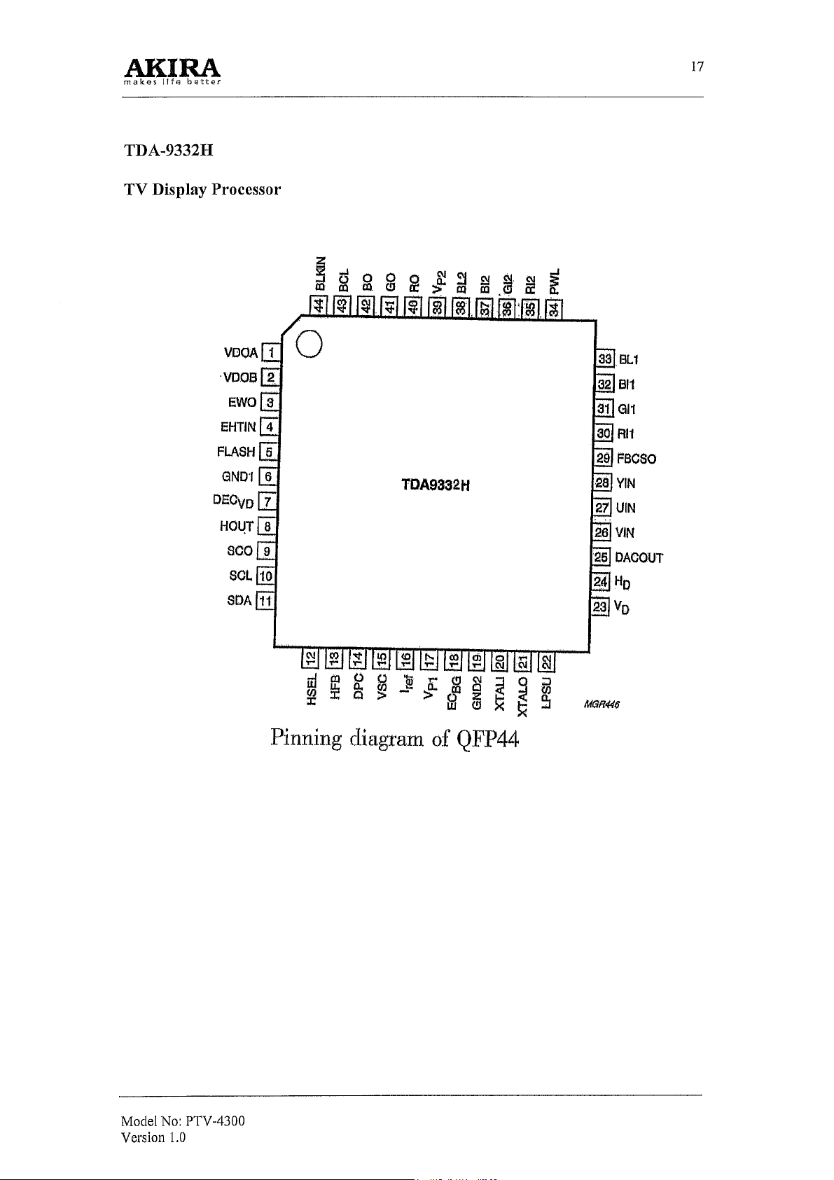
N005 Integrated circuit TDA9332H(2Y)
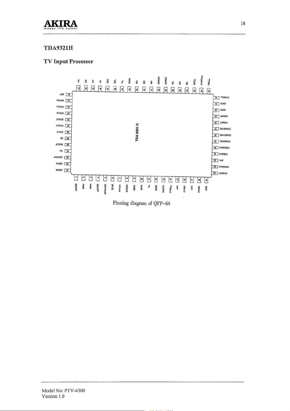
N001 Integrated circuit TDA9321H(2Y)
VD110 Integrated circuit uPC574J(CW574CS)
N011 Integrated circuit AT24C16
N010 Integrated circuit 74HC157N
N007 Integrated circuit HEF4052BP
N008 Integrated circuit 74HCT4538N
N009 Integrated circuit 74HCT4538N
N004 Integrated circuit TDA9178
N834 Integrated circuit SI-3090CA
R411 Carbon film resistor RT13-0.166W-56 Ohm J
R373 Carbon film resistor RT13-0.166W-100 Ohm J
R374 Carbon film resistor RT13-0.166W-100 Ohm J
R484 Carbon film resistor RT13-0.166W-100 Ohm J
R501 Carbon film resistor RT13-0.166W-100 Ohm J
R502 Carbon film resistor RT13-0.166W-100 Ohm J
R503 Carbon film resistor RT13-0.166W-100 Ohm J
R504 Carbon film resistor RT13-0.166W-100 Ohm J
R505 Carbon film resistor RT13-0.166W-100 Ohm J
R506 Carbon film resistor RT13-0.166W-100 Ohm J
R482 Carbon film resistor RT13-0.166W-560 Ohm J
R579 Carbon film resistor RT13-0.166W-680 Ohm J
R565 Carbon film resistor RT13-0.166W- 1.5K Ohm J
R466 Carbon film resistor RT13-0.166W- 1.8K Ohm J
R561 Carbon film resistor RT13-0.166W-5.6K Ohm J
R562 Carbon film resistor RT13-0.166W-5.6K Ohm J
R563 Carbon film resistor RT13-0.166W-5.6K Ohm J
R578 Carbon film resistor RT13-0.166W-5.6K Ohm J
R564 Carbon film resistor RT13-0.166W-1K Ohm J
R317 Carbon film resistor RT13-0.166W-10K Ohm J
R320 Carbon film resistor RT13-0.166W-10K Ohm J
R576 Carbon film resistor RT13-0.166W-18K Ohm J
R577 Carbon film resistor RT13-0.166W- 18K Ohm J
R464 Carbon film resistor RT13-0.166W-27K Ohm J
R473 Carbon film resistor RT13-0.166W-33K Ohm J
R472 Carbon film resistor RT13-0.166W-100K Ohm J
R481 Carbon film resistor RT13-0.166W-270K Ohm J
R399 Carbon film resistor RT13-0.166W-620K Ohm J
R314 Carbon film resistor RT13-0.166W-1M Ohm J
R315 Carbon film resistor RT13-0.166W-1M Ohm J
R508 Carbon film resistor RT14-0.25W-560 Ohm J
Model No: PTV-4300
Version 1.0
43
Page 44

POSITION NAME TYPE
R511 Carbon film resistor RT14-0.25W-560 Ohm J
R515 Carbon film resistor RT14-0.25W-560 Ohm J
R529 Carbon film resistor RT14-0.25W-560 Ohm J
R532 Carbon film resistor RT14-0.25W-560 Ohm J
R536 Carbon film resistor RT14-0.25W-560 Ohm J
R573 Carbon film resistor RT14-0.25W-2.2K Ohm J
R507 Carbon film resistor RT14-0.25W-3.3K Ohm J
R509 Carbon film resistor RT14-0.25W-3.3K Ohm J
R510 Carbon film resistor RT14-0.25W-3.3K Ohm J
R512 Carbon film resistor RT14-0.25W-3.3K Ohm J
R513 Carbon film resistor RT14-0.25W-3.3K Ohm J
R514 Carbon film resistor RT14-0.25W-3.3K Ohm J
R528 Carbon film resistor RT14-0.25W-3.3K Ohm J
R530 Carbon film resistor RT14-0.25W-3.3K Ohm J
R531 Carbon film resistor RT14-0.25W-3.3K Ohm J
R533 Carbon film resistor RT14-0.25W-3.3K Ohm J
R534 Carbon film resistor RT14-0.25W-3.3K Ohm J
R535 Carbon film resistor RT14-0.25W-3.3K Ohm J
R450 Metal oxide film resistor RY21-0.5W-1.2 Ohm J
R429 Metal oxide film resistor RY21-0.5W-56 Ohm J
R549 Metal oxide film resistor RY21-0.5W-100 Ohm J
R550 Metal oxide film resistor RY21-0.5W-100 Ohm J
R559 Metal oxide film resistor RY21-0.5W-100 Ohm J
R560 Metal oxide film resistor RY21-0.5W-100 Ohm J
R461 Metal oxide film resistor RY21-0.5W-1.8K Ohm J
R480 Metal oxide film resistor RY21-0.5W-2.7K Ohm J
R460 Metal oxide film resistor RY21-0.5W-3.3K Ohm J
R382 Metal oxide film resistor RY21-0.5W-10K Ohm J
R471 Metal oxide film resistor RY21-0.5W-10M Ohm J
R370 Metal oxide film resistor RY21-1W-1 Ohm J
R380 Metal oxide film resistor RY21-1W-1 Ohm J
R376 Metal oxide film resistor RY21-1W-1 Ohm J
R377 Metal oxide film resistor RY21-1W-1.2 Ohm J
L410 Metal oxide film resistor RY21-1W-10 Ohm J
R469 Metal oxide film resistor RY21-1W-15 Ohm J
R371 Metal oxide film resistor RY21-1W-33 Ohm J
R415 Metal oxide film resistor RY21-1W-560 Ohm J
R491 Metal oxide film resistor RY21-1W-560 Ohm J
R492 Metal oxide film resistor RY21-1W-560 Ohm J
R493 Metal oxide film resistor RY21-1W-560 Ohm J
R451 Metal oxide film resistor RJ20-1W-51K Ohm J
R553 Fusing resistor PRF5000F008
R556 Fusing resistor PRF5000F008
R470 Fusing resistor RF11-2W-1 Ohm J
R381 Metal oxide film resistor RY21-2W-2.2 Ohm J
R463 Metal oxide film resistor RY21-2W-2.2 Ohm J
R519 Metal oxide film resistor RY21-2W-2.2 Ohm J
R522 Metal oxide film resistor RY21-2W-2.2 Ohm J
R525 Metal oxide film resistor RY21-2W-2.2 Ohm J
R537 Metal oxide film resistor RY21-2W-2.2 Ohm J
R540 Metal oxide film resistor RY21-2W-2.2 Ohm J
R543 Metal oxide film resistor RY21-2W-2.2 Ohm J
R571 Metal oxide film resistor RY21-2W-47 Ohm J
Model No: PTV-4300
Version 1.0
44
Page 45

POSITION NAME TYPE
R571A Metal oxide film resistor RY21-2W-47 Ohm J
R378 Metal oxide film resistor RY21-2W-110 Ohm J
R516 Metal oxide film resistor RY21-2W-110 Ohm J
R517 Metal oxide film resistor RY21-2W-110 Ohm J
R518 Metal oxide film resistor RY21-2W-110 Ohm J
R546 Metal oxide film resistor RY21-2W-110 Ohm J
R547 Metal oxide film resistor RY21-2W-110 Ohm J
R548 Metal oxide film resistor RY21-2W-110 Ohm J
R441 Metal oxide film resistor RY21-2W-560 Ohm J
R442 Metal oxide film resistor RJ20-2W-10K Ohm J
R417 Wire-wound resistor RXG6-H2-5W-100 Ohm J
C503 Ceramic capacitor CC1-63V-06a-SL-22PFJ
C509 Ceramic capacitor CC1-63V-06a-SL-22PFJ
C515 Ceramic capacitor CC1-63V-06a-SL-22PFJ
C521 Ceramic capacitor CC1-63V-06a-SL-22PFJ
C528 Ceramic capacitor CC1-63V-06a-SL-22PFJ
C545 Ceramic capacitor CC1-63V-06a-SL-22PFJ
C501 Ceramic capacitor CC1-63V-06a-SL-100PFJ
C504 Ceramic capacitor CC1-63V-06a-SL-100PFJ
C510 Ceramic capacitor CC1-63V-06a-SL-100PFJ
C519 Ceramic capacitor CC1-63V-06a-SL-100PFJ
C522 Ceramic capacitor CC1-63V-06a-SL-100PFJ
C547 Ceramic capacitor CC1-63V-06a-SL-100PFJ
C502 Ceramic capacitor CC1-63V-12a-SL-680PFJ
C508 Ceramic capacitor CC1-63V-12a-SL-680PFJ
C516 Ceramic capacitor CC1-63V-12a-SL-680PFJ
C520 Ceramic capacitor CC1-63V-12a-SL-680PFJ
C529 Ceramic capacitor CC1-63V-12a-SL-680PFJ
C546 Ceramic capacitor CC1-63V-12a-SL-680PFJ
C375 Ceramic capacitor CT1-63V-06a-2B4-1000PFZ
C376 Ceramic capacitor CT1-63V-06a-2B4-1000PFZ
C377 Ceramic capacitor CT1-63V-06a-2B4-1000PFZ
C378 Ceramic capacitor CT1-63V-08a-2F4-10nFZ
C417 Ceramic capacitor CT1-500V-06c-2B4-390PFK
C383 Ceramic capacitor CT1-500V-06c-2B4-470PFK
C384 Ceramic capacitor CT1-500V-06c-2B4-470PFK
C497 Ceramic capacitor CT1-500V-06c-2B4-470PFK
C413 Ceramic capacitor CT1-500V-12c-2B4-3300PFK
C463 Ceramic capacitor CT1-500V-14c-2B4-3900PFK
C499 Ceramic capacitor CT81-2KV-08c-2B4-220PFK
C410 Ceramic capacitor CT81-2KV-12c-2C1-680PFK
C495 Ceramic capacitor CT81-2KV-12c-2C1-680PFK
C496 Ceramic capacitor CT81-2KV-12c-2C1-680PFK
C478 Ceramic capacitor CT81-2KV-12c-2R4-1500PFK
C532 Polyester film capacitor CL21X-50V-0.01uFJ
C533 Polyester film capacitor CL21X-50V-0.01uFJ
C537 Polyester film capacitor CL21X-50V-0.01uFJ
C539 Polyester film capacitor CL21X-50V-0.01uFJ
C541 Polyester film capacitor CL21X-50V-0.01uFJ
C401 Polyester film capacitor CL21X-50V-0.022uFJ
C316 Polyester film capacitor CL21X-50V-0.039uFJ
C372 Polyester film capacitor CL21X-50V-0.1uFJ
C374 Polyester film capacitor CL21X-50V-0.1uFJ
Model No: PTV-4300
Version 1.0
45
Page 46

POSITION NAME TYPE
C512 Polyester film capacitor CL21X-50V-0.1uFJ
C514 Polyester film capacitor CL21X-50V-0.1uFJ
C517 Polyester film capacitor CL21X-50V-0.1uFJ
C518 Polyester film capacitor CL21X-50V-0.1uFJ
C527 Polyester film capacitor CL21X-50V-0.1uFJ
C530 Polyester film capacitor CL21X-50V-0.1uFJ
C531 Polyester film capacitor CL21X-50V-0.1uFJ
C542 Polyester film capacitor CL21X-50V-0.1uFJ
C548 Polyester film capacitor CL21X-50V-0.1uFJ
C320 Polyester film capacitor CL21X-50V-0.27uFJ
C381 Polyester film capacitor CL12-100V-0.047uFJ
C445 Polypropylene capacitor CBB 13-200V-0.047uFJ
C451 Polypropylene capacitor CBB 13-400V-0.033uFJ
C423 Polypropylene capacitor CBB 13-400V-0.033uFJ
C442 Polypropylene capacitor CBB 13-400V-0.12uFJ
C443 Polypropylene capacitor CBB 13-400V-0.12uFJ
C450 Polypropylene capacitor CBB 13-400V-0.3uFJ
C466 Polypropylene capacitor CBB 13-630V-8200PFJ
C400 Polypropylene capacitor CF99M4Z102KB
C440 Polypropylene capacitor CBB81-1.6KV-1500PFJ
C461 Polypropylene capacitor CBB81-1.6KV-1500PFJ
C439 Polypropylene capacitor CBB81-1.6KV-2400PFJ
C444 Polypropylene capacitor CBB81-1.6KV-3000PFJ
C477 Aluminium electrolytic capacitor CD 110X-16V-47uFM
C540 Aluminium electrolytic capacitor CD 110X-16V-47uFM
C371 Aluminium electrolytic capacitor CD 110X-35V-100uFM
C386 Aluminium electrolytic capacitor CD 110X-35V-100uFM
C416 Aluminium electrolytic capacitor CD 110X-35V-100uFM
C559 Aluminium electrolytic capacitor CD 110X-35V-100uFM
C385 Aluminium electrolytic capacitor CD 288H-35V-2200uFQ
C544 Aluminium electrolytic capacitor CD 110-16V-10uFM
C560 Aluminium electrolytic capacitor CD 110-50V-0.47uFM
C535 Aluminium electrolytic capacitor CD 110-50V-47uFM
C538 Aluminium electrolytic capacitor CD 110-50V-47uFM
C534 Aluminium electrolytic capacitor CD 110X-50V-100uFM
C536 Aluminium electrolytic capacitor CD 110X-50V-100uFM
C460 Aluminium electrolytic capacitor CD 110X-50V-330uFM
C555 Aluminium electrolytic capacitor CD 110-63V-10uFM
C556 Aluminium electrolytic capacitor CD 110-63V-10uFM
C557 Aluminium electrolytic capacitor CD 110-63V-10uFM
C558 Aluminium electrolytic capacitor CD 110-63V-10uFM
C373 Aluminium electrolytic capacitor CD 110X-100V-47uFM
C464 Aluminium electrolytic capacitor CDS-100V-10uFM
C382 Aluminium electrolytic capacitor CD110-100V-330uFM
C448 Aluminium electrolytic capacitor CD288H-160V-33uFM
C446 Aluminium electrolytic capacitor CD81-250V-33uFM
L381 Fixed inductor LGB0606-33uHJ
L442 Fixed inductor TLN3329 (JUB4.757.003)
L461 Fixed inductor TLN3329 (JUB4.757.004)
L401 Cored inductor TEM2011
L402 Cored inductor TEM2011
Model No: PTV-4300
Version 1.0
46
Page 47

POSITION NAME TYPE
L403 Cored inductor TEM2011
L404 Cored inductor TEM2011
L449 Cored inductor TEM2011
L470 Cored inductor TEM2011
L501 Cored inductor TEM2011
L502 Cored inductor TEM2011
L503 Cored inductor TEM2011
L504 Cored inductor TEM2011
L505 Cored inductor TEM2011
L506 Cored inductor TEM2011
L441 Horizontal linear coil HXT10 (JUB4.756.016, DP5188)
L441 Horizontal linear coil HXT15 (JUB4.756.021, DP4388)
L443 Horizontal amplitude inductor LGT-30uH (JUB4.757.037)
VD306 Diode 2CK75D (1N4148)
VD463 Diode 2CK75D (1N4148)
VD502 Diode 2CK75D (1N4148)
VD503 Diode 2CK75D (1N4148)
VD504 Diode 2CK75D (1N4148)
VD506 Diode 2CK75D (1N4148)
VD510 Diode 2CK75D (1N4148)
VD450 Diode 1S1887
VD467 Diode 2SC1887
VD487 Diode 2SC1887
VD488 Diode 2SC1887
VD370 Diode EU2A
VD371 Diode EU2A
VD406 Diode 2CZRU2
VD460 Diode TVR-1B
VD465 Diode W05Z3.6B
VD466 Diode W05Z3.6B
VD468 Diode W05Z3.6B
VD507 Diode W05Z6.2B
VD508 Diode W05Z6.2B
YD464 Diode W05Z11B
VD509 Diode W05Z11B
VD505 Diode W05Z24C
VD489 Diode W05Z30B
VD461 Diode ERC20-06
VD404 Diode 5VUZ52
V402 Transistor 2SC2235-0
V501 Transistor 2SA1015-Y
V502A Transistor 2SA1015-Y
V461 Transistor 2SC1815-Y
V462 Transistor 2SC1815-Y
V504 Transistor 2SCI 815-Y
V505 Transistor 2SC1815-Y
V460 Transistor 2SB688 (3CA688)
V502 Transistor 2SC3852
V525 Transistor 2SC4686A
V404 Transistor 2SC5144
N503 Integrated Circuit L7805CV (MC7805CT)
N502 Integrated Circuit L7812CV (MC7812CT)
Model No: PTV-4300
Version 1.0
47
Page 48

POSITION NAME TYPE
N501 Integrated Circuit L7912CV
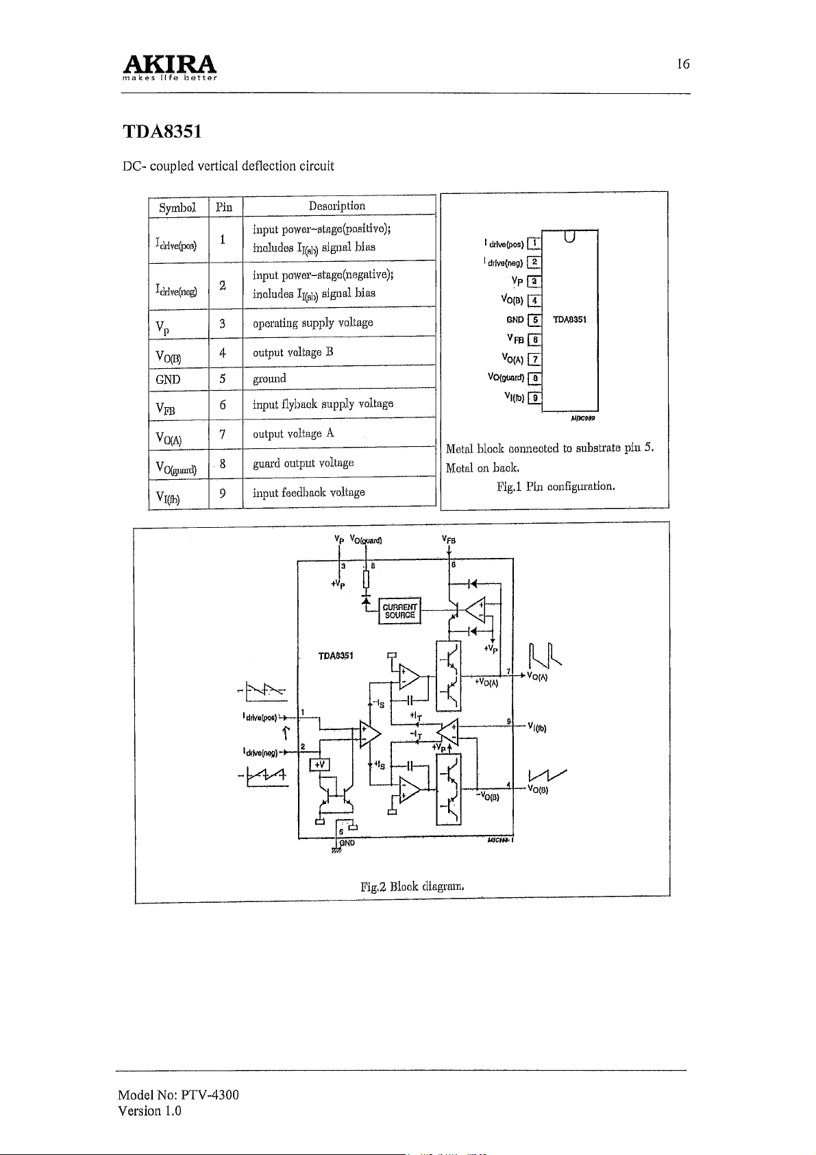
N301 Integrated Circuit TDA8351
N504 Integrated Circuit STK392-040
N505 Integrated Circuit STK392-040
T461 Flyback transformer BSC70D1
T401 Line-driving transformer BCT-7
T400 Dynamic focus transformer TLN2168
N511 High tension box TPA6032AH
R846 Carbon film resistor RT13-0.166W-220 Ohm J
R817 Carbon film resistor RT13-0.166W-680 Ohm J
R827 Carbon film resistor RT13-0.166W- 1K Ohm J
R880 Carbon film resistor RT13-0.166W-IK Ohm J
R823 Carbon film resistor RT13-0.166W-2.7K Ohm J
R830 Carbon film resistor RT13-0.166W-470 Ohm J
R822 Carbon film resistor RT13-0.166W-3.9K Ohm J
R834 Carbon film resistor RT13-0.166W-5.6K Ohm J
R846A Carbon film resistor RT13-0.166W-5.6K Ohm J
R881 Carbon film resistor RT13-0.166W-5.6K Ohm J
R837 Carbon film resistor RT13-0.166W-6.8K Ohm J
R838 Carbon film resistor RT13-0.166W-6.8K Ohm J
R847A Carbon film resistor RT13-0.166W-10K Ohm J
R820 Carbon film resistor RT13-0.166W-220K Ohm J
R819 Metal oxide film resistor RY21-0.5W-10 Ohm J
R815 Metal oxide film resistor RY21-0.5W-3.3K Ohm J
R832 Metal oxide film resistor RY21-0.5W-56K Ohm J
R813 Glass enamel film resistor RI40-0.5W-1.5M Ohm J
R833 Metal oxide film resistor RJ20-1W-0.47 Ohm J
R831 Metal oxide film resistor RJ20-1W-15K Ohm J
RF852 Metal oxide film resistor RY21-2W-0.12 Ohm J
RF856 Metal oxide film resistor RY21-2W-0.12 Ohm J
R818 Metal oxide film resistor RY21-2W-0.12 Ohm J
R821 Metal oxide film resistor RY21-2W-0.12 Ohm J
R832A Metal oxide film resistor RY21-2W-2.2 Ohm J
R825 Metal oxide film resistor RY21-2W-47 Ohm J
R816 Metal oxide film resistor RY21-2W-100K Ohm J
R841 Fusing resistor RF10-0.5W- 12 Ohm J
RS01 Glass enamel film resistor VR37 225J (232224290185)
R899 Glass enamel film resistor VR37 825J
RV899 Piezoresistor TNR15G471K300 (MYG15-471K)
RT812 Thermistor B57237-S479-M
RF872 Metal oxide film resistor RY21-2W-100 Ohm J
RF851 Direct fuse PRF5000F008 (PRF50005491)
RF853 Direct fuse PRF5000F008 (PRF50005491)
RF855 Direct fuse PRF5000F008 (PRF50005491)
C869A Ceramic capacitor CC1-63V-08a-C-100PFJ
C809 Ceramic capacitor CT1-63V-06c-2B4-470PFK
C829 Ceramic capacitor CT1-63V-06a-2B4-1000PFK
C850 Ceramic capacitor CT1-63V-06a-2B4-1000PFK
C831 Ceramic capacitor CT1-63V-08a-2F4-10nPFZ
Model No: PTV-4300
Version 1.0
48
Page 49

POSITION NAME TYPE
C837 Ceramic capacitor CT1-63V-08a-2F4-10nPFZ
C856 Ceramic capacitor CT1-63V-08a-2F4-10nPFZ
C803 Ceramic capacitor DE1107-1E472MAC250
C804 Ceramic capacitor CT1-500V-12c-2E4-4700PFP
C822 Ceramic capacitor DE0910B471K-KX
C823 Ceramic capacitor DE0910B471K-KX
C824 Ceramic capacitor CT7-400VAC-08a-2B4-470PFM
C860 Ceramic capacitor CT1-500V-06c-2B4-470PFK
C861 Ceramic capacitor CT1-500V-06c-2B4-470PFK
C866 Ceramic capacitor CT1-500V-06c-2B4-470PFK
C868 Ceramic capacitor CT1-500V-06c-2B4-470PFK
C870 Ceramic capacitor CT1-500V-06c-2B4-470PFK
C872 Ceramic capacitor CT1-500V-06c-2B4-470PFK
C893 Ceramic capacitor CT81-2KV-08c-2R4-220PFK
C818 Ceramic capacitor CT81-2KV-12c-2C1-1000PFK
C817 Polyester film capacitor CL21X-50V-0.1uFJ
C832 Polyester film capacitor CL21X-50V-0.1uFJ
C834 Polyester film capacitor CL21X-50V-0.1uFJ
C836 Polyester film capacitor CL21X-50V-0.1uFJ
C838 Polyester film capacitor CL21X-50V-0.1uFJ
C843 Polyester film capacitor CL21X-50V-0.1uFJ
C851 Polyester film capacitor CL21X-50V-0.1uFJ
C880 Polyester film capacitor CL21X-50V-0.1uFJ
C801 Polypropylene capacitor CBB62-250VAC-0.22uFK
C802 Polypropylene capacitor CBB62-250VAC-0.22uFK
C825 Polypropylene capacitor CBB13-630V-0.01uFH
C844 Aluminium electrolytic capacitor CD110X-16V-101uFM
C852 Aluminium electrolytic capacitor CD110X-16V-470uFM
C863 Aluminium electrolytic capacitor CD288H-16V-3300uFQ
C833 Aluminium electrolytic capacitor CD110X-25V-470uFM
C862 Aluminium electrolytic capacitor CD110X-100V-470uFM
C841 Aluminium electrolytic capacitor CD81-50V-10uFM
C842 Aluminium electrolytic capacitor CD81-50V-10uFM
C819 Aluminium electrolytic capacitor CD110X-50V-100uFM
C835 Aluminium electrolytic capacitor CD81-50V-330uFM
C869 Aluminium electrolytic capacitor CD81-50V-330uFM
C871 Aluminium electrolytic capacitor CD81-50V-330uFM
C873 Aluminium electrolytic capacitor CD81-50V-330uFM
C867 Aluminium electrolytic capacitor CD288H-50V-2200uFQ
C884 Aluminium electrolytic capacitor CD289H-160V-330uFT
C820 Aluminium electrolytic capacitor CD289-450V-820uFM
L812 Cored inductor TEM2011
L814 Cored inductor TEM2011
L816 Cored inductor TEM2011
L860 Cored inductor TEM2011
L861 Cored inductor TEM2011
L866 Cored inductor TEM2011
L868 Cored inductor TEM2011
L869 Cored inductor TEM2011
L871 Cored inductor TEM2011
L862 Fixed inductor TLN2026-11uHK
L863 Fixed inductor TLN2026-11uHK
Model No: PTV-4300
Version 1.0
49
Page 50

POSITION NAME TYPE
L867 Fixed inductor TLN2026-11uHK
L870 Fixed inductor TLN2026-11uHK
L876 Fixed inductor TLN2026-11uHK
L883 Fixed inductor TRF9253D- 1.luHK
L885 Fixed inductor TLN3155D-100uHK
VD831A Diode 2CK75D (1N4148)
VD834 Diode 2CK75D
VD835 Diode 2CK75D
VD836 Diode 2CK75D
VD880 Diode W05Z6.8B
VD850 Diode W05Z9.1B
VD817 Diode W05Z12A
VD819 Diode W05Z12A
VD831 Diode W05Z12C
VD812 Diode W05Z18C
VD821 Diode W05Z1812
VD810 Diode W05Z22C
VD832 Diode W05Z24C
VD818 Diode W05Z30B
VD809 Diode AU01Z
VD813 Diode AU01Z
VD822 Diode AU01Z
VD823 Diode AK03
VD861 Diode RU4A (LF-L1)
VD866 Diode RU4AM (LF-L1)
VD863 Diode EU2A
VD815 Diode SARS01
VD864 Diode FML-G12S
VD865 Diode FML-G12S
VD867 Diode FML-G12S
VD893 Diode FML-G16S
V802 Transistor 2SC2655-Y(C)
V806 Transistor 2SC1815-Y
V809 Transistor 2SC1815-Y
V882 Transistor 2SC1815-Y
V883A Transistor 2SC1815-Y
V807 Transistor 2SC3852
V880 Transistor 2SC3852
V881 Transistor 2SC3852
V883 Transistor 2SC3852
F801 Delay fuse RT1-20-5A-250V
F802 Delay fuse RT1-20-5A-250V
T801 Filter line TRF3173 (LCL-F11)
T802 Filter line TRF3197 (LCL-F12)
T862 Transformer switch BCK-25502L (JUB4.726.052)
N803 Integrated Circuit L7805CV; MC7805CT
N801 Integrated Circuit STR-F6658B
VQ805 Integrated Circuit SE125N
N804 Photo coupler TLP621GR; HS817
VC801 Gretz rectifier RBV-606, LFA; D6SB60L
Model No: PTV-4300
Version 1.0
50
Page 51

POSITION NAME TYPE
R964 Carbon film resistor RT13-0.166W-33 Ohm J
R913 Carbon film resistor RT13-0.166W-47 Ohm J
R971 Carbon film resistor RT13-0.166W-47 Ohm J
R337 Carbon film resistor RT13-0.166W-75 Ohm J
R338 Carbon film resistor RT13-0.166W-75 Ohm J
R339 Carbon film resistor RT13-0.166W-75 Ohm J
R914 Carbon film resistor RT13-0.166W-75 Ohm J
R915 Carbon film resistor RT13-0.166W-75 Ohm J
R913 Carbon film resistor RT13-0.166W-75 Ohm J
R934 Carbon film resistor RT13-0.166W-75 Ohm J
R943 Carbon film resistor RT13-0.166W-75 Ohm J
R945 Carbon film resistor RT13-0.166W-75 Ohm J
R973 Carbon film resistor RT13-0.166W-75 Ohm J
R333 Carbon film resistor RT13-0.166W-100 Ohm J
R334 Carbon film resistor RT13-0.166W-100 Ohm J
R335 Carbon film resistor RT13-0.166W-100 Ohm J
R336 Carbon film resistor RT13-0.166W-100 Ohm J
R340 Carbon film resistor RT13-0.166W-100 Ohm J
R905 Carbon film resistor RT13-0.166W-100 Ohm J
R906 Carbon film resistor RT13-0.166W-100 Ohm J
R907 Carbon film resistor RT13-0.166W-100 Ohm J
R908 Carbon film resistor RT13-0.166W-100 Ohm J
R946 Carbon film resistor RT13-0.166W-100 Ohm J
R972 Carbon film resistor RT13-0.166W-100 Ohm J
R935 Carbon film resistor RT13-0.166W-180 Ohm J
R967 Carbon film resistor RT13-0.166W-330 Ohm J
R970 Carbon film resistor RT13-0.166W-330 Ohm J
R966 Carbon film resistor ItT13-0.166W-680 Ohm J
R969 Carbon film resistor RT13-0.166W-750 Ohm J
R909 Carbon film resistor RT13-0.166W- 1K Ohm J
R910 Carbon film resistor RT13-0.166W- 1K Ohm J
R911 Carbon film resistor RT13-0.166W- 1K Ohm J
R912 Carbon film resistor RT13-0.166W- 1K Ohm J
R923 Carbon film resistor RT13-0.166W- 1K Ohm J
R925 Carbon film resistor RT13-0.166W- 1K Ohm J
R936 Carbon film resistor RT13-0.166W- 1K Ohm J
R938 Carbon film resistor RT13-0.166W- 1K Ohm J
R951 Carbon film resistor RT13-0.166W- 1K Ohm J
R954 Carbon film resistor RT13-0.166W- 1K Ohm J
R341 Carbon film resistor RT13-0.155W-2.2K Ohm J
R342 Carbon film resistor RT13-0.155W-2.2K Ohm J
R346 Carbon film resistor RT13-0.155W-2.2K Ohm J
R347 Carbon film resistor RT13-0.155W-2.2K Ohm J
R937 Carbon film resistor RT13-0.155W-2.2K Ohm J
R939 Carbon film resistor RT13-0.155W-2.2K Ohm J
R903 Carbon film resistor RT13-0.155W-2.7K Ohm J
R904 Carbon film resistor RT13-0.155W-2.7K Ohm J
R927 Carbon film resistor RT13-0.155W-4.7K Ohm J
R928 Carbon film resistor RT13-0.155W-4.7K Ohm J
R949 Carbon film resistor RT13-0.155W-4.7K Ohm J
R974 Carbon film resistor RT13-0.166W-5.1K Ohm J
R975 Carbon film resistor RT13-0.165W-5.1K Ohm J
R959 Carbon film resistor RT13-0.166W-5.6K Ohm J
Model No: PTV-4300
Version 1.0
51
Page 52

POSITION NAME TYPE
R921 Carbon film resistor RT13-0.165W-9.1K Ohm J
R922 Carbon film resistor RT13-0.165W-10K Ohm J
R929 Carbon film resistor RT13-0.165W-10K Ohm J
R930 Carbon film resistor RT13-0.165W-10K Ohm J
R947 Carbon film resistor RT13-0.165W-10K Ohm J
R957 Carbon film resistor RT13-0.166W-18K Ohm J
R958 Carbon film resistor RT13-0.166W-18K Ohm J
R901 Carbon film resistor RT13-0.166W-22K Ohm J
R902 Carbon film resistor RT13-0.166W-18K Ohm J
R932 Carbon film resistor RT13-0.166W-18K Ohm J
R941 Carbon film resistor RT13-0.166W-18K Ohm J
R942 Carbon film resistor RT13-0.166W-18K Ohm J
R924 Carbon film resistor RT13-0.166W-30K Ohm J
R926 Carbon film resistor RT13-0.166W-39K Ohm J
R933 Carbon film resistor RT13-0.166W-47K Ohm J
R952 Carbon film resistor RT13-0.166W-47K Ohm J
R962 Carbon film resistor RT13-0.166W-47K Ohm J
R963 Carbon film resistor RT13-0.166W-47K Ohm J
R332 Carbon film resistor RT13-0.166W-100K Ohm J
R916 Carbon film resistor RT13-0.166W-100K Ohm J
R917 Carbon film resistor RT13-0.166W-100K Ohm J
R918 Carbon film resistor RT13-0.166W-100K Ohm J
R919 Carbon film resistor RT13-0.166W-100K Ohm J
R940 Carbon film resistor RT13-0.166W-100K Ohm J
R944 Carbon film resistor RT13-0.166W-100K Ohm J
R948 Carbon film resistor RT13-0.166W-100K Ohm J
R953 Carbon film resistor RT13-0.166W-100K Ohm J
R960 Carbon film resistor RT13-0.166W-100K Ohm J
R961 Carbon film resistor RT13-0.166W-100K Ohm J
R965 Carbon film resistor RT13-0.166W-100K Ohm J
R968 Carbon film resistor RT13-0.166W-100K Ohm J
R976 Carbon film resistor RT13-0.166W-150K Ohm J
R977 Carbon film resistor RT13-0.166W-150K Ohm J
R331 Carbon film resistor RT13-0.166W-1M Ohm J
R931 Carbon film resistor RT14-0.25W- 100 Ohm J
R950 Carbon film resistor RT13-0.166W-4.7K Ohm J
R920 Metal oxide film resistor RY21-0.5W- 100 Ohm J
C335 Ceramic capacitor CC1-63V-06a-SL-27PFJ
C336 Ceramic capacitor CC1-63V-06a-SL-27PFJ
C337 Ceramic capacitor CC1-63V-06a-SL-27PFJ
C338 Ceramic capacitor CC1-63V-06a-SL-27PFJ
C339 Ceramic capacitor CC1-63V-06a-SL-27PFJ
C930 Ceramic capacitor CT1-63V-06a-2B4-1000PFK
C934 Ceramic capacitor CT1-63V-06a-2B4-1000PFK
C944 Ceramic capacitor CT1-63V-06a-2B4-1000PFK
C951 Ceramic capacitor CT1-63V-06a-2B4-1000PFK
C905 Ceramic capacitor CT1-63V-06a-2B4-1200PFK
C903 Ceramic capacitor CT1-63V-10a-2B4-4700PFK
C906 Ceramic capacitor CT1-63V-12e-2B4-5600PFK
C919 Ceramic capacitor CT1-63V-12e-2B4-5600PFK
C920 Ceramic capacitor CT1-63V-12e-2B4-5600PFK
C936 Ceramic capacitor CTl-63V-08a-2F4-10nFZ
Model No: PTV-4300
Version 1.0
52
Page 53

POSITION NAME TYPE
C964 Ceramic capacitor CT1-63V-08a-2F4-10nFZ
C965 Ceramic capacitor CT1-63V-08a-2F4-10nFZ
C916 Polytster film capacitor CL11X-50V-0.018uFJ
C918 Polytster film capacitor CL11X-50V-0.018uFJ
C901 Polytster film capacitor CL21X-50V-0.022uFJ
C902 Polytster film capacitor CL21X-50V-0.022uFJ
C915 Polytster film capacitor CL21X-50V-0.022uFJ
C917 Polytster film capacitor CL21X-50V-0.022uFJ
C938 Polytster film capacitor CL21X-50V-0.022uFJ
C960 Polytster film capacitor CL21X-50V-0.022uFJ
C962 Polytster film capacitor CL21X-50V-0.022uFJ
C963 Polytster film capacitor CL21X-50V-0.022uFJ
C331 Polytster film capacitor CL21X-50V-0.1uFJ
C332 Polytster film capacitor CL21X-50V-0.1uFJ
C333 Polytster film capacitor CL21X-50V-0.1uFJ
C904 Polytster film capacitor CL21X-50V-0.1uFJ
C911 Polytster film capacitor CL21X-50V-0.1uFJ
C912 Polytster film capacitor CL21X-50V-0.1uFJ
C913 Polytster film capacitor CL21X-50V-0.1uFJ
C914 Polytster film capacitor CL21X-50V-0.1uFJ
C929 Polytster film capacitor CL21X-50V-0.1uFJ
C932 Polytster film capacitor CL21X-50V-0.1uFJ
C933 Polytster film capacitor CL21X-50V-0.1uFJ
C950 Polytster film capacitor CL21X-50V-0.1uFJ
C952 Polytster film capacitor CL21X-50V-0.1uFJ
C953 Polytster film capacitor CL21X-50V-0.1uFJ
C958 Polytster film capacitor CL21X-50V-0.1uFJ
C959 Polytster film capacitor CL21X-50V-0.1uFJ
C939 Polytster film capacitor CL21X-50V-0.22uFJ
C907 Polytster film capacitor CL21X-50V-0.68uFJ
C908 Aluminium electrolytic capacitor CD 110-50V-2.2uFM
C909 Aluminium electrolytic capacitor CD 110-50V-2.2uFM
C910 Aluminium electrolytic capacitor CD 110-50V-2.2uFM
C945 Aluminium electrolytic capacitor CD 110-50V-2.2uFM
C946 Aluminium electrolytic capacitor CD 110-50V-2.2uFM
C940 Aluminium electrolytic capacitor CD 110-16V-4.7uFM
C941 Aluminium electrolytic capacitor CD 110-16V-4.7uFM
C921 Aluminium electrolytic capacitor CD 110-16V-10uFM
C922 Aluminium electrolytic capacitor CD 110-16V-10uFM
C923 Aluminium electrolytic capacitor CD 110-16V-10uFM
C924 Aluminium electrolytic capacitor CD 110-16V-10uFM
C926 Aluminium electrolytic capacitor CD 110-16V-10uFM
C927 Aluminium electrolytic capacitor CD 110-16V-10uFM
C947 Aluminium electrolytic capacitor CD 110-16V-10uFM
C948 Aluminium electrolytic capacitor CD 110-16V-10uFM
C949 Aluminium electrolytic capacitor CD 110-16V-10uFM
C955 Aluminium electrolytic capacitor CD 110-16V-10uFM
C956 Aluminium electrolytic capacitor CD 110-16V-10uFM
C957 Aluminium electrolytic capacitor CD 110-16V-10uFM
C925 Aluminium electrolytic capacitor CD 110-16V-22uFM
C334 Aluminium electrolytic capacitor CD 110X-16V-47uFM
C928 Aluminium electrolytic capacitor CD 110X-16V-47uFM
C931 Aluminium electrolytic capacitor CD 110X-16V-47uFM
Model No: PTV-4300
Version 1.0
53
Page 54

POSITION NAME TYPE
C943 Aluminium electrolytic capacitor CD 110X-16V-47u FM
C937 Aluminium electrolytic capacitor CD 110X-16V-220uFM
C935 Aluminium electrolytic capacitor CD 110X-16V-470uFM
C942 Aluminium electrolytic capacitor CD 110X-16V-470uFM
C961 Aluminium electrolytic capacitor CD 110X-35V-220uFM
C336A Aluminium electrolytic capacitor CD 110X-50V-10uFM
C340A Aluminium electrolytic capacitor CD 110X-50V-10uFM
L910 Fixed inductor TGB0606-15uHK
L908 Fixed inductor TGB0606-15uHK
L90! Cored inductor TEM2028K
L902 Cored inductor TEM2028K
L903 Cored inductor TEM2028K
L904 Cored inductor TEM2028K
L905 Cored inductor TEM2028K
L906 Cored inductor TEM2028K
L907 Cored inductor TEM2028K
L909 Cored inductor TEM2028K
VD331 Diode W05Z5.1B
VD332 Diode W05Z5.1B
VD903 Diode W05ZS.6B
VD901 Diode W05Z6.2B
VD902 Diode W05Z6.2B
VD904 Diode W05Z6.2B
VD905 Diode W05Z6.2B
VD906 Diode W05Z6.2B
V904 Transistor 2SC2878-A
V905 Transistor 2SC2878-A
V901 Transistor 2SC1815-Y (3DG 1815-Y)
V902 Transistor 2SC1815-Y (3DG1815-Y)
V903 Transistor 2SC1815-Y (3DG1815-Y)
V906 Transistor 2SC1815-Y (3DG1815-Y)
V907 Transistor 2SC1815-Y (3DG1815-Y)
V908 Transistor 2SC1815-Y (3DG1815-Y)
V909 Transistor 2SC1815-Y (3DG1815-Y)
V910 Transistor 2SC1815-Y (3DG1815-Y)
V911 Transistor 2SC1815-Y (3DG1815-Y)
N300 Integrated Circuit 74HCT86N
N902 Integrated Circuit M5218AP
N903 Integrated Circuit HCF4066BE (MC14066BCP)
N901 Integrated Circuit TDA7429S
PV01 AV jack AV-3S-9PBYUV
PV02 AV jack AV-1-3PK100
PV03 AV jack AV-VGA-2PA
RGY15 Carbon film resistor RT13-0.166W-2.7 Ohm J
RGY17 Carbon film resistor RT13-0.166W-2.7 Ohm J
RGY14 Carbon film resistor RT13-0.166W-18 Ohm J
RGY16 Carbon film resistor RT13-0.166W-18 Ohm J
Model No: PTV-4300
Version 1.0
54
Page 55

POSITION NAME TYPE
RG35 Carbon film resistor RT13-0.166W-56 Ohm J
RG36 Carbon film resistor RT13-0.166W-56 Ohm J
RG14 Carbon film resistor RT13-0.166W- 100 Ohm J
RGY27 Carbon film resistor RT13-0.166W- 100 Ohm J
RGY28 Carbon film resistor RT13-0.166W- 100 Ohm J
RGY31 Carbon film resistor RT13-0.166W-470 Ohm J
RGY21 Carbon film resistor RT13-0.166W-680 Ohm J
RGY23 Carbon film resistor RT13-0.166W-680 Ohm J
RG08 Carbon film resistor RT13-0.166W-1K Ohm J
RGY07 Carbon film resistor RT13-0.166W-1.2K Ohm J
RGY09 Carbon film resistor RT13-0.166W-1.2K Ohm J
RGY34 Carbon film resistor RT13-0.166W-1.2K Ohm J
RG02 Carbon film resistor RT13-0.166W-1.5K Ohm J
RG06 Carbon film resistor RT13-0.166W-1.5K Ohm J
RGY06 Carbon film resistor RT13-0.166W-1.5K Ohm J
RGY08 Carbon film resistor RT13-0.166W-1.5K Ohm J
RGY20 Carbon film resistor RT13-0.166W-2.2K Ohm J
RGY22 Carbon film resistor RT13-0.166W-2.2K Ohm J
RGY26 Carbon film resistor RT13-0.166W-2.2K Ohm J
RGY29 Carbon film resistor RT13-0.166W-2.2K Ohm J
RGY32 Carbon film resistor RT13-0.166W-3.3K Ohm J
RG39 Carbon film resistor RT13-0.166W-3.6K Ohm J
RGY33 Carbon film resistor RT13-0.166W-9.1K Ohm J
RG38 Carbon film resistor RT13-0.166W-10K Ohm J
RGY13 Carbon film resistor RT13-0.166W-12K Ohm J
RG11 Carbon film resistor RT13-0.166W-68K Ohm J
RGY10 Carbon film resistor RT13-0.166W-68K Ohm J
RGY11 Carbon film resistor RT13-0.166W-68K Ohm J
RGY24 Carbon film resistor RT13-0.166W-1M Ohm J
RGY30 Metal oxide film resistor RY21-1W-10 Ohm J
RG20 Metal oxide film resistor RY21-1W-33 Ohm J
RGY18 Metal oxide film resistor RY21-2W-470 Ohm J
RGY01 Metal oxide film resistor RY21-2W-470 Ohm J
RG17 Glass enamel film resistor RI40-0.5W-1.5K Ohm K
CG02 Ceramic capacitor CC1-63V-06a-C-12PFJ
CG14 Ceramic capacitor CT1-500V-06c-2B4-560PFK
CGY04 Ceramic capacitor CT1-500V-14c-2B4-4700PFK
CGY06 Ceramic capacitor CT1-500V-14c-2B4-4700PFK
CG08 Polytster film capacitor CL21X-50V-0.022uFJ
CG05 Polytster film capacitor CL21X-50V-0.1uFJ
CGY 13 Polytster film capacitor CL21X-50V-0.1uFJ
CG11 Polytster film capacitor CL21X-250V-0.1uFJ
CGY01 Polypropylene capacitor CBB81-1.6KV- 1800PFJ
CG30 Aluminium electrolytic capacitor CD110X-16V-10uFM
CG26 Aluminium electrolytic capacitor CD110X-I 6V-470uFM
CG27 Aluminium electrolytic capacitor CD110X-25V-100uFM
CGY12 Aluminium electrolytic capacitor CD110X-25V-100uFM
CGY11 Aluminium electrolytic capacitor CD110X-35V-220uFM
CG28 Aluminium electrolytic capacitor CD110-50V-0.47uFM
CGY03 Aluminium electrolytic capacitor CD110X-50V-47uFM
CGY08 Aluminium electrolytic capacitor CD110X-50V-47uFM
CGY14 Aluminium electrolytic capacitor CD110X-50V-47uFM
CG29 Aluminium electrolytic capacitor CD288H-250V-33uFQ
Model No: PTV-4300
Version 1.0
55
Page 56

POSITION NAME TYPE
CGY02 Aluminium electrolytic capacitor CD288-250V-10uFQ
CGY10 Aluminium electrolytic capacitor CD288-250V-10uFQ
LGY18 Fixed inductor LGB0606-0.33uHJ
LGY01 Cored inductor TEM2011
LGY02 Cored inductor TEM2011
LGY05 Cored inductor TEM2011
VDG02 Diode 1N4148 (2CK75D)
VDGY03 Diode 1N4148 (2CK75D)
VDGY04 Diode 1N4148 (2CK75D)
VDG08 Diode 1N4148 (2CK75D)
VDG10 Diode 1N4148 (2CK75D)
VDGYI0 Diode 1N4148 (2CK75D)
VDGY12 Diode 1N4148 (2CK75D)
VDGY16 Diode 1N4148 (2CK75D)
VDG14 Diode MTZJ13A (W05Z 13A)
VDG18 Diode BAV21
VG05 Transistor 2SC1815-Y (3DG1815-Y)
VGY11 Transistor 2SC1815-Y (3DG1815-Y)
VGY12 Transistor 2SC1815-Y (3DG1815-Y)
VGY14 Transistor 2SC1815-Y (3DG1815-Y)
VGY10 Transistor 2SA1015-Y (3CG1015-Y)
VGY13 Transistor 2SA1015-Y (3CG1015-Y)
VGY03 Transistor 2SA1837
VGY04 Transistor 2SC4793
NG02 Integrated circuit TDA6111Q
SG01 GZS CRT socket GZS10-2-108
RB35 Carbon film resistor RT13-0.166W-56 Ohm J
RB36 Carbon film resistor RT13-0.166W-56 Ohm J
RB14 Carbon film resistor RT13-0.166W-100 Ohm J
RB08 Carbon film resistor RT13-0.166W-1K Ohm J
RB02 Carbon film resistor RT13-0.166W- 1.5K Ohm J
RB06 Carbon film resistor RT13-0.166W-l.5K Ohm J
RB40 Carbon film resistor RT13-0.166W-3.6K Ohm J
RB39 Carbon film resistor RT13-0.166W-10K Ohm J
RB11 Carbon film resistor RT13-0.166W-68K Ohm J
RB20 Metal oxide film resistor RY21-1W-33 Ohm J
RB17 Glass enamel film resistor RI40-0.5W- 1.5K Ohm K
CB02 Ceramic capacitor CC1-63V-06a-C-12PFJ
CB14 Ceramic capacitor CTl-500V-06c-2B4-560PFK
CB08 Polytster film capacitor CL21X-50V-0.022uFJ
CB05 Polytster film capacitor CL21X-50V-0.1uFJ
CB11 Polytster film capacitor CL21X-250V-0.1uFJ
CB39 Polypropylene capacitor CBB81-1.6KV-1800PFJ
CB30 Aluminium electrolytic capacitor CD110C-16V-10uFM
CB26 Aluminium electrolytic capacitor CD110X-16V-470uFM
CB27 Aluminium electrolytic capacitor CD110X-25V-100uFM
CB28 Aluminium electrolytic capacitor CD110-50V-0.47luFM
CB29 Aluminium electrolytic capacitor CD288H-250V-33uFQ
Model No: PTV-4300
Version 1.0
56
Page 57

POSITION NAME TYPE
LB01 Cored inductor TEM2011
VDB01 Diode 1N4148 (2CK75D)
VDB08 Diode 1N4148 (2CK75D)
VDB10 Diode 1N4148 (2CK75D)
VDB14 Diode MTZJ13A (W05Z13A)
VDB18 Diode BAV21
VB05 Transistor 2SC1815-Y (3DG1815-Y)
NB02 Integrated circuit TDA6111Q
SB01 GZS CRT socket GZS10-2-108
RR35 Carbon film resistor RT13-0.166W-56 Ohm J
RR36 Carbon film resistor RT13-0.166W-56 Ohm J
RR14 Carbon film resistor RT13-0.166W-100 Ohm J
RR08 Carbon film resistor RT13-0.166W-1K Ohm J
RR02 Carbon film resistor RT13-0.166W-1.5K Ohm J
RR05 Carbon film resistor RT13-0.166W-1.5K Ohm J
RR39 Carbon film resistor RT13-0.166W-3.6K Ohm J
RR38 Carbon film resistor RT13-0.166W-1.0K Ohm J
RR11 Carbon film resistor RT13-0.166W-68K Ohm J
RR20 Metal oxide film resistor RY21-1W-33 Ohm J
RR17 Glass enamel film resistor RI40-0.5W-1.5K Ohm K
CR02 Ceramic capacitor CC1-63V-06a-C-12PFJ
CR14 Ceramic capacitor CT1-500V-06c-2B4-560PFK
CR08 Polytster film capacitor CL21X-50V-0.022uFJ
CR05 Polytster film capacitor CL21X-50V-0.1uFJ
CR11 Polytster film capacitor CL21X-250V-0.1uFJ
CR39 Polypropylene capacitor CBB81-1.6KV-1800PFJ
CR30 Aluminium electrolytic capacitor CD110X-16V-10uFM
CR17 Aluminium electrolytic capacitor CD110X-16V-470uFM
CR27 Aluminium electrolytic capacitor CD110X-25V-100uFM
CR28 Aluminium electrolytic capacitor CD110-50V-0.47uFM
CR29 Aluminium electrolytic capacitor CD288H-250V-33uFQ
LR01 Cored inductor TEM2011
VDR01 Diode 1N4148 (2CK75D)
VDR08 Diode 1N4148 (2CK75D)
VDR10 Diode 1N4148 (2CK75D)
VDR14 Diode MTZJ13A (W05Z13A)
VDR18 Diode BAV21
VR05 Transistor 2SC1815-Y(3DG1815-Y)
NR02 Integrated circuit TDA6111Q
SR01 GZS CRT GZS10-2-108
RY14 Carbon film resistor RT13-0.166W-27 Ohm J
RY25 Carbon film resistor RT13-0.166W-47 Ohm J
RY26 Carbon film resistor RT13-0.166W-47 Ohm J
RY31 Carbon film resistor RT13-0.166W-68 Ohm J
RY20 Carbon film resistor RT13-0.166W- 100 Ohm J
LY02 Carbon film-resistor RT13-0.166W- 100 Ohm J
Model No: PTV-4300
Version 1.0
57
Page 58

POSITION NAME TYPE
RY24 Carbon film resistor RT13-0.166W-180 Ohm J
RY27 Carbon film resistor RT13-0.166W-180 Ohm J
RY32 Carbon film resistor RT13-0.166W-220 Ohm J
RY01 Carbon film resistor RT13-0.166W-1K Ohm J
RY22 Carbon film resistor RT13-0.166W-1K Ohm J
RY23 Carbon film resistor RT13-0.166W-1.2K Ohm J
RY16 Carbon film resistor RT13-0.166W-1.5K Ohm J
RY13 Carbon film resistor RT13-0.166W-1.8K Ohm J
RY34 Carbon film resistor RT13-0.166W-2.2K Ohm J
RY17 Carbon film resistor RT13-0.166W-3.3K Ohm J
RY28 Carbon film resistor RT13-0.166W-4.7K Ohm J
RY02 Carbon film resistor RT13-0.166W-4.7K Ohm J
RY30 Carbon film resistor RT13-0.166W-5.6K Ohm J
RY35 Carbon film resistor RT13-0.166W-6.8K Ohm J
RY03 Carbon film resistor RT13-0.166W-10K Ohm J
RY04 Carbon film resistor RT13-0.166W-10K Ohm J
RY15 Carbon film resistor RT13-0.166W- 100K Ohm J
RY18 Carbon film resistor RT13-0.166W-100K Ohm J
RY29 Carbon film resistor RT13-0.166W-1M Ohm J
CY08 Ceramic capacitor CC 1-63V-06a-SL-100PFJ
CY13 Ceramic capacitor CC 1-63V-06a-SL-100PFJ
CY06 Ceramic capacitor CT1-63V-06a-2B4-1500PFK
CY18 Ceramic capacitor CT1-63V-06a-2B4-1500PFK
CY07 Ceramic capacitor CT1-63V-06a-2B4-1800PFK
CY09 Polytster film capacitor CL21X-50V-0.047uFJ
CY11 Polytster film capacitor CL21X-50V-0.047uFJ
CY14 Polytster film capacitor CL21X-50V-0.047uFJ
CY17 Polytster film capacitor CL21X-50V-0.047uFJ
CY16 Polytster film capacitor CL21X-50V-0.1uFJ
CY21 Aluminium electrolytic capacitor CD110X-50V-10uFM
CY10 Aluminium electrolytic capacitor CD110X-50V-47uFM
LY01 Fixed inductor LGB0606-10uHJ
VDY04 Diode 1N4148; 2CK75D
VY07 Transistor BC547
VY05 Transistor BC547
VY04 Transistor BC547
VY10 Transistor BC547
VY06 Transistor BC557
VY11 Transistor BC557
VY03 Transistor 2SA1015-Y; 3CG 1015-Y
VY 12 Transistor 2SC1815-Y; 3DG1815-Y
VY08 Transistor 2SC2878-A
VY09 Transistor 2SC2878-A
R001 Carbon film resistor RT13-0.166W- 100 Ohm J
R002 Carbon film resistor RT13-0.166W- 100 Ohm J
R006 Carbon film resistor RT13-0.166W- 100 Ohm J
R007 Carbon film resistor RT13-0.166W- 100 Ohm J
R011 Carbon film resistor RT13-0.166W- 1K Ohm J
Model No: PTV-4300
Version 1.0
58
Page 59

POSITION NAME TYPE
R012 Carbon film resistor RT13-0.166W-1K Ohm J
R010 Carbon film resistor RT13-0.166W-1.5K Ohm J
R003 Carbon film resistor RT13-0.166W- 10K Ohm J
R004 Carbon film resistor RT13-0.166W- 10K Ohm J
R005 Carbon film resistor RT13-0.166W- 10K Ohm J
R009 Carbon film resistor RT13-0.166W- 12K Ohm J
R008 Carbon film resistor RT13-0.166W-27K Ohm J
C026 Ceramic capacitor CC1-63V-06a-SL-3PFC
C027 Ceramic capacitor CC1-63V-06a-SL-3PFC
C019 Ceramic capacitor CC1-63V-06a-SL-47PFJ
C001A Ceramic capacitor CC1-63V-06a-SL-47PFJ
C025A Ceramic capacitor CC1-63V-06a-SL-47PFJ
C006 Ceramic capacitor CT1-63V-06a-2B4-390PFK
C007 Ceramic capacitor CT1-63V-06a-2B4-390PFK
C017 Ceramic capacitor CT1-63V-06a-2B4-470PFK
C018 Ceramic capacitor CT1-63V-06a-2B4-470PFK
C008 Ceramic capacitor CT1-63V-06a-2B4-1500PFK
C009 Ceramic capacitor CT1-63V-06a-2B4-1500PFK
C004 Polytster film capacitor CL21X-50V-0.01uFJ
C020 Polytster film capacitor CL21X-50V-0.01uFJ
C025 Polytster film capacitor CL21X-50V-0.01uFJ
C002 Polytster film capacitor CL21X-50V-0.1uFJ
C010 Polytster film capacitor CL21X-50V-0.1uFJ
C012 Polytster film capacitor CL21X-50V-0.1uFJ
C016 Polytster film capacitor CL21X-50V-0.1uFJ
C021 Polytster film capacitor CL21X-50V-0.1uFJ
C024 Polytster film capacitor CL21X-50V-0.1uFJ
C001 Aluminium electrolytic capacitor CD110-16V-10uFM
C003 Aluminium electrolytic capacitor CD110-16V-10uFM
C013 Aluminium electrolytic capacitor CD110-16V-10uFM
C014 Aluminium electrolytic capacitor CD110-16V-10uFM
C015 Aluminium electrolytic capacitor CD110-16V-10uFM
C023 Aluminium electrolytic capacitor CD110-16V-10uFM
C022 Aluminium electrolytic capacitor CD110X-16V-47uFM
C005 Aluminium electrolytic capacitor CD110X-16V-100uFM
C011 Aluminium electrolytic capacitor CD110X-16V-100uFM
L002A Fixed inductor LGB0606-12uHJ
L001 Fixed inductor LGB0606-100uHK
L003 Fixed inductor LGB0606-100uHK
L004 Fixed inductor LGB0606-100uHK
V001 Transistor 2SC1815-Y; 3LG1815-Y
V002 Transistor 2SC1815-Y; 3LG1815-Y
V003 Transistor 2SC1815-Y; 3LG1815-Y
N001 Integrated circuit MSP3410D-PP-B4 (PSDIP64)
G001 Transistor oscillator JA18Al-18.432MHZ
VD001 Diode W05Z4.3B
RK62 Carbon film resistor RT13-0.166W-100 Ohm J
RK57 Carbon film resistor RT13-0.166W-270 Ohm J
RK60 Carbon film resistor RT13-0.166W-2.2K Ohm J
Model No: PTV-4300
Version 1.0
59
Page 60

60
POSITION NAME TYPE
RK52 Carbon film resistor RT13-0.166W-4.7K Ohm J
RK55 Carbon film resistor RT13-0.166W-4.7K Ohm J
RK58 Carbon film resistor RT13-0.166W-4.7K Ohm J
RK51 Carbon film resistor RT13-0.166W-8.2K Ohm J
RK54 Carbon film resistor RT13-0.166W-8.2K Ohm J
RK53 Carbon film resistor RT13-0.166W-12K Ohm J
RK56 Carbon film resistor RT13-0.166W- 12K Ohm J
RK59 Carbon film resistor RT13-0.166W-30K Ohm J
RK61 Carbon film resistor RT13-0.166W-68K Ohm J
CK01 Aluminium electrolytic capacitor CD110-16V-10uFM
CK02 Aluminium electrolytic capacitor CD110-16V-10uFM
VDK04 Diode 1N4148
VDK03 Diode FG5RGD
VK02 Transistor 2SA1015-Y
VK03 Transistor 2SA1015-Y
VK01 Transistor 2SC1815-Y
KK01 Switch paddle KA3L6X7X7.5-22-10
KK02 Switch paddle KA3L6X7X7.5-22-10
XPV01 Front AV jack AV-1S-3P
RM01 Carbon film resistor RT13-0.166W-75 Ohm J
CM01 Aluminium electrolytic capacitor CD 110-16V-47uFM
NK01 Integrated circuit HS0038A2; HS0038B
RB01 Carbon film resistor RY21-2W-3.3K Ohm J
RB02 Carbon film resistor RY21-2W-3.3K Ohm J
CB01 Polytster film capacitor CBB13-400V-0.043uFJ
CB02A Polytster film capacitor CL21X-250V-0.1uFJ
CB02B Polytster film capacitor CL21X-250V-0.1uFJ
LB01 Correction inductor HFT90 (JUB4.756.022)
TB01 Correction transformer BJC-F10 (JUB4.739.011)
RBP01 Jumper 5mm
Convergence board JUC7.820-081
Frequency board JUC7.820-169 (169-1)
High tension cover HV-WR
High tension cover HV-WB
High tension cover HV-WG
Power switch KDC-A04-MU171
Power line RVVZ-** -C69
Audio amplifier YD140-A1-30W-8 Ohm
Audio amplifier YD140-Al-30W-8 Ohm
Audio amplifier YDQG80-A1-10W-8 Ohm
Audio amplifier YDQG80-A1-10W-8 Ohm
Aluminium electrolytic capacitor CD71-50V-3.3uFM
Aluminium electrolytic capacitor CD71-50V-3.3uFM
Magnetic coil ZCAT2032-0930; ZCAT2035-0930A
Model No: PTV-4300
Version 1.0
Page 61

61
POSITION NAME TYPE
Magnetic coil ZCAT2032-0930; ZCAT2035-0930A
Project barrel (R) P16LNM07RJA; P16LSG03RJA
Project barrel (G) P16LNM07HKA; P16LSG03HKA
Project barrel (B) P16LNM07BMA; P16LSG03BMA
Convergence components MHF116-62A
DY deflect coil DAV4925
DY deflect coil DAV4925
DY deflect coil DAV4925
High tension capacitor MSC102-01C
VM coil TLHX003
Model No: PTV-4300
Version 1.0
Page 62

8.1 PRINTED CIRCUIT BOARD (PART I)
62
Page 63

8.1 PRINTED CIRCUIT BOARD (PART II)
62
Page 64

8.2 SCHEMATIC DIAGRAM
63
Page 65

8.3 EXPLODED VIEW
64
Page 66

8.4 BPBT BOARD (PART I)
65
Page 67

8.4 BPBT BOARD (PART II)
66
Page 68

8.5 CIRCUIT DIAGRAM
67
AV BOARD
POWER BOARD
Page 69

68
SCAN BOARD
Page 70

IPQ BOARD
69
Page 71

CONVERGENCE BOARD
70
Page 72

GY BOARD
71
RY BOARD
Page 73

NICAM BOARD
72
BY BOARD
Page 74

K BOARD
73
VM BOARD
 Loading...