

Page 1

LCT TV
Service Manual
Page 2

-2 -
MODEL:
LCT-32HSSTP
Model No.: LCT-32HSSTP
Version: 1.0
Page 3
-3 -
CONTENTS
SAFE PRECAUTION.............................................................................................................................. 4
BLOCK DIAGRAM ................................................................................................................................5
FUNCTION OF CONJUNCTION........................................................................................................... 6
SIGNAL DIAGRAM ............................................................................................................................... 9
POWER DIAGRAM.............................................................................................................................. 10
TROUBLESHOOTING ......................................................................................................................... 11
WALL-MOUNTING BRACKET INSTALLATION GUIDE................................................................ 14
CIRCUIT DIAGRAM............................................................................................................................ 17
PART LIST............................................................................................................................................. 26
Model No.: LCT-32HSSTP
Version: 1.0
Page 4

-4 -
SAFETY PRECAUTION
WARNING:
Service should not be attempted by anyone unfamiliar with the necessary precaution on this receiver.
The following are the necessary precautions to be observed before servicing this chassis.
1. When replacing a chassis in the cabinet, always be certain that all the protective devices are put
back in place, such as: non-metallic control knobs, insulating covers, shields, isolation
resistor-capacitor network etc.
2. When replacing parts or circuit boards, disconnect the power cord.
3. When replacing a high wattage resistor (oxide metal film resistor) on the circuit board, keep the
resistor 10mm (1/2in) away from circuit board.
4. Connection wires must be kept away from components with high voltage or high temperature.
5. If any fuse in this TV receiver is blown, replace it with the FUSE specified in the chassis parts list.
PRODUCT SAFETY NOTICE
Many electrical and mechanical parts in the chassis have special safety-related characteristics.
These characteristics are often passed unnoticed by a visual inspection.
Replacement parts, which have these special safety characteristics are identified in this manual and its
supplement electrical components having such features are shaded on the schematic diagram and the
parts list.
Before replacing any of these components, read the parts list in this manual carefully. The use of
substitute replacement parts which do not have the same characteristic as specified in the parts list may
create shock, fire or other hazards.
Model No.: LCT-32HSSTP
Version: 1.0
Page 5
-5 -
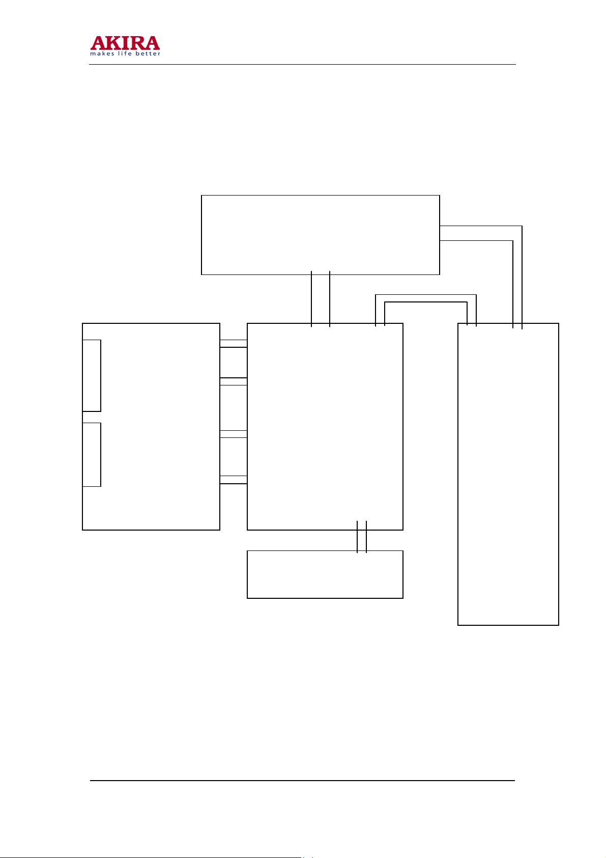
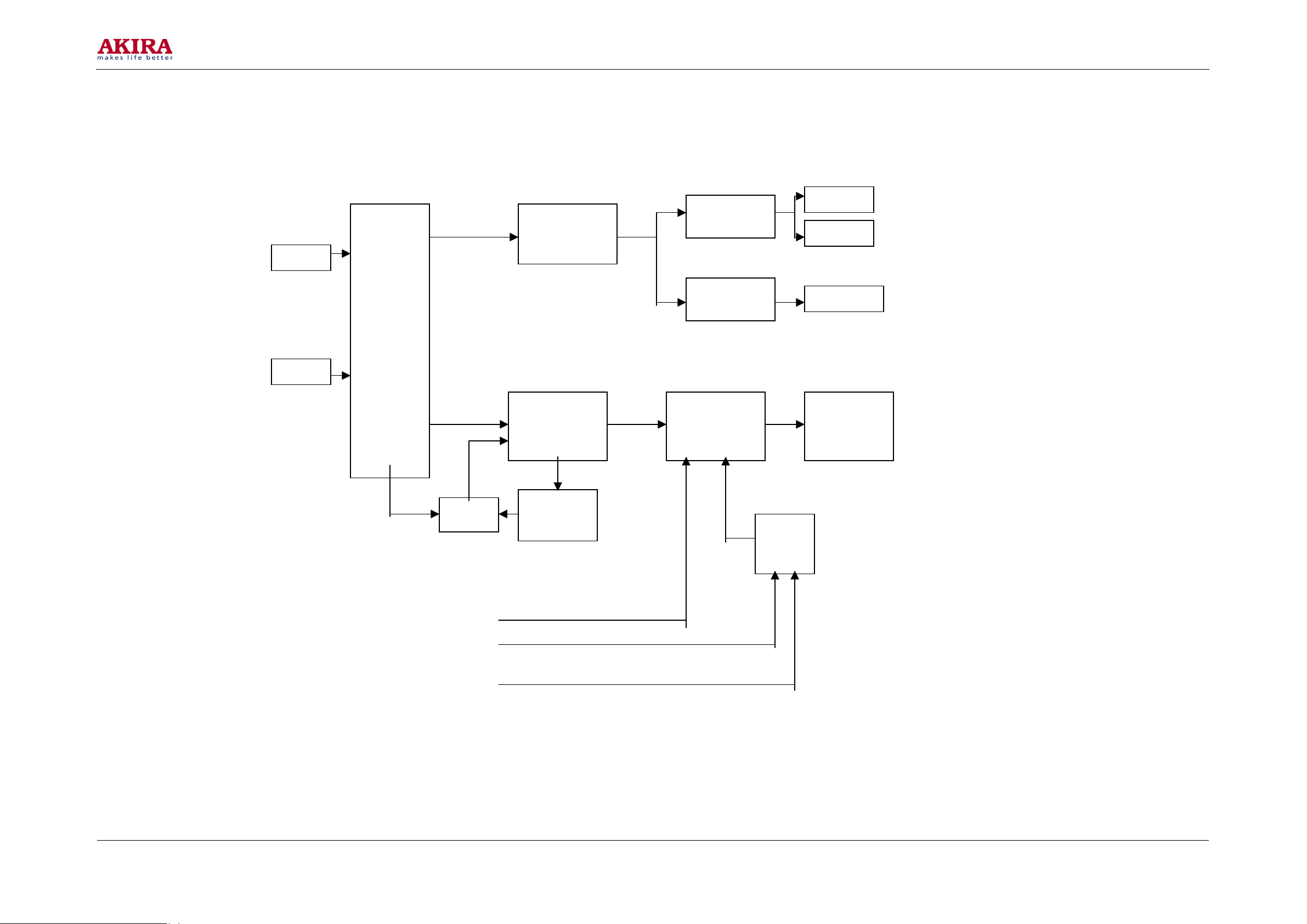
BLOCK DIAGRAM
XP4
XP7 XP3
TUNNER BOARD
XP2
XP8
PANEL
P40 CN801
CN904
CN902
MAIN BOARD
CN901
XP301
KEY BOARD
XP501 XP511
POWER BOARD
Model No.: LCT-32HSSTP
Version: 1.0
Page 6
-6 -
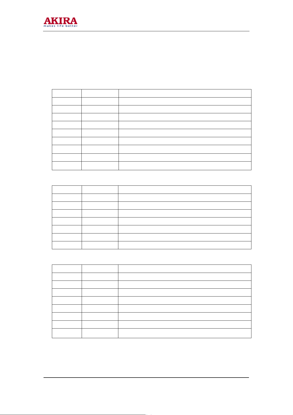
FUNCTION OF CONJUNCTION
CN801---XP501
ITEM NAME FUNCTION
1 5V FOR PANEL POWER
2 PS FOR POWER OFF
3 GND GND
4 14V FOR AUDIO POWER
5 PGND AUDIO GND
6 12V FOR MAIN POWER
7 12V FOR MAIN POWER
8 GND FOR MAIN GND
9 GND FOR MAIN GND
CN902---XP4
ITEM NAME FUNCTION
1 GND FOR AUDIO GND
2 14V FOR AUDIO POWER
3 14V FOR AUDIO POWER
4 GND FOR AUDIO GND
5 12V FOR AUDIO POWER
6 GND FOR AUDIO GND
7 5.0V TUNNER POWER
CN901---XP2
ITEM NAME FUNCTION
1 ADC1 FOR SCART1 AUTO IDENTIFY
2 ADC2 FOR SCART1 AUTO IDENTIFY
3 GND GND
4 MUTE AUDIO MUTE
5 RESET MSP3410 RESET
6 GND GND
7 SDA FOR SERIAL DATA
8 SCL FOR SERIAL CLOCK
Model No.: LCT-32HSSTP
Version: 1.0
Page 7
-7 -
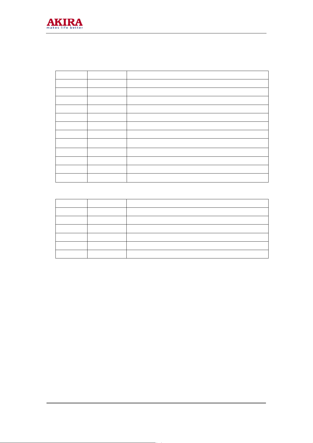
CN901---XP2
ITEM NAME FUNCTION
1 GND GND
2 CVBS FOR TV'S CVBS SIGNAL
3 GND GND
4 GREEN FOR SCART GREEN
5 GND GND
6 RED FOR SCART RED
7 GND GND
8 FB FOR FAST BLANK
9 GND GND
10 BLUE FOR SCART BLUE
11 GND GDN
12 AVOUT FOR MONITOR OUT
CN903---XP1
ITEM NAME FUNCTION
1 AV1-IN FOR VIDEO1 IN
2 GND GND
3 AV2-IN FOR VIDEO2 IN
4 GND GND
5 S-CIN FOR C-IN
6 GND GND
Model No.: LCT-32HSSTP
Version: 1.0
Page 8
-8 -
P40
ITEM NAME FUNCTION
1 PWM PWM Dimming
2 APWM Analog PWM dimming
3 ON/OFF Backlight On~Off: 2.4-5.0V On
0-1V Off
4 GND
5 RX0- LVDS signal
6 RX0+ LVDS signal
7 GND
8 RX1- LVDS signal
9 RX1+ LVDS signal
10 GND
11 RX2- LVDS signal
12 RX2+ LVDS signal
13 GND
14 RCLK- LVDS clock signal
15 RCLK+ LVDS clock signal
16 GND
17 RX3- LVDS signal
18 RX3+ LVDS signal
19 GND
20 N.C.
21 N.C.
22 N.C.
23 GND
24 GND
25 GND
26 Panel_power Module power
27 Panel_power Module power
28 Panel_power Module power
29 Panel_power Module power
30 Inverter_power Inverter logic power
Model No.: LCT-32HSSTP
Version: 1.0
Page 9
SIGNAL DIAGRAM
SCART1
SCART2
TUNER
A1
U401
U400
VPC3230
U703
SDA5550M
DV1
VGA
YPBP
N1
MSP3410
N4
TDA7266B
N5
LM358
U500
GM1501
-9 -
SPEAKER
SPEAKER
EARPHONE
PANEL
U702
PI5V330
Model No.: LCT-32HSSTP
Version: 1.0
Page 10

POWER DIAGRAM
-10 -
CN801
U802
LM1086
U801
U800
GND
1
GND
2
LM2576
+5V
LT1117-3.3
U810
LT1117-3.3
U803
LT1117-1.8
U500
GM1501
U600
K4D263238
U400
VPC3230
U903
AM29LV040
3
4
5
6
7
8
9
12V
PGND
14V
GND
SW
5V
U902
IRF7314
U805
LT1117-2.5
12V
U901
LM7809
14V
9V
Main board
N301
TDA7266B
N302
CD4052
Inverter_logic_power
U806
Panel_power
120V
1
120V
2
120V
3
N303
NJW1137
N304
LM358
LCD
GND
4
GND
5
GND
6
GND
7
Model No.: LCT-32HSSTP
Version: 1.0
Page 11

,6,7,
N7,8(3.3V
)
TROUBLESHOOTING
NO PICTURE
CN801
PIN6:12V
YES
FB703
PIN1:5V
YES
U806
PIN5
YES
U802
PIN2:3.3V
YES
U801(3.3V) U803(1.8V)
U805(2.5V) U810(3.3V)
YES
U402
PIN5,6(5V)
PI
YES
FB400(5V)FB401(3.3)
FB402(5V)FB403(5V)FB
YES
OK
8:5
-11 -
NO
NO
REPLACE
POWER BOARD
NO
NO
NO
REPLACE
U800
REPLACE
U802
NO
REPLACE
U402
NO
REPLACE
U806
REPLACE
U801ORU803ORU8
05OR810
REPLACE
U402
Model No.: LCT-32HSSTP
Version: 1.0
Page 12

-12 -
(
,
NO N
NO TELETEXT
YES
U809(2.5V)
YES
FB409(3.3V)FB410
(2.5V)FB411(3.3V)
FB412
3.3V)
YES
REPLACEU70
U704,U706
3
REPLACE
U809
O
REPLACE
FB409FB410FB411FB412
Model No.: LCT-32HSSTP
Version: 1.0
Page 13

-13 -
NO SOUND
YES
A1
PIN4
YES
N1 PIN27,
YES
N4 PIN1, PIN2,
PIN4, PIN5
NO
NO
NO
REPLACE
A1
REPLACE
N1
REPLACE
N4
NO
N4
PIN7(4.5)
CHECK
V3
V4
YES
OK
Model No.: LCT-32HSSTP
Version: 1.0
Page 14

-14 -
WALL-MOUNTING BRACKET INSTALLATION GUIDE
READ CAREFULLY BEFORE INSTALLATION!
THE INSTALLATION GUIDE SHOULD BE RETAINED FOR FUTURE REFERENCE.
Caution:
1. Do NOT attempt to install the TV by yourself to avoid mistakes or hazard. Refer all installation to
qualified servicing personnel.
2. DO NOT install the TV on a wall aslope or a wall that makes the TV screen sloping over 25 off
plumb line. Otherwise, it may cause tumble or injury.
3. One must follow the instructions in this guide to correctly install the TV.
4. It requires more than one person to install the TV.
5. Before installation, examine whether the wall conforms to the specifications and whether the
supplied parts can be fixed on it. The wall for mounting should sustain the weight of TV and
speakers, e.g. cement wall or brick wall. DO NOT attempt to install an area with standard building
rigidity, which sustains the weight of the TV and speakers. If the rigidity of the wall can not be
measured, every mounting hole should sustain a frontal force over 75N,and a shearing force of
over 150N.
6. Use the specified electric drill and drill bit for drilling. The drilling holes should conform to the
specifications.
7. To avoid fire and shock, do NOT place radiator, heater or humidifier below the installed TV.
8. The TV should be kept away from moisture, sensors and power line. The tv should be kept away
from impact and vibration.
9. Ensure that the power supply be disconnected before installation for fear of fire and shock.
Wall-mounting Installation Steps:
1. Take out the bracket form the package and check if there are serious defects (e.g. infirm juncture).
2. Adjust the bracket to the desired angle. Use bolt 7 to adjust the angle by meeting holes of column
beam2 and holes of lever 4.
3. Drill locating holes in the specified dimension in a vertical wall of concrete or brick. The hole size
should be 11mm. The hole depth should accommodate the expanding tube of the bolt.
4. Fix the bolts into the drilled holes in step3, and then cover each bolt with a metal washer. Meet the
four mounting holes in the bracket with the four bolts in the wall, cover each bolt with a metal
washer, then fasten with a screw nut. Check its rigidity by pulling the bracket.
5. Fix the fixture disk to the back cover of the TV using six M4x20 bolts.
6. Wall-mount the TV by putting the six-fixture disk into the six mounting holes A.
Model No.: LCT-32HSSTP
Version: 1.0
Page 15

Wall-mounting quick guide
-15 -
Model No.: LCT-32HSSTP
Version: 1.0
Page 16

-16 -
Model No.: LCT-32HSSTP
Version: 1.0
Page 17

CIRCUIT DIAGRAM
-17 -
Model No.: LCT-32HSSTP
Version: 1.0
Page 18

-18 -
Model No.: LCT-32HSSTP
Version: 1.0
Page 19

-19 -
Model No.: LCT-32HSSTP
Version: 1.0
Page 20

-20 -
Model No.: LCT-32HSSTP
Version: 1.0
Page 21

-21 -
Model No.: LCT-32HSSTP
Version: 1.0
Page 22

-22 -
Model No.: LCT-32HSSTP
Version: 1.0
Page 23

-23 -
Model No.: LCT-32HSSTP
Version: 1.0
Page 24

-24 -
Model No.: LCT-32HSSTP
Version: 1.0
Page 25

-25 -
Model No.: LCT-32HSSTP
Version: 1.0
Page 26

-26 -
PART L IS T
CODE DESRIPTION
103246
103247
101814
101808
1011691
1020374
1005288
1004899
1004693
1013110
1013122
1020322
101227
Digital board
Tuner board
Front control board
Switch board
LCD panel
Remote control
Inverter connector
Cable to panel
AC cord
Speaker
Speaker
Uesr's manual
Back cover
RSAG2.908.452
RSAG2.908.451
RSAG2.908.337
RSAG2.908.313
LTA320W1-L02
HYDFSR-A026AK
SP030623770R1
SP030910890
PHP-206+PHS-301
YD83E-10W8R-B
YDG50-10W8R-A
IES040937
WTG6.170.071
1020333
1020311
1020323
1019700
Front encloser
Rating label
Carton box
Signal cord
RSAG8.074.096\W9+B2\SYN135
E/RSR8.807.1377
E/RSR8.865.1511
SCART-S-2.0
Model No.: LCT-32HSSTP
Version: 1.0
Page 27

 Loading...