

Page 1

LCD TV
Service Manual
Page 2

- 2 -
MODEL:
LCT-32EL0SSTP
Model No.: LCT-32ELOSSTP.doc
Version: 1.0
Page 3
- 3 -
CONTENTS
SAFETY PRECAUTION.........................................................................................................................4
SPECIFICATION..................................................................................................................................... 6
DISPLAY OV ERV IEW.......................................................................................................................... 10
ADJUSTMENT STANDARD................................................................................................................12
FIRMWARE UPDATE........................................................................................................................... 15
FACTORY MENU.................................................................................................................................18
TROUBLESHOOTING......................................................................................................................... 19
BLOCK DIAGRAM ..............................................................................................................................22
BILL OF MATERIAL............................................................................................................................ 24
CIRCUIT DIAGRAM............................................................................................................................37
EXPLODED VIEW AND PART LIST ..................................................................................................46
WALL-MOUNTING BRACKET INSTALLATION GUIDE................................................................ 47
Model No.: LCT-32ELOSSTP .doc
Version: 1.0
Page 4
- 4 -
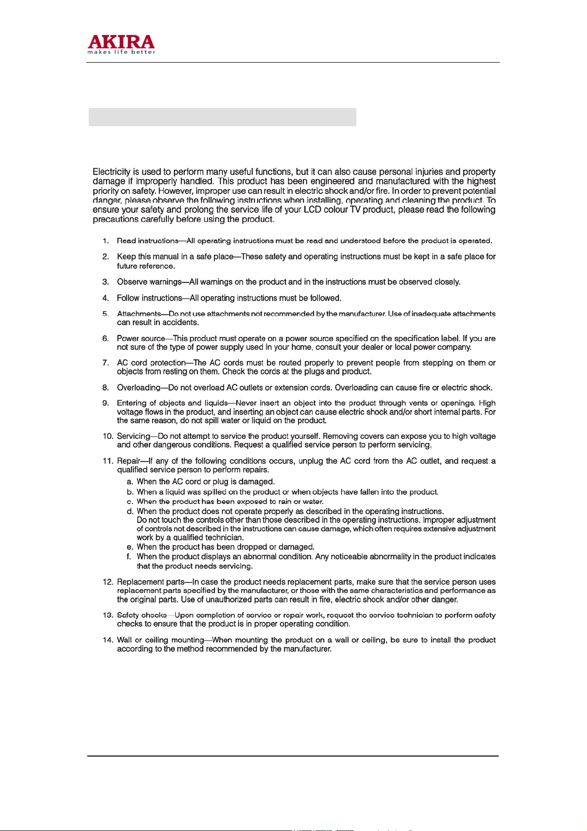
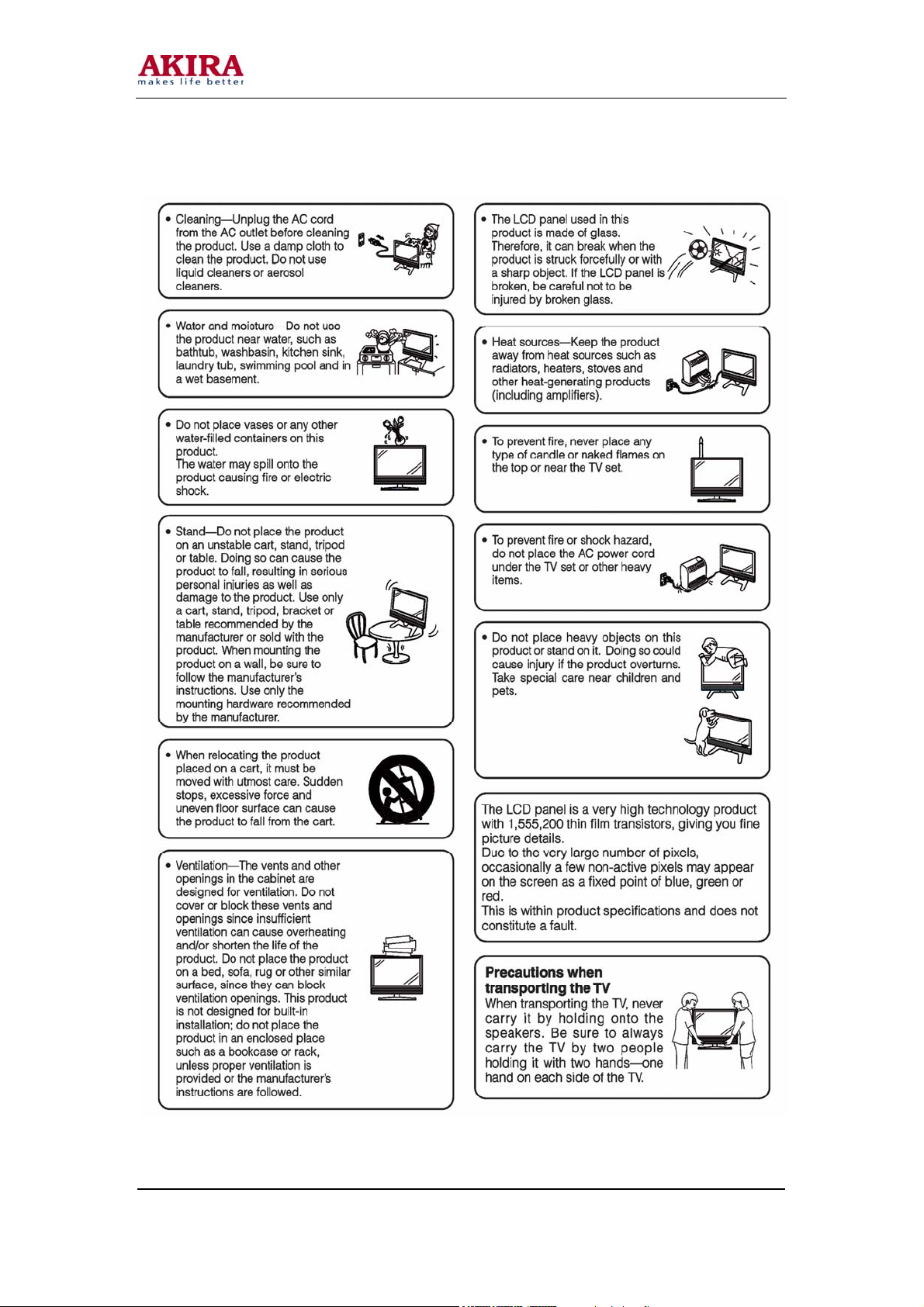
IMPORTANT SAFETY PRECAUTION
Model No.: LCT-32ELOSSTP .doc
Version: 1.0
Page 5
- 5 -
Model No.: LCT-32ELOSSTP.doc
Version: 1.0
Page 6

6
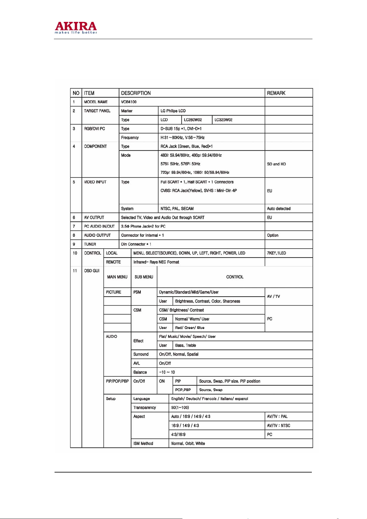
SPECIFICATION
Panel Type 32” Wide TFT Colour LCD
Display Area 697.685mm * 392.256mm
Display Color (8bit) 16.7 million
Pixel Pitch 170.25um * 510.75um * RGB
Panel
Recommended Resolution 1366 * 768
Contrast Ratio 500(Min), 600(Typ)
Luminance white 500 cd/㎡
Viewing Angle
PC
Viewing angle free (R/L 176(Typ.), U/D
176 (Typ.)
Analog RGB 15 pin D-Sub Input
DVI Input
Composite Input
S-Video Input
In/Out
RF Signal
Others
Video
Audio Composite Input
Euro A/V SCART1(Full), SCART2(Half)
Antenna 75Ω Coaxial cable
Color System PAL/SECAM
Sound System B/G,D/K,I,L
Stereo Type NICAM, A2
Text TELETEXT
Power Consumption 160 Watts
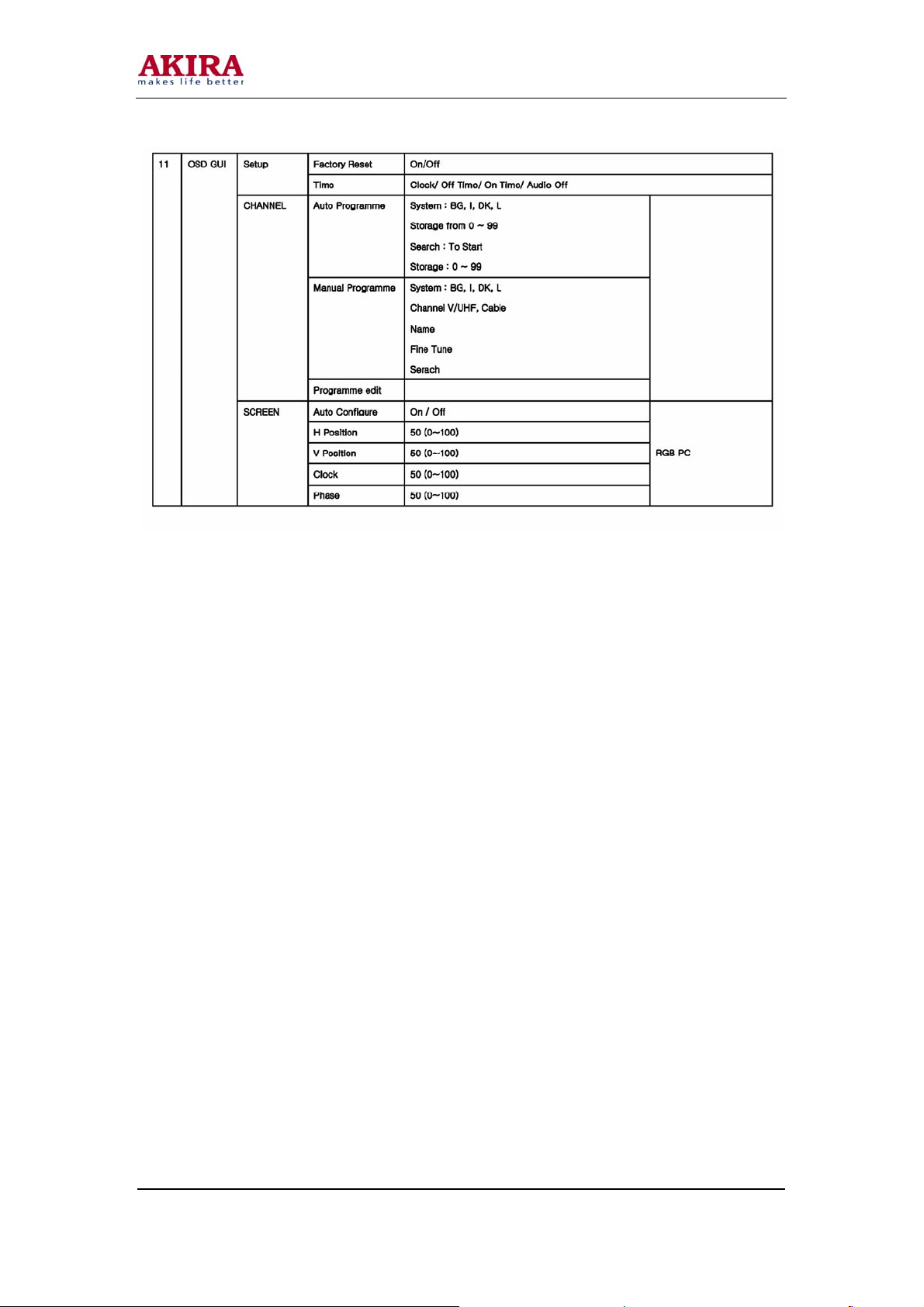
SCART1, 2 Input
Component1, Input
PC(analog RGB) Input
DVI Input
Component 1, Input
Headphone Output
SCART1,2 Input
PC/DVI Audio Input
Power Save Mode Less then 5 watts
Speaker 10 Watts *2
Plug & Play DDC 1/2 B
Screen Control
Weight
Model No.: LCT-32ELOSSTP.doc
Version: 1.0
16 Colour On Screen Display Meun, Bit
Map
Net: 20.1kg
Page 7
7
Gross:24.6kg
Remote Controller Yes
Dimension
Specification are subject to changes without prior notice.
Model No.: LCT-32ELOSSTP .doc
Version: 1.0
932(W)*238(D)*567(H) : Speaker(stand
included)
Page 8
8
Chassis General Spec
Model No.: LCT-32ELOSSTP .doc
Version: 1.0
Page 9
9
Model No.: LCT-32ELOSSTP .doc
Version: 1.0
Page 10
10
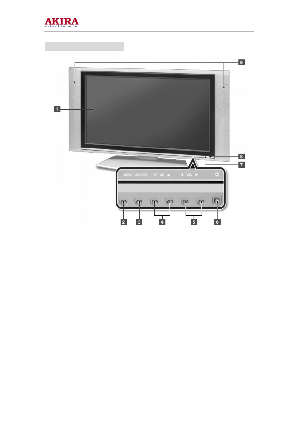
DISPLAY OVERVIEW – Front View
1) LCD Display : Displays the current contents of the display.
2) MENU Button : Displays the main OSD menu. Exitx from a sub-menu.
3) SOURCE Button : Displays a menu of all of the available input sources.
4) Channel(▼/▲) Buttons : Press CH(▲) or CH(▼) to change channels. Also used to
select the OSD menu.
5) Volume(◄ / ►)Buttons : Press VOL(◄) or VOL(►) to change the volume. Also use to
increase or reduce values in an OSD menu.
6) POWER Buttons : Press this button is Standby mode to turn off the LCD TV.
(Use this button after pressing the main power button on the rear panel of the LCD TV.)
7) Remote Control Receiver :The function for receiving the radio waves emitted from
the remote control.
8) Power Indication Lamp : If the AC cord is connected, the red lamp is on,
9) External Speakers : Output device for LCD TV sound
Model No.: LCT-32ELOSSTP.doc
Version: 1.0
Page 11
11
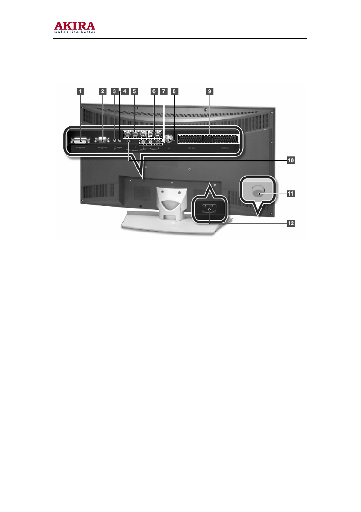
Rear View
1) DVI-D : Connects the DVI cable to the Dvi connector on the computer.
2) ANALOG RGB : Connects the VGA signal cable to the VGA connector on the
computer.
3) PC AUDIO INPUT : Connect to the audio-output port of a PC.
4) Head Phone Jack : Connects with a headphone.
5) COMPONENT VIDEO INPUT : Jack for connecting the DVD player (or VCR player or
Digital TV playback player)
6) COMPONENT AUDIO INPUT : Jack for connection the DVD player (or DTV) audio
input connector.
7) AV : Composite : -Composite Video IN : Connect with the Video input terminal
from a VCR(or DVD Player)
. -Audio L/R IN : Connect with the Audio-Left/Right from a
VCR(or DVD Player)
8) ANT (VHF/UHF) Connector : Connect with an external cable from the external
antenna.
9) SCART1 (Full) / SCART2(Half) (PAL Model) : Connects PAL-method TV Audio/Video.
10) S-VIDEO : S-Video signal from an S-VHS VCR or Laserdisc player.
11) Main Power Button : Press this button to switch the LCD TV main power on/off. (To
use the TV,
12) AC Input Connector : To input AC power cable from a power outlet.
Model No.: LCT-32ELOSSTP .doc
Version: 1.0
Page 12

12
ADJUSTMENT STANDARD
APPLICATION
This standard is applied on all LCD TV models with VCB3001 and VCB3002 Chassis.
ASSIGNMENT
This chassis is a non-charging type with insulated power unit. Therefore, insulated
transformer is not required. In order to protect the adjustment unit, however, it is
recommended that an insulated transformer between the power supply line and input side of
chassis is to be operated and adjusted.
The adjustment should follow the order strictly. However, it may be revised considering the
productivity.
Without any other specification, the adjustment should be performed in the surrounding
temperature of 25±5°C and humidity of 65±10%.
When adjustment, the input voltage of receiver should be maintained at 220V, 60Hz.
Without any other specification, the receiver should be operated for about 15 minutes before
the adjustment.
- The pre-operation should be performed after receiving 100% White Pattern of Pattern
General
- Not Used Patten generator White Pattern Entering method
a) Enter into setup mode pressing menu key on the adjustment R/C.
b) Selecting White after entering ISM Mode using arrow keys in setup menu of R/C,
then 100% Full White Pattern will be shown.
The setup can be heartrun without any specific signal generator in this mode.
(Caution) When the screen is kept still more than 20 minutes, “After-image” around black level may
happen (especially for Digital pattern or Cross Hatch pattern which have clear white/black colors).
ADJUSTMENT ITEM
1) EDID(The Extended Display Identification Data )/DDC(Display Data Channel)
download
2) AD9883A-Set Adjustment
3) White Balance Adjustment
4) Main/Sub Color Adjustment
1. EDID(The Extended Display IdentificationData) / DDC(Display Data Channel) download
a)The information is exchanged without user’s command to PC or monitor since they are
specified in VESA. In other words, the function is made for “Plug and Play” which
reconfigures user’s environment to be used in no time while automatically communicating
with monitor.
Model No.: LCT-32ELOSSTP .doc
Version: 1.0
Page 13
13
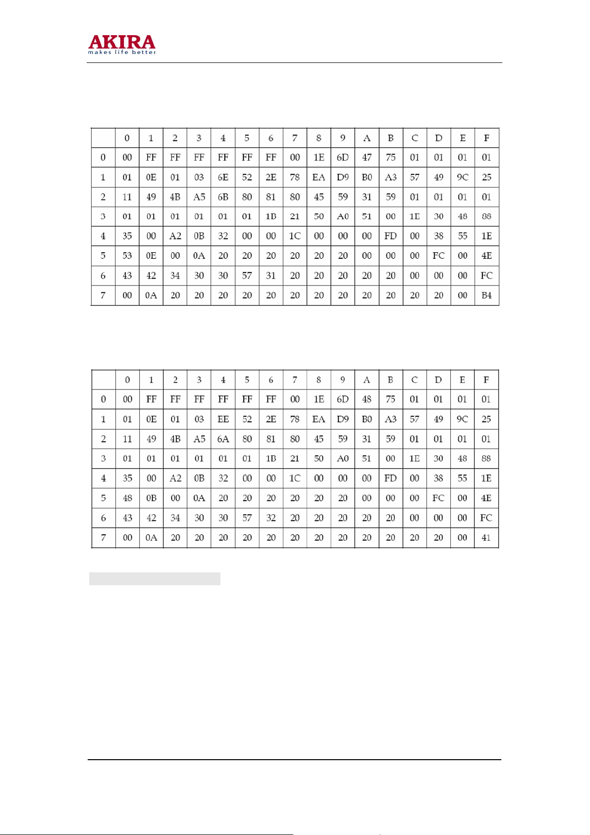
b) Analog EDID DATA (RGB)
c) Digital EDID DATA (DVI)
2. AD9883A-Set Adjustment
a) Introduction Analog Adjustment for AD9883A-Set => This is a function for the optimal level of
black and gain to be automatically set from digital converter and RGB variation to be adjusted.
b) Used Equipment
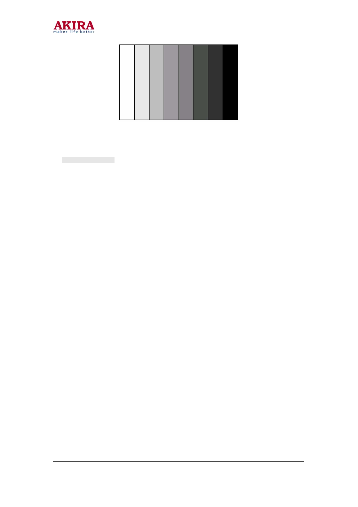
Pattern Generator(capable of generating 720P Vertical 100% Color Bar
Pattern (The pattern type is shown as follows and the caution should be used not to
confused with 75% color bar which is a close pattern) and the level of output should be
precisely adjusted within 0.7± 0.1Vp-p
Model No.: LCT-32ELOSSTP .doc
Version: 1.0
Page 14
14
<Figure> Adjustment Pattern : 720P Vertical Color Bar>
3. Adjustment Method
Input 100% Vertical Color Bar Pattern (TVBAR_100)
in 720P Mode which may be supported for
Component input, and then select Component1 or
Component2 for input and “STANDARD” for image.
Wait for more than a second after receiving signal
and press S.SELECT on adjustment R/C (Service
remote controller) while selecting “WB Adjust” for
automatic adjustment.
In case of abnormal adjustment, perform the re-adjustment after confirming Patter or adjustment
condition.
When adjustment is done, exit the adjustment mode pressing S.SELECT.
Model No.: LCT-32ELOSSTP.doc
Version: 1.0
Page 15
15
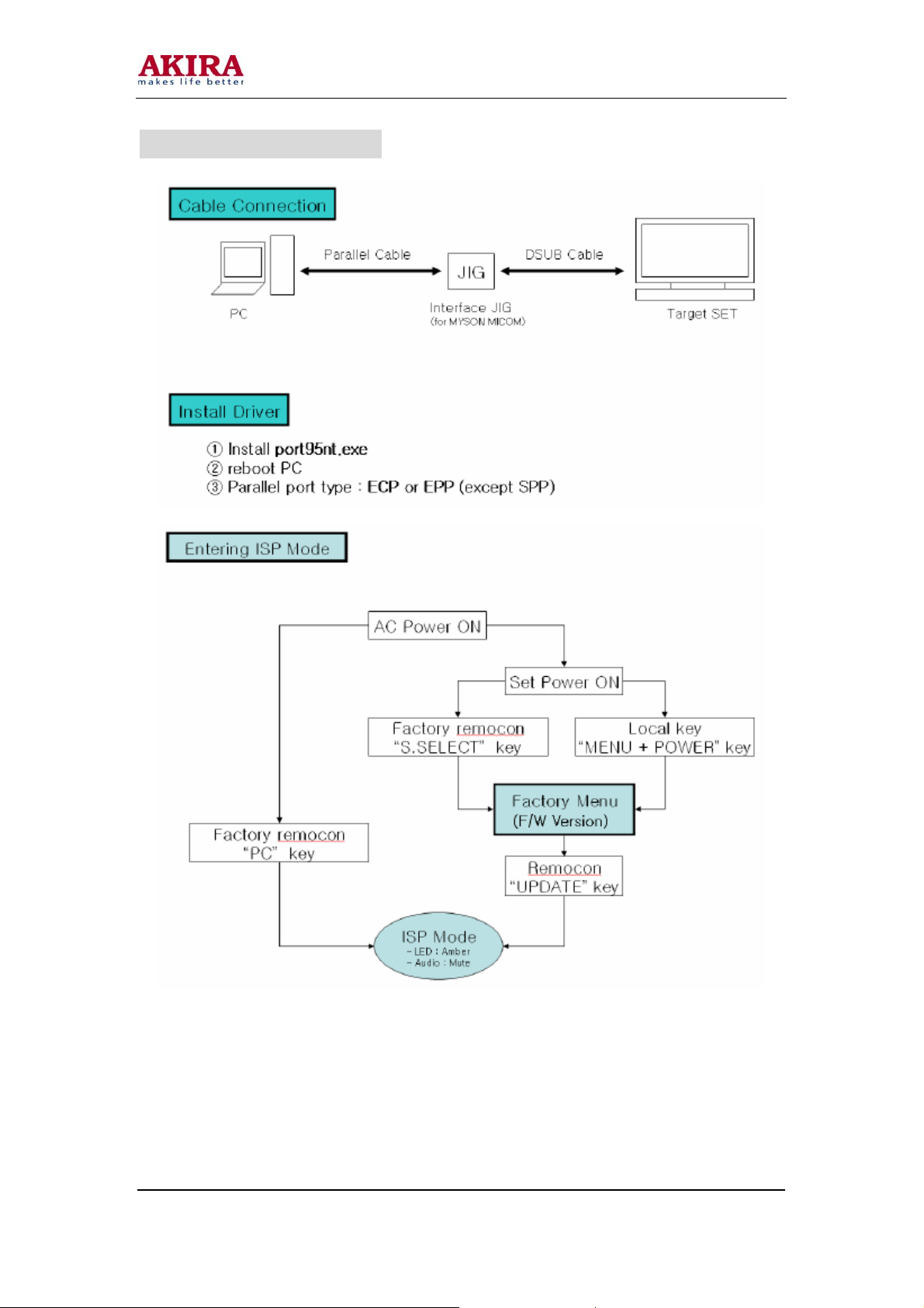
FIRMWARE UPDATE
Model No.: LCT-32ELOSSTP.doc
Version: 1.0
Page 16

16
Model No.: LCT-32ELOSSTP.doc
Version: 1.0
Page 17

17
Model No.: LCT-32ELOSSTP.doc
Version: 1.0
Page 18

18
FACTORY MENU
Model No.: LCT-32ELOSSTP.doc
Version: 1.0
Page 19

19
TROUBLESHOOTING
Power Related
Model No.: LCT-32ELOSSTP.doc
Version: 1.0
Page 20

20
Screen Related
Model No.: LCT-32ELOSSTP.doc
Version: 1.0
Page 21

21
Sound Related
Model No.: LCT-32ELOSSTP.doc
Version: 1.0
Page 22

22
BLOCK DIAGRAM – Main Board
Model No.: LCT-32ELOSSTP.doc
Version: 1.0
Page 23

23
Power Board
Model No.: LCT-32ELOSSTP.doc
Version: 1.0
Page 24

24
B.O.M
Item Desc. Item Spec.
PWB(PCB) ASSY,MAIN VCB4100 MAIN TOTAL
PWB(PCB) ASSY,MAIN VCB4100 MAIN HAND INSERTING
BOARD LABEL VCB4100
JACK AUDIO PHONE JACK 3.5PIE NINENEW SJ3501-5 H7 2 J12 J19
AV-JACK J/B 9P + DIN (RCA/Mini-Din 1 J11
D-SUB 15F- BLUE DSH03A-15F-BU 15P D-SUB 2.29MM FEMALE RIGHT ANGLE 1 J8
CONNECTOR(CA-29DVI-A-2) 29P DVI-I CIRCUIT RIGHT ANGLE ( 1 J9
SCART JACK RC103 SCART JACK 21P 2 J13 J14
WAFER SMW200-05 5P YEON-HO 2.0mm STRAIGHT
WAFER SMW200-04 4P YEON-HO 2.0mm STRAIGHT 1 J23
WAFER SMW200-02 2P YEON-HO 2.0mm STRAIGHT 2 J16 J17
WAFER SMW200-07 7P YEON-HO 2.0mm STRAIGHT
WAFER SMW200-10 10P YEON-HO 2.0mm STRAIGHT 1 J1
WAFER SMW200-14 14P YEON-HO 2.0mm STRAIGHT 1
TUNER TECH0849PG31A(S) -NTSC SAMSUNG 1 U36
TUNER CABLE Phone(A) TO PAL(A) L=150MM TUNER (MAIN )TO TV 1 U36
SAW FILTER,EPCOS X6966M-M100 IF filter for digital cable TV (PAL ) 1 U41
AXIAL,INDUCTOR AL02TB-R33K 3.3UH//44MA 5.0MM 1 L58
Al. CAPCITOR/SAMYOUNG 470UF 16V M 8*11.5*5.0 -SHL-TYPE 5
Al. CAPCITOR/SAMYOUNG 220UF 16V M 6.3*11*2.5 -SHL TYPE 7 C46 C399 C416 C472 C474 C490 C513
Al. CAPCITOR/SAMYOUNG 100UF 16V M 5*11*2.5 SHL-TYPE
Al. CAPCITOR/SAMYOUNG 47UF 50V M 5*11*2 SHL-TYPE 4 C400 C452 C453 C464
Al. CAPCITOR/SAMYOUNG 100UF 50V M 8*11*3.5 SHL-TYPE 1 C440
QTY
1 2 3 4
J6
C22 C24 C143 C149 C422
C31 C362 C373 C389
20
C476 C493 C495 C496 C499 C500 C503 C511 C512 C977
Location Number
5 6 7 8 9 10
C415 C421 C434 C435 C436 C445
Model No.: LCT-32ELOSSTP.doc
Version: 1.0
Page 25

25
Al. CAPCITOR/SAMYOUNG 22UF 50V M 5*11*2.5 SHL-TYPE 1 C359
Al. CAPCITOR/SAMYOUNG 4.7UF 50V M 5*11*2.5 SHL-TYPE 1 C405
Al. CAPCITOR/SAMYOUNG 3.3UF 50V M 5*11*2.5 SHL-TYPE 1 C367
Al. CAPCITOR/SAMYOUNG 10UF 16V M 5*11*2.5 SHL-TYPE 5 C44 C161 C162 C167
IC,EON FLASH ROM EN29LV004A-70 PLCC32P 1 U42
MICOM LABEL VCB4200 1 U2
IC, MYSON MYSON MTV412MV FLASH128K PLCC44 1 U2
PWB(PCB) ASSY,MAIN VCB4100 MAIN SMT TOP
CAPACITOR, CHIP CERAMIC 10NF 50V K X7R 1608 R/TP 12
CAPACITOR, CHIP CERAMIC 1NF 50V K X7R 1608 R/TP 12
CAPACITOR, CHIP CERAMIC 100PF 50V J NPO 1608 R/TP 7 C14 C15 C51 C52
CAPACITOR, CHIP CERAMIC 0.33UF 10V K X7R 1608 R/TP 4 C382 C384 C385 C387
CAPACITOR, CHIP CERAMIC 0.47UF 10V K X7R 1608 R/TP 19
CAPACITOR, CHIP CERAMIC 1UF 10V K X7R 1608 R/TP 16
CAPACITOR, CHIP CERAMIC 0.1UF 16V K X7R 1608 R/TP 110
4.7NF 50V X7R 1608 R/TP 4 C448 C450 C468 C470
C28 C96 C97 C424 C441 C442 C443 C444 C447 C449
C467 C469
C29 C47 C66 C84
C169 C170
C377 C378 C379 C380
C397 C406 C407 C412
C1 C3 C4 C5 C456 C457 C458 C459 C460 C461
C463 C471 C473 C489 C978 C979
C2 C8 C11 C16
C32 C34 C45 C48
C61 C62 C63 C69
C76 C77 C78 C79
C99 C100 C101 C102 C103 C104 C105 C106 C107 C108
C109 C110 C111 C112
C293 C294 C295 C363 C364 C365 C366 C368 C369 C372
C374 C375 C376 C390 C391 C394 C398
C402 C403 C404 C408 C409 C410 C411 C413 C417 C418
C168
C153 C154 C157 C158 C163 C164
C54 C56 C57
C381 C383 C386 C388 C395 C396
C475 C507 C508 C509 C510
C17 C18 C19
C49 C50 C55 C58 C59 C60
C70 C71 C72 C73 C74 C75
C89 C90 C91 C92 C93 C98
C113 C114 C115 C116 C117 C140
C30
C401
Model No.: LCT-32ELOSSTP .doc
Version: 1.0
Page 26

26
CAPACITOR, CHIP CERAMIC 15PF 50V J NP0 1608 R/TP 1 C6
CAPACITOR, CHIP CERAMIC 12PF 50V J NP0 1608 R/TP 5 C414 C419 C477 C478 C479
CAPACITOR, CHIP CERAMIC 470PF 50V J NP0 1608 R/TP 6 C125 C128 C130 C134
CAPACITOR, CHIP CERAMIC 220PF 50V J NP0 1608 R/TP 4 C145 C147 C151 C462
CAPACITOR, CHIP CERAMIC 47PF 50V J NP0 1608 R/TP 3 C121 C127 C132
CAPACITOR, CHIP CERAMIC 27PF 50V J NP0 1608 R/TP 2 C505 C506
CAPACITOR, CHIP CERAMIC 33PF 50V J NP0 1608 R/TP 4 C9 C10 C94 C95
CAPACITOR, CHIP CERAMIC 330PF 50V J NP0 1608 R/TP 11
CAPACITOR, CHIP CERAMIC 68PF 50V J NP0 1608 R/TP 2 C12 C13
CAPACITOR, CHIP CERAMIC 27NF 50V K X7R 1608 R/TP 1 C425
CHIP RESISTOR 0 1/8W J 2012 D.R/TP 5 R575 R576 R577 R578
CHIP RESISTOR 0 1/10W J 1608 D.R/TP 43
CHIP RESISTOR 1K 1/10W J 1608 D.R/TP 26
CHIP RESISTOR 1.2K 1/10W J 1608 D.R/TP 1 R625
CHIP RESISTOR 100K 1/10W J 1608 D.R/TP 1 R448
CHIP RESISTOR 1.3K 1/10W J 1608 D.R/TP 1 R652
47NF 50V K X7R 1608 R/TP 18
C426 C432 C433 C439 C446 C451 C454 C455 C465 C466
C481 C482 C483 C487 C488 C491 C492 C494 C497 C498
C501 C502 C504 C514
C138 C480
C122 C123 C135 C136
C371
C141 C142 C146 C148 C152 C370
C64 C65 C67 C68
C87 C88 C428 C430 C431 C484 C485 C486
C80 C81 C82 C83 C85 C86
L18
R9 R10 R82 R97
R126 R142 R144 R158
R187 R188 R189 R190
R511 R513 R515 R534 R535 R541 R554 R563 R602 R641
R642 R1014 R1015 R604
R5 R13 R33 R39
R261 R446 R447 R464 R468 R469 R477 R481 R483 R485
R593 R598 R601 R613 R614 R621
R101 R103 R105 R114 R115 R116
R161 R163 R165 R167 R171 R186
R197 R202 R207 R211 R497 R502
R83 R244 R245 R250 R251 R256
Model No.: LCT-32ELOSSTP.doc
Version: 1.0
Page 27

27
CHIP RESISTOR 1.8K 1/10W J 1608 D.R/TP 1 R555
R11 R12 R87 R91
CHIP RESISTOR 10K 1/10W J 1608 D.R/TP 26
CHIP RESISTOR 100 1/10W J 1608 D.R/TP 77
R145 R170 R173 R179
R592 R594 R597 R617
R40 R41 R42 R43 R44 R45 R47 R56 R57 R58
R59 R62 R64 R66 R69 R71 R73 R74 R76 R78
R176 R257 R258 R262 R263 R449 R450 R451 R452 R453
R455 R456 R457 R458 R459 R461 R465 R466 R467 R471
R95 R96 R108 R119 R120 R122
R216 R221 R237 R239 R243 R591
R619 R651
R14 R16 R22 R24 R32 R34 R36 R38
R473 R474 R475 R484 R486 R487 R494 R499 R504 R505
R506 R507 R508 R509 R517 R518 R524 R525 R527 R528
R600 R616 R618 R623 R624 R632 R633 R634 R635
CHIP RESISTOR 1M 1/10W J 1608 D.R/TP 2 R37 R493
CHIP RESISTOR 2.2K 1/10W J 1608 D.R/TP 2 R6 R470
CHIP RESISTOR 120K 1/10W J 1608 D.R/TP 2 R580 R582
CHIP RESISTOR 12K 1/10W J 1608 D.R/TP 1 R585
CHIP RESISTOR 27 1/10W J 1608 D.R/TP 1 R657
R117
CHIP RESISTOR 22 1/10W J 1608 D.R/TP 15
CHIP RESISTOR 33K 1/10W J 1608 D.R/TP 1 R588
CHIP RESISTOR 220K 1/10W J 1608 D.R/TP 8 R248 R249 R254 R255 R259 R260 R264 R265
CHIP RESISTOR 200 1/10W J 1608 D.R/TP 1 R228
CHIP RESISTOR 1 R 1/10W J 1608 D.R/TP 3 R543 R648 R649
CHIP RESISTOR 24K 1/10W J 1608 D.R/TP 3 R584 R586 R587
CHIP RESISTOR 27K 1/10W J 1608 D.R/TP
CHIP RESISTOR 30K 1/10W J 1608 D.R/TP 2 R236 R242
CHIP RESISTOR 20K 1/10W J 1608 D.R/TP 1 R79
CHIP RESISTOR 270 1/10W J 1608 D.R/TP 2 R159 R169
R137
R123
R138
R129
R444
R130
R445
R131
R132 R133 R134 R135 R136
R501
Model No.: LCT-32ELOSSTP.doc
Version: 1.0
Page 28

28
CHIP RESISTOR 3.3K 1/10W J 1608 D.R/TP 1 R599
CHIP RESISTOR 22K 1/10W J 1608 D.R/TP 1 R92
CHIP RESISTOR 47K 1/10W J 1608 D.R/TP 2 R551 R552
R27
CHIP RESISTOR 470 1/10W J 1608 D.R/TP 25
CHIP RESISTOR 56 1/10W J 1608 D.R/TP 3 R98 R102 R104
CHIP RESISTOR 180 1/10W J 1608 D.R/TP 1 R542
CHIP RESISTOR 4.7K 1/10W J 1608 D.R/TP 51
CHIP RESISTOR 47 1/10W J 1608 D.R/TP 3 R109 R118 R658
CHIP RESISTOR 33 1/10W J 1608 D.R/TP 12
CHIP RESISTOR 330 1/10W J 1608 D.R/TP 1 R462
CHIP RESISTOR 6.8K 1/10W J 1608 D.R/TP 1 R500
CHIP RESISTOR 82 1/10W J 1608 D.R/TP 4 R224 R225 R234 R235
CHIP RESISTOR 150 1/10W J 1608 D.R/TP 2 R93 R656
CHIP RESISTOR 390 1/10W J 1608 D.R/TP 1 R156
CHIP RESISTOR 510 1/10W J 1608 D.R/TP 1 R653
CHIP RESISTOR 470K 1/10W J 1608 D.R/TP 4 R203 R208 R212 R603
CHIP RESISTOR 820 1/10W J 1608 D.R/TP 1 R141
CHIP RESISTOR 75 1/10W J 1608 D.R/TP 27
CHIP ARRAY RESISTOR 47 M3216, ROHM, CHIP ARRAY RESISTOR
R480 R490 R491 R492 R605 R606 R607 R626 R627 R628
R636 R638 R654 R655 R659
R1 R2 R4 R7 R8 R17 R18 R19 R20
R26 R28 R29 R31 R35 R49 R50 R51 R52 R53
R54
R75
R229 R521 R522 R573 R620 R643 R644 R645 R646 R1002
R1003
R99
R182
R110 R111 R112 R157 R160 R162 R166 R168 R172 R194
R199 R204 R213 R217 R219 R220 R222 R226 R230 R231
R232 R233 R238 R240 R241 R608 R609
16
RA11 RA12 RA13
R246 R247 R252 R253 R454 R472 R476 R478 R479
R55
R60
R61 R81 R63
R77
R80
R100
R124 R125 R164 R174 R175 R178 R180 R181
R183
RA4
RA14
R23
R65
R84
R67 R89 R68
R88
R121
R70
R143
R72
R227
RA5
RA15
RA6
RA16
RA7
RA17
RA8
RA18
RA9
RA19
RA10
Model No.: LCT-32ELOSSTP.doc
Version: 1.0
Page 29

29
CHIP BEAD HB-1H1608-300 CERATEC 1608MM R/TP 9
CHIP BEAD HH-1M2012-121 CERATEC 2012MM R/TP 29
CHIP INDUCTOR FI-B2012-332-KJT 3.3UHCERATEC 2012MM R/TP 6 L27 L34 L36 L37 L38 L39
CHIP INDUCTOR FI-B2012-103-KJT 10UH CERATEC2012MM R/TP 2 L54 L55
CHIP INDUCTOR FI-B2012-561-KJT 0.56UH CERATEC2012MM R/TP 1
IC,INTERGRAL REGULATOR 1.0A 1.8V IL-1117-18 2 U47 U49
IC,INTERGRAL REGULATOR 1.0A 2.5V IL-1117-25 1 U8
IC,INTERGRAL REGULATOR 1.0A 5.0V IL-1117-50 2 U51 U52
IC,INTERGRAL REGULATOR 1.0A 3.3V IL-1117-33 4 U45 U46 U48 U50
TRANSISTOR SAMSUNG TR KSC1623, KEC KTC3875 13
IC,ROHM BA17809FP 1A/9V Low drop-out voltage type TO252-3 1 U35
IC,ROHM BA17808FP 1A/8V Low drop-out voltage type TO252-3 1 U10
IC,MICRONAS
DIODE KEC SOT-23 KDS184 2 D1 D5
IC,CATALIST 24WC02 8P SOIC TP EEPROM 1
IC,CATALIST 24WC16 8P SOIC TP EEPROM 3 U3 U38 U13
IC,SAMSUNG
IC, SONY
IC, MSTAR MST6151 1 U31
IC,MITSUBISHI M51958-BFP SOP8P
IC, FAIRCHILD FDC6326L TP FAIRCHILD 16V 2.4A E 1 U12
IC,PHILIPS
VIDEO-CONTROLLER-TEXT-IF-AUDIO IC FAMILY
VCTI49X-D2YIF MQFP144
K4D263238F-QC50 1M*32BIT *4BANK DDR SDRAM 250M 2.5V
LQFP100
CXA2069Q S2-Compatible 7-Input 3-Output Audio/Video
Switch QFP-64P
BSS83 MOSFET N-channel enhancement switching transistor
sot143b-4p
L26 L28 L29 L30 L31 L32 L33 L35 L68
L3 L4 L9 L10 L14 L17
L22 L23 L24 L25 L48 L49 L53 L57 L60 L72
L74 L76 FB1
L50
L51 L52 R574 R579 R589 R690
L59
Q1
Q19
Q3
Q20
Q7
Q8 U53 Q9 Q10
Q21
1 U34
U15
1 U16
1 U32
1 U1
2 U5 U6
L19 L20 L21
Q16 Q17 Q18
Model No.: LCT-32ELOSSTP .doc
Version: 1.0
Page 30

30
CRISTAL SX-1 SMS, 14.318MHZ CL 18PF 1 Y1
CRISTAL SX-1 SMS, 20.250MHZ CL 18PF 1 X2
CRISTAL SX-1 SMS, 12.000MHZ CL 20PF 1 X1
IC
IC, TEXAS INSTRUMENT 10W STEREO AUDIO POWER AMPLIFIER TPA3004 QFP48P 1 U43
IC, TEXAS INSTRUMENT TPA6110A2 SOP-8P 150mW STEREO AUDIO POWER AMPLIFIER 1 U44
IC, PHILIPS 74LVC/LVT14ADR2 14P,SOIC TP LEVE 1 U14
IC, PHILIPS 74HC4066D SOP 14P 1 U4
DIODE ZENER UDZ S 5.6B TP ROHM-K SOD323 200MW 5.6V 5MA 13
DIODE,SWITCHING BAV99 TP ON-SEMI SOT-23 80V 300M 18
SOCKET SOCKET PLCC 32P MAOYEE INDUSTRY 1 U42
SOCKET SOCKET PLCC 44P MAOYEE INDUSTRY 1 U2
WAFER 12507WR-30 YEON-HO 30P 1.25MM Right Angle 1 J21
PCB VCB4100 VPM-0059AA(FR-4 2LAYER 1.6T)
K6R4008V1D 512Kx8 Bit High Speed Static RAM(3.3V
Operating).
1 U39
ZD2
ZD12
D2
D13
The data are subject to change without prior notice.
ZD3
ZD13
D3
D14
ZD4
ZD14
D4
D15
ZD5 ZD6 ZD7 ZD8 ZD9 ZD10 ZD11
D6 D16 D7
D17
D8
D19
D9 D20 D10
D21
D11 D12
Model No.: LCT-32ELOSSTP.doc
Version: 1.0
Page 31

31
CIRCUIT DIAGRAM
Model No.: LCT-32ELOSSTP.doc
Version: 1.0
Page 32

32
Model No.: LCT-32ELOSSTP .doc
Version: 1.0
Page 33

33
Model No.: LCT-32ELOSSTP.doc
Version: 1.0
Page 34

34
Model No.: LCT-32ELOSSTP.doc
Version: 1.0
Page 35

35
Model No.: LCT-32ELOSSTP.doc
Version: 1.0
Page 36

36
Model No.: LCT-32ELOSSTP.doc
Version: 1.0
Page 37

37
Model No.: LCT-32ELOSSTP .doc
Version: 1.0
Page 38

38
Model No.: LCT-32ELOSSTP.doc
Version: 1.0
Page 39

PCB – Top Silk
39
Model No.: LCT-32ELOSSTP .doc
Version: 1.0
Page 40

PCB- Bottom Silk
40
Model No.: LCT-32ELOSSTP .doc
Version: 1.0
Page 41

41
PCB - Bottom Solder
Model No.: LCT-32ELOSSTP.doc
Version: 1.0
Page 42

42
Model No.: LCT-32ELOSSTP .doc
Version: 1.0
Page 43

43
Model No.: LCT-32ELOSSTP.doc
Version: 1.0
Page 44

44
Model No.: LCT-32ELOSSTP .doc
Version: 1.0
Page 45

45
Model No.: LCT-32ELOSSTP.doc
Version: 1.0
Page 46

46
EXPLODED VIEW
Model No.: LCT-32ELOSSTP.doc
Version: 1.0
Page 47

47
WALL-MOUNTING BRACKET INSTALLATION GUIDE
READ CAREFULLY BEFORE INSTALLATION!
THE INSTALLATION GUIDE SHOULD BE RETAINED FOR FUTURE REFERENCE.
Caution:
1. Do NOT attempt to install the TV by yourself to avoid mistakes or hazard. Refer all
installation to qualified servicing personnel.
2. DO NOT install the TV on a wall aslope or a wall that makes the TV screen sloping over
25º off plumb line. Otherwise, it may cause tumble or injury.
3. One must follow the instructions in this guide to correctly install the TV.
4. It requires more than one person to install the TV.
5. Before installation, examine whether the wall conforms to the specifications and whether
the supplied parts can be fixed on it. The wall for mounting should sustain the weight of TV
and speakers e.g. cement wall or brick wall. DO NOT attempt to install an area with
standard building rigidity, which sustains the weight of the TV and speakers. If the rigidity
of the wall can not be measured, every mounting hole should sustain a frontal force over
75N, and a shearing force of over 150N.
6. Use the specified electric drill and drill bit for drilling. The drilling holes should conform to
the specifications.
7. To avoid fire and shock, do NOT place radiator, heater or humidifier below the installed TV.
8. The TV should be kept away from moisture, sensors and power line. The TV should be
kept away from impact and vibration.
9. Ensure that the power supply be disconnected before installation for fear of fire and shock.
Wall-mounting Installation Steps:
1. Take out the bracket form the package and check if there are serious defects (e.g. infirm
juncture).
2. Adjust the bracket to the desired angle. Use bolt 7 to adjust the angle by meeting holes of
column beam2 and holes of lever 4.
3. Drill locating holes in the specified dimension in a vertical wall of concrete or brick. The
hole size should be 11mm. The hole depth should accommodate the expanding tube of the
bolt.
4. Fix the bolts into the drilled holes in step3, and then cover each bolt with a metal washer.
Meet the four mounting holes in the bracket with the four bolts in the wall, cover each bolt
with a metal washer, and then fasten with a screw nut. Check its rigidity by pulling the
bracket.
5. Fix the fixture disk to the back cover of the TV using six M4x20 bolts.
6. Wall-mount the TV by putting the six-fixture disk into the six mounting holes A.
Model No.: LCT-32ELOSSTP.doc
Version: 1.0
Page 48

 Loading...