

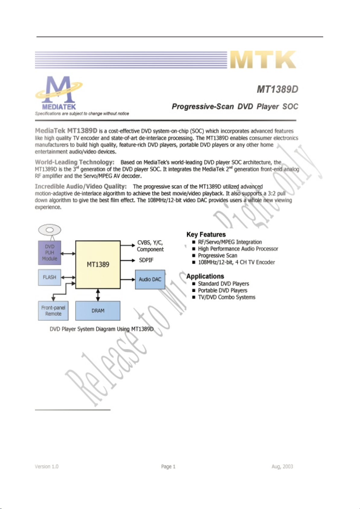
Page 1

DVD PLAYER
Model:
DVP4797KDMC
SERVICE MANUAL
www.akai.ru
Page 2

Daewoo DA Service Manual
Table of Contents
Page
General Section..........................................................................................2-5
Caution/Warnings
Safe Warnings
Precautions
Software Upgrade
Circuit Diagram and Component Layout.......................................................6-26
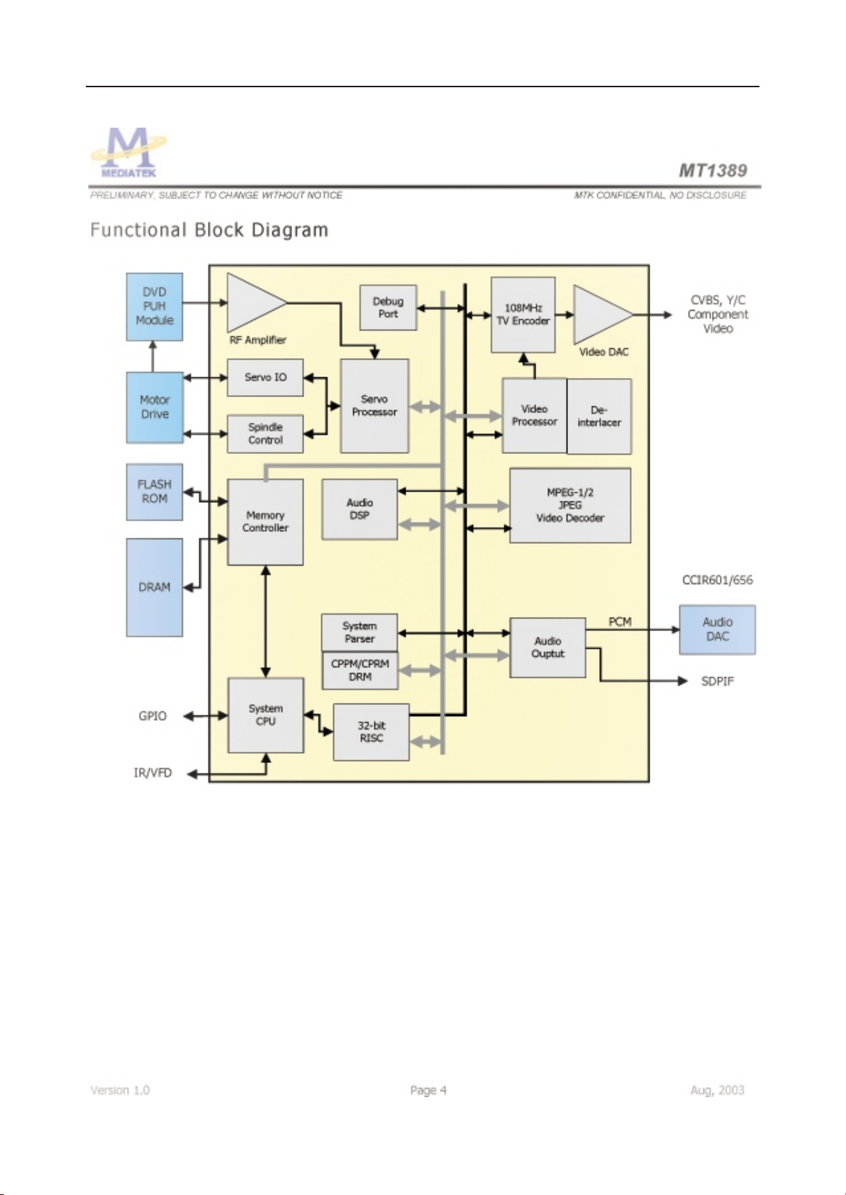
MPEG IC Block Diagrams
Power supply Circuit Diagram and Component Layout
MPEG Circuit Diagram and Component Layout
Front panel Circuit Diagram and Component Layout
Servicing Procedures..............................................................................27-33
Power Supply Trouble Service Flow Chart
Read Disc Trouble Service Flow Chart
Video Trouble Service Flow Chart
Composite Analogy Audio Trouble Service Flow Chart
Digital Audio Trouble Service Flow Chart
Front Control Trouble Service Flow Chart
Remote Control Trouble Service Flow Chart
Parts List.............................................................................. ..................34-37
Power Part List
MPEG Part List
Front Panel Part List
Karaoke Panel Part List
Page 1
Page 3
1. General Section
1.1 Cautions/Warnings
1.1.1 Product Safety Notice
Parts marked with the symbol in the schematic diagram have critical char-
acteristics.
Use ONLY replacement pares recommended by the manufacturer.
It is recommended that the unit be operated from a suitable DC supply or batter-
ies during initial check out procedures.
CAUTION
RISK OF ELECTRIC SHOCK
DO NOT OPEN
WARNING HIGH VOLTAGE INSIDE TO PREVENT
ELECTRICAL SHOCK DO NOT REMOVE ANY CO-
VER OR SCREW. REFER ALL SERVICING TO QU-
ALIFIED SERVICE PERSONNEL. DO NOT ALLOW
THIS PRODUCTION BE EXPOSED TO RAIN OR
MOISTURE. DISCONNECT THIS MAINS PLUG
FROM THE SUPPLY SOCKET WHEN NOT IN
USE.
1.1.2 Leakage Current Check/Resistance Check
Before returning the unit to the customer, make sure you make either (1) a
leakage current check or (2) a line to insulated resistance check.
If the leakage current exceeds 0.5 milliamps , or if the resistance from chas-
sis to either side of the power cord is less than 240 K ohms, the unit is defec-
tive.
WARNING: DO NOT return the unit to the customer until the problem or loca-
ted and corrected.
1.2. Safe Warnings
1.2.1. Protection of Eyes from Laser Beam
To protect eyes from invisible laser beam during servicing
DO NOT LOOK AT THE LASER BEAM
Page 2
Page 4

1.2.2 Laser Caution
CAUTION
Adjusting the knobs, switches, and controls , ect. Or taking actions not
specified herein may result in a harmful emission of laser beams.
This CD Changer must be adjusted and repaired only by qualified serv ice
personnel.
CAUTION- INVISIBLE LASER RADIATION WHEN OPEN AND INTERLOCKS
DEFEATED AVOID EXPOSURE TO BEAM.
VORSICHTI- UNSICHTBARE LASERSTRAHLUNG TRITT AUS. WENN DECKEL
GEOFFNET UND WENN SICHERHEITSVERRIEGELUNG
uBERBRuCKT IST. NICHT DEM STRAHL AUSSETZENI
VARNING- OSYNLIG LASERSTRALNING NAR DENNA DEL AR OPPNAD OCH
SPARR AR URKOPPLAD STRALEN AR FARLIG.
ADVARSEL-USYNLIG LASERSTRALING VED ABNING NAR
SIKKERHEADSAFBRYDERE ER UDE AF FUNKTION. UNDGA
UDSAETTELSE FOR STRALING.
CLASS 1 LASER PRODUCT
LUOKAN 1 LASERLAITE
KLASS 1 LASERAPPARAT
THIS IS COMPACT DISC PLAYER IS CLASSIFIED AS A CLASS LASER
PRODUCT.
THE LASS 1 LASER PRODUCT LABEL IS LOCATED ON THE REAR EX TERIOR.
1.3. Precautions
1.3.1. ESD Precautions in Repairing
1.3.1.1 Do not apply excessive pressure on the mechanical parts (movi ng pares), including the Pickup Block, as extremely high mechanical pre cision or required in these parts.
1.3.1.2 When soldering the microprocessor and signal processing IC s,
use a ceramic soldering iron or a soldering iron whose metal part is grou nded since they are not resistant to static electricity.
1.3.1.3 When removing the solder or soldering the laser shorting lands
for the Pickup Block, use a ceramic soldering iron or a soldering iron wh ose metal part is grounded since the laser diode or not resistant to static
electricity.
Page 3
Page 5

1.3.2. DVD Loading Unit Precautions When handing the
Mechanism Block
1.3.2.1 Do not loosen any screws in the Pickup Block.
1.3.2.2 Do not adjust any screws in the Mechanism Block except for
Tilt Adjust Screws , as they are adjusted precisely at the factory.
1.3.2.3 Replacement of the Pickup Block is impossible. Always repl ace the Traverse Ass s when the Pickup Block needed to be replace .
Do not touch the lens or lens holder of the Pickup Block.
1.3.2.4 The Guide Rails of the Pickup Block are greased. Take care wh en handing.
1.3.2.5 When you try to slide the Pickup Block, do not press or pull it
directly, Always turn the dive gears with your fingers.
1.3.2.6 Be sure that the anti-slipping rubber on the turnable or clean.
If there is dust or it is greasy,clean the part with the liquid that contains
50% each of alcohol and water.
1.3.2.7 When removing the Mechanism P.C.B. Ass s, you need to sho rt-circuit the laser diode shorting lands beforehand.
1.4. Software Upgrade
You can upgrade DVD player using the software we provide as following step:
The CD-R update is below lists:
First, burn CDR for upgrade. Dummy files are needed minimum 20Mbytes.
The burning software is Nero burning soft:
1. Volume name: WESTLAKE
2. Files name and type: ZORAN.BIN ( This file must locate Root directory)
3. CD-R burn type(formate): ISO9660
Model 1
ISO1 (level 1)
don t choice Jolient
don t choice loosen ISO strict
Notice: WESTLAKE and DWDVDP.BIN are upper case.
The CD upgrade process:
After the servo read the CD-R data ,Show Message on TV :
UPGRADE FILE DETECTED
UPGRADE ?
PRS CHOOSE (1-8Bit 2-16Bit)
Page 4
Page 6
Press 1 key , Show Message on TV
UPGRADE FILE DETECTED
UPGRADE ?
File Copy
The tray is automatic to open, take disc away.
UPGRADE FILE DETECTED
UPGRADE ?
Upgrading
At this time, please wait a few minutes, DVD is downloading code to flash, After
Logo will be show on TV again, the update process finish.
Notice: During upgrading , don s turn off power.
Displaying the software Version Number
After opening the tray, press the following keys on the remote control ,
DISPLAY (Up) (Down) (Left) (Right)
then the software version number appears.
Page 5
Page 7
Page 6
Page 8
Page 9
Page 10
Page 7
Page 11
Page 8
Page 12
Page 9
Page 13
Page 10
Page 14
Page 11
Page 15
Page 12
Page 16
Page 13
Page 17

Page 14
Page 18

Page 19

Page 16
Page 20

Page 17
Page 21

Page 18
Page 22

Page 19
Page 23

Page 20
Page 24

Page 21
Page 25

Page 22
Page 26

Page 23
Page 27

Page 24
Page 28

Page 25
Page 29

Page 26
Page 30

Page 27
Page 31

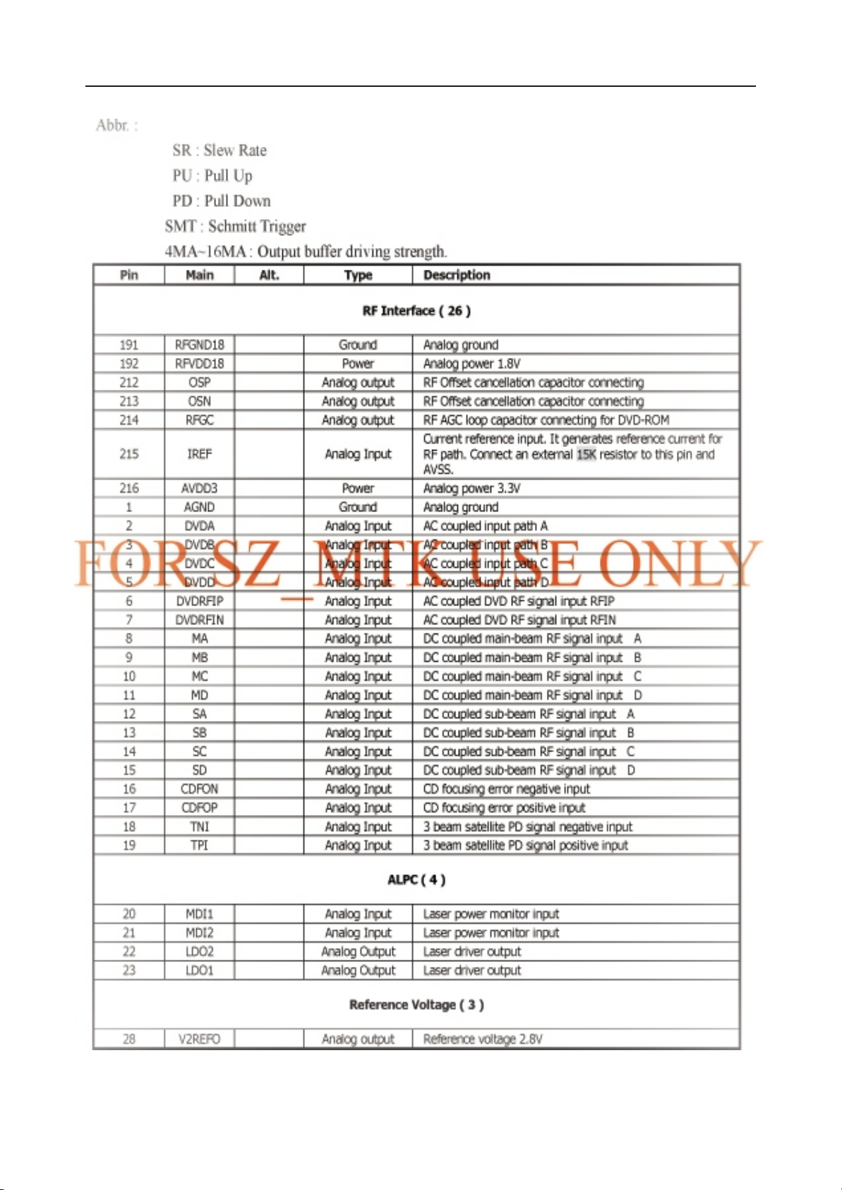
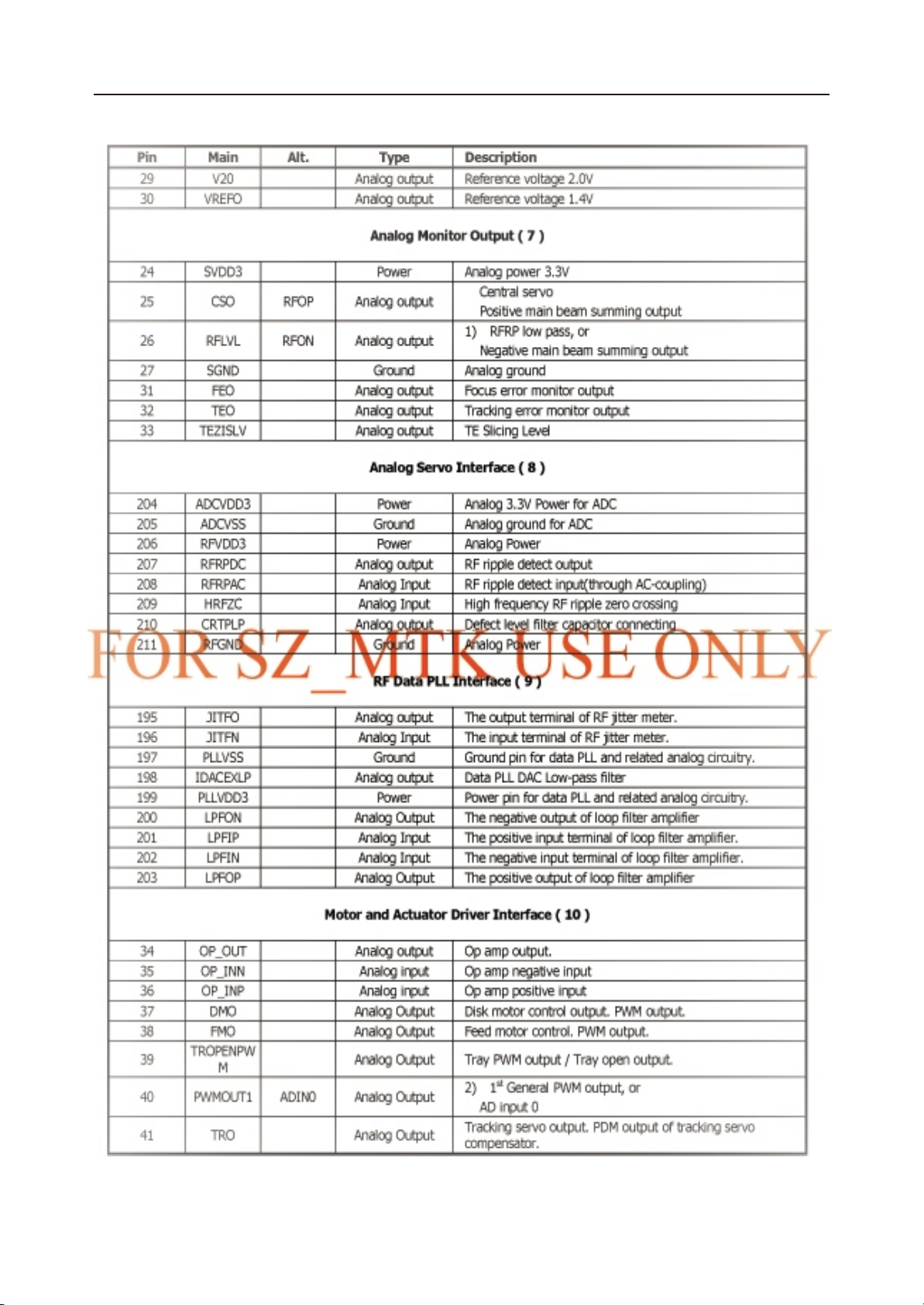
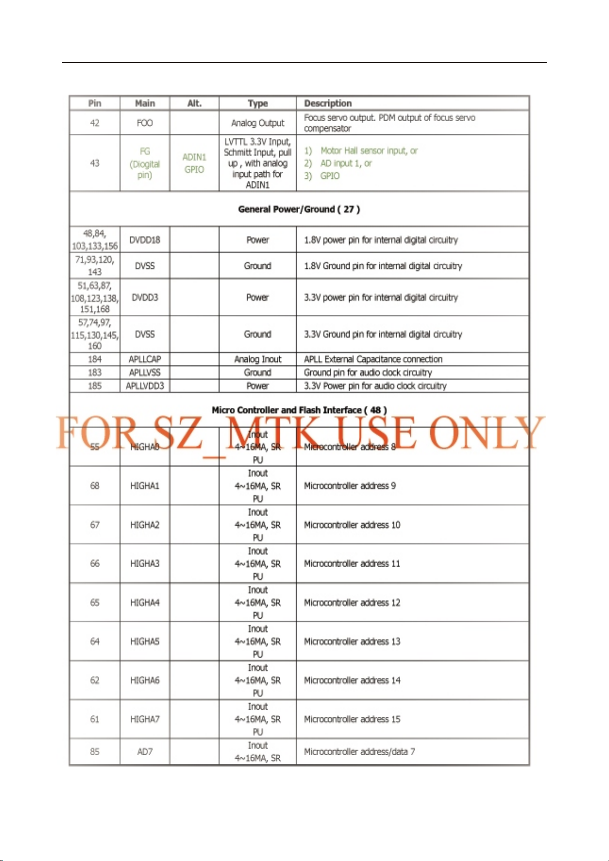
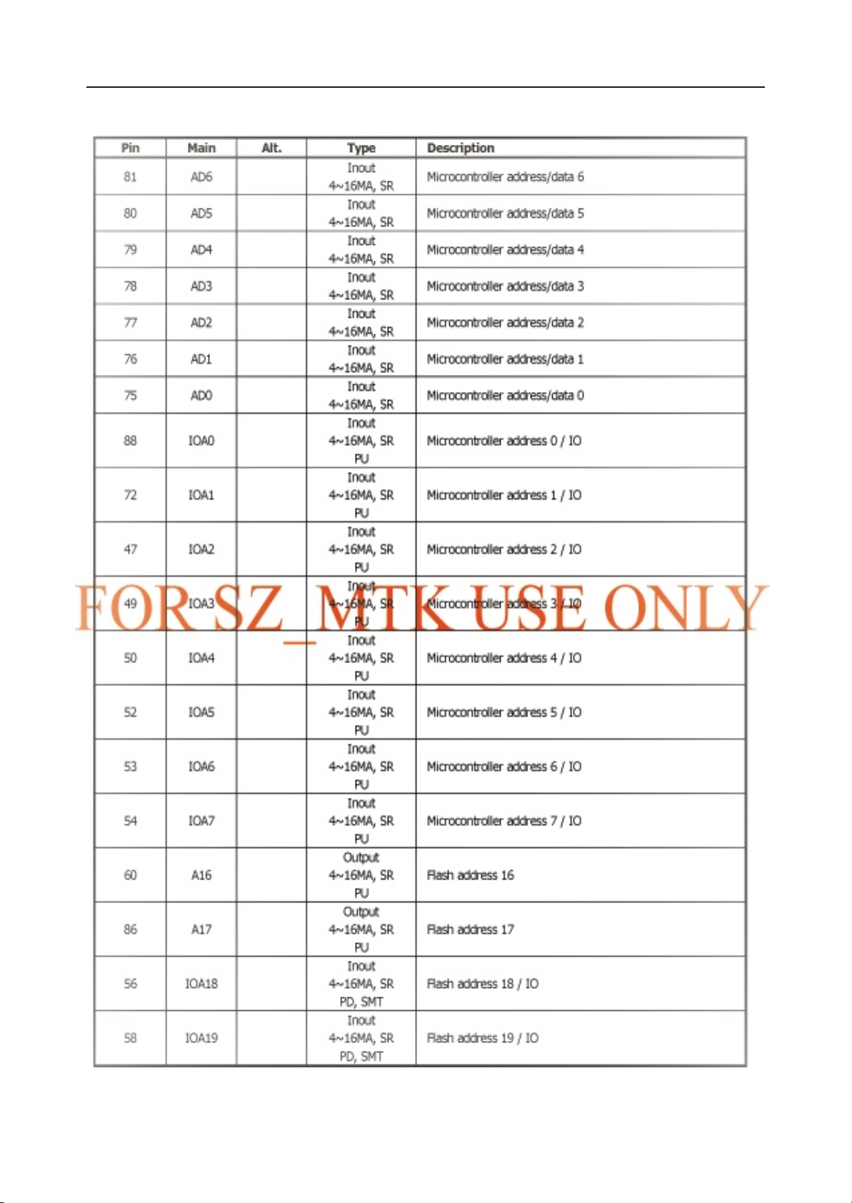
2.2 Power Supply Circuit Diagram and Component Layout
Fig2-2 Power Supply Circuit Diagram
5
D
V
0
5
2
L
A
2
0
3
T6
1
E
S
U
F
F2
Page 28Page 15
Page 32

Fig2-3 Power Supply Assembly Drawing
Page 29
Page 33

Fig2-4 Power Supply Bottom Routing
Page 30
Page 34

Fig2-3 Power Supply Assembly Drawing
Page 31
Page 35

Page 32
Page 36

Page 37

Page 38

Page 39

Part Name
PCS
Part name
CR02
LED Di sp la y PCS
PCS
Connector PCS
Materials List
Front Panel PCB Assy Modul
DVD4797 Front board
Page 40

Part No ED- DAE02 -02
PCS
R Carbon Film
Materials List
Modul
Page 41

Part No ED-DAE02-03
PCS
PCS
PCS
PCS
PCS
PCS
PCS
PCS
PCS
Materials List
Power PCB Assy Modul
Page 42

Part Name
CR02
CR02
CR02
CR02
CR02
CR02
CR02
CR02
CR02
CR02
CR02
CR02
CR02
CR02
CR02
CR02
CR02
CR02
CR02
CR02
CR02
CR02
CR02
CR02
CR02
CR02
CR02
CR02
CR02
CR02
CR02
CR02
Materials List
Front Panel PCB Assy Modul
Page 43

3.1. Power Supply Trouble Service Flow Chart
Power Supply
Block Trouble
NG
Check FusE1 Condition
Replace FusE1
OK
Check on D1/D2/D3/D4
Output Voltage Condition
NG
Check on U1 Pin2
Voltage Condition 13-18V
NG
Check on D6/EC2
parts
NG
Replace U1 Replace T1
NG
OK
Check CON1
Output Voltage
OK
Page 44

3.2. Read Disc Trouble Service Flow Chart
Read disc problem in a DVD player is a very complicated issue that may involve
complex issues. This problem is not only relation to the electronic circuit, but
also very much relation to the operation environment.
DVD loading unit is a very complicate part that contains big number of ESD com-
ponents , which require specific equipment, tools and technique to repair; In ge-
neral, service technician is not suggested to disassemble the DVD loading unit.
It is suggest proving the trouble and replacing the complete DVD loading unit, in-
stead of repairing the DVD loading unit in local workshop.
It is suggested to prove the faulty of a DVD loading unit by replacement by a good
DVD loading unit.
Before checking the NO DISC Trouble, ensure excluding the following possi-
bilities:
The test disc is damage.
AC power supply voltage dropped below the minimum required level.
DVD disc region code and color system is not matching to the DVD player or
system setting.
Moisture condensed inside the unit. (Power on the unit, without disc loaded,
for 1 / 2 to 2 hours).
Service Flow Chart
Read DISC Trouble
Check DVD LOADER
NG
Replace Connector
Connector Condition
OK
Replace DVD Loading Unit
NG
Check the MPEG ATAPI
I/F Interface Circuit
Check the other Parts by
Replacement Method
Page 45

3.3. Video Trouble Service Flow Chart
3.3.1. Composite Video Trouble Service Flow Chart
Composite Video Trouble
Check SETUP Item
OK
Check L3 Output Signal
OK
Check D8 Signal
OK
Check C166 Signal
OK
Check Cp1 Pin Signal
NG
NG
NG
NG
OK
See User Manual
Replace L3 Parts
Replace D8
Replace C166
Check External Set
NG
Replace Cp1
Page 46

5*12mm
5*12mm
5*12mm
5*12mm
6*12mm
6*12mm
7
8*12mm
Page 47

3.5. Digital Audio Trouble Service Flow Chart
Digital Audio Trouble
Check SETUP Item
OK
Check U8 Pin170 Signal
OK
Check C155/R98 Signal
OK
Check R401 Signal
OK
NG
NG
NG
NG
See User Manual
Replace U8
Replace
Replace
Check External set
OK NG
Check Con3
Replace Con3
Page 48

3.6. Front Control Trouble Service Flow Chart
Front Control Trouble
OK
Check SW7,SW8,SW9,SW10,SW11,SW12
NG
Replace
Page 49

3.7. Remote Control Trouble Service Flow Chart
Remote Control Trouble
Check Remote Control
OK
Check IR1 Pin3 Voltage
OK
Check IR1 Pin1 Output
Signal
OK
Check between 1CN1 and
Cn10 connection
NG NG
Replace Battery
NG
NG
NG
Check Power Supply
Replace IR1
Replace
Replace Control
OK
Replace U2
Page 50

Page 51

 Loading...