


ADC-M35

d
OPERATING INSTRUCTIONS
MANUAL DE INSTRUCCIONES
MODE D’EMPLOI
c
ADC-WRF35
ADC-RF35
ADC-M35
COMPACT DISC CHANGER
CAMBIADOR DE DISCOS COMPACTOS
ENGLISH
ESPAÑOL
FRANÇAIS
OWNER’S RECORD
For your convenience, record the model number
and serial number (you will find them on the rear of
your set) in the space provided below. Please refer
to them when you contact your AIWA dealer in
case of difficulty.
Model No. ADC-WRF35, ADC-RF35, ADC-M35
Serial No.

TABLE OF CONTENTS
FEATURES ..........................................................................................................................................2
PRECAUTIONS ................................................................................................................................... 3
UNPACKING ........................................................................................................................................ 4
INSTALLATIONS ................................................................................................................................. 5
CONNECTIONS .................................................................................................................................. 9
HOW TO USE ....................................................................................................................................12
SPECIFICATIONS ............................................................................................................................. 15
FEATURES
• Tracks from 6 CDs stored in the disc magazine
can be selected and played.
• Horizontal, vertical, slanted or suspended
installation can be made.
• This system allows you to connect the compact
disc changer to your car stereo that can receive
FM broadcasts.
Configuration of each system
ADC-WRF35
Compact disc changer, power unit & FM
modulator, wired remote control and wireless
remote control
ADC-RF35
Compact disc changer, power unit & FM
modulator and wired remote control
ADC-M35
Compact disc changer
NOTE
FOR USE IN THE U.S.A.
This equipment has been tested and found to
comply with the limits for a Class B digital device,
pursuant to Part 15 of the FCC Rules. These
limits are designed to provide reasonable
protection against harmful interference in a
residential installation.
This equipment generates, uses, and can radiate
radio frequency energy and, if not installed and
used in accordance with the instructions, may
cause harmful interference to radio
communications. However, there is no guarantee
that interference will not occur in a particular
installation. If this equipment does cause harmful
interference to radio or television reception, which
can be determined by turning the equipment off
and on, the user is encouraged to try to correct
the interference by one or more of the following
measures:
—Reorient or relocate the receiving antenna.
— Increase the separation between the
equipment and receiver.
—Connect the equipment into an outlet on
circuit different from that to which the receiver
is connected.
—Consult the dealer or an experienced radio/
TV technician for help.
EN
CAUTION
Modifications or adjustments to this product, which
are not expressly approved by the manufacturer,
may void the user’s right or authority to operate
this product.
2
PRECAUTIONS
•Do NOT install the unit in a location where it
may be subjected to:
—Direct sunlight or other sources of excessive
heat
—Fluid, rain or moisture
— Excessive dirt or dust
— Excessive vibration
• This unit is designed to be operated on a 12-volt
DC negative-ground electrical system only.
•Choose the mounting location carefully so that
the unit will not interfere with normal driving
functions.
• Berore making connections, disconnect the (
terminal of the car battery to avoid short
circuiting.
• Be sure to connect the red power input lead to
the positive 12-V power terminal, to which power
is supplied when the ignition key is in the
accessory position.
• The power unit & FM modulator is designed
only for this ADC-M35 compact disc changer.
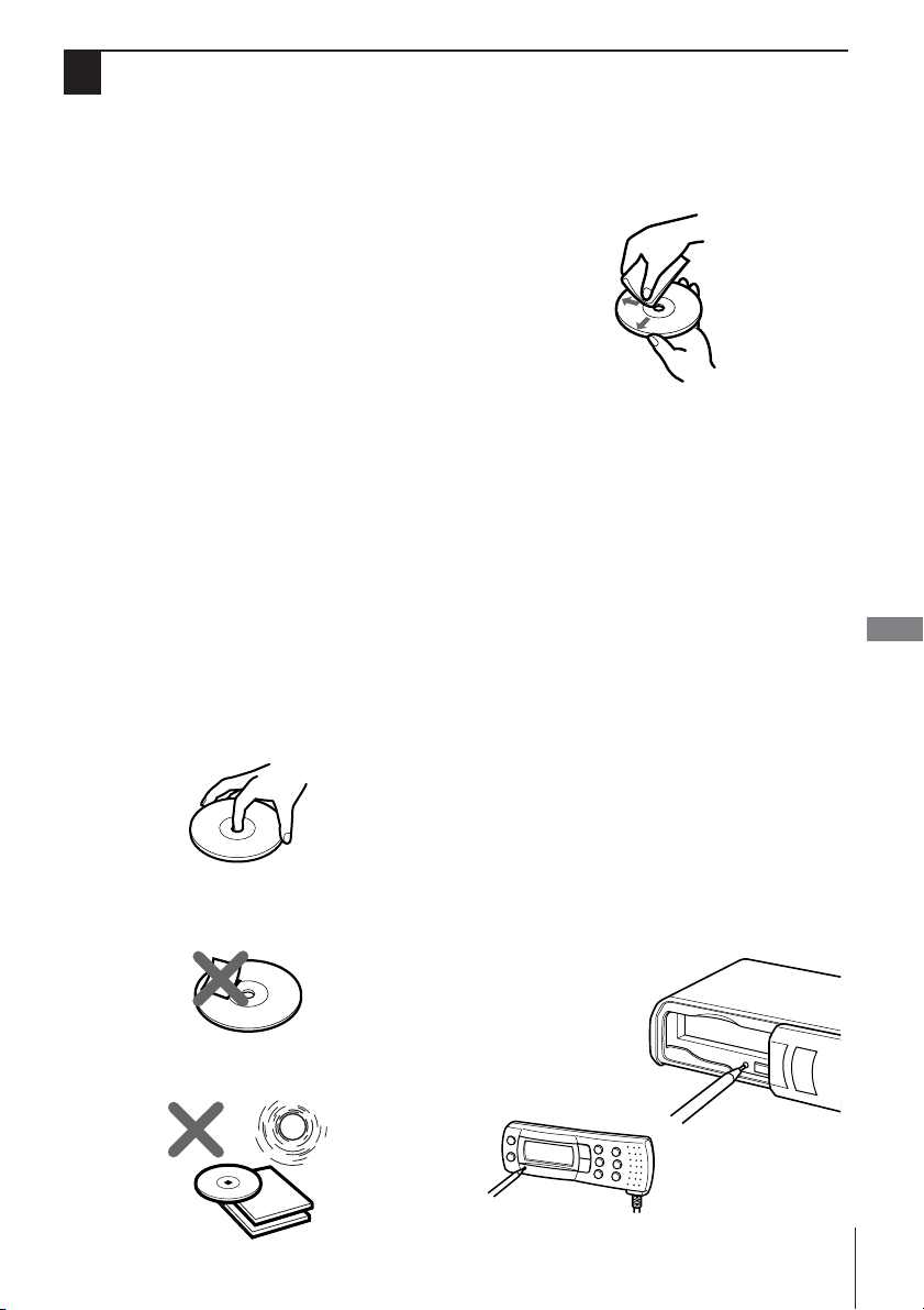
Notes on CDs
•A defective or soiled disc stored in the disc
magazine can cause the sound to drop out
during play.
•Always handle a disc by holding its inner and
outer edges.
•Do NOT touch the surface of the unlabeled side
of the disc.
•Do NOT attach paper or tape etc. to a disc.
•Clean the discs before inserting them into the
disc magazine. Always clean a disc from the
center outward with a cleaning cloth.
• NEVER use solvents such as benzine or alcohol
to clean a disc.
• You cannot play an 8-cm (3-inch) CD — even
with the specially designed adaptor.
Notes on the disc magazine
•Do NOT leave the disc magazine in a place
subject to excessive temperature or humidity.
•Do NOT insert more than one disc per slot.
•Do NOT drop the disc magazine.
ENGLISH
Reset buttons
The wired remote control and compact disc
changer each have a reset button. The compact
disc changer’s reset button is visible when the
disc magazine door is opened. Press either of
the buttons in the following cases:
•All the connections have been completed.
• The unit malfunctions. (For example, if the unit
does not load a CD properly.)
• An error code appears in the display window of
the wired remote control.
When you press this button, use the tip of a ballpoint pen or similar pointed object.
•Do NOT expose the discs to direct sunlight or
excessive heat.
EN
3
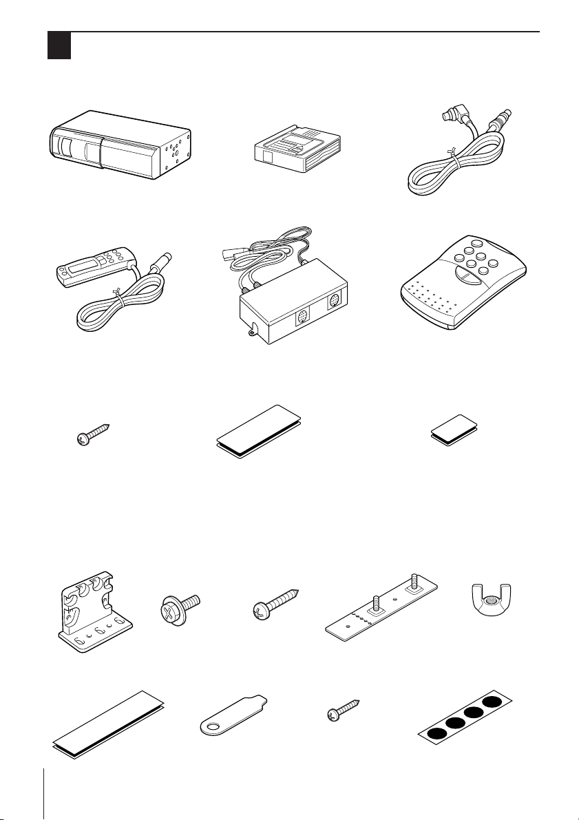
UNPACKING
1
Only for ADC-WRF35
2
Only for ADC-WRF35 and ADC-RF35
Compact disc changer
Wired remote control
Tapping screw
for the power unit &
FM modulator (2 ea.)
2
2
Compact disc magazine Connecting cable
2
Power unit & FM modulator
Double-back tape (medium)
for the wired remote control (1 set)
2
Wireless remote control
Double-back tape (small)
for the wireless remote control
(1 set)
Supplied mounting kit
for the compact disc changer
The letlers are keyed to those in the instructions.
Use only the supplied mounting hardware for safe and secure installation.
1
1
a Brackets (2 ea.)
EN
4
(large) (2 sets)
b Washer screws
(4 ea.)
g Key (1 ea.)f Double-back tape
c Tapping screws
(4 ea.)
h Tapping screws
d Plate brackets
(2 ea.)
(4 ea.)
e Wing nuts (4 ea.)
i Adhesive label (1 seet)
INSTALLATIONS
Precautions
Select the mounting location very carefully,
referring to the following points.
•Make sure that there is no fuel tank, wiring or
piping on the other side of the mounting surface.
•Make sure that the installation of the unit will not
hinder the movement of the deck lid or interfere
with the spare tire, etc.
•Use only the supplied mounting kit for safe and
proper installation.
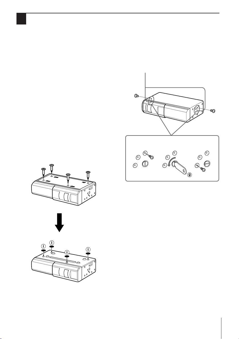
Removing the transport screws
Find the four transport screws at the bottom of the
unit, which lock the unit's mechanism during
transport. Remove these screws before
installation and attach the supplied adhesive
labels over the holes.
Retain these screws and replace them in the
original positions if the unit is transported for
service or maintenance.
Mounting angle setting dials
Be sure to change the position of the mounting
angle setting dials according to the angle at
which the unit is to be installed.
Mounting angle setting dial
132
H
5
4
V
For example, in relevance to the diagram above,
the following procedure would be used to change
the position from H (horizontal) to V (vertical).
H
5
4
V
H
5
4
V
1 Remove the locking screw.
2 Using the supplied key, turn the dial to the
position corresponding to the angle at which
the unit is to be installed.
H: Horizontal/suspended installation
45: 45° (slanted) installation
V: Vertical installation
3 Install the locking screw in the corresponding
hole.
4 Follow the same procedure for the other side
of the unit.
Note
• The mounting angle setting dials on each side of the
unit are factory-set to the H (horizontal) position.
EN
5
 Loading...