


AM-HX70 AHK
SERVICE MANUAL
MINIDISC PLAYER |
BASIC MD MECHANISM : AZG-F A |
|
|
•This Service Manual is the "Revision Publishing" and replaces "Simple Manual" AM-HX70<AHK> (S/M Code No. 09-006-435-8T1).
S/M Code No. 09-009-435-8R1
REVISION |
A |
T |
|
DA |
|
|
SPECIFICATIONS |
Main unit |
|
Playback system |
MiniDisc digital audio system |
Laser pickup |
Semiconductor laser |
Sampling Frequency |
44.1 kHz |
Number of channels |
Stereo: 2 channels |
|
Monaural: 1 channel |
D/A converter |
1-bit |
Frequency response |
40 to 20,000 Hz ± 4 dB |
Wow and Flutter |
20 to 20,000 Hz ± 1 dB (10 kΩ) |
Below measurable limit |
|
Output |
(±0.00 1% W.PEAK) |
Phone jack |
|
Maximum output level |
8 mW + 8 mW (16 Ω) |
Power requirements |
DC 1.2 V using the supplied NI-MH |
|
rechargeable battery MHB-901 |
|
DC 1.5 V using an LR6 (size AA) dry |
|
cell battery |
|
AC house current using an optional AC adaptor |
Battery life |
Using the supplied rechargeable battery |
|
Approx. 19 hours (with power save on: |
|
approx. 25 hours) |
|
Using an LR6 (size AA) dry cell battery |
|
Approx. 29 hours (with power save on: |
|
approx. 38 hours) |
|
Using the supplied rechargeable battery and an |
|
LR6 (size AA) dry cell battery |
|
Approx. 51 hours (with power save on: |
|
approx. 67 hours) |
Maximum outside |
Approx. 71.6 (W) X 13.5 (H) X 77.7 (D) mm |
dimensions |
(excluding projected parts and controls) |
Weight |
Approx. 60 g excluding batteries. |
<Battery charger RB-M02 K> |
|
Rated voltage |
AC 240 V, 50 Hz |
•Design and specifications are subject to change without notice.
•Dolby noise reduction manufactured under license from Dolby
Laboratories Licensing Corporation.
"DOLBY" and the double-D symbol 
 are trademarks of Dolby Laboratories Licensing Corporation.
– 2 –
PROTECTION OF EYES FROM LASER BEAM DURING SERVICING
This set employs laser. Therefore, be sure to follow carefully the instructions below when servicing.
WARNING!!
WHEN SERVICING, DO NOT APPROACH THE LASER EXIT WITH THE EYE TOO CLOSELY. IN CASE IT IS NECESSARY TO CONFIRM LASER BEAM EMISSION. BE SURE TO OBSERVE FROM A DISTANCE OF MORE THAN 30cm FROM THE SURFACE OF THE OBJECTIVE LENS ON THE OPTICAL PICK-UP BLOCK.
sCaution: Invisible laser radiation when open and interlocks defeated avoid
exposure to beam.
sAdvarsel: Usynlig laserståling ved åbning, når sikkerhedsafbrydere er ude af funktion. Undgå udsættelse for stråling.
VAROITUS!
Laiteen Käyttäminen muulla kuin tässä käyttöohjeessa mainitulla tavalla saataa altistaa käyt-täjän turvallisuusluokan 1 ylittävälle näkymättömälle lasersäteilylle.
VARNING!
Om apparaten används på annat sätt än vad som specificeras i denna bruksanvising, kan användaren utsättas för osynling laserstrålning, som överskrider gränsen för laserklass 1.
CAUTION
Use of controls or adjustments or performance of procedures other than those specified herin may result in hazardous radiation exposure.
ATTENTION
L’utillisation de commandes, réglages ou procédures autres que ceux spécifiés peut entraîner une dangereuse exposition aux radiations.
ADVARSEL
Usynlig laserståling ved åbning, når sikkerhedsafbrydereer ude af funktion. Undgå udsættelse for stråling.
This Compact Disc player is classified as a CLASS 1 LASER product.
The CLASS 1 LASER PRODUCT label is located on the rear exterior.
CLASS 1 LASER PRODUCT
KLASSE 1 LASER PRODUKT
LUOKAN 1 LASER LAITE
KLASS 1 LASER APPARAT
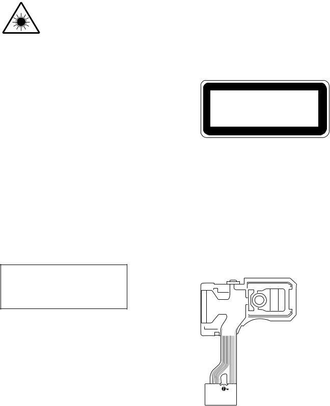
Precaution to replace Optical block
(KMS-330A)
PICK-UP Assy P.C.B
Body or clothes electrostatic potential could ruin laser diode in the optical block. Be sure ground body and workbench, and use care the clothes do not touch the diode.
1)After the connection, remove solder shown in right figure.
 Solder
– 3 –
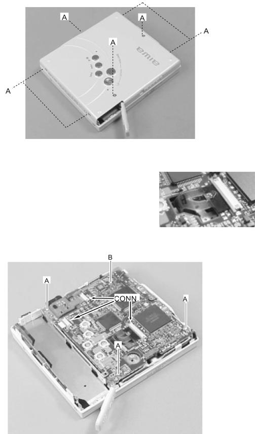
DISASSEMBLY INSTRUCTIONS
Disassembling and Notes on Reassembling
1.Removing the bottom panel
Remove the seven screws A. Open the battery lid and remove the bottom panel.
• Assemble the parts from the side of the headphone jack while being careful of the HOLD switch and battery lid.
2.Removing the main board
1)Short the short land of the pickup by soldering.
2)Remove the three connectors.
3)Remove three screws A and screw B.
4)While being careful of the FFC of the pickup, remove the main board.
•When assembling the parts, fasten the screws from screw B
and finally remove the short land of the pickup. |
Pickup short land |
– 4 –

3.Removing the Top Panel Remove the four screws A.
• When assembling the parts, the claws of the holder should be hooked on the arm (two claws).
4.Removing the center frame
Be careful not to contact the pickup during the following procedure.
1)Remove the bottom panel and top panel.
2)Remove the battery hinge block.
3)While bending the boss block of HLDR and CTRG, remove HLDR and CTRG in order of 1 and 2.
• When assembling the parts, insert the boss of HLDR and CTRG in order of 2 and 1.
4)Remove boss A from the center frame, and remove the center frame while lifting up the mechanism in the direction of the arrow.
3) HLDR, CTRG |
4) Center frame |
– 5 –
ELECTRICAL MAIN PARTS LIST
REF. NO. PART NO. |
KANRI |
DESCRIPTION |
|
NO. |
|
IC
87-A20-707-010
87-A21-608-010
8A-HM5-601-010
87-A21-724-040
87-A21-038-040
87-A21-575-010
87-A21-316-080
87-A20-861-040
87-A20-982-040
87-A21-627-040
87-A21-341-040
TRANSISTOR
89-115-884-080
87-A30-148-080
87-026-644-080
87-A30-261-080
87-A30-262-080
89-332-654-080
87-A30-147-080
87-A30-499-040
87-A30-033-080
DIODE
C-IC,CXA2523AR
C-IC,CXD2665GA C-IC,MSM66573L-047TB-9 C-IC,S-93C56AMFN C-IC,NJU7014R-TE2
C-IC,BD6606KVT
C-IC,S-8328B24MC
C-IC,S-80808ANNP
C-IC,S-80822ANNP
C-IC,XC6367B102MR
C-IC,TA2131FL
CHIP -TRANSISTER 2SA1588Y C-TR,2SC4738GR C-TR,DTA144EE C-FET,FDC633N C-FET,FDC634P
CHIP TRANSISTOR, 2SC3265Y C-TR,2SA1832GR C-FET,2SK2009 C-FET,2SK2035
|
87-A40-124-080 |
|
87-A40-687-080 |
|
87-017-850-080 |
MAIN C.B |
|
C100 |
87-A11-751-080 |
C102 |
87-A11-751-080 |
C103 |
87-A11-751-080 |
C104 |
87-A11-046-080 |
C106 |
87-A11-751-080 |
C107 |
87-A10-766-080 |
C108 |
87-A10-561-080 |
C109 |
87-A10-671-080 |
C110 |
87-A11-058-080 |
C111 |
87-A10-558-080 |
C112 |
87-A11-049-080 |
C113 |
87-A10-558-080 |
C114 |
87-A11-049-080 |
C115 |
87-016-448-080 |
C116 |
87-A10-543-080 |
C117 |
87-A10-561-080 |
C118 |
87-A10-561-080 |
C119 |
87-A10-671-080 |
C120 |
87-A10-559-080 |
C121 |
87-A10-766-080 |
C122 |
87-A10-561-080 |
C123 |
87-A10-561-080 |
C124 |
87-A10-554-080 |
C125 |
87-A10-554-080 |
C126 |
87-A10-554-080 |
C127 |
87-A10-554-080 |
C128 |
87-A10-554-080 |
C129 |
87-A10-554-080 |
C200 |
87-A11-751-080 |
C201 |
87-A10-770-080 |
C202 |
87-A10-770-080 |
C204 |
87-A10-902-080 |
C205 |
87-A10-770-080 |
C206 |
87-A10-550-080 |
C207 |
87-A10-902-080 |
C208 |
87-A10-561-080 |
C-DIODE,RB501V-40
C-DIODE,M1FH3
C-DIODE,DAP222
C-CAP,TN 22U-4 M P C-CAP,TN 22U-4 M P C-CAP,TN 22U-4 M P C-CAP,TN 100U-4 M F95 B C-CAP,TN 22U-4 M P
C-CAP,V 0.047-10 K B C-CAP,V 0.01U-16 K B C-CAP,V 0.022-16 K B C-CAP,U 0.22-10 K B C-CAP,V 4700P-25 K B
C-CAP,U 1-6.3 K B C-CAP,V 4700P-25 K B C-CAP,U 1-6.3 K B C-CAP,TN 2.2-10 F95P C-CAP,V 100P-50 J CH
C-CAP,V 0.01U-16 K B C-CAP,V 0.01U-16 K B C-CAP,V 0.022-16 K B C-CAP,V 6800P-25 K B C-CAP,V 0.047-10 K B
C-CAP,V 0.01U-16 K B C-CAP,V 0.01U-16 K B C-CAP,V 1000P-50 K B C-CAP,V 1000P-50 K B C-CAP,V 1000P-50 K B
C-CAP,V 1000P-50 K B C-CAP,V 1000P-50 K B C-CAP,V 1000P-50 K B C-CAP,TN 22U-4 M P C-CAP,V 0.1-10 K B
C-CAP,V 0.1-10 K B C-CAP,U 0.47-10 K B C-CAP,V 0.1-10 K B C-CAP,V 470P-50 K B C-CAP,U 0.47-10 K B
C-CAP,V 0.01U-16 K B
REF. NO. PART NO. |
KANRI |
DESCRIPTION |
|
NO. |
|
C209 |
87-A10-533-080 |
C210 |
87-A10-533-080 |
C216 |
87-A10-765-080 |
C217 |
87-A11-751-080 |
C219 |
87-A11-049-080 |
C220 |
87-A11-049-080 |
C301 |
87-A11-049-080 |
C302 |
87-A10-561-080 |
C303 |
87-A10-561-080 |
C304 |
87-A10-561-080 |
C305 |
87-A10-770-080 |
C306 |
87-A10-770-080 |
C308 |
87-010-787-080 |
C400 |
87-A10-556-080 |
C401 |
87-A10-770-080 |
C402 |
87-A10-770-080 |
C403 |
87-A11-046-080 |
C404 |
87-A10-591-080 |
C405 |
87-A11-049-080 |
C406 |
87-A11-049-080 |
C407 |
87-A10-902-080 |
C408 |
87-A10-765-080 |
C409 |
87-A10-765-080 |
C410 |
87-A10-556-080 |
C411 |
87-A10-556-080 |
C412 |
87-A10-556-080 |
C413 |
87-A10-556-080 |
C414 |
87-A10-556-080 |
C415 |
87-A10-770-080 |
C416 |
87-A11-751-080 |
C417 |
87-A11-807-080 |
C418 |
87-A11-058-080 |
C419 |
87-A11-058-080 |
C420 |
87-A11-058-080 |
C600 |
87-A11-806-080 |
C601 |
87-A10-557-080 |
C602 |
87-A11-806-080 |
C603 |
87-A10-770-080 |
C604 |
87-A10-770-080 |
C605 |
87-A10-554-080 |
C606 |
87-A11-807-080 |
C607 |
87-A11-049-080 |
C608 |
87-A10-547-080 |
C609 |
87-A10-537-080 |
C610 |
87-A11-751-080 |
C611 |
87-A11-049-080 |
C614 |
87-012-286-080 |
C701 |
87-A10-770-080 |
C702 |
87-A10-543-080 |
C703 |
87-A10-543-080 |
C704 |
87-A10-543-080 |
C705 |
87-A10-543-080 |
C706 |
87-A11-049-080 |
C707 |
87-016-449-080 |
C708 |
87-016-449-080 |
C709 |
87-A11-058-080 |
C710 |
87-A11-058-080 |
C711 |
87-A11-049-080 |
C712 |
87-A11-049-080 |
C713 |
87-A11-751-080 |
C715 |
87-A11-318-080 |
C716 |
87-A11-318-080 |
C717 |
87-A11-061-080 |
C720 |
87-A11-058-080 |
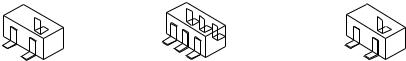
CN100 |
87-A61-315-080 |
CN401 |
87-A61-316-080 |
CN700 |
87-A61-317-080 |
D300 |
87-A40-556-080 |
L100 |
87-005-910-080 |
L102 |
87-A50-359-080 |
C-CAP,V 15P-50 J CH
C-CAP,V 15P-50 J CH
C-CAP,V 0.033-10 K B
C-CAP,TN 22U-4 M P
C-CAP,U 1-6.3 K B
C-CAP,U 1-6.3 K B
C-CAP,U 1-6.3 K B
C-CAP,V 0.01U-16 K B
C-CAP,V 0.01U-16 K B
C-CAP,V 0.01U-16 K B
C-CAP,V 0.1-10 K B
C-CAP,V 0.1-10 K B
CAP, U 0.022-25
C-CAP,V 2200P-50 K B
C-CAP,V 0.1-10 K B
C-CAP,V 0.1-10 K B C-CAP,TN 100U-4 M F95 B C-CAP,TN 47-6.3 M F95-BCASE C-CAP,U 1-6.3 K B
C-CAP,U 1-6.3 K B
C-CAP,U 0.47-10 K B
C-CAP,V 0.033-10 K B
C-CAP,V 0.033-10 K B
C-CAP,V 2200P-50 K B
C-CAP,V 2200P-50 K B
C-CAP,V 2200P-50 K B
C-CAP,V 2200P-50 K B
C-CAP,V 2200P-50 K B
C-CAP,V 0.1-10 K B
C-CAP,TN 22U-4 M P
C-CAP,TN 4.7U-6.3 M P C-CAP,U 0.22-10 K B C-CAP,U 0.22-10 K B C-CAP,U 0.22-10 K B C-CAP,TN 47U-6.3 M PSLB
C-CAP,V 3300P-25 K B C-CAP,TN 47U-6.3 M PSLB C-CAP,V 0.1-10 K B C-CAP,V 0.1-10 K B C-CAP,V 1000P-50 K B
C-CAP,TN 4.7U-6.3 M P C-CAP,U 1-6.3 K B C-CAP,V 220P-25 J CH C-CAP,V 33P-50 J CH C-CAP,TN 22U-4 M P
C-CAP,U 1-6.3 K B
C-CAP,U 0.01-25 KB
C-CAP,V 0.1-10 KB
C-CAP,V 100P-50 J CH
C-CAP,V 100P-50 J CH
C-CAP,V 100P-50 J CH
C-CAP,V 100P-50 J CH
C-CAP,U 1-6.3 K B
C-CAP,TN 10-4 F95 P
C-CAP,TN 10-4 F95 P
C-CAP,U 0.22-10 K B
C-CAP,U 0.22-10 K B
C-CAP,U 1-6.3 K B
C-CAP,U 1-6.3 K B
C-CAP,TN 22U-4 M P
C-CAP,TN 220U-2.5 SVB2 C-CAP,TN 220U-2.5 SVB2 C-CAP,S 2.2-10 K B C-CAP,U 0.22-10 KB C-CONN,20P H XF2L-2035
C-CONN,8P H XF2L-0835 C-CONN,8P H XF2L-0825 C-LED,CL-270HR RED C-COIL,S 22UH M LK2125 C-COIL, 22UH K NLFC252018
– 6 –

REF. NO. PART NO. |
KANRI |
DESCRIPTION |
|
NO. |
|
L200 |
87-A50-646-080 |
L400 |
87-A50-011-080 |
L401 |
87-A50-537-080 |
L402 |
87-A50-475-080 |
L403 |
87-A50-475-080 |
L404 |
87-A50-475-080 |
L405 |
87-A50-475-080 |
L406 |
87-005-910-080 |
L600 |
87-A50-325-080 |
L601 |
87-A50-012-080 |
L701 |
87-005-769-080 |
! PR600 |
87-A91-769-080 |
!PR601 87-A91-769-080
R204 |
87-A91-879-080 |
R211 |
87-A91-880-080 |
R314 |
87-A00-759-080 |
R315 |
87-A00-756-080 |
R320 |
87-A00-755-080 |
R321 |
87-A00-757-080 |
R322 |
87-A00-758-080 |
R323 |
87-A00-760-080 |
R618 |
87-A00-761-080 |
R619 |
87-A00-762-080 |
R701 |
87-A91-879-080 |
R702 |
87-A91-879-080 |
C-COIL, 22UH K NLFC201614 C-COIL,47UH LQH3C C-COIL, 100UH C4-K3L C-COIL, 10UH K NLFC201614 C-COIL, 10UH K NLFC201614
C-COIL, 10UH K NLFC201614 C-COIL, 10UH K NLFC201614 C-COIL,S 22UH M LK2125 C-COIL,180UH C4-K3L C-COIL,100UH LQH3C
C-COIL,S 100UH K C-PROTECTOR,0.75A ERY32SB075 C-PROTECTOR,0.75A ERY32SB075 C-F-BEAD, BK1608TS102 C-F-BEAD, BLM10A601SG
C-RES,V 27K-1/16W F
C-RES,V 10K-1/16W F
C-RES,V 6.8K-1/16W F
C-RES,V 12K-1/16W F
C-RES,V 22K-1/16W F
C-RES,V 68K-1/16W F C-RES,V 510K-1/16W F C-RES,V 680K-1/16W F C-F-BEAD, BK1608TS102 C-F-BEAD, BK1608TS102
REF. NO. PART NO. |
KANRI |
|
NO. |
R717 87-A91-878-080
R718 87-A91-878-080
R719 87-A91-878-080
S300 87-A91-436-080
S301 87-A90-703-080
S302 |
87-A90-232-080 |
S303 |
87-A90-232-080 |
S304 |
87-A90-232-080 |
S305 |
87-A90-232-080 |
S306 |
87-A90-232-080 |
X200 |
87-A70-276-080 |
X301 |
87-A70-277-080 |
DESCRIPTION
C-F-BEAD, BK1608HS241 C-F-BEAD, BK1608HS241 C-F-BEAD, BK1608HS241 C-SW,PUSH 2-1-1 SPVE3.8 C-SW,SL 1-1-3 SSSS813-B-2B
C-SW,TACT SKQRAA
C-SW,TACT SKQRAA
C-SW,TACT SKQRAA
C-SW,TACT SKQRAA
C-SW,TACT SKQRAA
C-VIB,CER 22.57MHZ CSACW2257MX C-VIB,CER 6.0MHZ CSTRC0600MG05
FLEX JACK C.B |
|
|
|
8A-HM5-602-010 |
PWB,FLEX JACK |
J700 |
87-A60-682-010 |
JACK,3.5 ST 7P |
 CHIP RESISTOR PART CODE
Chip Resistor Part Coding
8 8
A
Figure
Resistor Code
Value of resistor
Chip resistor
Wattage |
Type |
Tolerance |
Symbol |
Dimensions (mm) |
|
: A |
||
Form |
L |
W |
t |
Resistor Code : A |
||||
1/16W |
1005 |
5% |
CJ |
|
1.0 |
0.5 |
0.35 |
104 |
1/16W |
1608 |
5% |
CJ |
L |
1.6 |
0.8 |
0.45 |
108 |
t |
||||||||
1/10W |
2125 |
5% |
CJ |
W |
2 |
1.25 |
0.45 |
118 |
1/8W |
3216 |
5% |
CJ |
|
3.2 |
1.6 |
0.55 |
128 |
– 7 –
TRANSISTOR ILLUSTRATION
D |
D |
C |
D |
||
|
S |
|
G |
D |
B |
S |
D G |
E |
2SK2009 |
FDC633N |
2SA1588 |
2SK2035 |
FDC634P |
2SA1832 |
|
|
2SC3265 |
|
|
2SC4738 |
|
|
DTA144EE |
– 8 –

WIRING – 1 (MAIN) <1 / 2>
25 |
24 |
23 |
22 |
21 |
20 |
19 |
18 |
17 |
16 |
15 |
14 |
13 |
12 |
11 |
10 |
9 |
8 |
7 |
6 |
A
B
C
D
E
F
G
H
I
J
K
L
M
N
O
P
Q
R
S
T
U
TERMINAL DETAIL FIGURE
1 |
2 |
3 |
4 |
5 |
6 |
7 |
8 |
9 |
10 |
11 |
12 |
13 |
14 |
15 |
16 |
17 |
A3 142 139 137 133 130 126 124 121 118 116 112 110
B2 141 138 135 132 129 127 123 120 117 114 111 109
C |
5 |
4 |
|
140 136 134 131 128 125 122 119 115 113 108 |
|
106 107 |
|||||||||||
D |
7 |
6 |
1 |
|
|
|
|
|
|
|
|
|
|
|
103 104 105 |
||
E |
8 |
10 |
11 |
|
|
|
|
|
|
|
|
|
|
|
100 102 101 |
||
F |
9 |
13 |
12 |
|
|
|
|
|
|
|
|
|
|
|
97 |
98 |
99 |
G |
14 |
16 |
15 |
|
|
|
|
|
|
|
|
|
|
|
96 |
95 |
94 |
H |
17 |
19 |
18 |
|
|
|
|
IC200 |
|
|
|
|
92 |
91 |
93 |
||
|
|
|
|
|
|
|
|
|
|
|
|
|
|
|
|||
J |
20 |
|
|
|
|
|
|
|
|
|
|
|
|
|
88 |
89 |
90 |
K |
21 |
24 |
25 |
|
|
CXD2665GA TOP VIEW |
|
85 |
86 |
87 |
|||||||
|
|
|
|
|
|
|
|
|
|
|
|||||||
L |
22 |
23 |
26 |
|
|
|
|
|
|
|
|
|
|
|
82 |
83 |
84 |
M |
29 |
27 |
28 |
|
|
|
|
|
|
|
|
|
|
|
78 |
80 |
81 |
N |
30 |
31 |
32 |
|
|
|
|
|
|
|
|
|
|
|
76 |
77 |
79 |
P |
33 |
34 |
36 |
|
|
|
|
|
|
|
|
|
|
|
73 |
74 |
75 |
R |
143 |
35 |
147 144 37 |
46 |
47 |
50 |
53 |
56 |
59 |
64 |
68 146 |
|
72 |
145 |
|||
T |
|
|
38 |
40 |
42 |
45 |
48 |
51 |
55 |
57 |
60 |
63 |
66 |
67 |
70 |
|
|
U |
|
|
39 |
41 |
43 |
44 |
49 |
52 |
54 |
58 |
61 |
62 |
65 |
69 |
71 |
|
|
– 9 –

WIRING – 1 (MAIN) <2 / 2>
1 |
2 |
3 |
4 |
5 |
6 |
7 |
8 |
9 |
10 |
11 |
12 |
13 |
14 |
15 |
16 |
17 |
18 |
19 |
20 |
21 |
22 |
23 |
24 |
25 |
26 |
27 |
28 |
29 |
30 |
31 |
32 |
A
B
C
D
E
F
G
H
I
J
K
L
M
N
O
P
Q
R
S
T
U
– 10 –
SCHEMATIC DIAGRAM (MAIN / FLEX JACK)
– 11 –
 Loading...