


6ZG-1S
6ZG-1S2 6ZG-1S3
CD MECHANISM
• BASIC CD MECHANISM: 3ZG-2 E2 |
• TYPE: English |
BASIC NAME |
|
DERIVATION NAME |
||||
|
|
|
|
|
|
|
6ZG-1S |
D |
SH |
|
|
|
|
|
|
|
|
|
|
|
6ZG-1S2 |
D |
SH |
|
|
|
|
|
|
|
|
|
|
|
6ZG-1S3 |
D |
SH |
|
|
|
|
|
|
|
|
|
|
|
|
|
|
|
|
|
|
|
|
|
|
|
|
|
|
|
|
|
|
|
|

 This mechanism has various derivation. Derivation name is indicated by the Service Manual for eath model.
S/M Code No. 09-984-249-90T
TABLE OF CONTENTS |
|
PROTECTION OF EYES FROM LASER BEAM DURING SERVICING/ |
|
Precaution to replace Optical block......................................................................................................... |
3 |
SUFFIX NOTE ........................................................................................................................................ |
4 |
TRANSISTOR ILLUSTRATION .............................................................................................................. |
5 |
DISASSEMBLY INSTRUCTIONS ........................................................................................................ |
6-8 |
6ZG-1S |
|
ELECTRICAL MAIN PARTS LIST ................................................................................................................ |
9, 10 |
BLOCK DIAGRAM ...................................................................................................................................... |
11, 12 |
WIRING ....................................................................................................................................................... |
13, 14 |
SCHEMATIC DIAGRAM ............................................................................................................................. |
15, 16 |
IC DESCRIPTION ........................................................................................................................................ |
17-20 |
IC BLOCK DIAGRAM ....................................................................................................................................... |
21 |
TEST MODE ..................................................................................................................................................... |
22 |
MECHANICAL EXPLODED VIEW 1/1 .............................................................................................................. |
23 |
MECHANICAL PARTS LIST 1/1 ....................................................................................................................... |
24 |
CD MECHANISM EXPLODED VIEW/LIST (3ZG-1 E2) ................................................................................... |
25 |
6ZG-1S2 |
|
ELECTRICAL MAIN PARTS LIST .............................................................................................................. |
26, 27 |
IC BLOCK DIAGRAM ....................................................................................................................................... |
29 |
BLOCK DIAGRAM ...................................................................................................................................... |
30, 31 |
WIRING ....................................................................................................................................................... |
32, 33 |
SCHEMATIC DIAGRAM ............................................................................................................................. |
34, 35 |
IC DESCRIPTION ....................................................................................................................................... |
36, 37 |
6ZG-1S3 |
|
ELECTRICAL MAIN PARTS LIST .............................................................................................................. |
38, 39 |
BLOCK DIAGRAM ...................................................................................................................................... |
41, 42 |
WIRING ....................................................................................................................................................... |
43, 44 |
SCHEMATIC DIAGRAM ............................................................................................................................. |
45, 46 |
TEST MODE ..................................................................................................................................................... |
47 |
USE MODEL LIST ................................................................................................................................ |
48 |
2
PROTECTION OF EYES FROM LASER BEAM DURING SERVICING
This set employs laser. Therefore, be sure to follow carefully the instructions below when servicing.
WARNING!
WHEN SERVICING, DO NOT APPROACH THE LASER EXIT WITH THE EYE TOO CLOSELY. IN CASE IT IS NECESSARY TO CONFIRM LASER BEAM EMISSION. BE SURE TO OBSERVE FROM A DISTANCE OF MORE THAN 30cm FROM THE SURFACE OF THE OBJECTIVE LENS ON THE OPTICAL PICK-UP BLOCK.
Caution: Invisible laser radiation when open and interlocks defeated avoid exposure to beam.
Advarsel:Usynling laserståling ved åbning, når sikkerhedsafbrydere er ude af funktion. Undgå udsættelse for stråling.
VAROITUS!
Laiteen Käyttäminen muulla kuin tässä käyttöohjeessa mainitulla tavalla saattaa altistaa käyt-täjän turvallisuusluokan 1 ylittävälle näkymättömälle lasersäteilylle.
VARNING!
Om apparaten används på annat sätt än vad som specificeras i denna bruksanvising, kan användaren utsättas för osynling laserstrålning, som överskrider gränsen för laserklass 1.
CAUTION
Use of controls or adjustments or performance of procedures other than those specified herein may result in hazardous radiation exposure.
ATTENTION
L'utilisation de commandes, réglages ou procédures autres que ceux spécifiés peut entraîner une dangereuse exposition aux radiations.
ADVARSEL!
Usynlig laserståling ved åbning, når sikkerhedsafbrydereer ude af funktion. Undgå udsættelse for stråling.
This Compact Disc player is classified as a CLASS 1 LASER product.
The CLASS 1 LASER PRODUCT label is located on the rear exterior.
CLASS 1 LASER PRODUCT
KLASSE 1 LASER PRODUKT
LUOKAN 1 LASER LAITE
KLASS 1 LASER APPARAT
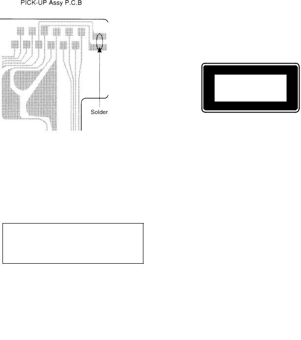
Precaution to replace Optical block
(KSS-213F)
Body or clothes electrostatic potential could ruin laser diode in the optical block. Be sure ground body and workbench, and use care the clothes do not touch the diode.
1)After the connection, remove solder shown in the right figure.
3

This is the SERVICE MANUAL for the BASIC CD MECHANISM of BASIC NAME: 6ZG- 1. This BASIC NAME includes the following models as shown under the SUFFIX name: DERIVATION NAME. Please use this manual with the separate SERVICE MANUAL for DERIVATION NAME.
BASIC CD MECHANISM: 6ZG-1 DSH
SUFFIX (DERIVATION NAME)
BASIC NAME: 6ZG-1S (SONY IC HIGH END MODEL) 6ZG-1S2 (The 2nd SONY IC MODEL) 6ZG-1S3 (The 3rd SONY IC MODEL)
BASIC NAME |
|
|
DERIVATION NAME |
|
|
|||
|
|
|
|
|
|
|
|
|
6ZG-1S |
D |
SH |
|
— |
— |
|
— |
— |
|
|
|
|
|
|
|
|
|
6ZG-1S2 |
D |
SH |
|
— |
— |
|
— |
— |
|
|
|
|
|
|
|
|
|
6ZG-1S3 |
D |
SH |
|
— |
— |
|
— |
— |
|
|
|
|
|
|
|
|
|
DERIVATION NAME
D:Digital output function
SH: Pick up equipped with shutter
4
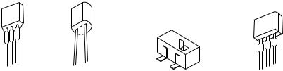
TRANSISTOR ILLUSTRATION
|
|
C |
|
|
E C B |
B |
|
E C B |
E |
B C E |
|
2SA933S |
2SA1015 |
2SA1235 |
2SB1329 |
DTC114ES |
2SC2001 |
2SC2412 |
|
|
2SD2172 |
2SC2712 |
|
|
2SD655 |
DTA114EK |
|
|
|
DTC114EK |
|
|
|
DTC114TK |
|
DTC123JK
DTC143TK
5
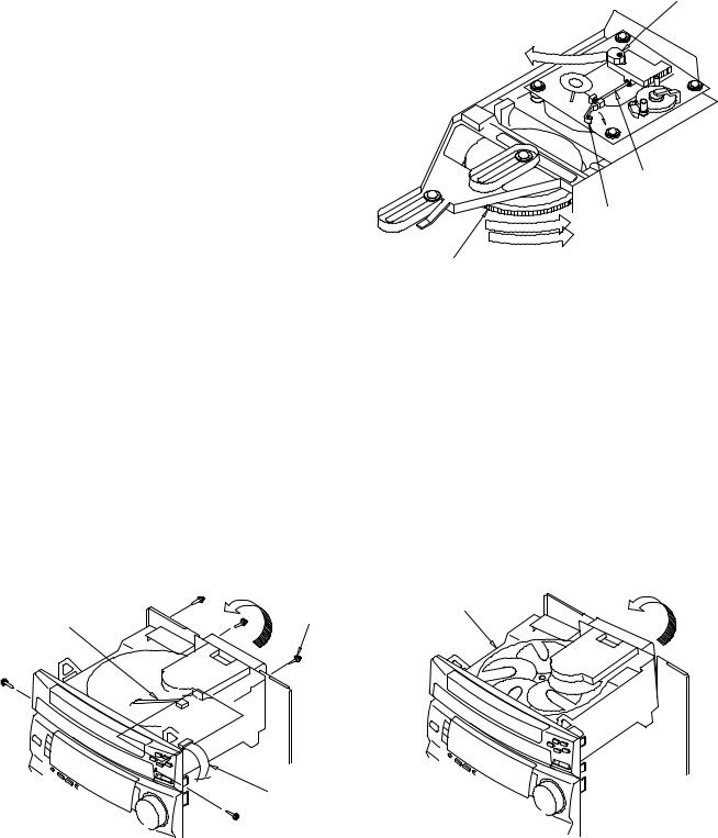
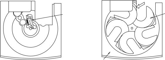
DISASSEMBLY INSTRUCTIONS
1.How to replace PICK UP.
1)Open the TRAY.
Push the stopper to arrow direction and release half of the SHAFT SLED.
2)Turn GEAR MAIN CAM to the counterclockwise (arrow “a”) direction, and lift up CD mechanism. (Fig-1)
3)Remove SHAFT SLED.
4)CD mechanism in down position, replace PICK UP.
5)Lift up CD mechanism (Fig-1), and Reassemble the SHAFT SLED.
PICKUP
|
SHAFT SLED |
|
STOPPER |
|
° |
GEAR MAIN CAM |
Fig-1 |
|
2.How to remove the 5CD CHANGER BLOCK (Fig-2)
1)Remove the two FFC of the CD circuit board, and remove the five SCREWS.
2)Lift 5 CD CHANGER BLOCK from behind, and remove it. (5CD CHANGER BLOCK can be removed even if PANEL TRAY is not removed.)
5CD CHANGER BLOCK
FFC |
SCREW |
|
LIFT UP |
||
|
FFC
Fig-2
6
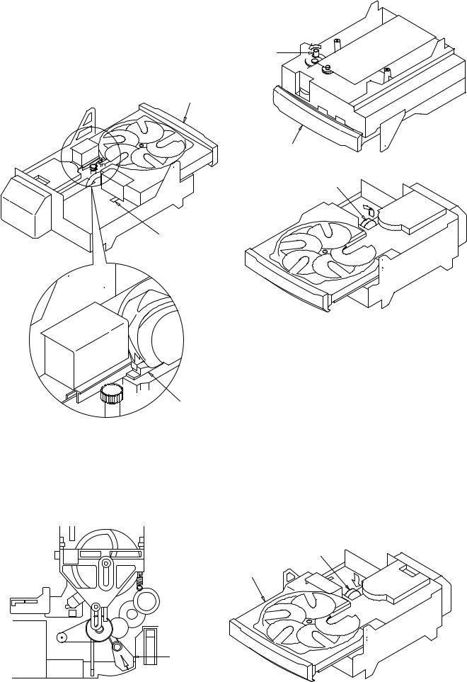
3.The disassemble and reassemble the TRAY
3-1. Disassembling procedure.
1)Push the PLATE GEAR’S Boss at the bottom part of CHAS MECHA strongly to the outside (arrow “b”
direction). (Fig-3) |
b |
|
(Confirm that TRAY appears a little in the front.) |
||
BOSS |
||
2) Draw TRAY to the open position. |
||
|
3)Remove FFC, and push the two LEVERS at both side of the CHAS MECH to remove TRAY. (Fig-4)
TRAY
5CD CHANGER BLOCK
FFC
LEVER
Fig-3
LEVER
Fig-4
3-2. Reassembling procedure.
1)Confirm that LEVER TRAY is at the most right position and check for the CD Mechanism to be in the down position. (Fig-5)
2)Push in the TRAY along the rail of the CHAS MECHA.
LEVER TRY
Fig-5
3)After TRAY is half closed and FFC is put in, it can enter by force until the end of TRAY closed. (Fig-6)
FFC
TRAY
Fig-6
7
4.How to reassemble the TURN TABLE. (Fig-7)
1)Push LEVER TT in the direction of “C”, and put in the TURN TABLE 5CD. (Fig-7)
After reassembly, one of the TURN TABLE DISC TRAY (can be either one of the five disc trays) must be aligned with TURN TABLE 5CD. (Fig-8)
That is, having no gap difference between the TURN TABLE 5CD and the TRAY 5CD.
*When reassembling the TURN TABLE 5CD, it is acceptable facing any CD number (1-5).
C |
LEVER TT |
|
ALIGN
TRAY 5CD
Fig-7 |
TURN TABLE 5CD |
Fig-8 |
8

MODEL NO. 6ZG-1S
ELECTRICAL MAIN PARTS LIST
REF. NO |
PART NO. |
KANRI |
DESCRIPTION |
|
|
NO. |
|
IC |
|
|
|
|
87-A20-547-010 |
C-IC,CXA1992AR |
|
|
87-A20-546-010 |
C-IC,CXD2589Q |
|
|
87-A20-592-040 |
C-IC,M51943 AML |
|
|
87-070-305-010 |
IC,BA6897S |
|
|
87-001-982-010 |
IC,TA7291S |
|
TRANSISTOR |
|
|
|
|
89-406-555-080 |
TR,2SD655 (0.5W) |
|
|
87-026-463-080 |
TR,2SA933S (0.3W) |
|
|
89-421-722-380 |
TR,2SD2172V/W |
|
|
89-320-011-080 |
TR,2SC2001 (15W) |
|
|
87-026-223-080 |
TR,DTC143TK |
|
|
89-110-155-080 |
TR,2SA1015(0.4W) |
|
|
87-026-608-080 |
C-TR,DTC 123 JK |
|
|
89-327-125-080 |
CHIP TR,2SC2712GR<D> |
|
DIODE |
|
|
|
|
87-020-465-080 |
DIODE,1SS133 (110MA) |
|
CD MAIN C.B |
|
|
|
C1 |
87-010-196-020 |
C-CAP,S 0.1-25 F |
|
C2 |
87-010-260-080 |
CAP, ELECT 47-25V |
|
C4 |
87-010-197-020 |
C-CAP,S 0.01-25 B |
|
C101 |
87-010-263-040 |
CAP,E 100-10 |
|
C102 |
87-010-178-020 |
C-CAP,S 1000P-50 B |
|
C103 |
87-010-550-040 |
CAP,E 100-6.3 GAS |
|
C104 |
87-010-182-020 |
C-CAP,S 2200P-50 B |
|
C105 |
87-010-198-020 |
C-CAP,S 0.022-25 B |
|
C106 |
87-016-081-020 |
C-CAP,S 0.1-16 RK |
|
C107 |
87-016-081-020 |
C-CAP,S 0.1-16 RK |
|
C108 |
87-016-081-020 |
C-CAP,S 0.1-16 RK |
|
C109 |
87-010-497-040 |
CAP,E 4.7-35 GAS |
|
C110 |
87-010-198-080 |
CAP, CHIP 0.022 |
|
C111 |
87-010-197-020 |
C-CAP,S 0.01-25 B |
|
C112 |
87-010-402-040 |
CAP,E 2.2-50 SME |
|
C113 |
87-010-382-040 |
CAP,E 22-25 SME |
|
C114 |
87-010-213-020 |
C-CAP,S 0.015-25 B |
|
C115 |
87-010-263-040 |
CAP,E 100-10 |
|
C116 |
87-010-197-020 |
C-CAP,S 0.01-25 B |
|
C117 |
87-016-369-020 |
C-CAP,S 0.033-25 B K |
|
C118 |
87-010-197-020 |
C-CAP,S 0.01-25 B |
|
C119 |
87-016-369-020 |
C-CAP,S 0.033-25 B K |
|
C120 |
87-010-197-020 |
C-CAP,S 0.01-25 B |
|
C121 |
87-010-494-040 |
CAP,E 1-50 GAS |
|
C122 |
87-010-154-020 |
C-CAP,S 10P-50 CH |
|
C123 |
87-010-154-020 |
C-CAP,S 10P-50 CH |
|
C124 |
87-010-154-020 |
C-CAP,S 10P-50 CH |
|
C125 |
87-010-596-020 |
C-CAP,S 0.047-16 RK |
|
C126 |
87-010-596-020 |
C-CAP,S 0.047-16 RK |
|
C127 |
87-012-140-020 |
C-CAP,S 470P-50 CH |
|
C128 |
87-010-596-020 |
C-CAP,S 0.047-16 RK |
|
C129 |
87-010-198-020 |
C-CAP,S 0.022-25 B |
|
C130 |
87-016-081-020 |
C-CAP,S 0.1-16 RK |
|
C131 |
87-010-550-040 |
CAP,E 100-6.3 GAS |
|
C132 |
87-010-550-040 |
CAP,E 100-6.3 GAS |
|
C133 |
87-012-158-020 |
C-CAP,S 390P-50 J CH |
|
C150 |
87-010-145-020 |
C-CAP,S 1P-50 C CH |
|
C202 |
87-010-596-020 |
C-CAP,S 0.047-16 RK |
|
C203 |
87-010-188-020 |
C-CAP,S 6800P-50 B |
|
C204 |
87-012-156-020 |
C-CAP,S 220P-50 CH |
|
C205 |
87-018-134-080 |
CAPACITOR,TC-U 0.01-16 |
|
C206 |
87-010-400-040 |
CAP,E 0.47-50 |
|
C207 |
87-010-197-020 |
C-CAP,S 0.01-25 B |
|
C208 |
87-010-318-020 |
C-CAP,S 47P-50 CH<D> |
|
C209 |
87-012-154-020 |
C-CAP,S 150P-50 J CH GRM |
|
REF. NO |
PART NO. |
KANRI |
DESCRIPTION |
|
|
|
|
NO. |
|
C210 |
87-012-154-020 |
C-CAP,S 150P-50 J CH GRM |
||
C211 |
87-010-176-020 |
C-CAP,S 680P-50 J SL |
||
C212 |
87-010-176-020 |
C-CAP,S 680P-50 J SL |
||
C213 |
87-010-382-040 |
CAP,E 22-25 SME<D> |
||
C213 |
87-010-401-040 |
CAP,E 1-50 SME |
||
C214 |
87-010-382-040 |
CAP,E 22-25 SME<D> |
||
C214 |
87-010-401-040 |
CAP,E 1-50 SME |
||
C215 |
87-010-318-020 |
C-CAP,S 47P-50 CH |
||
C216 |
87-010-318-020 |
C-CAP,S 47P-50 CH |
||
C217 |
87-010-380-040 |
CAP,E 47-16 SME |
||
C218 |
87-010-197-020 |
C-CAP,S 0.01-25 B |
||
C219 |
87-010-196-020 |
C-CAP,S 0.1-25 F |
||
C220 |
87-010-370-040 |
CAP,E 330-6.3 SME |
||
C221 |
87-010-197-020 |
C-CAP,S 0.01-25 B |
||
C222 |
87-010-186-020 |
C-CAP,S 4700P-50 B |
||
C223 |
87-016-081-020 |
C-CAP,S 0.1-16 RK |
||
C228 |
87-018-209-080 |
CAP, CER 0.1-50V |
||
C230 |
87-016-081-020 |
C-CAP,S 0.1-16 RK |
||
C231 |
87-018-209-080 |
CAP, CER 0.1-50V |
||
C401 |
87-010-403-080 |
CAP, ELECT 3.3-50V |
||
C402 |
87-010-403-040 |
CAP,E 3.3-50 SME |
||
C501 |
87-016-459-040 |
CAP,E 470-10 SMG |
||
C502 |
87-010-197-020 |
C-CAP,S 0.01-25 B |
||
C503 |
87-010-263-040 |
CAP,E 100-10 |
||
C504 |
87-010-196-020 |
C-CAP,S 0.1-25 F |
||
C505 |
87-010-196-020 |
C-CAP,S 0.1-25 F |
||
C506 |
87-010-196-020 |
C-CAP,S 0.1-25 F |
||
C507 |
87-010-196-020 |
C-CAP,S 0.1-25 F |
||
C508 |
87-016-459-040 |
CAP,E 470-10 SMG |
||
C509 |
87-010-196-020 |
C-CAP,S 0.1-25 F |
||
C510 |
87-010-196-020 |
C-CAP,S 0.1-25 F |
||
C601 |
87-010-197-020 |
C-CAP,S 0.01-25 B |
||
C602 |
87-016-251-040 |
CAP,E 220-16 SMG |
||
C603 |
87-010-196-020 |
C-CAP,S 0.1-25 F |
||
C701 |
87-010-322-020 |
C-CAP,S 100P-50 CH |
||
C702 |
87-010-318-020 |
C-CAP,S 47P-50 CH |
||
C703 |
87-010-318-020 |
C-CAP,S 47P-50 CH |
||
C705 |
87-010-178-020 |
C-CAP,S 1000P-50 B |
||
C706 |
87-018-199-080 |
CAP, CER 3300P |
||
C901 |
87-010-260-040 |
CAP,E 47-25 SME<D> |
||
C902 |
87-010-196-020 |
C-CAP,S 0.1-25 F<D> |
||
CN3 |
86-ZG1-609-010 |
CONN ASSY,6P |
||
FB1 |
87-003-223-080 |
FERRITE BEAD BL02RN2 |
||
FB2 |
87-003-223-080 |
FERRITE BEAD BL02RN2 |
||
FB3 |
87-003-223-080 |
FERRITE BEAD BL02RN2 |
||
FC1 |
86-ZG1-605-010 |
CABLE,FFC 16P |
||
FC2 |
86-ZG1-608-010 |
CABLE,FFC 8P |
||
L28 |
83-XM1-617-080 |
C-COIL,BK2125HM601 |
||
L41 |
83-XM1-617-080 |
C-COIL,BK2125HM601 |
||
L101 |
87-003-102-080 |
COIL, 10UH |
||
L201 |
87-003-102-080 |
COIL, 10UH |
||
LED901 |
87-A40-123-010 |
LED,SLZ-8128A-01-B<D> |
||
M601 |
87-045-305-010 |
MOTOR, RF-500TB DC-5V (2MA) |
||
!PR1 |
87-026-689-080 |
PROTECTOR,1A 60V 491 |
||
R101 |
87-022-363-020 |
C-RES,S 68K-1/10W F |
||
R102 |
87-022-363-020 |
C-RES,S 68K-1/10W F |
||
R103 |
87-022-363-020 |
C-RES,S 68K-1/10W F |
||
R104 |
87-022-363-020 |
C-RES,S 68K-1/10W F |
||
R105 |
87-022-365-020 |
C-RES,S 100K-1/10W F |
||
R106 |
87-022-365-020 |
C-RES,S 100K-1/10W F |
||
R420 |
87-029-060-080 |
RES,FUSE 33-1/4 W |
||
S601 |
87-036-109-010 |
PUSH SWITCH |
||
S602 |
87-036-109-010 |
PUSH SWITCH |
||
S603 |
87-036-109-010 |
PUSH SWITCH |
||
X201 |
87-A70-046-010 |
VIB,XTAL 16.934MHZ |
||
LED C.B |
|
|
|
|
LED701 |
87-017-733-080 |
LED,SEL1250SM |
||
LED702 |
87-017-350-080 |
LED,SEL1550CM |
||
9
REF. NO |
PART NO. |
KANRI |
DESCRIPTION |
|
|
|
|
NO. |
|
LED703 |
87-017-733-080 |
LED,SEL1250SM |
||
T-T C.B |
|
|
|
|
C411 |
87-018-214-080 |
CAP TC U 0.1-50F |
||
LED411 |
87-070-288-010 |
LED,GL380 |
|
|
M401 |
87-A90-036-010 |
MOT ASSY,RF-300CA-11 |
||
PS401 |
87-A90-156-010 |
SNSR,SG-240 |
||
Q411 |
87-A30-031-010 |
P-TR,PT380F |
||
S401 |
87-036-109-010 |
PUSH SWITCH |
||
•Regarding connectors, they are not stocked as they are not the initial order items.
The connectors are available after they are supplied from connector manufacturers upon the order is received.
|
|
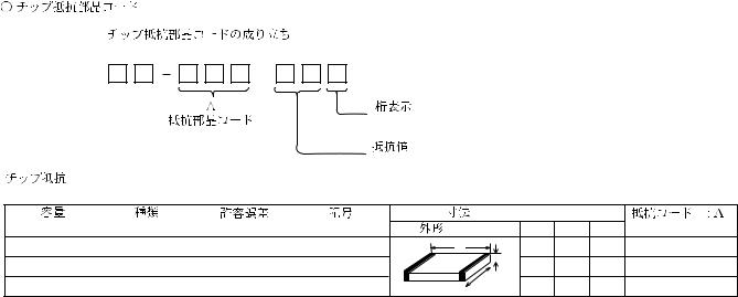
/ CHIP RESISTOR PART CODE |
|
|
|
|
|
|
|
|
|
|
|
|||
|
Chip Resistor Part Coding |
|
|
|
|
|
|
|
|
|
|
|
||||
8 |
8 |
|
|
|
|
|
|
|
|
|
|
|
|
|
|
|
|
|
|
|
|
|
|
Figure |
|
|
|
|
|
||||
|
|
|
Resistor Code |
|
|
|
|
|
|
|
|
|
|
|
||
|
|
|
|
|
|
|
Value of resistor |
|
|
|
|
|
||||
Chip resistor |
|
|
|
|
|
|
|
|
|
|
|
|
|
|
|
|
|
|
|
|
|
|
|
|
|
/ Diamensions (mm) |
|
|
|||||
|
|
|
|
|
|
|
|
|
|
|
||||||
Wattage |
|
Type |
|
Tolerance |
|
Symbol |
/ Form |
|
L |
W |
t |
Resistor Code : A |
||||
1/16W |
|
1608 |
|
5% |
|
CJ |
L |
1.6 |
0.8 |
0.45 |
108 |
|||||
|
|
2125 |
|
|
|
|
|
|
|
|
|
|
t |
1.25 |
0.45 |
118 |
1/10W |
|
|
5% |
|
CJ |
|
|
|
|
|
|
2 |
||||
|
|
|
|
|
|
|
|
|
|
|
|
|
|
|
|
|
1/8W |
|
3216 |
|
5% |
|
CJ |
|
|
|
W |
3.2 |
1.6 |
0.55 |
128 |
||
|
|
|
|
|
|
|
|
|
|
|
|
|
|
|
|
|
10
BLOCK DIAGRAM
|
RF |
11 |
12 |

WIRING
1 |
2 |
3 |
4 |
5 |
6 |
7 |
8 |
9 |
10 |
11 |
12 |
13 |
14 |
A
B
C
D
E
F
G
H
I
J
13 |
14 |
 Loading...