


B744V

17-118-02 rev. 02 04/12/11
Applications
• Bronze housing recommended for fiberglass or wood hulls only
Never install a bronze housing in a metal hull, because
electrolytic corrosion will occur.
• Never install a metal housing in a vessel with a positive ground
system.
Pre-test
After connecting the multisensor to the instrument, spin the
paddlewheel. Check for a speed reading and the approximate air
temperature.
Tools and Materials Needed
Fairing (optional)
Safety goggles
Dust mask
Water-based antifouling paint (mandatory in salt water)
Electric drill
Drill bit: 3mm or 1/8"
Hole saw:
Fiberglass or wood hull: 51mm or 2"
Sandpaper
Mild household detergent or weak solvent (alcohol)
Digital level (installation with fairing)
Band saw (installation with a fairing)
Rasp or power tool (installation with a fairing)
Marine sealant (suitable for below waterline)
Slip-joint pliers
Silicone grease or petroleum jelly (Vaseline
®
)
Zip-ties
Installation in a cored fiberglass hull:
Hole saw for hull interior: 60mm or 2-3/8"
Cylinder, wax, tape, and casting epoxy (see page 5, #5)
Identify Your Model
The model name is written on the top right corner of the paper tag
affixed to the cable.
Mounting Location
Acoustic Noise
Acoustic noise is always present and these sound waves can
interfere with the operation of the transducer. Background noise
from sources such as: waves, fish, rain, and other vessels cannot
be controlled. However, carefully selecting the multisensor’s
mounting location can minimize the effect of vessel generated
noise from the propeller(s) and shaft(s), other machinery, and
other echosounders. The lower the noise level, the higher the
echosounder gain that can be used.
Placement
Choose a location where:
• The water flowing across the hull is smoothest with a minimum
of turbulence and bubbles (especially at high speeds).
• The multisensor will be continuously immersed in water.
• The transducer beam is unobstructed by the keel or propeller
shaft(s).
• There is a minimum deadrise angle.
• There is adequate headroom inside the vessel for the height of
the housing, tightening the nuts, and removing the valve
assembly and insert.
Caution: Do not mount the multisensor in an area of turbulence or
bubbles such as:
Near water intake or discharge openings
Behind strakes, fittings, or hull irregularities
Behind eroding paint (an indication of turbulence)
B66V
B66V
Fairing
INSTRUCTIONSINSTALLATION
WARNING: NEVER USE SOLVENTS!
Cleaners, gasoline, paint, sealants and other products
may contain strong solvents, such as acetone, which
attack many plastics greatly reducing their strength.
IMPORTANT: Please read the instructions completely
before proceeding with the installation. These directions
supersede instructions in your instrument manual if they
differ.
TRIDUCER
®
Multisensor with Valve & Pin
Models: B744V, B744VL, B66V, B66VL
2
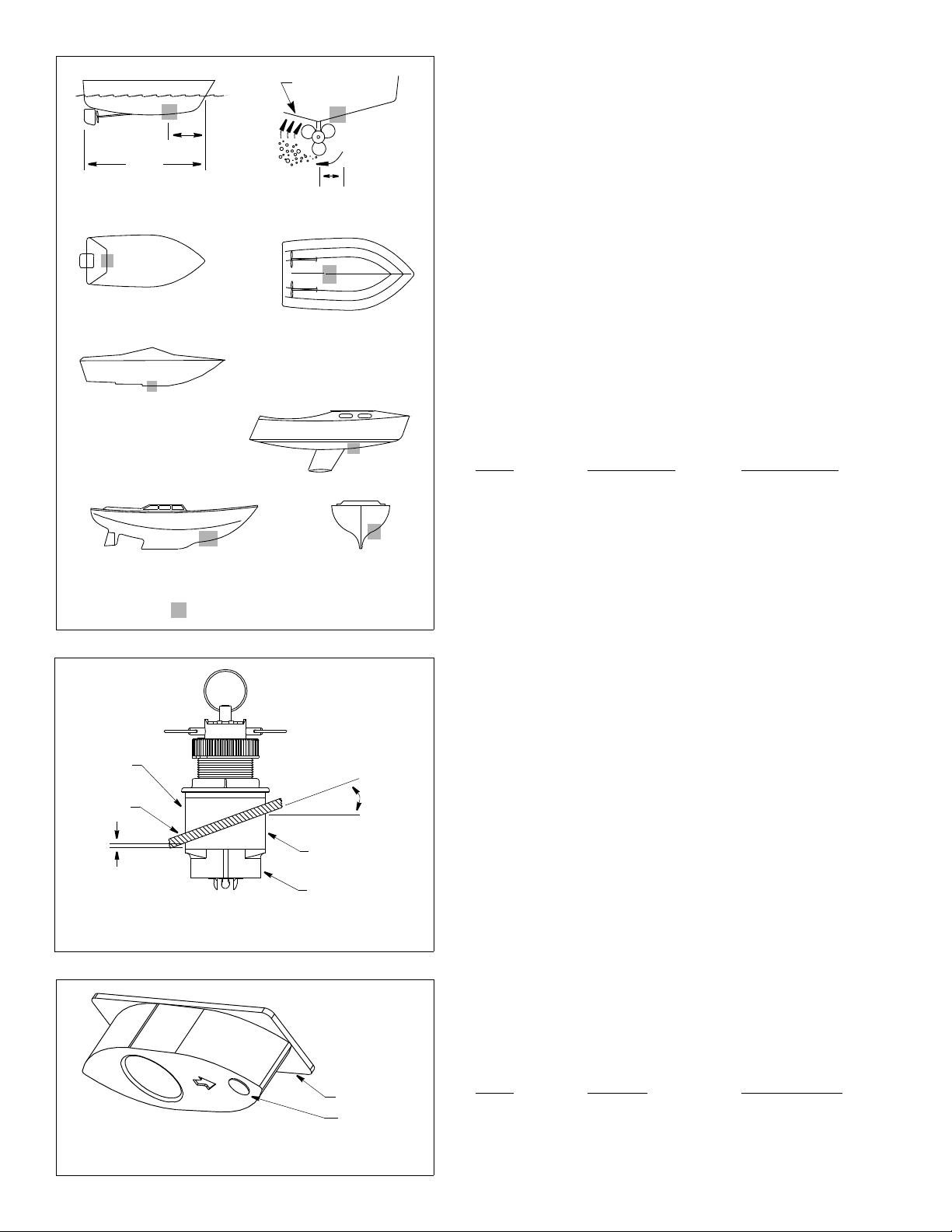
Boat Types (see Figure 1)
• Displacement hull powerboat—Locate 1/3 aft LWL and
150–300mm (6–12") off the centerline on the side of the hull where
the propeller is moving downward.
• Planing hull powerboat—Mount well aft, on or near the centerline,
and well inboard of the first set of lifting strakes to insure that it is in
contact with the water at high speeds. Mount on the side of the hull
where the propeller is moving downward.
Outboard and I/O—Mount just forward of the engine(s).
Inboard—Mount well ahead of the propeller(s) and shaft(s).
Step-hull—Mount just ahead of the first step.
Boats capable of speeds above 25 kn (29 MPH)—Review
multisensor location and operating results of similar boats before
proceeding.
• Fin keel sailboats—Mount to the side of the centerline and forward
of the fin keel 300–600mm (1–2').
• Full keel sailboats—Locate amidships and away from the keel at
the point of minimum deadrise angle.
Headroom
Allow adequate headroom inside the vessel for the height of the
housing, tightening the nuts and removing the insert.
Model Min. no fairing Min. with fairing
B744V 270mm (10
5
⁄8") 255mm (10")
B744VL 394mm (15
1
⁄2") 381mm (15")
B66V 270mm (10
5
⁄8") 255mm (10")
B66VL 394mm (15
1
⁄2") 381mm (15")
Preparation
Fairing
Nearly all vessels have some deadrise angle at the mounting location.
If the multisensor is mounted directly to the hull, the sound beam will
be tilted off the vertical at the same angle as the deadrise. A fairing is
strongly recommended if the deadrise angle exceeds 10°
(see Figure 2).
• Orients the sound beam straight down by mounting the multisensor
parallel to the water surface
• Minimizes aerated water flowing over the transducer’s face by
mounting it deeper in the water
• Reduces drag by directing the water around the multisensor
Airmar Urethane Fairing
Made of a high impact urethane with an integrated cutting guide, an
Airmar fairing is safer and easier to cut with a band saw and shape
with hand tools than custom fairings (see Figure 3). It can be shaped
to accommodate a deadrise angle of up to 25°. (For fairing part
numbers, see “Replacement Parts” on page 6.)
Backing Block
A backing block is used inside the hull to provide a level surface for the
hull nut to seat against. It is fabricated matching the interior deadrise
angle of the boat. After cutting an Airmar fairing, use the remaining
section with the cutting guide as the backing block (see Figure 2).
Hull Thickness (measured perpendicular to the waterline)
Model No fairing Max. with fairing
B744V 10–72mm (
3
⁄8–2
7
⁄8") 26 mm (1")
B744VL 35–133mm (1
3
⁄8–5
1
⁄4") 87mm (3
3
⁄8")
B66V 10–70 mm (
3
⁄8–2
3
⁄4") 25 mm (1")
B66VL 70–133 mm (2
3
⁄4–5
1
⁄4") 87 mm (3
3
⁄4")
inboard
Figure 1.
pressure waves
1/3 aft
full keel sailboat
displacement hull
(6– 12")
fin keel sailboat
150– 300 mm
LWL
Best location for the multisensor
(Load Waterline Length)
step-hull
outboard and I/O
planning hulls
cutting guide
button
Figure 3. Airmar urethane fairing (B66V shown)
BOW ►
6– 12 mm (1/4– 1/2")
backing
hull
fairing
multisensor
deadrise
fairing thickness
angle
slope of hull
parallel to
waterline
block
Figure 2. Deadrise angle & fairing thickness (B66V shown)
at narrowest point
 Loading...