


B744V
Junction Box Kit
INSTALLATION INSTRUCTIONS
for Replacement Speed/Temperature Insert
Models: B44V, B66VL, B744V, B744VC, B744VL, B744VLC
WARNING: Always wear safety goggles and a dust
mask when installing to avoid personal injury.
CAUTION: High Voltage Charge
The depth transducer may be storing a high voltage
charge. Accidental discharge could destroy the speed
sensor.
IMPORTANT: Read the instructions completely
17-033-02 rev. 07 12/14/10
before proceeding with the installation. These
instructions supersede any other instructions in your
instrument manual if they differ.
Applications
• These instructions are for a replacement speed/temperature
insert only. Installing a new insert will NOT solve problems with
depth sounding or fish finding.
• Determine which instructions to follow, either A or B, by looking
at your multisensor. If your multisensor has one cable, follow
instructions A on page 2. If your multisensor has two cables—
one from the depth transducer and one from the speed/
temperature insert—follow instructions B on page 3.
• If these instructions are followed carefully:
• The connections will not corrode
• The strain relief grommets will be water resistant and provide
excellent cable retention.
Before Installing
1. Be sure your new speed/temperature insert is the correct
replacement. Compare the length of the new insert with the
original insert (ignore the cable). If the new insert is more than
3mm (1/8") longer or shorter than the original insert, return it. To
obtain the correct insert, see “ Replacement Parts” on the back
of your multisensor’s owner’s guide.
2. Check the multisensor’s connector at the echosounder for
corrosion. If the connector’s pins are corroded, clean them.
Then test the multisensor to see if the problem has been
corrected.
3. Check the speed and temperature functions of the new insert.
Connect it to the echosounder and spin the paddlewheel.
Check for a reading of several knots. Check for the approximate
air temperature. If there is no reading(s), check the connection
and repeat the test. If there is still no reading(s) or it is
inaccurate, return the product to your place of purchase.
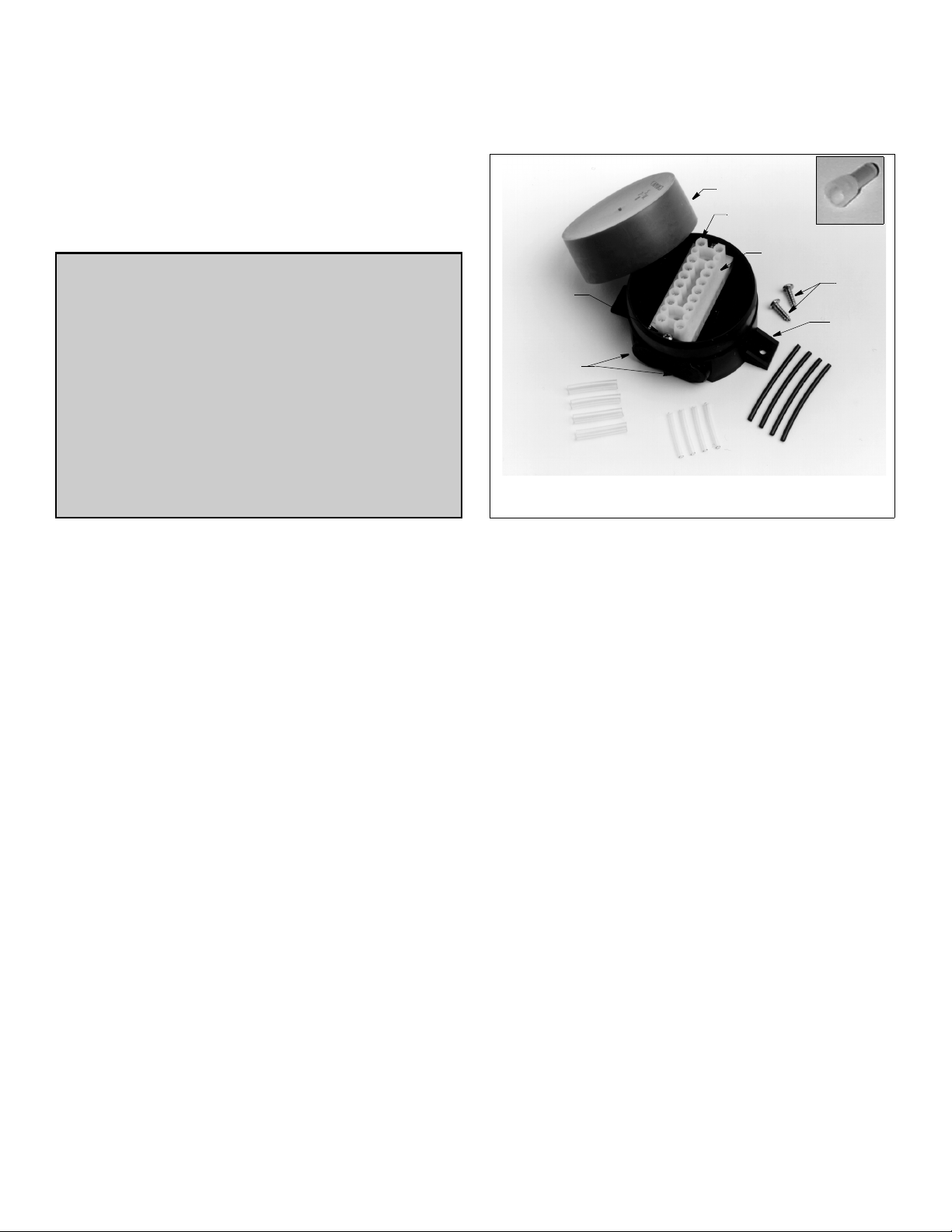
cap
terminal
block
screw (2)
grommet (4)
large diameter
sleeving
terminal screw
(16)
terminal block
mounting screws
small diameter
sleeving
Figure 1. Junction box and contents
Copyright © 2002, 2009 Airmar Techno logy Corp.
connector
mounting
screws
tab (2)
black sleeving
Tools & Materials
Safety goggles
Dust mask
Pencil
Drill
Drill bit: 3mm or 1/8"
Screwdrivers: Phillips and blade
Box-cutter knife (zip-cable installation)
Cutting pliers
Masking tape
Marker
Wire strippers
Alcohol
Crimping pliers (nine or ten-wire cables)
Anti-fouling paint (water-based) (mandatory in salt water)
Silicone lubricant or petroleum jelly
Mounting Location
1. Remove the red cap from the junction box and set the contents
aside (see Figure 1).
2. Select a convenient dry mounting location along the
multisensor’s cable route, preferably 1– 1.5 m (3–5') from the
multisensor but no more than 3m (10').
3. Position the junction box so the grommets are easily accessible
to the cable. Mark the location of the mounting holes.
4. At the marked location, drill two 3mm or 1/8" holes
approximately 10mm (3/8") deep. Do not fasten the junction
box in place at this time.
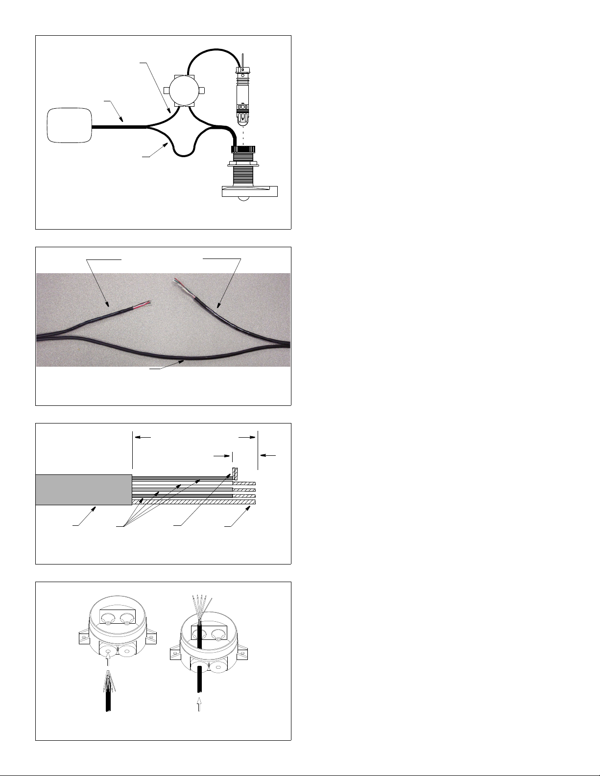
speed/temp half of zip-cable
Figure 4. Preparing the cables
cable
jacket
AIRMAR TRANSDUCER CABLE C344
colored
wires
bare
wire
folded
stripped end
Copyright © 2002, 2009 Airmar Techno logy Corp.
(contains red, green, brown,
echosounder
(printed half)
white, and bare wires)
zip-cable
depth-transducer
half of zip-cable
Figure 2. Splicing a zip-cable multisensor
Copyright © 2002, 2009 Airmar Tec hnology Corp.
zip-cable that is labeled
“Airmar Transducer Cable”
Cut the half of the
Preparing the Cables
C
3-5
5-75-7
insert
BA
multisensor
A. One Cable (Zip-cable) Multisensor
CAUTION: Do not cut the depth-transducer half of the zip-cable.
CAUTION: Do not puncture unused grommets.
1. Disconnect the multisensor from the echosounder.
2. On the junction box, use a small Phillips screwdriver to
puncture the center of both grommets marked 5-7 and one
grommet marked 3-5 (see Figure 2).
3. The multisensor’s cable is actually two separate cables joined
together. This type of cable is called zip-cable. Near the
mounting location of the junction box, separate the two halves of
the zip-cable. Carefully cut them apart with a box-cutter knife for
a distance of 0.5m (18"). Start at the junction box location and
move toward the sounder. Cut only the insulation between the
halves. DO NOT cut into the cables and expose the wires inside.
4. After you have separated the zip-cable, notice that one of the
halves is printed with the words “Airmar Transducer Cable” (see
Figure 3). The printed half of the zip-cable contains the speed
and temperature functions. Cut only the speed/temperature
half of the cable near the junction box. The wires inside will
be red and green. DO NOT cut the depth-transducer half of the
cable.
Figure 3. Cutting the speed/temperature half of a zip-cable
Figure 5. Pushing a cable through a grommet
2
Do not cut the
unmarked half
Copyright © 2002, 2009 Airmar Techn ology Corp.
remove outer jacket and foil shielding
5 -7
5 -7
Copyright © 2002, 2009 Airmar Tech nology Corp.
6cm (2 1/2")
5 -7
5 -7
13mm
(1/2")
NOTE: If the wires inside the cut-half of the cable are blue,
black, and orange, you have cut the depth-transducer side by
mistake. Now cut the speed/temp half of the zip-cable. Because
the depth-transducer cable has been cut, you will need to splice
it back together (see Figure 9). Puncture the center of the
remaining 3-5 grommet. Prepare the cut ends of the depthtransducer cable (see Figure 10). If you have a nine or ten wire
cable, use crimping pliers and the crimp connectors supplied.
Also use silicone lubricant or petroleum jelly to ease sliding
through the grommets.
5. Label the cables as follows with tape and a marker (see Figure 2).
• Cable A—cable to echosounder
• Cable B—cable to multisensor
• Cable C—new speed/temp insert cable
6. Cables A and B—Strip 6cm (2-1/2") of the outer jacket and foil
shield from the cut ends (see Figure 4).
7. Cable A—Strip 13mm (1/2") of insulation from the end of each
colored wire.
8. Cable B—Only the bare wire will be used. Cut-off all the colored
wires.
9. Bend the stripped wires of each cable back against its cable
jacket (see Figure 5). Apply alcohol to the cut end of each cable
jacket to ease sliding. (Do not use any other lubricant to ease
sliding. It will interfere with sealing the grommets.) Push about
20cm (8") of each cable through the appropriate grommet until
all the wires are inside the junction box (see Figure 2). Bend the
wires back to their original position (see Figure 5).
10.Slide a black sleeve over each bare wire and position it against
the cable jacket. For ease in holding the sleeves in place and
connecting to the terminals, fold the stripped ends of each wire
in half. Twist the ends and bend them 90
° (see Figure 4).
11.Go to “Connecting & Testing” on page 3 and follow the
instructions.
 Loading...