


OWNER’S GUIDE &
Thru-Hull, Depth
Transducer
Low Profile, Flush, and Retractable Models
01/26/11
|
WARNING: Always wear safety goggles and a dust |
|
rev. 11 |
mask when installing to avoid personal injury. |
|
WARNING: Immediately check for leaks when the |
||
-01 |
||
boat is placed in the water. Do not leave the boat |
||
17-006 |
||
unchecked for more than three hours. Even a small |
||
|
leak may allow considerable water to accumulate. |
|
|
WARNING: Retractable models—The O-rings must |
|
|
be intact and well lubricated to make a watertight seal. |
|
|
WARNING: Retractable models—Always attach the |
|
|
safety wire to prevent the insert or blanking plug from |
|
|
backing out in the unlikely event that the cap nut fails |
|
|
or is screwed on incorrectly. |
|
|
WARNING: B117 and P319—Do not use the spacer |
|
|
if there is insufficient space to tighten the nut or it is |
|
|
within 11mm (1/2") of the top of the housing. |
|
|
WARNING: Stainless steel housing in metal hull— |
|
|
Be sure the washer contacts the hull. Do not tighten |
|
|
the hull nut with the washer against the isolation |
|
|
bushing, as the housing will not be firmly installed. If |
|
|
necessary, sand the isolation bushing until the washer |
|
|
rests against the hull. |
|
|
CAUTION: Never pull, carry, or hold the transducer by |
|
|
its cable; this may sever internal connections. |
|
|
CAUTION: Never use solvents. Cleaners, fuel, |
|
|
sealants, paint, and other products may contain strong |
|
|
solvents, such as acetone, which attack many |
|
|
plastics, greatly reducing their strength. |
|
|
CAUTION: Plastic housing—Never use a fairing with |
|
|
a plastic housing; the protruding sensor would be |
|
|
vulnerable to damage from impact. |
|
|
CAUTION: Metal housing—Never install a metal |
|
|
housing on a vessel with a positive ground system. |
|
|
CAUTION: Stainless steel housing in metal hull— |
|
|
Stainless steel must be isolated from a metal hull to |
|
|
prevent electrolytic corrosion. Use the isolation |
|
|
bushing supplied. |
|
|
IMPORTANT: Read the instructions completely |
|
|
before proceeding with the installation. These |
|
|
instructions supersede any other instructions in your |
|
|
instrument manual if they differ. |
INSTALLATION INSTRUCTIONS
Record the information found on the cable tag for future reference.
Part No._________________Date___________Frequency________kHz
low profile |
|
|
|
|
retractable |
|
|
|
|
|
|
|
|
|
|
|
|
|
|
flush |
|
|
|||||||||||||||||||||||||||||||||||||||||||||||
|
|
|
|
|
|
|
|
|
|
|
|
|
|
|
|
|
|
|
|
||||||||||||||||||||||||||||||||||||||||||||||||||
P319 |
|
|
|
|
low profile |
|
|
|
|
|
|
|
|
|
|
|
|
|
|
|
|
|
|
|
|
|
|
|
|
|
|
|
|
|
|
P219 |
|
|
|||||||||||||||||||||||||||||||
|
|
|
|
|
|
|
|
|
|
|
|
|
|
|
|
|
|
|
|
|
|
|
|||||||||||||||||||||||||||||||||||||||||||||||
|
|
|
|
|
|
|
|
|
|
|
|
|
|
|
|
|
|
B17 |
|
|
|
|
|
|
|
|
|
|
|
|
|
|
|
|
|
|
|
|
|
|
|
|
|
|
|
|
|
|
|
|
|
|
|
|
|
|
|
|
|
|
|
||||||||
|
|
|
|
|
|
|
|
|
|
|
|
|
|
|
|
|
|
|
|
|
|
|
|
|
|
|
|
|
|
|
|
|
|
|
|
|
|
|
|
|
|
|
|
|
|||||||||||||||||||||||||
|
|
|
|
|
|
|
|
|
|
|
|
|
|
|
|
|
|
|
|
|
|
|
|
|
|
|
|
|
|
|
|
|
|
|
|
|
|
|
|
|
|
|
|
|
|
|
|
|
|
|
|
|
|
|
|
|
|
|
|
|
|
|
|
|
|
|
|
|
|
|
|
|
|
|
|
|
|
|
|
|
|
|
|
|
|
|
|
|
|
|
|
|
|
|
|
|
|
|
|
|
|
|
|
|
|
|
|
|
|
|
|
|
|
|
|
|
|
|
|
|
|
|
|
|
|
|
|
|
|
|
|
|
|
|
|
|
|
|
|
|
|
|
|
|
|
|
|
|
|
|
|
|
|
|
|
|
|
|
|
|
|
|
|
|
|
|
|
|
|
|
|
|
|
|
|
|
|
|
|
|
|
|
|
|
|
|
|
|
|
|
|
|
|
|
|
|
|
|
|
|
|
|
|
|
|
|
|
|
|
|
|
|
|
|
|
|
|
|
|
|
|
|
|
|
|
|
|
|
|
|
|
|
|
|
|
|
|
|
|
|
|
|
|
|
|
|
|
|
|
|
|
|
|
|
|
|
|
|
|
|
|
|
|
|
|
|
|
|
|
|
|
|
|
|
|
|
|
|
|
|
|
|
|
|
|
|
|
|
|
|
|
|
|
|
|
|
|
|
|
|
|
|
|
|
|
|
|
|
|
|
|
|
|
|
|
|
|
|
|
|
|
|
|
|
|
|
|
|
|
|
|
|
|
|
|
|
|
|
|
|
|
|
|
|
|
|
|
|
|
|
|
|
|
|
|
|
|
|
|
|
|
|
|
|
|
|
|
|
|
|
|
|
|
|
|
|
|
|
|
|
|
|
|
|
|
|
|
|
|
|
|
|
|
|
|
|
|
|
|
|
|
|
|
|
|
|
|
|
|
|
|
|
|
|
|
|
|
|
|
|
|
|
|
|
|
|
|
|
|
|
|
|
|
|
|
|
|
|
|
|
|
|
|
|
|
|
|
|
|
|
|
|
|
|
|
|
|
|
|
|
|
|
|
|
|
|
|
|
|
|
|
|
|
|
|
|
|
|
|
|
|
|
|
|
|
|
|
|
|
Applications
•Plastic housing recommended for fiberglass or metal hull only. Never install a plastic transducer in a wood hull, since swelling of the wood can possibly fracture the plastic.
•Bronze housing recommended for fiberglass or wood hull. Never install a bronze housing in an aluminum hull, because electrolytic corrosion will occur.
•Stainless steel housing compatible with all hull materials. Recommended for aluminum hull to prevent electrolytic corrosion provided the stainless steel housing is isolated from the metal hull.
•Accommodates up to a 20° deadrise angle.
Tools & Materials
Safety goggles
Dust mask
Electric drill with 10mm (3/8") or larger chuck capacity
Drill bit: |
3mm or 1/8" |
Hole saw (see table opposite) |
|
Countersink tool (installing a flush housing) |
|
Sandpaper |
|
Mild household detergent or weak solvent (such as alcohol) File (installation in a metal hull)
Marine sealant (suitable for below waterline)
Additional washer [for aluminum hull less than 6mm (1/4") thick] Slip-joint pliers (installing a metal housing)
Grommet(s) (some installations) Cable ties
Water-based anti-fouling paint (mandatory in salt water) Installation in a cored fiberglass hull (see page 4):
Hole saw for hull interior: (see table on this page) Fiberglass cloth and resin
or Cylinder, wax, tape, and casting epoxy
Identify Your Model
The model name is printed on the cable tag.
|
|
|
|
|
|
Model |
Minimum |
Outside Hull |
Cored Fiberglass Hull |
||
Hull Interior |
|||||
(Housing) |
Headroom |
Hole Saw Size |
|||
Hole Saw Size |
|||||
|
|
|
|
||
Low Profile: |
|
|
|
|
|
B22, B117, |
95 mm (3-3/4") |
51 mm or 2" |
60 mm or 2-3/8" |
||
P19, P319 |
|
|
|
|
|
|
|
|
|
|
|
P5 |
161mm 6-3/8”) |
51 mm or 2" |
60 mm or 2-3/8" |
||
|
|
|
|
|
|
Flush: |
100 mm (4") |
51 mm or 2" |
60 mm or 2-3/8" |
||
B21, P219, P269 |
|||||
|
|
|
|
||
|
|
|
|
|
|
Retractable: |
|
|
|
|
|
B17, B21 |
200 mm (8") |
51 mm or 2" |
60 mm or 2-3/8" |
||
P17, P217, P314 |
|
|
|
|
|
|
|
|
|
|
|
|
|
|
51 mm or 2" |
|
|
Retractable: |
200 mm (8") |
in a fiberglass or |
60 mm or 2-3/8" |
||
wood hull |
|||||
SS577 |
|||||
|
|
57 mm or 2-1/4" |
|
||
|
|
|
|
||
|
|
|
in a metal hull |
|
|
|
|
|
|
|
|
large displacement hulls |
small displacement hulls |
|
|
|
|
|
|
planing hulls |
outboard and I/O |
|
stepped hull |
|
|
|
fin keel sailboats |
|
|
|
|
full keel sailboats |
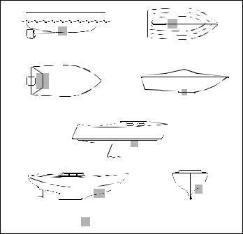
Figure 1. |
Best location for transducer |
|
Copyright © 2005 Airmar Technology Corp. |
||
Mounting Location
CAUTION: Do not mount near water intake or discharge openings or behind strakes, fittings, or hull irregularities.
•The water flowing under the hull must be smooth with a minimum of bubbles and turbulence (especially at high speeds).
•The transducer must be continuously immersed in water.
•The transducer beam must be unobstructed by the keel or propeller shaft(s).
•Choose a location away from interference caused by power and radiation sources such as: the propeller(s) and shaft(s), other machinery, other echosounders, and other cables. The lower the noise level, the higher the echosounder gain setting that can be used.
•Choose a location with a minimal deadrise angle, so the transducer beam will be aimed at the bottom.
•Choose an accessible spot inside the vessel with adequate headroom for the height of the housing, tightening the nuts, and removing any insert (see the table below).
Hull Types (see Figure 1)
•Displacement hull powerboats—Locate amidships near the centerline. The starboard side of the hull where the propeller blades are moving downward is preferred.
•Planing hull powerboats—Mount well aft, on or near the centerline, and well inboard of the first set of lifting strakes to ensure that the transducer will be in contact with the water at high speeds. The starboard side of the hull where the propeller blades are moving downward is preferred.
Outboard and I/O—Mount just forward of the engine(s). Inboard—Mount well ahead of the propeller(s) and shaft(s). Stepped hull—Mount just ahead of the first step.
Boat capable of speeds above 25kn (29MPH)—Review the installation location and operating results of similar boats before proceeding.
•Fin keel sailboats—Mount on or near the centerline and forward of the fin keel 300–600mm (1–2').
•Full keel sailboats—Locate amidships and away from the keel at the point of minimum deadrise.
Installation
Hole Drilling
Cored fiberglass hull—Follow separate instructions on page 4.
1.Drill a 3 mm or 1/8" pilot hole from inside the hull. If there is a rib, strut, or other hull irregularity near the selected mounting location, drill from the outside.
2.Using the appropriate size outside hull hole saw, cut a hole perpendicular to the hull from outside the boat (see table on page 1). Flush housing—Use a countersink tool to make a “seat” in the hull.
3.Sand and clean the area around the hole, inside and outside, to ensure that the marine sealant will adhere properly to the hull. If there is any petroleum residue inside the hull, remove it with either mild household detergent or a weak solvent (alcohol) before sanding.
Metal hull—Remove all burrs with a file and sandpaper.
Bedding
CAUTION; Be sure the surfaces to be bedded are clean and dry.
Apply a 2mm (1/16") thick layer of marine sealant around the flange of the housing that will contact the hull and up the sidewall of the housing (see Figure 2). The sealant must extend 6mm (1/4") higher than the combined thickness of the hull, washer, any spacer, and the hull nut. This will ensure there is sealant in the threads to seal the hull and to hold the hull nut securely in place.
Stainless steel housing in a metal hull—The stainless steel housing must be isolated from the metal hull to prevent electrolytic corrosion. Slide the isolation bushing onto the housing (see Figure 3). Apply additional marine sealant to the surfaces of the bushing that will contact the hull, filling any cavities in and around the bushing.
Installing
NOTE: Ignore any arrows on the housing, insert, and blanking plug.
1.From outside the hull, push the housing into the mounting hole using a twisting motion to squeeze out excess marine sealant.
2.From inside the hull, slide the washer onto the housing (see Figure 2).
B117 and P319—Also slide the spacer onto the housing and rest it against the washer. Do not use the spacer if there is insufficient space to tighten the nut or it is within 11mm (1/2") of the top of the housing.
Aluminum hull less than 6mm (1/4") thick—If necessary, use an additional rubbery, fiberglass, or plastic washer. Never use bronze since electrolytic corrosion will occur. Never use wood since it will swell, possibly fracturing the plastic housing.
Stainless steel transducer in metal hull—Be sure the washer contacts the hull. Do not tighten the hull nut with the washer against the isolation bushing, as the housing will not be firmly installed. If necessary, sand the isolation bushing until the washer rests against the hull (see Figure 3).
3.Screw the hull nut in place.
Plastic housing—If your housing has wrenching flats, do not clamp tightly possibly causing the housing to fracture.
Plastic hull nut—Hand tighten only. Do not over tighten.
Metal hull nut—Tighten with slip-joint pliers.
Cored Fiberglass Hull—Do not over tighten, crushing the hull. Wood hull—Allow the wood to swell before tightening the hull nut.
4.Remove any excess marine sealant on the outside of the hull to ensure smooth water flow over the transducer.
2
 Loading...