


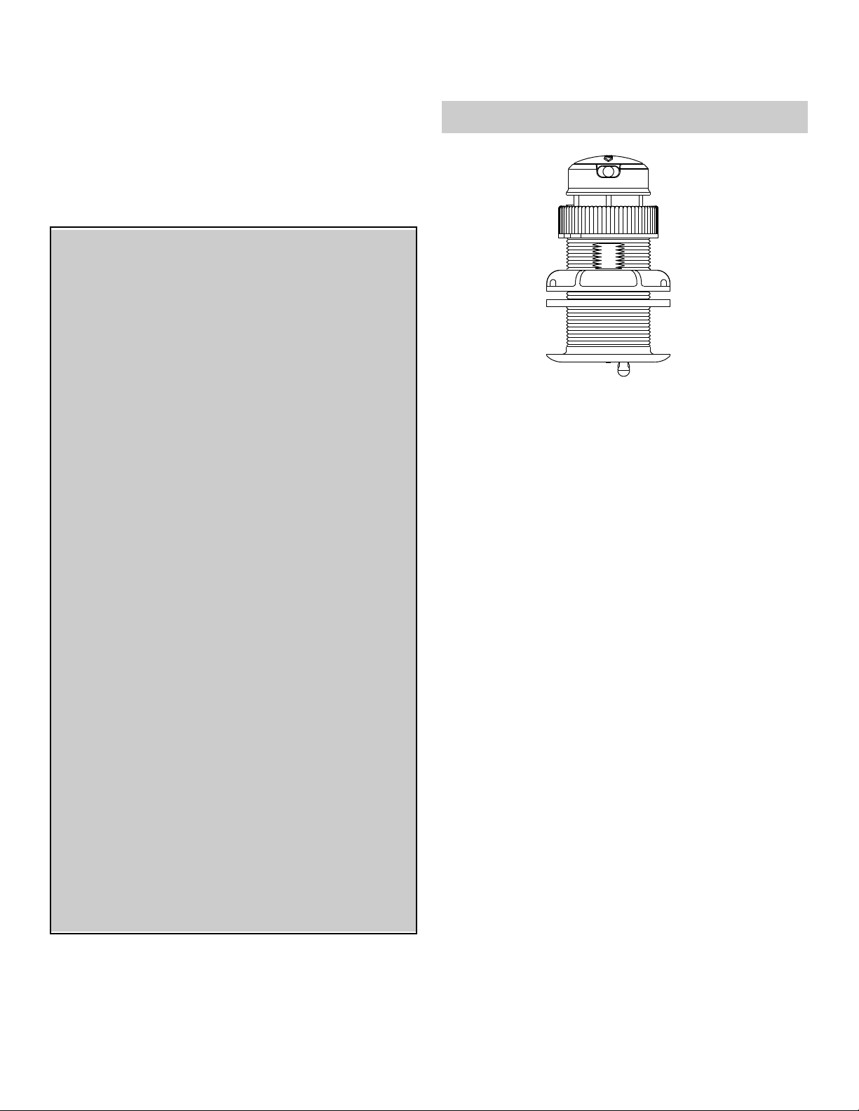
DST800
Applications
• Plastic housing recommended for fiberglass or metal hull only.
Never install a plastic housing in a wood hull since swelling of
the wood may overstress the plastic causing a fracture.
• Bronze housing recommended for fiberglass or wood hull.
Never mount a bronze housing in an aluminum hull because
electrolytic corrosion will occur.
• Stainless steel housing compatible with all hull materials.
Recommended for aluminum hull to prevent electrolytic corrosion
provided the stainless steel housing is isolated from the metal
hull.
• Accommodates up to 22° deadrise angle
Tools & Materials
Safety goggles
Dust mask
Water-based anti-fouling paint (mandatory in salt water)
Electric drill with 10mm (3/8") or larger chuck capacity
Drill bit: 3mm or 1/8"
Hole saw: 51mm or 2"
(plastic or metal housing in non-metal hull)
57mm or 2-1/4" (stainless steel housing in a metal hull)
Countersink tool (installing a flush housing)
Sandpaper
Mild household detergent or weak solvent (such as alcohol)
File (installation in a metal hull)
Marine sealant (suitable for below waterline)
Additional washer [for aluminum hull less than 6mm (1/4") thick]
Slip-joint pliers (installing a bronze housing)
Grommet(s) (some installations)
Cable ties
Installation in a cored fiberglass hull (see page 3):
Hole saw for hull interior: 60mm or 2-3/8"
Fiberglass cloth and resin
or Cylinder, wax, tape, and casting epoxy
17-355-01 rev. 06 12/14/10
Thru-Hull, Retractable
TRIDUCER
®
Multisensor
Model DST800
U.S. Patents: 6,904,798; 7,110,908; 7,352,171. UK Patents: 2 407 874; 2 409 527
Record the information found on the cable tag for future reference.
Part No._________________Date___________Frequency________kHz
plastic
low profile
P17 housing
INSTALLATION INSTRUCTIONSOWNER’S GUIDE &
Pretest
Connect the multisensor to the instrument and spin the
paddlewheel. Check for a speed reading and the approximate air
temperature. If there are no readings or they are inaccurate, check
all the connections and repeat the test. If there are still no readings
or they are inaccurate, return the product to the place of purchase.
WARNING: Always wear safety goggles and a dust
mask when installing to avoid personal injury.
WARNING: The O-rings must be intact and well
lubricated to make a watertight seal.
WARNING: Always attach the safety wire to prevent
the insert or blanking plug from backing out in the
unlikely event that the cap nut fails or is screwed on
incorrectly.
WARNING: Immediately check for leaks when the
boat is placed in the water. Do not leave the boat
unchecked for more than three hours. Even a small
leak may allow considerable water to accumulate.
WARNING: Stainless steel housing in a metal hull—
Be sure the washer contacts the hull. Do not tighten
the hull nut with the washer against the isolation
bushing, as the housing will not be firmly installed. If
necessary, sand the isolation bushing until the washer
rests against the hull.
CAUTION: Never install a metal multisensor on a
vessel with a positive ground system.
CAUTION: Never use a fairing with a plastic housing;
the protruding sensor would be vulnerable to damage
from impact.
CAUTION: Never pull, carry, or hold the multisensor
by its cable; this may sever internal connections.
CAUTION: Never use solvents. Cleaners, fuel,
sealants, paint, and other products may contain strong
solvents, such as acetone, which attack many
plastics, greatly reducing their strength.
CAUTION: Stainless steel housing must be isolated
from a metal hull to prevent electrolytic corrosion. Use
the isolation bushing supplied.
IMPORTANT: Read the instructions completely
before proceeding with the installation. These
instructions supersede any other instructions in your
instrument manual if they differ.
Mounting Location
CAUTION: Do not mount near water intake or discharge
openings, or behind strakes, fittings, or hull irregularities.
• The water flowing under the hull must be smooth with a
minimum of bubbles and turbulence (especially at high speeds).
• The multisensor must be continuously immersed in water.
• The transducer beam must be unobstructed by the keel or
propeller shaft(s).
• Choose a location away from interference caused by power and
radiation sources such as: the propeller(s) and shaft(s), other
machinery, other echosounders, and other cables. The lower
the noise level, the higher the echosounder gain setting that
can be used.
• Choose a location with a minimal deadrise angle, so the
transducer beam will be aimed at the bottom.
• Choose an accessible spot inside the vessel with adequate
headroom for the height of the housing, tightening the nuts, and
removing the insert. Allow a minimum of 280mm (11").
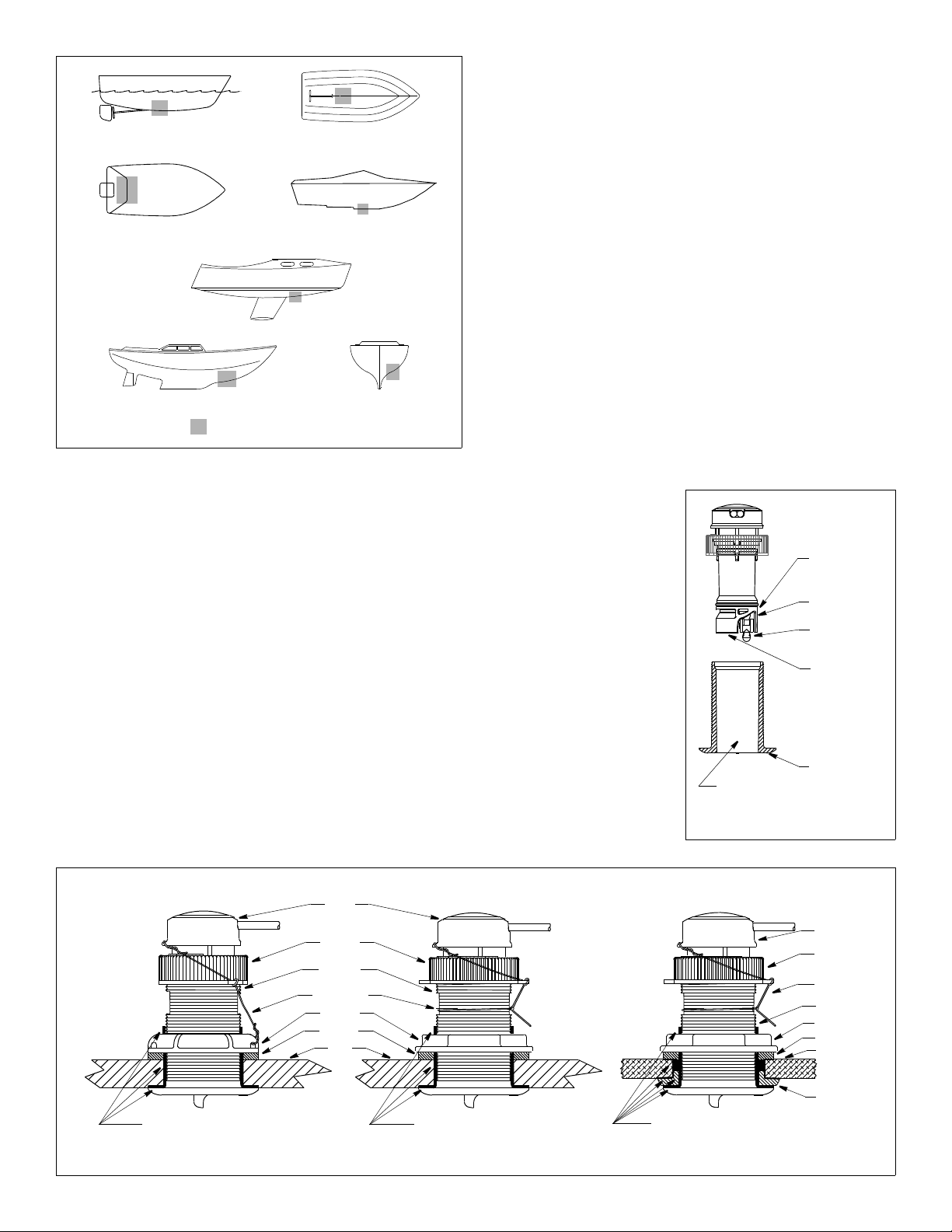
Hull Types (see Figure 1)
• Displacement hull powerboats—Locate amidships near the
centerline. The starboard side of the hull where the propeller blades
are moving downward is preferred.
• Planing hull powerboats—Mount well aft, on or near the centerline,
and well inboard of the first set of lifting strakes to insure that the
multisensor will be in contact with the water at high speeds. The
starboard side of the hull where the propeller blades are moving
downward is preferred.
Outboard and I/O—Mount just forward of the engine(s).
Inboard—Mount well ahead of the propeller(s) and shaft(s).
Stepped hull—Mount just ahead of the first step.
Boat capable of speeds above 25kn (29MPH)—Review the
installation location and operating results of similar boats before
proceeding.
• Fin keel sailboats—Mount on or near the centerline and forward of
the fin keel 300– 600mm (1–2').
• Full keel sailboats—Locate amidships and away from the keel at
the point of minimum deadrise.
Anti-fouling Paint
Aquatic growth can accumulate rapidly on the multisensor’s surface
reducing performance within weeks. Surfaces exposed to salt water
must be coated with anti-fouling paint. Use water-based anti-fouling
paint only. Never use ketone-based paint, since ketones can attack
many plastics possibly
damaging the sensor.
It is easier to apply anti-fouling
paint before installation, but
allow sufficient drying time.
Reapply paint every 6 months
or at the beginning of each
boating season. Paint the
following surfaces ( Figure 2):
• Outside wall of the insert
below the lower O-ring
• Paddlewheel cavity
• Paddlewheel
• Exposed end of the insert
• Exterior flange of the
housing
• Bore of the housing up
30mm (1-1/4")
• Blanking plug below the
lower O-ring including the
exposed end
2
planing hulls
Figure 1.
full keel sailboats
large displacement hulls
small displacement hulls
fin keel sailboats
Best location for multisensor
Copyright © 2005 Airmar Technolog y Corp.
stepped hull
outboard and I/O
marine sealant on flange and
Figure 3. Bedding and installing
cap nut
washer
hull
plastic housing
safety wire
housing
hull nut
insert
marine sealant on flange
stainless steel housing in metal hullmetal housing in non-metal hull
isolation
ring
washer
sidewall of housing
(plastic)
marine sealant on flange
cap nut
hull
safety wire
housing
insert
(plastic)
(metal)
hull nut
Copyright © 2005, 2006 Airmar Techno logy Corp.
BOW ►
and sidewall of housing
and sidewall of housing
and isolation bushing where it contacts the hull
P17
B17
SS577
Figure 2. Anti-fouling paint
outside wall
paddlewheel
paddlewheel
bore up
exterior flange
O-ring
below lower
cavity
30mm (1-1/4")
of housing
insert
housing
exposed end
Copyright © 2006 Airmar Technology Cor p.
 Loading...