

Page 1

Agilent L4445A
Microwave Switch/Attenuator Driver
Data Sheet
• LXI compliance includes
built-in Ethernet connectivity
• Fully-featured graphical
Web interface
• Control of most popular
microwave switches and
attenuators
• Expandable with 34945EXT
• Distribution boards allow
for easy wiring
• Switch read-back capabilities
• External power option
for simultaneous switching
• Software drivers for
most common programming
environments
Microwave switch/attenuator
driver offers support of most
common microwave switches
with distribution boards for
easy configuration
The Agilent L4445A is a LXI
Class C compliant instrument
that controls external switches
and attenuators. With its small
size and Ethernet connectivity,
the switch/attenuator driver
can be placed wherever your
application needs it.
The Agilent L4445A provides
digital outputs to control
switches, attenuators, and
other devices that are typically
used to route signals in a high
frequency system. Many of the
most popular microwave switches
and attenuators are supported
through the distribution boards.
The distribution boards enable
fast and easy connection to the
microwave devices.
Using this LXI instrument, you’ll
get all the benefits of an Ethernet
connection, instrument Web
server, standard software drivers
and more. The LXI standard is
supported by multiple vendors,
enabling lower cost of test with
accelerated test integration and
development.
Agilent Technologies
Page 2

Microwave switch driver for easy
routing of high frequency signals
in your system
The L4445A allows you to
control switches, attenuators
and other devices close to your
device under test. The L4445A
combined with the 34945EXT
provides the power and control
signals to drive up to 64 switch
coils—that’s 32 standard SPDT
switches.
The L4445A can be extended
by adding additional 34945EXT
extenders. The first 34945EXT
is powered by the L4445A. You
can add up to seven additional
34945EXT extenders with user
supplied power. Multiple switch
operations are performed in
sequential order, or for faster,
simultaneous switching, you
can connect an external power
supply to the 34945EXT.
The digital outputs can also
be used to drive LEDs for indication of the switch position.
The L4445A/34945EXT also has
digital inputs so that you can
read back the actual position
of the switch or attenuator.
The L4445A comes with a
standard 9-pin connector
for simple connection to the
34945EXT. The Y1150A-Y1155A
distribution boards plug onto
the 34945EXT and are used to
route the power and control
signals from the driver to the
switches using user supplied
cables. This enables simple
connections to the external
switches without a lot of
complicated wiring.
The following microwave
switches and attenuators are
supported with the Y1150AY1155A distribution boards:
• N181x/U9397x series
SPDT switches
• 8762/3/4 series SPDT switches
(screw terminals)
• 8765x coaxial switches
• 8766x/8767x/8768x multiport
switches
• 87104x/106x/L710xx/L720xx
multiport switches
• 87406x series matrix switches
• 87204x/206x series multiport
switches
• 87606x series matrix switches
• 87222x/L7222 transfer
switches
• 849x series attenuators
• 8490x series attenuators
• Screw terminal connections
Ethernet connectivity enables
simple connection to the
network and remote access
to measurements
The Ethernet interface offers
high-speed connections that
allow for remote access and
control. You can set up a private
network to filter out unwanted
LAN traffic and speed up the
I/O throughput, or take advantage of the remote capabilities
and distribute your tests worldwide. Monitor, troubleshoot, or
debug your application remotely.
Ethernet communication also
can be used with the support
of LAN sockets connections.
2
Page 3
The optional GPIB interface
has many years of proven
reliability and can be used
for easy integration into
existing applications.
The L4445A ships with the
Agilent E2094 I/O Libraries
Suite making it easy for you to
configure and integrate instruments into your system — even
if your system includes instruments from multiple vendors.
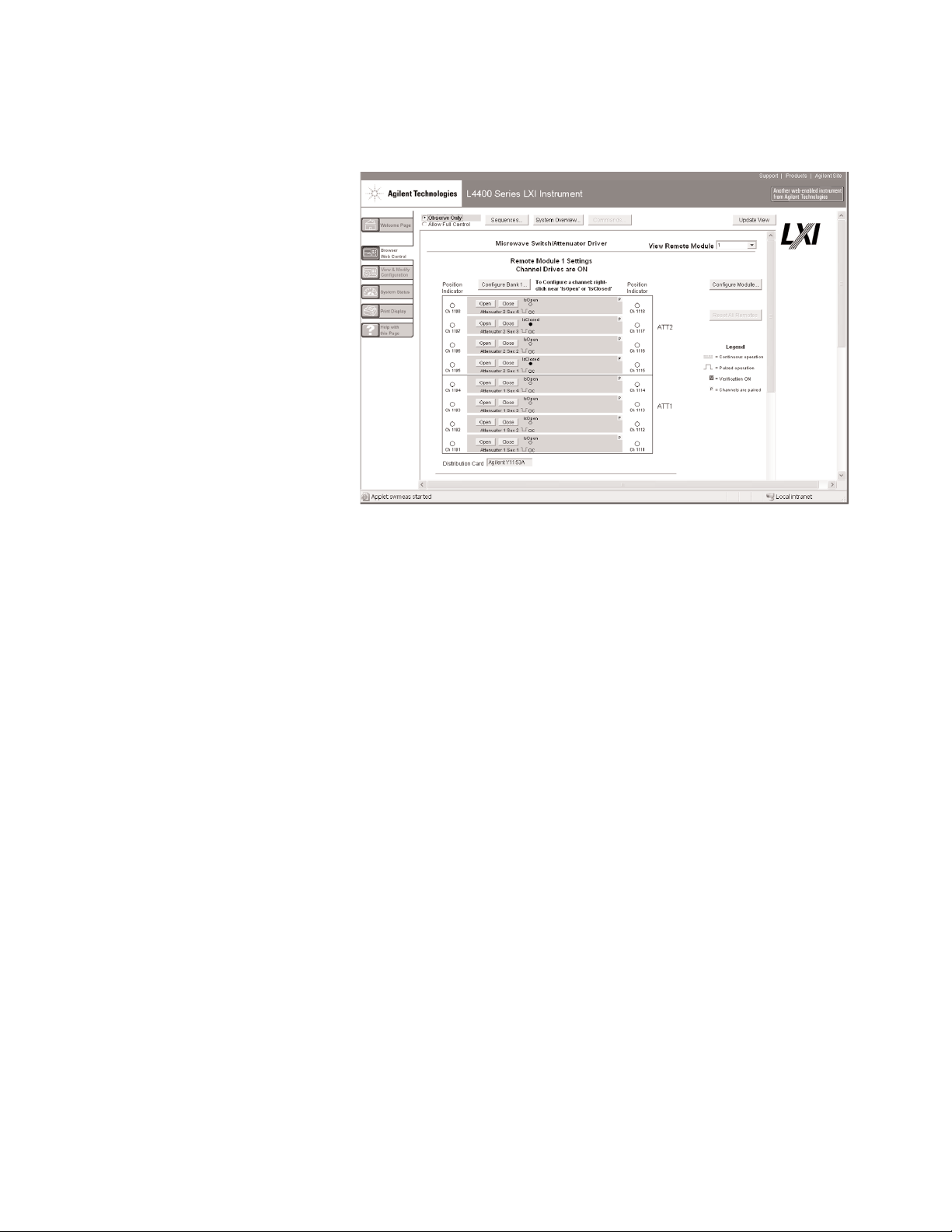
Fully-featured graphical Web
interface makes it easy to set-up
and troubleshoot your tests from
anywhere in the world
The built-in Web browser
interface provides remote
access and control of the
instrument via a Java-enabled
browser such as Internet
Explorer. Using the Web
interface, you can set up,
troubleshoot, and maintain
your instrument from remote
locations.
• View and modify
instrument setup
• Configure switch channels
and switch pairs
• Open or close switches
• Send, receive and view
SCPI commands
• Define and execute
switch sequences
• View error queue
• Get status reports on
relay cycle counts, firmware
revisions, and more
Additionally, since the Web
server is built into the instrument, you can access it on any
operating system that supports
the Web browser without
having to install any special
software. Password protection
and LAN lockout are also
provided to limit access for
additional security.
Software for most popular
programming environments
Full support for standard programming environments
ensures compatibility and efficiency. You can use direct I/O
with the software you already
have and know, or use standard
IVI and LabVIEWTMsoftware
drivers that provide compatibility with the most popular
development environments:
• Agilent T&M Toolkit for
Microsoft Visual Studio®.NET
and Agilent VEE Pro
• National Instruments
LabVIEW, LabWindows/CVI,
TestStand, and Switch
Manager
• Microsoft C/C++® and
Visual Basic®
3
Figure 1. The Web interface makes it easy to set up, troubleshoot and maintain
your test remotely
Page 4

4
High-performance switching wherever your application needs it
Power
button
Status LEDs
9-pin cable
Y1150A-Y1155A distribution
boards ordered separately
User supplied switches and cables
34945EXT
extender holds
4 distribution
boards
Page 5

5
Specifications and Characteristics
34945EXT switch drive
64 channels, low side drive mode Driver off voltage (max) 30 V
Driver off leakage current 500 uA
Driver on current (max) 600 mA
Driver on voltage (max) 0.5 V @ 600 mA
64 channels, TTL drive mode Hi output voltage 3 V @ Iout = 2 mA
Lo output voltage 0.4 V @ Iin = 20 mA
Lo input current 20 mA
34945EXT position indicator sense inputs
Channels 64
Lo input voltage (max) 0.8 V
Hi input voltage (min) 2.5 V
Input resistance >100 kΩ @ Vin ≤ 5 V
>20 kΩ @ Vin > 5 V
Maximum input voltage 30 V
34945EXT switch drive power supply (34945EXT powered by 34945A)
Voltage 24 V nominal
(external power supply
required for switches
needing different voltages)
Current 100 mA continuous +
200 mA (15 ms pulse,
25% duty cycle)
34945EXT external power connection
Voltage range 4.75 V to 30 V
Current limit 2 A
LED indicator (Current mode divers)
Channels 64
Supply voltage 5 V nominal
LED drive current 5 mA nominal
(prog 1-20 mA)
Driver compliance voltage 0.8 V
Maximum 8 34945Ext’s per L4445A
Product Specifications
Page 6

Memory
States 5 instrument states with user label in non-volatile memory
General specifications
Power supply Universal 100 V to 240 V ±10%
Power line frequency 50 Hz to 60 Hz ±10% automatically sensed
Power consumption 15 VA
Operating Environment Full accuracy for 0°C to 55°C
Full accuracy to 80% R.H. at 40 °C
Storage environment -40°C to 70°C
Dimensions (H x W x L) 40.9 x 212.3 x 379.3 mm
1.61 x 8.36 x 14.93 in
34945EXT dimensions 38.1 x 114.3 x 284.5 mm
1.5 x 4.5 x 11.2 in
with distribution boards installed
Weight 3.6 kg, 8.0 lbs
Safety conforms to CSA, UL/IEC/EN 61010-1
EMC conforms to IEC/EN 61326-1, CISPR 11
Warranty 1 year
6
Product Specifications (continued)
Page 7

Software
Agilent connectivity Agilent I/O Libraries Suite 14 or greater (E2094N)
software included
Minimum system requirements
PC hardware Intel Pentium 100 MHz, 64 Mbyte RAM, 210 Mbyte disk space
Display 800x600, 256 colors, CD-ROM drive
Operating system
1
Windows®98 SE/NT/2000/XP
Computer interfaces
Standard LAN 10BaseT/100BaseTx
Optional IEEE 488.2 GPIB
Software driver support for programming languages
Software drivers IVI-C and IVI-COM for Windows NT®/2000/XP
LabVIEW
Compatible with programming tools and environments
Agilent VEE Pro
T&M Toolkit
(reqs Visual Studio.NET)
National Instruments TestStand
Measurement Studio
LabWindows/CVI
LabVIEW
Switch Executive
Microsoft Visual Studio.NET®
C/C++
Visual Basic 6®
1
Load I/O Libraries Version M for Windows NT support or version 14.0 for Windows 98 SE support
Product Specifications (continued)
7
Page 8

Ordering information
Example configuration:
A test system is being built
that requires the following
Microwave Switching:
• (qty 2) Agilent 87206B
SP6T Switches
• (qty 8) Agilent N1810UL
SPDT Switches
Select the quantity of distribution boards for the required
switches using the ordering
info below:
• Qty 2 Y1152A
Distribution boards
to control qty 2
87206B switches.
• Qty 1 Y1150A
Distribution board
to control qty 8
N1810UL switches.
Notice that each Y1152A can
also drive two N181x switches.
Therefore if you only needed
to drive 4 N1810 switches,
then you could have controlled
those switches via the Y1152A
distribution boards already
selected.
Here is the final recommended
configuration:
• (qty 2) 87206B DC-20 GHz
SP6T Switches
• (qty 8) N1810UL DC-20 GHz
SPDT Switches
• (qty 1) L4445A
Switch/Attenuator Driver
(when ordering the L4445A,
the 34945EXT is automatically
added for controlling switches)
• (qty 2) Y1152A
Distribution Boards
• (qty1) Y1150A
Distribution Board
• Either build own cables using
off-the-shelf parts, or order
qty 1 Y1159A 16-to-16 pin
connect kit (supplies for 2
cables) and qty 2 Y1157A
9-to-10 pin cable kit
(supplies for 4 cables).
We recommend that the switch
be ordered with options for
24 V coils, position indicators,
and socket connectors. Since
24 V latching relays are specified, there is no need for an
external power supply. The
L4445A instrument can provide
power for a single 34945EXT.
Easy-to-build ribbon cables
can be built to interface each
of the switches to the Y1150A
and Y1152A distribution boards.
See the Application note:
Configuring an RF/ Microwave
Switch System (5989-2272EN)
for additional configuration
details.
8
Page 9

Ordering information (Continued)
L4445A Microwave Switch/
Attenuator driver
Includes User’s guide on CD,
test report, power cord, and
Quick Start package
Option -GPIB
Adds GPIB interface
Option 0B0
Deletes printed manual set,
full documentation included
on CD ROM
Option ABA
English printed manual set
L4445A Accessories
Distribution boards are required
for control of external switches.
One 34945EXT external driver
required for each 64 coils –
holds 4 distribution boards
per 34945EXT extender
Y1150A
34945EXT distribution board
for 8 N181x SPDT switches
Y1151A
34945EXT distribution board
for two 87104x/106x multiport
or 87406B matrix switches
Y1152A
34945EXT distribution board
for one 87204x/206x or 87606B
switch and two N181x switches
Y1153A
34945EXT distribution board
for two 84904/5/6/7/8 or
8494/5/6 step attenuators
Y1154A
34945EXT distribution board
for two 87222 transfer switches
and six N181x SPDT switches
Y1155A
34945A distribution board
w/ generic screw terminals
for driving 16 switch coils
Cable kits for connecting
switches to distribution boards:
Y1157A
9-to-10 pin cable kit for
Y1150A, Y1152A, Y1154A supplies to build 4 cables
Y1158A
10-to-10/10-to-14 pin cable kit
for Y1153A, Y1154A supplies to build 2 cables
Y1159A
16-to-16 pin cable kit for
Y1150A/51A/52A/53A/54A/55Asupplies to build 2 cables
Other accessories
Y1160A
Rack mount kit for
L4400 series instrumentsracks 2 instruments side-by-side
with sliding tray
For additional information
please visit:
http://www.agilent.com/find/L4445A
9
Page 10

www.agilent.com/find/emailupdates
Get the latest information on the
products and applications you select.
www.agilent.com/find/agilentdirect
Quickly choose and use your test
equipment solutions with confidence.
Agilent Email Updates
Agilent Technologies
www.agilent.com/find/open
Agilent Open simplifies the process
of connecting and programming
test systems to help engineers
design, validate and manufacture
electronic products. Agilent offers
open connectivity for a broad range
of system-ready instruments, open
industry software, PC-standard I/O
and global support, which are
combined to more easily integrate
test system development.
www.lxistandard.org
LXI is the LAN-based successor to
GPIB, providing faster, more efficient
connectivity. Agilent is a founding
member of the LXI consortium.
Remove all doubt
Our repair and calibration services
will get your equipment back to you,
performing like new, when promised. You will get full value out of
your Agilent equipment throughout its lifetime. Your equipment
will be serviced by Agilent-trained
technicians using the latest factory
calibration procedures, automated
repair diagnostics and genuine parts.
You will always have the utmost
confidence in your measurements.
Agilent offers a wide range of additional expert test and measurement services for your equipment,
including initial start-up assistance
onsite education and training, as
well as design, system integration,
and project management.
For more information on repair and
calibration services, go to:
www.agilent.com/find/removealldoubt
www.agilent.com
For more information on Agilent Technologies’
products, applications or services, please
contact your local Agilent office. The complete
list is available at:
www.agilent.com/find/contactus
Americas
Canada (877) 894-4414
Latin America 305 269 7500
United States (800) 829-4444
Asia Pacific
Australia 1 800 629 485
China 800 810 0189
Hong Kong 800 938 693
India 1 800 112 929
Japan 81 426 56 7832
Korea 080 769 0800
Malaysia 1 800 888 848
Singapore 1 800 375 8100
Taiwan 0800 047 866
Thailand 1 800 226 008
Europe
Austria 0820 87 44 11
Belgium 32 (0) 2 404 93 40
Denmark 45 70 13 15 15
Finland 358 (0) 10 855 2100
France 0825 010 700
Germany 01805 24 6333*
*0.14 /minute
Ireland 1890 924 204
Italy 39 02 92 60 8484
Netherlands 31 (0) 20 547 2111
Spain 34 (91) 631 3300
Sweden 0200-88 22 55
Switzerland (French) 41 (21) 8113811(Opt 2)
Switzerland (German) 0800 80 53 53 (Opt 1)
United Kingdom 44 (0) 118 9276201
Other European Countries:
www.agilent.com/find/contactus
Revised: May 7, 2007
Product specifications and descriptions
in this document subject to change
without notice.
© Agilent Technologies, Inc. 2007
Printed in USA, May 17, 2007
5989-4828EN
Related Agilent literature
Data Sheets
5988-6302EN
Agilent VEE Pro
5989-1441EN
Agilent W1140A-TKT
T&M Toolkit 2.0 with
Test Automation
5989-1439EN
Agilent E2094N
I/O Libraries Suite 14
5989-2272EN
Configuring an
RF/Microwave Switch System
Agilent Direct
Agilent
Open
 Loading...