

Page 1

Agilent 83480A Digital
Communications Analyzer
Agilent 54750A Digitizing
Oscilloscope
Quick Start Guide
Page 2

© Copyright
Agilent Technologies 2000
All Rights Reserved. Reproduction, adaptation, or translation without prior written
permission is prohibited,
except as allowed under copyright laws.
Agilent Part No. 83480-90049
Printed in USA
June 2000
Agilent Technologies
Lightwave Division
1400 Fountaingrove Parkway
Santa Rosa, CA 95403-1799,
USA
(707) 577-1400
Notice.
The information contained in
this document is subject to
change without notice. Companies, names, and data used
in examples herein are fictitious unless otherwise noted.
Agilent Technologies makes
no warranty of any kind with
regard to this material, including but not limited to, the
implied warranties of merchantability and fitness for a
particular purpose. Agilent
Technologies shall not be liable for errors contained herein
or for incidental or consequential damages in connection with the furnishing,
performance, or use of this
material.
Restricted Rights Legend.
Use, duplication, or disclosure by the U.S. Government
is subject to restrictions as set
forth in subparagraph (c) (1)
(ii) of the Rights in Technical
Data and Computer Software
clause at DFARS 252.227-7013
for DOD agencies, and subparagraphs (c) (1) and (c) (2)
of the Commercial Computer
Software Restricted Rights
clause at FAR 52.227-19 for
other agencies.
Warranty.
This Agilent Technologies
instrument product is warranted against defects in
material and workmanship for
a period of one year from date
of shipment. During the warranty period, Agilent Technologies will, at its option, either
repair or replace products
which prove to be defective.
For warranty service or repair,
this product must be returned
to a service facility designated by Agilent Technologies. Buyer shall prepay
shipping charges to Agilent
Technologies and Agilent
Technologies shall pay shipping charges to return the
product to Buyer. However,
Buyer shall pay all shipping
charges, duties, and taxes for
products returned to Agilent
Technologies from another
country.
Agilent Technologies warrants that its software and
firmware designated by Agilent Technologies for use with
an instrument will execute its
programming instructions
when properly installed on
that instrument. Agilent Technologies does not warrant that
the operation of the instrument, or software, or firmware
will be uninterrupted or errorfree.
Limitation of Warranty.
The foregoing warranty shall
not apply to defects resulting
from improper or inadequate
maintenance by Buyer, Buyersupplied software or interfacing, unauthorized modification or misuse, operation
outside of the environmental
specifications for the product,
or improper site preparation
or maintenance.
No other warranty is
expressed or implied. Agilent
Technologies specifically disclaims the implied warranties
of merchantability and fitness
for a particular purpose.
Exclusive Remedies.
The remedies provided herein
are buyer's sole and exclusive
remedies. Agilent Technolo-
gies shall not be liable for any
direct, indirect, special, incidental, or consequential damages, whether based on
contract, tort, or any other
legal theory.
Safety Symbols.
CAUTION
The
caution
sign denotes a
hazard. It calls attention to a
procedure which, if not correctly performed or adhered
to, could result in damage to
or destruction of the product.
Do not proceed beyond a caution sign until the indicated
conditions are fully understood and met.
WAR NING
The
warning
sign denotes a
hazard. It calls attention to a
procedure which, if not correctly performed or adhered
to, could result in injury or
loss of life. Do not proceed
beyond a warning sign until
the indicated conditions are
fully understood and met.
The instruction manual symbol. The product is marked with this
warning symbol when
it is necessary for the
user to refer to the
instructions in the
manual.
The laser radiation
symbol. This warning
symbol is marked on
products which have a
laser output.
The AC symbol is used
to indicate the
required nature of the
line module input
power.
The ON symbols are
|
used to mark the positions of the instrument
power line switch.
The OFF symbols
❍
are used to mark the
positions of the instrument power line
switch.
The CE mark is a registered trademark of
the European Community.
The CSA mark is a registered trademark of
the Canadian Standards Association.
The C-Tick mark is a
registered trademark
of the Australian Spectrum Management
Agency.
This text denotes the
ISM1-A
instrument is an
Industrial Scientific
and Medical Group 1
Class A product.
Typographical Conventions.
The following conventions are
used in this book:
Key type
for keys or text
located on the keyboard or
instrument.
Softkey type
for key names that
are displayed on the instrument’s screen.
Display type
for words or
characters displayed on the
computer’s screen or instrument’s display.
User type
for words or charac-
ters that you type or enter.
Emphasis
type for words or
characters that emphasize
some point or that are used as
place holders for text that you
type.
ii
Page 3

What You’ll Find in This Book
What You’ll Find in This Book
This book gives you a quick introduction to the instrument. It is not intended
as a comprehensive guide, but rather as a starting point to start using the
instrument quickly. This book is divided into three sections:
Chapter 1 provides a description of the instrument and a quick tour of
the front panel in a descriptive format, with examples that
help to illustrate the text.
Chapter 2 provides several tutorials that show how to get up and
running, how to scale a waveform vertically or horizontally,
and how to use the Help menu.
Chapter 3 provides a few simple hints in case you are experiencing
difficulty in either getting the mainframe or plug-in module
to perform properly.
To best meet your learning needs, you can use this book in one of two ways:
1
Read “A Quick Tour of the Front Panel” on page 1-4 before performing the
exercises.
2
Go straight to the exercises. This method is for users who prefer to learn how
to use the front panel by experimenting with the front-panel controls.
If you are already familiar with the information in this book, you can refer to
the
Agilent 83480A, Agilent 54750A User’s Guide
use the instrument to make many common measurements. It assumes you
have already learned how to use the front panel of the instrument, by first
reading this quick start guide.
All calibration and repair information is contained in the optional
Agilent 83480A, Agilent 54750A Service Guide
information is contained in the
mer’s Guide
.
Agilent 83480A, Agilent 54750A Program-
, which shows you how to
, while all programming
iii
Page 4

General Safety Considerations
General Safety Considerations
This product has been designed and tested in accordance with IEC Publication 61010-1, Safety Requirements for Electrical Equipment for Measurement,
Control and Laboratory Use, and has been supplied in a safe condition. The
instruction documentation contains information and warnings that must be
followed by the user to ensure safe operation and to maintain the product in a
safe condition.
WARNING
WARNING
WARNING
WARNING
WARNING
There are many points in the instrument which can, if contacted, cause
personal injury. Be extremely careful. Any adjustments or service
procedures that require operation of the instrument with protective
covers removed should be performed only by trained service
personnel.
If this instrument is not used as specified, the protection provided by
the equipment could be impaired. This instrument must be used in a
normal condition (in which all means for protection are intact) only.
To prevent electrical shock, disconnect the Agilent (Product variable)
from mains before cleaning. Use a dry cloth or one slightly dampened
with water to clean the external case parts. Do not attempt to clean
internally.
This is a Safety Class 1 product (provided with a protective earthing
ground incorporated in the power cord). The mains plug shall only be
inserted in a socket outlet provided with a protective earth contact.
Any interruption of the protective conductor inside or outside of the
product is likely to make the product dangerous. Intentional
interruption is prohibited.
No operator serviceable parts inside. Refer servicing to qualified
personnel. To prevent electrical shock, do not remove covers.
WARNING
For continued protection against fire hazard, replace line fuse only
with same type and ratings, (type T 0.315A/250V for 100/120V
operation and 0.16A/250V for 220/240V operation). The use of other
fuses or materials is prohibited. Verify that the value of the linevoltage fuse is correct.
iv
Page 5

General Safety Considerations
CAUTION
CAUTION
CAUTION
CAUTION
CAUTION
CAUTION
Before this instrument is switched on,
make sure its primary power circuitry
has been adapted to the voltage of the ac power source. Failure to set the ac
power input to the correct voltage could cause damage to the instrument when
the ac power cable is plugged in.
This product is designed for use in Installation Category II and Pollution
Degree 2 per IEC 1010 and 664 respectively.
VENTILATION REQUIREMENTS: When installing the product in a cabinet, the
convection into and out of the product must not be restricted. The ambient
temperature (outside the cabinet) must be less than the maximum operating
temperature of the product by 4°C for every 100 watts dissipated in the
cabinet. If the total power dissipated in the cabinet is greater than 800 watts,
then forced convection must be used.
Always use the three-prong ac power cord supplied with this instrument.
Failure to ensure adequate earth grounding by not using this cord may cause
instrument damage.
connect ac power until you have verified the line voltage is correct.
Do not
Damage to the equipment could result.
This instrument has autoranging line voltage input. Be sure the supply voltage
is within the specified range.
CAUTION
Electrostatic discharge (ESD) on or near input connectors can damage circuits
inside the instrument. Repair of damage due to misuse is
covered under
not
warranty. Before connecting any cable to the electrical input, momentarily
short the center and outer conductors of the cable together. Personnel should
be properly grounded, and should touch the frame of the instrument before
touching any connector.
v
Page 6

Page 7

Contents
General Safety Considerations iiv
1 Introducing the Instrument
The Agilent 83480A, Agilent 54750A—At a Glance 1-2
A Quick Tour of the Front Panel 1-4
2 Operating the Instrument
Operating the Instrument 2-2
Equipment Used in These Exercises 2-3
Exercise 1. Installing a Plug-in Module 2-4
Exercise 2. Turning On the Instrument 2-5
Exercise 3. Connecting a Signal 2-6
Exercise 4. Finding the Signal 2-7
Exercise 5. Modifying the Setup 2-8
Exercise 6. Making Measurements on the Signal 2-13
Exercise 7. Using the Help Menu 2-17
3 In Case of Difficulty
In Case of Difficulty 3-2
If the Mainframe Does Not Operate 3-3
If the Plug-in Does Not Operate 3-4
Contents-1
Page 8

Page 9

1
Entry devices 1-4
Disk drive 1-4
CAL signal 1-4
Hardkeys 1-5
Display 1-5
Softkeys 1-6
Introducing the Instrument
Page 10

Introducing the Instrument
The Agilent 83480A, Agilent 54750A—At a Glance
The Agilent 83480A, Agilent 54750A—At a
Glance
The Agilent 83480A-series digital communications analyzer or
Agilent 54750A-series digitizing oscilloscope are modular, high-performance
mainframes that contain digitizers, timebases, and display circuitry behind
vertical channel plug-in modules containing samplers, IF amplifiers, power
monitoring circuitry and O/E converter (Agilent 83485A).
The Agilent 83480A-series digital communications analyzer include these
unique capabilities:
• A full range of custom and standard telecom and datacom masks and templates with automated conformance and margin testing.
• Automated extinction-ratio and q-factor measurements.
• The ability to set the timebase display to bit period, select the appropriate
telecom bit rate, and enter the number of bits to be displayed.
If you wish to add these capabilities to an Agilent 54750A-series digitizing
oscilloscope, or use the Agilent 83485A optical plug-in module, a firmware
upgrade must first be installed. Order the Agilent 83480K communications
firmware kit and follow the installation instructions.
NOTE
The Agilent 83480A and Agilent 54750A mainframes do
designed for use with the Agilent 54710A and Agilent 54720A.
The instrument also has software modularity by having a 3-1/2 inch disk drive
and flash ROMs to allow for simple firmware upgrades of the firmware features.
The plug-in modules provide optical and electrical signal conditioning for the
A/D converters that are inside the mainframe.
1-2
accept plug-in modules
not
Page 11

Introducing the Instrument
The Agilent 83480A, Agilent 54750A—At a Glance
Certification
Agilent Technologies certifies that this product met its published specifications at the time of shipment from the factory. Agilent Technologies further
certifies that its calibration measurements are traceable to the United States
National Institute of Standards and Technology, to the extent allowed by the
Institute’s calibration facility, and to the calibration facilities of other International Standards Organization members.
1-3
Page 12

Introducing the Instrument
A Quick Tour of the Front Panel
A Quick Tour of the Front Panel
This section describes how to use the front panel. This information will help
you gain the full use of your instrument in the shortest possible time. This section divides the front panel into the following areas:
• Entry devices
• Disk drive
• CAL signal
• Hardkeys
•Display
•Softkeys
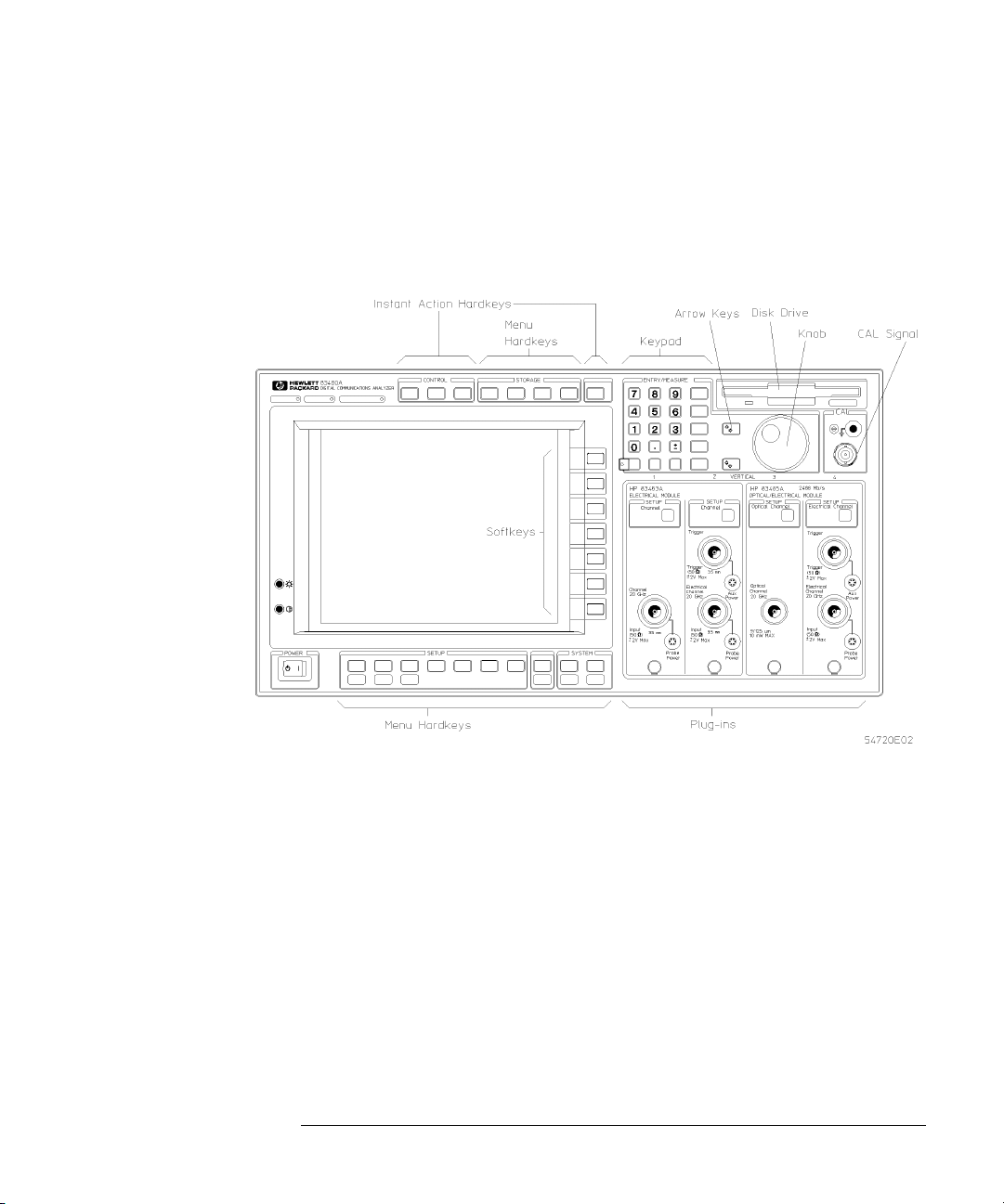
Entry devices
Disk drive
CAL signal
The entry devices include the knob, arrow keys, and keypad. The knob provides continuous control, while the arrow keys are step controls. The keypad
allows you to enter specific values.
The disk drive is a 3-1/2 inch, high-density, MS-DOS
®
compatible drive. You
can use the disk drive for loading applications, storing and loading waveforms,
storing and loading instrument setups, printing waveforms to a file, or loading
new system firmware.
MS-DOS
is a registered trademark of Microsoft Corporation.
The CAL signal is a dc voltage level used during the calibration routines. It is
internally generated and only activated during calibration routines. It can be
controlled by the user by pressing:
Utility
Calibrate
,
1-4
Page 13
Introducing the Instrument
A Quick Tour of the Front Panel
Hardkeys
The two types of hardkeys are instant action and menu.
Clear display
and
Run
are examples of instant action keys because as soon as you press them, the
instrument changes operating states.
Time base
and
Trigger
are examples of
menu keys. Pressing them causes softkey menus to come up on the right side
of the display.
Display
Figure 1-1. The front panel of the instrument
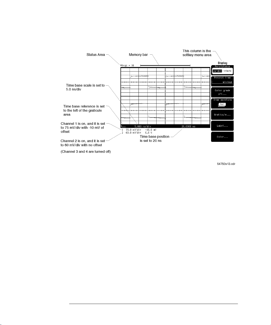
Figure 1-2 shows the main areas of the display, and how you can interpret
some of the instrument’s settings from the display.
1-5
Page 14
Introducing the Instrument
A Quick Tour of the Front Panel
Softkeys
Figure 1-2. The instrument display
The softkeys are to the right of the display, and instead of placing a label on
the softkey itself, the label is actually located on the display next to the softkey. These labels on the display are called menus, and the menu being displayed depends on which key has been pressed. For example, pressing
base
brings up the Time Base menu, while pressing
Trigger
brings up the Trigger
Time
menu.
There are five types of softkeys, and there are some differences on how each
type of softkey operates. The five types of softkeys are toggle, menu, continuous, list, and single choice. Because the Trigger menu contains all five types of
softkeys, it is used over the next few pages to demonstrate the differences
among the softkeys.
When you press the
Trigger
key, the Trigger softkey menu comes up on the
right side of the display as shown in Figure 1-3.
Toggle softkeys
A typical example of the toggle softkeys is
Sweep
. A toggle softkey allows you
to choose between two or more selections, and you change selections by
pressing that same softkey.
1-6
Sweep
has choices of either triggered or freerun.
Page 15

Introducing the Instrument
A Quick Tour of the Front Panel
The highlighted choice is the selection that is currently active. In Figure 1-3,
triggered is highlighted, which indicates that the instrument is set to triggered
sweep.
Figure 1-3. Toggle softkey selection
Menu softkeys
A typical example of the menu softkeys is
External Scale...
(refer to Figure 1-3
on page 1-7). The ellipses after the word "scale" indicate that when you press
this softkey, a new softkey menu comes up on the display that allows you to
make several additional choices (refer to Figure 1-4). To exit this menu, simply press the
Done
softkey. The display returns to the previous menu.
1-7
Page 16

Introducing the Instrument
A Quick Tour of the Front Panel
Figure 1-4. Menu softkey selection
Continuous softkeys
A typical example of the continuous softkeys is
Level
. It has a range of values
that can be changed with the keypad, arrow keys, or knob.
Figure 1-5. Continuous softkey selection
1-8
Page 17

Introducing the Instrument
A Quick Tour of the Front Panel
Because the Trigger menu only has one of this type of softkey, it is active when
the menu comes up on the display. You do not need to press the
Level
softkey
when you want to change the trigger level. However, the Time base menu has
at least two of this type of softkey,
and Position
. In this case, only one of the softkeys is active at a time. To make
Bit Rate
(
Agilent 83480A only
) and
Scale
the other softkey active, you must press the corresponding softkey. You can
tell which softkey is currently active because it has a different colored background from the rest of the softkeys.
When using time base scale or channel scale, the knob and arrow keys operate
in two modes. One mode is a 1-2-5 sequence, while the other mode is a fine
mode that allows you to make smaller incremental changes. You activate the
fine mode by pressing
with the word
Fine
active, you will see the word
You get out of the Fine mode by simply pressing
by pressing the arrow key with the word
Shift
on the keypad, followed by pressing the arrow key
written in blue above that key. When the fine mode is
Fine
at the top-right corner of the graticule area.
Shift
on the keypad, followed
Fine
written above it.
List softkeys
A typical example of the list softkeys is
Hysteresis
. It has several stacked rectangles that represents a list of choices you can choose from. The top rectangle
shows the selection that is currently active. In the example below, normal is
the current selection.
Figure 1-6. List softkey selection
1-9
Page 18

Introducing the Instrument
A Quick Tour of the Front Panel
You change selections by pressing the
Hysteresis
softkey, which brings up a second level softkey menu on the display. Then, you use the softkeys, arrow keys,
or knob to change selections. To activate that selection, press the
then the display returns to the previous softkey menu. If you press the
Enter
softkey,
Cancel
softkey, the instrument returns to the previous selection.
Single choice softkeys
A typical example of the single choice softkeys is
Enter
. There are several variations of this type of softkey throughout the many softkey menus. When you
press the softkey, the instrument executes that softkey command.
Figure 1-7. Single choice softkey selection
1-10
Page 19

2
Equipment Used in These Exercises 2-3
Exercise 1. Installing a Plug-in Module 2-4
Exercise 2. Turning On the Instrument 2-5
Exercise 3. Connecting a Signal 2-6
Exercise 4. Finding the Signal 2-7
Exercise 5. Modifying the Setup 2-8
Exercise 6. Making Measurements on the Signal 2-13
Exercise 7. Using the Help Menu 2-17
Operating the Instrument
Page 20

Operating the Instrument
Operating the Instrument
Operating the Instrument
This chapter contains several exercises that will familiarize you with the operation of the instrument.
Exercises 1–3 show how to get the instrument up and running.
Exercises 4 and 5 demonstrate the vertical, horizontal, and trigger menus by
having you display a signal and then use the channel and
time base menus to expand the signal.
Exercise 6 shows you how to use the markers and automatic
measurement features to make a pulse width and voltage
amplitude measurement.
Exercise 7 introduces you to the Help menu.
You will find it easier to perform these exercises if you are at least a little
familiar with how to use the front panel. The best way to learn how to use the
front panel is to read Chapter 1, “Introducing the Instrument”.
Note
Clean the cabinet using a damp cloth only.
2-2
Page 21

Operating the Instrument
Equipment Used in These Exercises
Equipment Used in These Exercises
All of the pictures of the display in this book were generated using an
Agilent 83480A with an Agilent 83483A, 54751A electrical plug-in module, and
the signal from the Agilent 8133A pulse generator. If you are using a different
plug-in module or signal source, your display and instrument settings may
vary from the pictures in this book.
With the Agilent 83480A, the Agilent 83485A optical/electrical plug-in module
could also have been used. In this case, we would connect the signal to the
electrical input of the Agilent 83485A.
2-3
Page 22

Operating the Instrument
Exercise 1. Installing a Plug-in Module
Exercise 1. Installing a Plug-in Module
The purpose of a plug-in module is to provide measurement channels, including sampling for the mainframe. A plug-in module scales the input signal, sets
the bandwidth of the system, and allows the offset to be adjusted so the signal
can be viewed. The output of the plug-in module is an analog signal that is
applied to the A/D converters inside the mainframe.
1
Slide the plug-in module into either slots 1 and 2 or slots 3 and 4.
Note
The plug-in module will
If the mainframe is already turned on, you do not need to turn it off before you
install or remove a plug-in module. After a plug-in module is installed, the
mainframe identifies the plug-in module and the slot in which it is installed.
Note
In the examples to follow, it is assumed the Agilent 83483A or Agilent 54751A plug-in
module is resident in slots 1 and 2 of the mainframe.
2
Finger-tighten the knurled screw at the bottom of the plug-in module.
The RF connectors on the rear panel of the plug-in module are spring-loaded.
Finger-tighten the knurled screw to ensure there is a good ground connection
between the plug-in module and the mainframe.
3
To remove the module loosen the knurled screws and then pull on the screws
to take out the module. Do
operate if plugged into slots 2 and 3.
not
pull on the cables or connectors.
not
2-4
Page 23

Operating the Instrument
Exercise 2. Turning On the Instrument
Exercise 2. Turning On the Instrument
1
Set the line-voltage switch on the rear panel to the correct voltage selection for
your power source.
2
Connect a power cord from a power source to the rear-panel connector of the
mainframe.
3
Set the rear-panel line switch to the ON position.
CAUTION
When the mainframe is set to the 115 VAC mode, use the supplied power cord.
If you use an alternate power cord that
of the instrument, the power cord may become warm or the instrument may
not operate.
4
Set the front-panel power switch to ON.
After a few seconds, you will see a graticule on the display and a softkey menu
on the right side of the display. If the display is blank or if the message,
Power-On Test Failed
Chapter 3, “In Case of Difficulty” or to the optional
Service Guide
.
, appears at the top of the display, refer to
cannot
handle the power requirements
Agilent 83480A, 54750A
2-5
Page 24

Operating the Instrument
Exercise 3. Connecting a Signal
Exercise 3. Connecting a Signal
CAUTION
CAUTION
Electrostatic discharge (ESD) on or near input connectors can damage circuits
inside the instrument. Repair of damage due to misuse is
warranty. Before connecting any cable to the electrical input, momentarily
short the center and outer conductors of the cable together. Personnel should
be properly grounded, and should touch the frame of the instrument before
touching any connector. For more information regarding ESD, refer to the
Agilent 83480A, 54750A User’s Guide
1
Using the Agilent 8133A pulse generator (or equivalent), set a trigger and
square wave signal to the following:
Trigger level . . . . . . . . . . . . . . . . . . . . . . . . . . . 200 mV (do not exceed 2 Vp-p)
Pulse level . . . . . . . . . . . . . . . . . . . . . . . . . . . . . 500 mV (do not exceed 2 Vp-p)
Pulse frequency . . . . . . . . . . . . . . . . . . . . . . . . . . . . . . . . . . . . . . . . . . . . 50 MHz
Cables can build up high voltage levels that can discharge into the channel or
trigger inputs and cause damage. Cables should be discharged using a short or
a 50Ω terminator prior to connection.
2
Make sure the trigger and pulse signals are enabled.
3
Connect the trigger to the trigger input (channel 2) on the Agilent 83483A,
54751A electrical plug-in module.
4
Connect the pulse signal to the electrical input (channel 1) on the
Agilent 83483A, 54751A electrical plug-in module.
.
covered under
not
5
Display the Setup menu (on the Agilent 83480A, 54750A) and select the
default setup by pressing:
Setup
Default setup
,
The default setup puts the instrument in a predefined operating condition. This
gives you a known starting point for the following exercises. The default conditions are listed in the setup section of the
.
Guide
2-6
Agilent 83480A, 54750A User’s
Page 25

Operating the Instrument
Exercise 4. Finding the Signal
Exercise 4. Finding the Signal
The purpose of this exercise is to demonstrate the Autoscale function. The
Autoscale function can be used to automatically set up the display for most
input signals.
To activate the Autoscale function, press
Figure 2-1 will be displayed.
When the Autoscale function is enabled, the instrument quickly analyzes the
signal and sets up the vertical, horizontal, and trigger to optimize the display
of the signal. Autoscale can find repetitive signals with:
• a frequency greater than or equal to 50 Hz
• a duty cycle greater than 1%
• an amplitude greater than 50 mV p-p
Autoscale
. A screen similar to
Figure 2-1. Signal displayed using the Autoscale function
If you unintentionally press the
function, press
existed just prior to pressing the
Shift, Undo Autoscale
Autoscale
Autoscale
key or wish to disable the Autoscale
. The instrument is reset to the settings that
key.
2-7
Page 26

Operating the Instrument
Exercise 5. Modifying the Setup
Exercise 5. Modifying the Setup
The purpose of this exercise is to show you the Channel and Time Base
menus.
Changing the vertical scale
1
To display the Channel menu and change the vertical scaling, press:
Channel
(located on the plug-in module),
Change the scaling so the vertical height of the signal is about eight divisions,
using the knob, arrow keys or keypad.
Scale
Selecting Fine mode
When the knob and arrow keys are
ing in a 1-2-5 sequence. You can change the scaling in 1 mV increments by
using the keypad, or by setting the knob and arrow keys to the Fine mode.
2
To set the instrument to the Fine mode, press:
Shift, Fine
The word
fine mode is activated.
FINE
appears at the top-right corner of the display area when the
in the Fine mode, they change the scal-
not
2-8
Page 27

Operating the Instrument
Exercise 5. Modifying the Setup
Using the keypad
When using the Agilent 83483A, 54751A electrical plug-in module, the knob or
arrow key changes the scaling from 50 mV/div to 100 mV/div, in one step. At
50 mV/div the signal is clipped, and at 100 mV/div the signal is
to take advantage of the full vertical size of the display. In this case, you can
use the keypad to set the scaling to 75 mV/div.
3
To set the scaling to 75 mV with the keypad, type the number 75 on the keypad.
Then press
milli
, for millivolts, to select the unit of measure.
expanded
not
When you select a key with a unit of measure written on it, you do
press the
that do
ing on the value you enter with the keypad, the instrument may round the
value up or down. For example, if you try to enter 75.75 mV/div, the instrument will automatically round the entry to 75.8 mV/div.
Enter
key. You only press the Enter key if you are entering numbers
require a unit of measure or that are in volts or seconds. Depend-
not
need to
not
Setting the offset
Offset is similar to the vertical position on analog instruments, except offset is
calibrated. If offset is set to –10 mV, then you know the vertical center of the
display is –10 mV. (For optical channels, offset is referenced two divisions
above the bottom of the display.)
4
To move the waveform vertically on the display, press:
Offset
Readjust the scaling and offset until the signal is expanded vertically and is centered on the display as shown in Figure 2-2.
2-9
Page 28

Operating the Instrument
Exercise 5. Modifying the Setup
Figure 2-2. Signal vertical display
Note — Agilent 83480A only
You can automatically adjust the vertical scale, instead of following the preceding procedure by pressing:
Channel,
Channel autoscale
The amplitude scale is optimized for the input signal while the timebase settings are left
alone.
Changing the time base
5
To display the Time Base menu and change the horizontal scale, press:
Time base
Use the knob, arrow keys or keypad to change the scaling so the horizontal
width of the positive portion of the signal is about eight divisions.
2-10
Scale
,
Page 29

Operating the Instrument
Exercise 5. Modifying the Setup
Using the keypad
6
When the knob and arrow keys are not in the Fine mode, they operate in a 1-2-5
sequence, changing the scale from 5 ns/div to 2 ns/div in one large step. You can
use Fine mode so the knob and arrow keys adjust in smaller increments, or you
can use the keypad to enter a smaller value, like 1.4 ns/div.
Using the Position function
7
To horizontally center the signal on the display, press:
Position
The Position function moves the waveform horizontally on the display. (Position is sometimes referred to as delay.) The reference point is indicated by an
arrow at the bottom of the display as shown in Figure 2-3.
Figure 2-3. Signal horizontal display
2-11
Page 30

Operating the Instrument
Exercise 5. Modifying the Setup
Setting the reference
8
To set the reference to the left or center of the graticule area, press:
Reference
2-12
Page 31

Operating the Instrument
Exercise 6. Making Measurements on the Signal
Exercise 6. Making Measurements on the Signal
The purpose of this exercise is to familiarize you with the Marker menu and
the automatic measurement features of the instrument. You will begin by
using the manual markers to make a pulse width and an amplitude measurement on channel 1. After that, you will make the same measurements using
the automatic measurement features. There are many additional features built
into the instrument. Refer to the
more information on making automatic measurements.
Selecting the manual marker mode
1
To select the manual marker mode, press:
Agilent 83480A, 54750A User’s Guide
for
Marker
Change the mode selection by using the knob, arrow keys, or softkeys.
mode, manual, Enter
,
Setting the X, Y source
In the manual marker mode, there are two X-markers and two Y-markers. You
can position the X-markers horizontally and the Y-markers vertically on the
display. Use the X-markers to make timing measurements and the Y-markers
to make amplitude measurements.
2
To set the X1, Y1 Source to channel 1, press:
X1, Y1 Source, channel 1, Enter
3
To set the X2, Y2 Source to channel 1, press:
X2, Y2 Source, channel 1, Enter
2-13
Page 32

Operating the Instrument
Exercise 6. Making Measurements on the Signal
Positioning the markers
4
To position the X1 marker, press:
X1 Position
Set the X1 marker to the left edge of the pulse.
5
To position the X2 marker, press:
X2 Position
Set the X2 marker to the right edge of the pulse.
6
To position the Y1 marker, press:
Y1 Position
Set the Y1 marker to the bottom of the pulse.
7
To position the Y2 marker, press:
Y2 Position
Set the Y2 marker to the top of the pulse.
The display will be similar to Figure 2-4.
Figure 2-4. Signal custom measurements
2-14
Page 33

Operating the Instrument
Exercise 6. Making Measurements on the Signal
Notice the ∆X and ∆Y at the bottom of the display. The ∆X value is the width
measurement, and the ∆Y value is the amplitude measurement. The markers
allow you to make custom measurements on signals. Remember, they are
tied directly to the waveform data stored in memory, they are just positions on
the display.
Making an automatic +width measurement
8
To make an automatic +width measurement on channel 1, press:
not
Shift, +width
The automatic measurement results are displayed at the bottom left of the
screen.
channel 1, Enter
,
Making an automatic amplitude measurement
9
To make an automatic amplitude measurement on channel 1, press:
Shift, V amptd
The IEEE pulse parameter standards are used for all of the automatic measurements, unless changes are made in the define measurement menu.
Automatic measurements are preferred because they are faster and more
repeatable than manual marker measurements. Automatic measurements use
the waveform data stored in memory for all calculations, and the waveform
data in memory has a higher resolution than the resolution of the display. The
manual markers are
positions on the display.
The automatic measurement results are placed on the display where the vertical scale and offset values are normally displayed as shown in Figure 2-5.
channel 1
,
Enter
,
tied to the waveform data in memory, they are just
not
2-15
Page 34

Operating the Instrument
Exercise 6. Making Measurements on the Signal
Figure 2-5. Signal automatic measurements
Displaying the scale and offset values
10
To redisplay the vertical scale and offset values, press:
Shift, Clr meas
The automatic measurement results are replaced by the vertical scale and offset values.
2-16
Page 35

Exercise 7. Using the Help Menu
Exercise 7. Using the Help Menu
Operating the Instrument
To display the Help menu, press
played.
Figure 2-6. The instrument Help menu
A three-column index appears on the display. The left column lists the features of the instrument, the middle column lists the front-panel key, and (if
needed) the right column lists the softkey you press to find that feature. You
can use either the knob or arrow keys to scroll through the Help menu.
Help
. A screen similar to Figure 2-6 is dis-
2-17
Page 36

Page 37

3
If the Mainframe Does Not Operate 3-3
If the Plug-in Does Not Operate 3-4
In Case of Difficulty
Page 38

In Case of Difficulty
In Case of Difficulty
In Case of Difficulty
This chapter provides suggestions for you to follow if the mainframe or plug-in
module fails to operate. For a complete listing of display messages, refer to the
Agilent 83480A, 54750A User’s Guide
.
CAUTION
For complete service information, refer to the optional
54750A Service Guide
Review the procedure being performed when the problem occurred. A few
minutes spent performing some simple checks, before calling Agilent Technologies or returning the unit for service, may save waiting for your instrument to
be repaired.
Electrostatic discharge (ESD) on or near input connectors can damage circuits
inside the instrument. Repair of damage due to misuse is
warranty. Before connecting any cable to the electrical input, momentarily
short the center and outer conductors of the cable together. Personnel should
be properly grounded, and should touch the frame of the instrument before
touching any connector. Refer to the
for further information regarding ESD.
.
Agilent 83480A, 54750A User’s Guide
Agilent 83480A,
covered under
not
3-2
Page 39

If the Mainframe Does Not Operate
If the Mainframe Does Not Operate
If the mainframe does not operate, check the following:
1
Is the line fuse good?
2
Does the line socket have power?
3
Is the unit plugged in to the proper ac power source?
4
Is the mainframe turned on?
5
Is the rear-panel line switch set to on?
6
Will the mainframe power up
If the mainframe still does not power up, refer to the optional
Agilent 83480A, 54750A Service Guide
fied service department. Refer to the
for a complete listing of Agilent Sales and Service Offices.
without
the plug-in module installed?
or return the mainframe to a quali-
Agilent 83480A, 54750A User’s Guide
In Case of Difficulty
3-3
Page 40

In Case of Difficulty
If the Plug-in Does Not Operate
If the Plug-in Does Not Operate
If the plug-in does not operate:
1
Make the following checks:
• Is the plug-in module firmly seated in the mainframe slot?
• Are the knurled screws at the bottom of the plug-in module finger-tight?
• If other equipment, cables, and connectors are being used with the plug-in
module, are they connected properly and operating correctly?
• Review the procedure for the test being performed when the problem ap-
peared. Are all the settings correct? Can the problem be reproduced?
• Are the connectors clean? Refer to the
for more information about cleaning the connectors.
Guide
• Does the plug-in module work in the other two slots (1,2 or 3,4)?
2
Perform the following procedures:
• Make sure the instrument is ready to acquire data by pressing
• Verify the pulse output is connected to channel 1 on the Agilent 83483A,
54751A electrical plug-in module.
• Verify the trigger output is connected to the trigger input.
• Find any signals on the channel inputs by pressing
• Verify the Agilent 8133A pulse generator is set to:
Waveform . . . . . . . . . . . . . . . . . . . . . . . . . . . . . . . . . . . . . . . . . . . square wave
Amplitude. . . . . . . . . . . . . . . . . . . . . . . . . . . . . . . . . . . . . . . . . . . . . . . 500 mV
Frequency. . . . . . . . . . . . . . . . . . . . . . . . . . . . . . . . . . . . . . . . . . . . . . . 50 MHz
Trigger . . . . . . . . . . . . . . . . . . . . . . . . . . . . . . . . . . . . . . . . . . . . . . . . . 200 mV
Pulse/trigger . . . . . . . . . . . . . . . . . . . . . . . . . . . . . . . . . . . . . . . . . . . . . enabled
• See if any signals are present at the channel inputs by pressing:
Trigger
Sweep, freerun
,
Agilent 83480A, 54750A User’s
Run
.
Autoscale
.
3-4
Page 41

In Case of Difficulty
If the Plug-in Does Not Operate
After viewing the signal, press
triggered
.
• Make sure Channel Display is on by pressing:
Channel
Display on off
,
• Make sure the channel offset is adjusted so the waveform is not clipped off
the display.
• If you are using the plug-in module only as a trigger source, make sure at
least one other channel is turned on.
If all of the channels are turned off, the mainframe will
not
trigger.
• Make sure the mainframe identifies the plug-in module by pressing:
Utility
System config...
,
The calibration status of the plug-in modules is listed near the bottom of the
display, in the box labeled "
Plug-ins
". If the model number of the plug-in
module is listed next to the appropriate slot number, then the mainframe
has identified the plug-in.
~known"
If "
is displayed, instead of the model number of the plug-in
module, remove and reinsert the plug-in module in the same slot. If
~known
"
" is still displayed, then the memory contents of the plug-in module
are corrupt. Refer to the service guide for the plug-in module or contact a
qualified service department. If all of the above steps check out okay, and
the plug-in module still does not operate properly, then the problem is
beyond the scope of this book. Refer to the plug-in module service guide or
return the plug-in to a qualified service department.
3-5
Page 42

Page 43

Index
Symbols
+width key, 2-15
A
amplitude, 2-7
measurement, 2-14
scale, 2-10
analog signal, 2-4
automatic measurement, 2-13, 2-15
Autoscale key, 2-7, 3-4
B
bandwidth, 2-4
Bit Rate softkey, 1-8
C
cabinet, cleaning, iiv
CAL Signal overview, 1-4
Calibrate softkey, 1-4
Cancel softkey, 1-9
care
of cabinet, iiv
Channel autoscale softkey, 2-10
Channel key, 2-8, 3-5
channel scale, 1-9
classification
product, iiv
cleaning
cabinet, iiv
Clear display key, 1-5
Clr meas key, 2-16
connecting a signal, 2-6
continuous softkeys, 1-8
custom measurement, 2-14
D
Default setup softkey, 2-6
description of the instrument, 1-1
disk drive overview, 1-4
display
messages, 3-2
overview, 1-5
Display softkey, 3-5
Done softkey, 1-7
duty cycle, 2-7
E
electrical plug-in module, 2-3, 2-8
Enter softkey, 1-9–1-10, 2-13
entry device overview, 1-4
equipment used for display, 2-3
expanding the signal, 2-8
External Scale softkey, 1-7
F
finding input signals, 2-7
Fine softkey, 1-9, 2-8
freerun softkey, 3-4
front panel, 1-4, 1-10
fuse
values, iiv
H
hardkey overview, 1-5
Help key, 2-17
help menu, 2-17
horizontal
display, 2-7
scale, 2-10
Hysteresis softkey, 1-9
I
IEC Publication 61010-1, iiv
input signal, 2-4, 2-7
installing a plug-in module, 2-4
instant action key, 1-5
instrument
description, 1-1
settings, 1-5
L
Level softkey, 1-8
line voltage switch, 2-5
list softkeys, 1-9
Index-1
Page 44

Index
M
manual marker measurements, 2-15
manual softkey, 2-13
Marker key, 2-13
measuring the signal, 2-13
menu
display, 1-6
key, 1-5
softkeys, 1-7
messages on display, 3-2
milli key, 2-9
mode softkey, 2-13
modifying the setup, 2-8
O
offset, 2-16
adjustment, 2-4
Offset softkey, 2-9
optical/electrical plug-in module, 2-3
P
plug-in module, 2-8
installing, 2-4
Position softkey, 1-8, 2-11
power cord, 2-5
pulse
frequency, 2-6
generator, 2-3, 2-6
level, 2-6
setup modification, 2-8
Shift key, 1-9
signal
connection, 2-6
markers, 2-8
measurement, 2-13
single choice softkeys, 1-10
softkey overview, 1-6
square wave signal, 2-6
Sweep softkey, 1-6, 3-4
System configuration softkey, 3-5
T
Time base key, 1-5
time base scale, 1-9
toggle softkeys, 1-6
trigger
display, 2-7
level, 2-6
signal, 2-6
Trigger key, 1-5–1-6, 3-4
triggered softkey, 3-4
troubleshooting, 3-2–3-5
turning on the instrument, 2-5
U
Undo Autoscale key, 2-7
unit of measure, 2-9
using the front panel, 1-4, 1-10
Utility key, 1-4, 3-5
R
rear panel
connector, 2-5
line switch, 2-5
Reference softkey, 2-12
repetitive signals, 2-7
Run key, 1-5, 3-4
S
safety, iiv
laser classification, iiv
scale increments, 2-8
Scale softkey, 1-8, 2-8, 2-10
Setup key, 2-6
Index-2
V
V amptd key, 2-15
vertical
display, 2-7, 2-9
scale, 2-16
voltage selection, 2-5
W
width measurement, 2-14
X
X1, Y1 Source softkey, 2-13
Page 45

X1/X2 Position softkeys, 2-14
X2, Y2 Source softkey, 2-13
Y
Y1/Y2 Position softkeys, 2-14
Index
Index-3
Page 46

 Loading...