

Page 1
User
and
Service Guide
Agilent
83446A/B
Lightwave Clock/Data
Receiver
Page 2
Agilent
Edition
1400
Santa
part
1
Printed
F
ountaingrove
Rosa,
95403-1799,
Notice
.
The
without
with
warranties
T
echnologies
notice
regard
of
consequential
of
this
material.
number:
83446-90018
in
US
A
P
arkway
CA
US
A
information
.
to
Agilent
this
T
material,
merchantability
shall
not
be
damages
in
March
2000
,
contained
echnologies
including
and
tness
liable
for
connection
in
this
makes
but
errors
with
document
no
warranty
not
limited
for
a
particular
contained
the
furnishing,
is
subject
to
, the
herein
to
change
of
any
kind
implied
purpose
or
.
for
incidental
performance
Agilent
,
or
or
use
Restricted
Government
of
the
252.227-7013
Commercial
other agencies
c
Copyright Agilent T
Rights
Rights
is
subject
in
T
echnical Data
for
DOD
Computer
.
Legend.
Use
to
restrictions
agencies
Software
echnologies 2000
,
duplication, or
as set
and Computer
,
and
subparagraphs
Restricted
disclosure by
forth in
Software
Rights
subparagraph
clause
(c) (1)
and
clause
at
FAR
the
U
(c)
at
DF
(c)
(2)
52.227-19
.S
ARS
.
(1)
(ii)
of
the
for
All Rights Reserved. Reproduction, adaptation, or translation without prior
written permission is prohibited, except as allowed under the copyright laws
.
Page 3
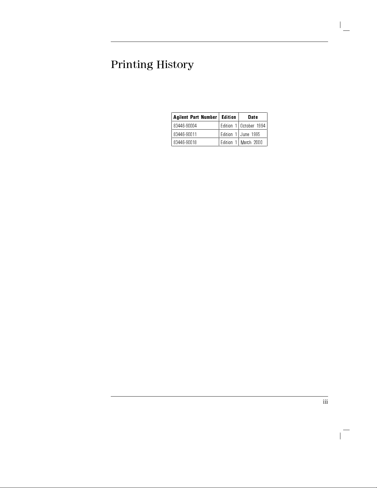
Printing
History
Agilent
Part
Number
83446-90004 Edition1October
83446-90011 Edition1June
83446-90018 Edition1March
Edition Date
1994
1995
2000
iii
Page 4
C
W
AU
A
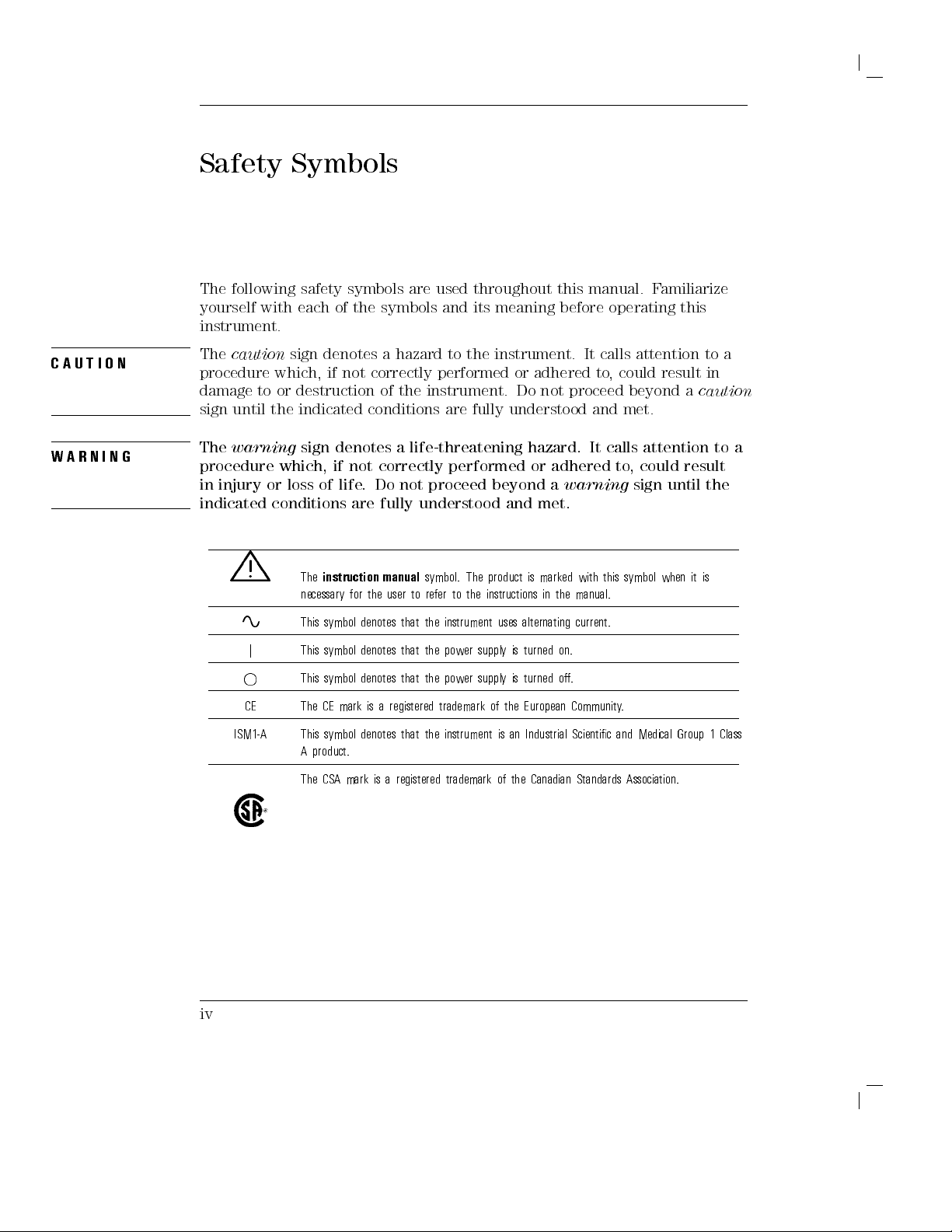
Safety
The
following safety
yourself
Symbols
with each
symbols
of
the
are
symbols
used
and
throughout
its
meaning
this
before
manual.
operating
F
amiliarize
this
instrument.
The
TI
O
N
caution
procedure
damage
sign
until
The
R
N
I
N
G
warning
procedure
in
injury
indicated
sign
which, if
to
or
destruction
the
indicated
sign
which, if
or
loss
conditions
denotes a
not correctly
conditions
denotes
not
of
life
.
are
hazard
performed
of
the
instrument.
a
life-threatening
correctly
Do
not
proceed
fully
understood
to
the
instrument.
are
fully
performed
beyond
or
adhered
Do
not
understood
hazard.
or
adhered
a
warning
and
met.
It
calls
to
,
proceed
and
It
calls
attention
could
result
beyond
met.
attention to
to
,
could
sign
to
in
a
caution
result
until the
a
a
iv
L
A
j
CE
ISM1-A
The
instruction
necessary
This
symbol
This
symbol
This
symbol
The
CE
This
symbol
A
product.
The
CSA
for
mark
mark
manual
the
denotes
denotes
denotes
is
a
denotes
is
user
to
that
that
that
registered
that
a
registered
symbol.
refer
the
instrument
the
power
the
power
trademark
the
instrument
trademark
to
The
the
supply
supply
product
instructions
uses
alternating
is
turned
is
turned
of
the
European
is
an
of the
is
marked
with
in
the
manual.
current.
on.
o.
Community
Industrial
Scientic
Canadian Standards
this
.
and
symbol
when
Medical Group
Association.
it
is
1 Class
Page 5
General
This
is
W
A
R
N
I
N
G
ground
inserted
Any
a
incorporated
in
interruption
instrument
interruption
Safety Considerations
Safety
Class
a
socket
is
likely
is
prohibited.
of
I
product
in
the
outlet
the
to
make
(provided
power
provided
protective
the
instrument
cord).
with
conductor
with
a
The
mains
a
protective
inside
dangerous
protective
plug
shall
earth
or
outside
.
Intentional
earthing
only
contact.
of
the
be
W
A
R
N
I
N
G
Before
grounded
socket
of
or disconnection
this
outlet
the
protective
instrument
through the
provided
(grounding)
of the
is
switched
protective
with
protective
on
conductor
conductor
protective earth
,
make
earth
,
inside or
terminal
sure
of
the
contact.
it
has
been
ac
power
Any
outside the
can
result
properly
cable
to
a
interruption
instrument,
in
personal
injury.
If
this
W
A
R
N
I
N
G
equipment
condition
W
A
R
NI
N
G
There
personal
procedures
covers
W
A
R
N
I
N
G
W
A
RN
IN
G
C
A
U
T
I
O
N
No
personnel.
F
same
Always
Failure to ensure adequate earth grounding by not using
instrument
could
(in
are
many
injury
that
removed
operator
T
or
continued protection
type
and ratings
use
the
instrument damage
is
not
be
impaired.
which
all
points in
.
Be extremely
require
should
serviceable
o
prevent
three-prong A
.
used
as
This
means
for
the
instrument
careful.
operation of
be performed
parts
inside
electrical
against re
. The
use of
C
power
specied,
instrument
protection
Any
the instrument
only by
.
Refer
shock,
do
hazard, replace
other fuses
cord
the
protection
must
are
intact)
which
can,
adjustments
trained
servicing
not
remove
or
supplied
provided
be
used
only
.
if
contacted,
or
service
with
protective
service
to
qualied
covers
line fuse
materials
with
is
this
instrument.
this cord may cause
by
the
in
a
normal
cause
personnel.
.
only
with
prohibited.
CAUTION
This product has autoranging
within the specied range
.
line voltage input. Be sure the supply voltage is
v
Page 6
Certication
and Assistance
Agilent
at
certies
National
by
Technologies
the time
that its
Institute of
the Institute's
International
Product
are
F
or
Service
maintenance
available
any
assistance
Oce
of
shipment
certies
from
that
the
calibration measurements
Standards and
calibration facility
Standards
Organization
agreements
for
A
gilent
T
echnologies
,
contact
your
.
this
factory
T
echnology
,
and
members
and
nearest
product
.
Agilent
are
to
the
other
customer
products.
A
gilent
met
its
T
echnologies
traceable
(NIST),
calibration
.
T
echnologies
published
to
the
to
the
extent
facilities
assistance
Sales
specications
further
United
States
allowed
of
other
agreements
and
vi
Page 7
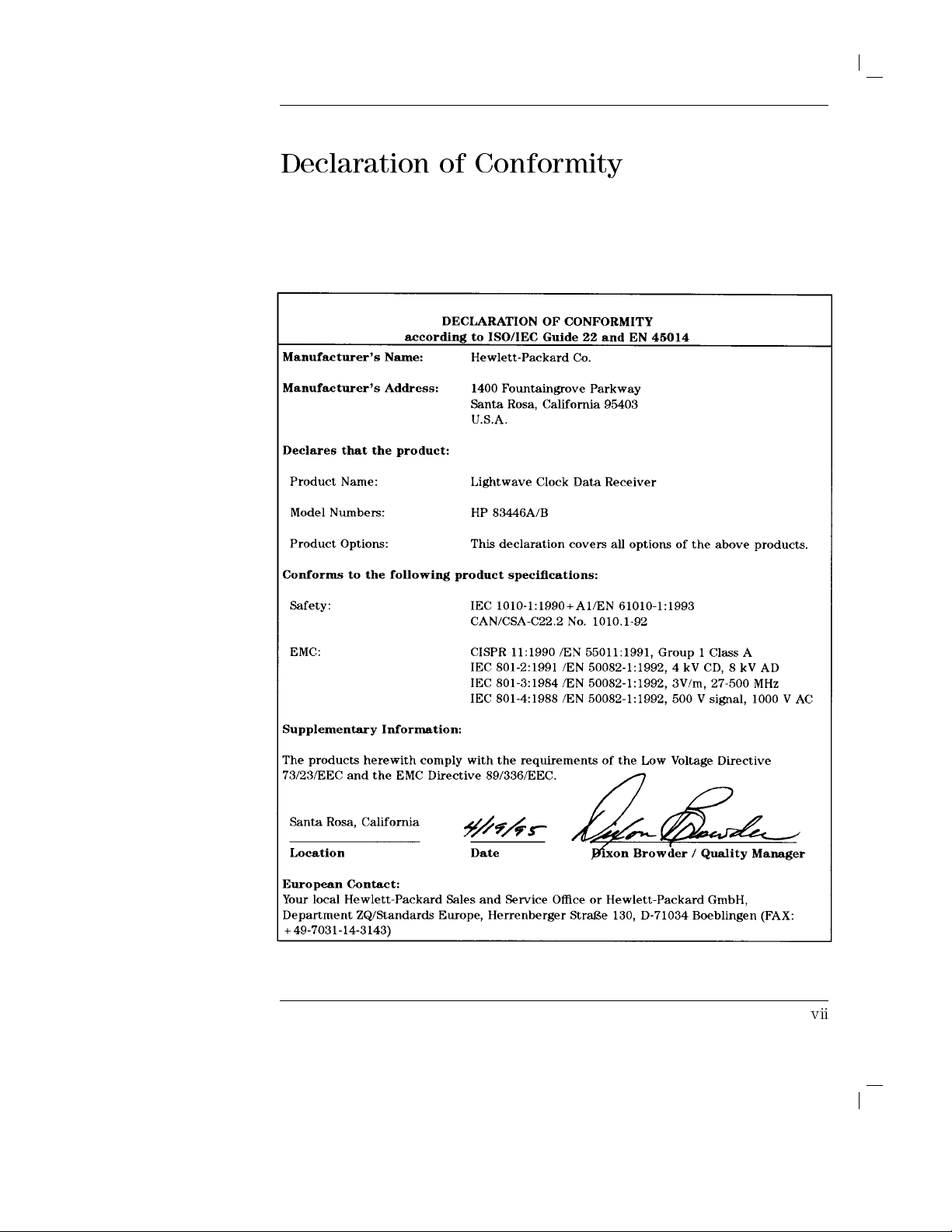
Declaration
of Conformity
vii
Page 8

W
arranty
This
Agilent T
material
During
repair
F
or warranty
facility
charges
charges
charges
another
and workmanship
the warranty
or replace
designated
to
to
, duties
country
echnologies
products which
service or
Agilent
return
,
the
and
.
instrument
for
period, Agilent
repair
by
Agilent
T
echnologies
product
taxes
for
product
a
period
T
echnologies
prove
,
this
product
T
echnologies
and
Agilent
to
Buyer
products
of
one
to
be
must
.
Buyer
T
.
However
returned
is
warranted
year
from
will,
defective
be
returned
.
shall
echnologies
,
Buyer
to
Agilent
against
date
at
its
prepay
shall
shall
T
defects
of
shipment.
option,
to
a
service
either
shipping
pay
shipping
pay
all
shipping
echnologies
in
from
Agilent T
Agilent T
instructions when
does not
rmware
Limit
The
or
interfacing,
environmental
or
NO
TECHNOLOGIES
OF
Ex
THE
REMEDIES
ANY
echnologies warrants
echnologies for
warrant that
will
be uninterrupted
a
tion
of
W
foregoing
inadequate
unauthorized
maintenance
OTHER
W
ARRANTY
MERCHANT
clusive
Remedies
REMEDIES
.
A
GILENT TECHNOLOGIES
DIRECT, INDIRECT
properly installed
arranty
warranty
maintenance
specications
.
SPECIFICALL
ABILITY
PRO
DAMAGES, WHETHER B
LEGAL THEORY
.
use
that its
with
software
an
instrument
on
the
operation
shall
by
or
not
Buyer
of
error-free
apply
modication
for
the
IS
EXPRESSED
Y
DISCLAIMS
AND
FITNESS
VIDED HEREIN
, SPECIAL, INCIDENT
ASED ON CONTRA
and
will
that
instrument.
the
instrument,
.
to
defects
,
Buyer-supplied
or
misuse
product,
OR
,
or
improper
IMPLIED
THE
FOR
A
P
ARTICULAR
ARE BUYER'S
SHALL
NOT
AL, OR CONSEQUENTIAL
CT
, TORT
rmware
execute
designated
its
Agilent
or
software
resulting
from
software
operation
outside
site
.
A
GILENT
IMPLIED
W
ARRANTIES
PURPOSE.
SOLE AND
BE
LIABLE
, OR ANY OTHER
by
programming
T
echnologies
,
or
improper
or
of
the
preparation
EXCLUSIVE
FOR
viii
Page 9
Contents
1.
General
Description
F
ron
Rear
Agilen
Electrostatic
Reducing
2.
Installation
Installing
Step
Step
Step
Step
Step
Connecting
T
P
erforming
If
Ho
w
P
Instrumen
Sales
Cleaning
T
T
T
T
Information
t-panel
panel
t
83446A/B
the
1.
Insp
2.
Set
3.
Chec
4.
Connect
5.
T
urn
est
Set
a
the
v
erication
to
Return the
ac
k
aging
and service
Connections for
o clean
o clean
o test
o
a
an adapter
insertion loss
test
return
of
the
Agilen
features
features
Sp
Disc
harge
ESD
damage
and
Preparation
Agilen
ect
the
the
line
k
the
the
on
the
the
Agilen
.
. .
.
Quic
k
Agilent
.
. .
t
shipping
non-lensed
loss
t
83446A/B
.
.
.
.
.
.
.
.
.
.
ecications
Information
.
t
83446A/B
shipmen
v
oltage
fuse
.
Agilen
Agilen
t
83446A/B
.
.
.
Condence Chec
c
heck
fails
. .
.
preparation
oces
Accurate
connector
.
.
.
.
.
.
.
and
.
.
.
for
Use
.
t
.
selector
.
.
. .
t
83446A/B
t
83446A/B
.
.
.
.
83446A/B for
.
.
.
.
.
.
.
.
.
.
.
.
.
.
.
.
.
.
.
.
.
.
.
.
.
.
.
.
.
Characteristics
.
.
.
.
.
.
.
.
.
.
.
.
.
.
.
.
.
.
.
.
. .
. .
.
.
to
a
.
.
to
a
Bit-Error-Ratio
.
.
.
.
.
k
.
.
.
.
.
.
.
.
Service
.
.
.
.
.
pro
cedure
.
.
.
.
.
Measuremen
.
.
.
.
.
.
.
.
.
.
.
.
.
.
.
.
.
.
. .
.
.
.
.
.
.
.
. .
.
po
. .
.
.
.
.
.
.
ts
.
.
.
. .
.
.
.
.
.
.
.
.
wer
.
.
.
.
.
.
.
.
.
.
.
.
.
.
.
.
.
.
.
.
.
.
. .
.
.
.
.
source
.
.
.
.
.
.
.
.
.
.
.
.
.
.
.
.
.
.
.
.
.
.
.
.
. .
.
. .
.
.
.
. .
. .
. .
.
.
.
.
.
.
.
.
.
.
.
.
.
.
. .
.
1-3
1-6
.
1-8
.
1-9
.
1-12
1-14
2-3
2-3
.
2-5
.
2-6
2-7
.
2-10
.
2-11
.
2-13
.
2-13
.
2-15
.
2-15
.
2-16
.
2-17
.
2-19
.
2-21
.
2-22
.
2-23
2-23
3. Using
the Agilent 83446A/B
Bit-Error-Ratio T
Example of measuring disp
single-mode b er .
System sensitivity calibration .
Determining dispersion po
Bit-Error-Ratio T
est
. . . . . . . . . . . . . . . . .
est .
ersion po
. . . . . . . .
wer penalt
. . . . . . . . . . . .
wer penalt
. . . . . . .
. . . . . . . . .
y . . . . .
yof
. . . .
. .
. . .
Contents-1
3-3
3-3
3-4
3-7
3-10
Page 10
Replaceable
parts
W
4.
Servicing
General
T
Adjustmen
P
Replacemen
Replaceable
Example
aveform
Example
roublesho
P
o
w
Photo
erformance
T
est
T
est
T
est
T
est
T
est
Replacing
Replacing the
Replacing
Replacing
of
T
est
of
signal
the
information
oting
t
er
supply
detector/clo
pro
cedure
1.
Sensitivit
2.
Maximum
3.
Electrical output
4.
Rear-panel
c
hec
k
only)
5.
Input
t
optimizing
.
.
.
measuring
.
.
.
.
Agilent
.
.
Pro
cedures
adjustmen
.
.
T
ests
.
y
.
optical
Pro
cedures
the
RF
ac
cable
the
p
o
w
the
PCDR
parts
.
laser
.
.
.
ey
e
.
.
.
83446A/B
.
.
.
.
.
.
.
t
c
k/data
.
.
. .
.
.
.
.
.
.
operating
input
.
.
.
return
.
cable
or
assem
er
supply
assem
.
.
.
extinction
.
.
.
.
diagram
.
.
.
.
.
.
. .
. .
.
.
.
pro
cedure .
reco
v
ery
. .
.
.
.
.
.
.
input p
signal amplitudes
p
ort
v
erication
.
.
.
loss
.
.
.
the
RF
bly
.
.
bly
.
.
.
ratio
..
..
using
.
.
.
. .
. .
. .
. .
. .
assem
.
.
.
.
. .
.
.
.
o
w
er
.
.
.
.
.
.
.
.
.
connector
.
.
.
.
.
.
.
.
.
.
.
.
.
. .
. .
.
.
.
.
.
.
.
.
.
.
.
.
.
.
..
..
.
.
reco
v
ered
clo
.
. .
. .
. .
. .
. .
.
.
.
.
.
.
.
. .
. .
.
.
. .
. .
.
bly adjustmen
.
.
.
.
.
.
.
.
.
.
.
.
.
.
.
.
.
.
.
.
.
.
.
.
. .
. .
.
(functional
.
.
.
.
.
.
.
.
.
.
.
.
.
.
.
.
.
.
.
.
.
.
.
.
.
.
.
.
.
.
.
.
.
. .
.
.
.
.
.
.
.
.
.
.
.
. .
.
3-11
.
3-13
c
k
3-13
.
4-3
.
4-5
.
4-8
.
4-8
t
.
4-10
.
4-11
.
4-15
.
4-20
.
4-21
.
4-23
.
4-24
.
4-26
.
4-27
.
4-28
4-30
.
4-31
4-32
Index
Contents-2
Page 11

Figures
1-1.
1-2.
1-3.
1-4.
2-1.
2-2.
2-3.
2-4.
3-1.
3-2.
3-3. Setup
3-4. Setup
4-1.
4-2.
4-3.
4-4.
4-5.
4-6.
4-7.
Agilent 83446A/B
The Agilent
The Agilent
Example of
Opening the
Selecting
A
C
power
Connecting
system.
Setup
Setup
ber.
clock. .
Agilent
Laser
Agilent
Wiring
Wiring
Agilent
Agilent
83446A/B
83446A/B rear
a static-safe
fuse holder
the
line
cables
the
..
for
calibration
to
measure
..
..
for optimizing
for measuring
..
83446A/B block
transmitter
83446A/B
diagram
Diagram
83446A/B
83446A/B
block
front-panel.
voltage
available
Agilent
.
.
.
of
dispersion
.
.
laser
eye
.
.
.
setup
test
equipment
for
the
for
the
assembly
replaceable
diagram.
panel.
work
station.
door
.
value
.
.
.
83446A/B
.
.
.
.
dispersion
power
.
.
.
.
extinction
diagram
.
.
.
.
diagram.
.
.
.
.
line
module
power
supply
level
hardware
.
.
.
.
.
.
.
.
.
.
.
.
.
and
checking
.
.
.
.
to
a
bit
.
.
.
.
power
penalty of
.
.
.
.
ratio
by
triggering
.
.
.
.
.
.
.
.
.
.
.
setup
.
.
.
.
terminals
replaceable
.
.
.
.
.
.
.
.
.
.
.
.
.
.
.
.
the
.
.
.
error
.
.
.
penalty
.
.
.
.
.
.
.
.
.
.
.
.
.
.
.
.
.
.
.
.
.
parts
.
.
.
.
.
.
.
.
.
.
.
.
.
.
.
.
.
.
.
.
.
.
.
fuse
.
.
.
..
ratio
test
.
.
.
.
.
test
system.
single-mode
.
.
.
.
..
.
.
.
.
from
recovered
.
.
.
.
.
.
.
.
.
.
.
.
.
.
.
.
.
.
.
.
.
.
.
.
.
.
.
.
.
.
.
.
.
.
.
.
.
.
.
.
.
.
.
.
.
..
.
.
.
.
.
..
.
.
.
.
.
.
.
.
..
.
1-4
.
1-6
.
1-8
.
1-13
.
2-5
.
2-6
. 2-9
.
2-11
3-4
. 3-7
.
3-12
.
3-14
.
4-5
.
4-12
.
4-16
.
4-28
.
4-30
.
4-34
. 4-36
Contents-3
Page 12
T
ables
1-1.
Agilent 83446A/B
1-2.
Static-Safe A
2-1.
Agilent 83446A/B
2-2.
Agilent T
3-1.
Average
4-1.
Required
4-2.
V
oltages
4-3.
Required
4-4.
Laser Transmitter
4-5.
Sensitivity
4-6.
Input
4-7. T
orque V
4-8. Line
4-9. DC
Gating P
Optical
alues .
Module to
Power
4-10. Assembly-Level
4-11.
Replaceable
Specications
ccessories
Power
.
.
Requirements
echnologies Service
eriod
to
A
T
ools
.
.
.
.
.
on
the
DC
P
ower
T
est
Equipment
T
est
Setup
Return
DC
Supply
Setup
.
.
T
erminal
Loss
.
P
ower
.
.
.
.
.
.
Replaceable P
Hardware .
.
and
.
.
.
.
Numbers
chieve
Supply
Supply
.
.
.
.
.
.
.
.
.
.
..
.
.
.
.
.
.
100
.
T
erminals
.
.
.
..
.
Connections
Connections
arts
.
.
.
.
.
Characteristics
.
.
.
.
.
.
.
.
.
.
.
.
.
.
.
Errors
.
.
.
.
.
.
.
.
..
.
.
.
.
.
.
.
..
.
.
.
.
.
.
.
.
.
.
.
.
.
.
.
.
.
.
.
.
.
.
.
.
.
.
.
.
.
.
.
.
.
.
.
.
.
.
.
.
.
.
.
.
.
.
.
.
.
.
.
.
.
.
.
.
.
.
.
..
.
.
.
.
.
.
.
.
.
..
.
.
.
.
.
.
.
.
.
.
.
.
.
.
.
.
.
.
.
.
.
.
.
..
.
.
.
..
.
.
.
.
.
.
..
.
.
.
.
.
.
.
.
.
1-10
.
1-14
.
2-7
.
2-18
.
3-5
. 4-4
. 4-7
4-11
.
4-13
.
4-17
.
4-24
4-27
.
4-29
.
4-30
.
4-35
.
4-37
Contents-4
Page 13

1
General
Information
Page 14
General
What
you'll nd
A
brief
description
A
list
of
options and
Agilent
83446A/B
Information
Information
Information
in this
chapter
of the
Agilent 83446A/B
accessories available
about
about
specications
the
lightwave
avoiding
and characteristics.
receiver's
damage
to
lightwave clock/data
.
serial number
the
instrument
receiver.
label.
from electrostatic
discharge
.
1-2
Page 15
Description
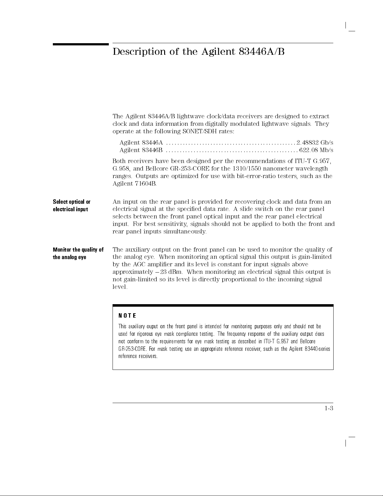
The
Agilent 83446A/B
clock
operate
and data
at the
information
following SONET/SDH
of
the
lightwave
Agilent 83446A/B
from
clock/data
digitally
receivers
modulated
rates:
are
designed
lightwave
to
signals
extract
.
They
Select
optical
electrical
Monitor
the
analog
input
the
quality
eye
Agilent
Agilent
Both
G.958,
ranges
Agilent
An
or
input
electrical
selects
input.
rear
The
of
the
by
the
approximately
not
83446A
83446B
receivers
and
Bellcore
.Outputs
71604B
on
the
signal
between
F
or
best
panel
inputs
auxiliary
analog
A
GC
eye
amplier
gain-limited
:
::
:
:
:
::
:
:
have
been
GR-253-CORE
are
optimized
.
rear
panel
at
the
specied
the
front
sensitivity
simultaneously
output
.
When
on
monitoring
and
0
23
dBm.
so
its
level
:
:
:
:
:
:
:
:
:
:
designed
is
panel
,
signals
the
its
When
is
:
:
:
:
:
:
:
:
:
:
:
:
for
provided
data
optical
.
front
level
monitoring
directly
:
:
:
:
::
:
:
:
:
::
per
the
for
the
use
with
for
rate
input
should
panel
an
optical
is
constant
proportional
::
::
::
:
:
:
:
:
:
:
::
::
::
:
:
:
:
:
:
:
:
recommendations
1310/1550
bit-error-ratio
recovering
.
A
slide
switch on
and
the
not
be
applied to
can
be
used
to
signal
this
for
input
an
electrical
to
:
:
:
:
:
:
:
:
:
:
:
:
:
:
:
:
:
:
:
of
nanometer
testers
clock
and
the rear
rear
panel electrical
both the
monitor
output
signals
signal
the
incoming
::
2.48832 Gb/s
::
:
622.08
ITU-T
G.957,
wavelength
,
such
as
data
from
panel
front
the
quality
is
gain-limited
above
this
output
signal
Mb/s
the
an
and
of
is
level.
NO
T
E
This
auxiliary
ouput on
used
for rigorous
not conform to the requirements for e
GR-253-CORE. F
e
ye
the front
mask
panel is
compliance
intended for
testing.
monitoring purposes
The
frequenc
y
response
ye mask testing as described in ITU-T G.957 and Bellcore
or mask testing use an appropriate reference receiver
of
only and
the
should
auxiliary output
not
be
does
, such as the Agilent 83440-series
reference receivers.
1-3
Page 16

General
Information
Description of
F
or
more
Chapter
3.
the Agilent
information
83446A/B
on
using
the
lightwave
clock/data
receiver
refer
to
Learning the
story
.
.
.
inside
The block
The
photodetector
The
single-mode
when
diagram
for
optical-to-electrical
which
optical
used
input
or
multimode
with
uses
62.5
automatic-gain-control
switch,
receiver's
hybrid.
circuit. The
signal.
signal.
interface
is
split
front
The
data
Clock
The
phase
is
maintained
into
panel.
clock
and
two
signal
is
threshhold-detected
data
relationship
the
Agilent
conversion
covers
50
the
m
ber
m
ber
(A
GC)
paths
The
other
is
recovered
outputs
to
approximately
83446A/B
is
performed
1310
and
multimode
inputs
.
.)
The
photodetector
amplier
.
One
path
path
using
are
noninverting
between
1550
ber
(A
slight
and,
provides
goes
and
the
6
0.25
is
shown
by
nm
for
loss
after
to
the
a
phase
re-timed
with
two
outputs
unit
going
in
Figure
a
sensitive
wavelength
compatability
in
sensitivity
output
is
amplied
through
an
auxiliary
clock
and
data
and
frequency-locked
to
the
recovered
respect
at
the
intervals
.
1-1
APD
ranges
with
the
output
to
the
front
.
.
either
results
in
MMIC
on
recovery
clock
incoming
panel
an
the
loop
1-4
Figure 1-1. Agilent 83446A/B block diagram.
Page 17
Description of
General
the Agilent
Information
83446A/B
Accessories
Options
Serial
Numbers
supplied
The
Agilent 83446A/B
P
ower cable
FC/PC
A
gilent 83446A/B
The
following
Option
The
010
Fiber
introduction
Agilent
their
T
echnologies service
Technologies
performance,
changes
Whenever
have
the
complete
A
serial-number
It
contains
receiver
.
information
number
.
(refer to
front-panel connector
option
Optics Handbook
and
to
each
you
contact
complete
and
accurate
the
serial
Whenever
about
lightwave clock/data
Figure 2-3
interfaces
Lightwave Clock/Data
is
available:
Deletes FC/PC
front-panel connector
, Agilent
reference
for
ber-optic measurements
makes frequent
usability,
or reliability
personnel have
type
of
equipment,
Agilent
serial
number
T
echnologies
information
label
is
attached
number
you
your
and
specify
lightwave
the
)
part number
improvements
, and
access to
based
available
possible
to
the
rear
the
options
serial
receiver
,
receiver is
Receiver
User
5952-9654, is
to
to
control
complete records
on
the
equipment's
about
your
to
ensure
obtaining
.
of
the
lightwave
installed
number
be
sure
or
to
shipped with:
and
Service
interface
an
.
its
products
costs
.
Agilent
of
serial
lightwave
the
receiver
in
the
lightwave
refer
to
it
in
use
the
complete
Guide
to
enhance
design
number
receiver
most
.
obtaining
.
.
,
1-5
Page 18
General
Information
Description of
Front-panel features
the Agilent
83446A/B
1-6
Figure
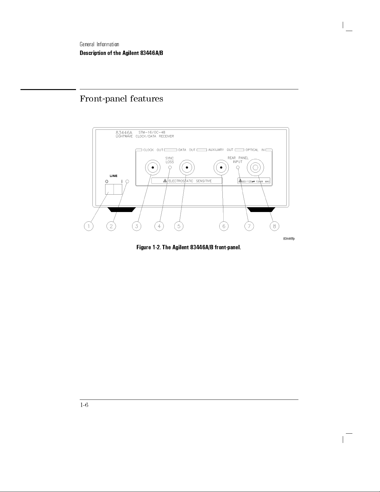
1-2.
The
Agilent
83446A/B
front-panel.
Page 19
1.
Line
switch.
2.
P
owerline
3.
CLOCK
for
Agilent
output is
synchronized
clock
frequency
4.
SYNC
LOSS
synchronized
remain
at
DATA
5.
DATA
OUT
corresponding
clock
transitions
6.
AUXILIARY
version
is
amplitude
0
23
dBm.
stabilized
of
the
LED
.
OUT
connector
83446B).
synchronized
to
an
.
indicator
to
the
synchronized
OUT.
connector
to
OUT
connector
of
the
input
stabilized
When
so
its
output
incoming
signal.
the
to
used
input
.
6
.
Output
When
with
signal
.
This
bit
rate
to
input
This
incoming
0.25
signal.
for
with
amplitude
the
the
LED
of
signals
output
unit
.
This
When
input
an
is
nominally
SYNC
LOSS
bit
rate
the
output
is
o
whenever
the
input
provides
data
stream.
intervals
output
used
signals
electrical
is
directly
indicator
of
signal.
several
.
provides
with
greater
input
Description of
2.48832
GHz
is
the
input
free-runs
the
clock
Note
dB
below
an
amplied,
Data
transitions
a
non-retimed
an
optical
than
this
output
proportional
General
the Agilent
(622.08
MHz
extinguished
signal.
near
that
the
output
CLOCK
the
onset
retimed
When
nominal
is
signal
are
aligned
analog
input
this port
approximately
is
not
amplitude
to
the
amplitude
Information
83446A/B
this
not
OUT
can
of
errors
to
7.
REAR
switch
8.
OPTICAL
input
adapters
PANEL
on
IN
is
+10
from the
INPUT
the
rear
connector
dBm.
indicator
panel
This
.
This
is
set
to the
.
Maximum
input accepts
LED is
signal
Agilent 81000-series
REAR
input is
any of
.
on
when
position.
0
9
the connector
the
dBm,
input
damage
selector
level
interface
1-7
Page 20
General
Information
Description of
the Agilent
83446A/B
Rear panel
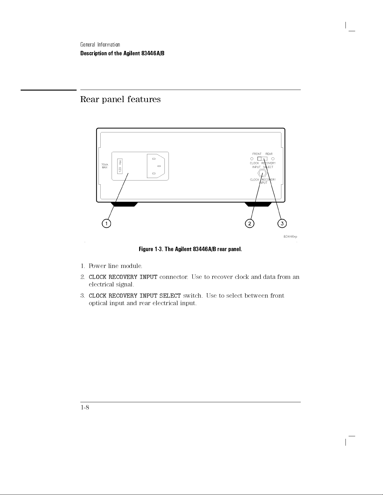
1.
P
ower
line
2.
CLOCK
electrical
RECOVERY
signal.
features
Figure
module
.
INPUT
1-3.
The
connector
Agilent
83446A/B
.
Use
to
recover
rear
panel.
clock
and
data
from an
3.
1-8
CLOCK
optical
RECOVERY
input
and
INPUT
rear
SELECT
electrical
switch.
input.
Use
to
select
between
front
Page 21
Agilent
83446A/B
istics
T
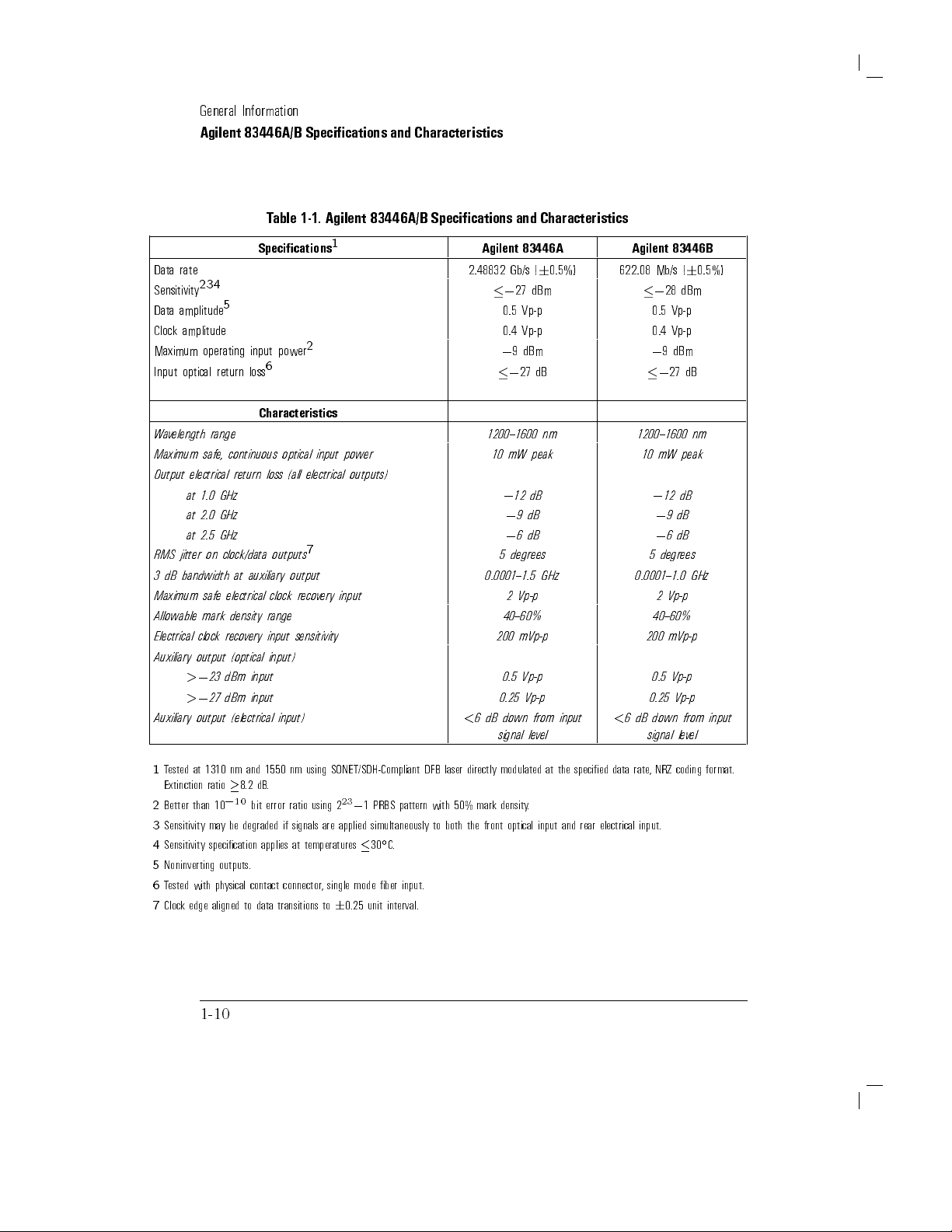
able 1-1
values
Specications describe
range
after
continuous
Characteristics
nonwarranted,
lists
specication,
. The
distinction
C
0
to +55
the instrument's
operation.
provide
performance parameters
italics.
Typical
Performance
performance which
Nominal
Value
indicates
parameter.
Specications
characteristics
between
these
warranted performance
C
(unless otherwise
temperature has
useful
information
,
where
most units
the
listed,
will meet.
expected,
,
typical
terms
noted). All
been
.
Characteristics
is
not
warranted
but
is
described
over
stabilized
by
giving
not
warranted
and Character-
performance
the
specications
functional,
,
but
,
and
as
follows:
temperature
apply
after
30
minutes
but
are
printed
indicates
,
value
of
nominal
in
the
of
1-9
Page 22
General
Agilent 83446A/B
Data
rate
2
Sensitivity
3
Data amplitude
Clock
amplitude
Maximum
Input
W
Maximum
Output
RMS
3
Maximum
Allowable
Electrical
a
v
elength
dB
operating
optical
range
safe
electrical
at
1.0
at
2.0
at
2.5
jitter
on
bandwidth
safe
mark
clock
Auxiliary output
>
0
23
>
0
27
Auxiliary
output
Information
4
5
input
return
loss
,
continuous
return
GHz
GHz
GHz
clock/data
at
auxiliary output
electrical
density range
reco
v
ery
(optical
dBm
input
dBm
input
(electrical input)
Specications and
T
able
1-1.
Specications
2
power
6
Characteristics
optical
input
loss
(all
electrical
7
outputs
clock
reco
v
ery
input
sensitivity
input)
Agilent
1
power
outputs)
input
Characteristics
83446A/B
Specications
Agilent
2.48832
0
0
1200{1600
10
0.0001{1.5
200
<
6
dB down
signal
and
Characteristics
83446A
Gb/s
27
(
6
dBm
0.5%)
Agilent
622.08
0
83446B
Mb/s
28
0.5 Vp-p 0.5 Vp-p
0.4
0
mW
0
0
0
5
degrees
2
9
12
Vp-p
dBm
27
9
6
Vp-p
dB
nm
peak
dB
dB
dB
GHz
0.4
Vp-p
0
9
dBm
0
27
1200{1600
10
mW
0
12
0
9
0
6
5
degrees
0.0001{1.0
2
Vp-p
40{60% 40{60%
<
6
dB down
200
0.5
0.25
signal
mVp-p
Vp-p
Vp-p
0.5
0.25
mVp-p
Vp-p
Vp-p
from input
lev
el
(
6
0.5%)
dBm
dB
nm
peak
dB
dB
dB
GHz
from input
lev
el
1
T
ested
at
1310
nm
and
1550
nm using
Extinction ratio
2
Better than
3
Sensitivity
4
Sensitivity specication applies
5
Noninverting outputs.
6
Tested with ph
7
Clock edge aligned to data transitions to
8.2
dB
.
0
10
bit
10
may
error ratio
be degraded
ysical contact connector
if signals
at temperatures
1-10
SONET/SDH-Compliant DFB
23
0
using 2
1 PRBS
are applied
,
simultaneously to
C.
30
single mode ber input.
6
0.25 unit interval.
pattern with
laser directly
50% mark
both
the
front
modulated
density.
optical
input
at
the
specied
data
rate
,
NRZ
coding
format.
and
rear
electrical
input.
Page 23
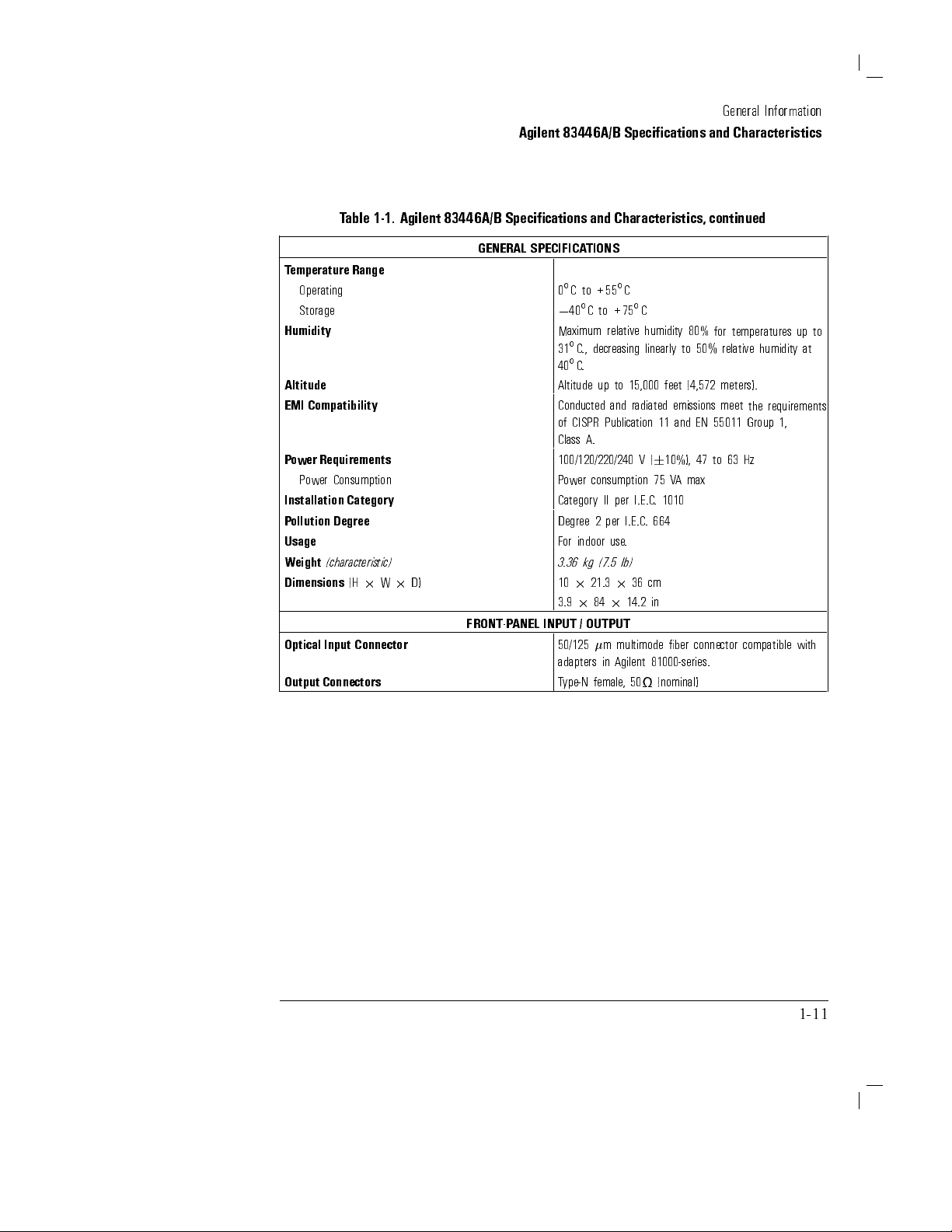
T
able
1-1.
Agilent
83446A/B
Agilent 83446A/B
Specications
Specications and
and
Characteristics,
General
Characteristics
continued
Information
T
emperature
GENERAL
Range
SPECIFICA
Operating 0C
Storage
Humidity
Altitude
EMI
Compatibility
P
ower
Requirements
P
ower
Consumption
Installation
P
ollution
Category
Degree
Usage
Weight
(characteristic)
Dimensions
Optical
Output
(H
2
Input
Connector
Connectors
W
2
D)
FRONT-P
ANEL
TIONS
to
0
40Cto
Maximum
31C
.,
40C
.
Altitude up
Conducted
of
CISPR
Class
A.
100/120/220/240
P
ower
Category
Degree
F
or indoor
3.36
kg
10
2
3.9
2
INPUT
/
OUTPUT
50/125
adapters
T
ype-N
C
+55
+75
relative humidity
decreasing
to 15,000
and radiated
Publication 11
consumption
II
per
I.E.C
2
per
I.E.C
use
.
(7.5
lb)
21.3
2
36
84
2
14.2
m
multimode
in
Agilent
female
,
50
C
linearly
feet (4,572
V
(
6
10%),
75
V
.
1010
.
664
cm
in
ber
81000-series.
(nominal)
80%
to 50%
emissions
and EN
47
A
max
connector
for
temperatures
relative humidity
meters).
meet
the
55011
Group
to
63
Hz
compatible
up
to
at
requirements
1,
with
1-11
Page 24

Electrostatic
Discharge
Information
Electrostatic
All
work on
station.
types
of ESD
Conductive table-mat
Conductive
Both
types
Of
the two
ESD
protection
To
ensure user
of isolation
static-safe accessories
W
A
R
N
I
N
G
These
working
discharge (ESD)
electronic
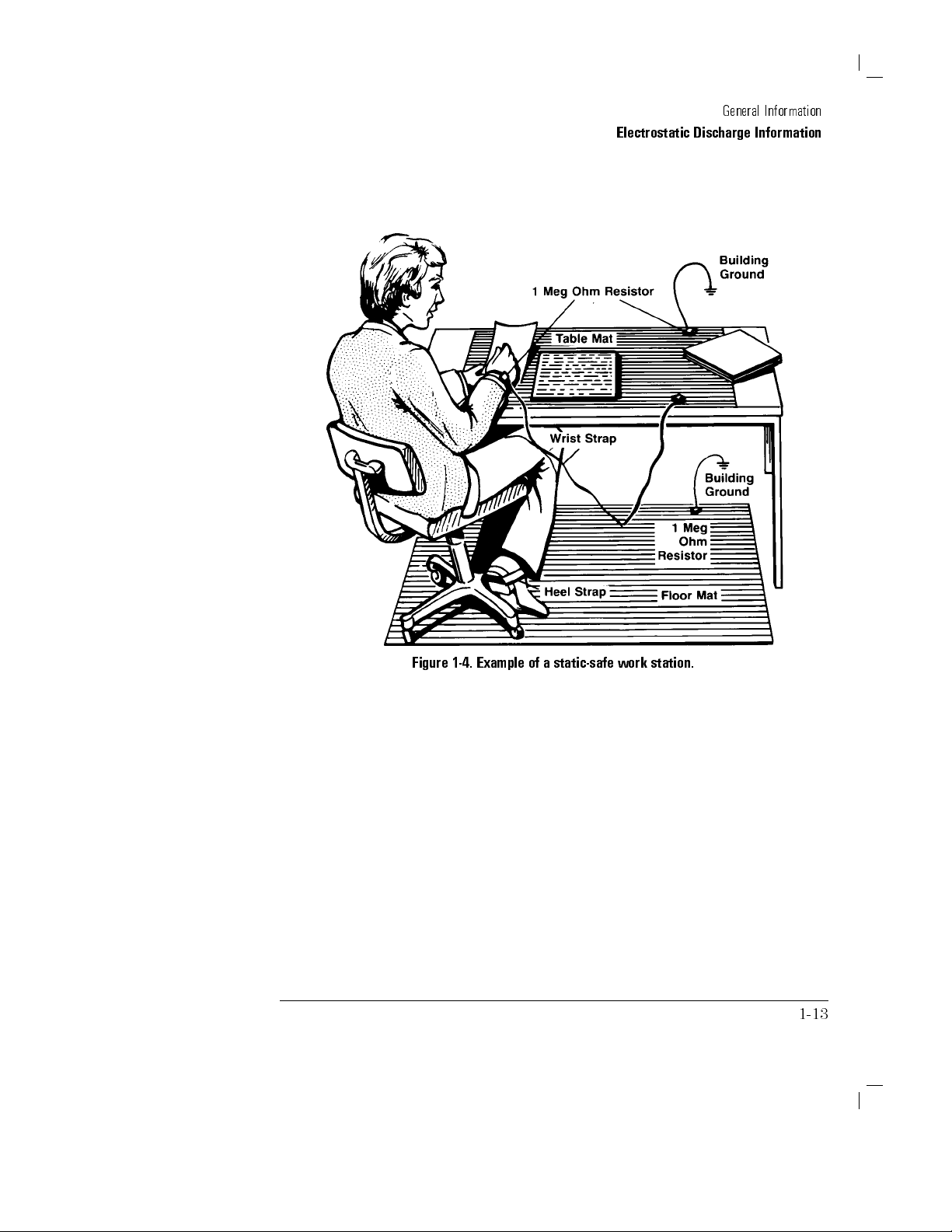
Figure 1-4
protection:
oor-mat
,
when
,
only
when
safety,
from ground.
techniques
on
circuitry
shows an
used
the
table-mat
used
.
for
can
assemblies
example
and wrist-strap
and
heel-strap
together
,
provide
and
alone
.
the
static-safe
Refer
to
a
static-safe
with
a
voltage
damage
should
of
combination.
combination.
wrist-strap
accessories
T
able
1-2
work
potential
or
destroy
be
performed
a
static-safe
a
signicant
combination
for
station
electronic
at
work
level
must
provide
information
should
greater
not
than
components
a
static-safe
station
of
ESD
provides
at
on
ordering
be
used
500
work
using
protection.
adequate
least
1
M
when
volts
.
.
two
1-12
Page 25
General
Electrostatic Discharge
Information
Information
Figure
1-4.
Example
of
a
static-safe
work
station.
1-13
Page 26

General
Information
Electrostatic Discharge
Information
Reducing ESD
The following
testing and
Before
time each
suggestions may
servicing operations
connecting any
day
damage
coaxial cable
,
momentarily
help
.
ground
reduce
to
the
cable.
P
ersonnel
touching
assembly
Be
sure that
buildup of
T
able
1-2 lists
T
echnologies
Agilent
should
the
from
static charge
Part
be
grounded
center
all instruments
the
pin
unit.
of
any
are
.
static-safe accessories
using the
Agilent part
T
able
1-2.
with
a
resistor-isolated
connector
properly
that
numbers
Static-Safe
Number Description
9300-0797 Set
9300-0980 Wrist-strap
wire
includes:
.
(The
3M
static
wrist-strap
cord
1.5
m
control
and
(5
mat
wrist-strap
ft).
0.6
cord
ESD
damage
an
instrument
center
and
and
before
earth-grounded
can
be
obtained
shown.
Accessories
m
2
1.2
m
(2
are not
included. The
outer
removing
ft
2
4
that
occurs
connector
conductors
wrist-strap
to
prevent
from
Agilent
ft)
and
4.6
y
must
be
for
any
cm
(15
ordered
during
the
of
before
a
ft)
separately
rst
the
ground
.)
9300-1383 Wrist-strap
post-type connection.
9300-1169 ESD heel-strap
1-14
,
color
black,
(reusable 6
stainless
to 12
steel, without
months).
cord, has
four adjustable
links and
a
7
mm
Page 27

2
Installation
Preparation for Use
and
Page 28
Installation
What
you'll nd
Installing
Connecting
How
to
How
to
Cleaning
This
instrument
Publication
and
has
been
contains
ensure
safe
in this
the
Agilent
the
Agilent
perform
aquick
return
the
Agilent
connections
has
61010,
supplied
information
operation
and Preparation
chapter
83446A/B.
83446A/B lightwave
condence check
83446A/B for
for
accurate
measurements.
been
designed
Safety
in
and
and
warnings
R
equirements
a
safe
to
maintain
clock/data receiver
of the
Agilent 83446A/B
service.
and tested
for Electronic
condition. The
which
must
the
instrument
for Use
to a
bit-error-ratio tester
.
in accordance
Measuring Apparatus
instruction
be
followed by
in a
.
with
IEC
documentation
the
user
safe
condition.
,
to
2-2
N
O
Clean
T
E
the
cabinet
using
a
damp
cloth
only
.
Page 29

Installing
the
Agilent
83446A/B
C
A
U
T
I
O
N
VENTILA
the
ambient
operating
dissipated
greater
C
A
T
I
O
N
This
Degree
Step
Inspect
If
the
you
lightwave
The lightwave
to
numbers
of
the
lightwave
TION
convection
temperature
temperature
than
product
2per
1.
the
shipping
have
veried
receiver
Return
the
of
Agilent
receiver
REQUIREMENTS:
into
and
out
(outside
of
in
the
cabinet.
800
watts
,
then
is
designed
IEC
1010
and
Inspect the
lightwave
clock/data
container
that
the
mechanically
clock/data
Agilent
the
83446A/B
packaging
83446A/B"
.
When
of
the
the
the
instrument
If
the
total
forced
for
use
in
664
respectively
shipment
receiver
or
cushioning
contents
and
receiver
for
materials
in
Chapter
installing
instrument
cabinet)
by
power
convection
Installation
shipping container
material
are
complete
electrically
is
packed
Service
.
Refer
1,
for
the
must
must
be
C
for
4
dissipated
must
Category
.
is
and
.
within
",
for
the
to
\A
ccessories"
the
accessories
instrument
not
be
less
than
every
in
the
be
used.
II
damaged,
you
have
a
carton.
description
in
restricted.
the
maximum
100
watts
cabinet
and
P
ollution
for
damage
keep
it
tested
Refer
and
in
\Description
shipped
a
cabinet,
The
is
until
the
to
\How
part
with
.
the
If
the
contents
verication
Check"),
container is damaged or
notify the carrier
The Agilent T
are
incomplete
test
(this
procedure
notify
the
nearest
the cushioning material shows signs of stress
.K
eep the shipping materials for the carrier's inspection.
echnologies oce will
or
is
Agilent
if
the
lightwave
provided
Technologies
receiver
in
\Performing
oce.
does
a Quick
If the
not
pass
Condence
shipping
,also
arrange for repair or replacement without
waiting for a claim settlement.
If the shipping materials are in good condition, retain them for possible
future use
.Y
ou may wish to ship the lightwave receiver to another location
the
2-3
Page 30

Installation
Installing the
or
Agilent
and
return
83446A/B
Preparation
Agilent 83446A/B
it
to
for
Agilent
for
Use
T
echnologies
Service
".
for
service
.
Refer
to
\How
to
Return the
2-4
Page 31

Installation
and
Installing the
Preparation
for
Use
Agilent 83446A/B
CA
Step 2.
Use the
selector to
available ac
U
T
I
O
N
Before connecting
the rear-panel
the
power
receiver
1.
Pry
Set the
line
following procedure
the voltage
range (100,
voltage.
the
lightwave
when
open
voltage
source
it is
the
.
An
fuse
selector
improper
turned
holder
voltage
to
set
receiver
correctly
selector
on.
door
the
120,
with
selector
lightwave
220,
or
to
the
to
adapt
setting
a
small
screwdriver
clock/data
240V)
corresponding
power
the
lightwave
can
damage
source
.
receiver's
,
you
must
receiver
the
lightwave
voltage
to
the
set
to
Figure
2-1.
Opening
Y
ou
C
A
U
T
I
O
N
must remove
the
voltage
2.
Remove
the voltage
tumbler while
the
voltage
tumbler
tumbler to
it is
in the
(the
the
fuse
change the
line module
voltage
tumbler
holder
damages
door
.
voltage
is
not
selector
the
line
attached
.
Rotating
module
to the
.
unit).
3. Replace the
through the small
voltage tumbler so the desired line voltage value shows
opening in the fuse holder door
.
2-5
Page 32

Installation
and
Installing the
Preparation
for
Use
Agilent 83446A/B
Step 3.
The recommended
F
or a
Check the
fuse is
listed
100/120V operation:
fuse
T
below:
0.315A,
250V
,
time
delay
,
Agilent
part
number 2110-0449.
F
or
a
220/240V
operation:
T
0.16A,
250V
,
time
delay
,
Agilent
part
number
2110-0448.
F
or
W
A
R
N
I
N
G
continued
same
The
(refer
T
o
check
and
gently
If
the
and
reinsert
type
line
to
fuse
and
fuse
Figure
the
fuse
pull
is
defective
the
protection
ratings
is
housed
2-2
).
The
,
insert
outward
fuse
against
.
The
use
in
a
small
spare
the
tip
to
remove
or
missing,
container
re
of
container
fuse
of
install
.
hazard,
other
fuses
is
stored
a
screwdriver
the
container
a
new
replace
next
below
or
materials
to
the
the
on
.
fuse
line
voltage
line
the
side
in
the proper
fuse
only
is
prohibited.
tumbler
fuse
.
of
the
with
container
position
2-6
Figure 2-2. Selecting the line voltage value and checking the fuse.
Page 33

Installation
Installing the
and
Preparation
Agilent 83446A/B
for
Use
C
P
ower
W
Step 4.
Connect the
Agilent
83446A/B
to
a
power
source
The
lightwave
physical
Do
not
A
U
T
I
O
N
correct,
connect
the
properly
equipment
clock/data
installation
ac
proper
positioned,
could
result.
other
power
fuse
as
T
able
receiver
than
until
you
is
installed,
described
2-1. Agilent
is
a
portable
connection
have
veried
and
the
in
the
following
83446A/B P
instrument
to
a
power
line
that
the
voltage
source
selector
paragraphs
ower Requirements
and
line
requires
.
voltage is
switch
.
Damage
to
no
is
the
Characteristic Requirement
Input
V
oltage
Frequenc
y
P
ower
cable
A
R
N
I
N
G
The
lightwave
accordance
appropriate
F
ailure
injury
to
.
Before
protective
cable
.
Insert
a
protective
by
using
an
protective
receiver
is
equipped
with international
power line
ground
turning
earth
the
earth
extension
ground
outlet,
the
lightwave
on
terminals
main
power
contact.
cable
conductor
the
to
,
safety
this
receiver
lightwave
the
protective
cable
Do
not
power
.
100,
120,
75
with a
standards
cable
grounds
plug
defeat
cable
220,
or
240
V
47
to
63
Hz
V
A
(maximum)
three-wire
.
When
the
properly
receiver
,
you
conductor
only
into
the
earth-grounding
,
or
autotransformer
(
6
10%)
power
connected
instrument
can
result
must
of
a
socket
cable
in
connect
the
main
outlet
without
,
in
to
an
cabinet.
personal
its
power
that
has
protection
a
If
you
are
using
an
autotransformer
connected
to
the
protective
socket.
Various power
types of ac power
cables are available to connect the lightwave receiver to the
outlets unique to specic geographic areas
appropriate for the area to
is included with the unit. Y
,
make
earth
contact
sure its
of
common terminal
the
power source
is
outlet
. The cable
which the lightwave receiver is originally shipped
ou can order additional ac power cables for use in
2-7
Page 34

Installation
and
Installing the
Preparation
for
Use
Agilent 83446A/B
dierent
plug
appropriate
C
A
U
T
I
O
N
Always
F
ailure
instrument
areas
.
Figure
congurations
.
use
the
three-prong
to
ensure
damage
2-3
,
and
identies
adequate
.
lists
ac
earth
the
available
the
power
grounding
ac
geographic
cord
supplied
by
power
area
not
with
using
cables
in
which
this
this
,
illustrates
each
instrument.
cord
may
the
cable
cause
is
2-8
Page 35

Installation
Installing the
and
Preparation
Agilent 83446A/B
for
Use
Figure
2-3.
AC
power
cables
available.
2-9
Page 36

Installation
and
Installing the
Preparation
for
Use
Agilent 83446A/B
Step 5.
With the
receiver on
should light.
Turn on
power cable
by pressing
If the
Condence Check"
the
inserted
the line
LED should
in
this
chapter
Agilent
into
the
switch.
fail
to
light,
.
83446A/B
line
module
The
green
refer
to
,
turn
the
lightwave
light-emitting
\P
erforming
diode
a
Quick
(LED)
2-10
Page 37

Connecting
the
Agilent
83446A/B to
a Bit-
Error-Ratio
The
following procedure
receiver
to a
bit
error
T
est
describes
ratio
Set
test
set
how
to
(BERT).
connect
Refer
the
to
Figure
lightwave
2-4
clock/data
.
Figure
2-4.
Connecting
1. Turn the lightwave clock/data receiver
30 minutes
.
2. Turn the BERT on and let it
3. P
erform any calibrations indicated in the documentaion
the
Agilent
83446A/B
to
a
bit
on. Let it warm up for
warm up according to its specications
error
ratio test
for the BERT
system.
.
.
2-11
Page 38

Installation
and
Connecting the
Preparation
for
Use
Agilent 83446A/B
to
a
Bit-Error-Ratio
T
est
Set
4. Connect
clock
5.
Connect
input
6. Clean
the
for
7.
Connect
the
slot
8.
Connect
interface
9.
Connect
Do
C
A
U
T
I
O
N
not
maximum
10.
If
you
receiver's
a
trigger
Agilent
the
side
a cable
input
a
connector
the
end
glass
ber
A
ccurate
the
connector
of
the
the
.
the
exceed
input
want
AUX
signal
11636A
splitter
of
the
from
the
connector
cable
of
in
from
on
the
the
of
the
the
receiver's
laser
Measurements",
optical
connector
interface
OPTICAL
cable
laser
the
power
to
output
splitter
INPUT
from
source
maximum
is
shown
monitor
OUT
to
the oscilloscope's
to
the
oscilloscope use
,
at
the
to
the
output
CLOCK
the
BERT
DATA
OUT
BERT
.
An
OPTICAL
output
in
Chapter
interface
has
a
small
connector
the
laser
to
the
ber
input
to
on
the
the
analog
clock
output of
oscilloscope's
to
the clock
OUT
connector
.
An
adapter
connector
adapter
cable
.
protrusion.
.
output
optic
the
receiver's
front
eye
on
a
the
input of
on
the
may
on
the
may
be
necessary
INPUT
Refer
2,
to
to
for
instructions
the
OPTICAL
glass
\Cleaning
This
to
the
optical
cable
.
OPTICAL
panel
of
the
an
oscilloscope
vertical
power
input.
splitter
receiver
.
trigger input.
the
BERT
receiver
be
necessary
receiver
to
to
the
.
the
.
ber
and
the
end
Connections
.
INPUT
.
Notice
protrusion
ts
connector
INPUT
.
The
clock/data receiver
, connect
T
o
provide
,
such
Connect
Connect
as
one
the
the
the
side
other
.
in
data
of
the
.
of
2-12
Page 39

P
erforming
T
o verify
procedure
for
1.
2.
3.
4.
5. W
the
. (Clean
Accurate
Turn on
Connect
2.48832
with
The
The
the clock/data
the
Gb/s
Agilent
SYNC
clock
aveforms appear
a
Quick Condence
basic
functionality
all
optical
of
interfaces
Measurements", before
receiver
optical
rate
83446B
LOSS
and
to
LED
data
source
optical
instruments
is
extinguished.
outputs
on these
1200{1600
input.
to an
ports
the
clock/data
as
described
making
and
observe
nm
(Use
a
.)
oscilloscope.
.
Check
receiver
in
\Cleaning
measurements
the
SYNC
>
0
27
dBm
622.08
Mb/s
,
use
.)
LOSS
with
rate
the
following
Connections
LED
lights
modulation
at
>
0
28
.
at
dBm
If
the
verication
If
the
clock/data
review
minutes
the procedure
spent performing
instrument
the
unit for
1.
Is
the
receiver
to be
repaired. Before
service,
rear-panel
does
being
please
voltage
check
not
performed
some
simple
make
selector
pass
calling
the
good?
2.
Does
the
line
socket
3.
Is the
unit
plugged
4. Is the unit turned on? Check
have
in
to
power?
the
proper
that the green light-emitting diode (LED)
next to the line switch is on, indicating
5. If other equipment, cables
clock/data receiver
, are they connected properly and operating
, and connectors are
fails
the
when
checks
following
switch
ac
verication
the
may
Agilent
check,
problem
save
waiting
T
echnologies
you
occurred.
for
or
should
returning
checks:
set
power
correctly?
source?
Is
the
line
that the power supply is on.
being used with the
correctly?
A
few
your
fuse
2-13
Page 40

Installation
Performing
and
a Quick
Preparation
Condence
for
Use
Check
6. Review
appeared.
7.
Are
Measurements"
If the
Return
lightwave
T
echnologies
the
the
Agilent
of
83446A/B
Have
No
W
A
R
N
I
N
G
operator
personnel.
the procedure
the
connectors
clock/data
the
warranty
lightwave
maintenance
the
repair
the
unit
T
Are
all
the
for
receiver
lightwave
receiver
is
maintenance
or
contract
receiver
after
examining
for
Service
repaired
serviceable
o
prevent
for
settings
clean?
more
information
still
receiver
still
under
(the
is
no
plan,
",
later
by
qualied
parts
electrical
the
test
correct?
Refer
to
fails
,
you
to
Agilent
warranty
contract,
warranty
longer
Agilent
the
unit.
in
this
inside
shock
being
performed
\Cleaning
about
have
two
T
echnologies
or
it
will
be
is
at
under
warranty
T
echnologies
Refer
chapter
,
service
.
Refer
servicing
do
not
Connections
cleaning
options:
is
covered
repaired
the
front
or
will
to
\How
for
more
personnel.
remove
when
the
for
the
connectors
for
repair
by
an
under
of
this
is
not
covered
notify
you
to
Return
information.
Refer
to
to
qualied
covers
.
problem
A
ccurate
.
.
If
the
Agilent
the
terms
manual).
of
the
the
Chapter
of
If
by
an
cost
Agilent
4.
2-14
Page 41

How
to
vice
When
an instrument
servicing,
the
When
of
the problem.
it must
failure symptoms
describing the
instrument
messages)
along
Return
be
Include copies
failure
settings
with
the Agilent
is
returned
adequately
to
packaged
attached.
failure,
please
of
,
data
related
the
instrument
a
Agilent
be
as
specic
additional
to
being
83446A/B for
T
echnologies
and
have
a
complete
as
possible
failure
instrument
information
failure
returned.
service
description
about
(such
,
and
oce
the
error
Ser-
for
of
nature
as
Please
Any
This
quickly as
P
The
were
Agilent
C
A
U
T
I
O
N
Instrument
those
adequately
They
notify the
special
will
arrangements
help
possible.
ackaging
original
not retained,
Technologies
Outer
Carton
F
oam P
ad Set
damage
specied.
cushion the
may also
service
the
service
shipping
identical
:
::
:
:
:
Never
cause
oce
for
oce
containers
oce
.
:
:
:
:
:
:
:
:
:
:
:
:
:
:
:
:
can
result
use
instrument
instrument
before
the
to service
should
packaging
P
ackaging
:
:
:
:
:
:
:
:
:
:
:
:
:
::
from
styrene
damage
returning
instrument
and return
be
materials
materials
:
:
::
::
::
::
::
::
::
:
:
:
using
packaging
pellets
or
as
prevent
by
your
can
be
used.
If
are
are
:
:
:
:
:
:
:
:
:
:
:
:
:
:
:
:
packaging
it
from
generating
instrument
discussed
at
your instrument
the
original
available
listed
:
:
:
:
:
:
:
:
:
:
:
:
materials
below
:
:
:
::
::
::
materials
through
.
::
::
::
other
material.
shifting
static
in
electricity
for
service
this
::
:
9211-6485
:
:
9220-4805
than
They
the
carton.
time
as
any
do
.
.
.
not
2-15
Page 42

Installation
How to
and
Preparation
Return the
for
Agilent
Use
83446A/B
for
Service
Instrument shipping
1. W
rite a
Include any
The following
Type
Description
Whether problem
Whether
Whether
Instrument failure
Error codes
Performance
Company
Name
Model
Full
List
2.
P
ack
the
\P
ackaging",
complete
of
service
and phone
number
serial
of
any
instrument
description
specic performance
information should
required.
of
the
problem:
is
instrument
instrument
settings.
.
data.
name and
return address
number of
of
returned
number
of
returned
accessories
in
the
in
this
section,
material.
If
the
original
instruments
or
can
equivalent
be
packaged
preparation procedure
of
the
failure
details related
be returned
constant
is
is
or
temperature-sensitive
vibration-sensitive
and
attach
with
intermittent.
.
to
the
the
.
.
technical
contact
person.
instrument.
instrument.
returned
appropriate
with
for
information
packaging
using
the
instrument.
packaging
about
materials
following
material.
the
cannot
instructions
it
to
the
problem.
instrument.
Refer
original
be
obtained,
.
instrument.
to
packaging
C
A
U
T
I
O
N
Inappropriate
instrument
W
rap the
damage caused
F
or instruments
packaging
during
transit.
instrument in
of
instruments
antistatic
by electrostatic
weighing less
may
plastic
discharge.
than 54
result
to
reduce
kg (120
in
damage
lb),
to
the
possibility
use
a
double-walled,
the
of
corrugated cardboard carton of 159 kg (350 lb) test strength.
The carton must be large enough to allow 3 to 4
inches on all sides of
the instrument for packing material, and strong enough to accommodate
the weight of the instrument.
Surround the equipment with 3 to 4 inches of packing material, to
protect the instrument and prevent it from moving in the carton. If
packing foam is not available
, the best alternative is S
.D-240 Air Cap
TM
2-16
Page 43

How to
Return the
Installation
Agilent
and
Preparation
83446A/B
for
for
Use
Service
from
looks
Air
Cap
times
moving
3.
Seal
the
4.
Mark
the
5.
Retain
Sales
Agilent
to
servicing
Agilent
and service
T
echnologies
provide
information
T
echnologies
telephone
number
Before
T
visit
,
and
returning
echnologies
the
T
http://www
numbers
listed
Sealed
copies
like
TM
in
this
in
carton
carton
Air
a
plastic
to
material
the
of
with
Corporation
sheet
reduce
static
carton.
strong
\FRA
GILE,
all
shipping
lled
will
(Commerce
with
electricity
protect
nylon
adhesive
HANDLE
papers
air
.
the
WITH
.
,
California
bubbles
W
.
rapping
instrument
tape
.
CARE".
Use
the
and
oces
has
sales
and
complete
support
conversation,
option
designation.
an
instrument
Instrument
est
and
Measurement
or
Sales
for
to
order
and
refer
to
Support
service
Agilent
replacement
Service
the
for
service
Center
W
eb
oces
T
echnologies
Oce
.
instrument
,
call
at
(800)
Sites
by
Country
located
parts
,
In
any
by
the
403-0801,
products
contact
correspondence
its
model
Agilent
page
.tm.agilent.com/tmo/country/English/index.html,
below.
90001).
the
pink
instrument
prevent
around
.
the
the
T
o
nearest
number
at
or
call
Air
Cap
(antistatic)
several
it
from
world
obtain
or
,
serial
one
of
TM
the
2-17
Page 44

Installation
How to
and
Preparation
Return the
Agilent
T
for
Use
83446A/B
able
2-2.
for
Agilent
Service
T
echnologies
Austria 01/25125-7171
Belgium 32-2-778.37.71
Brazil (11)
China 86
7297-8600
10 6261
Denmark 45 99
Finland 358-10-855-2360
France 01.69.82.66.66
German
y
0180/524-6330
India 080-34
Italy +39
Ireland 01
615
Japan (81)-426-56-7832
Korea 82/2-3770-0419
Mexico (5) 258-4826
Netherlands 020-547
Norwa
y
22
73
Russia +7-095-797-3930
Spain (34/91)
Sweden 08-5064
Switzerland (01)
United
Kingdom
United
States
and
Canada
01
(800)
735
344
Service
12
88
35788
02
9212
8222
6463
57
59
631
8700
7200
366666
403-0801
Numbers
3819
2701
1213
2-18
Page 45

Cleaning
ments
A
ccurate
following
and
guidelines to
measurements
K
eep
connectors
Use
dry
connections
Use
the
cleaning
Use
care
in
When
inserting a
sure that
or adapter
the ber
.
Connections
repeatable
measurements
achieve
on a
ber-optic system:
covered
when
whenever
methods
handling
described
all
ber-optic
ber-optic
end
does
the
best
not
in
possible
connectors
connector
not
touch
for
require
possible
use
.
in
this
into
the
Accurate
clean
connections
performance
.
section.
.
a
front-panel
outside
of
the
Measure-
.
Use
when
making
adapter
mating
,
make
connector
the
Because
ensure
gaps
index-matching
Use
Dry
example
dB
(and
C
A
U
T
I
O
N
Agilent
NOT
as
you
manufacturer
of
good
,
damaged
dry
connections
connections
,
Diamond
return
gels
can
T
echnologies
be
applied
,
may
think
loss
degrade)
the
the
small
connections
ber
compounds
can
HMS-10,
or
better
performance
to their
be
dicult to
use
of
for
information
size
of
cores
used
.
P
oor
connections
ends
,
contamination,
.
.
Dry
be
used
,
making
connectors
with
FC/PC,
are
physically
DIN,
a
wet
.
strongly recommends
instruments and
remove and
such compounds
on
Cleaning
is necessary
application
Accessories
in
optical
result
and
improper
easier
to
contacting
and
ST).
connection
that index
accessories.
can contain
and cleaning
bers
,
care
must
from
core
misalignment,
use
and
clean
and
to
connectors
If
a
dry
connection
will
probably
matching compounds
Some compounds
damaging
, refer
particulates
to the
procedures.
be
used
removal
keep
clean.
(for
has
not
improve
,
compound
to
air
of
40
such
.
If
Item Agilent Part Number
An
y commercially available denatured alcohol
{
Cotton swabs 8520-0023
Small foam
swabs
9300-1223
Compressed dust remover (non-residue) 8500-5262
2-19
Page 46

Installation
and
Preparation
Cleaning Connections
for
Use
for Accurate
Dust
Caps
Measurements
Provided
with
Lightwave
Instruments
Inspecting
Cables
Fiber-Optic
Consistent
indication
the
insertion
you test
your
receipt, and
in
the
future
Connector
lightwave
as
little
as
is
another
the
better
physically
although
30
measurements
that
you
have
loss and/or
cables
retain
if
(or
connector
0.1
important
(the
contacting
to
and
the
any
degradation
insertion)
.
Typical
dB
of
loss
factor
larger
the
connectors
40
dB
is
Item Agilent
Laser
shutter
FC/PC dust
Biconic
dust
DIN
dust
HMS10
dust
ST
dust
cap
with
good
connections
return loss
accessories
measured
loss
is
values
with
high
.
It
is
return
more
common.
08145-64521
cap
08154-44102
cap
08154-44105
cap
5040-9364
cap
5040-9361
cap
5040-9366
your
lightwave
of your
for
data
has
occurred.
one
important
are
performance
a
measure
loss
,
the
have
Part
.
However
lightwave
insertion
for
comparison,
less
than
of
smaller
return
Number
equipment
,
you
cables
loss
and
you
performance
1
dB
of
connectors
reection:
the
reection).
losses
better
are
a
good
may
wish
or
accessories
return
will
be
loss
able
characteristic
loss
,
and
.
Return
the
less
reection
The
than
50
dB
to
know
.
upon
to
tell
of
sometimes
loss
best
,
If
a
Y
ou
can
visually
Although
imperfections
a
microscope
metal,
or
Visible
imperfections
it
dents
is
not
on
the
(100X
in the
inspect
necessary
cable
to
200X
metal as
not
keep the bers from contacting).
2-20
your
cables
, visual
end
face can
magnication) to
well as
touching
the
inspection of
be detected
any
other imperfections.
ber
core
ber ends
as well
inspect the
may
not
can
as cracks
entire end
aect
be
helpful.
or
face for
Inspect the
performance
Contamination
chips
in
the
contamination,
ber for
(unless
or
ber
cracks
the
imperfections
itself
raised
and
.
chips.
Use
Page 47

Installation
Cleaning Connections
and
for Accurate
Preparation
Measurements
for
Use
W
A
R
N
I
NG
Always
system,
optical
may
T
o
C
A
U
T
I
O
N
Do
can
1.
2.
3.
4.
remove
or
sources
result
clean
not
use
leave
lmy
Apply
isopropyl
Cotton
end
after
Before
cleaning
connector
Apply
Clean
paper
isopropyl
the
back and
both
ends
of
ber-optic cables
device
in
any
before
before
permanent
a
non-lensed connector
type
deposits
alcohol
swabs
can
visually
disconnecting
injury
of
foam
swab
on
ber
to
a
be
used
inspecting
to
your
to
ends
clean
as
long
cleaning.
the
ber
end,
clean
.
ber
alcohol
end
forth across
with
to
the
a
the
new
swab
ber
ber-optic
eyes.
clean
optical
that
can
lint-free
as
no
the ferrules
clean
lint-free
or
lens paper
end
from any
the
cables
degrade
cotton
cotton
several
instrument,
ber ends
.
Failure
ber
ends
performance
swab
bers
remain
and
other
cotton swab
.
Move
the
times
.
. Disable
to do
.
F
oam
or
lens paper
parts
or
swab
swabs
.
on
the ber
of
lens
or
all
so
.
the
paper
lens
.
Some
remove
them.
amount of
particles when
This technique
wiping or
application of
can remove
mild
scrubbing
alcohol alone
or displace
of
the
particles
micron.
5.
Immediately
lens
paper
6.
Blow
across
ltered,
the ber end face
dry
the
ber
.
the connector
dry, compressed air
.
end
with
a
clean,
dry
,
lint-free
end
face
from
a
distance
. Aim the compressed gas at a shallow angle to
Nitrogen gas or compressed dust remover can also be used.
ber
will
of
end
6
to
can
not
remove
smaller
cotton
8
inches
help
than
swab
one
or
using
2-21
Page 48

Installation
Cleaning Connections
C
A
U
T
I
ON
Do
particles
compressed
7.
T
o
1.
and
Preparation
not shake
in
the
As
soon
as
clean an
Apply
isopropyl
,tip
air
the
can
canister
for
Use
for Accurate
,or
invert compressed
into
Measurements
the
air
.
connector
is
adapter
alcohol
to
. Refer
dry
,
a
clean
air
canisters
to instructions
connect
foam
or
swab
,
cover it
.
because
this
provided on
for later
releases
the
use.
Cotton
cleaning.
enough
Although
thin,
adapters
2.
Clean
3.
Dry
4.
Blow
Nitrogen
Do
C
A
UT
IO
N
not
particles
compressed air
swabs
The
to
t
foam
and
the
greatly
the
adapter
the inside
through the
gas
shake
,
tip
in
the
can
canister
can
be
used
foam
swabs
into
adapters
swabs
risk
of
can
other
outweighs
with
the
of
the
adapter
adapter using
or compressed
,
or
invert
into
the
.
as
long
listed
.
leave
contamination
the
risk
foam
swab
with
ltered,
dust remover
compressed
air
.
Refer
as
no
in
this
lmy
deposits,
of
.
a
clean,
air
canisters
to
instructions
cotton
section's
bers
introduction
these deposits
buildup
on the
contamination
dry
,
foam
dry
,
compressed
can
also
,
because
provided
remain
by
swab
be
used.
after
are
are
inside
foam swabs
.
air
.
this
releases
on
the
small
very
of
.
2-22
Page 49

To
test insertion
loss
Installation
Cleaning Connections
and
for Accurate
Preparation
Measurements
for
Use
Use an
test insertion
appropriate lightwave
loss.
Examples of
following equipment:
Agilent
002 built-in
Agilent
Agilent
Agilent
T
o
Use an
coupler
the
Agilent 8703
Agilent
71450A
or
white
8702
or
Agilent
83420 lightwave
8153 lightwave
test
return
appropriate
to test
return
following equipment:
lightwave component
8702
analyzer
coupler
Agilent
light
source
8703
test
multimeter with
loss
lightwave
loss
.
Examples
with
source
test
71451A
.
lightwave
set
source
the
appropriate
and
a
equipment
optical
component
with
an
,
alightwave
of
test
analyzer
compatible
congurations
spectrum
Agilent
a
source
receiver
equipment
source
lightwave
analyzers
analyzer
8510
network
and
power
,
and
congurations
,
receiver
receiver
include
with
system
analyzer
sensor
lightwave
,
and
lightwave
to
the
Option
module
include
Agilent
Agilent
in
Agilent
8504
8153
conjunction
81554SM
precision
lightwave
with
a
dual
reectometer
multimeter
lightwave
source
and
with
coupler
Agilent
a
source
and
81534A return
power
loss
sensor
module
module
2-23
Page 50

Installation
and
Preparation
Cleaning Connections
for
Use
for Accurate
Measurements
Page 51

3
Using
83446A/B
the
Agilent
Page 52

Using
What
you'll nd
Example
Example
Example
the Agilent
in this
chapter
of
measuring
of
optimizing
of
generating
dispersion power
the bias
on a
oscilloscope e
83446A/B
penalty of
laser for
ye diagrams
an optical
lowest bit
when a
ber.
error
ratio
.
separate clock
trigger
is
not
available
.
3-2
Page 53

Bit-Error-Ratio
Test
Optical
wavelengths
the
components
same
to
is
without
Example
single-mode
The
ber suers
linewidth of
time.
This tends
intersymbol
dened
as
dispersion.
Agilent
to travel
a laser
will not
interference
the
dierence
of
measuring
ber
83446A/B
performance analyzer
penalty
dispersion
source
used
of an
power penalty
,it
is important
in the
actual system.
optical
from
chromatic
through
is
not
all arrive
to
atten
,
in
conjunction
or
similar
ber
when
depends
that
dispersion,
the
ber
innitesimally
at
the
and
.
This
eect,
in
minimum
dispersion
BERT
used
on
the
test
laser
at
end
of
spread
called
detectable
with
,
can
with
the
spectral
be
which
slightly
narrow
a
long
out
fast
dierent
,
the
length
risetime
dispersion
power
power
the
Agilent 71604B
measure
a
particular
the
characteristics
representative
causes
velocities
dierent
of
power
level
dispersion
laser
of
light
at
wavelength
ber
at
the
pulses
,
penalty
with
penalty
error
power
source
.
of
the
the
laser
dierent
.
Since
leading
,
and
of
Since
laser
to
be
3-3
Page 54

Using
the
Agilent
Bit-Error-Ratio T
83446A/B
est
System sensitivity
System sensitivity
output through
T
o
nd sensitivity
1.
Connect
so the
the equipment
input power
Conrm the
the BERT
CLOCK/DATA
Allow
all
without dispersion
an optical
for 1
2
to the
SYNC LOSS
reads a
bit
alignment
equipment
to
calibration
attenuator and
0
10
BER:
10
as shown
clock/data
LED on
error
on
warm
ratio
the
up
the
BERT
is
determined
in Figure
receiver
clock/data
of
zero
to
at
least
by
connecting
directly
to
the
3-1.
Set
is
approximately
the
receiver
.
If
necessary
,
achieve minimum
30
minutes
.
clock/data
optical
is
extinguished
perform
error
the
laser
receiver
attenuator
{20
dBm.
automatic
ratio
.
.
and
Figure 3-1. Setup for calibration of dispersion power penalty test system.
2. Set the BERT as follows:
Pattern
Clock Frequency
:::::::::::::::::
(Agilent
3-4
:::::::::::::::::::::::::
83446A)
:::::: ::::::: ::::::: ::::
:::::::::::
23
0
1PRBS
2
:
2.48832 GHz
Page 55

Clock
P
olarity
Data
Data
Gating
Gating
Refer
to
F
or
very
times
.
In
reduction
should
be
Frequency
:
:
:
:
:
:
Amplitude
High
:
:
:
:
:
:
:
:
::
P
eriod
T
able
3-1
low error
this case
in
accuracy
considered
T
able
(A
gilent
:
::
::
::
,
:
:
:
::
::
::
::
:
:
:
:
:
::
for
approximate
ratios,
, the
.Error
only
3-1.
A
Error Rate
1
2
1
2
1
2
1
2
1
2
83446B)
::
:
A
s
necessary
::
A
s
necessary
:
:
:
:
:
:
:
:
:
:
::
::
::
:
:
:
:
this may
gating time
ratios determined
approximate
verage
Gating
2.48832
0
12
10
0
11
10
0
10
10
0
9
10
0
8
10
:
:
:
:
::
::
::
for
proper
to
achieve
:
:
:
:
:
:
:
:
::
::
::
:
:
:
:
:
:
:
:
:
:
:
:
Sucient
gating line
result in
may be
unacceptably
reduced
.
P
eriod
to
Achieve
Gating
P
eriod
(sec)
622.08
Gb/s
40,188 160,752
4,019 16,076
402 1608
40 160
4 16
::
:
:
:
pattern
required
:
:
:
:
:
:
:
times.
with
from less
100
Mb/s
Using
the
Bit-Error-Ratio T
:
:
:
:
:
:
:
:
:
synchronization
extinction
:
:
:
:
:
:
:
:
to capture
long
corresponding
than 25
Errors
Agilent
:
:
622.08
:
:
:
:
::
100 errors
gating
83446A/B
::
Single
errors
est
MHz
ratio
3.
Calibrate the
a.
Remove the
input
power
Connections
measurements
b.
Provide a
ber
meter
input of
input ber
from
.
(Clean
for
.)
good
optical
the
the
clock/data
A
ccurate
clock/data
from
the
all
optical
Measurements"
match
for
receiver
optical
receiver
interfaces
output
power
and
as
in
B
by connecting it to the clock/data receiver
c. Record the attenuator setting necessary to achieve
dBm for Agilent 83446B) output power as measured on
power meter
.
as
follows:
meter
.
connect
it
described
Chapter
of
the
2,
optical
optical input.
{27.0 dBm (
Remove
to
the
optical
in
\Cleaning
before
power
the optical
the
making
splitter
0
28.0
3-5
Page 56

Using
the
Agilent
Bit-Error-Ratio T
83446A/B
est
d. Reconnect
splitter output
e. K
eeping the
calibration factor
(
0
28.0
to all
to the
4. Set
dBm
and
the
(
0
press
Record
BERT
measures
5.
Set
GATING
list
item
BER.
6.
Plot
the
straight
the
power
accurate
526-5,
P
ower
Association,
20006-1813).
dBm
subsequent
clock/data
attenuator
28.0
dBm
the
the
error
PERIOD
4
for
results
line
.
level
analysis
OFSTP-5,
F
or
Digital
2001
splitter output
Bto
the
attenuator
necessary for
for
Agilent
power
receiver
so
the
input
for
Agilent
RUN
GATING
ratio
indicated
an error
at
least
on
Draw
for
is
Data
Fiber
P
ratio
as
necessary
three
log-log
a
best-t
0
1
2
10
necessary
Analysis
Optic
ennsylvania
A
to
optical
set
as
83446B).
meter
.
power
83446B).
key
on
at
of
input
graph
straight
10
BER.
,
follow
of
Systems
A
the
input
power
meter
determined
the
power
This
calibration
readings
to
the
Set
the
BERT
the
conclusion
0
2
10
to
capture
powers
line
This
the
Bit
venue
10
over
.
P
oints should
through
is
procedure
Error
(T
elecommunications
,
NW
1
paper
of
the
.
in
step
meter
to
determine
clock/data
GATING
to
initiate
or
better
100 errors
the
the
system
R
atio
,
Suite
clock/data
3c,
calculate
to
read
factor
the
receiver
PERIOD
gating
of
the
cycle
.
and repeat
range
10
fall roughly
the
data and
sensitivity
described
V
ersus
R
800,
W
receiver
the
0
27.0
dBm
is
then
input
is
to
5
minutes
cycle
.
Conrm
0
8
to
10
on
determine
.
If
in
TIA/EIA
eceived
Industries
ashington,
and
applied
power
0
27.0
.
the
0
4
a
a
more
DC
3-6
Page 57

Using
the
Bit-Error-Ratio T
Agilent
83446A/B
est
Determining dispersion
To
determine dispersion
1. Connect
the equipment
representative of
power
penalty:
as shown
length anticipated
power penalty
in
Figure
3-2
.
Fiber
under normal
length
operation.
should
be
Figure 3-2.
2. Conrm
P
attern
Clock Frequency
Clock Frequency
Polarity
Data Amplitude,
Data High
Gating
Setup to
the BERT
:
:
:
:
:
:
measure dispersion
is set
:
:
:
::
:
:
:
:
to
:
:
(Agilent 83446A)
(Agilent 83446B)
::::::::::::::::
:::::: :::::
:::
:::::::::::::::::::::::::
As necessary to achieve required extinction
the
following:
:
:
:
:
::
:::::::
power
penalty
of
:
:
:
:
:
:
::::::::::::
::::::: :::::
single-mode
:
:
:
:
:
::
:
:
:
:
:
:
:
:
:
:
::
:::::: :::::::
:::::: :::::: ::
ber
:
:
:
:
:
2
2.48832 GHz
622.08 MHz
.
23
0
1
PRBS
As necessary for pattern synchronization
ratio
::::::: :::::: ::::::: :::::
:::::: :
Single
3-7
Page 58

Using
the
Agilent
Bit-Error-Ratio T
83446A/B
est
Gating P
eriod
:
:
:
:
:
:
:
:
:
:
:
:
:
:
:
:
As
necessary
to capture
at least
100 errors
3-8
Page 59

3. Do
through
Record
1
key on
at the
4.
Repeat
BER.
2
a preliminary
a
range
the
power
0
10
BER. Leaving
10
the BERT
conclusion of
Step
3 for
scan
of
values
level
to
initiate
the cycle
at least
of
the
sensitivity
and
observing
into
the
clock/data
the attenuator
a
gating
.
three input
by
stepping
the
delta
receiver
at
this
setting,
cycle
.
Record
powers over
Using
the
error
that
the
the
the
Agilent
Bit-Error-Ratio T
variable
ratio
gives
press
RUN
error
ratio
range
attenuator
on
BERT
roughly
GATING
indicated
0
8
10
83446A/B
est
.
0
to
10
4
5. Plot
line.
level
results on
Draw a
for
procedure
Error
6.
Calculate the
L
where:
L
P
meas
P
cal
1
Ratio
log-log graph
best t
0
10
10
BER.
2
described
Versus
power penalty
=
P
meas
=
dispersion
=
power
=
power
straight
in
R
eceived
0
P
in
in
paper
line
If
a
more
TIA/EIA
P
ower
using the
cal
power
dB
for
dB
for
.
P
oints
should
through
the
accurate analysis
526-5,
F
or
OFSTP-5,
Digital
equation:
penalty
1
2
10
1
2
10
in
dB
0
10
BER
0
10
BER
fall
data
Data
Fiber
with
ber
without
roughly
and
determine
is necessary
Analysis
Optic
Systems
in
place
ber
in
on
,
follow
of
place
a
straight
power
Bit
.
the
3-9
Page 60

Bit-Error-Ratio
Test
Digital
optical
full-intensity
light.
one
bit-error-ratio
In
turn-on
this
emitted even
extinction ratio
in a
optical
source.
This
and
a
reality
,
jitter
problem,
logical one
transmission
In
light while
ideal
zero
,
yielding
.
when
a
and
the
during the
, which
pulse to
principle
case
laser
chromatic
laser
Optimum performance
ratio
and
the
lowest
,
a logical
produces
the
transmitter
is
biased
transmission
is
dened
the
becomes a
turn-on
systems
a
logical
zero
the
maximum
best
signal-to-noise
dispersion
so
as
average
tradeo
jitter
.
send
one
is
is
biased
a
small
of
the
optical
that
data
by
is
represented
represented
intensity
ratio
completely
degrade
amount
a
logical
ratio
of
zero
the
power
between
intensity
by
by
an
dierence
and
o,
performance
of
light
.
This
average
in
a
logical
the
highest
modulating
a
time
interval
interval
between
lowest
it
suers
possible
.
continues
is
measured
optical
zero
extinction
of
from
T
o
reduce
to
power
pulse
the
of
no
a
be
as
.
3-10
Page 61

Using
the
Bit-Error-Ratio T
Agilent
83446A/B
est
Example of
The clock/data
produces the
for the
a BERT
N
O
T
Because
the
same
representative
lowest bit-error-ratio
minimum error
.
E
of
ber
dispersion,
as
through
length
receiver.
1.
Connect
warm
to
LOSS
a
bit-error-ratio
alignment
up
the
clock/data
LED
the
at
on
on
optimizing laser
receiver can
be
used
ratio while
the
along
ber.
of
ber
equipment
least
30
receiver
the
clock/data
of
zero
the BERT
optimum
inserted between
minutes
bias
If ber
as
shown
.
is
approximately
receiver
.
If
necessary
to achieve
dispersion
Set
extinction
to
determine
. This
is
monitoring
point
through
is
of
the variable
in
Figure
the
optical
is
extinguished
,
perform
the
minimum
the
determined
real-time
a
short
length
concern,
perform
optical attenuator
3-3
. Allow
attenuator so
{20
dBm.
automatic
error
ratio
laser
by
error
of
Conrm
and
adjusting
the
all
ratio
bias
point
laser
performance
ber
ma
y
not
adjustment
and the
with
clock/data
equipment
the
input
the
the
BERT reads
CLOCK/DATA
.
that
bias
on
be
a
to
power
SYNC
2. Set
the BERT
P
attern
Clock
Frequency
Clock
Frequency
Polarity
Data
Amplitude
Gating
Gating
to the
following:
::
::
::
:
:
:
:
:
:
:
:
:
:
:
:
:
:
:
(Agilent
(Agilent
::
:
:
:
:
:
:
:
:
:
,
Data
::
:::::: :::::: ::::::: ::::::
:::
:::::: ::::::: :::::: ::::::
:
:
:
83446A)
83446B)
:
:
A
s necessary
High
:
:
:
:
:
::
::
::
:
:
:
:
:
:
:
:
:
::
::
:
:
:
:
:
:
:
:
::
::
:
:
:
:
:
:
:
for proper
:
:
:
:
:
:
:
:
:
:
:
:
:
:
:
:
:
:::::::::::::::::::::::::
::::: ::::::: ::::::: ::::::
23
0
1
:
:
:
:
:
:
:
:
:
:
:
::
:
:
:
:
:
:
:
:
:
:
:
::
:
2.48832
:
:
:
:
:
:
:
:
:
:
::
::
PRBS
2
622.08 MHz
pattern synchronization
:
:
:
:
:
A
s
required
:::::::
by
Manual
::::::::::
GHz
laser
O
3-11
Page 62

Using
the
Agilent
Bit-Error-Ratio T
83446A/B
est
3.
Observe
attenuation
range
4.
While
bias
ratio
error
ratio
3-12
the
of
10
observing
in
the
goes
to
ratio
.
is
obtained.
Figure
3-3.
delta-error-ratio
level
high
0
6
to
direction
zero
Continue
enough
0
9
.
10
the
delta-error-ratio
that
,
increase
adjustment
This
is the
Setup
causes
the
for
optimizing
on
the
BERT
to
cause
the
error
attenuation
until
point of
laser
extinction
.
Set
the
a measurable
on
the
BERT
ratio
to
to
again
no
further
optimum bias
ratio.
attenuator
error ratio
,
slowly
improve
obtain
adjust
.
If
a
measurable
improvement
.
to
the
in
in
an
the
error
error
the
laser
Page 63

W
aveform
Eye
diagrams are
performance
by
observing the
from
a separate
T
important
of a
laser
data output
signal at
est
source
the
tools
.
An
from
clock
for
characterizing
eye
diagram
the
laser
frequency
is
while
.
the
waveform
generated
triggering
on
an
the
oscilloscope
oscilloscope
Example
using
In
many
valid
eye
used
to
this
recovered
AUXILIARY
the eye
Certain
that
the eye
carefully-controlled
can
be used
display
The
following
measurements
1.
Connect
the
optical
the
clock/data
to028 dBm for Agilent 83446B). Note that the
have symmetric outputs on its two ports
the reference receiver and reduce the eect of oscilloscope noise
of
measuring
recovered
cases
a
separate
diagram,
trigger
the
clock.
OUT
port
clock
the
clock
oscilloscope
In
is
often
diagram.
industry standards
diagram be
frequency response
the
to recover
eye
diagram.
the
procedure
when
no
the
equipment
attenuator
receiver
signal
clock signal
must be
.
The
addition,
adequate
such
as
measured
clock
can
be
used
separate
as
shown
should
is
within
be
eye
diagram
is not
readily
recovered from
Agilent 83446A/B
the
waveform
for
use
SONET
through
and
clock
selected
the
.In
a
separate
to
make
signal
in
Figure
range
and
a
this
so
.T
accessible
from the
as the
Fibre
reference
case
reference
the
data
Channel
the
.
data
is
ideal
clock/data
input
receiver
clock/data
receiver
waveform
SONET-compliant
is
available
3-4
the
{9 dBm
.
.
The
attenuation
input optical
to
{27
dBm
optical coupler need not
o maximize
input power into
T
o
generate
for
generating
to
generate
require
having
receiver
used
power to
(
0
,it
receiver's
value
advantageous to use a coupler with a coupling factor of approximately 20
dB on output B and very low loss on output A.
a
9
dBm
may be
a
and
to
for
3-13
Page 64

Using
the
Agilent
Waveform T
83446A/B
est
2.
A
djust
3.
Set
the
displayed
possible
3-14
Figure
3-4.
the
trigger
the
oscilloscope
oscilloscope
eye
bit
combinations
Setup
for
level
to
obtain
diagram
measuring
on
the
TIME/DIV
a
convenient
now
accurately
.
eye
diagram
oscilloscope
to
100
ps
.
signal
represents
by
triggering
to
A
djust
from
recovered
achieve
level
the
reliable
vertical
on
the
the contributions
triggering.
scale
display
clock.
on
.
The
of all
Page 65

4
Servicing
83446A/B
the
Agilent
Page 66

Servicing
What
you'll nd
General
information
T
roubleshooting
Adjustment
Replacement
Replaceable
procedure
procedures
parts
the Agilent
in this
chapter
83446A/B
W
A
R
N
I
NG
W
A
R
N
I
N
W
A
R
N
I
N
W
A
R
N
I
N
WARNING
These
T
qualied
G
The
voltages.
being
G
G
The
for
This
ground
inserted
Any
instrument
interruption
servicing
o
avoid
opening
opened.
power
ve
is
a
incorporated in
interruption
electrical
to
do
so
of
Disconnect
cord
seconds
Safety
in
a
socket
is likely
is prohibited.
instructions
shock,
.
covers
Class
or
the
is
connected
after
disconnecting
1
instrument
Product
the power
outlet
of
the
protective
to
make
are
do not
removal
to
provided
the
for
use by
perform any
of
parts
from
internal
the
capacitors
plug
(provided
cord).
with
conductor
instrument
qualied personnel
is
all
likely
voltage
servicing
to
expose
sources
unless
that may
from
its power
with
a
protective
The
mains
a
protective
inside
dangerous
plug
earth
or
outside
.
Intentional
only
you
dangerous
while
remain live
supply.
earthing
shall
only
contact.
of
.
are
the
it
be
is
For continued protection against re hazard, replace line fuse only with
same type and ratings
, (type T 0.315A/250V for 100/120V operation
or
T
0.16A/250V for 220/240V operation). The use of other fuses or materials
is prohibited.
4-2
Page 67

General
N
OT
E
Clean
the
cabinet
information
using
a damp
cloth only
.
Serial-number
information
Safety
considerations
W
A
R
N
I
NG
Whenever
have
ensure
Agilent
Before servicing
markings
instrument
safety
safety
manual
Refer
Individual
F
ailure
injury
Before
cable
receiver
into
defeat the earth-grounding protection by using an extension cable
cable, or autotransformer without a protective ground conductor
If you are using an autotransformer
you
contact
the
complete
you
obtain
83446A/B"
on
the
has
been
standards
of
the
user
must
be
to
the
summary
chapters
to
ground
,
as
well
as
turning
with
a
standard
power
a power-line
Agilent
serial
number
accurate
in
Chapter
this lightwave
instrument
manufactured
.
T
o
ensure
and
service
heeded.
of
safety
also
contain
the
lightwave receiver
instrument
on
the
lightwave
IEC
receptacle
.
outlet socket
T
echnologies
and
service
information.
1
for
more
receiver
and
the
and
safe
operation
personnel,
considerations
a
detailed
damage
receiver
320-C13
The
power
that has
about
your
option
designation
Refer
lightwave
available
to \Description
receiver
.
This
of the
information.
,
familiarize
safety
tested
the
instructions
of
safety
properly can
yourself
according
the
instrument
cautions
at
the
notation.
in
to
and
front
result in
with
the
this
manual.
international
and
the
warnings
of
this
in
manual.
personal
safety
personal
this
.
,
(CEE
22-V) inlet
cable
a protective
connect a
outlet plug
three-wire power
plug to
the lightwave
must be
inserted
earth-contact.
Do
, power
.
, make sure its common terminal is
will
This
connected to the protective ground conductor of its power-source outlet
socket.
,
not
4-3
Page 68

Reliability
considerations
Servicing
the
Agilent
General information
The
lightwave receiver
exceed
input
be
the maximum
specications.
exceeded.
83446A/B
safe input-level
To
input circuitry
prevent input
can be
damaged
specications.
damage
,
these
by
power
Refer
to
specied
T
able
levels
levels
1-1
must
that
for
the
not
Protection
electrostatic
Required
service
from
discharge
tools
Electrostatic
All
work on
station.
Refer to
information
T
able
4-1
lists the
receiver
.
discharge
(ESD)
can damage
electronic assemblies
\Electrostatic Discharge
on preventing
tools that
ESD.
may
T
able
Description Agilent
Small
Pozidriv
screwdriver
Wire cutter 8710-0012
L
ong-nose
pliers
3/16
nut
driver
5/16
box
wrench
5/8
open
end
wrench
7
mm
nut
driver
8
mm
nut
driver
T
orx
driver
T-10
Torx
driver T-15
Description Suhner
Suhner connector
should be
be
required
4-1.
Required
removal tool
or destroy
performed
Information"
to
service
T
ools
Part
Number
8710-0899
8710-1107
N/A
8720-0015
8710-1894
8710-1217
8710-1222
8710-1623
8710-1622
P/N
74Z-0-0-225
electronic components
at
a
in
Chapter
the
static-safe
clock/data
work
1
for
more
.
4-4
Page 69

Troubleshooting
The
main functional
and
the photodetector/clock/data
blocks
of
the
clock/data
recovery
receiver
unit.
are
the
power
supply
W
AR
NI
N
WARNING
Figure
4-1. Agilent
The
G
opening
voltages
being
opened.
of
covers
. Disconnect
83446A/B
or
removal
block
of
the instrument
diagram.
parts
from
is
all
likely
voltage
to
expose
sources
dangerous
while
it
is
The power cord is connected to internal capacitors that may remain live
for ve seconds after disconnecting the plug from its power supply
.
4-5
Page 70

Servicing
the
Agilent
Troubleshooting
83446A/B
Photodetector
clock/data
recovery
assembly
and
Modulated
through
modulated
the
40 to
The
preamp
stage
GaAs
input,
The
indicates
The
may
and
chip
light enters
a multimode
light to
100V range
APD output
stage.
, which
outputs a
SPDT switch
to the
CDR hybrid
CDR input
when
CDR hybrid
be
noisy
and
data
signals
also
generates
signal is
The preamp
can be
the
recovers
are
pulse-stretched and
The rst
to
internal
Two
dierent
the
and
means
step in
a
detection threshold.
the
adjustment
samples
signal
routed
buer
level
to
of
observing
of
the
ampliers
of
the
the InGaAs
ber front
a current
by a
thermally
converted to
output
xed
routes either
through
selected
rear-panel
synchronous
corrupted
ac
coupled
an
indication
used to
CDR
recovery
The
optimizes this
CDR
hybrid
.
The
the
detected
A
uxiliary
the
Output
CDR
avalanche photodetector
panel connector
replica of
the
modulation.
compensated
a
voltage
is
ac
coupled
signal
level
independent
this
A
GC
output,
about
3.5
dB
by
a
rear-panel
electrical
by
transmission distortion.
to the
of
drive
exact
input
rst
optical
hybrid
input
is
clock
signals
front-panel output
its synchronization
a
front-panel
process
setting
setting
amplier
are
is
to
of
this
for
optimum
routed
drives
signal.
port
on
the
input
waveform
.
The
high
and
to
a
or
of
power
switch.
active
sync
compare
threshold
through
The
second
front
APD
The
voltage
amplied
linear
of
the
the
rear
splitting
A
front-panel
.
and
data
Both clock
ports.
status,
loss
LED
the
sensitivity
loss
the
A
GC
signal
panel.
quality
diode
converts
APD
is
bias
by
gain
controlled
optical
panel
signals
The
which is
.
corrupted
is
critical.
.
pads
detector
is
This
provides
.
(APD)
the
biased
supply
a
low
noise
input.
electrical
loss
.
LED
which
signals
CDR
input
An
to
to
amplied
in
.
A
set
a
T
roubleshooting
power
supply
the
If
the
+5
V
power supply
a current-limiting
low,
use the
of the
bring the
voltage cannot
R12
clock/data receiver
power supply
be brought
or overvoltage
potentiometer
output voltage
crowbar
to
decrease
. Decreasing
back to
normal
within tolerance
is low
mode
the
the
voltage
operation.
, disconnect
,the
.
If
the
voltage
and
If
power
power
,
then
cycling
the
power
the power
supply
supply
cycle
the
supply
could
is
the
power
supply
be
too
power
may
output
from the photodetector and electrical amplier unit, and recheck the +5 V
power supply
. If the power supply is still low
, replace the power supply
.
If the power supply is operational, suspect the photodetector/clock/data
assembly.
4-6
in
Page 71

The
0
12
terminals
V
are
power
supply
described
T
able
4-2.
in
V
is
not
T
able
oltages
used.
4-2
.
on
the
The
DC
voltages
P
ower
Supply
Servicing
on
the
T
erminals
the
Agilent
Troubleshooting
power
83446A/B
supply
T
E2,
E2,
E1,
E1,
E1,
erminal
0
OUT
+OUT
0
OUT
COM
+OUT
0
5.2V
Common
0
12
V
Common
+12
V
Description V
0
power
ground
power
ground
power
supply
supply
supply
5.32
0
Vdc
0
12
0
Vdc
+12.12
Vdc
Vdc
(approximate)
Vdc
6
6
oltage
10
10
mV
mV
4-7
Page 72

A
djustment
P
ower
The
power
multimeter
supply
power
W
A
R
N
I
N
G
Only
instrument
power
seriously
supply
clock/data
supply
(or
terminals
supply
trained
chassis
supply
injured
.
.
service
Procedures
adjustment procedure
receiver
T
o
equivalent)
.
transformer
has several
adjust the
If
the
dc
personnel
.
Use
extreme
if
you
contact
adjustments,
power supply
to
measure
output
voltage
should
care
carry
ac
line
them
the
.
when
,
use
dc
output
is
not
perform
The
exposed
voltage
power
two of
an
which are
Agilent
3456A
voltage
within
tolerance
measurements
terminals
.
Y
ou
can
is
applied.
be
at
killed
on
digital
the
,
adjust
inside
on
the
power
the
the
the
or
1.
On
the
terminal
2.
Measure
+5.32
N
O
The
is
adjusted above
TE
+5
power
Vdc
V
power
and
the
the
power
6
10
supply
+5.8
supply
+OUT
mV
.
circuit
V
(approximate),
board,
supply
has
connect the
terminal
output
current-limiting
the
+5
of
E2 on
voltage
and
V
power
multimeter
the
dc
. The
voltage
overvoltage
supply
will
power
control.
shut
between
supply
reading
If
the
down.
+5
the
.
should
V
power
0
OUT
be
supply
3. If the voltage reading is not +5.32 Vdc, adjust the +5V ADJ potentiometer
(R12) for a reading of +5.32 Vdc
4. On the power supply board, connect the multimeter
6
10 mV
.
between COM and
+OUT.
4-8
Page 73

5.
Measure the
+12.12
6.
If the
+12.12
Vdc
voltage
Vdc
power supply
6
10 mV
.
is
not
+12.12
6
10
mV
.
output voltage
Vdc,
adjust
.
the
The
+12V
Servicing
voltage
ADJ
the
Agilent
83446A/B
Adjustment Procedures
reading
for
a
reading
should
be
of
4-9
Page 74

Servicing
the
Agilent
83446A/B
Adjustment Procedures
Photodetector/clock/data recovery
adjustment
There
are three
assembly
The R50
The
.
R82
sensitivity
The
R78
specied
Since
the
equipment setup
instrument sensitivity
performance
Replacement
factory
ages
pre-adjusted.
.
procedure
adjustments
+V
APD
adjust
Threshold
A
sets
djust
on
the
sets
.
High
Input
Limit
Set
error
rate
.
is the
,
the
adjustment
test.
photodetector/clock/data
Slight
re-adjustments
the
photodetector/clock/data
APD
bias
for
optimum
the
CDR
detection
sets
maximum
same as
operating
the setup
procedures
recovery
assemblies
may
assembly
threshold
required
are
included
be
required
recovery
sensitivity
for
power
for
for
testing
after
come
from
as
the
.
optimum
the
the
the
instrument
4-10
Page 75

P
erformance
The
performance tests
T
ests
in
T
this
section
able 4-3.
require
Required T
est
Equipment
the
following
test
equipment:
Agilent
Model
Number
70001A modular
70004A color
70841B pattern
70842B BER
70311A clock
54120B digitizing
measurement system
displa
generator
detector
source
oscilloscope
54121A four-channel
8157A optical
8153A lightwave
81536A power
81534A optical
81554SM laser
81000BR reference
81109AC patchcord
83440B
opt
050
and
optical
attenuator
option
sensor
return
source
to
multimeter
reector
HRL,
electrical
87441B STM-4/OC-12
87441D STM-16/OC-48
83440A 20
BCP
410A-23S-102
BCP
410A-33S-102
*BCP
(Broadband
305
East
Melbourne
Drive,
,
FL
32904
Communications
Suite A
Lsr
Lsr
dB pads
Xmit
Xmit
Products,
1300,
1550,
(407) 984-3671
y
module
test
012
module
loss
module
lter
lter
(3 each),
module
mainframe
set
with option
(FC/PC
module
,
1300{1550
Diamond
converter
2.5
Gbit
2.5
Gbit
Inc
.)
T
ype
connectors)
HMS-10
10
dB
*
*
mainframe
002 (1300
nm
pad
(1
each)
nm{1550
nm)
4-11
Page 76

Setting
the
laser
up
and
biasing
transmitter
Servicing
Performance
1.
the
Agilent
Tests
Connect equipment
a.
Connect the
input.
b.
Connect the
c.
Connect the
d.
Connect the
e.
Initialize the
83446A/B
as in
pattern generator
laser output
attenuator output
O/E output
instruments.
Figure 4-2
to attenuator
to
the
.
output to
to the
O/E
scope
input.
the
input.
converter
laser
analog
input.
modulation
Figure 4-2. Laser transmitter setup.
2. Set the test equipment to the settings shown in T
4-12
able 4-4
.
Page 77

T
able
4-4.
Laser
T
ransmitter
Setup
Servicing
the
Agilent
Performance
83446A/B
Tests
P
attern
Error
Clock
Generator
Detector
Source
2230
1
pattern
1.00
Vpp
data
0.000V data
normal
polarity
trigger
mode
23 zeroes
2230
auto
trigger pattern
1
pattern
0/1
threshold
positive clock
normal
data
auto
clock-data
gating
manual
gating
OFF
2.48832
GHz
amplitude
high level
,
clock
clock/32
edge
polarity
alignment
frequenc
(0V term.)
trigger
y
(Agilent
83446A),
622.08
MHz
(Agilent
ON
Laser
T
ransmitter
(both
1310/1550
0ptical
Attenuator
Optical P
Digitalizing
ower
Meter
Oscilloscope
nm)
analog
bias
cal
connect
clean
the
1.00
Vpp
clean
the
calibrate
fully
charged
Set
power
FC/PC
1310 nm
clean
the
FC/PC
channel
channels
100
ps/div
4
mV/div
0
400
displa
y
mode
mode
up
the
1310
optical connectors,
drive
optical connectors
to
read
actual
or
on
to
0
dBm
adapters
wavelength
connector
adapter
4
ON
1,
2,
3
OFF
(Agilent
mV trigger
persistence
nm
an
ac
83446A),
level
=
1
unit
power
adapter
sec
,
rst.
FC/PC
400
zero
adapter
ps/div
mV
(Agilent
oset
.
83446B)
Optical to Electrical Converter connected to Channel 4 on oscilloscope with STM-16/OC-48
lter for Agilent 83446A (STM-4/OC-12 lter for Agilent 83446B).
83446B)
3. With
calibration.
the laser turned o, perform the scope oscilloscope vertical
4-13
Page 78

Servicing
the
Performance
4.
Turn on
oscilloscope
pattern.
5.
Use voltage
level
of V1
6.
Turn o
7.
Calculate
8.
A
djust
ratio
of
Agilent
Tests
the laser
.Set
histograms
and
the laser
the
the
pattern
between
83446A/B
and observe
atime
V0.
and
extinction
generator
6.6
window of
to
measure
ratio
and
7.4:1.
the
measure
the
(V1
output
eye
10%
the
oset
0
pattern
mean
V
o)
level,
of
level
/
the
(V0
if
on
the
eye
,
centered
\1"
level
(V
o).
0
V
o).
necessary
digitizing
in
and
the
,
for
an
the
eye
mean
\0"
extinction
4-14
Page 79

Servicing
the
Agilent
Performance
83446A/B
Tests
Procedure
Test
1. Sensitivity
N
O
T
E
Allow the
1. Connect
2.
Initialize
3.
Turn
on
error
detector
should
4.
A
djust
Reset
the
for
exactly
1310
nm
Number
Error rate
Optical
P
Agilent 83446A/B
equipment as
the
test
the
Agilent
.
The
disappear
the
error
of
errors
(less than
ower
optical
10
minutes
(149
(
0
27.0
.
detector
max.
1
X
dBm
and
test
in
Figure
equipment
83446A/B
error
detector
An
eye
diagram
power
level
after
and
Agilent
83446A
0
10
)
10
max.
Agilent
equipment
as
shown
.
Initiate
for
each
then
or
83446A
to
warm
4-3
.
in
an
should
should
an
error
adjustment.
record
the
37
max.
Agilent
or
0
28.0
up
for
at
least
T
able
4-5
.
auto
clock/data
synchronize
appear
rate
of
on
less
Let
following:
83446B)
dBm
max.
Agilent
30
the
the
83446B)
minutes.
and
than
errors
alignment
the
error ag
oscilloscope
0
1
2
l0
accumulate
on
the
.
10
.
4-15
Page 80

Servicing
Performance
the
Agilent
Tests
83446A/B
4-16
Figure
4-3.
Agilent
83446A/B
test
equipment
setup.
Page 81

T
able
4-5.
Sensitivity
Servicing
T
est
Setup
the
Agilent
Performance
83446A/B
Tests
P
attern
Generator
2230
data
0.000V data
normal
clock
trigger mode
23
zeroes
clock
Error Detector 2230
auto
positive
normal data
auto
gating
gating
Clock
Laser
(both
Source
T
ransmitter
1310/1550
nm)
2.48832
analog
bias
connect
clean
FC/PC
drive
0ptical
Attenuator
clean
calibrate
set
FC/PC
Optical
P
ower
Meter
1310
clean
FC/PC
Digitalizing
Oscilloscope
channel
channels
100
10
2
100
0
400 mV trigger level
display persistence = 1 sec
zero mV oset
1
pattern
amplitude
polarity
trigger
input
1
pattern
0/1
threshold
clock
clock-data
manual
OFF
GHz
mode
cal
mode
up
the
adapter
set
the
to
power
adapters
nm
the
adapter
4
1,
ps/div
attenuation
mV/div
set
high level
clock/32
trigger
pattern
termination
edge
polarity
alignment
frequenc
the
1310
optical
connectors
for
6.6:1
optical
connectors
read
actual
to
0
15
wavelength
connector
ON
2,
3
OFF
(Agilent
for
6.6:1
(0V term.)
0
y
(Agilent
nm
extinction
power
dBm
83446A),
2V
unit
extinction
83446A),
rst
ratio
400
ps/div
ratio
622.08
(Agilent
on
transmitter
MHz
83446B)
(Agilent
83446B)
4-17
Page 82

Servicing
the
Performance
Agilent
Tests
83446A/B
T
able
4-5.
Sensitivity
T
est
Setup
(continued)
+V
APD
adjustment
Agilent
83446A/B
5.
Substitute
Set
attenuator
power
less
record
1550
Number
Error
Optical
If the
6.
The
The
for
tested
the
the
drive
level
.
Connect
until
errors
than
1
2
l0
the
following:
nm
of
errors
(149
rate
(less
than 1
P
ower
(
0
27.0
test
fails
,
readjust
+V
APD
A
djustment
objective
of
near-optimum
Rear
0
15
clean the
FC/PC
1550
nm
laser
for
a
6.6:1
the
ber
0
max.
2
dBm
begin.
10
.
10
Let
Agilent
0
max.
R50
l0
the
)
Agilent
Carefully
83446A or
and
(R50)
this adjustment
sensitivity
panel
switch
dBm
input
optical connectors
adapter
transmitter
extinction
to
the
errors
37 max.
83446A
R82.
is
clearly labeled
is to
.
to
FRONT
power
in
place
ratio
.
Recalibrate
Agilent 83446A/B
adjust
accumulate
the
power until
for
Agilent 83446B)
or
0
28
dBm
max.
Agilent 83446B)
on
set
the
avalanche
of
the
exactly
the
and reduce
printed
1310 nm
unit.
the optical
the
the error
10
minutes
circuit
photodetector
rate is
and
card.
gain
W
A
R
N
I
N
G
Hazardous
when
Reduce
power
small
counterclockwise
reduce
very slightly
increase in errors
power will probably be below
Verify that sync loss indicator is
voltage
making this
the
input
until
roughly
athead
the
optical
in the counterclockwise direction, observing only a small
because
+VAPD
is nominally
100
Vdc
.
Use
caution
measurement.
optical
screwdriver
so
power
10-20
as
to
power
errors
,
slowly
minimize
.
When
until
are
adjust
the
errors
counted
the
errors
null
are
observed.
per
+V
APD
.
If
is
found, back
gating
(R50)
cycle
either
the errors
the
A
djust
the
.
Using a
clockwise
go to
zero,
adjustment
. Leave the adjustment set in this position. The optical
0
27 dBm.
OFF
or
o
4-18
Page 83

Detection
adjustment
threshold
7.
This adjustment
Set
the optical
THRESHOLD
adjustment,
error
null setting.
is marked
power for
pot for
minimum errors
reduce the
THRESHOLD on
about 10-20
optical power
errors
.If
. The
the
printed
per
gating
the
errors
THRESHOLD
Servicing
cycle
go
to
the
Agilent
Performance
circuit
.
zero
is
optimum
card
A
djust
during
83446A/B
Tests
(R7).
the
the
at
the
Sensitivity
verication
8.
After
the
the
sensitivity
dBm
(Agilent
error
test
the
total
bit-error-ratio
+V
APD and
specication as
83446A) or
for Agilent
number
of
better
THRESHOLD adjustments
follows.
0
28
dBm (Agilent
83446A (40
of
errors does
than
minutes for
not exceed
0
1
2
10
10
Set the
83446B). Run
115.
with
95%
are complete
optical power
a
Agilent 83446B)
This
corresponds
condence
.
, verify
to
0
10
minute
and
27.0
verify
to
a
4-19
Page 84

Servicing
the
Performance
Agilent
Tests
83446A/B
Test
Setup
Procedure
Test
The
2. Maximum
maximum
Sensitivity".
is
already
titled
or
1550
Set
be
detected.
1. Raise
properly
\Sensitivity"
nm
the
optical
the
adjust R78
2.
should
where
Change
T
ransmitter
Agilent
Agilent
V
erify
happen
the
83446A:
83446B:
that
measurement
operating
If
sensitivity
initialized.
in
transmitter
power
If
errors
power
(high input
rather
errors
wavelength
Errors
at
Errors
at
the
Sync
L
oss
to
the
opposite
without
occur
to
go
0
0
indicator
input
this
.
into
0
7.0
abruptly
to
8.68
8.68
adjusting
operating
power
testing
chapter
the
limit)
zero
dBm
dBm
Agilent
at
0
dBm.
,
in 5
in
is
OFF
has
If
not,
.
The
9
dBm
T
otal
clockwise
.
Leave
and
record
minutes
20
minutes
wavelength
R78.
input
test
requires
just
been
initialize
test
may
83446A/B
optical
errors
until
R78
the
(5
errors,
(5
errors,
transmitter
power
the
completed,
as
instructed
begin
at
0
9
power
,
may
be
the
errors
set
just
following:
max)
max)
and
same
setup
the
in
with
either
dBm.
No
adjust
R78
occurring.
reduce
slightly
repeat
test
the
errors
as
Slowly
to
past
the
as
\T
est
equipment
section
the
1310
should
follows
zero
.
the
point
above
1.
.
This
4-20
T
ransmitter
Agilent
Agilent
V
erify
wavelength
83446A: Errors
83446B:
Errors
that the
Sync L
at
0
8.68
at
0
8.68
oss indicator
dBm
dBm
is
in
in
OFF
5
minutes
20
minutes (5
(5
errors,
errors, max)
max)
Page 85

Servicing
the
Agilent
Performance
83446A/B
Tests
Test
setup
Procedure
Test
The
in
have
initialize
The
3. Electrical
electrical
Figure
just
as
following
transmitter
1.
Disconnect
trigger cable
Reconnect the
2.
Disconnect
the
error
of
the
4-channel
used.
Leave
oset
to
3.
Set
the
that
an
approximately
4.
On
the
83446A/B
voltage
peaks).
output
output
4-3
.
If
been
instructed
procedure
signal
the
sensitivity
completed,
in
the
the
may
.
all
input
cables
.
Select
the
cables as
the
Agilent
detector
channels
0
mV
,
attenuation
optical
eye
power
diagram
0.5
oscilloscope
Clock
Out).
and
test
Vpp
,
set,
appears
turn
83446A/B
reconnect
1
and
into
.
Measure the
histogram procedure
signal
amplitude
and
maximum
equipment
section
be
done
from
the
utility/cal
shown
in
through
respectively
2
OFF
factor
the
Agilent
on
the
channel
as above
amplitudes
test
requires
is
already
the
operating
initialized.
same
input
\Sensitivity".
with
either
scope
menu.
Figure
clock-out
.
N-to-SMA
,
for
now
to
10,
and
83446A/B
screen
4
OFF
and
the
4-channel
Execute
4-3
.
and
data-out
0
20
dB
.
Channel
vertical
with
turn
1310
test
a
vertical
pads
adapters
scale
to
0
15 dBm.
a
peak-peak
channel 1
peak-to-peak amplitude
(measure at
the sinusoidal
or
coax
to
4
should
setup
as
power
If
not,
1550 nm
set,
including
cal
procedure
cables
channels
will
have
be
to
150
Conrm
voltage of
ON
(Agilent
,
using
shown
tests
from
1
and
to
be
ON
.
Set
mV/div
the
same
high/low
the
.
2
.
Clock
high
level
mean
voltage
Clock low
Clock
5. Turn channel 1
high
level mean
mean
value
voltage
minus
low
OFF
and channel 2
mean
value
(must
be
>
0.400
Vpp)
ON
(Agilent 83446A/B data out).
eye diagram should be displayed. Set the voltage histogram cursors near
the eye mid-point and measure the mean high and low levels
, and record:
Adata
4-21
Page 86

Servicing
the
Performance
Data
high
Data
low
Data
high
Agilent
Tests
level mean
level
mean
mean
83446A/B
voltage
voltage
value
minus
low
mean
value
(must
be
>
0.500
Vpp)
4-22
Page 87

Servicing
the
Agilent
Performance
83446A/B
Tests
T
est setup
Procedure
Test
4. Rear-panel
(functional
The rear-panel
in
\Test
1.
Sensitivity".
just
been completed,
If
not, initialize
1.
Remove
data
83446A/B
0.350
200
OFF
2.
Place
The
detector
verify
3.
Place
the
terminator
amplitude
ac power
the
output
rear-panel
Vpp
,
mV
at
.
The
front
the
Agilent
front-panel
should
that
the rear-panel
rear-panel
.
required
ON
check only)
input port
If
the
test
as
instructed
female
coax
50
cable
ohm
.
SMA
no
change
the
rear-panel
panel
in
Sync
83446A/B
sync
loss
be
showing
74
errors
maximum
slide
coax and
Readjust the
for 6.6:1
.
input
verication
the
port
section
test
\Maximum
equipment
in
the
section
termination
Plug
the
SMA
jack
through
the
data
high
input.)
Turn
Loss indicator
rear-panel
indicator
no
should
current
occur
switch
to
the
reterminate the
pattern generator
extinction ratio
verication
requires
the
operating
has
already
\Sensitivity".
from the
coax
a
6-dB
level
the
pattern
connector
pad.
voltage
connected
should now
slide
switch
now
be
errors
.
Reset
for
a
period
FRONT
coax
position.
plug
data
.
Switch
amplitude
same
setup
input
been
properly
generator
into
the
Set
the
data
.
(This corresponds
laser
transmitter
be
ON
.
to the
OFF
and
REAR
the
the errors
of ve
minutes
Disconnect
with
the
50
to
the
the
laser
as
shown
power"
has
initialized.
Agilent
level
to
to
position.
error
to
zero
and
.
ohm
transmitter
4-23
Page 88

Servicing
the
Performance
Agilent
Tests
83446A/B
T
est
equipment
Procedure
Test
5. Input
This test
test
equipment has
1.
Before
Connections
optical
T
able
return
4-6.
Input
loss
Optical
Return
Loss
Agilent Product Description Quantity
8153A Lightwave multimeter 1each
81534A Return
81000AI Diamond
81000BR Reference
81000UM Universa
81554SM 1310/1550 nm
81101AC patchcord,
81109AC patchcord
can
be
performed
warmed
mating,
carefully
for
A
ccurate
loss
module
HMS-10
connector
reector
through adapter
single
Diamond HMS-10
HRL,
Diamond HMS-10
at
either
1310
up
before
clean
proceeding.
all
connectors
Measurements"
mode
or
interface
source
1550
.
in
Chapter
module
nm.
Refer
1
each
4
each
1
each
1
each
1each
1
each
1
each
Make
to
\Cleaning
2.
sure
that
the
2.
T
o
calibrate
a.
Connect
INPUT
b.
Make
c.
Zero
sure
the
the
the
of
return
return
OPTICAL
the
the
Agilent
source
loss
loss
OUTPUT
81534A
is
meter
module:
using
turned
.
of
o.
the
a
Agilent
Diamond
8155SM
ber
to
the
patchcord.
d. Connect the orange end (higher return loss connector) of the
81109AC ber patchcord to the
OPTICAL OUTPUT
of the Agilent
81534A.
e. Connect the other end (HMS-10 Diamond) of the Agilent 81109A
patchcord to the Agilent 81000BR reference reector
.
4-24
OPTICAL
Agilent
Cber
Page 89

f. Set
the Agilent
A
veraging
Lambda
CAL
REF
:
time
:
:
:
:
81554SM
:
:
:
:
:
:
:
:
:
:
:
:
:
:
Servicing
as
follows:
:
:
:
:
:
:
:
:
:
:
:
:
:
:
::
::
::
:
:
:
:
:
:
:
:
:
:
:
:
:
:
:
:
:
:
::
::
::
:
:
:
:
:
:
:
:
:
:
:
:
:
:
:
:
:
:
:
:
:
:
:
:
::
::
::
:
:
:
:
:
:
:
:
:
:
:
:
:
:
the
Agilent
83446A/B
Performance
:
:
:
:
:
:
:
:
:
:
::
:
:
:
:
::
::
::
:
:
:
:
:
:
::
::
::
:
:
:
::
:
::
:
:
:
200
1310
:
0.18
Tests
ms
nm
db
g. Turn
h.
3.
Connect
the
(Dispersion
Remove
ber
the
shaft
i.
Set
P
j.
Measure
Agilent
the
the
for
no
aram
the
the
83446A/B
source
!
Reference).
Agilent
reections
of
a
5-mm
REF
A
reference
output
on
and
UX
ber
.
Measure
measure
81000BR
.
This
diameter
(T:
is
displayed
absorption
of
the
the
from
may
rod
Agilent
the
optical
reference
the
test
be
done
by
ve
times
on
the
(Dispersion
81534A
return
reection
setup
wrapping
.
left).
!
Reference).
to
the
loss
and
terminate
OPTICAL
.
the
ber
INPUT
the
around
of
4-25
Page 90

Replacement
What
you'll nd
This
section
RF
cable
AC
cable
P
ower
Photodetector/clock/data
This
C
A
U
T
I
O
N
instrument
discharge
in this
contains
and
RF connector
assembly
supply
information
Procedures
section
the
replacement procedures
recovery
contains
static-sensitive
in
Chapter
assembly
1
before removing
for the
following assemblies:
components
. Read
the electrostatic
any assemblies
.
4-26
Page 91

Servicing
the
Agilent
83446A/B
Replacement Procedures
Replacing the
or
the RF
When
replacing the
torque
value.
photodetector
A
void
C
A
U
T
I
O
N
bending
reinstalling
ends
of
any
cables
,
tighten
available
,
assemblies
semirigid
make semirigid
RF cable
connector
RF
cable
Refer
to
T
able
assembly,
or
distorting
.
Before
use
cable
to
specied
cable connections
or
RF
4-7
.
the
Suhner
any
semirigid
removing
attached
torque
output
When
to
only
.
connectors
disconnecting
removal
cables
an
the
If
a
tool
when
assembly
assembly
torque-measuring
nger-tight only
,
use
the
(
T
able
removing
,
always
.
When
the
appropriate
cables
4-7
at
).
or
loosen
reinstalling
tool
.
Do
not
is
the
both
not
overtighten.
NO
T
E
Replacing
the
replaced
it
the
specications
carefully
does
meet
RF
cable
or
and
characteristics.
to
minimize
specications,
the
you
RF
the
should
connector
(Refer
risk
of
return
ma
the
y
cause
to
T
able
clock/data
the
clock/data
the clock/data
1-1
.)
The
receiver
receiver
RF
failing
receiver
cable and
specications.
to
Agilent
to
no
longer
RF
connector
Technologies
meet
must
be
To
be
sure
for
recalibration.
T
able
4-7.
T
orque
V
alues
Description T
ool Size
T
orque
Nut RF OUTPUT type-N connectors 1/2 inch 25 inch-pounds
SMA cable connections 5/16 inch 10 inch-pounds
PCB surface mount connectors Suhner tool 74Z-0-0-225
4-27
Page 92

Servicing
the
Agilent
83446A/B
Replacement Procedures
Replacing the
The ac
cable harness
When replacing
power supply
Figure 4-4
cable assembly
.
the ac
.
Remove
and
T
able
ac cable
consists
cable assembly
the
line
4-8
when
assembly
of
the
line
,
unsolder
module
.
installing
module
Remove
a
new
,
the
the
connections
the
ac
cable
line
line
assembly
switch,
switch.
to
Refer
.
and
the
the
dc
to
4-28
Figure
4-4. Wiring
diagram
for
the
line
module.
Page 93

T
able
4-8.
Line
Module
Servicing
the
Agilent
83446A/B
Replacement Procedures
to
DC
P
ower
Supply
Connections
Index
Number
1 ac
2 ac power
3 dc
4 dc
5 dc
6 dc
7 dc
8 ac
9 ac
10 (T
(from
power
power
power supply
power
power
power
power
power
erminal
solder
Cable
the
harness
harness
supply
supply
supply
supply
harness
harness
Attachment
Line
Module)
(labeled
(labeled 4)
(labeled
(labeled
(labeled
lug)
bottom
5)
3)
2)
1)
of
rear-panel
Cable
Color
White/brown/gra
Gray
White
Y
ellow
Orange
Red
Blue
White/gra
y/red
White/gra
y
|
y
4-29
Page 94

Servicing
the
Agilent
83446A/B
Replacement Procedures
Replacing the
Unsolder the
that attach
Table
4-9,
Adjust
Figure 4-5
and T
the
.
the power
5.2V
connections to
able
and
power supply
the
dc
power
supply to
4-8
when
12V
power
the
chassis
installing
supplies
supply
.
a
new
to
Refer
the
.
Remove
to
power
proper
T
able
supply
voltages
the
4-1
.
four
,
Figure
listed
screws
4-5
in
,
4-30
Figure
4-5.
Wiring
T
able 4-9.
Index
Number
1 E2
Diagram
DC P
for
ower Supply
Cable
A
ttachment
+OUT
the power
T
erminal
2 E20OUT
3 E1 +OUT red
4 E1 COM black
supply terminals.
Connections
Cable
Color
black
violet
Page 95

Servicing
the
Agilent
83446A/B
Replacement Procedures
CA
Replacing the
1. Remove
the cable
photodetector/clock/data recovery
2. Use
U
T
I
O
N
These connectors
connector tool
the Huber
four coax
cable
PCDR assembly
assemblies
Suhner connector
assemblies
are
can
result
small
from
and
in
concealed
from
connectors
(PCDR) assembly
tool
(refer
the
PCDR
delicate
.
F
damage
assembly
ailure
to
to
that
P1,
T
able
use
will
P2,
.
.
and
4-1
)
the
cause
P3
to
remove
Huber
an
on
the
the
Suhner
unreliable
connection.
3.
Carefully
connector
4.
Remove
remove
5.
Install
6.
With
indicators
P
Sync
Rear-panel
the
ower
remove
on
the
eight
the
assembly
the
replacement
ac
power
.
They
indicator
loss
indicator
the
should
input
the
optical
front
panel.
screws
.
switched
(green)
(red)
indicator
securing
PCDR
on,
indicate
:
:
:
ber
connector
Be
careful
the
assembly
check
as
:
:
:
:
:
:
:
:
::
:
:
:
:
(yellow)
not
PCDR
.
the
follows:
:
::
:
:
:
:
:
:
:
:
:
:
:
from
to
assembly
three
:
:
:
:
:
:
:
:
:
:
kink
front
:
:
:
:
:
the
:
front
ange
the
optical
to
panel
:
:
:
:
:
:
:
:
:
:
:
:
::
:
:
the
:
:
:
:
chassis
LED
:
::
:
:
:
:
:
ber
:
:
:
:
:
:
.
and
:
:
:
:
:
On
:
:
:
:
:
On
7. Leave
Rear-panel
Rear-panel
the rear-panel
slide
slide
switch
switch
slide
to
to
switch
REAR
FRONT
in
:
the
::
::
:
::
FRONT
::
::
::
:
:
:
:
:
:
:
:
:
:
:
:
:
position
:
:
:
:
:
:
:
:
:
:
:
:
:
:
:
:
:
:
:
:
(indicator
::
::
::
::
:
:
:
On
:
::
::
::
::
:
:
O
o).
4-31
Page 96

Replaceable
format
parts
Replaceable
What
This
section
identifying
mechanical
T
table
able
mechanical
lists
information
following
you'll nd
contains
4-10
lists
and
information
in this
information
and
ordering
parts
for
information
electrical
for
parts
section
for:
replacement assemblies
the Agilent
the
83446A/B lightwave
for
part
clock/data
is
listed
each
that
in
receiver
major assembly
is
not
part
receiver
T
able
4-10
and for
of
a major
replaceable
and
Table
assembly.
hardware
4-11:
each major
T
able
.
The
4-11
Part
ordering
information
Item
Agilent
Description
T
o
order
Agilent
T
o
order
number
an
T
echnologies
a
of callout
T
echnologies
of
the
assembly
part
that is
in
Figure
part number
assembly
or
mechanical
part
number
not
listed,
.
,
and
include the
4-6
.
part
and
Figure
listed
indicate
in
the
4-7
this
quantity
following information
.
chapter
,
quote
required.
order:
Lightwave
Lightwave
Description
receiver
receiver
of
where
model
serial
the
number
number
part
is
.
.
located,
what
it looks
like
,
and
(if known).
Quantity needed.
Parts can be ordered by addressing the order to the nearest Agilent
T
echnologies oce
mail-order
system or the direct phone-order system described below
direct phone-order
. Customers within the US
A can also use either the direct
system has a toll-free phone number available
.
4-32
the
with
its
function
. The
the
Page 97

Servicing
the
Agilent
83446A/B
Replaceable parts
Direct
system
Direct
system
Regular
Hotline
mail-order
phone-order
orders
orders
Within
mail-order
T
each
through
Within
replacement
Mastercard
The
Friday
time
Hotline
parts
Monday
holidays
the US
A, Agilent
system. A
Direct ordering
No maximum
amount
the
for parts
orders require
and shipment
or minimum
Prepaid transportation.
No invoices
o
provide
order.
toll-free
,
your
the
6
am
.
these
advantages
Mail-order
local
US
A,
a
parts
and
Visa
phone
to
5
pm
phone
service
.
service is
ordering.
through
,
call
available 24
The
Friday
(415)
Technologies
dvantages of
from Agilent
on any
ordered through
billing and
invoicing.)
(There is
,
a
check
forms
and
Agilent
number
are
(P
acic
T
echnologies
order
system
.
A
toll-free
accepted.
,
(800)
time).
hours
toll-free
phone
,
6
am
to
5
968-2347.
can
using the
mail
a
local
a
small
or
money
specic
oce
is
phone
227-8164,
Regular
a
day
number
pm
(P
acic
supply
system
T
echnologies
order
.
(There
Agilent
handling
order
ordering
.
available
number
is
available
orders
,
365
days
,
(800)
time).
parts
through
are
as
follows:
.
is
a
T
echnologies
charge
must
information
for
regular
is
available
Monday
have
a
4-day
a
year
,
227-8164,
After-hours
a
direct
minimum
oce
for
each
accompany
are
available
and
hotline
,
and
through
delivery
for
emergency
is
available
and
order
when
order
on
.)
T
o
cover
charge
are
normally
on
the
each
cost
of
order
delivered
freight
(three
the
and
line
next
special
items
business
handing,
maximum
day
after
there
per
they
is
an additional
order).
are
ordered.
Hotline
hotline
orders
4-33
Page 98

Servicing
Replaceable parts
the
Agilent
83446A/B
4-34
Figure
4-6.
Agilent
83446A/B
assembly
level
replaceable
parts.
Page 99

T
able
4-10.
Assembly-Level
Replaceable
Servicing
Parts
the
Agilent
83446A/B
Replaceable parts
Index
Number
Agilent
Number
Part
1 5021-5814 REAR
2 CH834454A-CDR P
ANEL,
3 11982-00003 INSULA
4 CH834452A-CDR DECK
5 5021-5830 SIDE STRUT
6 83446-60005 Agilent
83446-60012 Agilent
83446-69012 Agilent
7 1250-1811 RF
CONNEC
8 CH834453A-CDR FRONT
9 1990-1238 LED
85680-40004 LED
,
GREEN
MOUNT
10 5001-0538 TRIM,
11 5021-8413 FRONT
CH834451A-CDR FRONT
12 5041-8803 TRIM,
13 834456B-CDR CABLE,
14 834460A-CDR DC
CABLE
15 0950-2099 POWER SUPPL
16 11982-60002 AC
17 834458B-CDR CL
18 834457B-CDR CL
19 834459B-CDR LED
20 1990-0486 LED
21 1990-0487 LED
5041-8801 FOOT
1460-1345 TIL
CABLE
OCK
OCK
WIRE
,
RED
,YELL
,BO
T
ST
5041-8822 FOOT,BO
5062-3729 TOP COVER (NO
5062-3887 BOTTOM COVER (NO
5062-3805 SIDE COVER
2110-0202 FUSE
(NOT SHOWN)
0890-0732 SHRINK TUBING (NO
1400-0249 TY-RAP (NO
HWMWS-1-CDR OPTICAL FIBER CABLE
FRAME
REAR
TOR
83446A:
PHO
83446A:
EXCHANGE
83446B:
PHO
83446B:
EXCHANGE
T
OR,
TYPE
P
ANEL,
DRESS
(NO
T
SIDE
FRAME
P
ANEL,
SUB
T
OP
RF
ASSEMBL
Y
ASSEMBL
RECOVER
Y
RECOVER
Y
HARNESS
OW
TTOM
FRONT
ANDS FOR
TTOM REAR (NO
T SHOWN)
(NOT SHOWN)
T SHOWN)
T
ODETEC
PHO
T
ODETEC
PHO
N
SHOWN)
(NO
T
SHOWN)
Y
Y
(INCL
UDES THE
INPUT SELEC
INPUT
CABLE
(NO
T
FRONT FEET
T SHOWN)
T SHOWN)
T SHOWN)
CLAMPS
Description
T
OR/CL
OCK/DA
T
ODETEC
T
OR/CL
OCK/DA
T
ODETEC
T SWIT
SHOWN)
(NOT
T
A
T
OR/CL
TA
T
OR/CL
LINE SWIT
CH
CABLE
SHOWN)
RECOVER
OCK/DA
RECOVERY
OCK/DA
CH
AND
ASSY
Y
ASSY
T
A
RECOVERY
ASSY
TA
RECOVER
LINE
ASSY
Y
ASSY
MODULE)
4-35
Page 100

Servicing
the
Agilent
Replaceable parts
83446A/B
4-36
Figure
4-7.
Agilent
83446A/B
replaceable
hardware.
 Loading...