

Page 1

Agilent 83434A Lightwave Receiver User’s Guide
Page 2

© Copyright
Agilent Technologies 2000
All Rights Reserved. Reproduction, adaptation, or translation without prior written
permission is prohibit ed ,
except as allowed under copyright laws.
Agilent Part No. 83434- 90 00 5
Printed in USA
February 2000
Agilent Technologies
Lightwave Division
3910 Brickway BoulevardSanta Rosa, CA 95403, USA
Notice.
The information contained in
this document is subject to
change without notice. Companies, names, and data used
in examples herein are fictitious unless otherwise noted.
Agilent Technologies makes
no warranty of any kind with
regard to this material, including but not limited to, the
implied warranties of merchantability and fitness for a
particular purpose. Agilent
Technologies shall not be liable for errors contained herein
or for incidental or consequential damages in connection with the furnishing,
performance, or use of this
material.
Restricte d Ri ghts Legend.
Use, duplication, or disclosure by the U.S. Government
is subject to res tric tio ns as se t
forth in subparagraph (c) (1)
(ii) of the Rights in Technical
Data and Computer Software
clause at DFARS 252. 227-7013
for DOD agencies, and subparagraphs (c) ( 1) and (c) (2 )
of the Commercial Computer
Software Restricted Rights
clause at FAR 52.227-19 for
other agencies.
Warranty.
This Agilent Technologies
instrument product is warranted against defects in
material and workmanship for
a period of one year from date
of shipment. During the warranty period, Agilent Technologies will, at its option, either
repair or replace products
which prove to be defective.
For warranty service or repair,
this product mu st be re tur ned
to a service facility designated by Agilent Technologies. Buyer shall prepay
shipping charges to Agilent
Technologies and Agilent
Technologies shall pay shipping charges to return the
product to Buyer. However,
Buyer shall pay all shipping
charges, duties, and taxes for
products returned to Agilent
Technologies from another
country.
Agilent Technologies warrants that its software and
firmware designated by Agilent Technologies for use with
an instrument will execute its
programming instructions
when properly installed on
that instrument. Agilent Technologies does not warrant that
the operation of the instrument, or software, or firmware
will be uninterrupted or errorfree.
Limitation of Warranty.
The foregoing warranty shall
not apply to defects resulting
from improper or inadequate
maintenance by Buyer, Buyersupplied software or interfacing, unauthorized modification or misuse, ope ra tio n
outside of the environmental
specifications for the product,
or improper site preparation
or maintenance.
No other warranty is
expressed or implied. Agilent
Technologies specifically disclaims the implied warranties
of merchantability and fitness
for a particular purpose.
Exclusive Remedies.
The remedies provided herein
are buyer's sole and exclusive
remedies. Agilent Technologies shall not be liable for any
direct, indirect, special, incidental, or consequential damages, whether based on
contract, tort, or any other
legal theory.
Safety Symbols.
CAUTION
The caution sign denotes a
hazard. It calls attenti on to a
procedure which, if not correctly performed or adhered
to, could result in damage to
or destruction of the product.
Do not proceed beyond a caution sign until the indicated
conditions are fully understood and met.
WARNING
The warning sign denotes a
hazard. It calls attenti on to a
procedure which, if not correctly performed or adhered
to, could result in injury or
loss of life. Do not proceed
beyond a warning sign until
the indicated conditions are
fully understood and met.
The instruction manual symbol. The product is marked wit h this
warning symbol when
it is necessary for the
user to refer to the
instructions in the
manual.
The laser radiation
symbol. This warning
symbol is marked on
products which have a
laser output.
The AC symbol is used
to indicate the
required nature of the
line module input
power.
| The ON symbols are
used to mark the positions of the instrum ent
power line switch.
❍ The OFF symbols
are used to mark the
positions of the instrument power line
switch.
The CE mark is a registered trademark of
the European Community.
The CSA mark is a registered trademark of
the Canadian Standards Association.
The C-Tick mark is a
registered trademark
of the Australian Spectrum Management
Agency.
This text denotes the
ISM1-A
instrument is an
Industrial Scientific
and Medical Group 1
Class A product.
Typographical Conventions.
The following conventions are
used in this book:
Key type for keys or text
located on the keyboard or
instrument.
Softkey type for key names that
are displayed on the instrument’s screen.
Display type for words or
characters displayed on the
computer’s screen or instrument’s display.
User type for words or charac-
ters that you type or enter.
Emphasis type for words or
characters that emphasize
some point or that are used as
place holders for text that you
type.
ii
Page 3

General Safety Considera tions
General Safety Considerations
This product has been designed and tested in accordance with IEC Publication 61010-1, Safety Requirements for Electrical Equipment for Measurement,
Control, and Laboratory Use, and has been supplied in a safe condition. The
instruction documentation contains information and warnings that must be
followed by th e user to e nsu re sa fe op er at ion an d t o maint ain the p rod uct in a
safe condition.
WARNI NG If this instrument is not used as specified, the protection provided by
the equipment could be impaired. This instrument must be used in a
normal condition (in which all means for protection are intact) only.
WARNI NG To prevent electrical shock, disconnect the Agilent 83434A from
mains before cleaning. Use a dry cloth or one slightly dampened with
water to clean the external case parts. Do not attempt to clean
internally.
WARNI NG This is a Safety Class 1 product (provide d with a protective earthing
ground incorporated in the power cord). The mains plug shall only be
inserted in a socket outlet provided with a protective earth contact.
Any interruption of the protective conductor inside or outside of the
product is likely to make the product dangerous. Intentional
interruption is prohi bited.
WARNI NG No operator serviceable parts inside. Refer servicing to qualified
personnel. To prevent electrical shock, do not remove covers.
WARNI NG For continued protection against fire hazard, replace line fuse only
with same type and ratings (5x20 mm, 1.6 A, 250 V time-delay, low
breaking capacity fuse). The use of other fuses or materials is
prohibited.
CAUTION This product i s designed for use in Insta llation Category II and P ollution
Degree 2 per IEC 61010- 1 and 664 respectively.
CAUTION VENTILA TION RE QUIREMENTS: When installing t he product in a cabinet, the
convection into and out of the product must not be restricted. The ambient
temperature (outside the cabinet) must be less than the maximum operating
iii
Page 4
General Safety Considera tions
temperatur e of the product by 4°C for every 1 00 wat ts dissipated in the
cabinet. If the total power dissipated in the cabinet is greater than 800 watts,
then forced convection must be used.
CAUTION Always use the three-pro ng ac power cord supplied with this inst rum ent.
Failure to ensure adeq uate earth grounding by not us ing this cord may cause
instrument damage .
CAUTION Do not connect ac power until you have verified the line voltage is correct as
described in Chapter 4, “Specifications and Regulatory Information”. Damage
to the equipment could res ult.
CAUTION This instrument has autoranging line voltage input. Be sure the supply voltage
is within the specified range.
Measuremen t ac curacy—it’s up to you!
Fiber-optic connectors are easily damaged when connected to dirty or damaged cables
and accessories. The Agilent83434A front-panel OPTICAL INPUT connector is no exception. When you use improper cleaning and handling techniques, you risk expensive
instrument repairs, damaged cables, and compromised measurements.
Before you connect any fiber-optic cable to the Agilent 83434A, “Fiber-Optic Connec-
tors” on page 3-8.
iv
Page 5
The Agilent 83434A—At a Glance
The Agilent 83434A—At a Glance
The Agilent 83434A 10 Gb/s lightwave receiver is designed to recover clock
data and to provide linear, non-retimed data from d igitally modulated SDH/
SONET STM-64/OC-192 optic al si gn als , a s well as signals em ploying forward
error correction (FEC) at 10.664 Gb/s (option 106). The receiver is based on
an amplified PIN re c e iv er to produce a linea r ou tput with AGC stabiliz a tion.
The receiver is designed to provide –16 dBm sensitivity with PRBS lengths to
31
–1 with BER performance of at least 1E-10.
2
The recovered clock can be used as a trigger input for the Ag il en t Infi ni iu m
DCA to allow optical eye diagram measurements when no external clock signal is available for triggering. The recovered clock also provides the required
clock input for the error detector of the Agilent 71612B error performance
analyzer. The non-retimed data output can be used with an er ror detector to
measure and optimize BER. The output of th e re c eiver is also appropriate for
eye contour and Q-factor measu re m ents.
The Agilent 83434A can be combined with the Agilent 83433A 10 Gb/s lightwave transmitter to create a complete optical link for system or fiber testing,
or to form a basis for subst it ution testing of commercia l transmitters and
receivers.
v
Page 6

Page 7

Contents
General Safety Considerations iii
The Agilent 834 34A—At a Glance v
1 Getting Started
2 Using the Agilent 83434A
Front-Panel Features 2-2
Rear-Panel Features 2-3
Quick Confidence Check 2-4
Agilent 83434A Connection to a Bit-Err or-Ratio Test Set 2-6
BER Performance Verification 2-9
3 Reference
Accessories Supplie d 3-2
Options 3-3
Replacement Parts 3-4
Front-Panel Fiber-Optic Adapters 3-5
Power Cords 3-7
Fiber-Optic Connectors 3-8
Instrument Service 3-18
4 Specifications and Regulatory Information
Agilent 83434A Specifications and Characteristics 4-3
Regulatory Information 4-6
Contents-1
Page 8

Contents
Contents-2
Page 9

1
Step 1. Inspect the Shipment 1-3
Step 2. Check the Fuse 1-5
Step 3. Connect the Line-Power Cable 1-6
Step 4. Turn on the Agilent 83434A 1-8
Step 5. Avoid costly repairs 1-9
Step 6. Learn more about our products 1-10
Getting Started
Page 10

Getting Started
Setting Up the Agilent 83434A
Setting Up the Agilent 83434A
This chapter shows you how to install your lightwave receiver. After you’ve
completed this chapter, continue with Chapter 2, “Using the Agilent 83434A”.
Refer to Chapter 3, “Reference” for the following additional information:
• Tips on avoiding costly repairs by proper optical connection clea ning
techniques.
• Lists of available accessories and power cords.
• Instructions on returning your instrument to Agilent Technologies for service.
• Agilent Technologies Sales and Service Offices.
Chapter 4, “Specifications and Regulato ry Information” contains information
on operating c onditions, such as t em perature.
1-2
Page 11
Step 1. Inspect the Shipment
Getting Started
Setting Up the Agilent83434A
❒ Inspect the shipping container for damage.
❒ Inspect the instrume nt.
❒ Verify that you received the accessories you ordered.
Keep the shipping container and cushioning material until you have inspected
the contents of the shipment for completeness and have checked the lightwave receiver mechanically and electrically.
The lightwave receiver is packed within a carton. Refer to “Instrume nt Ser-
vice” on page 3-18, for the descrip t ion and part numbers of the packaging
materials. Refer to “Options” on page 3-3, for th e ac ce ssor ie s shi pped wit h th e
lightwave receiver.
If the shipping materials are in good condition, retain them for possible future
use. You may wish to ship the lightwave receiver to another location or return
it to Agilent Technologies for service. Refer to “Instrument Service ” on
page 3-18.
If anything is missing or defective, or if the lightwave rece iv er does not pass
the verification test, contact your nearest Agilent Technologies Sales Office. If
the shipment was damaged, contact the carrier, then contact the nearest Agi-
1-3
Page 12

Getting Started
Setting Up the Agilent 83434A
lent Technologies Sales Office. Keep the shipping materials for the carrier’s
inspection. Th e Agilent Sales Office will arrange fo r repair or replacem ent at
Agilent Technologies’ option witho ut wai ti ng for claim settlement.
Serial numbers
Agilent Technologies makes frequent improvements to its products to
enhance their performance, usability, or reliability, and to control costs. Agilent service personnel have access to complete records of design changes to
each type of equipment, based on the equipment’s serial number. Whenever
you contact Agilent about your lightw a v e receiver, have the c om plete serial
number available to ensure obtaining the most complete and accurate information possible.
A serial-number label is attached to the rear of the lightwave receive r. It contains the serial number and the options installed in the lightwave receiver.
Whenever you specify the serial number or refer to it in obtaining information
about your lightwave receiver, be sure to use the complete number.
1-4
Page 13
Step 2. Check the Fuse
Getting Started
Setting Up the Agilent83434A
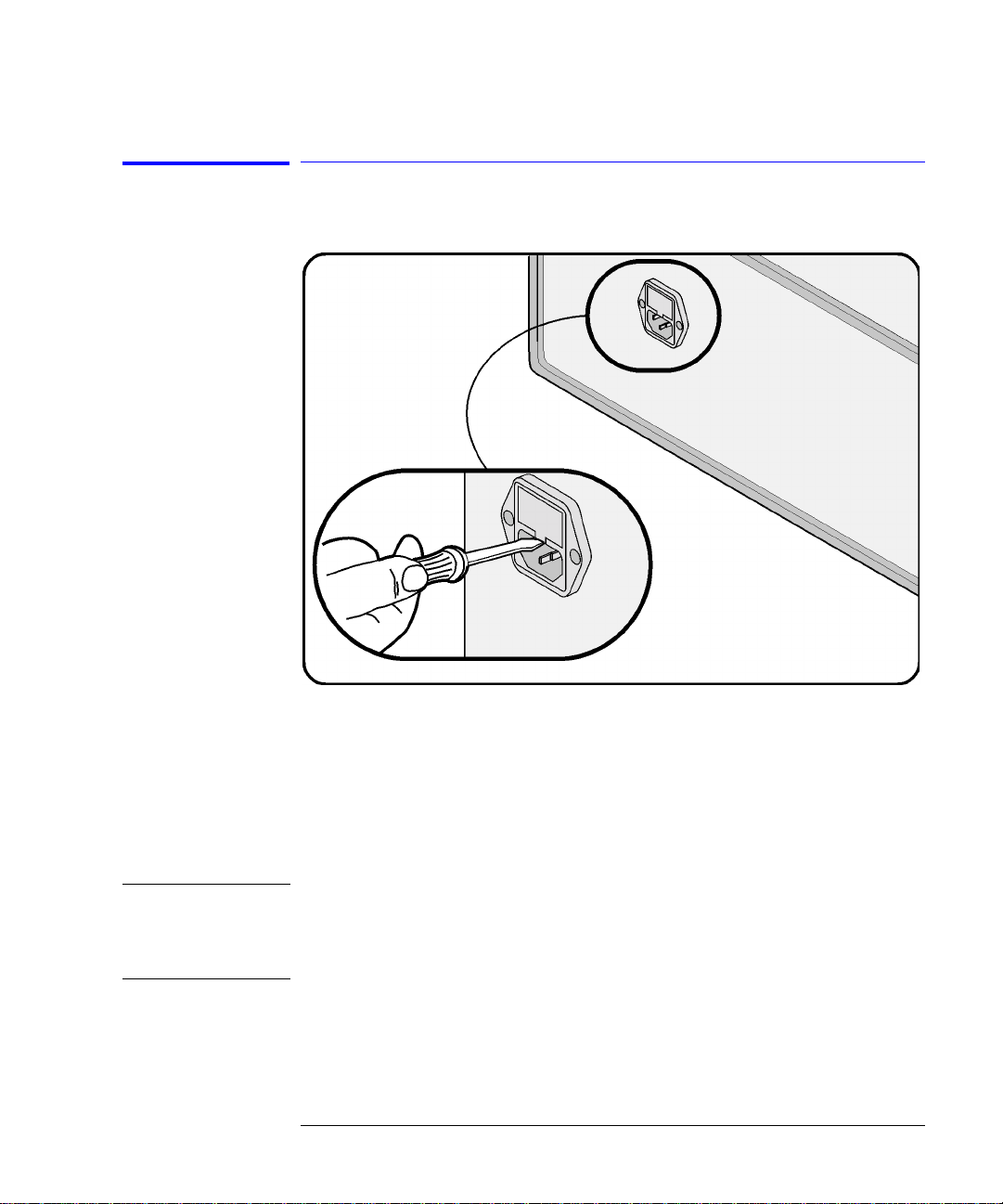
1 Locate the line-input connector on the instrument’s rear panel.
2 Disconnect the line-power cable if it is connected.
3 Use a small flat-blade screwdriver to pry open the fuse holder door.
4 The fuse is housed in a small container. Insert the tip of a screwdriver on the
side of the container and gently pull outward to remove the container. A spare
fuse is stored below the line fuse.
WARNI NG For continued protection against fire hazard, replace line fuse only
with same type and ratings (5
breaking capacity fuse). The use of other fuses or materials is
prohibited.
×20 mm, 1.6 A, 250 V time-delay, low
1-5
Page 14
Getting Started
Setting Up the Agilent 83434A
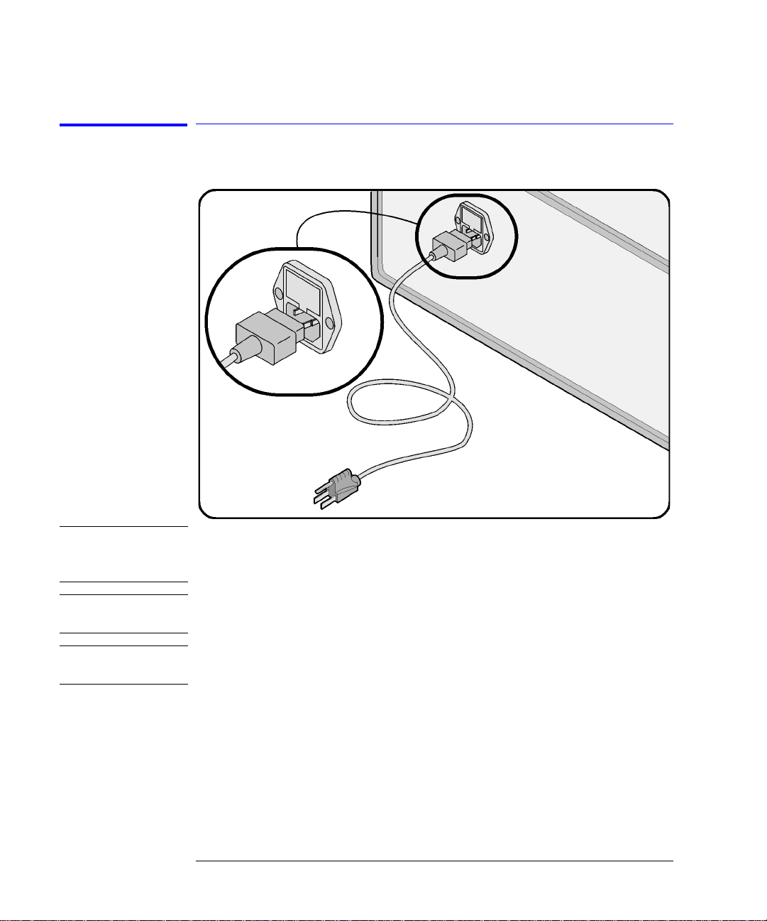
Step 3. Connect the Line-Power Cable
CAUTION Always use the three-prong AC power cord supplied with this instrument.
Failure to ensure adeq uate earth grounding by not us ing this cord may cause
instrument damage .
CAUTION Do not connect ac power until you have verified the line voltage is correct as
described in the follo wing paragraphs. Damage to the equipment could result.
CAUTION This instrument has autoranging line voltage input. Be sure the supply voltage
is within the specified range.
1-6
Page 15

Getting Started
Setting Up the Agilent83434A
1 Verify that the line power meets the requirements shown in the following table.
Line Power Requirements
Power 115 VAC: 50 Watts MAX
230 VAC: 50 Watts MAX
Voltage nominal: 115 VAC range:90–132 V
nominal:230 VACrange:98–254 V
Frequency nominal:50 Hz/60 Hzrange:47–63 Hz
2 Connect the lin e- po wer cord to the rear- pa nel connector of the instrument.
3 Connect the other end of the line-power cord to the power receptacle.
Various power cables are available to connect the Agilent 83434A to ac power
outlets unique to specific geographic areas. The cable appropriate for the area
to which the Agilent 83434A is originally shipped is included with the unit. You
can order additio na l ac power cables for us e in different geogra phic areas.
Refer to “Power Cords” on page 3-7.
1-7
Page 16
Getting Started
Setting Up the Agilent 83434A
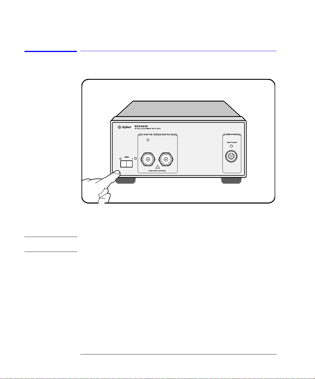
Step 4. Turn on the Agilent 83434A
With the power cable inserted into the line module, turn the lightwave
receiver on by pressing the line switch. The green light-emitting diode (LE D)
should light.
NOTE The front panel LINE switch disconnects the mains circuits from the mains supply after
the EMC filters and before other parts of the instrument.
If the Agilent 83434A fails to turn on properly, consider the following possibilities:
❒ Is the line fuse good?
❒ Does the line socket have power?
❒ Is it plugged into the proper ac power source?
If the instrument still fail s, return i t to Agilen t Technologies for repair. Refer to
“Instrument Service” on pag e 3-18
1-8
Page 17
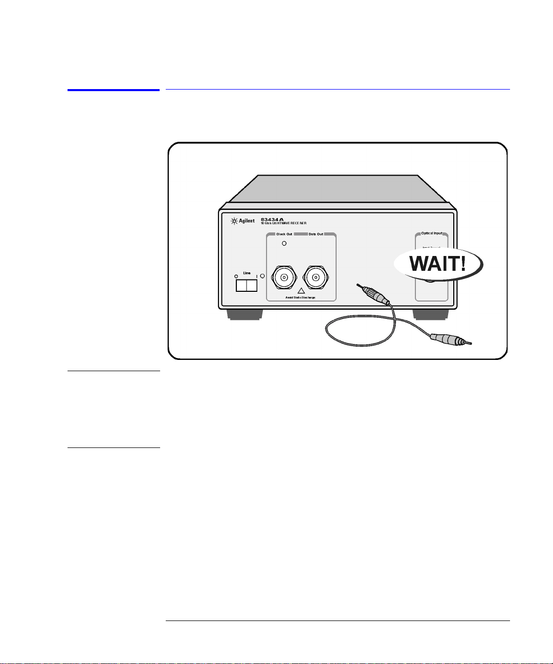
Step 5. Avoid costly repairs
Getting Started
Setting Up the Agilent83434A
CAUTION Fiber-optic connectors are easily damaged when connected to dirty or
damaged cables and accessories. The front-panel connectors of the
Agilent 83434A are no exception. When you use improper cleaning and
handling techniques , you risk expensive inst rum ent repairs, damaged cables,
and compromised measurements. Before you connect any fiber-optic cable to
the Agilent 834 34A , re fe r to “Fiber-Optic Connectors” on page 3-8.
1-9
Page 18

Getting Started
Setting Up the Agilent 83434A
Step 6. Learn more about our products
T o learn more about Agilent Technologies products, visit our website at
http://www.agilent.com.
If you wish to find out mor e a b o ut your new lightwave re c eiver, use the keyword “83434A” in your searc h.
1-10
Page 19

2
Front-Panel Features 2-2
Rear-Panel Features 2-3
Quick Confidence Check 2-4
Agilent 83434A Connection to a Bit-Err or-Ratio Test Set 2-6
BER Performance Verification 2-9
Using the Agilent 83434A
Page 20

Using the Agilent 83434A
Front-Panel Fe atures
Front-Panel Features
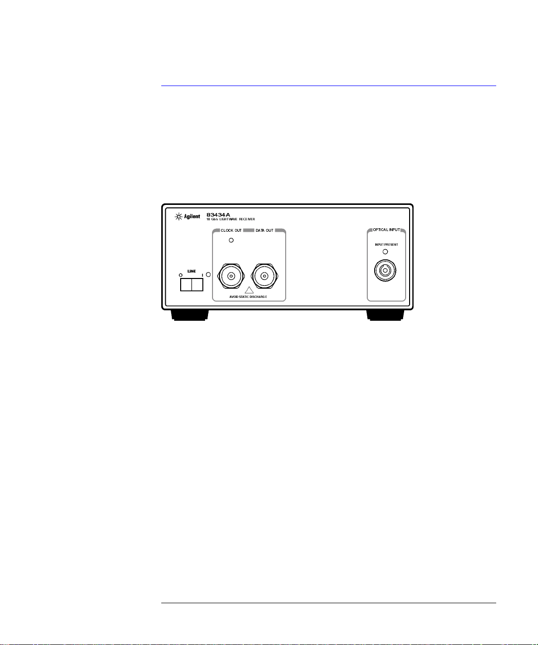
Figure 2-1. The Agilent 83434A front panel.
CLOCK OUT Outpu t is nomin a lly 9. 95328 GHz or 10.66423 GHz (option
106).
DATA OUT Provides an amplified, non-retimed signal corresponding to
the incoming data stream.
OPTICAL IN Maximum signal input is 0 dBm, damage level input is +7
dBm. This input accepts any of the Agilent 81000-series
connector interface adapters.
INPUT PRESENT Indicates the presence of suffic ient optical power.
2-2
Page 21

Rear-Panel Features
Using the Agilent 83434A
Rear-Panel Features
Figure 2-2. The Agilent 83434A rear panel.
2-3
Page 22

Using the Agilent 83434A
Quick Confidence Check
Quick Confidence Check
This procedure verifies the basic functionality of the lightwave receiver. The
following equipm ent is used:
• Agilent 83434A lightwave receiver
• Pattern generator
• Clock source
• Optical oscilloscope
• Optical source
Note
Before starting be sure to clean all connectors and optical interfaces using the procedures describe in “Fiber-Optic Connectors” on page 3-8.
1 Turn on the Agilent 83434A and let it warm up for 30 minutes.
2 Connect the output of the optical source (1300–1600 nm,
modulated at 9953.28 Mb/s or, for option 106, 10664.23 Mb/s) to the OPTICAL
INPUT of the Agile nt 83434A. The INPUT PRESENT LED should turn on.
3 Connect the CLOCK OUT and DATA OUT of the Agilent 83434A to the input of an
oscilloscope.
4 Check for clock and data waveforms.
2-4
≥ –16 dBm,
Page 23

Using the Agilent 83434A
Quick Confidence Check
If the verification check fails
If the lightwave receiver does not pass the veri fication check, you should
review the procedure being performed when the problem occurred. A few
minutes spent per forming some simple c hecks may save waiting for your
instrument to be repaired. Before calling Agilent Technologies or returning
the unit for service, ple a se make the following c hecks:
1 Is the line fuse good?
2 Does the line socket have power?
3 Is the unit plugged in to the proper ac power source?
4 Is the unit turned on ? Verify the green light-emitt ing diode (LED) next to the
line switch is on, indicating that the power supply is on.
5 If other equipment, cables, and connectors are being used with the lightwave
receiver, are the y co n nected properly and operat ing correctly?
6 Review the proced ure for the test being perfor med when the problem
appeared. Are al l the settings correct?
7 Are the connecto rs clean? Refer to “Cleaning Connectors” on page 3-15 for
more information about cleaning the connectors.
If the lightwave receiver still fails, you can:
Return the lightw a v e receiver to Agilent Technolo gies for repair. If the lightwave receiver is still under warranty or is covered by an Agilent Technologies
maintenance contract, it will be repaired under the terms of the warranty or
contract (the warranty is at the front of this manual). If the lightwave receiver
is no longer under warranty or is not covered by an Agilent Technologies
maintenance plan, Agilent Technologies will notify you of the cost of the repair
after examining the unit. Refer to “Instrument Service” on page 3-18 for more
information.
WARNI NG No operator serviceable parts inside. Refer servicing to qualified
personnel. To prevent electrical shock do not r emove covers.
2-5
Page 24

Using the Agilent 83434A
Agilent 83434A Connection t o a Bit - Error-Ratio Test Set
Agilent 83434A Connection to a Bit-Error-Ratio
Test Set
The following procedure describes how to connect the lightwave receiver to a
bit-error-ratio test set (BERT). Re fer to Figure 2-3 on page 2-7.
Note
Before starting, be sure to clean all connectors and optical interfaces using the procedures describe in“Fiber-Optic Connectors” on page 3-8.
2-6
Page 25
Using the Agilent 83434A
Agilent 83434A Connec tion to a Bit-Error-Ratio Test Set
Figure 2-3. Connecting the Agilent 83434A to a bit-error-ratio test system.
1 Turn the lightwave receiver on. Let it warm up for 30 minutes.
2 Turn on the BERT and the laser and le t them warm up according to their
specifications.
3 Perform any calibrations indicated in the documentation for the BERT.
4 Connect a cable from the CLOCK OUT connector on the lightwave receiver to the
clock input con nector of the BERT. A n a da p ter may be necessary.
5 Connect a cable from the DATA OUT connector on the lightwave receiver to the
data input connector on the BERT. An adapter may be necessary.
6 Clean the end of the OPTICAL INPUT glass fiber on the lightwave receiver and both
ends of the glass fiber cable. Refer to “Fiber-Optic Connectors” on page 3-8 for
instructions.
7 Connect the optical connector in te rfa ce to the OPTICAL INPUT. Notice the
connector interface has a small protrusion. This protrusion fits in the slot of the
OPTICAL INPUT connector.
8 Connect the cable to the receiver optical connector interface.
2-7
Page 26

Using the Agilent 83434A
Agilent 83434A Connection t o a Bit - Error-Ratio Test Set
9 Connect the laser source to the fiber optic cable.
2-8
Page 27

Using the Agilent 83434A
BER Performanc e Verification
BER Performance Verification
This procedure verifies BER performance of the of the Agilent 83434A lightwave receiver with the Agilent 83433A and 71612B.
The following e quipment is used:
• Agilent 83434A lightwave receiver
• Agilent 83433A lightwave transmitter
• Agilent 71612B Bit Error Rate Tester
• Optical attenuator
• Optical multimeter
Note
Before starting, be sure to clean all connectors and optical interfaces using the procedures describe in “Fiber-Optic Connectors” on page 3-8.
2-9
Page 28

Using the Agilent 83434A
BER Performance Verification
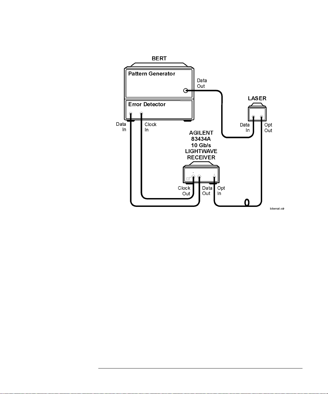
1 Connect the equipment as shown in Figure 2-4.
Figure 2-4. Setup to perform BER performance verification of the 83434A
2-10
Page 29

Using the Agilent 83434A
BER Performanc e Verification
2 Set the Agilent 71612B as follows:
CLOCK OUTPUT
SIG GEN FREQ. . . . . . . . . . . . . . . . . . . . . . . . . . . . . . . . . . . . . . . . . 9953.28 MHZ
SIG GEN FREQ (for 83434 option 106) . . . . . . . . . . . . . . . . . . . . . . . . 10664.23 MHZ
MENU
DATA OUTPUT
Ext AC COUPLED
DATA AMPLITUDE. . . . . . . . . . . . . . . . . . . . . . . . . . . . . . . . . . . . . . . . . . . 1.0 V
PATTERN
PRBS
31
–1
2
3 Disable WAVELENGTH ADJUST on the 83433A.
4 Turn on the 83433A laser.
5 Adjust the optical attenuator for a maximum of 0 dBm and a minimum of
–16 dbm at the output of the attenuator.
6 Set the Agilent 71612B as follows:
MENU
INPUT & EYE
0/1 THR CENTER
CLK/DATA ALIGN
MENU
GATING
RUN GA TING
7 Verify that the 71612B reports zero er rors.
2-11
Page 30

Using the Agilent 83434A
BER Performance Verification
2-12
Page 31

3
Accessories Supplie d 3-2
Options 3-3
Replacement Parts 3-4
Front-Panel Fiber-Optic Adapters 3-5
Power Cords 3 -7
Fiber-Optic Connectors 3-8
Choosing the Right Connector 3-8
Inspecting Connectors 3-11
Cleaning Connectors 3-15
Instrument Service 3-18
Preparing the Instrument for Shipping 3-19
Agilent TechnologiesService Offices 3-21
Reference
Page 32

Reference
Accessories Suppli ed
Accessories Supplied
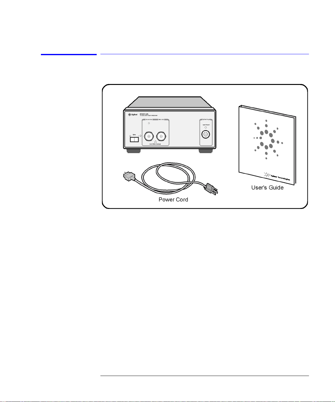
The Agilent 83434A lightwave receiver is shipped with:
• FC/PC connector in terface on the opt ical input of the lig htwave receive r unless
a different option was ordered. Refer to “Agilent 83434A Options” on page 3-3
for a complete list of the available connector interfaces.
• Agilent 83434A Lightwave Receiver User’s Guide, Agilent part number
83434-90005.
Available
seperately
The Fiber Optics Handbook, Agilent part number 5952- 9654, is an introduction and reference for fiber-optic measurements.
3-2
Page 33

Options
Table 3-1. Agilent 83434A Options
Option Description
Option 011 Diamond (HMS-10) connector interface on
the optical input of the lightwave receiver
Option 013 DIN connector interface on the optical
input of the lightwave receiver
Option 014 ST connector interface on the optical input
of the lightwave receiver
Reference
Options
Option 017 SC connector interface on the optical input
of the lightwave receiver
Option 106 For FEC signals, substitutes clock recovery
at 10.644 GHz
3-3
Page 34

Reference
Replacement P a r ts
Replacement Parts
Table3-2. Replacement Parts
Description AgilentPart Number
APC 3.5 F-to-F (connector saver ) 5061-5311
APC 3.5 50 ohm termination 1810-0118
FC/PC connector interface 81000FI
3-4
Page 35

Front-Panel Fiber-Optic Adapt ers
Front-Panel Fiber-Optic Adapters
Table 3-3. Front Panel Fiber-Optic Adaptes (1 of 2)
Front Panel
Fiber-Optic
Adapter
Description Agilent Part Number
Diamond HMS-10 81000AI
Reference
a
FC/PC
D4 81000GI
SC 81000KI
DIN 81000SI
ST 81000VI
Biconic 81000WI
Dust Covers
FC connector 1005-0594
Diamond HMS-10 connector 1005-0593
DIN connector 1005-0595
81000FI
3-5
Page 36

Reference
Front-Panel Fiber-Optic Adapters
Table 3-3. Front Panel Fiber-Optic Adaptes (2 of 2)
Front Panel
Fiber-Optic
Adapter
ST connector 1005-0596
SC connector 1005-0597
a. The FC/PC adapter is the standard adapter supplied with the instrument.
Description Agilent Part Number
3-6
Page 37

Power Cords
Reference
Power Cords
Plug Type Cable Part No. Plug Description
250V 8120-1351
8120-1703
250V 8120-1369
8120-0696
250V 8120-1689
8120-1692
8120-2857p
125V 8120-1378
8120-1521
8120-1992
250V 8120-2104
8120-2296
220V 8120-2956
8120-2957
Straight *BS136 3A
90°
Straight *NZSS198/ A S C
90°
Straight *CEE7-Y11
90°
Straight (Shiel de d)
Straight *NEMA5-15P
90°
Straight (Medical) UL544
Straight *SEV1011
1959-24507
Type 12 90°
Straight *DHCK1 07
90°
Length
(in/cm)
90/228
90/228
79/200
87/221
79/200
79/200
79/200
90/228
90/228
96/244
79/200
79/200
79/200
79/200
Color Country
Gray
Mint Gray
Gray
Mint Gray
Mint Gray
Mint Gray
Coco Brown
Jade Gray
Jade Gray
Black
Mint Gray
Mint Gray
Mint Gray
Mint Gray
United Kingdom,
Cyprus, Nigeria, Zim babwe, Singapore
Australia, New Zealand
East and West Europe,
Saudi Arabia, So.
Africa, India (unpolarized in many nations)
United States, Canada,
Mexico, Philippines,
Taiwan
Switzerland
Denmark
250V 8120-4211
8120-4600
100V 8120-4753
8120-4754
* Part number shown for plug is the industry identifier for the plug only. Number shown for cable is the Agilent
Technologies part number for the complete cable including the plug.
Straight SABS164
90°
Straight MITI
90°
79/200
79/200
90/230
90/230
Jade Gray Republic of South
Africa
India
Dark Gray Japan
3-7
Page 38

Reference
Fiber-Optic Co nnectors
Fiber-Optic Connectors
Today, advances in measurement capabilities make connectors and connection techniques more impor tant than ever. Damage to the connectors on calibration and verification devices, test ports, cables , and ot her device s can
degrade measurement accuracy and damage instruments. Replacing a damaged connector can cost thousands of dollars, not to mention lost time! This
expense can be avoided by observing the simple precautions presented in this
book. This book also contains a brief list of tips for caring for electrical connectors.
Choosing the Right Connector
A critical but often overlooke d fa c t or in making a good lightwave meas urement is the selection of the fiber-optic connector. The differences in connector types are mainly in the mechanic a l assembly that holds the ferrule in
position against another identical ferrule. Connectors also vary in the polish,
curve, and concentricity of the core within the cladd ing. Ma tin g one st yl e of
cable to another requires an adapter. Agilent Technologies offers adapters for
most instruments to allow testin g w ith many differen t c a bl es. Figure3-1 on
page 3-9 shows the b a sic components of a typical c onne c tors.
The system tole ranc e for reflection and in se rtion loss must be kno wn w h e n
selecting a connector from the wide variety of currently available connectors.
Some items to consider when selecting a connector are:
• How much insertion loss can be allowed?
• Will the connector need to make multiple connections? Some connectors are
better than others, and some are very poor for making repeated connections.
• What is the reflect ion tolerance? Can the syst em take reflection degrada tion?
• Is an instrument-grade connector with a precision core alignment required?
• Is repeatability tolerance for reflection and loss important? Do your specifica-
3-8
Page 39

Reference
Fiber-Optic Connectors
tions take repeatability uncertainty into account?
• Will a connector degrade the return loss too much, or will a fusion splice be required? For example, many DFB lasers cannot operate with reflections from
connectors. Often as much as 90 dB isolation is needed.
Figure 3-1. Basic components of a connector.
Over the last few ye a rs, the FC/PC style c o nne c tor has emerged as th e most
popular connector for fiber-optic applications. While not the highest performing connector, it represents a good compromise between performance, reliability, and cost. If properly maintained and cleaned, this connector can
withstand many repeated connections.
However, many instrument specifications require tighter tolerances than most
connectors, inc lu ding the FC/PC style, can delive r. These instruments cannot
tolerate connectors with the large non-co nce ntr ici ti e s of the fiber common
with ceramic style ferrules. When tighter alignme nt is required, Agilent
Technologies instru ments typical ly use a connector such as the Diamond
HMS-10, which has concentric tolerances within a few tenths of a micron. Agilent Technologies then use s a spec ial universal adapter, which allows other
cable types to mate with this precision connector. See Figure 3-2.
3-9
Page 40

Reference
Fiber-Optic Co nnectors
Figure 3-2. Universal adapters to Diamond HMS-10.
The HMS-10 enca se s the fiber within a soft nic kel silver (Cu/Ni/Z n) center
which is surrounded by a tough tun gs ten carbide casing, as shown in
Figure 3-3.
Figure 3-3. Cross-section of the Diamond HMS-10 connector.
The nickel silver allows an active centering process that permits the glass fiber
to be moved to the desired position. This process first stakes the soft nickel
silver to fix the fiber in a near-cen ter location, then uses a post-a c tive staking
to shift the fiber into the desired position within 0.2 µm. This process, plus t he
keyed axis, allows very precise core-to-core alignments. This connector is
found on most Agilent Technologies lightwave instruments.
3-10
Page 41

Reference
Fiber-Optic Connectors
The soft core, wh ile allowing precise cent ering, is also the chief lia bility of the
connector. The soft material is easily damaged. Care must be taken to minimize excessive scra tching and wear . Wh ile minor wear is not a problem if the
glass face is not af fected, scratches o r grit can cause the glas s fiber to move
out of alig nment. Also , if unke yed c onnect ors a re us ed, th e ni ckel silver can be
pushed onto the glass surface. Scratches, fiber movement, or glass contamination will caus e loss of s igna l and in creas ed re fl ect ion s, res u ltin g in p oor retu rn
loss.
Inspecting Connectors
Because fiber-optic connectors are susceptible to damage that is not immediately obvious to the naked eye, poor measurements result without the user
being aware. Microscopic examination and return loss measurem en ts are the
best way to ensure good measurements. Good cleaning practices can help
ensure that optim u m c onnector performa nce is maintained. With glass-toglass interfac e s, any degradatio n of a ferr ule or the end of the fibe r, any stray
particles, or finger oil can have a significant effect on connector performance.
Where many repeat connections are required, use of a connector saver or
patch cable is recomme nd ed.
Figure 3-4 shows the end of a cle an fiber-opt ic cable. The dark circle in th e
center of the micrograph is the fiber’s 125
the light. The surrounding area is the soft nickel-silver ferrule. Figure 3-5
shows a dirty fiber end from neglect or perhaps improper cleaning. Material is
smeared and gr ou nd i n to t he end o f t he f ib er ca usi ng li ght sc att eri ng an d poo r
reflection. Not only is the precision polish lost, but this action can grind off the
glass face and destroy the connector.
Figure 3-6 shows physical damage to the glass fibe r end caused by either
repeated connections made without removing loose particles or using
improper cleaning tools. When severe, the damage of one connector end can
be transferred to anothe r good connector endface that comes in co ntact with
the damaged one. Periodic checks of fiber ends, and replacing connecting
cables after many connections is a wise practice.
The cure for these problems is disciplined connector care as described in the
following lis t an d in “Cleaning Connectors” on page 3-15.
µm core and cladding which carries
3-11
Page 42

Reference
Fiber-Optic Co nnectors
Use the following guidelines to achieve the best poss ible performance when
making measurements on a fiber-optic system:
• Never use metal or sharp objects to clean a connector and never scrape the
connector.
• Avoid matchi ng gel and oils.
Figure 3-4. Clean, problem-free fiber end and ferr ul e.
Figure 3-5. Dirty fiber end and ferrule from poor cleaning.
3-12
Page 43

Reference
Fiber-Optic Connectors
Figure 3-6. Damage from improper cleaning.
While these often work well on first insertion, they are great dirt magnets. The
oil or gel grabs and holds grit that is then ground into the end of the fiber.
Also, some early gels were designed for use with the FC, non-contacting connectors, using small glass spheres. When used with contacting connectors,
these glass balls can scratch and pit the fiber. If an index matching gel or oil
must be used, apply it to a freshly cleaned connector, make the measurement,
and then immediately clean it off. Never use a gel for longer-term connections
and never use it to improve a damaged connector. The gel can mask the extent
of damage and continued use of a damaged fib er can trans fer damage to the
instrument.
• When insertin g a fiber-optic cable into a connector, gently insert it in as
straight a line as possible. Tipping and inserting at an angle can scrape material
off the inside of the connector or even break the inside sleeve of connectors
made with ceramic material.
• When inserting a fiber-optic connector into a connector, make sure that the fiber end does not touch the ou ts ide of the mating connector or adapte r.
• Avoid over tightening connections.
Unlike common electrical connections, tighter is not better. The purpos e of
the connector is to bring two fiber ends together. Once they touch, tightening
only causes a greate r f or c e to be a pp lied to the delicate fibers . With connectors that have a convex fiber end, the end can be pushed off-axis resulting in
misalignmen t a nd excessive return loss. Many measure ments are actuall y
improved by backing off the co nnector pressu re . Also, if a piece of grit does
happen to get by the cleaning procedure, the tighter connection is more likely
to damage the glass. Tighten the connectors just until the two fibers touch.
3-13
Page 44

Reference
Fiber-Optic Co nnectors
• Keep connectors covered when not in use.
• Use fusion splices on the more permanent critical nodes. Choose the best con-
nector possible. Replace connecting cables regularly. Frequently measure the
return loss of the connector to check for degradation, and clean every connector, every time.
All connectors should be treated like the high-quality lens of a good camera.
The weak link in instrument and syste m reliability is often the inappropriate
use and care of the connector. Because current connectors are so easy to use,
there tends to be reduced vigilance in connector care and cleaning. It takes
only one missed cle a ning for a piece of grit to perm a nently damage the gl a ss
and ruin the conne c to r.
Measuring insertion loss and return loss
Consistent measureme nts with your lightwave equipment are a good indication that you have good connections. Since return loss and in s ertion loss are
key factors in determining optical connector performance they can be used to
determine connector degradation. A smooth, polished fiber end should produce a good return-loss measurement. The quality of the pol ish establishes
the difference bet w een the “PC” (physical contact) and the “Super P C ” connectors. Most connectors today are physical contact which make glass-to-glass
connections, therefore it is critical that the area around the glass core be clean
and free of scratches. Although the major area of a connector, excluding the
glass, may show sc ratc hes and wear, if the glass has maintai n e d its polished
smoothness, the connector can stil l provide a good low level return loss connection.
If you test your cables and accessories for insertion loss and re turn loss upon
receipt, and retain the measured data for comparison, you will be able to tell in
the future if any degradation has occurred. Ty pical values are less than 0.5 dB
of loss, and somet im es as little as 0.1 dB of lo ss wi th high performance co nnectors. Return loss is a measure of reflection: the less reflection the better
(the larger the return loss, the smaller the reflection). The best physically
contacting connectors have return losses bette r than 50 dB, althoug h 30 to
40 dB is more common.
3-14
Page 45

Reference
Fiber-Optic Connectors
Visual inspection of fiber ends
Visual ins pe cti on of fi ber en ds c an be hel pfu l. Cont amin at ion o r im perf ect ion s
on the cable end fa ce c a n be detected as well as cr a c k s or chips in the fiber
itself. Use a microscope (100X to 200X magni fi cation) to inspect the entire
end face for contam ina tion, raised meta l, or dents in the metal a s well as any
other imperfections. Inspect the fiber for cr a c k s a nd ch ip s. Visible imperfec tions not touching the fibe r core may not affect performance (unl es s the
imperfections keep the fibers from contacting).
WARNI NG Always remove both ends of fiber-optic cables from any instrument,
system, or device before visually inspecting the fiber ends. Disable all
optical sources before disconnecting fiber-optic cables. Failure to do
so may result in permanent injury to your eyes.
Cleaning Connectors
The procedures in this section provide the proper steps for cleaning fiberoptic cables and Agilent Technologies universal adapters. The initial cleaning,
using the alcohol as a solvent, gently removes any grit and oil. If a caked-on
layer of material is still present, (this can happen if the beryllium-copper sides
of the ferrule retainer get scraped and deposited on the end of the fiber during
insertion of the cable), a second cleaning should be performed. It is not
uncommon for a cable or connector to req uire more than one cleaning.
CAUTION Agilent Technologies strongly recommends that index matching compounds
not be applied to their instruments and accessories. Some compounds, such as
gels, may be difficult to remove and can contain damaging particulates. If you
think the use of such compounds is necessary, refer to the compound
manufacturer for infor mation on application and cleani ng procedures.
Table 3-4. Cleaning Accessories
Item AgilentPart Number
Any commercially available denatured alcohol —
Cotton swabs 8520-0023
Small foam swabs 9300-1223
Compressed dust remover (non-resi due) 8500-5262
3-15
Page 46

Reference
Fiber-Optic Co nnectors
Table 3-5. Dust Caps Provided with Lightwave Instruments
Item AgilentPart Number
Laser shutter cap 08145-64521
FC/PC dust cap 08154-44102
Biconic dust cap 08154-44105
DIN dust cap 5040-9364
HMS10/dust cap 5040-9361
ST dust cap 5040-9366
To clean a non-lensed connector
CAUTION Do not use any t ype of foam swab to clean optical fiber ends. Foam swabs can
leave filmy deposits on fiber e nds that can degrade performance.
1 Apply pure isopropyl alcohol to a clean lint-free cotton swab or lens paper.
Cotton swabs can be used as long as no cotton fibers remain on the fiber end
after cleaning.
2 Clean the ferrules and other parts of the connector while avoi ding the end of
the fiber.
3 Apply isopropyl alcohol to a new clean lint-free cotton swab or lens paper.
4 Clean the fiber end with the swab or lens paper.
Do not scrub during this initial cleaning because grit ca n be caught in the
swab and become a gouging element.
5 Immediately dry the fiber end with a clean, dry, lint-free cotton swab or lens
paper.
6 Blow across the connector end face from a distance of 6 to 8 inches using
filtered, dry, compressed air. Aim the compressed air at a shallow angle to the
fiber end face.
Nitrogen gas or com pressed dust remo ver can also be used.
3-16
Page 47

Reference
Fiber-Optic Connectors
CAUTION Do not shake, tip, or invert compressed air canisters, because this releases
particles in the can into the air. Refer to instructions provided on the
compressed air canister.
7 As soon as the connec tor is dry, connect or cover it fo r later use.
If the performance, after the initial cleaning, seems poor try cleaning the connector again. Often a second cleaning will restore proper performance. The
second cleaning should be more arduous with a scrubbing action.
To clean an adapter
The fiber-optic input and output connectors on many Agilent Technologies
instruments employ a universal adapter such as those shown in the following
picture. These adapters allow you to connect the instrument to different types
of fiber-optic cables.
Figure 3-7. Universal adapters.
1 Apply isopropyl alcohol to a clean foam swab.
Cotton swabs can be used as long as no cotton fibers remain after cleaning. The
foam swabs listed in this section’s introducti on are small enough to fit into
adapters.
Although foam swabs can lea ve filmy depo sits, these d eposits are very thin, an d
the risk of other conta m ination buildup on the inside of adapters greatly outweighs the risk of contamination by foam swabs.
2 Clean the adapter with the foam swab.
3 Dry the inside of th e ad a pter with a clean, dry, foam swab.
4 Blow through the adapter using filtered, dry, compressed air.
Nitrogen gas or compressed dust remover can also be used. Do not shake, tip,
or invert compressed air canisters, because this releases particles in the can
into the air. Refer to instructions provided on the compressed air canister.
3-17
Page 48

Reference
Instrument Service
Instrument Service
Before returnin g your instrument fo r servicing, you may w a nt to re fer to the
Agilent website, www.agilent.com (quick search “83434A”). It contains application notes and frequently asked questions (FAQ) specific to the 83434A that
may answer many of your questions.
If you continue to experience difficulties, please call the Agilent Technologies
Instrument Supp o rt Center to initiate servi c e before returning your instrument to a service office. This ensures that the repair (or calibration) can be
properly tracked and that your instrument will be returned to you as quickly
as possible. Call this number regardless of where you are located.
Agilent Technologies Instrument Support Cent er . . . . . . . . . .1(800) 403-0801
After you have initiated service by callin g the Agil ent Techn ologies I nstrument
Support Center, contact your local service office. For a list of offices, refer to
“Agilent Technologies Service Offices” on page 3-21.
If the instrument is still unde r warranty or is covered by an Agilent
Technologies maintenance contract, it will be repaired under the terms of the
warranty or contract (the warranty is at the front of this manual). If the
instrument is no longer under warranty o r is not covered by an Agil ent
Technologies maintenance p lan, Agilent Techn o logies will notify you of the
cost of the repair after examining the unit.
3-18
Page 49

Reference
Instrument Service
Preparing the Instrument for Shipping
1 Write a complete description of the failure and attach it to the instrument.
Include any specific performance details related to the problem. The following
information should be returned with the instrument.
• Type of ser v ic e required.
• Date instrument was returned for repair.
• Description of the problem:
• Whether problem is constant or intermittent.
• Whether instrument is temperature-sensitive.
• Whether in strument is vibration-sensitive.
• Instrument settings required to reproduce the problem.
• Performance data.
• Company name and return address.
• Name and phone number of technical contact person.
• Model number of returned instrument.
• Full serial number of returned instrument.
• List of any accessories returned with instrument.
2 Cover all front or rear-panel connectors that were originally covered when you
first received the instrument.
CAUTION Cover electrical connectors to protect sensitive components from electrostatic
damage. Cover opti cal connectors to protect them from da mage due to physical
contact or dust.
CAUTION Instrument damage can result from usin g p ac k aging materials other than the
original materials. Never use styrene pellets as packaging material. They do not
adequately cus hion the instrument o r pre v ent it from shiftin g in the carton.
They may also cause instrument damage by generating static electricity.
3 Pack the instrument in the original shipping containers. Original materials are
available through any Agilent Technologies office. Or, use the following
guidelines:
• Wrap the instrument in antistatic plastic to reduce the possibility of damage
caused by electrostatic discharge.
• For instruments weighing less than 54 kg (120 lb), use a double-walled, cor-
3-19
Page 50

Reference
Instrument Service
rugated cardboard carton of 159 kg (350 lb) test strength.
• The carton must be large enough to allow approximately 7 cm (3 inches) on
all sides of the instrument for packing material, and strong enough to accommodate the weight of the instrument.
• Surround the equipment with approximately 7 cm (3 inches) of packing material, to protect the instrument and prevent it from moving in the carton. If
packing foam is not available, the best alternative is S.D-240 Air Cap™ from
Sealed Air Corporation (Commerce, Califor nia 900 01). Air Cap look s like a
plastic sheet filled with air bubbl es . U se the pink (antistati c ) Air Cap™ to
reduce static electricity. Wrapping the instrument several times in this material will protect the instrument and prevent it from moving in the carton.
4 Seal the carton with strong ny lon adhesive tape.
5 Mark the carton “FRAGILE, HANDLE WITH CARE”.
6 Retain copies of all shipping papers.
3-20
Page 51

Reference
Instrument Service
Agilent TechnologiesService Offices
Before returning an instrument fo r serv ice, call the Agilen t Technologies Instrument
Support Center at 1 (800) 403-0801. If you continue to experience difficulties,
please call one of the numbers listed below.
Agilent Technologies Service Numbers (1 of 2)
Austria 01/25125-7171
Belgium 32-2-778.37.71
Brazil (11) 7297-8600
China 86 10 6261 3819
Denmark 45 99 12 88
Dominican Republic (809) 563-6350
Finland 358-10-855-2360
France 01.69.82.66.66
Germany 0180/524-6330
India 080-34 35788
Italy +39 02 9212 2701
Ireland 01 615 8222
Japan (81)-426-56-7832
Korea 82/2-3770-0400
Mexico (5) 258-4826
Netherlands 020-547 6463
Norway +47 22 73 57 59
Puerto Rico (800) 403-0801
Russia +7-095-797-3930
Spain (34/91) 631 1213
3-21
Page 52

Reference
Instrument Service
Agilent Technologies Service Numbers (2 of 2)
Sweden 08-5064 8700
Switzerland (0 1) 73 5 7200
Taiwan (886 2) 2-712 -0404
United Kingdom 01 344 366666
United States and Canada (80 0) 403-0801
3-22
Page 53

4
Agilent 83434A Specifications and Characteristics 4-3
Regulatory Information 4-6
Declaration of Conformity 4-7
Specifications and Regulatory Information
Page 54

Specifications and Regulatory Information
Specifications and Regulatory Information
Specifications and Regulatory Information
This chapter lists specification and characteristics of the instrument. The distinction between these terms is described as follows:
• Specifications describe warranted performance over the tempe rature range
°C to +45°C and relative humidity <95% non-condensing (unless otherwise
0
noted). All specifications apply a fter the temperat ure o f the instrument is sta bilized after 30 minute s of continuous operation.
• Characteristics provide useful information by giving func tional, but nonwarrant -
ed, performance parame ters. Characteristics are printed in this typeface.
Calibration cycle
This instrument requires periodic verification of performance. The instrument
should have a complete verification of specifications at least once every two
years.
4-2
Page 55

Specifications and Regulat ory Information
Agilent83434A Specifications and Characteristics
Agilent 83434A Specifications and
Characteristics
OPERATING SPECIFICATIONS
Optical Input
Wavelength
Optical input power
a,b,c,d
Return loss
“Loss of optical input” alarm
threshold
1300 to 1600 nm
–16 to 0 dBm
28 dB minimum
–25 to –20 dBm
Maximum Safe Input Level
Optical input power
e
Data Output
Amplitude
Lower 3 dB frequency
Upper 3 dB frequency
Return loss
f,g
h
h,
j
Impedance
+7 dBm maximum
0.5 to 1.5 V pk-pk
0.10 MHz
i
6.5 GHz
9.5 dB minimum
50
Ω
4-3
Page 56

Specifications and Regulatory Information
Agilent 83434A Specifications and Characteristics
Recovered Clock Output
Amplitude
Frequency
Frequency (opt. 106)
Duty cycle
Clock to data alignment
3 dB bandwidth
Jitter generation
Return loss
Impedance
h
k
0.5 to 1. 5 V pk-pk
9953.26 to 9953.30 MHz; 9953.28 nominal
10664.03 to 10664.43 MHz; 10664.23 nominal
45/55% maximum; 50/50% nominal
l
k
g,
m
n
±25.12 ps maximum
8 to 12 MHz; 10 MHz nominal
2 ps rms maximum
12 dB minimum
50
Ω
GENERAL SPECIFICATIONS
Temperat ure Range
Operating 0°C to +45°C
Storage –40°C to +70°C
EMI Compatibility Conducted and radiated emissions meet the
requirements of CISPR Pub lication 11, Class A and
immunity in compliance with IEC 61326-1
Power Requirements 100/120/220/240 V (±10%), 47 to 63 Hz
Weight (character istic) 3.4 kg (7.6 lb)
Dimensions 102mm (4 in) height, 216 mm (8.5 in) widt h, 444
mm (17.5 in) depth (Agilent System II, half-width
case)
FRONT-PANEL INPU T / OUTPUT
Optical Input Connector
Diamond HMS-10/HP
o
Data Output Connector APC-3.5 male
Recovered Clock Output Co nnect or APC-3.5 male
a. Better than 1x10
or b)100 consecutive “ones” or “zeros” on a 2
b. Source extinction ratio
c. Applies over the temperature range 25
d. Tested with FC/PC adapter.
e. 1310 or 1550 nm.
f. Non-inverting, non-retimed linear output with AGC stabilization.
g. For PRBS up to and including 2
h. AC coupled
i. Measured with a swept network analyzer at –8 dBm optical input with fixed AGC control in Tx and Rx.
j. 0.01 to 10,700 MHz.
k. Type A resonator based clock recovery.
-10
BER when tested wi th the Agil ent 71612 B using eithe r of two pat terns: a) 231–1 PRBS,
31
–1 PRBS.
≥ 8.2 dB measured within ±10% of eye center
°C ±10°C.
31
–1.
4-4
Page 57

Specifications and Regulat ory Information
Agilent83434A Specifications and Characteristics
l. Falling clock edge to data transition measured wi th 2 31–1 PRBS.
m. Integrated phase noise measur em ent method.
n. 9,940 to 9,960 MHz standard, 10624 to 10684 MHz (option 106).
o. Standard instrument has FC/PC adapters. Other adapters available as options.
4-5
Page 58

Specifications and Regulatory Information
Regulatory Information
Regulatory Information
This product i s designed for use in INSTALLATION CATEGORY II and POLLUTION DEGREE 2, per IEC 61010-1 and 664 respectively.
Notice for
Germany: Noise
Declaration
This is to declare that this instrument is in conformance with the German Regulation on Noise Declaration for Machines (Laermangabe nach der Maschinenlaermrerordnung –3.GSGV Deutschland).
Acoustic Noise Emission Geraeuschemission
LpA < 70 dB
Operator position
Normal position
per ISO 7779
LpA < 70 dB
am Arbeitsplatz
normaler Betrieb
nach DIN 45635 t.19
4-6
Page 59
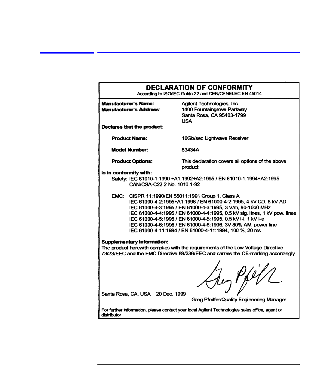
Declaration of Conformity
Specifications and Regulat ory Information
Regulatory Information
4-7
Page 60

Specifications and Regulatory Information
Regulatory Information
4-8
Page 61

Index
A
ac power cables, 1-7
accessories, 3-2
adapters
fiber optic, 3-5
Agilent
sales and service offices, 3-21
B
BER performance
verifying, 2-9
bit-error-ratio test set, 2-6
C
cabinet, cleaning, i-iii
calibration
cycle, 4-2
care
of cabinet, i-iii
care of fiber optics, 1-9
characteristics, 4-3
checking the fuse, 1-5
classification
product, i-iii
cleaning
adapters, 3-17
cabinet, i-iii
fiber-optic connections, 3-8, 3-16
non-lensed connectors, 3-16
clock out connector, 2-2
compressed dust remover, 3-15
connector
care, 3-8
connector interface
front-panel, 3-2
cotton swabs, 3-15
care of, 1-9
cleaning connections, 3-8
connectors, covering, 3-19
fiber optics handbook, 3-2
foam swabs, 3-15
front panel
adapters, 3-5
connector interface, 3-2
features, 2-2
fuse
values, i-iii
I
initial inspection , 1-3
input
connector, 3-8
input present indicator, 2-2
installing, 1-2
L
line fuse, 1-5
line fuse, safety, i-iii, 1-5
line-power
cable, 1-6
cables, 3-7
input connector, 1-5
requirements, 1-7
M
maintenance contract, 2-5
measurement
accuracy, i-iv
N
noise declaration, 4-6
D
declaration of conformity, 4-7
dust caps, 3-16
F
fiber optics
adapters, 3-5
O
optical in connector, 2-2
P
packaging for shipment, 3-19
parts, 3-4
Index-1
Page 62

Index
power cable requirements, 1-6
R
rear panel features, 2-3
regulatory
duration, 4-2
information, 4-6
repair options, 2-5
replacement, 3-4
replacement parts, 3-4
returning for service, 3-18
S
safety, i-iii
laser classification, i-iii
line fuse, i-iii, 1-5
sales and service offices, 3-21
serial numbers, 1-4
service, 3-18
options, 2-5
returning for, 3-18
shipping
procedure, 3-19
spare fuse, 1-5
specifications, 4-3
definition of terms, 4-2
swabs, 3-15
T
turning on the lightwave receiver, 1-8
V
verification test
failing, 2-5
verifying BER performance, 2-9
W
warranty, 2-5
Index-2
 Loading...