

Page 1

Agilent 82350B
PCI GPIB
Interface
Installation and
Configuration
Guide
Agilent Technologies
Page 2

Notices
© Agilent Technologies, Inc. 2002–2013
No part of this manual may be reproduced
in any form or by any means (including
electronic storage and retrieval or
translation into a foreign language)
without prior agreement and written
consent from Agilent Technologies, Inc. as
governed by United States and
international copyright laws.
Manual Part Number
82350-90004
Edition
Eleventh Edition, March 19, 2013
Printed in Malaysia
Agilent Technologies, Inc.
5301 Stevens Creek Blvd.
Santa Clara, CA 95052 USA
Trademark Acknowledgement
Microsoft, Windows, and Windows Vista
are trademarks or registered trademarks of
Microsoft Corporation in the United States
and/or other countries.
Warra nty
The material contained in this document
is provided “as is,” and is subject to
being changed, without notice, in future
editions. Further, to the maximum extent
permitted by applicable law, Agilent disclaims all warranties, either express or
implied, with regard to this manual and
any information contained herein, including but not limited to the implied warranties of merchantability and fitness for a
particular purpose. Agilent shall not be
liable for errors or for incidental or consequential damages in connection with
the furnishing, use, or performance of this
document or of any information contained
herein. Should Agilent and the user have
a separate written agreement with warranty terms covering the material in this
document that conflict with these terms,
the warranty terms in the separate agreement shall control.
Technology Licenses
The hardware and/or software described
in this document are furnished under a
license and may be used or copied only in
accordance with the terms of such license.
Restricted Rights Legend
U.S. Government Restricted Rights. Software and technical data rights granted to
the federal government include only those
rights customarily provided to end user
customers. Agilent provides this customary commercial license in Software and
technical data pursuant to FAR 12.211
(Technical Data) and 12.212 (Computer
Software) and, for the Department of
Defense, DFARS 252.227-7015 (Technical
Data - Commercial Items) and DFARS
227.7202-3 (Rights in Commercial Computer Software or Computer Software Documentation).
ii
Page 3

Safety Notices
CAUTIONCAUTION
WARNING
A CAUTION notice denotes a hazard. It calls attention to an
operating procedure, practice, or the like that, if not correctly
performed or adhered to, could result in damage to the product
or loss of important data. Do not proceed beyond a CAUTION
notice until the indicated conditions are fully understood
and met.
A WARNING notice denotes a hazard. It calls attention to
an operating procedure, practice, or the like that, if not
correctly performed or adhered to, could result in
personal injury or death. Do not proceed beyond a
WARNING notice until the indicated conditions are fully
understood and met.
iii
Page 4
Safety Symbols
The following symbol on the instrument and in the
documentation indicates precautions that must be taken to
maintain safe operation of the instrument
.
Direct current
Alternating current
Both direct and alternating current
Three-phase alternating current
Earth (ground) terminal
Protective conductor terminal
Frame or chassis terminal
Equipotentiality
Equipment protected throughout by double insulation
or reinforced insulation
Caution, risk of electric shock
iv
Page 5

Caution, risk of danger (refer to this manual for specific
Warning or Caution information.
Caution, hot surface
v
Page 6

General Safety Information
CAUTIONCAUTION
WARNING
• Use the device with the cables provided.
• Repair or service that is not covered in this manual should
only be performed by qualified personnels.
• Do not use the device if it appears damaged or
defective.
• Observe all markings on the device before connecting
any wiring to the device.
• Do no operate the device in the presence of flammable
gases or fumes.
• Do no install substitute parts or perform any
unauthorized modification to the device.
vi
Page 7

Environment Conditions
CAUTIONCAUTION
This instrument is designed for indoor use in areas with low
condensation. The table below shows the general environment
requirements.
Environment Conditions Requirements
Operating environment 0 °C to +55 °C
Operating humidity Up to 90% at 40 °C non-condensing
Storage environment –40 °C to +70 °C
Storage humidity Up to 90% at 65 °C non-condensing
The Agilent 82350B PCI GPIB Interface complies with the
following safety and EMC requirements:
IEC 61326-1 Group 1, Class A
IEC 61010-1
vii
Page 8
Regulatory Markings
The CE mark is a registered trademark of the
European Community. The CE mark shows that the
product complies with all the relevant European
Legal Directives.
ICES/NMB-001 indicates that this ISM device
complies with Canadian ICES-001.
The CSA mark is a registered trademark of the
Canadian Standards Association. A CSA mark with
the indicators “C” and “US” means that the product
is certified for both the U.S. and Canadian markets,
to the applicable American and Canadian
standards.
The C-tick mark is a registered trademark of the
Spectrum Management Agency of Australia. This
signifies compliance with the Australia EMC
Framework regulations under the terms of the
Radio Communication Act of 1992.
This product complies with the WEEE Directive
(2002/96/EC) marking requirement. The affixed
product label indicates that you must not discard
this electrical/electronic product in domestic
household waste.
viii
Page 9
Waste Electrical and Electronic Equipment
(WEEE) Directive 2002/96/EC
This instrument complies with the WEEE Directive
(2002/96/EC) marking requirement. This affixed product label
indicates that you must not discard this electrical/electronic
product in domestic household waste.
Product Category:
With reference to the equipment types in the WEEE directive
Annex 1, this instrument is classified as a “Monitoring and
Control Instrument” product.
The affixed product label is shown as below:
Do not dispose in domestic household waste
To return this unwanted instrument, contact your nearest
Agilent office, or visit:
www.agilent.com/environment/product
for more information.
ix
Page 10

Declaration of Conformity (DoC)
NOTE
The Declaration of Conformity (DoC) for this instrument is
available on the Agilent Web site. You can search the DoC by
its product model or description at the Web address below.
http://regulations.corporate.agilent.com/DoC/search.htm
If you are unable to search for the respective DoC, please
contact your local Agilent representative.
x
Page 11

Table of Contents
1 Installing and Configuring the 82350B
Getting Started 2
Step 1: Checking Your Shipment 4
Step 2: Installing Agilent IO Libraries Suite 5
Step 3: Connecting Your Instruments 7
Installing the 82350B in your PC 7
Connecting instruments to the 82350B 10
Step 4: Configuring the 82350B 13
Installing configuration files 13
Configuring the 82350B interface 14
Step 5: Communicating with your instruments 17
Verifying instrument communication 17
Programming your instruments (optional) 18
Set 82350B Read/Write Performance Mode 21
2 Troubleshooting Guidelines
Troubleshooting Overview 24
82350B Hardware Checks 25
Check cables/connections/power 25
Check Device Manager 26
82350B Software Checks 26
Check BIOS/Interrupts Settings 26
Agilent IO Libraries Suite Checks 28
Check IO Libraries Suite installation 28
Check IO Control operation 29
Install IO Libraries Suite (if 82350B was installed first) 30
3 82350B Specifications and Information
General Requirements 32
xi
Page 12

General Characteristics 33
Accessing an Electronic Copy of this Guide 34
Contacting Agilent 35
xii
Page 13

Agilent 82350B PCI GPIB Interface
Installation and Configuration Guide
1 Installing and Configuring the 82350B
This chapter shows a suggested five-step process to install
and configure the 82350B, and how to use the Agilent IO
Libraries Suite to configure the card in PCs with
Windows® XP, Windows Vista®, Windows 7, Windows 8, or
Windows Server 2008 R2 operating systems.
Agilent Technologies
1
Page 14
1 Installing and Configuring the 82350B
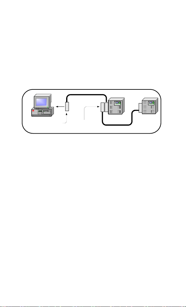
PC
Instrument
GPIB Cable
Connect to 82350B GPIB
Interface Card installed in PC.
Instrument
Connect to GPIB
port on instrument.
Getting Started
In this guide, an 82350B GPIB Interface System is defined as a
system in which GPIB instruments are connected via GPIB
cables to an 82350B PCI GPIB Interface Card that is installed in
a Windows PC. Figure 1-1 shows a typical system.
Figure 1-1 Typical configuration system
Use the following sequence of steps as a guide as you set up
your GPIB system. See the associated steps if you need more
details. See Chapter 2, “Troubleshooting Overview“ if you need
additional information on setting up the 82350B or
GPIB instruments.
2 82350B Installation and Configuration Guide
Page 15
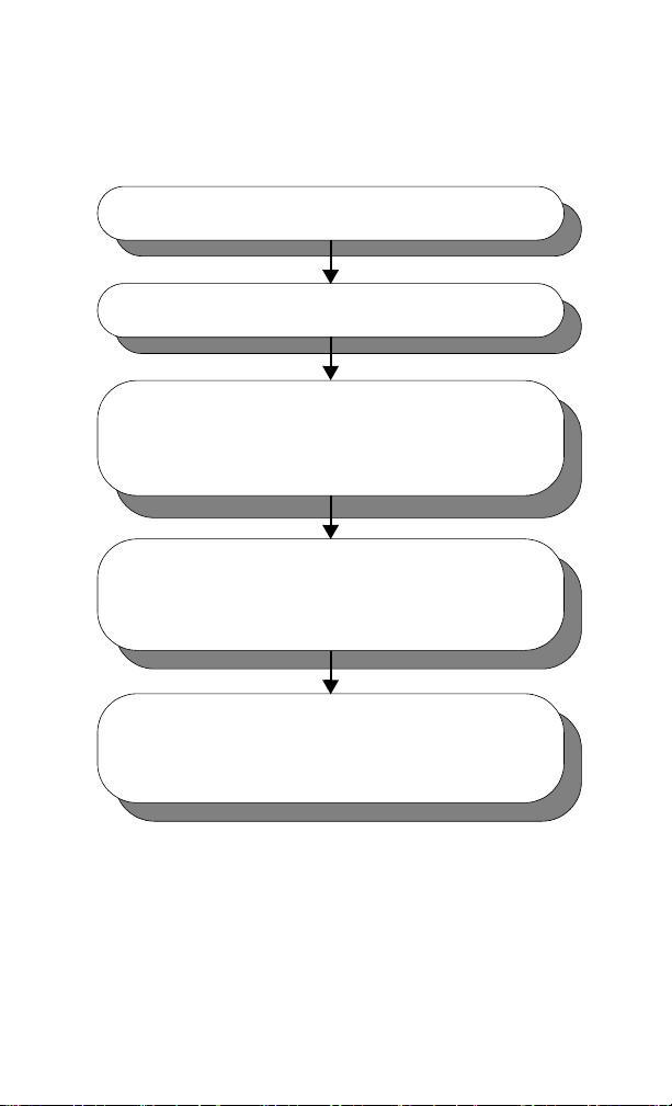
Installing and Configuring the 82350B 1
Step 1: Checking Your Shipment
Step 2: Installing Agilent IO Libraries Suite
Step 3: Connecting Your Instruments
• Installing the 82350B in your PC
• Connecting instruments to the 82350B
Step 4: Configuring the 82350B
• Installing configuration files
• Configuring the 82350B interface
Step 5: Communicating with Instruments
• Verifying instrument communication
• Programming your instruments (optional)
Figure 1-2 Steps to Install and Configure the 82350B Interface
82350B Installation and Configuration Guide 3
Page 16
1 Installing and Configuring the 82350B
CAUTIONCAUTION
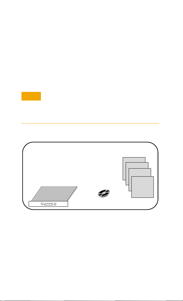
Agilent Technologies 82350B PCI GPIB Interface Card
Agilent IO Libraries for Instrument Control CD
82350B Getting Started Poster
82350B PCI GPIB Installation and Configuration Guide
82350B Warranty Statement
Software License Agreement
82350B PCI GPIB Interface Card Agilent Automation-
Ready CD
82350B Poster
82350B Guide
Warranty
Statement
Software License
Step 1: Checking Your Shipment
Your 82350B Interface shipment should include the items in
Figure 1-3. If any items are missing or damaged, keep the
shipping materials and contact Agilent Technologies. See
Chapter 3, “Contacting Agilent“ for addresses/telephone
numbers.
To reduce the risk of damaging the 82350B card, protect
the card from static electricity. Leave the card in its
anti-static bag until you are ready to install the card.
Handle the card only by the sheet metal frame or by the
card edges. Never touch any other part of the card.
Figure 1-3 82350B shipment contents
4 82350B Installation and Configuration Guide
Page 17

Installing and Configuring the 82350B 1
NOTE
Step 2: Installing Agilent IO Libraries Suite
You must have Administrator privileges to install Agilent IO
Libraries Suite Connection Expert.
This section describes how to install the Agilent IO Libraries
Suite on your PC. The Agilent IO Libraries Suite is a collection
of libraries and utilities that gives you the ability to use your
instruments from instrument control software.
You should install the Agilent IO Libraries Suite as your first
step before installing the hardware because it installs the
necessary software and drivers to control your instruments.
If possible, always use the most recent version of the Agilent
IO Libraries Suite. This version supports the newest interfaces
and operating systems, and has the most advanced features.
1 Verify that your PC meets the minimum system
requirements. Refer to the IO Libraries Web page at
www.agilent.com/find/iosuite or the IO Libraries
Suite Readme.
2 Close all applications on your computer. Insert the Agilent
Automation-Ready CD in your CD-ROM drive or download
and install the IO Libraries software from
www.agilent.com/find/iosuite.
3 Follow the instructions as prompted during the installation.
You can select either a Typical or a Custom installation:
• Ty pi c a l - In most cases, you can select the Typ i c a l
installation which installs the IO Libraries Suite using the
recommended settings.
• Custom - Select the Custom installation to:
a Install the IO Libraries Suite in another directory
(for 32-bit operating systems only).
b Save disk space by not installing interface manuals.
c Use Agilent 32-bit VISA with another vendor's VISA
on the same PC in side-by-side mode. Details on
side-by-side mode are available at
www.agilent.com/find/side-by-side-install or in the
IO Libraries Suite help.
82350B Installation and Configuration Guide 5
Page 18

1 Installing and Configuring the 82350B
4 After the IO Libraries suite is successfully installed, you will
see the IO icon on the Windows taskbar notification area.
Figure 1-4 IO icon on the Windows taskbar notification area
6 82350B Installation and Configuration Guide
Page 19

Installing and Configuring the 82350B 1
NOTE
NOTE
Step 3: Connecting Your Instruments
This step shows how to install an 82350B in a PCI slot in your
PC and how to connect GPIB instruments to the 82350B,
including:
• Installing the 82350B in your PC
• Connecting instruments to the 82350B
If you have not yet installed the Agilent IO Libraries Suite, go to
“Step 2: Installing Agilent IO Libraries Suite“ and install the
software BEFORE you install the 82350B in your PC.
To reduce the risk of damaging the 82350B, only handle the
card by the sheet metal frame or by its edges. Never touch any
other part of the card, including the PCI connector.
The 82350B is a 5V PCI card and will not fit in a 3.3V PCI slot.
Also, the 82350B will not fit in an EISA or ISA slot.
Installing the 82350B in your PC
1 Record the Card Serial Number. Remove the card from its
anti-static bag and record the Serial Number for future
reference. Save the anti-static bag so you can protect the
card if you need to remove the card from the PC.
The 82350B serial number is located on the white serial
number label on the card. The serial number contains 10
characters that encodes the country of manufacture,
Agilent year, workweek of manufacture and a unique
sequential number. The last four digits indicate a unique
serial number assigned sequentially to a 82350B.
Take precautions against static discharge when handling and
installing cards.
82350B Installation and Configuration Guide 7
Page 20

1 Installing and Configuring the 82350B
2 Remove PC Cover. Remove power from the PC and from all
of its peripherals. Then, remove the power cord from the PC.
Unlock and remove the cover from the PC to allow access to
the I/O slots. See your PC documentation for instructions.
Figure 1-5 Remove the PC cover
3 Remove a Cover Plate. Remove one of the PC back panel
cover plates. The 82350B is a 5V PCI card and will not fit in a
3.3V PCI slot or in an EISA or ISA slot. Choose a 5V PCI slot
that will give adequate clearance for the GPIB connector.
Figure 1-6 Remove the card slot
4 Install the 82350B. Insert the 82350B Interface Card edge
connector into the PCI expansion slot connector of the PC.
Make sure the interface is fully seated by pushing firmly on
the top edge of the card with the palm of your hand. The
GPIB connector should extend through the back panel
opening to allow GPIB cable connection. If you install more
than one 82350B, you may want to install the cards so there
is at least one empty slot between 82350Bs. When inserting
the 82350B, be sure to hold the card by its edges. Also, be
careful with the metal faceplate around the GPIB connector
as the faceplate can be bent.
8 82350B Installation and Configuration Guide
Page 21

Installing and Configuring the 82350B 1
Figure 1-7 Install the 82350B
5 Replace the Cover Plate Screw. This will hold the 82350B
in place. Save the blank cover plate for use if the 82350B is
later removed. Replace the PC cover(s) as described in your
PC documentation.
Figure 1-8 Replace the cover plate screw
82350B Installation and Configuration Guide 9
Page 22

1 Installing and Configuring the 82350B
Connecting instruments to the 82350B
After the 82350B is installed in your PC, the next step is to
connect your GPIB instruments to the installed 82350B.
Suggested steps follow. When you have made the
connections, go to “Step 4: Configuring the 82350B“.
1 Review Connection Guidelines. The recommended method
for connecting a GPIB system is a linear arrangement with
the system controller (PC) at one end of the system.
However, a GPIB system can also be connected together in
a star, linear, or a combination configuration as long as the
total number of devices on the system is
guidelines are followed:
• To minimize stress on connector mountings, no more
than three cable connectors blocks should be stacked on
top of one another. The GPIB connector screws should
be finger-tightened only.
• Minimize cable length as much as possible. All system
devices must have tri-state drivers and must be powered
on. Systems with devices not using tri-state drivers are
limited to transfer rates < 250 Kbytes/sec.
• For operation with data transfer rates <500 Kbytes/sec,
the total length of all GPIB cables is ≤2 meters times the
number of devices connected together, up to a maximum
of 20 meters.
• For operation with data transfer rates > 500 Kbytes/sec,
the total length of all GPIB cables is > 1 meter times the
number of devices connected together, up to a maximum
of 15 meters.
• The length between adjacent devices is not critical as
long as the overall restriction is met. GPIB bus extenders
are available that allow operation over much greater
distances.
2 Connect GPIB Cables to the 82350B. Connect a separate
GPIB cable to each installed 82350B. Tighten the GPIB
connector screws finger-tight only. (The screwdriver slots
are for removal purposes only.) Two examples follow
showing how to connect a single GPIB instrument or how to
connect multiple GPIB instruments.
≤14 and these
10 82350B Installation and Configuration Guide
Page 23

Installing and Configuring the 82350B 1
CAUTIONCAUTION
GPIB Cable
GPIB Connector. Connect to
GPIB port on GPIB Instrument.
GPIB Connector. Connect to GPIB
connector on 82350 GPIB Interface
Card installed in PC.
PC
Instrument
CAUTIONCAUTION
For information or to purchase Agilent GPIB cables, see
www.agilent.com/find/io.
Example: Connecting a single GPIB instrument
Figure 1-9 shows connections from a single GPIB instrument
to the GPIB connector of an 82350B installed in your PC. You
may want to record the primary GPIB address of the attached
instrument for future programming use. After making the
connections, reconnect the PC power cord and apply power to
the PC and to attached peripherals/instruments.
82350B Installation and Configuration Guide 11
To avoid damage to the connectors, only finger-tighten the
connectors.
Figure 1-9 Connecting a single GPIB instrument
Example: Connecting Multiple GPIB Instruments
Figure 1-10 shows one way to connect three GPIB instruments
to an Agilent 82350B GPIB Interface Card. You may want to
record the primary GPIB address of each attached instrument
for future programming use. After making the connections,
reconnect the PC power cord and apply power to the PC and
attached peripherals/instruments.
To avoid damage to the connectors, only finger-tighten the
connectors.
Page 24

1 Installing and Configuring the 82350B
NOTE
GPIB Cable
GPIB Connector.
Connect to GPIB port
on GPIB Instrument 1.
GPIB Connector. Connect to GPIB
connector on 82350 Interface Card.
PC
Instrument 1
Instrument 2
Instrument 3
Although the figure shows cable connections to GPIB
Instrument 1, the connection can be to any GPIB instrument in
the system.
Figure 1-10 Connecting multiple GPIB instruments
12 82350B Installation and Configuration Guide
Page 25

Installing and Configuring the 82350B 1
NOTE
Step 4: Configuring the 82350B
This step shows how to configure a Windows
XP/Vista/7/8/Server 2008 R2 operating system for a PC that
has an 82350B installed.
Installing configuration files
1Apply Power. Apply power to the PC and to the installed
GPIB instruments. As Windows starts again, a Found New
Hardware Wizard may start.
2 Install Configuration Files. Click Next> to accept the
defaults. (Make sure that you have installed Agilent IO
Libraries Suite first. You will not need a CD.) Click Finish to
complete the installation.
3 Open Connection Expert. Click the Agilent IO Control icon
on the Windows taskbar notification area, and then click
Agilent Connection Expert. When the main screen appears,
you will see a map of the system connections in the
Instrument I/O on this PC pane (also called “Explorer
Pane”). If you see your interface and instruments in the
Explorer Pane, you are ready to go!
For help with Connection Expert, refer to the Agilent IO
Libraries Suite help file. This help file is available from the IO
Control > Documentation menu.
82350B Installation and Configuration Guide 13
Page 26

1 Installing and Configuring the 82350B
NOTE
Configuring the 82350B interface
1 Open Connection Expert. Click the Agilent IO Control icon
(IO icon on the Windows taskbar notification area) and then
click Agilent Connection Expert. When the Connection
Expert window appears, highlight and right-click the GPIB
interface in the explorer view (tree view at the center of the
window) and then click Change Properties... to display the
Agilent 82350B PCI GPIB Interface dialog box.
Figure 1-11 Agilent Connection Experts
For a description of Connection Expert and the Agilent IO
Libraries Suite, see the Agilent IO Libraries Suite Online Help.
To access this Help file, click the IO Control and select
Documentation > IO Libraries Suite Help.
14 82350B Installation and Configuration Guide
Page 27

Installing and Configuring the 82350B 1
NOTE
2 Configure GPIB Card Parameters. When the Agilent
82350B PCI GPIB Interface dialog box appears, set the
VISA interface ID, SICL interface ID, Logical unit, and GPIB
address values as required.
Also, verify that this is the System controller for the GPIB to
which it is attached (this is the typical operating mode).
(See the System Controller discussion below.) Then, click
the OK button. Some guidelines to set these values follow.
Changes to certain properties of the 82350B, including:
• GPIB address
• System controller flag
• SICL interface ID
• Logical unit
will not take effect until you reboot your PC. If you choose not
to reboot immediately, Connection Expert will display a
warning icon until you reboot.
Figure 1-12 Configure GPIB card parameters
82350B Installation and Configuration Guide 15
Page 28

1 Installing and Configuring the 82350B
Table 1-1 82350B GPIB interface card configuration parameters
VISA
Interface ID
GPIB
Address
System
Controller
SICL
Interface ID
Logical Unit Number that SICL uses to uniquely identify this 82350B
Symbolic name that VISA uses to uniquely identify this GPIB
interface. The default VISA interface ID is GPIB0. The
82350B interface ID for VISA must begin with the string
GPIB and have an integer appended to it, such as GPIB0,
GPIB1, GPIB2, etc. Remember this value to properly address
GPIB devices in your VISA applications.
Address of this GPIB interface controller on the GPIB bus. It
is usually 21 if the GPIB interface is a System Controller or
20 if the GPIB interface is a non-System Controller (see
System Controller, following). These addresses are chosen
by convention but any address in the range 0 - 30, inclusive,
may be used.
Determines if this interface controls which bus devices talk
and which bus devices listen. If several devices exist on a
bus, be sure each has a unique GPIB bus address and only
one device is the System Controller. Each GPIB interface has
its own independent bus. Thus, each interface may be a
System Controller as long as it is not chained together with
other GPIB interfaces. However, two or more System
Controllers on the same bus will cause the bus to be
inoperative.
Symbolic name that SICL uses to uniquely identify this GPIB
interface. The default Interface ID is gpib0. The SICL
interface ID must be a unique string of alphanumeric
characters, starting with a letter. Remember this value and
the logical unit number to properly address GPIB devices in
your SICL applications.
interface. The logical unit number is an integer in the range
of 0 - 10000. Remember this value and the SICL interface ID
to properly address the GPIB interface in your SICL
applications.
3 Repeat Steps for Other Cards. If you have installed more
than one 82350B in your PC, repeat these steps for the
remaining cards. Then, go to “Step 5: Communicating with
your instruments“.
16 82350B Installation and Configuration Guide
Page 29

Installing and Configuring the 82350B 1
NOTE
Step 5: Communicating with your instruments
After the 82350B has been configured and you have connected
your GPIB instruments to the 82350B, the next step is to verify
communication between your PC and the instruments using
the Interactive IO utility. After communication has been
established, you can begin programming the instruments using
VISA, VISA COM, SICL, or SCPI commands.
This section includes:
• Verifying instruments communication
• Programming your instruments (optional)
Verifying instrument communication
When the Agilent IO Libraries Suite was installed on your PC,
an I/O utility called Interactive IO was also installed. You can
use Interactive IO to verify communication between your PC
and connected GPIB instruments.This section shows one way
to use Interactive IO to verify instrument communication.
Once your GPIB interface has been configured in Connection
Expert, if you can see the attached GPIB instrument(s) in the
Connection Expert explorer and see their IDN string
information in the detail pane then communication has been
verified. Interactive IO allows you to manually verify
communication and send specific commands to your
instruments.
To use Interactive IO to send a *IDN? (identification) query to
an instrument:
1 Select the instrument by clicking its icon in the Connection
Expert explorer view.
2 Right-click the instrument and click Send Commands To
This Instrument to display the Interactive IO window. For
information on Interactive IO, including a list of common
commands and their meanings, click Help > Help Topics.
3 *IDN? is the default command. Click Send & Read to send
the identification query to the instrument and display its
reply in the Interactive IO window.
82350B Installation and Configuration Guide 17
Page 30

1 Installing and Configuring the 82350B
4 To send other commands, click Commands> to select from
a list of common commands, or type a command into the
Command: field. If you experience timeout errors for some
commands, click Options to change the timeout value.
Figure 1-13 Agilent Interactive IO
Programming your instruments (optional)
This section provides an introduction to programming GPIB
instruments via the 82350B PCI GPIB interface using the
Agilent VISA and SICL IO Libraries. You can program in various
languages/applications, including Visual Basic, Visual C++,
and Agilent VEE.
See the applicable User’s Guide, such as the Visual Basic
User’s Guide, for programming guidelines. You can also find
additional programming examples using various IO Libraries
and instrument drivers in the instrument User’s Guide. After
the 82350B is successfully installed and configured, it should
act as a transparent interface for programming GPIB
instruments.
For information on programming using Agilent VISA, see the
Agilent VISA User’s Guide. For information on VISA COM and
for function references for VISA, VISA COM, and SICL, see the
IO Libraries Suite Online Help.
18 82350B Installation and Configuration Guide
Page 31

Installing and Configuring the 82350B 1
Accessing Programming Manuals and Help
You can access .pdf copies of the Agilent VISA User’s Guide
and the Agilent SICL User’s Guide for Windows from the IO
icon on the Windows taskbar notification area. Adobe Acrobat
Reader is required to view these manuals.
To access the Agilent VISA User’s Guide, click the IO icon and
then click Documentation > VISA Users Guide. To access the
Agilent SICL User’s Guide for Windows, click the IO icon and
then click Documentation > SICL Users Guide. To access
VISA COM information, and function references for VISA, VISA
COM, and SICL, click the IO icon and then click Documentation
> Help Topics > VISA COM Help.
Example: GPIB Interface Configuration
An I/O interface consists of a hardware interface and a
software interface. One purpose of the Connection Expert
utility is to associate a unique software interface ID with a
hardware interface. The Agilent IO Libraries Suite uses an
Interface ID or Logical Unit Number to identify an interface.
This information is passed in the parameter string of the
viOpen function call in a VISA program or in the iopen function
call in a SICL program.
For example, the GPIB interface system in Figure 1-14 consists
of a Windows PC with two 82350B GPIB cards connected to
three GPIB instruments via GPIB cables. For this system, the
Connection Expert utility has been used to assign GPIB card
#1 a VISA interface ID of “GPIB0” and a SICL interface ID
of “gpib0”.
Connection Expert has also been used to assign GPIB card #2
a VISA interface ID of “GPIB1” and a SICL interface ID of
“gpib1”. With these names assigned to the interfaces, the
VISA/SICL addressing is as shown in the figure. Since unique
names have been assigned by Connection Expert, you can use
the VISA viOpen command to open the I/O paths to the GPIB
instruments. Or, you can use the SICL iopen command to open
the I/O paths shown.
82350B Installation and Configuration Guide 19
Page 32

1 Installing and Configuring the 82350B
5
82350 GPIB Card #1
Windows PC
3
3
GPIB InstrumentsGPIB CableInterface VISA/SICL IDs
82350 GPIB Card #2
VISA Interface ID SICL Interface ID
"GPIB0" "gpib0 "
"GPIB1" "gpib1 "
VISA/SICL Addressing
VISA: viOpen (... "GPIB0::5::INSTR "...)
viOpen (... "GPIB0::3 ::INSTR"...)
viOpen (... "GPIB1::3 ::INSTR"...)
SICL: iopen ("gpib0, 5")
iopen ("gpib0,3")
iopen ("gpib1,3")
GPIB Interface (82350 PCI GPIB Cards)
Open IO path to GPIB instrument at address 5 using 82350 Card #1
Open IO path to GPIB instrument at address 3 using 82350 Card #1
Open IO path to GPIB instrument at address 3 using 82350 Card #2
Open IO path to GPIB instrument at address 5 using 82350 Card #1
Open IO path to GPIB instrument at address 3 using 82350 Card #1
Open IO path to GPIB instrument at address 3 using 82350 Card #2
Figure 1-14 Interface configuration for multiple instruments
20 82350B Installation and Configuration Guide
Page 33

Installing and Configuring the 82350B 1
Set 82350B Read/Write Performance Mode
The 82350B card read and write calls use one of two modes:
• Polling. Bytes are transferred to/from the card, one at a
time. Polling mode is advantageous for transferring a small
number of bytes because the setup overhead is very low,
but it does require CPU involvement for each
byte transferred.
• Interrupt. An entire buffer is transferred to/from the card
without CPU involvement. Interrupt mode is advantageous
for transferring large buffers because the higher per byte
transfer rate more than compensates for the relatively long
interrupt setup overhead.
The default behavior of the 82350B driver is to use Polling
mode for transfers of 256 bytes or less and to use Interrupt
mode for larger transfers. You can modify this default behavior
by doing the following:
SICL: The SICL ihint(id, hint) function can be called to modify
the read/write behavior for on a SICL session. The hint values
allowed are:
1 I_HINT_DONTCARE (default value): Use Interrupt mode for
transfer requests larger than 256 bytes, otherwise, use
Polling mode.
2 I_HINT_USEPOLL: Use the Polling mode.
3 I_HINT_IO: Use the Interrupt mode.
VISA: The VISA viSetAttribute(vi,
VI_ATTR_DMA_ALLOW_EN, attrValue) function can be called
to modify the read/write behavior for a VISA session. The
VI_ATTR_DMA_ALLOW_EN values allowed are:
• VI_TRUE (default value): Use Interrupt mode for transfer
requests larger than 256 bytes, otherwise, use
Polling mode.
• VI_FALSE: Use the Polling mode.
82350B Installation and Configuration Guide 21
Page 34

1 Installing and Configuring the 82350B
Some additional factors to consider are:
• The settings discussed above are per session. This means
you can open multiple sessions to a device and set different
transfer modes for different sessions. The actual mode used
will then depend on which session you are using for the
read/write calls.
• In both SICL (with hint = I_HINT_DONTCARE) and VISA
(with VI_ATTR_DMA_ALLOW_EN = VI_TRUE), the size of
the read request (as specified by bufsize in a SICL iread() or
count in a VISA viRead() function call) will determine the
mode used even if the number of bytes actually read is less.
• The default formatted IO read buffer size is 4096 so when
using this default size, formatted reads in SICL
(with hint = I_HINT_DONTCARE) and VISA (with
VI_ATTR_DMA_ALLOW_EN = VI_TRUE) will use Interrupt
mode even when a small number of bytes are expected.
• The default formatted IO write buffer size is 128 so when
using this default size, formatted writes in SICL
(with hint = I_HINT_DONTCARE) and VISA (with
VI_ATTR_DMA_ALLOW_EN = VI_TRUE) will use Polling
mode even sending a large number of bytes.
• In SICL, Polling mode will always be used for the iread(),
ifread(), and iscanf() regardless of the above settings, when
a termchr is set (itermchr() is not set to –1.
• In VISA, Polling mode will always be used for viRead(),
viBufRead(), and viScanf() regardless of the above settings,
when VI_ATTR_TERM_CHAR_EN = VI_TRUE.
The crossover point at which the Interrupt mode becomes
faster then the Polling mode depends on the CPU speed, with a
faster CPU having a higher crossover point.
22 82350B Installation and Configuration Guide
Page 35

Agilent 82350B PCI GPIB Interface
NOTE
Installation and Configuration Guide
2 Troubleshooting Guidelines
This chapter shows suggested troubleshooting steps for
Agilent 82350B GPIB interface.
Additional troubleshooting information appears in the Agilent
IO Libraries Suite Online Help and on the Web at
http://www.agilent.com/find/iolib.
Agilent Technologies
23
Page 36

2 Troubleshooting Guidelines
Check IO Libraries Suite
Installation
1 82350 Hardware Checks
Check Cables/
Connections/Power
Check for GPIB
Driver Files
Install Libraries (if GPIB
Already Installed)
Check IO Control
Operation
Check Device Manager
Typical Causes
Bad GPIB cables/connections
or power not ON for PC or
instruments.
Typical Causes
GPIB card drivers not installed
or GPIB card not properly
configured.
Typical Causes
Agilent IO Libraries Suit e not
installed or improper IO
Libraries Suite c onfiguration
Disable Connection Expe rt
Auto-Discovery
Set 82350 Read/Write
Performance Mode
After Doing These Checks:
- If the cause is not identified,
see
GPIB Software Checks
- If the cause is identified as an
82350 hardware problem,
contact Agilent to return the
82350.
After Doing These Checks:
- If the cause is not i dentified,
see
Agilent IO Libraries Checks
- If the cause is identified, but the
problem cannot be fixed, contact
Agilent for support.
After Doing These Checks:
- If the cause is not i dentified
or the problem cannot be
fixed, contact Agilent for
support.
Check BIOS/Interrupts
Settings
2 82350 Software Checks 3 IO Libraries Checks
Other Hardware Checks
Troubleshooting Overview
A suggested troubleshooting flowchart for the 82350B,
installed instruments, and the Agilent IO Libraries Suite
follows. We suggest that you start at Step 1 and then go to
Step 2 and then to Step 3, as required.
24 82350B Installation and Configuration Guide
Figure 2-1 Troubleshooting overview
Page 37

82350B Hardware Checks
NOTE
This section gives guidelines to make hardware
troubleshooting checks for the 82350B, including:
• Check cables/connections/power
• Check device manager
Check cables/connections/power
We suggest you start your troubleshooting sequence by
performing the following hardware checks. If the hardware
checks do not solve the problem, see “82350B Software
Checks“.
There are no user-serviceable parts for the 82350B. If you
suspect a hardware failure for the 82350B, contact Agilent for
instructions to return the unit.
1 Check GPIB cable connections. Check all GPIB cables for
good connection to the GPIB connector on the 82350B
installed in your PC and the GPIB cable connections
between all connected GPIB instruments. An improperly
attached GPIB connector can cause the bus to malfunction.
2 Check GPIB cables for damage. Check all GPIB cables for
cuts/damage and check for bent/misaligned/crushed
connector pins. Replace cables as required.
3 Disconnect/Reconnect GPIB cables. If Steps 1 and 2 do
not solve the problem, try disconnecting and reconnecting
(or replacing) GPIB cables.
4 Check PC/instrument power-on. Verify that the PC and all
connected GPIB instruments are functional and are
powered ON. Verify that host computer is not in a
Suspended power management state.
5Reboot your PC. If doing Steps 1, 2, 3 or 4 does not solve the
problem, reboot the PC. If this does not solve the problem,
go to “Check Device Manager”.
Troubleshooting Guidelines 2
82350B Installation and Configuration Guide 25
Page 38

2 Troubleshooting Guidelines
Check Device Manager
You can use the Windows Device Manager to reinstall the
82350B or equivalent, as required. Go to Device Manager by
selecting Start > Control Panel > System > Hardware >
Device Manager.
For Windows 8, right-click the bottom-left corner of the
Desktop and select Device Manager.
From the Device Manager, select 82350B and then Properties.
Select Driver and click Reinstall Driver.
This will allow the Windows Plug and Play Manager to begin
searching for a driver for the 82350B. Since Device Manager
may have disabled the 82350B device, click Enable to restart
the 82350B. If this does not resolve the problem, go to “82350B
Software Checks“.
82350B Software Checks
This section provides guidelines for 82350B BIOS/Interrupts
Settings software checks.
Check BIOS/Interrupts Settings
If Connection Expert reports finding an 82350B card with Serial
Number ffffffff, this is typically caused by PCI cards not
properly being configured. Try the following steps. If these
steps do not work, remove and re-install the 82350B and then
reconfigure the card.
1 Upgrade your system BIOS to the latest version. New
computers often have newer BIOSs available. When
installing new BIOS, ensure the BIOS Installed O/S setting
is set correctly. This determines what software will
configure all the Plug and Play cards in your system. Either
the BIOS or the operating system can perform the task of
querying all the cards to determine their resource needs,
picking a valid configuration for all these cards, and telling
the cards what their actual resource settings are.
26 82350B Installation and Configuration Guide
Page 39

Troubleshooting Guidelines 2
2 If your computer locks up or freezes after installing.
Typically, this is caused by interrupt conflicts with other
drivers in the system. Some non-Agilent PCI cards do not
work properly when sharing IRQ line.
To validate the driver of the 82350B card, go to Device
Manager by selecting Start > Control Panel > System >
Hardware > Device Manager. For Windows 8, right-click
the bottom-left corner of the Desktop and select Device
Manager. Find the 82350B card and check that all other
cards on the same IRQ have a valid driver, not the big yellow
question mark.
When the IRQ is asserted, the OS calls each ISR in turn until
one of them returns TRUE (meaning that it handled the
interrupt). The ISR’s responsibility is to correctly return
TRUE if its device was interrupting or FALSE if not. Drivers
that return TRUE, even though they did not service the interrupt, will cause problems.
To perform driver workarounds, you can upgrade the drivers
for devices sharing an IRQ with Agilent, including, but not
limited to, your video drivers, your LAN drivers, Agilent IDE
and/or SCSI drivers, and your sound drivers
3Reconfigure your PC. Configure your PC so as to not share
IRQ lines. Many PCI cards have bugs when sharing IRQ
lines. You may or may not be able to do this on all PCs. Many
PCs can be configured using the setup option when the PC
is booting
.
82350B Installation and Configuration Guide 27
Page 40

2 Troubleshooting Guidelines
NOTE
Agilent IO Libraries Suite Checks
This section gives guidelines to troubleshoot problems
involving the Agilent IO Libraries Suite, including:
• Check IO Libraries Suite installation
• Check IO Control operation
• Install IO Libraries Suite (if 82350B was Installed First)
Check IO Libraries Suite installation
Start your Agilent IO Libraries Suite troubleshooting sequence
by verifying IO Libraries Suite installation. If the IO Libraries
Suite is installed, go to Check IO Control Operation.
1 Check Agilent IO Libraries version. If a version of the IO
Libraries Suite has been installed, the IO icon is normally
displayed on the Windows taskbar notification area.
Figure 2-2 IO icon on the Windows taskbar notification area
If possible, you should always use the current version of the
Agilent IO Libraries Suite. This version supports the newest
interfaces and operating systems, and has the most advanced
features. However, you may need an earlier version of the IO
Libraries Suite to support an older interface or operating
system. For example, Agilent IO Libraries Suite 14.0 is required
for Windows 98SE or Windows Me. If you need an earlier
version of Agilent IO Libraries, go to
http://www.agilent.com/find/iolib to locate the version
you need.
28 82350B Installation and Configuration Guide
Page 41

Troubleshooting Guidelines 2
a If the IO icon is displayed, click the icon and select About
Agilent IO Control to display the version. The version
must be 15.0 or greater.
b If the IO icon is not displayed, a version of the IO Libraries
Suite may still be installed. To verify this, check for
Agilent Connection Expert in the Start menu or the Start
Screen (Windows 8).
c If found, launch the Agilent Connection Expert and select
View > Agilent IO Control to place a check mark next to
the Agilent IO Control selection.
d If Agilent Connection Expert is not found in the Start
menu or the Start Screen (Windows 8), no version of
Agilent IO Libraries is installed. In this case, or if the
installed version is not 15.0 or greater, you must install
the newer version (see Step 2).
2 Install Agilent IO Libraries Suite (as required). If version
15.0 or greater of the Agilent IO Libraries is not installed on
your PC, install the IO Libraries Suite. Otherwise, go to
Check IO Control operation.
Check IO Control operation
When the Agilent IO Libraries Suite is installed, an IO Control
is created. When the IO Control is active, it is displayed as an
IO icon on the Windows taskbar notification area. If the IO
Control is deactivated, SICL/VISA applications that are
running with the 82350B will be unable to open sessions.
By default, the IO Control is always active after the Agilent IO
Libraries Suite is installed and the IO icon is displayed.
However, there may be times when the IO Control is active and
the IO icon is not displayed. There are two ways that the IO
icon can be hidden:
• Hide Agilent IO Control. Click the IO icon and and select
Hide Agilent IO Control from the drop down menu.
Alternately, you can uncheck View | Agilent IO Control in
Connection Expert. This will hide the IO icon, but will not
deactivate the IO Control.
• Click Exit. Click the IO icon and select Exit from the drop
down menu. A dialog box explaining the consequences of
removing the IO appears. Click Yes to hide the IO icon and
deactivates the IO Control.
82350B Installation and Configuration Guide 29
Page 42

2 Troubleshooting Guidelines
NOTE
If the IO icon is not displayed, either the IO icon display has
been turned off and/or the IO Control (and associated
iprocsvr.exe) is not active. In this case, launch the Agilent
Connection Expert and select View > Agilent IO Control to
place a check mark next to the Agilent IO Control selection to
restart the IO Control and display the IO icon.
Install IO Libraries Suite (if 82350B was installed first)
If you installed the 82350B before installing the Agilent IO
Libraries Suite software, follow these steps to install and
configure the IO Libraries Suite and the necessary drivers for
your card.
1 Install the Agilent IO Libraries Suite as described in “Step 2:
Installing Agilent IO Libraries Suite" on page 5.
2 If the Connection Expert utility does not recognize your
82350B and display it as a PCI GPIB Interface, you may
need to use Windows Device Manager to associate the
correct drivers with your card. Follow the steps below:
a Start the Windows Device Manager as follows:
Select Start > Control Panel > System > Hardware >
Device Manager. For Windows 8, right-click the
bottom-left corner of the Desktop and select
Device Manager.
b Find the PCI Simple Communications Controller in the
Device Manager, and select Update Driver...
c Allow Windows to find and install the driver
automatically. You are not require to insert a CD.
On older operating systems, you may be asked to insert the
'HP I/O Libraries' CD. Depending on the file you are prompted
for and on the operating system, you should be able to find the
needed file in one of the following directories:
• C:\windows\inf
• C:\windows\system
• C:\windows\system32
• C:\windows\system32\drivers
The card may be identified as a Hewlett-Packard card. This is
necessary for backward compatibility.
30 82350B Installation and Configuration Guide
Page 43

Agilent 82350B PCI GPIB Interface
Installation and Configuration Guide
3 82350B Specifications and Information
This chapter provides general information for the 82350B PCI
GPIB Interface.
Agilent Technologies
31
Page 44

3 82350B Specifications and Information
General Requirements
Before installing your Agilent 82350B, make certain your PC
meets or exceeds the following criteria. Ta b le 3- 1 shows the
general requirements for installing the 82350B.
Table 3-1 General requirements
Software/Hardware Requirement
Minimum system requirements Windows XP/Vista/7/8/
Software required Agilent IO Libraries Suite 15.0
PCI bus slot 5-V PCI slot, 32 bits
Support standards PCI rev 2.1
Server 2008 R2
and above
IEEE 488.1 and IEEE 488.2
compatible
32 82350B Installation and Configuration Guide
Page 45

82350B Specifications and Information 3
General Characteristics
All characteristics are typical performance values and are not
warranted. Ta b le 3- 2 shows the general characteristics of
the 82350B.
Table 3-2 General characteristics
General characteristics Requirement
Power
Connectors
Maximum data rate
Maximum instrument
connection
Buffering
Configuration
EMC and safety *
Warranty
Length, width, and height
Weigh t
Backplane +5 V PCI
Standard 24-pin GPIB (IEEE-488)
+5V PCI
More than 900 KB/s
14 instruments—daisy chain via GPIB
Built-in
Plug-and-Play
IEC 61326-1 Group 1, Class A
IEC 61010-1
3 years
122 mm (L) x 122 mm (W) x 22 mm (H)
(a full-height PCI card)
0.091 kg
82350B Installation and Configuration Guide 33
Page 46

3 82350B Specifications and Information
Accessing an Electronic Copy of this Guide
There are two ways you can access an electronic (.pdf) version
of this guide, as follows. You will need Adobe Acrobat Reader
Version 3.0 or later to view the electronic version.
• Access from the IO Control. After the Agilent IO Libraries
Suite is installed, the IO icon appears on the Windows
taskbar notification area. To access an electronic version of
this guide, click the IO icon, then click Documentation and
then click 82350B PCI GPIB Users Guide.
• Access from the Web. To access an electronic version of
this guide, click the IO icon, then click Documentation, then
Interface Manuals, and then click 82350B PCI GPIB
User’s Guide.
34 82350B Installation and Configuration Guide
Page 47

82350B Specifications and Information 3
Contacting Agilent
You can reach Agilent Technologies at this
telephone number in the United States:
United States Call Center: 1-800-829-4444
For other locations, contact your country’s Agilent support
organization. A list of contact information for other countries is
available on the Agilent Web site at:
www.agilent.com/find/assist
A list of other Agilent Web sites is as follows.
Table 3-3 Agilent Web sites
URL Description
www.agilent.com/find/assist Agilent Technologies “Contact Us” page
www.agilent.com/find/iolib Update the Agilent IO Libraries
www.agilent.com/find/ADN Connectivity resources all in one place
www.agilent.com/find/
techsupport
www.agilent.com/find/
connectivity
Suite software
Technical support information, including
manuals, application notes, FAQs, and
software and firmware downloads
For connection, communication and
control of test instruments from your
computer, you can find out the latest in
connectivity.
82350B Installation and Configuration Guide 35
Page 48

3 82350B Specifications and Information
THIS PAGE HAS BEEN INTENTIONALLY LEFT BLANK.
36 82350B Installation and Configuration Guide
Page 49

Index
A
Agilent IO Control icon, 14
Agilent VEE, 18
Agilent Web sites, 35
Agilent, contacting, 35
C
configuration parameters, setting, 26
Configuring the 82350B, 13
connecting 82350B to PC, 7
connecting 82350B to USB hub, 12
Connecting GPIB Instruments, 17
contacting Agilent, 35
crossover point, 22
E
examples
Connecting Multiple GPIB Instruments, 11
GPIB Interface Configuration, 19
G
General Characteristics, 33
GPIB
crossover point, 22
interrupt mode, 21
Logical Unit, 16
polling mode, 21
SICL interface ID, 16
System Controller, 16
VISA Interface ID, 16
I
I/O interface, 19
ihint, 21
Initial Operating States, 25
initial operating states, 25
Installing Agilent IO Libraries Suite, 5
installing the 82350B
configuring the 82350B, 13
Interactive IO, 17
interface ID, 19
interrupt, 27
iopen, 19
82350B Installation and Configuration Guide 37
Page 50

L
LED states, 25
logical unit number, 19
S
setting configuration parameters, 26
setting default configuration, 13
setting timeout floor values, 20
standards, 32
system requirements, checking, 5
T
troubleshooting
GPIB crossover point, 22
GPIB interrupt mode, 21
GPIB polling mode, 21
V
viOpen, 19
viSetAttribute, 21
W
Web, 34
Web sites, Agilent, 35
38 82350B Installation and Configuration Guide
Page 51

www.agilent.com
Contact us
To obtain service, warranty, or technical
assistance, contact us at the following phone
or fax numbers:
United States:
(tel) 800 829 4444 (fax) 800 829 4433
Canada:
(tel) 877 894 4414 (fax) 800 746 4866
China:
(tel) 800 810 0189 (fax) 800 820 2816
Europe:
(tel) 31 20 547 2111
Japan:
(tel) 0120 (421) 345 (fax) 0120 (421) 678
Korea:
(tel) (080) 769 0800 (fax) (080) 769 0900
Latin America:
(tel) (305) 269 7500
Ta i w an :
(tel) 0800 047 866 (fax) 0800 286 331
Other Asia Pacific Countries:
(tel) (65) 6375 8100 (fax) (65) 6755 0042
Or visit Agilent World Wide Web at:
www.agilent.com/find/assist
Product specifications and descriptions in this
document are subject to change without
notice. Always refer to the Agilent Web site
for the latest revision.
© Agilent Technologies, Inc. 2002–2013
Printed in Malaysia
Eleventh Edition, March 19, 2013
82350-90004
Agilent Technologies
 Loading...