

Page 1

Agilent Technologies
N5161A/62A/81A/82A/
83A
MXG Signal Generators
User’s Guide
Agilent Technologies
Page 2

Notices
CAUTION
WARNING
© Agilent Technologies, Inc. 2006-2009
No part of this manual may be reproduced in
any form or by any means (including electronic storage and retrieval or translation
into a foreign language) without prior agreement and written consent from Agilent
Technologies, Inc. as governed by United
States and international copyright laws.
Manual Part Number
N5180-90003
Edition
January 2009
Printed in USA
Agilent Technologies, Inc.
3501 Stevens Creek Blvd.
Santa Clara, CA 95052 USA
Warranty
The material contained in this document is provided “as is,” and is subject to being changed, without notice,
in future editions. Further, to the maximum extent permitted by applicable
law, Agilent disclaims all warranties,
either express or implied, with regard
to this manual and any information
contained herein, including but not
limited to the implied warranties of
merchantability and fitness for a particular purpose. Agilent shall not be
liable for errors or for incidental or
consequential damages in connection with the furnishing, use, or performance of this document or of any
information contained herein. Should
Agilent and the user have a separate
written agreement with warranty
terms covering the material in this
document that conflict with these
terms, the warranty terms in the separate agreement shall control.
Tec hn ol og y L i ce ns es
The hardware and/or software described in
this document are furnished under a license
and may be used or copied only in accordance with the terms of such license.
Restricted Rights Legend
U.S. Government Restricted Rights. Software and technical data rights granted to
the federal government include only those
rights customarily provided to end user customers. Agilent provides this customary
commercial license in Software and technical data pursuant to FAR 12.211 (Technical
Data) and 12.212 (Computer Software) and,
for the Department of Defense, DFARS
252.227-7015 (Technical Data - Commercial
Items) and DFARS 227.7202-3 (Rights in
Commercial Computer Software or Computer Software Documentation).
Safety Notices
A CAUTION notice denotes a hazard. It calls attention to an operating procedure, practice, or the like
that, if not correctly performed or
adhered to, could result in damage
to the product or loss of important
data. Do not proceed beyond a
CAUTION notice until the indicated
conditions are fully understood and
met.
A WARNING notice denotes a
hazard. It calls attention to an
operating procedure, practice, or
the like that, if not correctly performed or adhered to, could result
in personal injury or death. Do not
proceed beyond a WARNING
notice until the indicated conditions are fully understood and
met.
Installation Guide
Page 3

Contents
1 Signal Generator Overview
Signal Generator Features . . . . . . . . . . . . . . . . . . . . . . . . . . . . . . . . . . . . . . . . . . . . . . .2
Modes of Operation . . . . . . . . . . . . . . . . . . . . . . . . . . . . . . . . . . . . . . . . . . . . . . . . . . .4
Continuous Wave . . . . . . . . . . . . . . . . . . . . . . . . . . . . . . . . . . . . . . . . . . . . . . . . . .4
Swept Signal . . . . . . . . . . . . . . . . . . . . . . . . . . . . . . . . . . . . . . . . . . . . . . . . . . . . .4
Analog Modulation . . . . . . . . . . . . . . . . . . . . . . . . . . . . . . . . . . . . . . . . . . . . . . . . .4
Digital Modulation (N5162A/82A with Options 651, 652, or 654 Only) . . . . . . . . . . . . . . .4
Front Panel Overview – N5181A/82A MXG . . . . . . . . . . . . . . . . . . . . . . . . . . . . . . . . . . .5
1. Host USB . . . . . . . . . . . . . . . . . . . . . . . . . . . . . . . . . . . . . . . . . . . . . . . . . . . . .5
2. Display . . . . . . . . . . . . . . . . . . . . . . . . . . . . . . . . . . . . . . . . . . . . . . . . . . . . . . .5
3. Softkeys . . . . . . . . . . . . . . . . . . . . . . . . . . . . . . . . . . . . . . . . . . . . . . . . . . . . . .5
4. Numeric Keypad . . . . . . . . . . . . . . . . . . . . . . . . . . . . . . . . . . . . . . . . . . . . . . . . .6
5. Arrows and Select. . . . . . . . . . . . . . . . . . . . . . . . . . . . . . . . . . . . . . . . . . . . . . . .6
6. Page Up . . . . . . . . . . . . . . . . . . . . . . . . . . . . . . . . . . . . . . . . . . . . . . . . . . . . . .6
7. MENUS . . . . . . . . . . . . . . . . . . . . . . . . . . . . . . . . . . . . . . . . . . . . . . . . . . . . . . .6
8. Trigger . . . . . . . . . . . . . . . . . . . . . . . . . . . . . . . . . . . . . . . . . . . . . . . . . . . . . . .6
9. Local Cancel/(Esc) . . . . . . . . . . . . . . . . . . . . . . . . . . . . . . . . . . . . . . . . . . . . . . .6
10. Help . . . . . . . . . . . . . . . . . . . . . . . . . . . . . . . . . . . . . . . . . . . . . . . . . . . . . . . .7
11. Preset and User Preset . . . . . . . . . . . . . . . . . . . . . . . . . . . . . . . . . . . . . . . . . . . .7
12. RF Output . . . . . . . . . . . . . . . . . . . . . . . . . . . . . . . . . . . . . . . . . . . . . . . . . . . .7
13. RF On/Off and LED . . . . . . . . . . . . . . . . . . . . . . . . . . . . . . . . . . . . . . . . . . . . . .7
14. Mod On/Off and LED . . . . . . . . . . . . . . . . . . . . . . . . . . . . . . . . . . . . . . . . . . . . .7
15. Page Down . . . . . . . . . . . . . . . . . . . . . . . . . . . . . . . . . . . . . . . . . . . . . . . . . . . .7
16. I Input (vector models only) . . . . . . . . . . . . . . . . . . . . . . . . . . . . . . . . . . . . . . . .7
17. Q Input (vector models only) . . . . . . . . . . . . . . . . . . . . . . . . . . . . . . . . . . . . . . . .8
18. Knob. . . . . . . . . . . . . . . . . . . . . . . . . . . . . . . . . . . . . . . . . . . . . . . . . . . . . . . .8
19. Incr Set . . . . . . . . . . . . . . . . . . . . . . . . . . . . . . . . . . . . . . . . . . . . . . . . . . . . .8
20. Return . . . . . . . . . . . . . . . . . . . . . . . . . . . . . . . . . . . . . . . . . . . . . . . . . . . . . .8
21. More and LED . . . . . . . . . . . . . . . . . . . . . . . . . . . . . . . . . . . . . . . . . . . . . . . . .8
22. Power Switch and LEDs . . . . . . . . . . . . . . . . . . . . . . . . . . . . . . . . . . . . . . . . . . .8
Front Panel Overview – N5161A/62A MXG ATE . . . . . . . . . . . . . . . . . . . . . . . . . . . . . . . .9
N5161A/62A MXG ATE Front Panel Functions . . . . . . . . . . . . . . . . . . . . . . . . . . . . . . .9
1. Host USB . . . . . . . . . . . . . . . . . . . . . . . . . . . . . . . . . . . . . . . . . . . . . . . . . . . . .9
2. Power Switch and LEDs . . . . . . . . . . . . . . . . . . . . . . . . . . . . . . . . . . . . . . . . . . . 10
3. LAN LED . . . . . . . . . . . . . . . . . . . . . . . . . . . . . . . . . . . . . . . . . . . . . . . . . . . . 10
4. 1588 LED . . . . . . . . . . . . . . . . . . . . . . . . . . . . . . . . . . . . . . . . . . . . . . . . . . . . 10
5. ERROR LED. . . . . . . . . . . . . . . . . . . . . . . . . . . . . . . . . . . . . . . . . . . . . . . . . . . 10
6. LAN Reset Hardkey . . . . . . . . . . . . . . . . . . . . . . . . . . . . . . . . . . . . . . . . . . . . . 10
Front Panel Display – N5181A/82A/83A MXG . . . . . . . . . . . . . . . . . . . . . . . . . . . . . . . . 11
1. Active Function Area . . . . . . . . . . . . . . . . . . . . . . . . . . . . . . . . . . . . . . . . . . . . . 11
2. Frequency Area . . . . . . . . . . . . . . . . . . . . . . . . . . . . . . . . . . . . . . . . . . . . . . . . 11
Agilent N5161A/62A/81A/82A/83A MXG Signal Generators User’s Guide iii
Page 4

Contents
3. Annunciators . . . . . . . . . . . . . . . . . . . . . . . . . . . . . . . . . . . . . . . . . . . . . . . . . . 11
4. Amplitude Area . . . . . . . . . . . . . . . . . . . . . . . . . . . . . . . . . . . . . . . . . . . . . . . . 12
5. Error Message Area . . . . . . . . . . . . . . . . . . . . . . . . . . . . . . . . . . . . . . . . . . . . . 12
6. Text Area . . . . . . . . . . . . . . . . . . . . . . . . . . . . . . . . . . . . . . . . . . . . . . . . . . . . 13
7. Softkey Label Area . . . . . . . . . . . . . . . . . . . . . . . . . . . . . . . . . . . . . . . . . . . . . . 13
Blank Front Panel Display – N5161A/62A MXG ATE . . . . . . . . . . . . . . . . . . . . . . . . . . . . 13
N5161A/62A MXG ATE – Web Enabled Display . . . . . . . . . . . . . . . . . . . . . . . . . . . . . 13
Annunciators. . . . . . . . . . . . . . . . . . . . . . . . . . . . . . . . . . . . . . . . . . . . . . . . . . . . 13
Rear Panel Overview – N5161A/62A1/81A/82A MXG . . . . . . . . . . . . . . . . . . . . . . . . . . . . 15
1. AC Power Receptacle. . . . . . . . . . . . . . . . . . . . . . . . . . . . . . . . . . . . . . . . . . . . . 15
2. SWEEP OUT . . . . . . . . . . . . . . . . . . . . . . . . . . . . . . . . . . . . . . . . . . . . . . . . . . 15
3. AM . . . . . . . . . . . . . . . . . . . . . . . . . . . . . . . . . . . . . . . . . . . . . . . . . . . . . . . . 16
4. FM . . . . . . . . . . . . . . . . . . . . . . . . . . . . . . . . . . . . . . . . . . . . . . . . . . . . . . . . 16
5. PULSE . . . . . . . . . . . . . . . . . . . . . . . . . . . . . . . . . . . . . . . . . . . . . . . . . . . . . . 16
6. TRIG IN . . . . . . . . . . . . . . . . . . . . . . . . . . . . . . . . . . . . . . . . . . . . . . . . . . . . . 16
7. TRIG OUT . . . . . . . . . . . . . . . . . . . . . . . . . . . . . . . . . . . . . . . . . . . . . . . . . . . . 16
8. REF IN. . . . . . . . . . . . . . . . . . . . . . . . . . . . . . . . . . . . . . . . . . . . . . . . . . . . . . 17
9. 10 MHz OUT . . . . . . . . . . . . . . . . . . . . . . . . . . . . . . . . . . . . . . . . . . . . . . . . . . 17
10. GPIB . . . . . . . . . . . . . . . . . . . . . . . . . . . . . . . . . . . . . . . . . . . . . . . . . . . . . . 17
11. LAN . . . . . . . . . . . . . . . . . . . . . . . . . . . . . . . . . . . . . . . . . . . . . . . . . . . . . . . 17
12. Device USB . . . . . . . . . . . . . . . . . . . . . . . . . . . . . . . . . . . . . . . . . . . . . . . . . . 17
Digital Modulation Connectors (Vector Models Only) . . . . . . . . . . . . . . . . . . . . . . . . . . 18
I OUT, Q OUT, OUT, OUT . . . . . . . . . . . . . . . . . . . . . . . . . . . . . . . . . . . . . . . . . . 18
EXT CLK . . . . . . . . . . . . . . . . . . . . . . . . . . . . . . . . . . . . . . . . . . . . . . . . . . . . . . 18
EVENT 1 . . . . . . . . . . . . . . . . . . . . . . . . . . . . . . . . . . . . . . . . . . . . . . . . . . . . . . 19
PAT TRIG . . . . . . . . . . . . . . . . . . . . . . . . . . . . . . . . . . . . . . . . . . . . . . . . . . . . . . 19
DIGITAL BUS I/O . . . . . . . . . . . . . . . . . . . . . . . . . . . . . . . . . . . . . . . . . . . . . . . . 19
AUX I/O. . . . . . . . . . . . . . . . . . . . . . . . . . . . . . . . . . . . . . . . . . . . . . . . . . . . . . . 20
Rear Panel Overview – N5183A MXG . . . . . . . . . . . . . . . . . . . . . . . . . . . . . . . . . . . . . . 21
1. AC Power Receptacle. . . . . . . . . . . . . . . . . . . . . . . . . . . . . . . . . . . . . . . . . . . . . 21
2. SWEEP OUT . . . . . . . . . . . . . . . . . . . . . . . . . . . . . . . . . . . . . . . . . . . . . . . . . . 21
3. AM . . . . . . . . . . . . . . . . . . . . . . . . . . . . . . . . . . . . . . . . . . . . . . . . . . . . . . . . 22
4. FM . . . . . . . . . . . . . . . . . . . . . . . . . . . . . . . . . . . . . . . . . . . . . . . . . . . . . . . . 22
5. PULSE . . . . . . . . . . . . . . . . . . . . . . . . . . . . . . . . . . . . . . . . . . . . . . . . . . . . . . 22
6. TRIG IN . . . . . . . . . . . . . . . . . . . . . . . . . . . . . . . . . . . . . . . . . . . . . . . . . . . . . 22
7. TRIG OUT . . . . . . . . . . . . . . . . . . . . . . . . . . . . . . . . . . . . . . . . . . . . . . . . . . . . 22
8. REF IN. . . . . . . . . . . . . . . . . . . . . . . . . . . . . . . . . . . . . . . . . . . . . . . . . . . . . . 22
9. 10 MHz OUT . . . . . . . . . . . . . . . . . . . . . . . . . . . . . . . . . . . . . . . . . . . . . . . . . . 23
10. GPIB . . . . . . . . . . . . . . . . . . . . . . . . . . . . . . . . . . . . . . . . . . . . . . . . . . . . . . 23
11. LAN . . . . . . . . . . . . . . . . . . . . . . . . . . . . . . . . . . . . . . . . . . . . . . . . . . . . . . . 23
12. Device USB . . . . . . . . . . . . . . . . . . . . . . . . . . . . . . . . . . . . . . . . . . . . . . . . . . 23
iv Agilent N5161A/62A/81A/82A/83A MXG Signal Generators User’s Guide
Page 5

Contents
13. Z AXIS OUTPUT . . . . . . . . . . . . . . . . . . . . . . . . . . . . . . . . . . . . . . . . . . . . . . . 23
14. ALC INPUT . . . . . . . . . . . . . . . . . . . . . . . . . . . . . . . . . . . . . . . . . . . . . . . . . . 24
2 Setting Preferences & Enabling Options
User Preferences . . . . . . . . . . . . . . . . . . . . . . . . . . . . . . . . . . . . . . . . . . . . . . . . . . . . 26
Display Settings . . . . . . . . . . . . . . . . . . . . . . . . . . . . . . . . . . . . . . . . . . . . . . . . . . 26
Power On and Preset . . . . . . . . . . . . . . . . . . . . . . . . . . . . . . . . . . . . . . . . . . . . . . 27
Front Panel Knob Resolution . . . . . . . . . . . . . . . . . . . . . . . . . . . . . . . . . . . . . . . . . 28
Setting Time and Date. . . . . . . . . . . . . . . . . . . . . . . . . . . . . . . . . . . . . . . . . . . . . . 28
Reference Oscillator Tune . . . . . . . . . . . . . . . . . . . . . . . . . . . . . . . . . . . . . . . . . . . 29
Upgrading Firmware . . . . . . . . . . . . . . . . . . . . . . . . . . . . . . . . . . . . . . . . . . . . . . . . . . 29
Remote Operation Preferences . . . . . . . . . . . . . . . . . . . . . . . . . . . . . . . . . . . . . . . . . . . 30
GPIB Address and Remote Language . . . . . . . . . . . . . . . . . . . . . . . . . . . . . . . . . . . . 30
Configuring the LAN Interface . . . . . . . . . . . . . . . . . . . . . . . . . . . . . . . . . . . . . . . . 31
Enabling LAN Services: “Browser,” “Sockets,” “VXI–11” and “LXI–B” . . . . . . . . . . . . . . . 32
Configuring the Remote Languages . . . . . . . . . . . . . . . . . . . . . . . . . . . . . . . . . . . . . 33
Configuring the Preset Languages . . . . . . . . . . . . . . . . . . . . . . . . . . . . . . . . . . . . . . 35
Enabling an Option . . . . . . . . . . . . . . . . . . . . . . . . . . . . . . . . . . . . . . . . . . . . . . . . . . 37
Viewing Options and Licenses. . . . . . . . . . . . . . . . . . . . . . . . . . . . . . . . . . . . . . . . . 37
Service Menu. . . . . . . . . . . . . . . . . . . . . . . . . . . . . . . . . . . . . . . . . . . . . . . . . . . . . . . 38
Viewing Options and Licenses. . . . . . . . . . . . . . . . . . . . . . . . . . . . . . . . . . . . . . . . . 38
Hardware Assembly Installation and Removal Softkeys. . . . . . . . . . . . . . . . . . . . . . . . 39
3 Basic Operation
Presetting the Signal Generator. . . . . . . . . . . . . . . . . . . . . . . . . . . . . . . . . . . . . . . . . . . 42
Viewing Key Descriptions. . . . . . . . . . . . . . . . . . . . . . . . . . . . . . . . . . . . . . . . . . . . . . . 42
Entering and Editing Numbers and Text. . . . . . . . . . . . . . . . . . . . . . . . . . . . . . . . . . . . . 43
Entering Numbers and Moving the Cursor. . . . . . . . . . . . . . . . . . . . . . . . . . . . . . . . . 43
Entering Alpha Characters . . . . . . . . . . . . . . . . . . . . . . . . . . . . . . . . . . . . . . . . . . . 43
Example: Using a Table Editor . . . . . . . . . . . . . . . . . . . . . . . . . . . . . . . . . . . . . . . . 44
Setting Frequency and Power (Amplitude) . . . . . . . . . . . . . . . . . . . . . . . . . . . . . . . . . . . 45
Example: Configuring a 700 MHz, −20 dBm Continuous Wave Output. . . . . . . . . . . . . . . 46
Using an External Reference Oscillator . . . . . . . . . . . . . . . . . . . . . . . . . . . . . . . . . . . 46
Setting ALC Bandwidth Control . . . . . . . . . . . . . . . . . . . . . . . . . . . . . . . . . . . . . . . . . . 47
Configuring a Swept Output . . . . . . . . . . . . . . . . . . . . . . . . . . . . . . . . . . . . . . . . . . . . . 48
Routing Signals . . . . . . . . . . . . . . . . . . . . . . . . . . . . . . . . . . . . . . . . . . . . . . . . . . 50
Step Sweep . . . . . . . . . . . . . . . . . . . . . . . . . . . . . . . . . . . . . . . . . . . . . . . . . . . . . 51
List Sweep . . . . . . . . . . . . . . . . . . . . . . . . . . . . . . . . . . . . . . . . . . . . . . . . . . . . . 56
Example: Using a Single Sweep . . . . . . . . . . . . . . . . . . . . . . . . . . . . . . . . . . . . . . . . 59
Example: Manual Control of Sweep . . . . . . . . . . . . . . . . . . . . . . . . . . . . . . . . . . . . . 60
Agilent N5161A/62A/81A/82A/83A MXG Signal Generators User’s Guide v
Page 6

Contents
Modulating the Carrier Signal . . . . . . . . . . . . . . . . . . . . . . . . . . . . . . . . . . . . . . . . . . . 60
Example . . . . . . . . . . . . . . . . . . . . . . . . . . . . . . . . . . . . . . . . . . . . . . . . . . . . . . . 60
Simultaneous Modulation . . . . . . . . . . . . . . . . . . . . . . . . . . . . . . . . . . . . . . . . . . . . 62
Working with Files. . . . . . . . . . . . . . . . . . . . . . . . . . . . . . . . . . . . . . . . . . . . . . . . . . . 62
File Softkeys . . . . . . . . . . . . . . . . . . . . . . . . . . . . . . . . . . . . . . . . . . . . . . . . . . . . 63
Viewing a List of Stored Files . . . . . . . . . . . . . . . . . . . . . . . . . . . . . . . . . . . . . . . . 64
Storing a File . . . . . . . . . . . . . . . . . . . . . . . . . . . . . . . . . . . . . . . . . . . . . . . . . . . 65
Loading (Recalling) a Stored File . . . . . . . . . . . . . . . . . . . . . . . . . . . . . . . . . . . . . . 67
Moving a File from One Media to Another . . . . . . . . . . . . . . . . . . . . . . . . . . . . . . . . 68
Working with Instrument State Files . . . . . . . . . . . . . . . . . . . . . . . . . . . . . . . . . . . . 69
Selecting the Default Storage Media. . . . . . . . . . . . . . . . . . . . . . . . . . . . . . . . . . . . . 73
Reading Error Messages . . . . . . . . . . . . . . . . . . . . . . . . . . . . . . . . . . . . . . . . . . . . . . . 74
Error Message Format. . . . . . . . . . . . . . . . . . . . . . . . . . . . . . . . . . . . . . . . . . . . . . 74
4 Using Analog Modulation (Option UNT Only)
The Basic Procedure . . . . . . . . . . . . . . . . . . . . . . . . . . . . . . . . . . . . . . . . . . . . . . . . . 76
Using an External Modulation Source . . . . . . . . . . . . . . . . . . . . . . . . . . . . . . . . . . . . . . 77
Removing a DC Offset. . . . . . . . . . . . . . . . . . . . . . . . . . . . . . . . . . . . . . . . . . . . . . 77
5 Optimizing Performance
Using the Dual Power Meter Display . . . . . . . . . . . . . . . . . . . . . . . . . . . . . . . . . . . . . . . 80
Example: Dual Power Meter Calibration . . . . . . . . . . . . . . . . . . . . . . . . . . . . . . . . . . 83
Using Flatness Correction . . . . . . . . . . . . . . . . . . . . . . . . . . . . . . . . . . . . . . . . . . . . . . 88
Creating a User Flatness Correction Array . . . . . . . . . . . . . . . . . . . . . . . . . . . . . . . . 90
Recalling and Applying a User Flatness Correction Array . . . . . . . . . . . . . . . . . . . . . . 96
Using External Leveling (N5183A Only) . . . . . . . . . . . . . . . . . . . . . . . . . . . . . . . . . . . . . 97
Option 1E1 Output Attenuator Behavior and Use . . . . . . . . . . . . . . . . . . . . . . . . . . . 100
Configure External Leveling . . . . . . . . . . . . . . . . . . . . . . . . . . . . . . . . . . . . . . . . . 101
Using Unleveled Operating Modes . . . . . . . . . . . . . . . . . . . . . . . . . . . . . . . . . . . . . . . . 105
ALC Off Mode . . . . . . . . . . . . . . . . . . . . . . . . . . . . . . . . . . . . . . . . . . . . . . . . . . 105
Power Search Mode . . . . . . . . . . . . . . . . . . . . . . . . . . . . . . . . . . . . . . . . . . . . . . 106
Using an Output Offset, Reference, or Multiplier . . . . . . . . . . . . . . . . . . . . . . . . . . . . . . 107
Setting an Output Offset . . . . . . . . . . . . . . . . . . . . . . . . . . . . . . . . . . . . . . . . . . . 107
Setting an Output Reference. . . . . . . . . . . . . . . . . . . . . . . . . . . . . . . . . . . . . . . . . 108
Setting a Frequency Multiplier . . . . . . . . . . . . . . . . . . . . . . . . . . . . . . . . . . . . . . . 109
Using Free Run, Step Dwell, and Timer Trigger. . . . . . . . . . . . . . . . . . . . . . . . . . . . . . . 111
Understanding Free Run, Step Dwell, and Timer Trigger Setup. . . . . . . . . . . . . . . . . . 111
Using LXI. . . . . . . . . . . . . . . . . . . . . . . . . . . . . . . . . . . . . . . . . . . . . . . . . . . . . . . . 113
Understanding LXI Clocks . . . . . . . . . . . . . . . . . . . . . . . . . . . . . . . . . . . . . . . . . . 113
Getting Started With LXI. . . . . . . . . . . . . . . . . . . . . . . . . . . . . . . . . . . . . . . . . . . 115
vi Agilent N5161A/62A/81A/82A/83A MXG Signal Generators User’s Guide
Page 7

Contents
For More Information . . . . . . . . . . . . . . . . . . . . . . . . . . . . . . . . . . . . . . . . . . . . . 118
Using a USB Keyboard . . . . . . . . . . . . . . . . . . . . . . . . . . . . . . . . . . . . . . . . . . . . . . . 119
6 Using Pulse Modulation (Option UNU or UNW)
Pulse Characteristics. . . . . . . . . . . . . . . . . . . . . . . . . . . . . . . . . . . . . . . . . . . . . . . . . 123
The Basic Procedure . . . . . . . . . . . . . . . . . . . . . . . . . . . . . . . . . . . . . . . . . . . . . . . . . 125
Example . . . . . . . . . . . . . . . . . . . . . . . . . . . . . . . . . . . . . . . . . . . . . . . . . . . . . . . . . 125
7 Basic Digital Operation—No BBG Option Installed
I/Q Modulation . . . . . . . . . . . . . . . . . . . . . . . . . . . . . . . . . . . . . . . . . . . . . . . . . . . . 128
Configuring the Front Panel Inputs . . . . . . . . . . . . . . . . . . . . . . . . . . . . . . . . . . . . 129
8 Basic Digital Operation (Option 651/652/654)
Waveform File Basics . . . . . . . . . . . . . . . . . . . . . . . . . . . . . . . . . . . . . . . . . . . . . . . . 132
Signal Generator Memory . . . . . . . . . . . . . . . . . . . . . . . . . . . . . . . . . . . . . . . . . . . 132
Dual ARB Player . . . . . . . . . . . . . . . . . . . . . . . . . . . . . . . . . . . . . . . . . . . . . . . . 132
Storing, Loading, and Playing a Waveform Segment . . . . . . . . . . . . . . . . . . . . . . . . . . . . 134
Loading a Waveform Segment into BBG Media . . . . . . . . . . . . . . . . . . . . . . . . . . . . . 134
Storing/Renaming a Waveform Segment to Internal or USB Media . . . . . . . . . . . . . . . . 135
Playing a Waveform Segment . . . . . . . . . . . . . . . . . . . . . . . . . . . . . . . . . . . . . . . . 135
Waveform Sequences . . . . . . . . . . . . . . . . . . . . . . . . . . . . . . . . . . . . . . . . . . . . . . . . . 137
Creating a Sequence . . . . . . . . . . . . . . . . . . . . . . . . . . . . . . . . . . . . . . . . . . . . . . 138
Viewing the Contents of a Sequence . . . . . . . . . . . . . . . . . . . . . . . . . . . . . . . . . . . 139
Editing a Sequence . . . . . . . . . . . . . . . . . . . . . . . . . . . . . . . . . . . . . . . . . . . . . . . 139
Playing a Sequence . . . . . . . . . . . . . . . . . . . . . . . . . . . . . . . . . . . . . . . . . . . . . . . 140
Saving a Waveform’s Settings & Parameters . . . . . . . . . . . . . . . . . . . . . . . . . . . . . . . . . 141
Viewing and Modifying Header Information . . . . . . . . . . . . . . . . . . . . . . . . . . . . . . 143
Viewing & Editing a Header without Selecting the Waveform . . . . . . . . . . . . . . . . . . . 145
Using Waveform Markers . . . . . . . . . . . . . . . . . . . . . . . . . . . . . . . . . . . . . . . . . . . . . . 147
Waveform Marker Concepts . . . . . . . . . . . . . . . . . . . . . . . . . . . . . . . . . . . . . . . . . 148
Accessing Marker Utilities . . . . . . . . . . . . . . . . . . . . . . . . . . . . . . . . . . . . . . . . . . 152
Viewing Waveform Segment Markers. . . . . . . . . . . . . . . . . . . . . . . . . . . . . . . . . . . . 153
Clearing Marker Points from a Waveform Segment . . . . . . . . . . . . . . . . . . . . . . . . . . 153
Setting Marker Points in a Waveform Segment . . . . . . . . . . . . . . . . . . . . . . . . . . . . . 154
Viewing a Marker Pulse . . . . . . . . . . . . . . . . . . . . . . . . . . . . . . . . . . . . . . . . . . . . 157
Using the RF Blanking Marker Function . . . . . . . . . . . . . . . . . . . . . . . . . . . . . . . . . 158
Setting Marker Polarity . . . . . . . . . . . . . . . . . . . . . . . . . . . . . . . . . . . . . . . . . . . . 160
Controlling Markers in a Waveform Sequence. . . . . . . . . . . . . . . . . . . . . . . . . . . . . . 160
Agilent N5161A/62A/81A/82A/83A MXG Signal Generators User’s Guide vii
Page 8

Contents
Using the EVENT Output Signal as an Instrument Trigger . . . . . . . . . . . . . . . . . . . . . 163
Triggering a Waveform . . . . . . . . . . . . . . . . . . . . . . . . . . . . . . . . . . . . . . . . . . . . . . . 164
Trigger Type . . . . . . . . . . . . . . . . . . . . . . . . . . . . . . . . . . . . . . . . . . . . . . . . . . . 165
Trigger Source . . . . . . . . . . . . . . . . . . . . . . . . . . . . . . . . . . . . . . . . . . . . . . . . . . 166
Example: Segment Advance Triggering . . . . . . . . . . . . . . . . . . . . . . . . . . . . . . . . . . 167
Example: Gated Triggering . . . . . . . . . . . . . . . . . . . . . . . . . . . . . . . . . . . . . . . . . . 168
Example: External Triggering . . . . . . . . . . . . . . . . . . . . . . . . . . . . . . . . . . . . . . . . 170
Clipping a Waveform . . . . . . . . . . . . . . . . . . . . . . . . . . . . . . . . . . . . . . . . . . . . . . . . 171
How Power Peaks Develop . . . . . . . . . . . . . . . . . . . . . . . . . . . . . . . . . . . . . . . . . . 172
How Peaks Cause Spectral Regrowth . . . . . . . . . . . . . . . . . . . . . . . . . . . . . . . . . . . 174
How Clipping Reduces Peak–to–Average Power . . . . . . . . . . . . . . . . . . . . . . . . . . . . 175
Configuring Circular Clipping . . . . . . . . . . . . . . . . . . . . . . . . . . . . . . . . . . . . . . . . 178
Configuring Rectangular Clipping . . . . . . . . . . . . . . . . . . . . . . . . . . . . . . . . . . . . . 179
Scaling a Waveform . . . . . . . . . . . . . . . . . . . . . . . . . . . . . . . . . . . . . . . . . . . . . . . . . 180
How DAC Over–Range Errors Occur . . . . . . . . . . . . . . . . . . . . . . . . . . . . . . . . . . . 181
How Scaling Eliminates DAC Over–Range Errors . . . . . . . . . . . . . . . . . . . . . . . . . . . 182
Setting Waveform Runtime Scaling. . . . . . . . . . . . . . . . . . . . . . . . . . . . . . . . . . . . . 183
Setting Waveform Scaling . . . . . . . . . . . . . . . . . . . . . . . . . . . . . . . . . . . . . . . . . . . 184
Setting the Baseband Frequency Offset . . . . . . . . . . . . . . . . . . . . . . . . . . . . . . . . . . . . 186
DAC Over–Range Conditions and Scaling . . . . . . . . . . . . . . . . . . . . . . . . . . . . . . . . 188
I/Q Modulation . . . . . . . . . . . . . . . . . . . . . . . . . . . . . . . . . . . . . . . . . . . . . . . . . . . . 190
Using the Rear Panel I and Q Outputs . . . . . . . . . . . . . . . . . . . . . . . . . . . . . . . . . . 191
Configuring the Front Panel Inputs . . . . . . . . . . . . . . . . . . . . . . . . . . . . . . . . . . . . 192
I/Q Adjustments . . . . . . . . . . . . . . . . . . . . . . . . . . . . . . . . . . . . . . . . . . . . . . . . . . . 193
I/Q Calibration . . . . . . . . . . . . . . . . . . . . . . . . . . . . . . . . . . . . . . . . . . . . . . . . . . . . 194
Using the Equalization Filter . . . . . . . . . . . . . . . . . . . . . . . . . . . . . . . . . . . . . . . . . . . 196
Using Finite Impulse Response (FIR) Filters in the Dual ARB Real- Time Modulation Filter . . 198
Creating a User–Defined FIR Filter Using the FIR Table Editor . . . . . . . . . . . . . . . . . 199
Modifying a FIR Filter Using the FIR Table Editor. . . . . . . . . . . . . . . . . . . . . . . . . . . . . 204
Loading the Default Gaussian FIR File . . . . . . . . . . . . . . . . . . . . . . . . . . . . . . . . . . 205
Modifying the Coefficients . . . . . . . . . . . . . . . . . . . . . . . . . . . . . . . . . . . . . . . . . . 206
Storing the Filter to Memory . . . . . . . . . . . . . . . . . . . . . . . . . . . . . . . . . . . . . . . . 207
Setting the Real- Time Modulation Filter . . . . . . . . . . . . . . . . . . . . . . . . . . . . . . . . . . . . 208
Multiple Baseband Generator Synchronization . . . . . . . . . . . . . . . . . . . . . . . . . . . . . . . . 209
Understanding the Master/Slave System . . . . . . . . . . . . . . . . . . . . . . . . . . . . . . . . . 212
Equipment Setup . . . . . . . . . . . . . . . . . . . . . . . . . . . . . . . . . . . . . . . . . . . . . . . . 213
Configuring the Setup . . . . . . . . . . . . . . . . . . . . . . . . . . . . . . . . . . . . . . . . . . . . . 213
Making Changes to the Multiple Synchronization Setup and Resynchronizing
the Master/Slave System . . . . . . . . . . . . . . . . . . . . . . . . . . . . . . . . . . . . . . . . . . . 215
viii Agilent N5161A/62A/81A/82A/83A MXG Signal Generators User’s Guide
Page 9

Contents
Understanding Option 012 (LO In/Out for Phase Coherency) with Multiple
Baseband Generator Synchronization . . . . . . . . . . . . . . . . . . . . . . . . . . . . . . . . . . . . . . 216
Configuring the Option 012 (LO In/Out for Phase Coherency) with MIMO . . . . . . . . . . . 216
Waveform Licensing for Firmware Version ≥ A.01.50. . . . . . . . . . . . . . . . . . . . . . . . . . . . 220
Understanding Waveform Licensing . . . . . . . . . . . . . . . . . . . . . . . . . . . . . . . . . . . . 220
Installing an Option N5182A–25x . . . . . . . . . . . . . . . . . . . . . . . . . . . . . . . . . . . . . 220
Licensing a Signal Generator Waveform . . . . . . . . . . . . . . . . . . . . . . . . . . . . . . . . . 220
Waveform 5–Pack Licensing (Options 221–229) for Firmware Version < A.01.50 . . . . . . . . . . 228
Understanding Waveform 5–Pack Licensing . . . . . . . . . . . . . . . . . . . . . . . . . . . . . . . 228
Installing an Option N5182A–22x Waveform 5–Pack . . . . . . . . . . . . . . . . . . . . . . . . 229
Licensing a Signal Generator Waveform File . . . . . . . . . . . . . . . . . . . . . . . . . . . . . . 229
Waveform 5–Pack Licensing Softkeys Overview. . . . . . . . . . . . . . . . . . . . . . . . . . . . . 229
Using Waveform 5–Pack History . . . . . . . . . . . . . . . . . . . . . . . . . . . . . . . . . . . . . . 235
Waveform 5–Pack Warning Messages . . . . . . . . . . . . . . . . . . . . . . . . . . . . . . . . . . . 239
9 Adding Real–Time Noise to a Signal (Option 403)
Adding Real–Time Noise to a Dual ARB Waveform . . . . . . . . . . . . . . . . . . . . . . . . . . . . . 241
Eb/No Adjustment Softkeys for Real Time I/Q Baseband AWGN . . . . . . . . . . . . . . . . . 244
Carrier to Noise Ratio Components . . . . . . . . . . . . . . . . . . . . . . . . . . . . . . . . . . . . 246
Using Real Time I/Q Baseband AWGN . . . . . . . . . . . . . . . . . . . . . . . . . . . . . . . . . . . . . 247
10 Real–Time Phase Noise Impairments (Option 432)
Real–Time Phase Noise Impairment . . . . . . . . . . . . . . . . . . . . . . . . . . . . . . . . . . . . . . . 250
The Agilent MXG Phase Noise Shape and Additive Phase Noise Impairments . . . . . . . . . . . 251
Understanding the Phase Noise Adjustments . . . . . . . . . . . . . . . . . . . . . . . . . . . . . . . . . 253
DAC Over–Range Conditions and Scaling . . . . . . . . . . . . . . . . . . . . . . . . . . . . . . . . . . . 254
11 Custom Digital Modulation (Option 431)
Custom Modulation . . . . . . . . . . . . . . . . . . . . . . . . . . . . . . . . . . . . . . . . . . . . . . . . . 256
ARB Custom Modulation Waveform Generator . . . . . . . . . . . . . . . . . . . . . . . . . . . . . 256
Using the Arbitrary Waveform Generator . . . . . . . . . . . . . . . . . . . . . . . . . . . . . . . . . . . 261
Using Predefined Custom TDMA Digital Modulation . . . . . . . . . . . . . . . . . . . . . . . . . 261
Creating a Custom TDMA Digital Modulation State . . . . . . . . . . . . . . . . . . . . . . . . . . 263
Storing a Custom TDMA Digital Modulation State. . . . . . . . . . . . . . . . . . . . . . . . . . . 265
Recalling a Custom TDMA Digital Modulation State . . . . . . . . . . . . . . . . . . . . . . . . . 267
Creating a Custom Multicarrier TDMA Digital Modulation State . . . . . . . . . . . . . . . . . 268
Storing a Custom Multicarrier TDMA Digital Modulation State . . . . . . . . . . . . . . . . . . 270
Applying Changes to an Active Multicarrier TDMA Digital Modulation State . . . . . . . . . 270
Using Finite Impulse Response (FIR) Filters in ARB Custom Modulation . . . . . . . . . . . . . . 271
Creating a User–Defined FIR Filter Using the FIR Table Editor . . . . . . . . . . . . . . . . . 271
Agilent N5161A/62A/81A/82A/83A MXG Signal Generators User’s Guide ix
Page 10

Contents
Modifying a FIR Filter Using the FIR Table Editor. . . . . . . . . . . . . . . . . . . . . . . . . . . . . 276
Loading the Default Gaussian FIR File . . . . . . . . . . . . . . . . . . . . . . . . . . . . . . . . . . 277
Modifying the Coefficients . . . . . . . . . . . . . . . . . . . . . . . . . . . . . . . . . . . . . . . . . . 278
Storing the Filter to Memory . . . . . . . . . . . . . . . . . . . . . . . . . . . . . . . . . . . . . . . . 279
Differential Encoding . . . . . . . . . . . . . . . . . . . . . . . . . . . . . . . . . . . . . . . . . . . . . . . . 279
Using Differential Encoding . . . . . . . . . . . . . . . . . . . . . . . . . . . . . . . . . . . . . . . . . 283
12 Multitone and Two–Tone Waveforms (Option 430)
Creating a Custom Two–Tone Waveform. . . . . . . . . . . . . . . . . . . . . . . . . . . . . . . . . . . . 287
Creating a Custom Multitone Waveform . . . . . . . . . . . . . . . . . . . . . . . . . . . . . . . . . . . . 287
Using Two–Tone Modulation . . . . . . . . . . . . . . . . . . . . . . . . . . . . . . . . . . . . . . . . . . . 288
Two–Tone Modulation Softkeys . . . . . . . . . . . . . . . . . . . . . . . . . . . . . . . . . . . . . . . 289
Creating a Two–Tone Waveform . . . . . . . . . . . . . . . . . . . . . . . . . . . . . . . . . . . . . . 289
Viewing a Two–Tone Waveform. . . . . . . . . . . . . . . . . . . . . . . . . . . . . . . . . . . . . . . 290
Minimizing Carrier Feedthrough . . . . . . . . . . . . . . . . . . . . . . . . . . . . . . . . . . . . . . 291
Changing the Alignment of a Two–Tone Waveform . . . . . . . . . . . . . . . . . . . . . . . . . . 292
Using Multitone Modulation . . . . . . . . . . . . . . . . . . . . . . . . . . . . . . . . . . . . . . . . . . . . 294
Multitone Modulation Softkeys . . . . . . . . . . . . . . . . . . . . . . . . . . . . . . . . . . . . . . . 294
Initializing the Multitone Setup Table Editor . . . . . . . . . . . . . . . . . . . . . . . . . . . . . . 294
Configuring Tone Powers and Tone Phases . . . . . . . . . . . . . . . . . . . . . . . . . . . . . . . 295
Removing a Tone . . . . . . . . . . . . . . . . . . . . . . . . . . . . . . . . . . . . . . . . . . . . . . . . 295
Generating the Waveform . . . . . . . . . . . . . . . . . . . . . . . . . . . . . . . . . . . . . . . . . . . 295
Configuring the RF Output . . . . . . . . . . . . . . . . . . . . . . . . . . . . . . . . . . . . . . . . . 296
Applying Changes to an Active Multitone Signal . . . . . . . . . . . . . . . . . . . . . . . . . . . 296
13 Working in a Secure Environment
Understanding Memory Types . . . . . . . . . . . . . . . . . . . . . . . . . . . . . . . . . . . . . . . . . . 299
Removing Data from Memory (Option 006 Only) . . . . . . . . . . . . . . . . . . . . . . . . . . . . . . 302
Erase All . . . . . . . . . . . . . . . . . . . . . . . . . . . . . . . . . . . . . . . . . . . . . . . . . . . . . 302
Erase and Overwrite All . . . . . . . . . . . . . . . . . . . . . . . . . . . . . . . . . . . . . . . . . . . 303
Erase and Sanitize All . . . . . . . . . . . . . . . . . . . . . . . . . . . . . . . . . . . . . . . . . . . . 303
Removing Persistent State Information Not Removed During Erase . . . . . . . . . . . . . . . 303
Secure Mode . . . . . . . . . . . . . . . . . . . . . . . . . . . . . . . . . . . . . . . . . . . . . . . . . . . 304
Securing a Nonfunctioning Instrument . . . . . . . . . . . . . . . . . . . . . . . . . . . . . . . . . . 304
Using the Secure Display (Option 006 Only) . . . . . . . . . . . . . . . . . . . . . . . . . . . . . . . . . 305
14 Troubleshooting
Display . . . . . . . . . . . . . . . . . . . . . . . . . . . . . . . . . . . . . . . . . . . . . . . . . . . . . . . . . 308
The Display is Too Dark to Read . . . . . . . . . . . . . . . . . . . . . . . . . . . . . . . . . . . . . 308
The Display Turns Black when Using USB Media. . . . . . . . . . . . . . . . . . . . . . . . . . . 308
x Agilent N5161A/62A/81A/82A/83A MXG Signal Generators User’s Guide
Page 11

Contents
Signal Generator Lock–Up . . . . . . . . . . . . . . . . . . . . . . . . . . . . . . . . . . . . . . . . . . . . . 308
RF Output . . . . . . . . . . . . . . . . . . . . . . . . . . . . . . . . . . . . . . . . . . . . . . . . . . . . . . . 308
No RF Output . . . . . . . . . . . . . . . . . . . . . . . . . . . . . . . . . . . . . . . . . . . . . . . . . . 308
Power Supply Shuts Down . . . . . . . . . . . . . . . . . . . . . . . . . . . . . . . . . . . . . . . . . . 308
No Modulation at the RF Output . . . . . . . . . . . . . . . . . . . . . . . . . . . . . . . . . . . . . . 308
RF Output Power too Low . . . . . . . . . . . . . . . . . . . . . . . . . . . . . . . . . . . . . . . . . . 309
Distortion . . . . . . . . . . . . . . . . . . . . . . . . . . . . . . . . . . . . . . . . . . . . . . . . . . . . . 309
Signal Loss While Working with a Spectrum Analyzer . . . . . . . . . . . . . . . . . . . . . . . . 309
Signal Loss While Working with a Mixer. . . . . . . . . . . . . . . . . . . . . . . . . . . . . . . . . 309
Sweep . . . . . . . . . . . . . . . . . . . . . . . . . . . . . . . . . . . . . . . . . . . . . . . . . . . . . . . . . . 311
Cannot Turn Off Sweep . . . . . . . . . . . . . . . . . . . . . . . . . . . . . . . . . . . . . . . . . . . . 311
Sweep Appears Stalled . . . . . . . . . . . . . . . . . . . . . . . . . . . . . . . . . . . . . . . . . . . . 311
Incorrect List Sweep Dwell Time . . . . . . . . . . . . . . . . . . . . . . . . . . . . . . . . . . . . . . 311
List Sweep Information is Missing from a Recalled Register . . . . . . . . . . . . . . . . . . . . 311
Amplitude Does Not Change in List or Step Sweep. . . . . . . . . . . . . . . . . . . . . . . . . . 311
Internal Media Data Storage. . . . . . . . . . . . . . . . . . . . . . . . . . . . . . . . . . . . . . . . . . . . 312
Instrument State Saved but the Register is Empty or Contains the Wrong State. . . . . . . 312
USB Media Data Storage . . . . . . . . . . . . . . . . . . . . . . . . . . . . . . . . . . . . . . . . . . . . . . 312
Instrument Recognizes USB Media Connection, but Does Not Display Files . . . . . . . . . . 312
Preset . . . . . . . . . . . . . . . . . . . . . . . . . . . . . . . . . . . . . . . . . . . . . . . . . . . . . . . . . . 312
The Signal Generator Does Not Respond . . . . . . . . . . . . . . . . . . . . . . . . . . . . . . . . . 312
Pressing Preset Performs a User Preset . . . . . . . . . . . . . . . . . . . . . . . . . . . . . . . . . 312
Error Messages . . . . . . . . . . . . . . . . . . . . . . . . . . . . . . . . . . . . . . . . . . . . . . . . . . . . 313
Error Message Types . . . . . . . . . . . . . . . . . . . . . . . . . . . . . . . . . . . . . . . . . . . . . . 313
Error Message File . . . . . . . . . . . . . . . . . . . . . . . . . . . . . . . . . . . . . . . . . . . . . . . 313
Front Panel Tests. . . . . . . . . . . . . . . . . . . . . . . . . . . . . . . . . . . . . . . . . . . . . . . . . . . 314
Self Test Overview . . . . . . . . . . . . . . . . . . . . . . . . . . . . . . . . . . . . . . . . . . . . . . . . . . 315
Licenses . . . . . . . . . . . . . . . . . . . . . . . . . . . . . . . . . . . . . . . . . . . . . . . . . . . . . . . . . 317
A Time–Based License Quits Working. . . . . . . . . . . . . . . . . . . . . . . . . . . . . . . . . . . 317
Cannot Load a Time–Based License . . . . . . . . . . . . . . . . . . . . . . . . . . . . . . . . . . . . 317
Contacting Agilent Technologies . . . . . . . . . . . . . . . . . . . . . . . . . . . . . . . . . . . . . . . . . 317
Returning a Signal Generator to Agilent . . . . . . . . . . . . . . . . . . . . . . . . . . . . . . . . . 317
Agilent N5161A/62A/81A/82A/83A MXG Signal Generators User’s Guide xi
Page 12

Contents
xii Agilent N5161A/62A/81A/82A/83A MXG Signal Generators User’s Guide
Page 13

Documentation Overview
Installation Guide
User’s Guide
• Safety Information
• Receiving the Instrument
• Environmental & Electrical Requirements
• Basic Setup
• Accessories
• Operation Verification
• Regulator y Information
• Signal Generator Overview
• Setting Preferences & Enabling Options
• Basic Operation
• Optimizing Performance
• Using Analog Modulation (Option UNT Only)
• Using Pulse Modulation (Option UNU Only)
• Basic Digital Operation – No BBG Option Installed
• Basic Digital Operation (Option 651/652/654)
• Adding Real–Time Noise to a Signal (Option 403)
• Real–Time Phase Noise Impairments (Option 432)
• Custom Digital Modulation (Option 431)
• Multitone and Two–Tone Waveform Generator (Option 430)
• Working in a Secure Environment
• Troubleshooting
Programming Guide
• Getting Started with Remote Operation
• Using IO Interfaces
• Programming Examples
• Programming the Status Register System
• Creating and Downloading Files
• Creating and Downloading User–Data Files
Agilent N5161A/62A/81A/82A/83A MXG Signal Generators User’s Guide xiii
Page 14

SCPI Reference
• SCPI Basics
• Basic Function Commands
• LXI System Commands
• System Commands
• Analog Modulation Commands
• Arb Commands
• Real–Time Commands
• N5161A/62A/81A/82A SCPI Command Compatibility
• N5183A SCPI Command Compatibility
Service Guide
• Troubleshooting
• Replaceable Parts
• Assembly Replacement
• Post–Repair Procedures
• Safety and Regulatory Information
• Instrument History
Key Help
a
• Key function description
• Related SCPI commands
a
Press the Help hardkey, and then the key for which you wish help.
xiv Agilent N5161A/62A/81A/82A/83A MXG Signal Generators User’s Guide
Page 15

1 Signal Generator Overview
NOTE The N5161A/62A MXG ATE is identical to the N5181A/82A with the exception that they do
• Signal Generator Features on page 2
• Modes of Operation on page 4
• Front Panel Overview – N5181A/82A MXG on page 5
• Front Panel Overview – N5161A/62A MXG ATE on page 9
• Front Panel Display – N5181A/82A/83A MXG on page 11
• Blank Front Panel Display – N5161A/62A MXG ATE on page 13
• Rear Panel Overview – N5161A/62A
• Rear Panel Overview – N5183A MXG on page 21
not have front panel functionality (no display or keys). Instead all functionality is controlled
through SCPI commands or the Web- Enabled MXG. For signal generator functionality, refer
to the Users Guide. For information on the Web–Enabled MXG, refer to the Installation
Guide, the Programming Guide and the SCPI Command Reference.
MXG ATE blank front panel models, N5161A and N5162A signal generators, are part of the
MXG instrument family and unless otherwise indicated, all references to the MXG are
inclusive of the MXG ATE instruments.
Full LXI–B feature implementation is only available on instruments with firmware >
A license may be required to enable this feature and to download firmware versions
A.01.50. For information on new firmware releases, go to
>
http://www.agilent.com/find/upgradeassistant.
1
/81A/82A MXG on page 15
A.01.50.
Agilent N5161A/62A/81A/82A/83A MXG Signal Generators User’s Guide 1
Page 16

Signal Generator Overview Preliminary
Signal Generator Features Preliminar
Signal Generator Features
• N5161A1/N5181A, RF analog models: 100 kHz to 12, 3, or 6 GHz (Options 5012, 503, and 506
respectively)
N5162A
N5183A, Microwave analog model: 100 kHz to 20, 31.8, or 40 GHz (Options 520, 532, and 540
respectively)
• electronic attenuator (N5161A/62A/81A/82A only)
• mechanical attenuator (N5183A with Option 1E1 only)
• step & list sweep of frequency, power, or frequency and power
• vector models can include waveforms in list sweep
• adjustable pulse delay (Option UNU)
• analog differential I/Q outputs (vector models, Option 1EL)
• analog modulation: AM, FM, and ΦM (Option UNT)
• arbitrar y I/Q waveform playback up to 125 MSa/s (vector models, Option 654)
• automatic leveling control (ALC); power calibration
•bandwidth control (ALC)
• deep amplitude modulation providing greater dynamic range
• enhanced assembly replacement
• external AM, FM, and ΦM inputs (Option UNT)
• external analog I/Q inputs (vector models)
• flexible reference input, 1 – 50 MHz (Option 1ER)
• GPIB, USB 2.0, and 100Base–T LAN interfaces
•improved signal to noise ratio
• LO In/Out (Option 012)
• LXI is supported
• Digital Bus I/O compatibility with the PXB
• manual power search (ALC off) (Option 099 and or instruments starting with serial numbers
4818 and greater)
• multiple baseband generator synchronization when using multiple signal generators (master/slave
setup)
• narrow pulse modulation (Option UNW)
• phase noise interference (vector models, Option 432)
• SCPI and IVI–COM driver
1
The N5161A/62A – Automated Test Equipment (ATE) have a blank front panel (i.e. no front panel display,
hardkeys or softkeys).
2
Option 501 is not applicable to the N5161A.
1
/N5182A, RF vector models: 100 kHz to 3 or 6 GHz (Options 503, and 506 respectively)
2 Agilent N5161A/62A/81A/82A/83A MXG Signal Generators User’s Guide
Page 17

Preliminary Signal Generator Overview
Preliminary Signal Generator Features
• user flatness correction
• user settable maximum power limit
• two channel power meter display
• 10 MHz reference oscillator with external output
• 8648/ESG code compatible
• real- time modulation filtering
• with Signal Studio Software, vector models can generate 802.11 WLAN, W–CDMA, cdma2000,
1xEV–DO, GSM, EDGE, and more
For more details on hardware, firmware, software, and documentation features and options, refer to
the data sheet shipped with the signal generator and available from the Agilent Technologies website.
1. Open: http://www.agilent.com/find/mxg
2. Select the desired model number.
3. In the options and price list section, click price list.
Agilent N5161A/62A/81A/82A/83A MXG Signal Generators User’s Guide 3
Page 18

Signal Generator Overview Preliminary
Modes of Operation Preliminar
Modes of Operation
Depending on the model and installed options, the Agilent MXG signal generator provides up to four
basic modes of operation: continuous wave (CW), swept signal, analog modulation, and digital
modulation.
Continuous Wave
In this mode, the signal generator produces a continuous wave signal. The signal generator is set to
a single frequency and power level. Both the N5161A/81A and N5162A/82A can produce a CW signal.
Swept Signal
In this mode, the signal generator sweeps over a range of frequencies and/or power levels. Both the
N5161A/81A and N5162A/82A provide list and step sweep functionality.
Analog Modulation
In this mode, the signal generator modulates a CW signal with an analog signal. The analog
modulation types available depend on the installed options.
Option UNT provides AM, FM, and ΦM modulations. Some of these modulations can be used together.
NOTE The Mod On/Off hardkey and LED functionality are only valid for MXGs with Option UNT
installed.
Refer to 14. Mod On/Off and LED.
Options UNU and UNW provide standard and narrow pulse modulation capability, respectively.
Digital Modulation (N5162A/82A with Options 651, 652, or 654 Only)
NOTE The internal baseband generator speed upgrade Options 670, 671, and 672 are option
In this mode, the signal generator modulates a CW signal with a arbitrary I/Q waveform. I/Q
modulation is only available on the N5162A/82A. An internal baseband generator (Option 651, 652, or
654) adds the following digital modulation formats:
• Custom Arb Waveform Generator mode can produce a single–modulated carrier or
• Multitone mode produces up to 64 continuous wave signals (or tones). Like the Two Tone mode,
4 Agilent N5161A/62A/81A/82A/83A MXG Signal Generators User’s Guide
upgrades that require Option 651 and 652 to have been loaded at the factory (refer to the
Data Sheet for more information). Any references to 651, 652, or 654 are inclusive of 671,
672, and 674.
multiple–modulated carriers. Each modulated carrier waveform must be calculated and generated
before it can be output; this signal generation occurs on the internal baseband generator. Once a
waveform has been created, it can be stored and recalled, which enables repeatable playback of
test signals. To learn more, refer to “Using the Arbitrary Waveform Generator” on page 261.
the frequency spacing between the signals and the amplitudes are adjustable. To learn more, refer
to “Creating a Custom Multitone Waveform” on page 287.
Page 19

Preliminary Front Panel Overview – N5181A/82A MXG
22. Power Switch and LEDs
21. More and LED
20. Return
18. Knob
19. Incr Set
15. Page Down
16. I Input
17. Q Input
12. RF
Output
13. RF On/Off and LED
14. Mod On/Off and LED
7. MENUS
and
10. Help
11. Preset
and User
Preset
9. Local
Cancel/(Esc)
5. Arrows and Select
6. Page Up
8. Tri gger
4. Numeric
Keypad
3. Softkeys
2. Display
1. Host USB
MXG Vector Signal Generator
N5181A 100 kHz – 6 GHz
Preliminary Signal Generator Overview
• Two–tone mode produces two separate continuous wave signals (or tones). The frequency spacing
between the signals and the amplitudes are adjustable. To learn more, refer to Chapter 12,
"Multitone and Two–Tone Waveforms (Option 430)".
• Dual ARB mode is used to control the playback sequence of waveform segments that have been
written into the ARB memory located on the internal baseband generator. These waveforms can
be generated by the internal baseband generator using the Custom Arb Waveform Generator
mode, or downloaded through a remote interface into the ARB memory. To learn more, refer to
“Dual ARB Player” on page 132.
Front Panel Overview – N5181A/82A MXG
1. Host USB
Connector Type A
USB Protocol 2.0
Use this universal serial bus (USB) to connect a USB Flash Drive (UFD) for data transfer. You can
connect or disconnect a USB device without shutting down or restarting the signal generator. The
instrument also has a rear panel device USB connector (see page 17) used to remotely control the
instrument.
2. Display
The LCD screen provides information on the current function. Information can include status
indicators, frequency and amplitude settings, and error messages. Labels for the softkeys are located
on the right hand side of the display. See also, “Front Panel Display – N5181A/82A/83A MXG” on
page 11.
3. Softkeys
A softkey activates the function indicated by the displayed label to the left of the key.
Agilent N5161A/62A/81A/82A/83A MXG Signal Generators User’s Guide 5
Page 20

Signal Generator Overview Preliminary
See page 74
See page 69
See page 62
See page 45
See page 75
See page 121
Active only on
vector models.
See page 45
See page 48
See page 25
See page 42
See page 131
Reserved for
future use.
Front Panel Overview – N5181A/82A MXG Preliminar
4. Numeric Keypad
The numeric keypad comprises the 0 through 9 hardkeys, a decimal point hardkey, a minus sign
hardkey, and a backspace hardkey. See “Entering and Editing Numbers and Text” on page 43.
5. Arrows and Select
The Select and arrow hardkeys enable you to select items on the signal generator’s display for editing.
See “Entering and Editing Numbers and Text” on page 43.
6. Page Up
In a table editor, use this hardkey to display a previous page. See “Example: Using a Table Editor” on
page 44. When text does not fit on one page in the display area, use this key in conjunction with the
Page Down key (page 7) to scroll text.
7. MENUS
These hardkeys open softkey menus that enable you to configure instrument functions or access
information.
8. Trigger
When trigger mode is set to Trigger Key, this hardkey initiates an immediate trigger event for a
function such as a list or step sweep.
9. Local Cancel/(Esc)
This hardkey deactivates remote operation and returns the signal generator to front panel control,
cancels an active function entry, and cancels long operations (such an IQ calibration).
6 Agilent N5161A/62A/81A/82A/83A MXG Signal Generators User’s Guide
Page 21

Preliminary Front Panel Overview – N5181A/82A MXG
Preliminary Signal Generator Overview
10. Help
Use this key to display a description of any hardkey or softkey. See “Viewing Key Descriptions” on
page 42.
11. Preset and User Preset
These hardkeys set the signal generator to a known state (factory or user–defined). See “Presetting
the Signal Generator” on page 42.
12. RF Output
Connector Standard:
Option 1EM:
Impedance:
Damage Levels 50 Vdc, 2 W maximum RF power
female Type–N
Rear panel female Type–N
50 Ω
13. RF On/Off and LED
This hardkey toggles the operating state of the RF signal present at the RF OUTPUT connector. The
RF On/Off LED lights when RF output is enabled.
14. Mod On/Off and LED
This hardkey enables or disables the modulation of the output carrier signal by an active modulation
format. This hardkey does not set up or activate a format (see “Modulating the Carrier Signal” on
page 60).
The MOD ON/OFF LED lights when modulation of the output is enabled.
NOTE The Mod On/Off hardkey and LED functionality are only valid for MXGs with Option UNT
installed.
15. Page Down
In a table editor, use this hardkey to display the next page. See “Example: Using a Table Editor” on
page 44. When text does not fit on one page in the display area, use this key in conjunction with the
Page Up key (page 6) to scroll text.
16. I Input (vector models only)
Connector Type: female BNC Impedance: 50 Ω
Signal An externally supplied analog, in–phase component of I/Q modulation.
The signal level is = 0.5 V
Damage Levels 1 V
See also, “I/Q Modulation” on page 190.
Agilent N5161A/62A/81A/82A/83A MXG Signal Generators User’s Guide 7
rms
for a calibrated output level.
rms
Page 22

Signal Generator Overview Preliminary
Front Panel Overview – N5181A/82A MXG Preliminar
17. Q Input (vector models only)
Connector Type: female BNC Impedance: 50 Ω
Signal An externally supplied analog, quadrature–phase component of I/Q modulation.
The signal level is = 0.5 V
Damage Levels 1 V
See also, “I/Q Modulation” on page 190.
rms
for a calibrated output level.
rms
18. Knob
Rotating the knob increases or decreases a numeric value, or moves the highlight to the next digit,
character, or item in a list. See also, “Front Panel Knob Resolution” on page 28.
19. Incr Set
This hardkey enables you to set the increment value of the currently active function. The increment
value also affects how much each turn of the knob changes an active function’s value, according to
the knob’s current ratio setting (see “Front Panel Knob Resolution” on page 28).
20. Return
This hardkey enables you to retrace key presses. In a menu with more than one level, the Return key
returns to the prior menu page.
21. More and LED
When a menu contains more softkey labels than can be displayed, the More LED lights and a More
message displays below the labels. To display the next group of labels, press the More hardkey.
22. Power Switch and LEDs
This switch selects the standby mode or the power on mode. In the standby position, the yellow LED
lights and all signal generator functions deactivate. The signal generator remains connected to the
line power, and some power is consumed by some internal circuits. In the on position, the green LED
lights and the signal generator functions activate.
8 Agilent N5161A/62A/81A/82A/83A MXG Signal Generators User’s Guide
Page 23
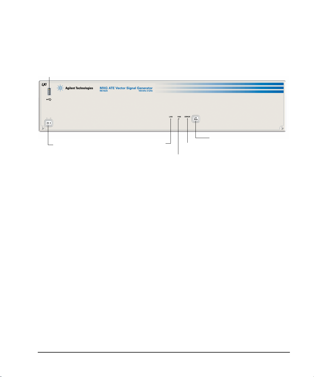
Preliminary Front Panel Overview – N5161A/62A MXG ATE
2. Power Switch and LEDs
3. LAN
6. LAN Reset
4. 1588
5. ERROR
1. Host USB
Preliminary Signal Generator Overview
Front Panel Overview – N5161A/62A MXG ATE
N5161A/62A MXG ATE Front Panel Functions
The MXG ATE is identical to an MXG with a front panel display, except that the front panel,
hardkeys and softkeys functionality are only available through SCPI commands or the Web–Enabled
MXG. For information on the Web–Enabled MXG, refer to the Installation Guide, the Programming
Guide and the SCPI Command Reference.
Functions unique to the MXG ATE:
•LAN LED(page 10).
• 1588 LED (page 10).
•ERROR LED(page 10).
• LAN Reset Hardkey (page 10).
For more information, refer to the Service Guide.
1. Host USB
Connector Type A
USB Protocol 2.0
Use this universal serial bus (USB) to connect a USB Flash Drive (UFD) for data transfer. You can
connect or disconnect a USB device without shutting down or restarting the signal generator. The
instrument also has a rear panel device USB connector (see page 17) used to remotely control the
instrument.
Agilent N5161A/62A/81A/82A/83A MXG Signal Generators User’s Guide 9
Page 24

Signal Generator Overview Preliminary
Front Panel Overview – N5161A/62A MXG ATE Preliminar
2. Power Switch and LEDs
This switch selects the standby mode or the power on mode. In the standby position, the yellow LED
lights and all signal generator functions deactivate. The signal generator remains connected to the
line power, and some power is consumed by some internal circuits. In the on position, the green LED
lights and the signal generator functions activate.
3. LAN LED
The LAN LED is used to indicate the LAN status.
• If the LED is off, the LAN is down.
• If the LED is blinking, the LAN is being configured (1.2 second duty cycle).
• A 400ms duty cycle indicates the instrument has been placed into LAN Identify mode. (Refer to
:INPut:LAN[:SET]:IDENtifier command).
• If the LED is solidly lit, the LAN is up and functional.
• If the LED fails to function, refer to the Service Guide.
4. 1588 LED
The 1588 LED indicates when the instrument is locked to an external 1588 clock.
• If the 1588 green LED is on, a 1588 signal has been detected on the TRIG OUT BNC on the rear
panel.
• If the 1588 green LED is off, no 1588 signal is detected on the TRIG OUT BNC on the rear panel.
• If the LED fails to function, refer to the Service Guide.
5. ERROR LED
The ERROR LED indicates when there are unread errors in the error queue.
• If Auto reboot is disabled, the LED will blink when an exception occurs during power up.
• If the LED fails to function, refer to the Service Guide.
6. LAN Reset Hardkey
NOTE This hardkey is enabled for fail–safe and diagnostic mode and should rarely be used.
The LAN Reset is used to access the diagnostics mode during power up.
• Refer to the SCPI Command Reference for equivalent remote commands.
• If the LAN Reset fails to function, refer to the Service Guide.
10 Agilent N5161A/62A/81A/82A/83A MXG Signal Generators User’s Guide
Page 25
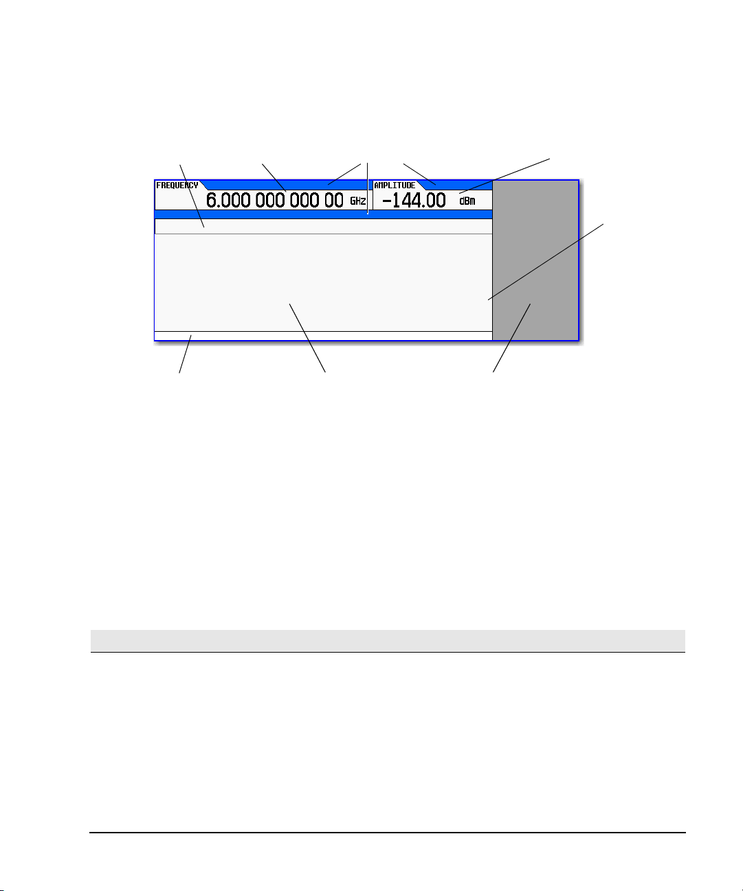
Preliminary Front Panel Display – N5181A/82A/83A MXG
5. Error Message Area
6. T ext Area
7. Softkey Label Area
4. Amplitude Area
3. Annunciators
2. Frequency Area
1. Active Function Area
Scroll Bar
If there is more
text than can be
displayed on one
screen, a scroll
bar appears here.
Use the Page Up
and Page Down
keys to scroll
through the text.
Preliminary Signal Generator Overview
Front Panel Display – N5181A/82A/83A MXG
1. Active Function Area
This area displays the currently active function. For example, if frequency is the active function, the
current frequency setting appears. If the currently active function has an increment value associated
with it, that value also appears.
2. Frequency Area
This area displays the current frequency setting.
3. Annunciators
Annunciators show the status of some of the signal generator functions, and indicate error
conditions. An annunciator position may be used by more than one annunciator; in this case, only
one of the functions sharing a given position can be active at a given time.
This annunciator appears when...
ΦM Phase modula tion is on. If you tur n frequency modulation on, the FM annunciator replaces ΦM.
ARB The ARB generator is on.
ALC OFF The ALC circuit is disabled. The UNLEVEL annunciator appears in the same position if the ALC is enabled and
AM Amplitude modulation is on.
ARMED A sweep has been initiated and the signal generator is waiting for the sweep trigger event.
ATTNHOLD The attenuator hold function is on. When this function is on, the attenuator is held at its current setting.
BBG DAC A DAC overf low is occurring, adjust the runtime scaling adjust until the BBG DAC annunciator tur ns off.
Agilent N5161A/62A/81A/82A/83A MXG Signal Generators User’s Guide 11
is unable to maintain the output level.
Another annunciator, UNLOCK, appears in the same position and has priority over the BBG DAC annunciator
(see UNLOCK, below).
Page 26

Signal Generator Overview Preliminary
Front Panel Display – N5181A/82A/83A MXG Preliminar
This annunciator appears when...
DETHTR The ALC detector heater is not up to temperature. To meet ALC specifications the heater must be at
AWGN Real Time I/Q Baseband additive white Gaussian noise is on.
DIGBUS The digital bus is in use.
DIGMOD Custom Arb waveform generator is on.
ERR An error message is placed in the error queue. This annunciator does not turn off until you either view all of
EXTREF An external frequency reference is applied.
FM Frequency modulation is on. If you turn phase modulation on, the ΦM annunciat or replaces FM.
I/Q I/Q vector modulation is on.
L The signal generator is in listener mode and is receiving information or commands over the GPIB, USB, or
M–TONE Multitone waveform generator is on.
MULT A frequency multiplier is set (see “Setting a Frequency Multiplier” on page 109).
OFFS An output offset is set (see “Setting an Output Offset” on page 107).
PN Phase noise interference is on.
PULSE Pulse modulation is on.
R The signal generator is remotely controlled over the GPIB, USB, or VXI–11/Sockets (LAN) interface. When the
REF An output reference is set (see “Setting an Output Reference” on page 108).
RF OFF The signal generator’s RF Output is not enabled.
S The signal generator has generated a service request (SRQ) over the GPIB, USB, or VXI–11/Sockets (LAN)
SWEEP The signal generator is currently sweeping in list or step mode.
SWMAN The signal generator is in manual sweep mode.
T The signal generator is in talker mode and is transmitting information over the GPIB, USB, or VXI–11/Sockets
T–TONE Two–Tone waveform generator is on.
UNLEVEL The signal generator is unable to maint ain the correct output level. This is not necessarily an indication of
UNLOCK Any of the phase locked loops cannot maintain phase lock. To determine which loop is unlocked, examine the
WINIT The signal generator is waiting for you to initiate a single sweep.
temperature.
the error messages or clear the error queue (see “Reading Error Messages” on page 74).
VXI–11/Sockets (LAN) interface.
signal generator is in remote mode, the keypad is locked out. To unlock the keypad, press Local.
interface.
(LAN) interface.
instrument failure; unleveled conditions can occur during normal operation. Another annunciator, ALC OFF,
appears in the same position when the ALC circuit is disabled (see ALC OFF, above).
error messages (see “Reading Error Messages” on page 74).
4. Amplitude Area
This area displays the current output power level setting (If the RF Output is off, this area is greyed
out).
5. Error Message Area
This area displays abbreviated error messages. If multiple messages occur, only the most recent
message remains displayed. See “Reading Error Messages” on page 74.
12 Agilent N5161A/62A/81A/82A/83A MXG Signal Generators User’s Guide
Page 27

Preliminary Blank Front Panel Display – N5161A/62A MXG ATE
Preliminary Signal Generator Overview
6. Text Area
This area displays signal generator status information, such as the modulation status, and other
information such as sweep lists and file catalogs. This area also enables you to perform functions
such as managing information (entering information, and displaying or deleting files).
7. Softkey Label Area
This area displays labels that define the function of the softkeys located immediately to the right of
the display. Softkey labels change, depending on the function selected.
Blank Front Panel Display – N5161A/62A MXG ATE
N5161A/62A MXG ATE – Web Enabled Display
The MXG ATE only has display information available through a LAN connection to the Web Server
(“11. LAN” on page 17). For more information on the Web–Enabled MXG, refer to Programming
Guide.
Annunciators
NOTE On the N5161A/62A, the following listing of annunciators are only displayed and visible
through the Web–Enabled MXG. Refer to Programming Guide, “Using the Web Browser”.
Annunciators show the status of some of the signal generator functions, and indicate error
conditions. An annunciator position may be used by more than one annunciator; in this case, only
one of the functions sharing a given position can be active at a given time.
This annunciator appears when...
ΦM Phase modula tion is on. If you tur n frequency modulation on, the FM annunciator replaces ΦM.
ARB The ARB generator is on.
ALC OFF The ALC circuit is disabled. The UNLEVEL annunciator appears in the same position if the ALC is enabled and
AM Amplitude modulation is on.
ARMED A sweep has been initiated and the signal generator is waiting for the sweep trigger event.
ATTNHOLD The attenuator hold function is on. When this function is on, the attenuator is held at its current setting.
BBG DAC A DAC overf low is occurring, adjust the runtime scaling adjust until the BBG DAC annunciator tur ns off.
DETHTR The ALC detector heater is not up to temperature. To meet ALC specifications the heater must be at
AWGN Real Time I/Q Baseband additive white Gaussian noise is on.
DIGBUS The digital bus is in use.
DIGMOD Custom Arb waveform generator is on.
ERR An error message is placed in the error queue. This annunciator does not turn off until you either view all of
EXTREF An external frequency reference is applied.
is unable to maintain the output level.
Another annunciator, UNLOCK, appears in the same position and has priority over the BBG DAC annunciator
(see UNLOCK, below).
temperature.
the error messages or clear the error queue (see “Reading Error Messages” on page 74).
Agilent N5161A/62A/81A/82A/83A MXG Signal Generators User’s Guide 13
Page 28

Signal Generator Overview Preliminary
Blank Front Panel Display – N5161A/62A MXG ATE Preliminar
This annunciator appears when...
FM Frequency modulation is on. If you turn phase modulation on, the ΦM annunciat or replaces FM.
I/Q I/Q vector modulation is on.
L The signal generator is in listener mode and is receiving information or commands over the GPIB, USB, or
M–TONE Multitone waveform generator is on.
MULT A frequency multiplier is set (see “Setting a Frequency Multiplier” on page 109).
OFFS An output offset is set (see “Setting an Output Offset” on page 107).
PN Phase noise interference is on.
PULSE Pulse modulation is on.
R The signal generator is remotely controlled over the GPIB, USB, or VXI–11/Sockets (LAN) interface. When the
REF An output reference is set (see “Setting an Output Reference” on page 108).
RF OFF The signal generator’s RF Output is not enabled.
S The signal generator has generated a service request (SRQ) over the GPIB, USB, or VXI–
SWEEP The signal generator is currently sweeping in list or step mode.
SWMAN The signal generator is in manual sweep mode.
T The signal generator is in talker mode and is transmitting information over the GPIB, USB, or VXI–11/Sockets
T–TONE Two–Tone waveform generator is on.
UNLEVEL The signal generator is unable to maint ain the correct output level. This is not necessarily an indication of
UNLOCK Any of the phase locked loops cannot maintain phase lock. To determine which loop is unlocked, examine the
WINIT The signal generator is waiting for you to initiate a single sweep.
VXI–11/Sockets (LAN) interface.
signal generator is in remote mode, the keypad is locked out. To unlock the keypad, press Local.
11/Sockets (LAN) interface.
(LAN) interface.
instrument failure; unleveled conditions can occur during normal operation. Another annunciator, ALC OFF,
appears in the same position when the ALC circuit is disabled (see ALC OFF, above).
error messages (see “Reading Error Messages” on page 74).
14 Agilent N5161A/62A/81A/82A/83A MXG Signal Generators User’s Guide
Page 29
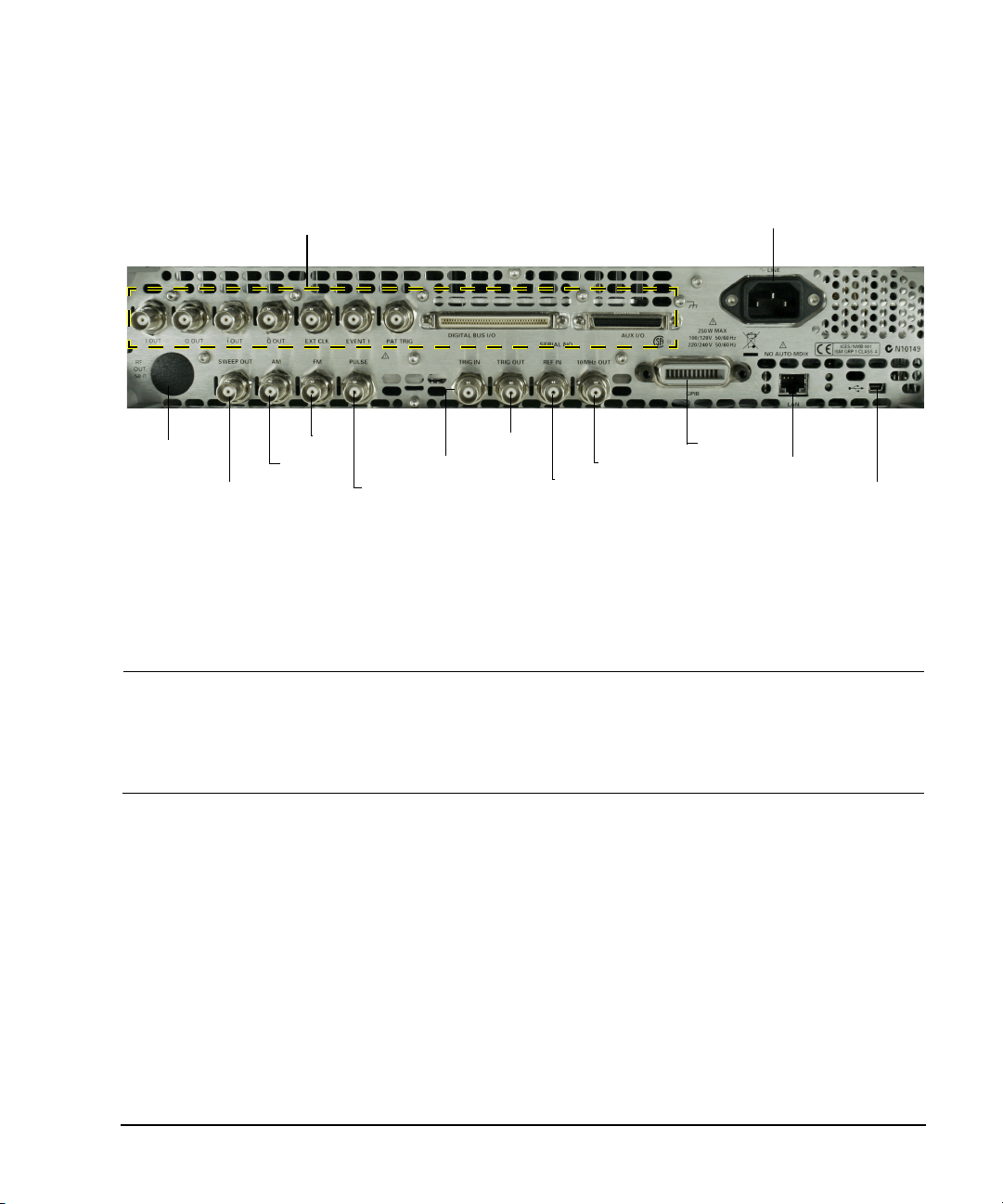
Preliminary Rear Panel Overview – N5161A/62A1/81A/82A MXG
2. SWEEP OUT
4. FM
5. PULSE
6. TRIG IN
7. TRIG OUT
8. REF IN
10. GPIB
11. LAN
12. Device USB
9. 10 MHz OUT
1. AC Power Receptacle
Option 1EM
only
See page 7
Digital Modulation Connectors (Vector Models Only) on page 18
Preliminary Signal Generator Overview
Rear Panel Overview – N5161A1/62A1/81A/82A MXG
1. AC Power Receptacle
The AC power cord receptacle accepts a three–pronged AC power cord that is supplied with the
signal generator. For details on line setting requirements and the power cord, see the
Installation Guide.
CAUTION To avoid the loss of data, GPIB settings, or current user instrument states that have not
been permanently saved to non- volatile memory, the MXG should always be powered
down either via the MXG's front panel power button or the appropriate SCPI command.
MXG's installed in rack systems and powered down with the system rack power switch
rather than the MXG's front panel switch display a Error -310 due to the MXG not being
powered down correctly.
2. SWEEP OUT
Connector female BNC
Can drive 2 kΩ.
Signal Voltage range: 0 to +10 V, regardless of sweep width
In swept mode: beginning of sweep = 0 V; end of sweep = +10 V
In CW mode: no output
This is a multiple use connector. For signal routing selections, see pages 50 and 121.
1
The N5161A and N5162A are only available with Option 1EM.
Agilent N5161A/62A/81A/82A/83A MXG Signal Generators User’s Guide 15
Impedance <1 Ω
Page 30

Signal Generator Overview Preliminary
Rear Panel Overview – N5161A/62A1/81A/82A MXG Preliminar
3. AM
Connector female BNC Impedance nominally 50 Ω
Signal An externally supplied ±1 Vp signal that produces the indicated depth.
Damage Levels 5 V
and 10 V
rms
p
4. FM
Connector female BNC Impedance nominally 50 Ω
Signal An externally supplied ±1 V
Damage Levels 5 V
and 10 V
rms
p
signal that produces the indicated deviation
p
5. PULSE
Connector female BNC Impedance nominally 50 Ω
Signal Externally supplied: +1 V = on; 0 V = off
Damage Levels 5 V
and 10 V
rms
p
6. TRIG IN
Connector female BNC Impedance high Z
Signal An externally supplied TTL or CMOS signal for triggering operations, such as point
to point in manual sweep mode or an LF sweep in external sweep mode.
Triggering can occur on either the positive or negative edge.
Damage Levels ≤ −0.5 and ≥ +5.5 V
7. TRIG OUT
Connector female BNC Impedance nominally 50 Ω
Signal A TTL signal that is high at the start of a dwell sequence, or when waiting for the point
trigger in manual sweep mode.
It is low when the dwell is over, or when the point trigger is received.
The logic polarity can be reversed.
This is a multiple use connector. For signal routing selections, see pages 50 and 121.
16 Agilent N5161A/62A/81A/82A/83A MXG Signal Generators User’s Guide
Page 31

Preliminary Rear Panel Overview – N5161A/62A1/81A/82A MXG
Preliminary Signal Generator Overview
8. REF IN
Connector female BNC Impedance nominally 50 Ω
Signal An externally supplied −3.5 to +20 dBm signal from a timebase reference that is
within ±1 ppm.
In its factory default mode, the signal generator can detect a valid reference signal at this connector
and automatically switch from internal to external reference operation. See “Presetting the Signal
Generator” on page 42. With Option 1ER (flexible reference input), you must explicitly tell the signal
generator the external reference frequency you wish to use; enter the information through the front
panel or over the remote interface.
9. 10 MHz OUT
Connector female BNC Impedance nominally 50 Ω
Signal A nominal signal level greater than 4 dBm.
10. GPIB
This connector enables communication with compatible devices such as external controllers, and is
one of three connectors available to remotely control the signal generator (see also 11. LAN and
12. Device USB).
11. LAN
The signal generator supports local area network (LAN) based communication through this connector,
which enables a LAN–connected computer to remotely program the signal generator. The LAN
interface supports LXI; it does not support auto−MDIX. The signal generator is limited to 100 meters
on a single cable (100Base–T). For more information on the LAN, refer to the Programming Guide.
12. Device USB
Connector Mini–B
USB Protocol Versio n 2. 0
Use this universal serial bus (USB) connector to connect a PC to remotely control the signal
generator.
Agilent N5161A/62A/81A/82A/83A MXG Signal Generators User’s Guide 17
Page 32

Signal Generator Overview Preliminary
I
Q
I
Q
Rear Panel Overview – N5161A/62A1/81A/82A MXG Preliminar
Digital Modulation Connectors (Vector Models Only)
I OUT, Q OUT, OUT, OUT
Connector Type: female BNC Impedance: 50 Ω
DC–coupled
Signal
I OUT The analog, in–phase component of I/Q modulation from the internal baseband generator.
Q OUT The analog, quadrature–phase component of I/Q modulation from the internal baseband
OUT
OUT
Damage Levels > 1 Vrms DC Origin Offset typically <10 mV
Output Signal Levels into a 50 Ω Load
a
Balanced signals are signals present in two separate conductors that are symmetrical relative to ground, and are opposite in polarity
(180 degrees out of phase).
generator.
Used in conjunction with the I OUT connector to provide a balanced
Used in conjunction with the Q OUT connector to provide a balanced
• 0.5 V
• 0.69 V
• 0.71 V
• Typically 1 V
, typical, corresponds to one unit length of the I/Q vector
pk
(2.84 dB), typical, maximum crest factor for peaks for π/4 DQPSK, alpha = 0.5
pk
(3.08 dB), typical, maximum crest factor for peaks for π/4 DQPSK, alpha = 0.35
pk
maximum
p–p
a
baseband stimulus.
a
baseband stimulus.
EXT CLK
Connector female BNC Impedance nominally 50 Ω
Signal An externally supplied TTL or CMOS bit clock signal where the rising edge aligns with the
beginning data bit.
The falling edge is used to clock external signals.
This signal is used with digital modulation applications.
Damage Levels < −4 and > +8 V Maximum Clock Rate 50 MHz
18 Agilent N5161A/62A/81A/82A/83A MXG Signal Generators User’s Guide
Page 33

EVENT 1
Preliminary Rear Panel Overview – N5161A/62A1/81A/82A MXG
Preliminary Signal Generator Overview
Connector
Signal A pulse that can be used to trigger the star t of a data pattern, frame, or timeslot.
Damage Levels < −4 and > +8 V
female BNC Impedance: nominally 50
Adjustable to ± one timeslot; resolution = one bit
Markers
Each Arb–based waveform point has a marker on/off condition associated with it.
Marker 1 level = +3.3 V CMOS high (positive polarity selected); –3.3 V CMOS low (negative polarity
selected).
Output on this connector occurs whenever Marker 1 is on in an Arb–based waveform (see “Using
Waveform Markers” on page 147).
Ω
PAT TRIG
Connector
Signal A TTL/CMOS low to TTL/CMOS high, or TTL/CMOS high to TTL/CMOS low edge trigger.
Damage Levels < −4 and > +8 V
female BNC Impedance: nominally 50
The input to this connector triggers the internal digital modulation pattern generator to start
a single pattern output or to stop and re–synchronize a pattern that is being continuously
output. To synchronize the trigger with the data bit clock, the trigger edge is latched, then
sampled during the falling edge of the internal data bit clock.
This is the external trigger for all ARB waveform generator triggers.
Minimum Trigger Input Pulse
Width
Minimum Trigger Delay (trigger edge to first bit of frame) = 1.5 to 2.5 bit clock periods
Ω
(high or low) = 100 ns
DIGITAL BUS I/O
This is a proprietary bus used by Agilent Technologies signal creation software. This connector is not
operational for general purpose use. Signals are present only when a signal creation software option
is installed (for details, refer to http://www.agilent.com/find/signalcreation).
NOTE The MXG’s Digital BUS I/O connector can be used for enabling operation with the Agilent
Technologies N5106A PXB MIMO Receiver Tester.
Agilent N5161A/62A/81A/82A/83A MXG Signal Generators User’s Guide 19
Page 34

Signal Generator Overview Preliminary
View looking into rear panel female 50–pin
25
1
2650
Pin 1 = Event 1
Pin 2 = Event 2
Pin 3 = Event 3
Pin 4 = Event 4
Pin 5 = Sample Rate Clock Out
Pin 6 = Patt Trig 2
Pins 7–25 = Reserved*
Pins 26–50 = Ground
*Future Capability
Event 1, 2, 3, and 4 (pins 1 − 4)
A pulse that can be used to trigger the start of a data pattern, frame, or timeslot.
Adjustable to ± one timeslot; resolution = one bit
Markers
Each Arb–based waveform point has a marker on/off condition associated with it.
Marker level = +3.3 V CMOS high (positive polarity selected); –3.3 V CMOS low (negative polarity
selected).
Patt Trig 2 (pin 6)
A TTL/CMOS low to TTL/CMOS high, or TTL/CMOS high to TTL/CMOS low edge trigger.
The input to this connector triggers the internal digital modulation pattern generator to start a single pattern output or to stop and
re–synchronize a pattern that is being continuously output.
To synchronize the trigger with the data bit clock, the trigger edge is latched, then sampled during the falling edge of the internal data bit
clock.
This is an external trigger for all ARB waveform generator triggers. Minimum pulse width = 100 ns. Damage levels: < −0.5 and > +5.5 V.
Sample Rate Clock Out (pin 5)
This output is used with an internal baseband generator. This pin relays a CMOS bit clock signal for synchronizing serial data.
Damage levels:< −0.5 and > +5.5 V.
The AUX I/O connector is a shielded .050 series board mount connector.
Rear Panel Overview – N5161A/62A1/81A/82A MXG Preliminar
AUX I/O
20 Agilent N5161A/62A/81A/82A/83A MXG Signal Generators User’s Guide
Page 35

Preliminary Rear Panel Overview – N5183A MXG
2. SWEEP OUT
3. AM
4. FM
5. PULSE
6. TRIG IN
7. TRIG OUT
8. REF IN
10. GPIB
11. LAN
12. Device USB
9. 10 MHz OU T
1. AC Power Receptacle
Option 1EM
only
See page 7
14. ALC INPUT
13. Z AXIS OUTPUT
Preliminary Signal Generator Overview
Rear Panel Overview – N5183A MXG
1. AC Power Receptacle
The AC power cord receptacle accepts a three–pronged AC power cord that is supplied with the
signal generator. For details on line setting requirements and the power cord, refer to the
Installation Guide.
CAUTION To avoid the loss of data, GPIB settings, or current user instrument states that have not
been permanently saved to non- volatile memory, the MXG should always be powered
down either via the MXG's front panel power button or the appropriate SCPI command.
MXG's installed in rack systems and powered down with the system rack power switch
rather than the MXG's front panel switch display a Error -310 due to the MXG not being
powered down correctly.
2. SWEEP OUT
Connector female BNC
Can drive 2 kΩ.
Signal Voltage range: 0 to +10 V, regardless of sweep width
In swept mode: beginning of sweep = 0 V; end of sweep = +10 V
In CW mode: no output
This is a multiple use connector. For signal routing selections, see pages 50 and 121.
Agilent N5161A/62A/81A/82A/83A MXG Signal Generators User’s Guide 21
Impedance <1 Ω
Page 36

Signal Generator Overview Preliminary
Rear Panel Overview – N5183A MXG Preliminar
3. AM
Connector female BNC Impedance nominally 50 Ω
Signal An externally supplied ±1 Vp signal that produces the indicated depth.
Damage Levels 5 V
and 10 V
rms
p
4. FM
Connector female BNC Impedance nominally 50 Ω
Signal An externally supplied ±1 Vp signal that produces the indicated deviation
Damage Levels 5 V
and 10 V
rms
p
5. PULSE
Connector female BNC Impedance nominally 50 Ω
Signal Externally supplied: +1 V = on; 0 V = off
Damage Levels 5 V
and 10 V
rms
p
6. TRIG IN
Connector female BNC Impedance high Z
Signal An externally supplied TTL or CMOS signal for triggering operations, such as point
to point in manual sweep mode or an LF sweep in external sweep mode.
Triggering can occur on either the positive or negative edge.
Damage Levels ≤ −0.5 and ≥ +5.5 V
7. TRIG OUT
Connector female BNC Impedance nominally 50 Ω
Signal A TTL signal that is high at the start of a dwell sequence, or when waiting for the point
trigger in manual sweep mode.
It is low when the dwell is over, or when the point trigger is received.
The logic polarity can be reversed.
This is a multiple use connector. For signal routing selections, see pages 50 and 121.
8. REF IN
Connector female BNC Impedance nominally 50 Ω
22 Agilent N5161A/62A/81A/82A/83A MXG Signal Generators User’s Guide
Page 37

Preliminary Rear Panel Overview – N5183A MXG
Signal An externally supplied −3.5 to +20 dBm signal from a timebase reference that is
within ±1 ppm.
In its factory default mode, the signal generator can detect a valid reference signal at this connector
and automatically switch from internal to external reference operation. See “Presetting the Signal
Generator” on page 42. With Option 1ER (flexible reference input), you must explicitly tell the signal
generator the external reference frequency you wish to use; enter the information through the front
panel or over the remote interface.
Preliminary Signal Generator Overview
9. 10 MHz OUT
Connector female BNC Impedance nominally 50 Ω
Signal A nominal signal level greater than 4 dBm.
10. GPIB
This connector enables communication with compatible devices such as external controllers, and is
one of three connectors available to remotely control the signal generator (see also 11. LAN and
12. Device USB).
11. LAN
The signal generator supports local area network (LAN) based communication through this connector,
which enables a LAN–connected computer to remotely program the signal generator. The LAN
interface supports LXI; it does not support auto−MDIX. The signal generator is limited to 100 meters
on a single cable (100Base–T). For more information on the LAN, refer to the Programming Guide.
12. Device USB
Connector Mini–B
USB Protocol Versio n 2. 0
Use this universal serial bus (USB) connector to connect a PC to remotely control the signal
generator.
13. Z AXIS OUTPUT
This female BNC connector supplies a +5 V (nominal) level during retrace and band–switch intervals
of a step or list sweep. During step or list sweep, this female BNC connector supplies a –5 V
(nominal) level when the RF frequency is at a marker frequency and intensity marker mode is on.
This signal is derived from an operational amplifier output so the load impedance should be greater
than or equal to 5 kohms.
Agilent N5161A/62A/81A/82A/83A MXG Signal Generators User’s Guide 23
Page 38

Signal Generator Overview Preliminary
Rear Panel Overview – N5183A MXG Preliminar
14. ALC INPUT
This input connector is used for negative external detector leveling.
Connector female BNC Impedance nominally 100 kΩ
Signal –0.2 mV to –0.5 V
Damage Levels –12 to 1 V
24 Agilent N5161A/62A/81A/82A/83A MXG Signal Generators User’s Guide
Page 39

2 Setting Preferences & Enabling Options
Display Settings on page 26
Front Panel Knob Resolution on page 28
Power On and Preset on page 27
Enabling an Option on page 37
GPIB Address and Remote Language on page 30
Configuring the LAN Interface on page 31
Enabling LAN Services: “Browser,” “Sockets,” “VXI–11” and “LXI–B” on page 32
Configuring the Remote Languages on page 33
User Preferences
Remote Operation
Setting Time and Date on page 28
Upgrading Firmware on page 29
Getting Started With LXIon page 115
Hardware Assembly Installation and Removal Softkeys on page 39
Reference Oscillator Tune on page 29
NOTE For the N5161A/62A MXG ATE the softkey menus and features mentioned in this guide are
only available through the Web–Enabled MXG or SCPI commands. For information on the
Web-Enabled MXG, refer to the Installation Guide, the Programming Guide, and to the SCPI
Command Reference.
The Utility menu provides access to both user and remote operation preferences, and to the menus in
which you can enable instrument options.
Agilent N5161A/62A/81A/82A/83A MXG Signal Generators User’s Guide 25
Page 40

Setting Preferences & Enabling Options Preliminary
Range:15 to 100
Range: 35 to 55
Range: 1to 12 hours, in 1 hour increments
Light Only: turns the display light off, leaving the text visible at a low intensity.
Light & Text: turns the display light and the text off.
If the display remains unchanged for long periods of time, use this mode to
prevent the text from burning the display.
When on, commands executed through
the remote control bus update the signal
generator display accordingly.
Bright without color
Utility > Display
See also, Using the Secure Display (Option 006 Only) on page
For details on each key, use key help
as described on page 42.
page 304
Dark text on a light
background.
Light text on a dark
background.
User Preferences Preliminary
User Preferences
From the Utility menu, you can set the following user preferences:
• Display Settings, below
• Power On and Preset on page 27
• Front Panel Knob Resolution on page 28
Display Settings
NOTE With both brightness and contrast set to minimum, the display may be too dark to see the
26 Agilent N5161A/62A/81A/82A/83A MXG Signal Generators User’s Guide
softkeys. If this happens, use the figure above to locate the brightness and contrast softkeys
and adjust their values so that you can see the display.
Page 41

Power On and Preset
Select the GPIB language desired after a preset.
See also, the Programming Guide and the SCPI Command
Reference.
Utility > Power On/Preset >
Restores persistent settings
(those unaffected by a power
cycle*, preset, or recall)
to their factory defaults.
Availabl e on ly w h en 8 64 8 i s either the select ed pr es etlanguage or
the selected remote language (see page 30).
*
Caution
To avoid the loss of data, GPIB settings, or current user instrument states that have not been permanently saved to
non-volatile memory, the MXG should always be powered down either via the MXG's front panel power button or the
appropriate SCPI command. MXG's installed in rack systems and powered down with the system rack power switch
rather than the MXG's front panel switch display a Error -310 due to the MXG not being powered down correctly.
Note
To define a user preset, set the instrument up as desired and press User Preset > Save User Preset.
Preliminary Setting Preferences & Enabling Options
Preliminary User Preferences
Agilent N5161A/62A/81A/82A/83A MXG Signal Generators User’s Guide 27
Page 42

Setting Preferences & Enabling Options Preliminary
Makes the increment value of the current function the active entry.
Utility >
Instrument Adjustments >
The increment value and the step/knob ratio determine how much each
turn of the knob changes the active function value.
For example, if the increment value of the active function is 10 dB and the
step/knob ratio is 50 to 1, each turn of the knob changes the active
function by 0.2 dB (1/50th of 10 dB).
To change the amount for each turn of the knob, modify the increment
value, the step/knob ratio, or both.
For details on each key, use key help
as described on page42.
page 29.
page 28.
Executes the Alc Modulator Bias Adjustment. When using
the ALC in open loop mode, this compensates for open loop
power drift due to temperature and humidity.
SCPI Commands:
:CALibration:ALC:MODulator:BIAS
Utility >
Instrument Adjustments>
CAUTION
Original time/date reference point
Time
New time/date reference point
User Preferences Preliminary
Front Panel Knob Resolution
Setting Time and Date
The signal generator’s firmware tracks the
time and date, and uses the latest time
and date as its time/date reference point.
Setting the Time or Date Forward
If you set the time or date forward, be aware that you are using up any installed time–based licenses,
and that you are resetting the signal generator’s time/date reference point. When you set a new time
or date that is later than the signal generator’s current reference point, that date becomes the new
reference point. If you then set the date back, you run the risk described in the next section.
Setting the Time or Date Backward
When you set the time back, the signal generator notes that the time has moved back from the
reference point. If you set the time back more a few hours, you disable the signal generator’s ability
to use time–based licenses, even if there is no license installed at the time that you set the time
28 Agilent N5161A/62A/81A/82A/83A MXG Signal Generators User’s Guide
Changing the time or date can
adversely affect the signal
generator’s ability to use time−based
licenses, even if a time−based
license is not installed.
Page 43

Preliminary Setting Preferences & Enabling Options
Tunes the internal VCTXCO oscillator frequency.
The user value offsets the factory tuned value (the value is added to the
factory calibrated DAC value). The tune value of 0 sets the factory
calibrated value.
The range; –8192 to 8192, can be set by using the front panel keypad,
knob or remote command.
For details on each key, use key help
as described on page 42.
See also the SCPI Command Reference.
Utility > Instrument Adjustments >
Preliminary Upgrading Firmware
back. In this case, you can re- enable the signal generator’s ability to use time–based licenses by
moving the clock forward to the original time or simply waiting that length of time.
Reference Oscillator Tune
Upgrading Firmware
For information on new firmware releases, go to http://www.agilent.com/find/upgradeassistant.
Agilent N5161A/62A/81A/82A/83A MXG Signal Generators User’s Guide 29
Page 44

Setting Preferences & Enabling Options Preliminary
page 31
page 32
NOTES
USB is also available. It is not shown in the menu because it requires no configuration.
For details on using the instrument remotely, see the Programming Guide.
Select the desired language.
This setting is not persistent and is cleared by performing a
instrument Preset. In most cases, it is best to use Utility >
Power On/Preset > Language for a permanent language
change. See page 33.
For details on each key, use key help as described on page 42.
Remote Operation Preferences Preliminary
Remote Operation Preferences
For details on operating the signal generator remotely, refer to the Programming Guide.
GPIB Address and Remote Language
30 Agilent N5161A/62A/81A/82A/83A MXG Signal Generators User’s Guide
Page 45

NOTES
Use a 100Base–T LAN
cable to connect the signal generator to the LAN.
Use a crossover cable to connect the signal
generator directly to a PC.
For details on using the instrument remotely,
refer to the Programming Guide and to
www.agilent.com and sea rch on F A Qs: Hardware
Configurations and Installation for the Agilent
MXG.
Utility > I/O Config
Listed in the
Programming Guide
For details on each key, use key help as described on page 42.
page 32.
Configuring the LAN Interface
Preliminary Setting Preferences & Enabling Options
Preliminary Remote Operation Preferences
Agilent N5161A/62A/81A/82A/83A MXG Signal Generators User’s Guide 31
Page 46

Setting Preferences & Enabling Options Preliminary
Enable remote
(browser) access to the
instrument’s file system.
Use a browser to control
the signal generator.
Utility > I/O Config
For details on each key, use key help
as described on page42.
License Manager Server
(On) allows updates of the
instrument licenses, disable
for additional instrument
security.
For more information ref er to
the Programming Guide.
page 115.
Remote Operation Preferences Preliminary
Enabling LAN Services: “Browser,” “Sockets,” “VXI–11” and “LXI–B”
1
1
LXI–B is only available on instruments with serial prefixes >US/MY/SG4818.
32 Agilent N5161A/62A/81A/82A/83A MXG Signal Generators User’s Guide
Page 47

Configuring the Remote Languages
Utility > I/O Config
For details on each key, use key help
as described on page42.
Select the desired Remote language.
Refer to the SCPI Command Reference.
Figure 2-1 N5161A/62A/81A/82A
Preliminary Setting Preferences & Enabling Options
Preliminary Remote Operation Preferences
Agilent N5161A/62A/81A/82A/83A MXG Signal Generators User’s Guide 33
Page 48

Setting Preferences & Enabling Options Preliminary
Select the desired Remote language.
Utility > I/O Config >
For details on each key, use key help
as described on page 42.
Refer to the SCPI Command Referen ce.
Remote Operation Preferences Preliminary
Figure 2-2 N5183A
34 Agilent N5161A/62A/81A/82A/83A MXG Signal Generators User’s Guide
Page 49
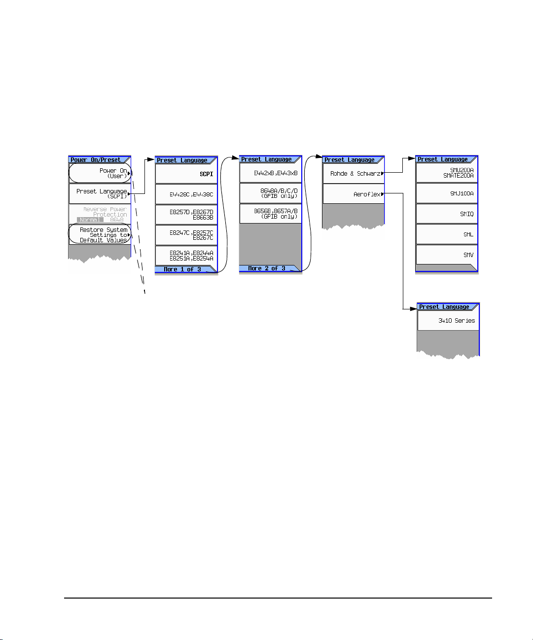
Configuring the Preset Languages
Utility> Power On/Preset
For details on each key, use key help
as described on page42.
Select the desired Remote language.
page 27
Refer to the SCPI Command Referen ce.
Figure 2-3 N5161A/62A/81A/82A
Preliminary Setting Preferences & Enabling Options
Preliminary Remote Operation Preferences
Agilent N5161A/62A/81A/82A/83A MXG Signal Generators User’s Guide 35
Page 50

Setting Preferences & Enabling Options Preliminary
Select the desired Remote language.Utility > Power On/Preset
For details on each key, use key help
as described on page 42.
page 27
Refer to the SCPI Command Reference.
Remote Operation Preferences Preliminary
Figure 2-4 N5183A
36 Agilent N5161A/62A/81A/82A/83A MXG Signal Generators User’s Guide
Page 51

Utility >
Instrument Info
Service Software Licenses
Waveform licenses from some
Instrument options appear
here. A check mark means that
an option is enabled.
For details on each key, use key help
as described on page42.
Signal Studio applications appear here.
appear here.
Preliminary Setting Preferences & Enabling Options
Preliminary Enabling an Option
Enabling an Option
There are two ways to enable an option:
• Use the License Manager software utility:
1. Run the utility and follow the prompts.
2. Download the utility from www.agilent.com/find/LicenseManager and select license (.lic) files
from an external USB Flash Drive (UFD).
• Use SCPI commands, as described in the Programming Guide.
Viewing Options and Licenses
Agilent N5161A/62A/81A/82A/83A MXG Signal Generators User’s Guide 37
Page 52

Setting Preferences & Enabling Options Preliminary
Utility >
Instrument Info
Service Software Licenses
Waveform licenses from some
Instrument options appear
here. A check mark means that
an option is enabled.
For details on each key, use key help
as described on page42.
Signal Studio applications appear here.
appear here.
Service Menu Preliminary
Service Menu
There are two ways to enable an option:
• Use the License Manager software utility:
• Use SCPI commands, as described in the Programming Guide.
Viewing Options and Licenses
1. Run the utility and follow the prompts.
2. Download the utility from www.agilent.com/find/LicenseManager and select license (.lic) files
from an external USB Flash Drive (UFD).
38 Agilent N5161A/62A/81A/82A/83A MXG Signal Generators User’s Guide
Page 53
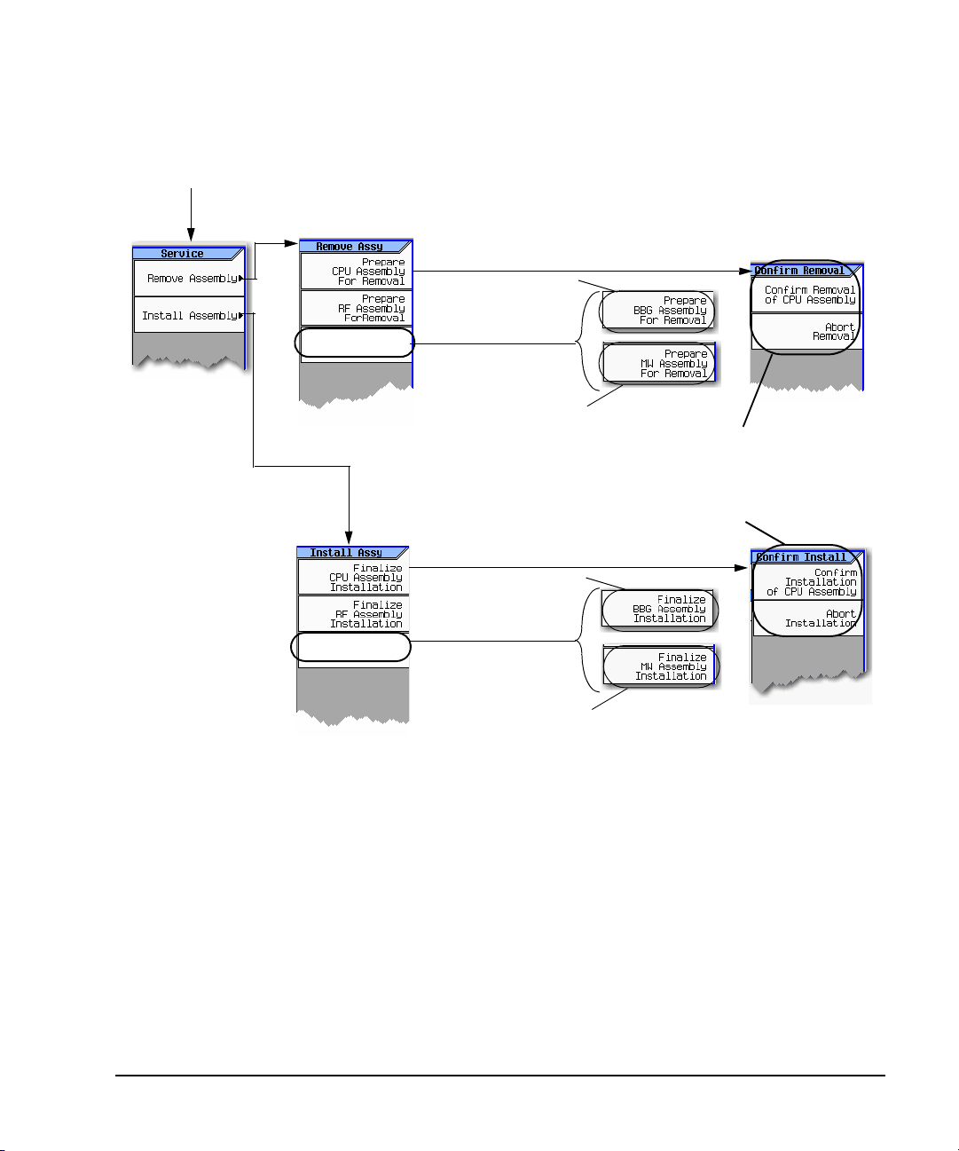
Hardware Assembly Installation and Removal Softkeys
N5162A/82A only
N5183A only
Whether a softkey is available
depends on the model of MXG.
Note: When pressed, a Confirm Removal menu (similar to the
one shown here for the CPU assembly) is opened for the RF,
BBG, and MW assemblies too.
Whether a softkey is available
depends on the model of MXG.
N5162A/82A only
N5183A only
Note: When pressed, a Confirm Install menu (similar to the one
shown here for the CPU assembly) is opened for the RF, BBG,
and MW assemblies too.
Utility > More 2 of 2 > Service
For details on each key, use key help
as described on page 42.
Note:
Each Remove Assembly softke y (CPU/RF/BBG/MW) when enabled will display a message in the lower left quadrant of display indicating
assembly prepared for removal or removal has been aborted.
Each Install Assembly softkey, when enabled will display a message in the lower left quadrant of display indicating assembly prepared for
installation or installation has been aborted.
Refer also, to the Service Guide.
Preliminary Setting Preferences & Enabling Options
Preliminary Service Menu
Agilent N5161A/62A/81A/82A/83A MXG Signal Generators User’s Guide 39
Page 54

Setting Preferences & Enabling Options Preliminary
Service Menu Preliminary
40 Agilent N5161A/62A/81A/82A/83A MXG Signal Generators User’s Guide
Page 55

3 Basic Operation
NOTE For the N5161A/62A the softkey menus and features mentioned in this guide are only
This chapter introduces fundamental front panel operation. For information on remote operation,
refer to the Programming Guide.
• Presetting the Signal Generator on page 42
• Viewing Key Descriptions on page 42
• Entering and Editing Numbers and Text on page 43
• Setting Frequency and Power (Amplitude) on page 45
• Setting ALC Bandwidth Control on page 47
• Configuring a Swept Output on page 48
• Modulating the Carrier Signal on page 60
• Wo rking w i t h F i l es on page 62
• Reading Error Messages on page 74
available through the Web–Enabled MXG or SCPI commands. For information on the
Web- Enabled MXG, refer to the Installation Guide, the Programming Guide, and the SCPI
Command Reference.
Agilent N5161A/62A/81A/82A/83A MXG Signal Generators User’s Guide 41
Page 56

Basic Operation Preliminary
To return the signal generator to a known state, press either Preset or User Preset.
Preset is the factory preset; User Preset is a custom preset** (see also, page 27).
To reset persistent settings (those unaffected by preset, user preset, or power cycle*),
press: Utility > Power On/Preset > Restore System Defau lts.
*Caution
To avoid the loss of data, GPIB settings, or current user instrument states that have not been permanently saved to
non-volatile memory, the MXG should always be powered down either via the MXG's front panel power button or the
appropriate SCPI command. MXG's installed in rack systems and powered down with the system rack power switch
rather than the MXG's front panel switch display a Error -310 due to the MXG not being powered down correctly.
**
You can create more than one user preset by giving each saved state file a different name (see Figure 3-11 on page 72).
The Help hardkey enables you to display a description of any hardkey or softkey.
To display help text:
1. Press Help.
2. Press the desired key.
The help displays and the key’s normal function does not execute.
Presetting the Signal Generator Preliminary
Presetting the Signal Generator
Viewing Key Descriptions
42 Agilent N5161A/62A/81A/82A/83A MXG Signal Generators User’s Guide
Page 57

Entering and Editing Numbers and Text
Up/down arrow keys increase/decrease a selected (highlighted) numeric value, and move the cursor vertically.
To specify a negative value, enter the
negative sign either before or after
Backspace moves the cursor to the left,
deleting characters as it goes.
Left/right arrow keys move the cursor horizontally.
Page up/down keys move tables of data up and down within the display area.
Use the number keys and decimal point to enter numeric data.
Note: Rotating the knob increases or
decreases a numeric value, changes a
highlighted digit or character, or steps
through lists or items in a row.
See also, Front Panel Knob Resolution on page 19
the numeric value (this key is a toggle).
For details on each key, see page 42.
Use the Select hardkey to choose part of an entry, as when entering alpha
characters. In some menus, the
Select key also acts as a terminator, and is
equivalent to the
Enter softkey.
to move the cursor
within the active value
rather than within the
alpha table, turn the
alpha table off.
Add/edit comments for saved
instrument state files (see page 69).
Note: File names are limited to 25 characters.
Entering Numbers and Moving the Cursor
Preliminary Entering and Editing Numbers and Text
Preliminary Basic Operation
Entering Alpha Characters
Data entry softkeys appear in
various menus. If their meaning
is not clear in context, use the
help key (described on page 42)
to display an explanation. Use
the softkey next to the alpha
table for help on the table.
Selecting data that accepts
alpha characters, displays one of
the menus shown at right.
Use the arrow keys or knob to
highlight the desired letter, then
press the Select hardkey (or the
softkey next to the alpha table).
To correct errors, use Bk Sp or
Clear Text.
To terminate the entry, press the Enter softkey.
A subset of this menu appears for hexadecimal characters. The character menu displays only the
letters A through F (use the numeric keypad for other values).
Agilent N5161A/62A/81A/82A/83A MXG Signal Generators User’s Guide 43
Page 58

Basic Operation Preliminary
Cursor
T a ble Editor Softkeys
T a ble Editor Name
Table Items
Displays the active item as you edit it.
Highlighting indicates the selected item. To make this the active (editable)
item, either press Select, or simply enter the desired value.
Table items are also
called data fields.
Used to load, navigate, modify, and
store table item values. For details
on each key, use the key help:
Press the Help hardkey and then
the desired key.
Active Function Area
Current / Total Number of Pages
Indicates that
another menu
is available; to
display the
second menu,
press More.
(vector models only)
Entering and Editing Numbers and Text Preliminary
Example: Using a Table Editor
Table editors simplify configuration tasks. The following procedure describes basic table editor
functionality using the List Mode Values table editor.
1. Preset the signal generator: Press Preset.
2. Open the table editor: Press Sweep > More > Configure List Sweep.
The signal generator displays the editor shown in the following figure.
3. Highlight the desired item: use the arrow keys or the knob to move the cursor.
4. (Optional) Display the selected item in the active function area: Press Select.
5. Modify the value:
• If the value is displayed in the active function area, use the knob, arrow keys, or numeric
keypad to modify the value.
• If the value is not displayed in the active function area, use the numeric keypad to enter the
desired value (which then appears in the active function area).
6. Terminate the entry:
• If available, press the desired units.
• If units are not displayed, press either Enter (if available) or Select.
The modified item is displayed in the table.
44 Agilent N5161A/62A/81A/82A/83A MXG Signal Generators User’s Guide
Page 59

Setting Frequency and Power (Amplitude)
page 107
To display the next menu, press More.
For details on each key, use key help
as described on page 42.
page 46
Refer to the SCPI Command
Reference.
Opens the
Atten/ALC
Control
menu.
Enables the optimize signal-to-noise ratio state (Optimize S/N) On or Off.
The optimize signal–to–noise softkey changes the attenuator and alc setting to provide optimal
signal–to–noise performance; it does not change the RF output power.
Caution: When the optimize signal-to-noise ratio state is enabled, some increased levels of
harmonic distortion can occur. This increased harmonic distortion could degrade ACPR and EVM.
Note: This mode is mutually exclusive with attenuator hold (Atten Hold), and any modulation type. A
settings conflict error will be generated if attentuator hold or any modulation is activated when
optimize signal–to–noise is active (On).
page 47
This softkey sets a user
determined maximum
power level on the
instrument that is
persistent.
Enables the
User Power
Max softkey.
page 88
In Amplitude mode, this menu is
automatically displayed when entering
a numeric value with the front panel
keypad.
In Frequency mode, this menu is
automatically displayed when entering
a numeric value with the front panel
keypad.
Figure 3-1 Frequency and Amplitude Softkeys
Preliminary Setting Frequency and Power (Amplitude)
Preliminary Basic Operation
Agilent N5161A/62A/81A/82A/83A MXG Signal Generators User’s Guide 45
Page 60

Basic Operation Preliminary
For details on each key, use key help as described on page42.
Range: 1 to 50 MHz
For guaranteed operation below 2 MHz, select Narrow bandwidth; in Wide bandwidth,
operation using frequencies below 2 MHz is not guaranteed.
Freq > More
Figure 3-2 illustrates the better close in phase noise of the wide bandwidth mode. If the
external reference you are using is noisy or spurious, use the narrow bandwidth mode.
With Wide bandwidth selected, If you select a frequency less than 2 MHz, the signal
generator displays a warning message.
uses the signal generator’s internal reference oscillator.
uses the REF IN connecto r to ge t it’s Frequency Reference. Note: An
error screen is displayed if the reference is not connected or is tuned
to the wrong frequency.
uses the signal generator’s internal reference unless a signal is
present at the rearpanel REF IN connector. If an external signal is
present, that signal is used as the reference.
Setting Frequency and Power (Amplitude) Preliminary
Example: Configuring a 700 MHz, −20 dBm Continuous Wave Output
1. Preset the signal generator.
The signal generator displays its maximum specified frequency and minimum power level (the
front panel display areas are shown on page 11).
2. Set the frequency to 700 MHz: Press Freq > 700 > MHz.
The signal generator displays 700 MHz in both the FREQUENCY area of the display and the active
entry area.
3. Set the amplitude to −20 dBm: Press Amptd > –20 > dBm.
The display changes to −20 dBm in the AMPLITUDE area of the display, and the amplitude value
becomes the active entry. Amplitude remains the active function until you press another function
key.
4. Turn on the RF Output: Press RF On/Off.
The RF Output LED lights, and a 700 MHz, −20 dBm CW signal is available at the RF OUTPUT
connector.
Using an External Reference Oscillator
When using an external reference, you can select either narrow or wide bandwidth mode.
46 Agilent N5161A/62A/81A/82A/83A MXG Signal Generators User’s Guide
Page 61

Figure 3-2 Using an External Reference Oscillator
To display the next menu, press
More.
For details on each key, use key help
as described on page42.
Refer to the SCPI Command
Reference.
Enables the
automatic
ALC
bandwidth
mode
(Auto).
Disabling the
Auto ALC
mode, sets
the
bandwidth to
200 Hz.
Preliminary Setting ALC Bandwidth Control
Preliminary Basic Operation
Setting ALC Bandwidth Control
Figure 3-3 Amplitude Softkeys
Agilent N5161A/62A/81A/82A/83A MXG Signal Generators User’s Guide 47
Page 62

Basic Operation Preliminary
Configuring a Swept Output Preliminary
Configuring a Swept Output
The signal generator has two methods of sweeping through a set of frequency and amplitude points:
Step sweep (page 51) provides a linear or logarithmic progression from one selected frequency,
amplitude, or both, to another, pausing at linearly or logarithmically spaced points (steps) along the
sweep. The sweep can progress forward, backward, or manually.
List sweep (page 56) enables you to enter frequencies and amplitudes at unequal intervals, in
nonlinear ascending, descending, or random order. List sweep also enables you to copy the current
step sweep values, include an Arb waveform in a sweep (on a vector instrument), and save list sweep
data in the file catalog (page 67).
48 Agilent N5161A/62A/81A/82A/83A MXG Signal Generators User’s Guide
Page 63

Figure 3-4 Sweep Softkeys
Sweep without waiting for
a trigger at each point.
Point Trigger pau ses for the dwel l
time prior to the first sweep. See
page 111.
Apply a TTL/CMOS signal to the
Trigger In connector.
Periodically issue a trigger event to
whatever selects it as a source.
Using timer trigger with single
sweep results in a delay prior to the
first sweep. See page 111.
Trigger on a remote command.
Down sweeps from
stop to start
frequency/amplitude.
Up sweeps from start
to stop
frequency/amplitude.
page 56
The selected sweep type determines the displayed parameter.
Selecting step sweep also displays the step spacing (Lin or Log).
On vector models:
Available when
Sweep Type= List
page 60
During a sweep, the swept parameter (frequency, amplitude, or both) turns grey and changes as the parameter sweeps.
Progress Bar: Note that very fast sweeps
can appear to sweep randomly or
backward.
page 50
For details on each key, use key help as described on page 42.
page 51
Does not effect
Sweep Out BNC
or TRig Out BNC
signals that are
routed as Source
Settled (See
page 50).
Sets the trigger
source to any
enabled LXI trigger.
input event.
Sets an LXI Alarm
during a sweep or
point trigger.
Configure the alarm
through SCPI only.
Preliminary Configuring a Swept Output
Preliminary Basic Operation
Agilent N5161A/62A/81A/82A/83A MXG Signal Generators User’s Guide 49
Page 64

Basic Operation Preliminary
Routes Step or
List Sweep
These softkeys are
only available for
the N5162A/82A
with a BBG .
Source Settled
is not effected
by Trig Out
Polarity Neg
Pos softkey
selections (see
page 49).
N5161A1/62A1/81A/8
2A Only
N5183A Only
N5183A only:
Optimizes the
N5183A 10V
Step Sweep
(Sweep Out)
BNC setup with
the 8757D.*
* The N5183A
signal generator
does not supp ort
the 8757 system
interface.
For details on each key, use key help
as described on page 42.
1
The N5161A and N5162A are identical to an MXG with a front panel display, except that the front
panel, hardkeys and softkeys functionality are only available through SCPI commands or the
Web–Enabled MXG. For information on the Web-Enabled MXG, refer to the Installation Guide, the
Programming Guide and the SCPI Command Reference.
page 116
Routes non
Step or List
Sweep signals
(i.e. SCPI
command
development.
Routes Step or
List Sweep
signals.
Routes non Step
or List Sweep
signals (i.e. SCPI
command
development.
These softkeys are
only available on a
N5162A/82A with a
BBG.
This softkey controls
the Event 2 marker
control
(N5162A1/82A only)
on the rear panel
Configuring a Swept Output Preliminary
Routing Signals
Sweep > More > More > Route Connectors
50 Agilent N5161A/62A/81A/82A/83A MXG Signal Generators User’s Guide
Page 65
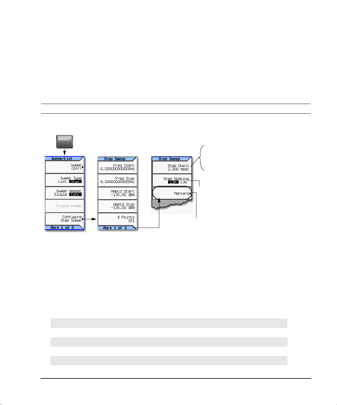
Preliminary Configuring a Swept Output
Dwell Time = the time that the signal is settled and you can make
a measurement before the sweep moves to the next point.
(Point to po int tim e is the sum of the value set for the dwell plus
processing time, switching time, and settling time.)
Lin = steps equally spaced over the sweep; the output changes
linearly.
Log = step spacing increases logarithmically over the sweep; the
output changes exponentially.
Step Sweep and List Sweep dwell times are set indep enden tly.
For details on each key, use key help
as described on page 42.
N5183A Only: Opens the frequency marker menu. See page 54.
(The N5183A does not support Agilent 8757 the system interface.)
Preliminary Basic Operation
Step Sweep
Step sweep provides a linear or logarithmic progression from one selected frequency, or amplitude, or
both, to another, pausing at linearly or logarithmically spaced points (steps) along the sweep. The
sweep can progress forward, backward, or be changed manually.
The N5183A allows you to use step sweep along with the frequency markers on instruments during
measurements (refer to “Using Frequency Markers (N5183A Only)” on page 54).
NOTE The N5183A does not support the 8757 system interface.
Figure 3-5 Sweep Softkeys
Example: Configuring a Continuous, Linear Step Sweep
Output: A signal that continuously sweeps from 500 to 600 MHz and from −20 to 0 dBm, with a
dwell time of 500 ms at each of six equally−spaced points.
1. Preset the instrument and open the Sweep/List menu: Press Preset > SWEEP.
Because continuous is the default sweep repeat selection, and linear is the default step spacing
selection, you do not need to set these parameters.
2. Open the step sweep menu: Press Configure Step Sweep.
3. Set the following parameters:
Start frequency 500 MHz: Press Freq Start > 500 > MHz
Stop frequency 600 MHz: Press Freq Stop > 600 > MHz
Amplitude at the beginning of the sweep, −20 dBm: Press Amptd Start >
Amplitude at the end of the sweep, 0 dBm: Press Amptd Stop > 0 > dBm.
6 sweep points: Press # Points > 6 > Enter
Dwell time at each point, 500 milliseconds: Press More > Step Dwell > 500 > msec
Agilent N5161A/62A/81A/82A/83A MXG Signal Generators User’s Guide 51
−20 > dBm
Page 66

Basic Operation Preliminary
N5183A
MXG Microwave Signal
Generator
8757D
Scalar
Network
Analyzer*
*The N5183A signal generator is not compatible with the 8757 system interface.
Configuring a Swept Output Preliminary
4. Sweep both frequency and amplitude: Press Return > Return > Sweep > Freq Off On > Amptd Off On.
A continuous sweep begins, from the start frequency/amplitude to the stop frequency/amplitude.
The SWEEP annunciator displays, and sweep progress is shown in the frequency display, the
amplitude display, and the progress bar.
5. Turn the RF output on: Press RF On/Off.
The RF LED lights, and the continuous sweep is available at the RF Output connector.
Using Basic Step Sweep Functions
This procedure demonstrates the following task:
• “Configuring a Frequency Sweep (N5183A only)” on page 52
Configuring a Frequency Sweep (N5183A only)
For this example, we are going to set a step sweep using the N5183A, over a frequency range of 7.5
to 10.0 GHz, using a band–pass filter as our device under test, and display that response on a 8757D
Scalar Analyzer.
1. Set up the equipment as shown in Figure 3- 6.
NOTE The N5183A signal generator does not support the 8757 system interface.
Scalar analyzer settings must match the signal generator’s settings.
Figure 3-6 Equipment Setup
52 Agilent N5161A/62A/81A/82A/83A MXG Signal Generators User’s Guide
Page 67

Preliminary Configuring a Swept Output
Preliminary Basic Operation
2. Turn on both the 8757D and the N5183A.
3. On the 8757D:
a. Press SYSTEM > MORE > SWEEP MODE and verify that the SYSINTF softkey is set to OFF.
b. Press SYSTEM > MORE > DC
c. Press SYSTEM > Freq LABELS > START FREQ > 7.5 GHz
d. Press SYSTEM > FREQ LABELS > STOP FREQ > 10.0 GHz
e. Press SYSTEM > TRACE # POINTS > 801
4. On the N5183A:
a. Change the connector routing to 8757D System, enabling the N5183A to provide a sweep out
to the 8757D during Step sweep operations. Press Sweep > More > More > Route Connectors >
Route to Sweep Out BNC > Sweep Out (Optimized for 8757D System).
b. Press Sweep > Configure Step Sweep > # Points > 801
c. Press Sweep > Configure Step Sweep > Freq Stop > 10.0 GHz
d. Press Sweep > Configure Step Sweep > Freq Start > 7.5 GHz
e. Press Sweep > Sweep > Freq On Off set to On
NOTE During swept RF output, the FREQUENCY and/or AMPLITUDE areas of the signal generator’s
display are greyed out, depending on what is being swept. In this case, since frequency is
being swept the FREQUENCY area of the display is greyed out.
5. On the 8757D: Adjust the settings for start and stop frequency response of the device under test
(DUT) so it is clearly seen on the 8757D display.
You may need to rescale the response on the 8757D for a more accurate evaluation of the
amplitude. Figure 3- 7 on page 54 shows an example of a bandpass filter response.
Agilent N5161A/62A/81A/82A/83A MXG Signal Generators User’s Guide 53
Page 68

Basic Operation Preliminary
Configuring a Swept Output Preliminary
Figure 3-7 Bandpass Filter Response on 8757D
Using Frequency Markers (N5183A Only)
In step sweep mode, you can use the N5183A to create up to 20 frequency markers to display on
your measurement equipment.
NOTE The N5183A does not support the 8757 system interface.
54 Agilent N5161A/62A/81A/82A/83A MXG Signal Generators User’s Guide
Page 69

Figure 3-8 Frequency Marker Softkeys
Sweep > Configure Step Sweep >
More > Markers
Sets the frequency for the
marker number highlighted.
Up to 20 frequency markers
can be set.
Enables the selected
frequency marker.
Selects the highlighted marker
as the frequency reference
marker for the rest of the
frequency markers.
If the Delta Ref Set softkey
has been pressed, this softkey
enables the Marker Delta
function and uses the Ref
marker as t he frequency
marker reference for the other
markers.
Sets the marker’s amplitude
value displayed on the
instrument (Range: –10 dB to
10 dB).
For details on each key, use key help
as described on page42.
Sets the center frequency of
the sweep to the value of the
highlight ed marker (row).
Sets the start frequency of the
sweep to the value of marker
1 (M1) and the stop frequency
to the value of marker 2 (M2).
Preliminary Configuring a Swept Output
Preliminary Basic Operation
Agilent N5161A/62A/81A/82A/83A MXG Signal Generators User’s Guide 55
Page 70

Basic Operation Preliminary
see page 57
The selected sweep determines which dwell time the signal generator uses. Step Sweep dwell
time is the same at each point; List Sweep dwell time can be different at each point.
Dwell Time = the time that the signal is settled and you can make a measurement before the
sweep moves to the next point.
Point–to–Point Time = the sum of the value set for the dwell plus processing time, switching
time, and settling time.
Each line defines the
corresponding point in
the sweep. For example,
line 1 defines point 1.
page 51
Available only on vector models,
and
only when Sweep Type = List.
Displays the selected
sweep type parameters
(see page 57)
Vector models only
page 50
For details on each key, use key help
as described on page42.
Available only when
waveform entry is selected
Configuring a Swept Output Preliminary
List Sweep
List sweep enables you to enter frequencies and amplitudes at unequal intervals in nonlinear
ascending, descending, or random order. List sweep also enables you to copy the current step sweep
values, include a waveform in a sweep (on a vector instrument), and save list sweep data in the file
catalog (page 67). Dwell time is editable at each point. For fastest switching speeds, use list sweep.
Figure 3-9 List Sweep Configuration Softkeys and Display
56 Agilent N5161A/62A/81A/82A/83A MXG Signal Generators User’s Guide
Page 71

Preliminary Configuring a Swept Output
Vector Mo d e l s :
Presetting the list clears
any previously selected
waveforms.
For information on
selecting a list sweep
waveform, see Example:
Editing List Sweep
Poin ts on page 58.
Waveforms are available
only on vector models.
Preliminary Basic Operation
Example: Configuring a List Sweep Using Step Sweep Data
1. Set up the desired step sweep, but do not turn the sweep on. This example uses the step sweep
configured on page 51.
2. In the SWEEP menu, change the sweep type to list:
Press SWEEP > Sweep Type List Step to highlight List.
The display shows sweep list parameters, as shown below.
3. Open the List Sweep menu: Press More > Configure List Sweep.
4. Clear any previously set values from the menu and load the points defined in the step sweep into
the list: Press More > Preset List > Preset with Step Sweep > Confirm Preset.
The display updates with the values loaded from the step sweep, as shown.
5. Sweep frequency and amplitude: Press SWEEP (hardkey) > Sweep > Freq Off On > Amptd Off On.
Setting the sweep turns on the sweep function; a continuous sweep begins. On the display, the
SWEEP annunciator appears, and the progress bar shows the progression of the sweep.
6. If not already on, turn the RF output on: Press RF On/Off.
The RF Output LED lights, and a continuous sweep is available at the RF OUTPUT connector.
Agilent N5161A/62A/81A/82A/83A MXG Signal Generators User’s Guide 57
Page 72

Basic Operation Preliminary
Either select a waveform,
or
select no modulation.
Configuring a Swept Output Preliminary
Example: Editing List Sweep Points
If you are not familiar with table editors, refer to page 44.
1. Create the desired list sweep. This example uses the list sweep created in the previous example.
2. If sweep is on, turn it off. Editing list sweep parameters with sweep on can generate an error.
3. Ensure that the sweep type is set to list: Press SWEEP > Sweep Type List Step to highlight List.
4. In the List Mode Values table editor, change the point 1 dwell time (defined in row 1) to 100 ms:
a. Press More > Configure List Sweep.
b. Highlight the point 1 dwell time.
c. Press 100 > msec.
The next item in the table (the frequency value for point 2) highlights.
5. Change the selected frequency value to 445 MHz: Press 445 > MHz.
6. Add a new point between points 4 and 5: Highlight any entry in row 4 and press Insert Row.
This places a copy of row 4 below row 4, creating a new point 5, and renumbers subsequent rows.
7. Shift frequency values down one row, beginning at point 5: Highlight the frequency entry in row
5, then press More > Insert Item.
This places a copy of the highlighted frequency value in row 6, shifting the original frequency
values for rows 6 and 7 down one row. The new row 8 contains only a frequency value (the
power and dwell time entries do not shift down).
8. Change the still active frequency value in row 5 to 590 MHz: Press 590 > MHz. The power in row 5
is now the active parameter.
9. Insert a new power value (−2.5 dBm) for point 5, and shift down the original power values for
points 5 and 6 by one row: Press Insert Item >
−2.5 > dBm.
10. To complete the entry for point 8, insert a duplicate of the point 7 dwell time by shifting a copy
of the existing value down: Highlight the dwell time in row 7 and press Insert Item.
11. For an analog instrument, go to step 14. For a vector instrument, continue with step 12.
12. Select a waveform for point 2:
a. Highlight the waveform entry for point 2 and press the More > Select Waveform.
The signal generator displays the available waveforms, as shown in the following example.
b. Highlight the desired waveform (in this example, SINE_TEST) and press either the Select
hardkey or the Select Waveform softkey.
58 Agilent N5161A/62A/81A/82A/83A MXG Signal Generators User’s Guide
Page 73

Preliminary Configuring a Swept Output
The empty entry is equivalent to
choosing CW (no modulation).
Preliminary Basic Operation
13. As desired, repeat step 12 for the remaining points for which you want to select a waveform. The
following figure shows an example of how this might look.
14. Turn sweep on:
Press Return > Return > Return > Sweep > Freq Off On > Amptd Off On > Waveform Off On.
15. If it is not already on, turn the RF output on:
Press RF On/Off.
The SWEEP annunciator appears on the display, indicating that the signal generator is sweeping,
and the progress bar shows the progression of the sweep.
NOTE If the instrument is in manual sweep (page 60), the active row (row 6 in the figure above) is
the selected (manual) point, and the signal generator outputs the settings for that selection
when the RF output is on.
Example: Using a Single Sweep
1. Set up either a step sweep (page 51) or a list sweep (page 57).
2. In the List/Sweep menu, set the sweep repeat to single:
Press Sweep Repeat Single Cont to highlight Single.
Sweep does not occur until you trigger it.
Note that the WINIT annunciator appears on the display, indicating that the sweep is waiting to
be initiated.
3. If not already on, turn the RF output on: Press RF On/Off.
4. Initiate the sweep: Press Single Sweep.
A single repetition of the configured sweep is available at the RF Output connector.
As the signal generator sweeps, the SWEEP annunciator replaces WINIT on the display, and the
progress bar shows the progression of the sweep.
At the end of the sweep, there is no progress bar, and the WINIT annunciator replaces SWEEP.
Agilent N5161A/62A/81A/82A/83A MXG Signal Generators User’s Guide 59
Page 74

Basic Operation Preliminary
The parameters of the selected sweep point (point 3
of 6 in this example) define the signal ava i lable at th e
RF Output connector.
When you enter a manu al po int,
the progress bar moves to and
stops at the selected point.
The SWMAN annunciator
indicates that the sweep
is in manual mode.
When you turn manual mode on, the
current sweep point becomes the
manual point.
The currently sweeping
parameter stops and
displays the selected point.
Modulating the Carrier Signal Preliminary
Example: Manual Control of Sweep
1. Set up either a step sweep (page 51) or a list sweep (page 57).
2. In the Sweep/List menu, select a parameter to sweep: Press Sweep > parameter > Return.
3. Select manual mode: Press More > Manual Mode Off On.
When you select manual mode, the current sweep point becomes the selected manual point.
4. If it is not already on, turn the RF output on: Press RF On/Off.
5. Select the desired point to output: Press Manual Point > number > Enter.
The progress bar changes to indicate the selected point.
6. Use the knob or arrow keys to move from point to point. As you select each point, the RF output
changes to the settings in that selection.
Modulating the Carrier Signal
To modulate the carrier signal, you must have both
• an active modulation format
and
• modulation of the RF output enabled
Example
1. Preset the signal generator.
2. Turn on AM modulation: Press AM > AM Off On (requires Option UNT).
You can turn on the modulation format before or after setting signal parameters.
The modulation format generates, but does not yet modulate the carrier signal.
Once the signal generates, an annunciator showing the name of the format appears, indicating
that a modulation format is active.
60 Agilent N5161A/62A/81A/82A/83A MXG Signal Generators User’s Guide
Page 75

Preliminary Modulating the Carrier Signal
Annunciator indicates active AM modulation
AM modulation format on.
A lit LED indicates that any
active modulation format can
modulate the carrier.
Preliminary Basic Operation
3. Enable modulation of the RF output: Press the Mod On/Off key until the LED lights.
If you enable modulation without an active modulation format, the carrier signal does not
modulate until you subsequently turn on a modulation format.
NOTE To turn modulation off, press the Mod On/Off key until the LED turns off.
When the Mod On/Off key is off, the carrier signal is not modulated, even with an active
modulation format.
4. To make the modulated carrier available at the RF output connector, press the RF On/Off key until
the LED lights.
See also: “Using Analog Modulation (Option UNT Only)” on page 75
“Using Pulse Modulation (Option UNU or UNW)” on page 121
“I/Q Modulation” on page 190
Agilent N5161A/62A/81A/82A/83A MXG Signal Generators User’s Guide 61
Page 76

Basic Operation Preliminary
Working with Files Preliminary
Simultaneous Modulation
NOTE The Agilent MXG is capable of simultaneous modulation. All modulation types (AM, FM, φM,
and Pulse) may be simultaneously enabled. But, there are some exceptions. Refer to
Table 3- 1.
Table 3-1 Simultaneous Modulation Type Combinations
a
AM
AM--xxx
FM x - - not applicable x
φMxnot applicable -- x
Pulse x x x - -
a
Linear AM and Exponential AM cannot be enabled simultaneously. Refer to Chapter 4.
b
Pulse modulation requires Option UNU or UNW. Refer to Chapter 6.
FM φM
Pulse
b
Working with Files
• File Softkeys on page 63
• Viewing a List of Stored Files on page 64
• Storing a File on page 65
• Loading (Recalling) a Stored File on page 67
• Moving a File from One Media to Another on page 68
• Wo rking w i t h I nstr ument S t a t e F i l e s on page 69
• Selecting the Default Storage Media on page 73
The signal generator recognizes several types of files, such as instrument state files, license files, and
list sweep files. Files can be stored either in the signal generator’s internal storage or on the USB
media. This section provides an overview of how to navigate the signal generator’s file menus, and
how to view, store, load, and move files.
See also: Storing, Loading, and Playing a Waveform Segment on page 134.
62 Agilent N5161A/62A/81A/82A/83A MXG Signal Generators User’s Guide
Page 77

File Softkeys
Instrument operating parameters (see page 69).
Sweep data from the List Mode Values table editor.
User flatness calibration corrections.
page 302
Note: Available file types depend on the installed options.
For details on each key, use key help as described on page 42.
Deletions require
confirmation.
Available only with USB connected
(i.e. Without external USB connected,
softkeys are greyed out).
page 73
This key changes, depending on
the selected file. See page67.
Shows the current directory
page 68
page 68
Requires
confirmation
The display indicates when the current directory is the default storage path.
For information on setting the default storage path, see page 73.
When you connect USB media to the instrument, the sign al generator displays the USB Medi a menu and the m essage Extern al USB S torage att ach ed. W he n you
disconnect the USB media, the message External USB S t orage detached displays. When you open the External Media menu without USB media connect ed, the
signal generator displays the message External Media Not Detected.
The signal generator does not
format USB media or change file
permissions. Use a computer to
perform these operations.
Available only when the
current directory is not the
top level directory.
Display internal or USB
files, depending on the
selected storage media.
page 64
Displays IQ Files
Displays FSK
Files
Displays FIR
Files
Preliminary Basic Operation
Preliminary Working with Files
Agilent N5161A/62A/81A/82A/83A MXG Signal Generators User’s Guide 63
Page 78

Basic Operation Preliminary
For details on each key, use key help as described on page 42.
Waveform files and their associated
marker and header information.
Note: Available file types depend on the installed options.
The selected file catalog and
the storage media
Working with Files Preliminary
ARB File Softkeys
Viewing a List of Stored Files
The information in this section is provided with the assumption that default storage media is set to
Auto, as described on page 73.
Viewing a List of Files Stored in the Signal Generator
1. If USB media is connected, disconnect it. The signal generator’s storage media switches to
internal, so you can now use the file catalogs to see files stored in the signal generator.
2. Select the desired file catalog: Press File > Catalog Type > desired catalog (in this example, All). The
selected files appear in alphabetical order by file name, as shown in the following figure.
64 Agilent N5161A/62A/81A/82A/83A MXG Signal Generators User’s Guide
Page 79

Preliminary Basic Operation
Use the Page Up and Page Down
hardkeys to scroll through the
contents of the directory.
Preliminary Working with Files
Viewing a list of Files Stored on USB Media
With USB media connected, you can view files on USB media using either the file catalogs, which can
display only a selected type of file, or the USB File Manager, which displays all files.
Using the File Catalogs:
• With the USB media connected, select the desired file catalog: press File > Catalog Type >
desired catalog. The selected files appear in alphabetical order by file name.
Using the USB File Manager:
• With USB media connected, open the USB File Manager: press File > More > USB File Manager.
The instrument displays the default directory on the USB Media, as shown in the following figure.
Note that when you attach USB media, the display goes directly to this menu.
Storing a File
Several menus enable you to store instrument parameters. For example, you can store instrument
states, lists, and waveforms.
• An instrument state file contains instrument settings. For this type of file, use the Save hardkey
shown in Figure 3- 10 on page 69.
• For other types of data, use the Load/Store softkey (shown below) that is available through the
menu used to create the file.
Agilent N5161A/62A/81A/82A/83A MXG Signal Generators User’s Guide 65
Page 80

Basic Operation Preliminary
Use this menu to enter the file name,
as described on page 43.
For details on each key, use key help as described on page 42.
File Type
List
State
Waveform
User Flatness
User Preset
Save From
Sweep menu
Save menu
Mode menu
Amplitude menu
User Preset menu
File Length (including extension)
Internal Media: 25 characters
USB Media: 39 characters
Working with Files Preliminary
66 Agilent N5161A/62A/81A/82A/83A MXG Signal Generators User’s Guide
Page 81

Preliminary Basic Operation
File Type
List
State
Waveform
User Flatness
User Preset
Recall From
Sweep menu
Save menu
Mode menu
Amplitude menu
User Preset menu
This key changes, depending
on the selected file.
File > Catalog Type > <type> > More > USB File Manager
or
File > More > USB File Manager
or
Insert the USB media
Copy & Select User Flatness
Copy & Play Waveform
Copy & Play Sequence
Enter Directory
Recall Instrument State
Load List
Install licenses
No action (USB disconnected)
Use As
If the signal generator does not recognize the
file, you must select how the file is to be used.
File Type
List
State
Waveform
User Flatness
User Preset
License
Extension
.list
.state
.waveform
.uflat
.uprst
.lic
Pressing Select with file highlighted...
loads list and starts sweep
load instrument state
loads and plays waveform
loads and applies user flatness
loads and executes user preset
installs purchased license
For details on each key, use key help as described on page 42.
Preliminary Working with Files
Loading (Recalling) a Stored File
There are several ways to load (recall) a stored file.
• For an instrument state file, use the Recall hardkey shown in Figure 3- 10 on page 69.
• For other types of data, use the Load/Store softkey (shown below) that is available through the
menu used to create the file.
Loading a File From USB Media
To load a file from USB media, use the USB file manager shown below.
Agilent N5161A/62A/81A/82A/83A MXG Signal Generators User’s Guide 67
Page 82
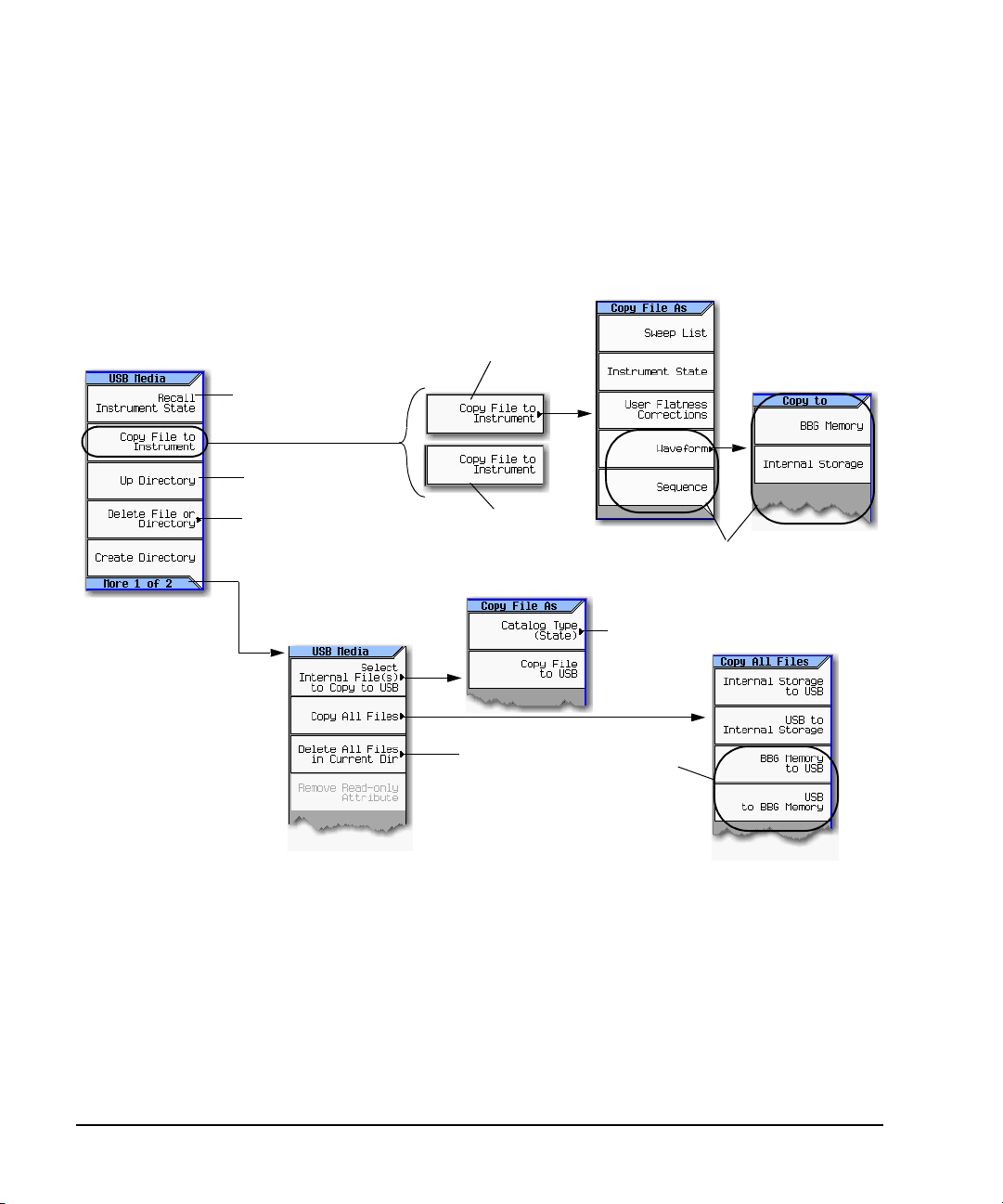
Basic Operation Preliminary
Selecting a waveform or
an unknown file type
displays this softkey.
File > Catalog Type > <type> > More > USB File Manager
or
File > More > USB File Manager
or
Insert the USB Flash Drive (UFD)
For details on each key, use key help as described on page42.
This key changes,
depending on the selected
file. See page 67
Whether a menu is available
depends on the selected file.
Requires confirmation
Catalog Type Menu
page 63
Requires confirmation
Moves up one directory level
These softkeys only are
available on the
N5162A1/82A with
BBG.
These softkeys
are only
available on
the N5182A
with BBG.
1
The N5162A is identical to an MXG
with a front panel display, except that the front panel, hardkeys and softkeys functionality are only
available through SCPI commands or the Web–Enabled MXG. For information on the Web-Enabled
MXG, refer to the Installation Guide, the Programming Guide and the SCPI Command Reference.
If the file type is recogni zed
the “Filename.xxx copied
to Internal Storage” is
displayed.
Working with Files Preliminary
Moving a File from One Media to Another
Use the USB Media Manager to move files between USB and internal media.
68 Agilent N5161A/62A/81A/82A/83A MXG Signal Generators User’s Guide
Page 83

Working with Instrument State Files
When saved to the signal generator, instrument settings
(states) save to instrument state memory*. Instrument
state memory is divided into 10 sequences (0 through 9);
each sequence comprises 100 registers (00 through 99).
Delete softkeys in the Save and Recall menus enable you
to delete the contents of a specific register, or the contents
of all sequences in the state file catalog.
The signal generator requires that you confirm a deletion.
*
Caution
T
o avoid the loss of data, GPIB settings, or current user
instrument states that have not been permanently saved
to non-volatile memory, the MXG should always be
powered down either via the MXG's front panel power
button or the appropriate SCPI command. MXG's
installed in rack systems and powered down with the
system rack power switch rather than the MXG's front
panel switch display a Error -310 due to the MXG not
being powered down correctly.
For details on each key, use key help
as described on page 42.
• Saving an Instrument State on page 70
• Saving a User Preset on page 70
• Recalling an Instrument State on page 70
• Recalling an Instrument State and Associated Waveform File on page 71
• Recalling an Instrument State and Associated List File on page 71
• Moving or Copying a Stored Instrument State on page 72
Figure 3-10 Save and Recall Softkeys
Preliminary Basic Operation
Preliminary Working with Files
The following information is not stored in a state file:
System Security Level List Mode Freq Hostname Remot e Language FM Deviation
System Security Level Display List Mode Power IP Address FTP Server PM Deviation
System Security Level State List Mode Dwell Subnet Mask Manual DHCP MAC
Web Server (HTTP) List Mode Sequence Default Gateway VXI–11 SCPI User Power Correction
Sockets SCPI (TELNET) Display Stat e On/Off ARB Files List Files I/Q Calibration Data
Agilent N5161A/62A/81A/82A/83A MXG Signal Generators User’s Guide 69
Page 84

Basic Operation Preliminary
Working with Files Preliminary
Saving an Instrument State
1. Preset the signal generator and set the following:
• Frequency: 800 MHz • Amplitude: 0 dBm • RF: on
2. (Optional, vector models only) Associate a waveform file with these settings:
a. Press Mode > Dual ARB > Select Waveform.
b. Highlight the desired file and press Select Waveform. If the file is not listed, you must first
move it from internal or external media to BBG media, see page 134.
3. Select the desired memory sequence (for this example, 1): Press Save > Select Seq > 1 > Enter.
4. Select the desired register (in this example, 01): Press Select Reg > 1 > Save Reg.
If a waveform is currently selected, saving the instrument state also saves a pointer to the
waveform file name.
5. Add a descriptive comment to sequence 1 register 01:
Press Add Comment to Seq[1] Reg[01], enter the comment and press Enter. The comment appears in
the Saved States list when you press Recall. If the instrument state has an associated waveform,
entering the waveform name in the comment makes it easy to identify which instrument state
applies to which waveform.
Saving a User Preset
A user preset is a special type of instrument state file.
1. Preset the signal generator and set as desired.
2. Press User Preset > Save User Preset.
This saves a state file named USER_PRESET, which the signal generator recognizes as containing
user preset information.
You can set up several preset conditions under different names:
1. After you save a user preset, rename it to something other than USER_PRESET (see page 72).
2. Save as many user presets as you wish, renaming the USER_PRESET file each time.
3. Give the desired file the name USER_PRESET.
Recalling an Instrument State
1. Preset the signal generator.
2. Press Recall.
The Select Seq softkey shows the last sequence used, and the display lists any states stored in the
registers in that sequence; RECALL Reg is the active entry.
3. Select the desired instrument state:
If the desired state is listed in the currently selected sequence, press desired number > Enter.
If not, press Press Select Seq > desired number > Enter > RECALL Reg > desired number > Enter.
70 Agilent N5161A/62A/81A/82A/83A MXG Signal Generators User’s Guide
Page 85

Preliminary Basic Operation
Preliminary Working with Files
Recalling an Instrument State and Associated Waveform File
1. Ensure that the desired waveform file exists, and that it is in BBG media (page 134).
If the waveform file is not in BBG media, this procedure generates an error.
Recalling an instrument state with an associated waveform file recalls only the waveform name. It
does not recreate the waveform file if it was deleted, or load the file into BBG media if it is in
internal or USB media.
2. Recall the desired instrument state (see previous example).
3. View the waveform file name recalled with the instrument state: press Mode > Dual ARB.
The name is displayed as the selected waveform.
4. Turn on the waveform file: Press Mode > Dual ARB > ARB Off On.
Recalling an Instrument State and Associated List File
Recalling an instrument state recalls only the list sweep setup. It does not recall the frequency
and/or amplitude values. Because you must load the list file from the file catalog, when you store a
list file, be sure to give it a descriptive name (up to 25 characters).
1. Recall the desired instrument state (see previous example).
2. Load the desired list file:
a. Press Sweep > More > Configure List Sweep > More > Load/Store.
b. Highlight the desired file and press Load From Selected File > Confirm Load From File.
Editing The Comment on an Instrument Comment
Use the following steps to change a comment on an instrument state saved using the Save key. This
is not the file name that appears in the State catalog (which is the file’s memory location).
1. Press Save
2. Highlight the desired register
3. Press Edit Comment In Seq[n] Reg [nn].
4. Press Re–SAVE Seq[n] Reg[nn].
This overwrites previously saved instrument state settings with the new comment.
Agilent N5161A/62A/81A/82A/83A MXG Signal Generators User’s Guide 71
Page 86

Basic Operation Preliminary
Sequence Register
The signal generator recognizes only the file named USER_PRESET as user preset information (page 70).
Working with Files Preliminary
Moving or Copying a Stored Instrument State
Figure 3-11 Instrument State File Catalog
A user–created state file’s default name is its memory location (sequence and register).
To move the file, rename it to the desired sequence and register; you can not give a file the same
name as an existing file. If you rename a state file to something other than a valid sequence/register
name, the file does not appear in either the Save or Recall menu.
72 Agilent N5161A/62A/81A/82A/83A MXG Signal Generators User’s Guide
Page 87

Preliminary Basic Operation
File > More >
Current
selection
Memory in the instrument is used, and USB media is ignored.
Media attached to the front panel USB connector is used, and no user
data is stored to internal storage.
This is the recommended selection. When USB media is attached to the
front panel, it is the selected media; when USB media is not attached,
internal storage is used.
For details on each key, use key help as described on page 42.
Select the directory on the USB media to be used for all file operations
when USB media is attached and enabled.
Preliminary Working with Files
Selecting the Default Storage Media
You can configure the signal generator to store user files to either the internal storage or to external
USB media. To automatically switch between USB media and internal storage, depending on whether
USB media is attached, select Automatically Use USB Media If Present. To avoid storing any confidential
information in the instrument, select Use Only USB Media. To avoid storing any confidential information
to USB media, select Use Only Internal Storage.
This selection is unaffected by power−cycle or preset.
Agilent N5161A/62A/81A/82A/83A MXG Signal Generators User’s Guide 73
Page 88

Basic Operation Preliminary
Error Number
Error Message
Error Description
(May be truncated on the
−222 Data out of range; value clipped to lower limit.
Indicates that the user has entered a deviation, depth, or internal
source frequency that is beyond the specific limits
Explanation is provided in the E rror Message file (see page 313)
(This is not displayed on the instrument)
Message number and longer description
new indicates a message generated
since messages were last viewed.
The annunciator indicates an unviewed message.
Error messages appear in the lower left corner
of the display as they occur.
Reading Error Messages Preliminary
Reading Error Messages
If an error condition occurs, the signal generator reports it to both the front panel display error
queue and the SCPI (remote interface) error queue. These two queues are viewed and managed
separately; for information on the SCPI error queue, refer to the Programming Guide.
Characteristic Front Panel Display Error Queue
Capacity (#errors) 30
Overflow Handling Drops the oldest error as each new error comes in.
Viewing Entries Press: Error > View Next (or Previous) Error Page
Clearing the Queue Press: Error > Clear Error Queue(s)
a
Unresolved Erro rs
No Er rors
a
Errors that must be resolved. For example, unlock.
Error Message Format
In the front panel display error
queue, error messages display on
an enumerated ("1 of N") basis.
Re–reported after queue is cleared.
When the queue is empty (every error in the queue has been read, or the queue is cleared), the
following message appears in the queue:
No Error Message(s) in Queue 0 of 0
74 Agilent N5161A/62A/81A/82A/83A MXG Signal Generators User’s Guide
Page 89

4 Using Analog Modulation (Option UNT Only)
page 77
page 77
page 77
For details on each key, use key help
as described on see page42.
NOTE The Mod On/Off hardkey and LED functionality are only valid for MXGs with Option UNT
installed.
Before using this information, you should be familiar with the basic operation of the signal generator.
If you are not comfortable with functions such as setting the power level and frequency, refer to
Chapter 3, “Basic Operation,” on page 41 and familiarize yourself with the information in that
chapter.
• The Basic Procedure on page 76
• Using an External Modulation Source on page 77
• Removing a DC Offset on page 77
Figure 4-1 Analog Modulation Softkeys
Agilent N5161A/62A/81A/82A/83A MXG Signal Generators User’s Guide 75
Page 90

Using Analog Modulation (Option UNT Only)
The Basic Procedure
The Basic Procedure
1. Preset the signal generator.
2. Set the carrier (RF) frequency.
3. Set the RF amplitude.
4. Configure the modulation:
AM FM ΦM
a. Press AM
b. Set the AM type (Linear or Exponential):
AM Type to highlight desired type.
c. Set the AM Mode (Normal or Deep).
Default is Deep. To select Normal enable
More to highlight desired type.
d. Set the AM Depth:
Default 0.01%
Range 0.01 to 100%
e. Set the rate:
AM Rate > value > frequency unit
AM Depth > value
a. Press FM/ΦM
b. Set the deviation:
FM Dev > value > frequency unit
c. Set the rate:
FM Rate > value > frequency unit
a. Press FM/ΦM > FM ΦM
b. Set the BW (normal or high):
FM ΦM to highlight desired type
c. Set the deviation:
ΦMDev > value > pi rad
d. Set the rate:
ΦM Rate > value > frequency unit
5. Turn on the modulation:
AM FM ΦM
AM Off On softkey to On FM Off On softkey to On ΦM Off On softkey to On
The appropriate modulation annunciator displays, indicating that you enabled modulation.
6. Turn on the RF output.
The RF output LED lights, indicating that the signal is transmitting from the RF output connector.
If the modulation does not seem to be working properly, refer to “No Modulation at the RF Output”
on page 308.
See also “Modulating the Carrier Signal” on page 60.
76 Agilent N5161A/62A/81A/82A/83A MXG Signal Generators User’s Guide
Page 91

Using an External Modulation Source
AM input
Rear panel inputs are
described on page 15
FM or ΦM input
Default
Select to use external modulation
Currently selected modulation.
Using Analog Modulation (Option UNT Only)
Using an External Modulation Source
Removing a DC Offset
To eliminate an offset in an externally applied FM or ΦM signal, perform a DCFM or DCΦM
Calibration.
NOTE You can perform this calibration for internally generated signals, but DC offset is not usually
1. Set up and turn on the desired modulation.
2. Press FM/ΦM > More > DCFM/DCΦM Cal.
Performing the calibration with a DC signal applied removes any deviation caused by the DC signal,
and the applied DC level becomes the new zero reference point. When you disconnect the DC signal,
perform the calibration again to reset the carrier to the correct zero reference.
Agilent N5161A/62A/81A/82A/83A MXG Signal Generators User’s Guide 77
a characteristic of an internally generated signal.
Page 92

Using Analog Modulation (Option UNT Only)
Using an External Modulation Source
78 Agilent N5161A/62A/81A/82A/83A MXG Signal Generators User’s Guide
Page 93

5 Optimizing Performance
NOTE For the N5161A/62A the softkey menus and features mentioned in this guide are only
Before using this information, you should be familiar with the basic operation of the signal generator.
If you are not comfortable with functions such as setting the power level and frequency, refer to
Chapter 3, “Basic Operation,” on page 41 and familiarize yourself with the information in that
chapter.
• Using the Dual Power Meter Display on page 80
• Using Flatness Correction on page 88
• Using External Leveling (N5183A Only) on page 97
• Using Unleveled Operating Modes on page 105
• Using an Output Offset, Reference, or Multiplier on page 107
• Using Free Run, Step Dwell, and Timer Trigger on page 111
• Using LXI on page 113
• Using a USB Keyboard on page 119
available through the Web–Enabled MXG or through SCPI commands. For information on the
Web-Enabled MXG, refer to the Installation Guide, the Programming Guide, and to the SCPI
Command Reference.
Agilent N5161A/62A/81A/82A/83A MXG Signal Generators User’s Guide 79
Page 94

Optimizing Performance Preliminary
Once turned on, the
power meter
readings are always
visible, even if
another instrument
feature is selected
(i.e. Sweep, AM,
etc.).
This area is the main
display for the dual
power meter
calibration frequency
and current power
measured.
If channel A or
channel B power
sensors or both are
displayed, and the
AMPTD or the FREQ
softkeys are pressed,
the large power
meter measurements
remains displayed.
After the first
connection, if the
connection is
successful, the
model number and
serial number of the
power sensor is
displayed.
For details on each key, use key help as described on see page 42.
Using the Dual Power Meter Display Preliminary
Using the Dual Power Meter Display
The dual power meter display can be used to display the current frequency and power of either one
or two power sensors. The display outputs the current frequency and power measured by the power
sensors in the larger center display and in the upper right corner of the display. Refer to Figure 5- 2,
Figure 5- 2, and Figure 5-3.
NOTE The dual power meter display feature is only available on instruments with serial prefixes
US/MY/SG4818.
>
To use two U2000 USB Series power sensors with the MXG, a USB hub (with power supply),
can be connected to the MXG’s front panel USB connector.
Figure 5-1 Dual Power Meter Display with Power Sensors A and B Calibrated
80 Agilent N5161A/62A/81A/82A/83A MXG Signal Generators User’s Guide
Page 95

Figure 5-2 Dual Power Meter Display Menu
See
page 82
Enables the power sensor on
channel A.
Enables the power sensor on
channel B.
Channel B is configured similarly to
channel A. See page 82
For details on each key, use key help
as described on see page 42.
Preliminary Using the Dual Power Meter Display
Preliminary Optimizing Performance
Agilent N5161A/62A/81A/82A/83A MXG Signal Generators User’s Guide 81
Page 96

Optimizing Performance Preliminary
AUX Fctn > Power Meter
Measurements
Sockets LAN: Sets the
IP port to 5025 (sta ndard)
or 5023 (telnet)
programming.
Sets the power meter’s IP
address or LAN–GPIB
gateway’s IP address (Sockets
LAN and VXI–11 LAN only).
Whether a softkey is available
depends on the selected
Connection Type.
VXI–11 LAN: Opens a
menu for entering a
device name for the
power meter being used.
Enables the power meter
connection type: Sockets
LAN, VXI–11 LAN, or USB.
Note: The VXI–11 softkey is
used to communicate
remotely with a pow er mete r
that has a GPIB connector
via LAN–GPIB gateway.
USB U2000A Series Power
Sensors do not require the
sensor to be calibrated.
The MXG uses the USB
U2000A Series Power
Sensor’s “Internal” zero.
Refer to the USB U2000A
Series Power Sensor’s
documentation.
Zero Sensor and
Calibrate Sensor softkeys
are inactive during a
measurement.
Selects the frequency that
channel A has been calibrated to.
Selects the channel on the
external power meter that the
power sensor is connected to.
Enables a power offset in dB for
the current channel.
Enables averaging. Instrument
default is Auto with 1024 points.
Note: This figure illustrates channel A, but channel B is similar.
For details on each key , use key help as
described on see page 42.
Using the Dual Power Meter Display Preliminary
Figure 5-3 Configuring the Power Sensor Channels
82 Agilent N5161A/62A/81A/82A/83A MXG Signal Generators User’s Guide
Page 97

Preliminary Using the Dual Power Meter Display
Preliminary Optimizing Performance
Example: Dual Power Meter Calibration
In the following example a U2004A USB Power Sensor is connected to channel A and a N1912A
P–Series Power Meter and 8482A Power Sensor are connected to channel B and are zeroed and
calibrated, as required.
On the MXG:
1. Setup MXG for Step Sweep. “Configuring a Swept Output” on page 48.
CAUTION Verify RF Output power is off before continuing.
2. Connecting the Channel A power sensor: Connect USB sensor to MXG. The MXG should display a
message across the bottom that reads similar to:
USB TMC488 device (USB POWER SENSOR,MY47400143) connected
Figure 5-4 MXG Displays Connection to U2000 USB Power Sensor
3. Press Aux Fctn > Power Meter Measurements > Channel A Setup > Connection Settings > Connection Type >
USB Device (None) > USB POWER SENSOR (MY47400143)
4. Press Return > Zero Sensor
A diagnostic dialog box appears the initial time that a U2000 Series power sensor with a
different serial number is connected to the MXG (refer to Figure 5-5). After the U2000 has been
recognized by the MXG, the U2000 power sensor is saved as a softkey in the instrument and the
dialog box in Figure 5- 5 won’t be displayed (press DONE, if you see this message).
Figure 5-5 Diagnostic Dialog Box for USB Sensor
A Running Calibration(s) bar is displayed on the MXG. Refer to Figure 5- 6 on page 84.
Agilent N5161A/62A/81A/82A/83A MXG Signal Generators User’s Guide 83
Page 98

Optimizing Performance Preliminary
For details on
each key, use key
help as described
on see page 42.
For details on
each key, use key
help as described
on see page 42.
Using the Dual Power Meter Display Preliminary
Figure 5-6 Running Calibration(s) Bar (Zeroing Sensor)
NOTE The U2000 Series USB Power Sensor, does not require a 50 MHz calibration. If a
calibration is attempted with the U2000 Series Power Sensors, the MXG displays a
message reading:
The U2000 series power sensor does not require a 50 MHz calibration. Refer to
Figure 5- 7 on page 84.
Figure 5-7 Diagnostic Dialog Box Displayed for U2000 Power Sensor
5. Press Return > Return > Channel A to On
The current power meter sensor reading should be displayed in the ChA portion of the
instrument's display and in the upper right portion of the display under Power Meter. Refer to
Figure 5- 8.
84 Agilent N5161A/62A/81A/82A/83A MXG Signal Generators User’s Guide
Page 99

Preliminary Using the Dual Power Meter Display
For details on
each key, use key
help as described
on see page 42.
For details on
each key, use key
help as described
on see page 42.
Preliminary Optimizing Performance
Figure 5-8 Channel A Power Sensor Displayed on MXG
6. On the N1912A P–Series Power Meter (Channel B power sensor): Connect the N1912A P–Series
Power Meter to the LAN.
7. Connect the power meter sensor to channel B of the power meter.
NOTE It is recommended, but not required to use the channel B on the N1912A. This provides
continuity with the MXG’s dual display. For this example, the U2004A has already used
up the channel A position on the MXG.
8. Connect the power sensor input to the 50 MHz reference of the power meter.
9. Press Channel B Setup
10. Press Connection Settings > Sockets
11. Press IP Address > IP address > Enter
NOTE The IP address of the power meter should be displayed in the ChB section of the display.
Figure 5-9 Channel B Power Sensor with IP Address Entered
12. Press Return > Channel Settings > External Power Meter Channel to B
Agilent N5161A/62A/81A/82A/83A MXG Signal Generators User’s Guide 85
Page 100

Optimizing Performance Preliminary
For details on
each key, use key
help as described
on see page 42.
For details on
each key, use key
help as described
on see page 42.
Using the Dual Power Meter Display Preliminary
13. On the MXG: Press Channel B to On and then back to Off again. This initializes the MXG to the
external power meter.
14. Press Return > Zero Sensor
A diagnostic dialog box is displayed each time an external power meter is being used and the
Zero Sensor or Calibrate Sensor softkey is pressed (refer to Figure 5- 10 on page 86).
Verify the power sensor is connected to the 50 MHz reference of the power meter.
Figure 5-10 Diagnostic Dialog Box for Channel B
15. Press Done
The Running Calibration(s) bar is displayed: Zeroing Sensor Please wait....
16. After Running Calibration(s) bar disappears: Press Calibrate Sensor
Diagnostic Dialog box is displayed that prompts for verifying the connection of the power sensor
to the power meter 50 MHz reference (refer to Figure 5- 11 on page 86).
Figure 5-11 Diagnostic Dialog Box for Calibration
86 Agilent N5161A/62A/81A/82A/83A MXG Signal Generators User’s Guide
 Loading...