

Page 1

Agilent 7200
Accurate-Mass/Q-TOF
GC/MS System
Troubleshooting and
Maintenance Manual
Agilent Technologies
Page 2

Notices
CAUTION
WARNING
© Agilent Technologies, Inc. 2012, 2014
No p art o f this manu al may be re produce d in
any form or by any means (including electronic storage and retrieval or translation
into a foreign language) without prior agreement and written consent from Agilent
Technologies, Inc. as governed by United
States and international copyright laws.
Manual Part Number
G3850-90009
Edition
First Edition, August 2014
Printed in USA
Agilent Technologies, Inc.
5301 Stevens Creek Boulevard
Santa Clara, CA 95051
Warranty
The material contained in this document is provided “as is,” and is subject to being changed, without notice,
in future editions. Further, to the maximum extent permitted by applicable
law, Agilent disclaims all warranties,
either express or implied, with regard
to this manual and any information
contained herein, including but not
limited to the implied warranties of
merchantability and fitness for a particular purpose. Agilent shall not be
liable for errors or for incidental or
consequential damages in connection with the furnishing, use, or performance of this document or of any
information contained herein. Should
Agilent and the user have a separate
written agreement with warranty
terms covering the material in this
document that conflict with these
terms, the warranty terms in the separate agreement shall control.
Safety Notices
A CAUTION notice denotes a
hazard. It calls attention to an
operating procedure, practice, or
the like that, if not correctly
performed or adhered to, could
result in damage to the product or
loss of important data. Do not
proceed beyond a CAUTION notice
until the indicated conditions are
fully understood and met.
A WARNING notice denotes a
hazard. It calls attention to an
operating procedure, practice, or
the like that, if not correctly
performed or adhered to, could
result in personal injury or death.
Do not proceed beyond a
WARNING notice until the
indicated conditions are fully
understood and met.
2 Troubleshooting and Maintenance Manual
Page 3

Contents
1 Introduction
Abbreviations Used 8
The 7200 Accurate-Mass Quadrupole Time-of-Flight GC/MS
System 10
7200 Accurate-Mass Q-TOF GC/MS Description 12
Side Panel AC Power Connectors 13
Back Panel Connectors 14
Interfacing Start Events to External Devices 15
Remote control processor 15
Remote start signals 15
System ready 15
Start run input 16
Important Safety Warnings 17
Safety and Regulatory Certifications 20
Intended Use 23
Cleaning/Recycling the Product 23
Moving or Storing the MS 23
2 General Troubleshooting
Troubleshooting Tips and Tricks 26
General Symptoms 27
Chromatographic Symptoms 29
Mass Spectra General Symptoms 34
Pressure Symptoms 36
Temperature Symptoms 38
Troubleshooting and Maintenance Manual 3
Page 4

Common Types of Errors 40
Air Leaks 45
Contamination 46
3 CI Troubleshooting
Common CI-Specific Problems 50
Troubleshooting Tips and Tricks 51
Air Leaks 52
Pressure-Related Symptoms 55
Signal-Related Symptoms 58
Tuning-Related Symptoms 64
The CI ion source is dirty 65
Air leak 65
4 General Maintenance
Before Starting 68
Scheduled maintenance 68
Tools, spare parts, and supplies 69
High voltage precautions 69
Dangerous temperatures 69
Chemical residue 70
Electrostatic discharge 71
To Refill the EI Calibration Vial 72
Materials needed 72
Refill 72
To Refill the IRM Vial 74
Materials needed 74
Procedure 74
To Connect the GC Nitrogen Gas Source to the Collision Cell 76
4 Troubleshooting and Maintenance Manual
Page 5

5 CI Maintenance
Materials needed 76
Procedure 76
To Replace the Seals in the RIS Probe 77
Materials needed 77
Procedure 77
To Separate the GC from the MS 79
Materials needed 79
Procedure 79
To Position the GC Next to the MS 82
Procedure 82
To Move or Store the MS 83
Materials needed 83
Procedure 83
To Access the Left Side Lifting Handle 86
Materials needed 86
Procedure 87
To Minimize Foreline Pump Damage from Ammonia 90
To Replace the Methane/Isobutane Gas Purifier 91
To Clean the Reagent Gas Supply Lines 92
To Refill the CI Calibration Vial 93
Materials needed 93
Refill 93
6Vacuum System
Overview 96
Maintaining the Vacuum System 97
Periodic maintenance 97
Other procedures 97
Troubleshooting and Maintenance Manual 5
Page 6

Vacuum System Components 97
Common Vacuum System Problems 98
Foreline Pump 99
To check the oil mist filter 99
To check the foreline pump fluid level 100
To add foreline pump fluid 100
To replace the foreline pump fluid 101
Side Plate 104
Vacuum Seals 104
Calibration Valves 105
EI Calibration Valve 105
CI Calibration Valve 106
IRM Calibration Valves 107
7Replacement Parts
To Order Parts 110
Electronics 111
Vacuum System 116
Analyzer 121
RIS Manifold 130
GC/MS Interface 132
Consumables and Maintenance Supplies 133
6 Troubleshooting and Maintenance Manual
Page 7

Agilent 7200 Accurate-Mass Q-TOF GC/MS System
Troubleshooting and Maintenance Manual
1
Introduction
Abbreviations Used 8
The 7200 Accurate-Mass Quadrupole Time-of-Flight GC/MS System 10
7200 Accurate-Mass Q-TOF GC/MS Description 12
Side Panel AC Power Connectors 13
Interfacing Start Events to External Devices 15
Important Safety Warnings 17
Safety and Regulatory Certifications 20
Intended Use 23
Cleaning/Recycling the Product 23
Moving or Storing the MS 23
This section provides general information about the 7200 Accurate-Mass
Quadrupole Time-of-Flight (Q-TOF) GC/MS System, including a hardware
description and general safety warnings.
Agilent Technologies
7
Page 8

1 Introduction
Abbreviations Used
The abbreviations in Table 1 are used in discussing this product. They are
collected here for convenience.
Tab l e 1 Abbreviations
Abbreviation Definition
AC Alternating current
ALS Automatic liquid sampler
BFB Bromofluorobenzene (calibrant)
CC Collision cell
CI Chemical ionization
DC Direct current
DFTPP Decafluorotriphenylphosphine (calibrant)
DIP Direct insertion probe
EI Electron impact
EPC Electronic pneumatic control
eV Electron volt
GC Gas chromatograph
id Inside diameter
IRM Internal Reference Mass
LAN Local Area Network
m/z Mass to charge ratio
MFC Mass flow controller
MS Mass spectrometer
MS1 Front quadrupole
NCI Negative chemical ionization
OFN Octafluoronaphthalene (sample)
8 Troubleshooting and Maintenance Manual
Page 9

Tab l e 1 Abbreviations (continued)
Abbreviation Definition
PCI Positive chemical ionization
PFDTD Perfluoro-5,8-dimethyl-3,6,9-trioxydodecane (calibrant)
PFET 2,4,6-tris (Pentafluoroethyl)-1,3,5-triazine
PFTBA Perfluorotributylamine (calibrant)
Q-TOF Quadrupole time-of-flight
Quad Quadrupole mass filter
RF Radio frequency
RFPA Radio frequency power amplifier
TOF Time-of-flight
Torr Unit of pressure, 1 mm Hg
Turbo Turbomolecular vacuum pump
Introduction 1
Troubleshooting and Maintenance Manual 9
Page 10

1 Introduction
The 7200 Accurate-Mass Quadrupole Time-of-Flight GC/MS System
The 7200 Accurate-Mass Quadrupole Time-of-Flight (Q-TOF) GC/MS System is
a standalone capillary GC detector for use with the Agilent 7890 Series gas
chromatograph. The 7200 Q-TOF features:
• Three turbomolecular vacuum pumps
• Rotary vane foreline pump
• Independently MS-heated EI or CI ion source
• Removable ion source (RIS) probe with bayonet and cooling chamber, which
allows quick change from EI to CI source with minimal loss of vacuum in
the instrument
• Independently MS-heated hyperbolic quadrupole mass filter, which can be
heated to high temperatures, minimizing the contamination typical with
low temperature analyses
• Single hexapole collision cell
• Vacuum-insulated f light tube with dual-stage ion mirror
• Fast electronics, allowing fast sampling rates
• Analog to digital detector
• Independently GC-heated GC/MS interface with automatic retraction
during source removal
Physical description
The 7200 Q-TOF GC/MS is approximately 48 cm high, 71 cm wide, and 89 cm
deep. The flight tube extends 84 cm up over the top of the instrument. The RIS
probe handle, when attached, extends 48 cm from the front of the instrument.
The weight of the instrument is 152 kg for the turbo pump mainframe. The
attached foreline (roughing) pump weighs an additional 22.2 kg.
The basic components of the instrument are: the frame/cover assemblies, the
vacuum system, the GC/MS interface, the removable ion source, the f light tube
electronics, the collision cell, the detector, and the analyzer.
10 Troubleshooting and Maintenance Manual
Page 11

Vacuum gauge
The 7200 Q-TOF GC/MS is equipped with four ion vacuum gauges:
• RIS vacuum chamber
• Vacuum manifold chamber
• TOF vacuum manifold chamber
• Turbomolecular vacuum pumps exhaust
The MassHunter Workstation can be used to read the pressure (high vacuum)
in the vacuum manifold, at the turbomolecular vacuum pump discharge, and
the flight tube.
Ionization modes
The G3851BA 7200 Accurate-Mass Q-TOF GC/MS comes standard with both an
EI and CI removable ion source (RIS).
A methane/isobutane gas purifier is provided and is required. It removes
oxygen, water, hydrocarbons, and sulfur compounds.
The MS CI system has been optimized to achieve the relatively high source
pressure required for CI while still maintaining high vacuum in the collision
cell, quadrupole, and TOF tube. Special seals along the flow path of the
reagent gas and very small openings in the ion source keep the source gases in
the ionization volume long enough for the appropriate reactions to occur.
Introduction 1
The interface has special plumbing for reagent gas. A retractable insulating
seal fits onto the tip of the interface and is used for both EI and CI.
Switching back and forth between CI and EI sources takes less than 30
minutes with the new removable ion source. The RIS allows the instrument to
remain close to pressure, and provides a cooling chamber with N2 purge for
rapid source cooling without venting the machine. This saves hours in cycle
time over the traditional unit.
Troubleshooting and Maintenance Manual 11
Page 12
1 Introduction
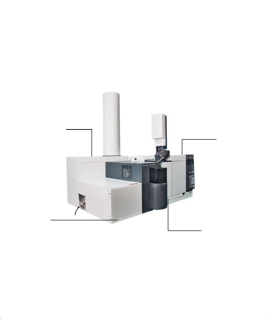
7200 Series MS
MS power
switch
7890 GC
GC power switch
7200 Accurate-Mass Q-TOF GC/MS Description
Figure 1 is an overview of a typical 7200 Accurate-Mass Q-TOF GC/MS system.
Figure 1 7200 Q-TOF GC/MS System
12 Troubleshooting and Maintenance Manual
Page 13
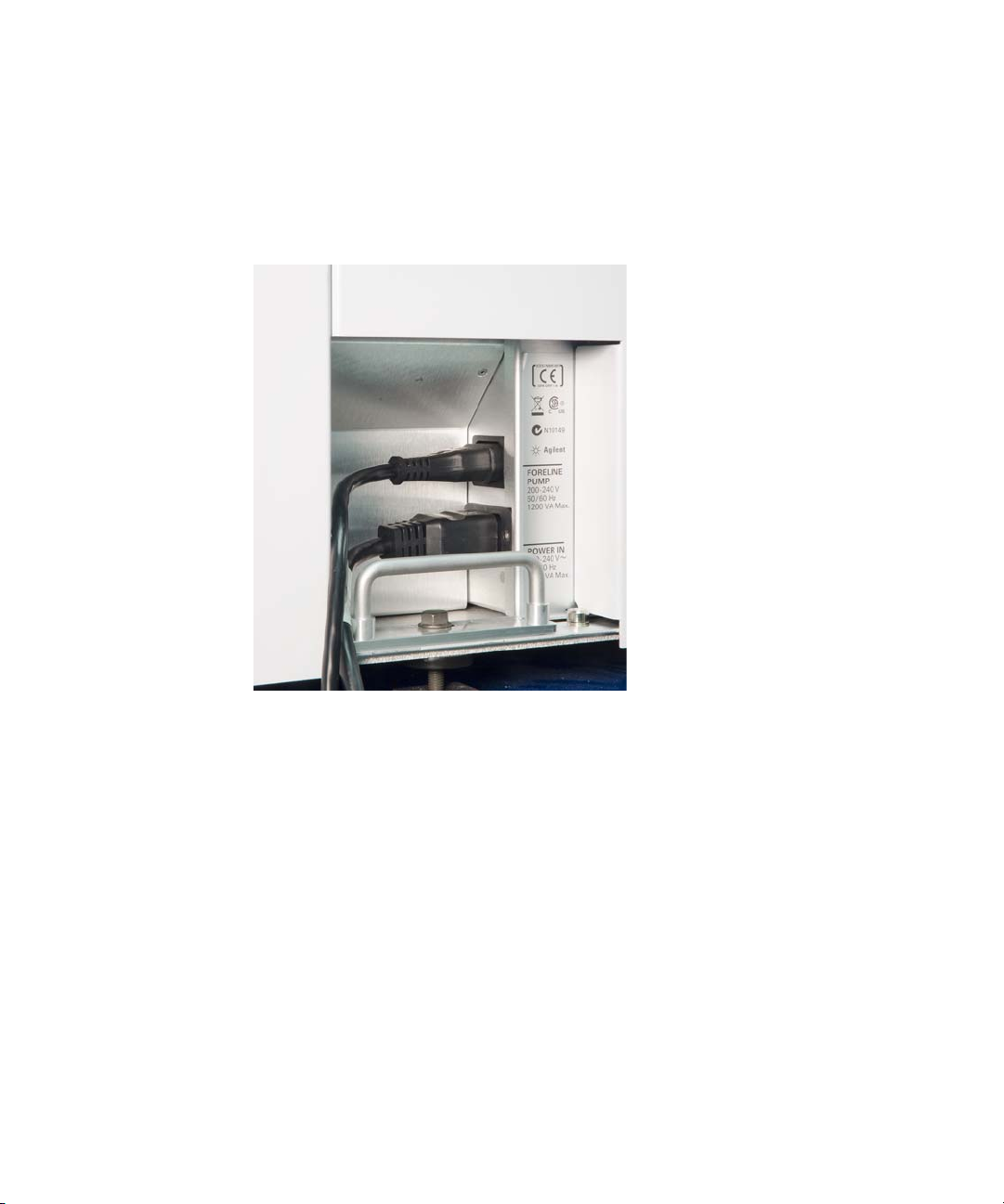
Side Panel AC Power Connectors
Introduction 1
Figure 2 Side panel power supply (left) and back panel connections (right)
Foreline pump power receptacle (top)
The foreline pump power cord receptacle located on the left side of the MS
provides AC power for the foreline pump. If the power switch is off, no power
is supplied to the foreline pump.
Main power cord receptacle (bottom)
The AC power cord located on the left side of the MS brings in all electrical
power for the MS. The power cord can be detached from the MS.
Troubleshooting and Maintenance Manual 13
Page 14
1 Introduction
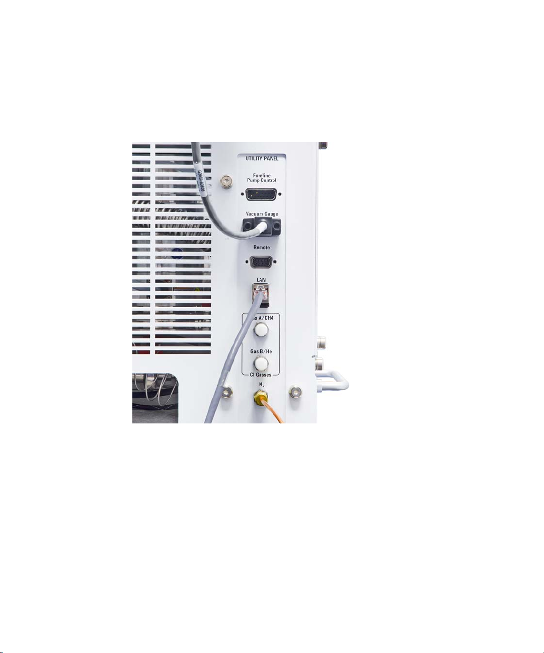
Back Panel Connectors
Figure 3 Side panel power supply (left) and back panel connections (right)
Remote start connector
The remote start connector is the external connector for the remote start
circuitry on the LAN/MS control card. It receives remote start signals from the
GC.
LAN (I/O) connector
The LAN cable from the data system is connected to the LAN communications
connector. It carries all data communication between the PC and the MS.
14 Troubleshooting and Maintenance Manual
Page 15

Interfacing Start Events to External Devices
Start Ground
Ready
Remote control processor
The remote control processor on the LAN/MS control card synchronizes
start-run signals with GCs and other devices. The functions of the remote
control processor are extended to the remote start (Remote) connector
(Figure 4) on the back panel of the MS. The remote start cable connects the GC
and the MS. An optional cable can extend these events to another instrument.
Remote start signals
It is often necessary to communicate with external devices (for example, a
purge-and-trap) during a run. Typically, these communications are requests to
send a system-ready signal. They also include:
• Receive a start run signal from an external device
• Program the timing of events during a run
Introduction 1
Figure 4 Remote start connector
System ready
When interfacing to an external device, it is often desirable to send a
system-ready signal to the device. In the case of a multi-sample Tekmar
purge-and-trap, each sample is purged onto a trap where it waits for a ready
signal. On receipt of the ready signal, the desorption cycle begins. When a
specific temperature is reached, the purge-and-trap closes a contact to
indicate the run has started.
Troubleshooting and Maintenance Manual 15
Page 16

1 Introduction
Start run input
The ready pin on the remote start connector on the GC is held low at all times
except when the GC, MS, and data system are all ready. On system ready, a
logic high of 5 VDC is present between that pin and any ground. This same
high can be detected between the ready and ground pins on the remote start
connector on the MS.
The best way to generate a start run signal is to use the remote start connector
on the GC. Since remote start cables are made for most common devices, this
is often the simplest way. A general-purpose remote start cable (Y-Remote
Start/Stop, NON APG p/n G1530-61200), is also available that terminates in
spade lugs. Care must be taken to ensure that the system is actually ready
before the start run signal is sent.
If necessary, the remote start connector on the back of the MS can be used to
send the start run signal. A contact closure between the start and ground pins
will start the run if the system is ready.
16 Troubleshooting and Maintenance Manual
Page 17

Important Safety Warnings
WARNING
WARNING
There are several important safety notices to always keep in mind when using
the MS.
Many internal parts of the MS carry dangerous voltages
If the MS is connected to a power source, even if the power switch is off,
potentially dangerous voltages exist on:
• The wiring between the MS power cord and the AC power supply
• The AC power supply itself
• The wiring from the AC power supply to the power switch
With the power switch on, potentially dangerous voltages also exist on:
• All electronics boards in the instrument
• The internal wires and cables connected to these boards
• The wires for any heater (oven, detector, inlet, or valve box)
Introduction 1
Troubleshooting and Maintenance Manual 17
All these parts are shielded by covers. With the covers in place, it should be difficult
to accidentally make contact with dangerous voltages. Unless specifically
instructed to, never remove a cover unless the detector, inlet, and oven are turned
off.
If the power cord insulation is frayed or worn, the cord must be replaced. Contact
your Agilent service representative.
Electrostatic discharge is a threat to MS electronics
The printed circuit boards in the MS can be damaged by electrostatic
discharge. Do not touch any of the boards unless it is absolutely necessary. If
you must handle them, wear a grounded wrist strap and take other antistatic
precautions.
Page 18

1 Introduction
WARNING
WARNING
WARNING
Precautions to take to prevent an explosion
The use of hydrogen gas is specifically prohibited with this product.
You MUST make sure the top thumbscrew on the front analyzer side plate and the
top thumbscrew on the rear analyzer side plate are both fastened finger-tight. Do not
overtighten the thumbscrews; this can cause air leaks.
You MUST leave the collision cell chamber top plate shipping brackets fastened. Do
not remove the shipping brackets from the top plate for normal operation; they
secure the top plate in the event of an explosion.
Failure to secure your MS as described above greatly increases the chance of
personal injury in the event of an explosion.
18 Troubleshooting and Maintenance Manual
Many parts are dangerously hot
Many parts of the GC/MS operate at temperatures high enough to cause
serious burns. These parts include, but are not limited to the:
• Inlet
• Oven and its contents
• Val ve box
• Column nuts attaching the column to an inlet or detector
• Foreline pump
• GC/MS transfer line
Always cool these areas of the system to room temperature before working on
them. They will cool faster if you first set the temperature of the heated zone
to room temperature. Turn the zone off after it has reached the setpoint. If you
must perform maintenance on hot parts, use a wrench and wear gloves.
Whenever possible, cool the part of the instrument that you will be
maintaining before you begin working on it.
Page 19

WARNING
Be careful when working behind the instrument. During cool-down cycles, the GC
WARNING
WARNING
emits hot exhaust that can cause burns.
The insulation around the inlets, detectors, valve box, and the insulation cups is
made of refractory ceramic fibers. To avoid inhaling fiber particles, we recommend
the following safety procedures: ventilate your work area; wear long sleeves,
gloves, safety glasses, and a disposable dust/mist respirator; dispose of insulation
in a sealed plastic bag in accordance with local regulations; wash your hands with
mild soap and cold water after handling the insulation.
The oil pan under the standard foreline pump can be a fire hazard
Oily rags, paper towels, and similar absorbents in the oil pan could ignite and
damage the pump and other parts of the MS.
Introduction 1
Combustible materials (or flammable/nonflammable wicking material) placed
under, over, or around the foreline (roughing) pump constitutes a fire hazard. Keep
the pan clean, but do not leave absorbent material such as paper towels in it.
Troubleshooting and Maintenance Manual 19
Page 20

1 Introduction
Safety and Regulatory Certifications
The 7200 Q-TOF GC/MS conforms to the following safety standards:
• Canadian Standards Association (CSA): CAN/CSA-C22.2 No. 61010-1-04
• CSA/Nationally Recognized Test Laboratory (NRTL): UL 61010–1
• International Electrotechnical Commission (IEC): 61010–1
• EuroNorm (EN): 61010–1
The 7200 Q-TOF GC/MS conforms to the following regulations on
Electromagnetic Compatibility (EMC) and Radio Frequency Interference
(RFI):
• CISPR 11/EN 55011: Group 1, Class A
• IEC/EN 61326-1
• AUS/NZ
This ISM device complies with Canadian ICES-001. Cet appareil ISM est
conforme a la norme NMB—001 du Canada.
The 7200 Q-TOF GC/MS is designed and manufactured under a quality system
registered to ISO 9001.
Information
The Agilent Technologies 7200 Accurate-Mass Q-TOF GC/MS meets the
following IEC (International Electrotechnical Commission) classifications:
Equipment Class I, Laboratory Equipment, Installation Category II, and
Pollution Degree 2.
This unit has been designed and tested in accordance with recognized safety
standards and is designed for use indoors. If the instrument is used in a
manner not specified by the manufacturer, the protection provided by the
instrument may be impaired. Whenever the safety protection of the MS has
been compromised, disconnect the unit from all power sources and secure the
unit against unintended operation.
20 Troubleshooting and Maintenance Manual
Page 21

Symbols
Introduction 1
Refer servicing to qualified service personnel. Substituting parts or
performing any unauthorized modification to the instrument may result in a
safety hazard.
Warnings in the manual or on the instrument must be observed during all
phases of operation, service, and repair of this instrument. Failure to comply
with these precautions violates safety standards of design and the intended
use of the instrument. Agilent Technologies assumes no liability for the
customer’s failure to comply with these requirements.
See accompanying instructions for more information.
Indicates a hot surface.
Indicates hazardous voltages.
Indicates earth (ground) terminal.
Indicates potential explosion hazard.
Indicates radioactivity hazard.
Indicates electrostatic discharge hazard.
Indicates that you must not discard this
electrical/electronic product in domestic household
waste.
Troubleshooting and Maintenance Manual 21
Page 22

1 Introduction
Electromagnetic compatibility
This device complies with the requirements of CISPR 11. Operation is subject
to the following two conditions:
• This device may not cause harmful interference.
• This device must accept any interference received, including interference
that may cause undesired operation.
If this equipment does cause harmful interference to radio or television
reception, which can be determined by turning the equipment off and on, the
user is encouraged to try one or more of the following measures:
1 Relocate the radio or antenna.
2 Move the device away from the radio or television.
3 Plug the device into a different electrical outlet, so that the device and the
radio or television are on separate electrical circuits.
4 Make sure that all peripheral devices are also certified.
5 Make sure that appropriate cables are used to connect the device to
peripheral equipment.
6 Consult your equipment dealer, Agilent Technologies, or an experienced
technician for assistance.
Changes or modifications not expressly approved by Agilent Technologies
could void the user’s authority to operate the equipment.
Sound emission declaration
Sound pressure
Sound pressure Lp < 70 dB according to EN 27779:1991 and
EN ISO 3744:1995.
Schalldruckpegel
Schalldruckpegel LP < 70 dB nach EN 27779:1991 und EN ISO 3744:1995.
22 Troubleshooting and Maintenance Manual
Page 23

Intended Use
Agilent products must only be used in the manner described in the Agilent
product user guides. Any other use may result in damage to the product or
personal injury. Agilent is not responsible for any damages caused, in whole or
in part, by improper use of the products, unauthorized alterations,
adjustments or modifications to the products, failure to comply with
procedures in Agilent product user guides, or use of the products in violation
of applicable laws, rules or regulations.
Cleaning/Recycling the Product
To clean the unit, disconnect the power and wipe down with a damp, lint-free
cloth. For recycling, contact your local Agilent sales office.
Moving or Storing the MS
Introduction 1
The best way to keep your MS functioning properly is to keep it pumped down
and hot, with carrier gas flow. If you plan to move or store your MS, a few
additional precautions are required. The MS must remain upright at all times;
this requires special caution when moving. The MS should not be left vented to
atmosphere for long periods. For more information, see “To Move or Store the
MS” on page 83.
Troubleshooting and Maintenance Manual 23
Page 24

1 Introduction
24 Troubleshooting and Maintenance Manual
Page 25

Agilent 7200 Accurate-Mass Q-TOF GC/MS System
Troubleshooting and Maintenance Manual
2
General Troubleshooting
Troubleshooting Tips and Tricks 26
General Symptoms 27
Chromatographic Symptoms 29
Mass Spectra General Symptoms 34
Pressure Symptoms 36
Temperature Symptoms 38
Common Types of Errors 40
Air Leaks 45
Contamination 46
This is a quick reference to symptoms and possible causes of the most
common problems experienced by users. For each symptom, one or more
possible causes are listed. In general, the causes listed first are the most likely
causes or the easiest to check and correct.
This chapter does not include corrective actions for the possible causes listed.
Some of the corrective actions required may be dangerous if performed
incorrectly. Do not attempt any corrective actions unless you are sure you
know the correct procedure and the dangers involved. See the other chapters
in this manual for more information.
If the material in this chapter and in the online help proves insufficient to help
you diagnose a problem, contact your Agilent Technologies service
representative.
Agilent Technologies
25
Page 26

2 General Troubleshooting
Troubleshooting Tips and Tricks
Rule 1: “Look for what has been changed.”
Many problems are introduced accidentally by human actions. Every time any
system is disturbed, there is a chance of introducing a new problem.
• If the MS was just pumped down after maintenance, suspect air leaks or
incorrect assembly.
• If carrier gas or helium gas purifier was just changed, suspect leaks or
contaminated or incorrect gas.
• If the GC column was just replaced, suspect air leaks or a contaminated or
bleeding column.
Rule 2: “If complex isn’t working, go back to simple.”
A complex task is not only more difficult to perform but also more difficult to
troubleshoot. If you’re having trouble detecting your sample, verify that
autotune is successful.
Rule 3: “Divide and conquer.”
This technique is known as “half-split” troubleshooting. If you can isolate the
problem to only part of the system, it is much easier to locate.
To determine whether an air leak is in the GC or the MS, you can vent the MS,
remove the column, and install the blank interface ferrule. If the leak goes
away, it was in the GC.
26 Troubleshooting and Maintenance Manual
Page 27

General Symptoms
This section describes symptoms you might observe when first turning on the
GC/MS system. All of these symptoms would prevent operation of the system.
GC does not turn on
Nothing happens when the GC is switched on. The GC fans do not turn on and
the keypad display does not light.
• Disconnected GC power cord
• No voltage or incorrect voltage at the electrical outlet
• Failed fuse in the GC
• GC power supply is not working correctly
MS does not turn on
Nothing happens when the MS is switched on. The foreline pump does not
start. The cooling fan for the high-vacuum pump does not turn on.
• Disconnected MS power cord
• No voltage or incorrect voltage at the electrical outlet
• Failed primary fuses - Not user replaceable
• MS electronics are not working correctly
General Troubleshooting 2
Foreline pump is not operating
The MS is receiving power (the fan is operating) but the foreline pump is not
operating.
• A large air leak (usually the analyzer door open) has caused pumpdown
failure. You must power cycle the MS to recover from this state.
• Disconnected foreline pump power cord
• Malfunctioning foreline pump
• Check power switch on foreline pump
Troubleshooting and Maintenance Manual 27
Page 28

2 General Troubleshooting
MS turns on but then the foreline pump shuts off
The MS will shut down both the foreline pump and the turbo pumps if the
system fails to pump down correctly. This is usually because of a large air leak
or the side plate has not sealed correctly. This feature helps prevent the
foreline pump from sucking air through the system, which can damage the
analyzer and the turbo pumps.
You must power cycle the MS to recover from this state.
28 Troubleshooting and Maintenance Manual
Page 29

Chromatographic Symptoms
These are symptoms you may observe in the chromatograms generated by data
acquisition. In general, these symptoms do not prevent you from operating
your GC/MS system. They indicate, however, that the data you are acquiring
may not be the best data obtainable. These symptoms can be caused by
instrument malfunctions but are more likely caused by incorrect
chromatographic technique.
Two of the symptoms, Low sensitivity and Poor repeatability also apply to
mass spectral data.
No peaks
If an analysis shows no chromatographic peaks, only a flat baseline or minor
noise, run the automated tune program. If the MS passes tune, the problem is
most likely related to the GC. If the MS does not pass tune, the problem is most
likely in the MS.
Passes tune
General Troubleshooting 2
• Incorrect sample concentration
• No analytes present
• Syringe missing from the ALS or not installed correctly
• Injection accidentally made in split mode instead of splitless mode
• Empty or almost empty sample vial
• Dirty GC inlet
• Leaking GC inlet*
• Loose column nut at the GC inlet*
* This could cause a fault condition in the GC that would prevent the GC
from operating.
Does not pass tune
• Calibration vial is empty
• Excessive foreline or analyzer chamber pressure
• Very d i r t y i o n s o ur c e
Troubleshooting and Maintenance Manual 29
Page 30

2 General Troubleshooting
• Calibration valve is not working correctly
• Bad signal cable connection
• Filament has failed or is not connected correctly
• Bad ion source wiring connection
• Bad detector wiring connection
• Failed MS detector
Peaks are tailing
• Active sites in the sample path
• Injection is too large
• Incorrect GC inlet temperature
• Insufficient column flow
• GC/MS interface temperature is too low
• Ion source temperature is too low
Peaks are fronting
• Column film thickness mismatched with analyte concentration (column
overload)
• Initial oven temperature is too low
• Active sites in the sample path
• Injection is too large
• GC inlet pressure too high
• Insufficient column flow
Peaks have flat tops
• Insufficient solvent delay
• Incorrect scale on the display
• Injection is too large
30 Troubleshooting and Maintenance Manual
Page 31

Peaks have split tops
• Bad injection technique
• Injection is too large
Baseline is rising
• Column bleed
• Other contamination
Baseline is high
• Column bleed
• Other contamination
General Troubleshooting 2
Baseline is falling
A falling baseline indicates contamination is being swept away. Wait until the
baseline reaches an acceptable level. Common causes include:
• Residual air and water from a recent venting
• Column bleed
• Septum bleed
• Splitless injection time too long (inlet is not properly swept, resulting in
excess solvent on the column and slow solvent decay)
Troubleshooting and Maintenance Manual 31
Page 32

2 General Troubleshooting
Baseline wanders
• Insufficient carrier gas supply pressure*
• Malfunctioning flow or pressure regulator*
• Intermittent leak in the GC inlet*
* This could cause a fault condition in the GC that would prevent the GC
from operating.
Retention times for all peaks drift – shorter
• Column has been shortened
• Initial oven temperature was increased
• Column is getting old
Retention times for all peaks drift – longer
• Column flow has been reduced
• Initial oven temperature was decreased
• Active sites in the sample path
• Leaks in the GC inlet*
* This could cause a fault condition in the GC that would prevent the GC
from operating.
Poor sensitivity
• Incorrect tuning, or tune file that does not match the type of analysis
• Repeller voltage is too low
• Incorrect temperatures (oven, GC/MS interface, ion source, or mass filter)
• Incorrect sample concentration
• Leaking GC inlet*
• Dirty GC inlet
• Incorrect split ratio
• Purge-off time in splitless mode is too short
32 Troubleshooting and Maintenance Manual
Page 33

• Excessive pressure in the analyzer chamber
• Dirty ion source
• Air leaks between chambers
• Poor filament operation
• Detector is not working correctly
• Incorrect mass filter polarity
• Collision cell voltage
* This could cause a fault condition in the GC that would prevent the GC
from operating.
Poor repeatability
• Dirty syringe needle
• Dirty GC inlet
• Leaking GC inlet*
• Injection is too large
• Loose column connections
• Variations in pressure, column flow, and temperature
• Dirty ion source
• Loose connections in the analyzer
• Ground loops
General Troubleshooting 2
* This could cause a fault condition in the GC that would prevent the GC
from operating.
Troubleshooting and Maintenance Manual 33
Page 34

2 General Troubleshooting
Mass Spectra General Symptoms
This section describes symptoms you might observe in mass spectra. Some of
these symptoms will appear in the mass spectra of samples. Others you will
observe only in a tune report. Some of these symptoms have causes that can be
corrected by the operator. Others, however, require service by an Agilent
Technologies service representative.
Two of the chromatographic symptoms, Poor sensitivity and Poor
repeatability also apply to mass spectra.
No peaks
• Ion source cables not connected
• Bad connections to or from the detector
• Detector power supply output cable has failed
• Collision cell voltages
• Collision cell gas flow
• Other electronics failure
• Incorrect tune file (inappropriate parameters)
Isotopes are missing or isotope ratios are incorrect
• Wrong precursor or wrong product ion was selected
• MCP and/or PMT voltage is too low
• Repeller voltage is too high
• Wrong ions are chosen
• High background
• Dirty ion source
• Collision cell voltage
• Collision cell gas flow
34 Troubleshooting and Maintenance Manual
Page 35

High background
• TOF vacuum or Quad vacuum
• Air leak
• Contamination
General Troubleshooting 2
Troubleshooting and Maintenance Manual 35
Page 36

2 General Troubleshooting
Pressure Symptoms
This section describes unusual pressure readings and their possible causes. At
typical column flow rates (0.5 to 2.0 mL/minute), the foreline pressure will be
approximately 16 to 18 mTorr. The Quad pressure with collision cell gas on or
off will be approximately 1 × 10
widely from instrument to instrument so it is very important that you are
familiar with the pressures that are typical for your instrument at given
carrier and collision gas flows.
Foreline pressure is too high
If the pressure you observe for a given column flow has increased over time,
check the following:
• Column (carrier gas) flow is too high
• Collision cell gas flow is too high
• Air leak (usually the side plate is not pushed in or vent valve is open)
• Foreline pump oil level is low or oil is contaminated
• Foreline hose is constricted
• Foreline pump is not working correctly
-4
to 2 × 10⁻⁴ Torr. These pressures can vary
36 Troubleshooting and Maintenance Manual
Page 37

Foreline pressure is too low
If the pressures you observe are below 20 mTorr, check for the following:
• Column (carrier gas) flow is too low
• Column plugged or crushed by an overtightened nut
• Collision gas flows are too low
• Empty or insufficient carrier gas supply*
• Bent or pinched carrier gas tubing*
• Foreline gauge is not working correctly
* This could create a fault condition in the GC that would prevent the GC
from operating.
Quad pressure is too low
If the pressure you observe is below 1 × 10⁻⁶ Torr with the collision cell gas on
or off, check for the following:
• Column (carrier gas) flow is too low
• Collision gas flows are too low
• Column plugged or crushed by overtightened nut
• Empty or insufficient carrier gas supply*
• Bent or pinched carrier gas tubing*
General Troubleshooting 2
* This could create a fault condition in the GC that would prevent the GC
from operating.
Troubleshooting and Maintenance Manual 37
Page 38

2 General Troubleshooting
Temperature Symptoms
The MS has three heated zones:
• Ion source
• Mass filter
• GC/MS interface
Each heated zone has a heater and temperature sensor. The ion source and
mass filter are powered and controlled by the MS. The GC/MS interface is
powered and controlled by the GC.
Ion source will not heat up
• High-vacuum pump is off or has not reached normal operating conditions*
• Incorrect temperature setpoint
• Ion source has not had enough time to reach temperature setpoint
• Ion source heater cartridge is not connected*
• Ion source temperature sensor is not connected*
• Ion source heater failed (burned out or shorted to ground)*
• Ion source temperature sensor failed*
• Source power cable is not connected to the quadrupole board*
• MS electronics are not working correctly
* This will cause an error message.
Mass filter (quad) heater will not heat up
• High-vacuum pump is off or has not reached normal operating conditions*
• Incorrect temperature setpoint
• Mass filter has not had enough time to reach temperature setpoint
• Mass filter heater cartridge is not connected*
• Mass filter temperature sensor is not connected*
• Mass filter heater failed (burned out or shorted to ground)*
• Mass filter temperature sensor failed*
• Cable is not connected to the quadrupole board*
38 Troubleshooting and Maintenance Manual
Page 39

• MS electronics are not working correctly
* This will cause an error message.
GC/MS interface will not heat up
• Incorrect setpoint(s)
• Setpoint entered in wrong heated zone
• GC/MS interface has not had enough time to reach temperature setpoint
• GC is off
• GC experienced a fault and needs to be reset*
• GC/MS interface heater/sensor cable is not connected*
• GC/MS heater failed (burned out)*
• GC/MS sensor failed*
• GC electronics are not working correctly*
* This will cause a GC error message. GC error messages are described in
the documentation supplied with your GC.
General Troubleshooting 2
Troubleshooting and Maintenance Manual 39
Page 40

2 General Troubleshooting
Common Types of Errors
Sometimes a problem in your MS will cause an error message to appear in the
MassHunter Workstation software. Some error messages appear only during
tuning. Other messages may appear during tuning or data acquisition.
Some error messages are “latched.” These messages remain active in your data
system even if the condition that caused the message has corrected itself. If
the cause is removed, these messages can be removed by checking instrument
status through the data system.
Difficulty in mass filter electronics
• Pressure in the analyzer chamber is too high
• RFPA is not adjusted correctly
• Mass filter (quad) contacts are shorted or otherwise not working correctly
• Mass filter is not working correctly
• MS electronics are not working correctly
Difficulty with the photo multiplier or microchannel device
• Broad peaks, such as the solvent peak, eluted while the analyzer was on
• MS electronics are not working correctly
Difficulty with the fan
If a cooling fan fault occurs, the vacuum control electronics automatically shut
off the high-vacuum pump and the ion source and mass filter heaters.
Therefore, the message: “The system is in vent state” may also appear. It is
important to note that even though the high-vacuum pump is off, the analyzer
chamber may not actually be vented. See “The system is in vent state” on
page 43 in this section for precautions to take.
• The fan is disconnected
• The fan has failed
• MS electronics are not working correctly
40 Troubleshooting and Maintenance Manual
Page 41

Difficulty with the high vacuum pump
This indicates the pump failed to reach 50% of full speed within 10 minutes or
experienced a fault.
You must switch the MS off and back on to remove this error message. Be sure
the turbo pump has slowed down before switching off the MS. The message
will reappear if the underlying problem has not been corrected.
• Large vacuum leak is preventing the turbo pump from reaching 50% of full
speed
• Foreline pump is not working correctly
• Turbo pump is not working correctly
• Turbo pump controller is not working correctly
• MS electronics are not working correctly
High foreline pressure
• Excessive carrier gas flow (typically > 5 mL/min)
• Excessive solvent volume injected
• Large vacuum leak
• Severely degraded foreline pump oil
• Collapsed or kinked foreline hose
• Foreline pump is not working correctly
General Troubleshooting 2
Internal MS communication fault
• MS electronics are not working correctly
Lens supply fault
• Electrical short in the analyzer
• MS cannot maintain the voltage setpoint
• MS electronics are not working correctly
Troubleshooting and Maintenance Manual 41
Page 42

2 General Troubleshooting
No peaks found
• Emission current was set to 0
• PMT or MCP voltage is too low
• Calibration vial(s) empty or almost empty
• Excessive pressure in the analyzer chamber
• Air leak
• Signal cable is not connected
• Electrical leads to the MCP are not connected correctly
• Electrical leads to the ion source are not connected correctly
• Filament to the source body is shorted
Temperature control disabled
• One of the heater fuses has failed
• MS electronics are not working correctly
Temperature control fault
This indicates that something has gone wrong with the temperature control of
either the ion source or the mass filter (quad) heater:
• Source temperature sensor is open
• Source temperature sensor is shorted
• Mass filter (quad) temperature sensor is open
• Mass filter (quad) temperature sensor is shorted
• No heater voltage (heater fuse has probably failed)
• Heater voltage is too low
• Temperature zone has timed out (heater failed, bad heater wiring, or loose
temperature sensor)
• Problem with the temperature control electronics
• Source heater is open
• Source heater is shorted
• Mass filter heater is open
• Mass filter heater is shorted
42 Troubleshooting and Maintenance Manual
Page 43

The high-vacuum pump is not ready
CAUTION
• One of the three Turbo pumps could have failed
• Turbo pump is on but has not had enough time (10 minutes) to reach 80% of
its normal operating speed
• Turbo pump is not working correctly
• Foreline pump has not reached its target of 10 Torr after 10 minutes
• MS electronics are not working correctly
The system is in vent state
The message says the system is vented, but if the fault has just occurred it may
still be under vacuum and the turbo pump may still be at high speed. Wait at
least 30 minutes after seeing this message before you actually vent the MS.
Venting the MS too soon after this message appears can damage a turbo pump.
General Troubleshooting 2
Troubleshooting and Maintenance Manual 43
• System was vented purposely (no problem)
• Fan fault has turned off the high-vacuum pump (power cycle the MS to clear
the fault)
• Fuse for the high-vacuum pump has failed
• MS electronics are not working correctly
There is no emission current
• Check tune file to be certain that emission current is not = 0
• Filament is not connected properly; try the other filament
• Filament has failed; try the other filament
• MS electronics are not working correctly
There is not enough signal to begin tune
• Corrupted tune file
• Poor mass axis calibration
Page 44

2 General Troubleshooting
• Width gain or offset is too high
• Calibration vial(s) empty or almost empty
• Excessive pressure in the analyzer chamber
• Air leak
• MCP or PMT voltage is too low
• Signal cable is not connected
• Electrical leads to the detector are not connected correctly
• Electrical leads to the ion source are not connected correctly
• Filament shorted to the source body
• Collision cell gas flow
• Collision cell voltages
44 Troubleshooting and Maintenance Manual
Page 45

Air Leaks
General Troubleshooting 2
Air leaks are a problem for any instrument that requires a vacuum to operate.
Leaks are generally caused by vacuum seals that are damaged or not fastened
correctly. Symptoms of leaks include:
• Higher than normal analyzer chamber pressure or foreline pressure
• Higher than normal background
• Peaks characteristic of air (m/z 18, 28, 32, and 44 or m/z 14 and 16)
• Poor sensitivity
• Low relative abundance of m/z 502 (this varies with the tune program used)
Leaks can occur in either the GC or the MS. The most likely point for an air
leak is a seal you recently opened.
In the GC, most leaks occur in:
• GC inlet septum
• GC inlet column nut
• Broken or cracked capillary column
Leaks can occur in many more places in the MS:
• GC/MS interface column nut
• Side plate O-rings (all the way around)
• Vent valve O-ring
• Calibration valve
• GC/MS interface O-ring (where the interface attaches to the analyzer
chamber)
• End plate O-ring
• Turbo pump O-rings
• Collision cell cover O-ring
Troubleshooting and Maintenance Manual 45
Page 46

2 General Troubleshooting
Contamination
Contamination is usually identified by excessive background in the mass
spectra. It can come from the GC or from the MS. The source of the
contamination can sometimes be determined by identifying the contaminants.
Some contaminants are much more likely to originate in the GC. Others are
more likely to originate in the MS.
Contamination originating in the GC typically comes from one of these
sources:
• Column or septum bleed
• Dirty GC inlet
• GC inlet liner
• Contaminated syringe
• Poor quality carrier gas
• Dirty carrier gas tubing
• Fingerprints (improper handling of clean parts)
Contamination originating in the MS typically comes from one of the following
sources:
• Air leak
• Cleaning solvents and materials
• Foreline pump oil
• Fingerprints (improper handling of clean parts)
Table 2 lists some of the more common contaminants, the ions characteristic
of those contaminants, and the likely sources of those contaminants.
46 Troubleshooting and Maintenance Manual
Page 47

General Troubleshooting 2
Tab l e 2 Common contaminants
Ions (m/z) Compound Possible source
18, 28, 32, 44 or 14, 16 H2O, N2, O2, CO2 or N, O Residual air and water, air
leaks, outgassing from Vespel
ferrules
31, 51, 69, 100, 119, 131,
169, 181, 214, 219, 264, 376,
414, 426, 464, 502, 576, 614
31 Methanol Cleaning solvent
43, 58 Acetone Cleaning solvent
78 Benzene Cleaning solvent
91, 92 Toluene or xylene Cleaning solvent
105, 106 Xylene Cleaning solvent
151, 153 Trichloroethane Cleaning solvent
69 Foreline pump oil or PFTBA Foreline pump oil vapor or
73, 147, 207, 221, 281, 295, 355,
429
149 Plasticizer (phthalates) Vacuum seals (O-rings)
Peaks spaced 14 m/z apart Hydrocarbons Fingerprints, foreline pump oil
50, 69, 76, 100, 119, 126, 171,
221, 271, 366, 416, 435
PFTBA and related ions PFTBA (tuning compound)
calibration valve leak
Dimethylpolysiloxane Septum bleed or methyl
silicone column bleed
damaged by high
temperatures, vinyl gloves
PFET and related ions PFET (IRM calibrant)
Troubleshooting and Maintenance Manual 47
Page 48

2 General Troubleshooting
48 Troubleshooting and Maintenance Manual
Page 49

Agilent 7200 Accurate-Mass Q-TOF GC/MS System
Troubleshooting and Maintenance Manual
3
CI Troubleshooting
Common CI-Specific Problems 50
Troubleshooting Tips and Tricks 51
Air Leaks 52
Pressure-Related Symptoms 55
Signal-Related Symptoms 58
Tuning-Related Symptoms 64
This chapter outlines the troubleshooting of the Agilent 7200 Accurate-Mass
Q-TOF GC/MS System equipped with the chemical ionization (CI) source. Most
of the troubleshooting information in the previous chapter also applies to CI
Q-TOFs.
Agilent Technologies
49
Page 50

3 CI Troubleshooting
Common CI-Specific Problems
Because of the added complexity of the parts required for CI, there are many
potential problems added. By far the greatest number and most serious
problems with CI are associated with leaks or contamination in the reagent
gas introduction system. NCI is especially sensitive to the presence of air;
leaks small enough to cause no problems in PCI can destroy NCI sensitivity.
As with EI, if the MS tunes well and no air leak is present, sample sensitivity
problems should be addressed by GC inlet maintenance first.
• Wrong reagent gas
• Reagent gas not hooked up or hooked up to wrong reagent gas inlet port
• Wrong ions entered in tune file
• Wrong tune file selected
• Not enough bakeout time has elapsed since vent (background is too high)
• Wrong column positioning (extending > 4-5 mm past tip of interface)
• Interface tip seal not installed
• EI source installed in CI mode
• EI filament or other EI source parts in CI ion source
• Air leaks in reagent gas flow path
• CI filament has stretched and sagged:
• High emission current
• High temperature
• Filament was defective
• Linear (no inflection point) electron energy (EIEnrgy) ramp
50 Troubleshooting and Maintenance Manual
Page 51

Troubleshooting Tips and Tricks
Rule 1: “Look for what has been changed.”
Many problems are introduced accidentally by human actions. Every time any
system is disturbed, there is a chance of introducing a new problem.
• If the MS was just pumped down after maintenance, suspect air leaks or
incorrect assembly.
• If the reagent gas bottle or gas purifier were just changed, suspect leaks or
contaminated or incorrect gas.
• If the GC column was just replaced, suspect air leaks or contaminated or
bleeding column.
• If you have just switched ion polarity or reagent gas, suspect the tune file
you have loaded in memory. Is it the appropriate file for your mode of
operation?
Rule 2: “If complex isn’t working, go back to simple.”
A complex task is not only more difficult to perform, but also more difficult to
troubleshoot as well. For example, CI requires more parts to work correctly
than EI does.
• If you’re having trouble with NCI, verify that PCI still works.
• If you’re having trouble with other reagent gases, verify that methane still
works.
• If you’re having trouble with CI, verify that EI still works.
CI Troubleshooting 3
Rule 3: “Divide and conquer.”
This technique is known as “half-split” troubleshooting. If you can isolate the
problem to only part of the system, it is much easier to locate.
• To isolate an air leak, select Shutoff valve. If abundance of m/z 32 decreases,
the problem is not in the flow module.
Troubleshooting and Maintenance Manual 51
Page 52

3 CI Troubleshooting
Air Leaks
How do I know if I have an air leak?
Large air leaks can be detected by vacuum symptoms: loud gurgling noise
from the foreline pump, inability of the turbo pumps to reach 95% speed, or, in
the case of smaller leaks, high pressure readings on the high vacuum gauge
controller.
The mass flow controller is calibrated for methane and the high vacuum gauge
controller is calibrated for nitrogen, so measurements are not accurate in
absolute terms:
Familiarize yourself with the measurements on your system under operating
conditions. Watch for changes that may indicate a vacuum or gas flow
problem.
There should not be any peak visible at m/z 32 (O
indicates an air leak.
Figure 5 Looking for air leaks
). This almost always
2
52 Troubleshooting and Maintenance Manual
Page 53

Special NCI notes
CAUTION
Since NCI is so extremely sensitive, air leaks that are not detectable in EI or
PCI can cause sensitivity problems in NCI. To check for this kind of air leak in
NCI, inject OFN. The base peak should be at m/z 272. If the abundance of
m/z 238 is much greater than that of m/z 272, you have an air leak.
How do I find the air leak?
1 See Figure 6 and Table 3.
2 Look for the last seal that was disturbed.
• If you just pumped down the MS, press on the sideplate to check for
proper seal. Poor alignment between the front analyzer and the GC/MS
interface seal can prevent the sideplate from sealing.
• If you just replaced the reagent gas bottle or gas purifier, check the
fittings you just opened and refastened.
3 Check for tightness of seals at GC inlet and interface column nuts.
Ferrules for capillary columns often loosen after several heat cycles. Do
not overtighten the interface nut.
4 If any of the fittings inside the flow module (VCR fittings) were loosened
and then retightened, the gasket must be replaced. These gaskets are good
for one use only.
CI Troubleshooting 3
Troubleshooting and Maintenance Manual 53
Do not loosen the nuts on any VCR fittings unless you intend to replace the gaskets.
Otherwise, you will create an air leak.
5 Remember that most small air leaks visible in CI mode are located in
either the carrier gas or reagent gas flow paths. Leaks into the analyzer
chamber are not likely to be seen in CI because of the higher pressure
inside the ionization chamber.
6 Half-split the system.
• Close valves starting at the gas select valves (Reagent gas and Carrier gas
purge), then close the shutoff valve. See Figure 6 and Table 3.
• Cool and vent the MS, remove the GC column, and cap off the interface.
Page 54

3 CI Troubleshooting
Shutoff
valve
Needle
valve
IRM
valve
To ion source
Flow control module
To foreline pump
CI mode
Gas A select methane
CH
4
EI mode
He (0.5 mL/min)
PFDTD
NC
NC
FT
FC
PFET
MFCV
PFET
Purge
CI cal
valve
Gas B select helium
If you use argon or other introduced gas to find air leaks, this does not work
well for the reagent gas flow system. It takes as long as 15 minutes for the peak
to reach the ion source if the leak is at the inlet to the flow module.
Figure 6 Schematic of CI flow control module
Tab l e 3 Flow module valve state diagram
Result Gas A flow Gas B flow Purge
with Gas A
Gas A Open Closed Open Closed Closed Closed
Gas B Closed Open Closed Open Closed Closed
MFCV On (at
setpoint)
On (at
setpoint)
On (at 100%) On (at 100%) On (at 100%) Off (at 0%)
Shutoff valve Open Open Open Open Open Closed
54 Troubleshooting and Maintenance Manual
Purge
with Gas B
Pump out
flow module
Standby,
vented, or
EI mode
Page 55

Pressure-Related Symptoms
The following symptoms are all related to high vacuum pressure. Each
symptom is discussed in more detail in the following pages.
The mass flow controller is calibrated for methane and the high vacuum gauge
controller is calibrated for nitrogen, so these measurements are not accurate
in absolute terms (Table 4). They are intended as a guide to typical observed
readings. They were taken with the following set of conditions:
Source temperature 300 °C
Quad temperature 150 °C
Interface temperature 280 °C to 320 °C
Helium carrier gas flow 1 mL/min
Tab l e 4 Typical analyzer vacuum with reagent gas flow
CI Troubleshooting 3
Collision cell gas flow on
= 1.5 mL/min
N
2
MFC (%) Rough Pump
(mTorr)
0 1.36e+02 3.62e-05 3.35e-07 9.13e+01 5.98e-07 1.64e-07
10 1.36+02 3.62e-05 3.37e-07 1.14e+01 1.27e-06 1.65e-07
15 1.43+02 3.66e-05 3.37e-07 1.23e+01 1.62e-06 1.67e-07
20 1.5+02 3.71e-05 3.39e-07 1.31e+01 1.96e-06 1.67e-07
25 1.57+02 3.73e-05 3.41e-07 1.39e+01 2.32e-06 1.70e-07
30 1.63+02 3.77e-05 3.41e-07 1.46e+01 2.64e-06 1.71e-07
35 1.69+02 3.81e-05 3.41e-07 1.52e+01 3.00e-06 1.71e-07
40 1.74+02 3.83e-05 3.43e-07 1.58e+01 3.34e-06 1.72e-07
Quadrupole
(Torr)
Flight Tube
(Torr)
Rough Pump
(mTorr)
Collision cell gas flow off
N2 = 0 mL/min
Quadrupole
(Torr)
Flight Tube
(Torr)
Troubleshooting and Maintenance Manual 55
Page 56

3 CI Troubleshooting
CAUTION
Poor vacuum without reagent gas flow
Excess water
Allow the instrument to bake out more and flow reagent gas through the lines
to purge any accumulated water.
Air leak
Run Methane Pretune. See the See the Agilent 7200 Accurate-Mass Q-TOF
GC/MS System Operation Manual. A visible peak at m/z 32 indicates air in the
system. Check for and correct any leaks. See “Air Leaks” on page 52.
The foreline pump is not working properly
For the standard foreline pump, replace the pump oil. If that does not help,
contact your local Agilent Technologies Customer Engineer.
The turbo pumps are not working properly
Check the pump speed. It should be at least 95%. Contact your local Agilent
Technologies service representative.
56 Troubleshooting and Maintenance Manual
Use of ammonia as reagent gas can shorten the life of the foreline pump oil (with
standard pump) and possibly of the foreline pump itself. See “To Minimize Foreline
Pump Damage from Ammonia” on page 90.
High pressure with reagent gas flow
The reagent gas flow rate is too high
On the flow controller, turn down reagent gas flow as appropriate. Verify that
reagent ion ratios are correct.
Air leak
Run Methane Pretune. See the See the Agilent 7200 Accurate-Mass Q-TOF
GC/MS System Operation Manual. Visible peak at m/z 32 indicates air in the
system. Check for and correct any leaks. See the “Air Leaks” on page 52.
Page 57

Pressure does not change when reagent flow is changed
The reagent gas regulator is closed
Check and, if necessary, open the reagent gas regulator.
The reagent gas regulator is set to the wrong pressure
Set the reagent gas regulator to 10 psi (70 kPa) for methane or to 3 to 10 psi
(20 to 70 kPa) for isobutane or ammonia.
The valve on the reagent gas bottle is closed
Check and, if necessary, open the valve on the reagent gas bottle.
The reagent gas supply is empty
Check and, if necessary, replace the reagent gas supply.
Reagent lines kinked, bent, pinched, or disconnected
Inspect the reagent lines and repair any defects. Check especially to make sure
the reagent line is connected to the rear of the flow module. Be sure the
methane line is connected to the Gas A inlet.
CI Troubleshooting 3
GC/MS interface clogged or damaged
Check for flow and repair or replace components as indicated.
Troubleshooting and Maintenance Manual 57
Page 58

3 CI Troubleshooting
Signal-Related Symptoms
This section describes symptoms related to the signal. The symptom may be
too much signal, too little signal, a noisy signal, or an incorrect signal.
Signal-related symptoms are generally observed during tuning but may also be
observed during data acquisition.
Error messages in autotune due to insufficient signal may vary.
The following symptoms are covered in more detail in this section:
• No peaks. See page 58.
• No or low reagent gas signal. See page 60.
• No or low PFDTD signal. See page 61.
• Excessive noise. See page 62.
• Low signal-to-noise ratio. See page 62.
• Peak at m/z 32. See page 63.
No peaks
When troubleshooting “no peaks” it is important to specify what mode of
operation is being used and what expected peaks are not being seen. Always
start with methane PCI and verify presence of reagent ions.
No reagent gas peaks in PCI
If MS has been working well and nothing seems to have been changed
• Wrong tune file loaded, or tune file corrupted
• Wrong ion polarity (there are no reagent ions visible in NCI)
• No reagent gas flow; look for background ions and check pressure
• Wrong reagent gas selected for the tune file (looking for wrong ions)
• Large air leak
• Dirty ion source
• Poor vacuum (pump problem). See page 55.
If MS was recently switched from EI to CI
• No reagent gas flow
58 Troubleshooting and Maintenance Manual
Page 59

• Analyzer not sealed (big air leak)
• Wrong tune file loaded or tune file corrupted
• Ion source not assembled or connected correctly
• Wrong reagent gas selected for the tune file (looking for wrong ions)
No PFDTD peaks in PCI
• Incorrect reagent gas. There are no PCI PFDTD peaks created with
isobutane or ammonia. Switch to methane.
• Analyzer not sealed (big air leak)
• No calibrant in vial
• Defective calibration valve(s)
• Air leak in carrier or reagent gas path
No reagent gas peaks in NCI
• Reagent gases do not ionize in NCI; look for background ions instead
• Verify tune parameters
• If no background ions are visible, go back to methane PCI
CI Troubleshooting 3
No PFDTD calibrant peaks in NCI
• Look for background ions: 35 (Cl–), and 235 (ReO3–)
• Verify tune parameters
• Go back to methane PCI
No sample peaks in NCI
• Look for background ions: 35 (Cl–), and 235 (ReO3–)
• Go back to methane PCI
• Poor quality reagent gas (purity less than 99.99%)
Large peak at m/z 238 in NCI OFN spectrum
• Look for background ions: 35 (Cl–), and 235 (ReO3–)
• Find and fix your small air leak
Troubleshooting and Maintenance Manual 59
Page 60

3 CI Troubleshooting
No or low reagent gas signal
If you have just installed the CI ion source and have an air leak or large amounts
of water in the system and have run one or more autotunes, the ion source is
probably dirty now.
Fix the air leak. Clean the ion source. Then bake out for two hours before
tuning. See the Agilent 7200 Accurate-Mass Q-TOF GC/MS System Operation
Manual.
The wrong reagent gas is flowing.
Turn on the correct reagent gas for your tune file.
Ion polarity is set to Negative. No reagent gas ions are formed in NCI.
Switch to Positive ionization mode.
The reagent gas flow is set too low.
Increase the reagent gas flow.
Reagent gas supply tubing is blocked, kinked, pinched, or disconnected.
Inspect and, if necessary, repair or replace the reagent gas supply tubing.
Carbon has built up on the filament or filament has sagged out of alignment.
Inspect the filament. If necessary, replace the filament.
Too much air or water in the system.
Run the methane pretune. Peaks at m/z 32 and 19 usually indicate air and
water, respectively. Bake out and purge the instrument until there is no visible
peak at m/z 32 and the peak at m/z 19 is reduced to a very low level. If the
peak at m/z 32 does not decrease, an air leak is likely. See “Air Leaks” on
page 52 for more information.
The signal cable is not connected.
Check and, if necessary, reconnect the signal cable.
60 Troubleshooting and Maintenance Manual
Page 61

The filament or filament support is shorted to the ion source body or repeller.
Inspect the filament. If necessary, realign the filament support arms.
The electron inlet hole is blocked.
Inspect the electron inlet hole. If necessary, clean the hole with a clean
toothpick and a slurry of aluminum oxide powder and methanol. If the
electron inlet hole is that dirty, the entire ion source probably needs to be
cleaned.
Saturated methane/isobutane gas purifier
Replace the gas purifier.
Poor quality methane (purity below 99.99%)
Replace the methane with high-purity methane. If necessary, clean and purge
the reagent gas lines and clean the ion source.
No or low PFDTD signal, but reagent ions are normal
CI Troubleshooting 3
You are using any reagent gas but methane in PCI.
Switch to methane.
Wrong or corrupted tune file loaded
Check your tune file.
No PFDTD in the calibrant vial
Inspect the calibration vial on the GC side of the MS. If necessary, fill the vial
with PFDTD. Do not fill the vial completely; keep the level at least 0.5 cm from
the top of the vial.
The pressure of the methane entering the flow controller is too high.
Make sure the regulator on the methane supply is set to 10 psig (70 kPa).
Troubleshooting and Maintenance Manual 61
Page 62

3 CI Troubleshooting
The CI ion source is dirty.
Clean the ion source. See the Agilent 7200 Accurate-Mass Q-TOF GC/MS
System Operation Manual.
The calibration valve was not purged after the vial was refilled.
Purge the calibration valve as described in “To Refill the CI Calibration Vial”
on page 93. Then clean the ion source.
The calibrant vial was overfilled. Excess PFDTD can quench the chemical
ionization reactions.
Check the level of the PFDTD in the calibration vial. It should be below the end
of the inside tube in the vial.
Poor quality methane (purity below 99.99%)
Replace the methane with high-purity methane. If necessary, clean and purge
the reagent gas lines and clean the ion source.
Excessive noise or low signal-to-noise ratio
The GC inlet needs maintenance.
Refer to the GC manual.
The CI ion source is dirty.
Clean the ion source. See the Agilent 7200 Accurate-Mass Q-TOF GC/MS
System Operation Manual. for more information.
Poor vacuum
Check the pressure on the high vacuum gauge controller.
Air leak
Run Methane Pretune (in PCI). Large peak at m/z 32 indicates air in the
system. Check for and correct any leaks. See “Air Leaks” on page 52.
62 Troubleshooting and Maintenance Manual
Page 63

Saturated methane/isobutane gas purifier
Replace the gas purifier. See “To Replace the Methane/Isobutane Gas Purifier”
on page 91
Poor quality methane (purity below 99.99%)
Replace the methane with high-purity methane. If necessary, clean and purge
the reagent gas lines and clean the ion source.
Reagent gas flows too high (in EI/PCI MSs)
Verify that the reagent gas setup is correct.
Peak at m/z 32
A visible peak at m/z 32 in methane pretune often indicates air in the system.
New or dirty reagent gas supply tubing
Purge the reagent gas supply lines and flow module for at least 60 minutes.
See the Agilent 7200 Accurate-Mass Q-TOF GC/MS System Operation Manual.
CI Troubleshooting 3
Air leak
Check for leaks and correct any that you find. See “Air Leaks” on page 52.
After all leaks have been corrected, clean the ion source.
Contaminated reagent gas supply. Suspect this if you have recently replaced
your gas tank, and you have ruled out air leaks.
Replace the reagent gas supply.
The capillary column is broken or disconnected.
Inspect the capillary column. Make sure it is not broken and it is installed
correctly.
Saturated methane/isobutane gas purifier
Replace the gas purifier.
Troubleshooting and Maintenance Manual 63
Page 64

3 CI Troubleshooting
Tuning-Related Symptoms
This section describes symptoms related to tuning. Most symptoms involve
difficulties with tuning or with the results of tuning. The following symptoms
are covered in this section:
• CI ion ratio is difficult to adjust or unstable
• Cannot complete autotune
Reagent gas ion ratio is difficult to adjust or unstable
The interface tip seal is incorrectly placed, damaged, or missing.
Inspect the interface tip seal. If necessary, remove and reinstall it to ensure a
good seal with the CI ion source. Replace it if it is damaged. Install it if it is
missing.
Residual air in the MS or in the reagent gas supply lines
Run the methane pretune. Air will appear as a peak at m/z 32. If this condition
is present, purge the reagent gas supply lines and bake out the MS. Continued
presence of a large peak at m/z 32 may indicate an air leak. After correcting
the problems, you may need to clean the ion source.
Air leak
Run Methane Pretune (in PCI). Large peak at m/z 32 indicates air in the
system. Check for and correct any leaks. See “Air Leaks” on page 52.
The reagent gas supply is at the wrong pressure.
Check the regulator on the reagent gas supply. It should be adjusted to 20 psi
(140 kPa).
A leak in the reagent gas delivery path. This is especially likely if you have set
the methane flow much higher than normal and the ratio is still too low.
Check the reagent gas path. Tighten fittings.
64 Troubleshooting and Maintenance Manual
Page 65

The CI ion source is dirty.
Clean the ion source. See the Agilent 7200 Accurate-Mass Q-TOF GC/MS
System Operation Manual.
Cannot complete Autotune
Wrong or corrupted tune file
Check the tune parameters.
The m/z 28/27 ion ratio (for methane) is incorrect. The correct ratio should be
between 1.5 and 5.0.
If the ion ratio is incorrect, adjust it. See the Agilent 7200 Accurate-Mass
Q-TOF GC/MS System Operation Manual.
The CI ion source is dirty.
Clean the ion source. See the Agilent 7200 Accurate-Mass Q-TOF GC/MS
System Operation Manual.
CI Troubleshooting 3
Too much air or water in the system
See “Air Leaks” on page 52. After eliminating these problems, clean the ion
source.
The CI ion source is dirty
Clean the ion source. See the Agilent 7200 Accurate-Mass Q-TOF GC/MS
System Operation Manual.
Air leak
Run Methane Pretune (in PCI). A visible peak at m/z 32 indicates air in the
system. Check for and correct any leaks. See “Air Leaks” on page 52. After
eliminating all air leaks, clean the ion source.
Troubleshooting and Maintenance Manual 65
Page 66

3 CI Troubleshooting
66 Troubleshooting and Maintenance Manual
Page 67

Agilent 7200 Accurate-Mass Q-TOF GC/MS System
Troubleshooting and Maintenance Manual
4
General Maintenance
Before Starting 68
To Refill the EI Calibration Vial 72
To Refill the IRM Vial 74
To Connect the GC Nitrogen Gas Source to the Collision Cell 76
To Replace the Seals in the RIS Probe 77
To Separate the GC from the MS 79
To Position the GC Next to the MS 82
To Move or Store the MS 83
This chapter describes maintenance procedures and requirements that are
used with all Agilent 7200 Accurate Mass Q-TOF GC/MS Systems.
Agilent Technologies
67
Page 68

4 General Maintenance
Before Starting
For your safety, read all of the information in this introduction before
performing any maintenance tasks.
Scheduled maintenance
Common maintenance tasks are listed in Table 5. Performing these tasks
when scheduled can reduce operating problems, prolong system life, and
reduce overall operating costs.
Keep a record of system performance (tune reports) and maintenance
operations performed. This makes it easier to identify variations from normal
operation and to take corrective action.
Tab l e 5 Maintenance schedule
Task Every week Every 6 months Every year As needed
Tune th e M S X
Check the foreline pump oil level X
Check the calibration vial X
Replace the foreline pump oil
Check the foreline pump X
Clean the ion source X
Check the carrier gas trap(s) on the GC X
Replace the worn out parts X
Replace CI Reagent gas supply X
Replace GC gas supplies X
Replace RIS maintenance probe parts X
* Every 3 months for CI MSs using ammonia reagent gas.
*
X
68 Troubleshooting and Maintenance Manual
Page 69

Tools, spare parts, and supplies
WARNING
Some of the required tools, spare parts, and supplies are included in the GC
shipping kit, MS shipping kit, or MS tool kit. You must supply others yourself.
Each maintenance procedure includes a required materials list.
High voltage precautions
When the MS is plugged in, even if the power switch is off, dangerous voltage
(200/240 VAC) exists on the wiring and fuses between where the power cord
enters the instrument and the power switch.
When the power switch is on, dangerous voltages exist on:
• Electronic circuit boards
• Toroidal transformer
• Wires and cables between these boards
• Wires and cables between these boards and the connectors on the back
panel of the MS
• Some connectors on the back panel (for example, the foreline power
receptacle)
General Maintenance 4
Troubleshooting and Maintenance Manual 69
Normally, all of these parts are shielded by safety covers. As long as the safety
covers are in place, it should be difficult to accidentally make contact with
dangerous voltages.
Perform no maintenance with the MS turned on or plugged into its power source
unless you are instructed to do so by one of the procedures in this chapter.
Some procedures in this chapter require access to the inside of the MS while
the power switch is on. Do not remove any of the electronics safety covers in
any of these procedures. To reduce the risk of electric shock, follow the
procedures carefully.
Dangerous temperatures
Many parts in the MS operate at, or reach, temperatures high enough to cause
serious burns. These parts include, but are not limited to:
• GC/MS interface
• Analyzer parts
Page 70

4 General Maintenance
WARNING
WARNING
WARNING
WARNING
• Vacuum pumps
Never touch these parts while your MS is on. After the MS is turned off, give these
parts enough time to cool before handling them.
The GC/MS interface heater is powered by a heated zone on the GC. The interface
heater can be on, and at a dangerously high temperature, even though the MS is off.
The GC/MS interface is well insulated. Even after it is turned off, it cools very
slowly.
The foreline pump can cause burns if touched when operating.
The GC inlets and GC oven also operate at very high temperatures. Use the
same caution around these parts. See the documentation supplied with your
GC for more information.
70 Troubleshooting and Maintenance Manual
Chemical residue
Only a small portion of your sample is ionized by the ion source. The majority
of any sample passes through the ion source without being ionized. It is
pumped away by the vacuum system. As a result, the exhaust from the foreline
pump will contain traces of the carrier gas and your samples. Exhaust from
the foreline pump also contains tiny droplets of foreline pump oil.
An oil mist filter is supplied with the foreline pump. This filter stops only
pump oil droplets. It does not trap any other chemicals. If you are using toxic
solvents or analyzing toxic chemicals, install a hose from the mist filter outlet
to the outdoors or into a fume hood vented to the outdoors. Be sure to comply
with your local air quality regulations.
The oil trap supplied with the foreline pump stops only foreline pump oil. It does not
trap or filter out toxic chemicals. If you are using toxic solvents or analyzing toxic
chemicals, vent the exhaust to a safe location.
Page 71

The fluid in the foreline pump also collects traces of the samples being
WARNING
CAUTION
analyzed. All used pump fluid should be considered hazardous and handled
accordingly. Dispose of used fluid as specified by your local regulations.
When replacing pump fluid, use appropriate chemical-resistant gloves and safety
glasses. Avoid all contact with the fluid.
Electrostatic discharge
All of the printed circuit boards in the MS contain components that can be
damaged by electrostatic discharge (ESD). Do not handle or touch these
boards unless absolutely necessary. In addition, wires, contacts, and cables
can conduct ESD to the electronics boards to which they are connected. This is
especially true of the mass filter (quadrupole) contact wires, which can carry
ESD to sensitive components on the quadrupole board. ESD damage may not
cause immediate failure, but it will gradually degrade the performance and
stability of your MS.
When you work on or near printed circuit boards or when you work on
components with wires, contacts, or cables connected to printed circuit
boards, always use a grounded antistatic wrist strap and take other antistatic
precautions. The wrist strap should be connected to a known good earth
ground. If that is not possible, it should be connected to a conductive (metal)
part of the assembly being worked on, but not to electronic components,
exposed wires or traces, or pins on connectors.
General Maintenance 4
Troubleshooting and Maintenance Manual 71
Take extra precautions, such as a grounded antistatic mat, if you must work
on components or assemblies that have been removed from the MS. This
includes the analyzer.
To be effective, an antistatic wrist strap must fit snugly (not tight). A loose strap
provides little or no protection.
Antistatic precautions are not 100% effective. Handle electronic circuit boards as little
as possible and then only by the edges. Never touch components, exposed traces, or
pins on connectors and cables.
Page 72

4 General Maintenance
Calibration vial
To Refill the EI Calibration Vial
Materials needed
• PFTBA (05971-60571)
Refill
1 Stop any tuning or data acquisition.
2 Turn off the MS electronics.
3 Remove the RIS upper cover. See the Agilent 7200 Accurate-Mass Q-TOF
GC/MS System Operation Manual.
4 Turn the calibration vial collar counterclockwise to loosen it (Figure 7).
Do not remove the collar.
5 Pull the calibration vial out. You may feel some resistance due to the
O-ring around the vial tube section.
Figure 7 Removing the EI calibration vial
72 Troubleshooting and Maintenance Manual
6 Syringe or pipette PFTBA into the vial. With the vial vertical, the liquid
should be just below the end of the internal tube, approximately 70-120 µL
of sample.
7 Push the calibration vial into the valve as far as possible.
8 Withdraw the vial 1 mm. This prevents damage when you tighten the
collar.
Page 73

General Maintenance 4
CAUTION
9 Turn the collar clockwise to tighten it.
The collar should be snug but not overly tight. Do not use a tool to tighten
the collar. It does not require that much force.
10 Reinstall the RIS upper cover.
11 In the Instrument Control panel, select the MS Tune icon to display the
GC-Q-TOF Tune dialog box. Select the Manual Tune tab then select the Ion
Source tab to display the ion source parameters.
12 Turn off the Emission by selecting the check box.
13 Purge the calibration valve by selecting the EI Cal Valve check box to open
the calibration valve. Close the EI Cal Valve after 30 seconds.
After removing a calibrant vial, you must purge the calibration valve. Failure to do so
will result in damage to the filaments and the electron multiplier.
Troubleshooting and Maintenance Manual 73
Page 74

4 General Maintenance
Vial for Compound A
To Refill the IRM Vial
This procedure is for refilling the IRM vial without venting the MS. It includes
sliding the GC away from the MS while keeping the column attached to the
transfer line.
Materials needed
• IRM calibrant for GC/TOF 1 × 0.5 mL (5190-0531)
Procedure
1 Stop any tuning or data acquisition.
2 Turn off the MS electronics.
3 Cool down the GC/MS transfer line, the GC oven, and the GC inlet to 30 C.
4 Uncoil enough slack from the capillar y column inside the GC oven to allow
the GC to separate from the MS.
5 Move the GC away from the MS. See “To Separate the GC from the MS” .
6 The IRM vial is located on the side of the instrument near the transfer line.
74 Troubleshooting and Maintenance Manual
Figure 8 IRM vials
Page 75

General Maintenance 4
7 Remove the metal shield covering the vial.
8 Loosen the collar holding the vial.
9 Remove the vial.
10 Syringe or pipette IRM into the vial. With the vial vertical, the liquid
should be just below the end of the internal tube, approximately 70 µL. of
sample.
11 Insert the vial into the collar.
12 Push the vial into the collar as far as possible.
13 Withdraw the vial 1 mm. This prevents damage when you tighten the
collar.
14 Turn the collar clockwise to tighten it.
The collar should be snug but not overly tight. Do not use a tool to tighten
the collar. It does not require that much force.
15 Replace the metal shield.
16 Open the needle valve to the foreline vacuum system located to the right of
the IRM vial manifold, to evacuate air from the system.
17 From MassHunter Method Editor, open the Reference Mass Compound valve
for 3 minutes.
18 Close the needle valve.
19 Position the GC next to the MS. See“To Position the GC Next to the MS” on
page 82.
Troubleshooting and Maintenance Manual 75
Page 76

4 General Maintenance
Nitrogen connection
To Connect the GC Nitrogen Gas Source to the Collision Cell
Materials needed
• Wrench, open-end, 1/4-inch × 5/16-inch (8710-0510)
• Ferrule
• Swagelock nut
Procedure
1 With the MS vented, use a 5/16 in. wrench to remove the cap from the
nitrogen connection located on the side of the instrument near the
transfer line.
Figure 9 Collision cell nitrogen gas connection
2 Place Swagelok nut and ferrule on the end of the nitrogen line tubing from
the GC.
3 Connect the nitrogen line to the instrument.
76 Troubleshooting and Maintenance Manual
Page 77

To Replace the Seals in the RIS Probe
RIS bayonet
Teflon seals
O-ring
Bushing
RIS cooling chamber
RIS handle
RIS cap
Probe shaft
Materials needed
• Phillips screwdriver
• O-ring (G7005-20030)
• Seal cartridge assembly (G7005-60070)
Procedure
1 Remove the two screws on the RIS bayonet head with a Phillips
screwdriver to loosen the RIS bayonet.
2 Remove the RIS bayonet from the probe shaft.
3 Unscrew the RIS cap from the RIS cooling chamber.
4 Slide the RIS cooling chamber off the probe shaft.
5 Slide the bushing and teflon seals off of the probe shaft.
General Maintenance 4
Figure 10 The RIS probe extraction tool assembly
Troubleshooting and Maintenance Manual 77
Page 78

4 General Maintenance
6 Remove the O-ring from the bushing.
7 Wipe the probe shaft and bushing clean with a lint free cloth and alcohol.
8 Insert a new O-ring into the bushing.
9 Slide a new teflon seal onto the probe shaft.
10 Slide the bushing onto the probe shaft.
11 Slide the RIS cooling chamber onto to probe shaft.
12 Thread the RIS cap onto the RIS cooling chamber.
13 Mount the RIS bayonet onto the probe shaft and secure with the Phillips
screws.
78 Troubleshooting and Maintenance Manual
Page 79

To Separate the GC from the MS
WARNING
WARNING
CAUTION
WARNING
This procedure is used for gaining access to the IRM vials and CI calibration
vials or when relocating or storing the instrument.
Materials needed
• Ferrule, blank (5181-3308)
• Interface column nut (05988-20066)
• Wrench, open-end, 1/4-inch × 5/16-inch (8710-0510)
Make sure the GC/MS interface and the analyzer zones are cool (below 100 °C)
before you vent the MS. A temperature of 100 °C is hot enough to burn skin; always
wear cloth gloves when handling analyzer parts.
The use of hydrogen gas is specifically prohibited with this product.
General Maintenance 4
Troubleshooting and Maintenance Manual 79
Be sure the GC oven and the GC/MS interface are cool before turning off carrier gas
flow.
Make sure the GC/MS interface, GC inlet, and GC oven have cooled before you
remove the column. These areas can be hot enough to burn skin.
Procedure
1 Cool down the GC/MS interface, GC inlet, and GC oven.
2 Before separating the GC from the MS, make sure that the capillary
column in the GC oven is either disconnected from the transfer line, or has
enough slack uncoiled from the column hanger. Transportation of either
instrument requires a disconnection of the transfer line. A small
separation to access IRM or CI vials does not require disconnection of the
transfer line.
Page 80

4 General Maintenance
3 The foreline pump may be located on the floor, on the lab bench next to or
4 Carefully pull the GC away from the MS until you have access to the
5 Disconnect the GC/MS interface cable. Disconnecting the cable with the
6 Continue to move the GC until you have access to the part requiring
behind the MS, or under the analyzer chamber at the back of the MS. Move
it as needed to provide slack in the tubing and cables.
GC/MS interface cable (Figure 11). The GC is guided as it slides by the
spacer bracket underneath both instruments.
GC on can cause a fault condition.
maintenance.
80 Troubleshooting and Maintenance Manual
Page 81

GC/MS interface
Interface cable
General Maintenance 4
Figure 11 Separating/connecting the MS and GC
Troubleshooting and Maintenance Manual 81
Page 82

4 General Maintenance
To Position the GC Next to the MS
This procedure is used to position the GC next to the MS after moving the GC
away from the MS to access the IRM vials or CI vial, or after relocating the
instrument.
To perform this procedure, the GC/MS interface, GC oven, and GC inlet should
be cool.
Procedure
1 Slide the units together and make sure you do not damage the transfer
line.
2 Before closing the gap between the MS and the GC, connect the interface
cable.
3 Push the GC towards the MS and close the gap.
4 If needed, connect the column to the transfer line. See the Agilent 7200
Accurate-Mass Q-TOF GC/MS System Operation Manual.
5 Wind the excess column slack in the GC oven around the column basket.
6 Turn on the GC and start carrier gas flow.
82 Troubleshooting and Maintenance Manual
Page 83

To Move or Store the MS
WARNING
WARNING
WARNING
CAUTION
CAUTION
Materials needed
• Ferrule, blank (5181-3308)
• Interface column nut (05988-20066)
• 2 Wrenches, open-end, 1/4-inch × 5/16-inch (8710-0510)
Procedure
Make sure the GC/MS interface and the analyzer zones are cool (below 100 °C)
before you vent the MS. A temperature of 100 °C is hot enough to burn skin; always
wear cloth gloves when handling analyzer parts.
The use of hydrogen gas is specifically prohibited with this product.
General Maintenance 4
Troubleshooting and Maintenance Manual 83
When the MS is vented, do not put the MassHunter Workstation software into
Instrument Control view. Doing so will turn on the interface heater.
Be sure the GC oven and the GC/MS interface are cool before turning off the carrier
gas flow.
Never vent the MS by allowing air in through either end of the foreline hose. Always
use the automated procedure in MassHunter Data Acquisition to vent the MS.
Do not exceed the maximum recommended total gas flow.
1 Cool down the GC and MS. See the Agilent 7200 Accurate-Mass Q-TOF
GC/MS System Operation Manual.
2 Vent the MS. See the Agilent 7200 Accurate-Mass Q-TOF GC/MS System
Operation Manual.
Page 84

4 General Maintenance
Latches
3 Shut off the carrier gas at the source.
4 Shut off the GC and unplug the power cord.
5 Disconnect the GC column from the transfer line and cap the end of the
6 Disconnect the MS power cords on the left side of the instrument.
7 Disconnect the LAN cable, control wires, and carrier gas located on the
8 Separate the GC from the MS. See “To Separate the GC from the MS” on
9 Disconnect the collision gas supply tubing and install a plug.
10 Remove the RIS upper cover (see Figure 14 on page 86), then unlatch and
transfer line with a blank ferrule. See the Agilent 7200 Accurate-Mass
Q-TOF GC/MS System Operation Manual.
back of the instrument. See “Side Panel AC Power Connectors” on page 13.
page 79.
open the analyzer cover door. See Figure 12.
Figure 12 Analyzer cover door latches
11 Finger-tighten the side plate thumbscrews for the analyzer.
84 Troubleshooting and Maintenance Manual
Page 85

General Maintenance 4
CAUTION
Side plate thumbscrews
CAUTION
Do not overtighten the side plate thumbscrews. Overtightening will strip the threads in
the analyzer chamber. It will also warp the side plate and cause leaks.
Figure 13 Side plate thumbscrews
Troubleshooting and Maintenance Manual 85
12 Close and latch the analyzer cover.
13 Remove the RIS lower cover, front left panel, and front side panel. See “To
Access the Left Side Lifting Handle” on page 86. This uncovers the handles
on the left side of the instrument.
The MS can now be stored or moved. The MS requires three people for lifting.
One for the left side lifting handles, one for the right side lifting handles, and
one for the back side lifting handles.
The MS must remain upright at all times. If you need to ship your MS to another
location, contact your Agilent Technologies service representative for advice about
packing and shipping.
Page 86

4 General Maintenance
Front left cover
RIS upper
cover
RIS lower
cover
Left side cover
WARNING
To Access the Left Side Lifting Handle
Figure 14 Remove covers to access the left side lifting handles
Materials needed
• Screwdriver, Torx T-10 (8710-1623) or T-20 (8710-1615)
The GC/MS interface, the analyzer parts, and the vacuum system operate at
temperatures high enough to cause serious burns. Give these parts enough time to
cool before accessing them or handling them.
86 Troubleshooting and Maintenance Manual
Page 87

Procedure
General Maintenance 4
Before performing this procedure, move the GC away from the MS. Both the
GC and MS should be shut down and disconnected from the building power
supply. All gas lines must be disconnected from the MS.
1 Pull the RIS upper cover straight up and remove it from the instrument.
2 To remove the RIS lower cover, disengage the two captive screws on the
right side edge of the lower cover.
3 Swing the RIS lower cover open and remove it by disengaging the cover
tabs on the left side.
4 To remove the front left cover, disengage the two captive screws on the left
side edge of the cover.
5 Swing the cover open and remove it by disengaging the cover tabs on the
right side.
6 To remove the left side cover, disengage the two captive screws at the front
edge of the cover.
7 Slide the left side cover towards the front of the instrument.
8 Remove this cover to access the handles.
Figure 15 Left side lifting handles
Troubleshooting and Maintenance Manual 87
Page 88

4 General Maintenance
88 Troubleshooting and Maintenance Manual
Page 89

Agilent 7200 Accurate-Mass Q-TOF GC/MS System
Troubleshooting and Maintenance Manual
5
CI Maintenance
To Minimize Foreline Pump Damage from Ammonia 90
To Replace the Methane/Isobutane Gas Purifier 91
To Clean the Reagent Gas Supply Lines 92
To Refill the CI Calibration Vial 93
This chapter describes maintenance procedures and requirements that are
unique to an Agilent 7200 Accurate-Mass Q-TOF GC/MS System equipped with
the Chemical Ionization hardware.
Agilent Technologies
89
Page 90

5 CI Maintenance
CAUTION
Ballast valve
CAUTION
To Minimize Foreline Pump Damage from Ammonia
Air ballasting for an hour every day removes most of the ammonia from the
pump oil. This will greatly increase the life of the pump.
Only perform this procedure if the pump is at normal operating temperature. The water
vapor in air can cause condensation of the ammonia at the ballast valve if the pump is
cold.
Procedure
1 Turn the ballast valve on the foreline pump (Figure 16) until the 1s are
aligned. The sound of the pump will get much louder.
90 Troubleshooting and Maintenance Manual
Figure 16 Minimizing ammonia damage
2 Leave the ballast valve open for one hour. You can continue to run samples
while the pump is ballasting.
3 Close the ballast valve by aligning the 0s. Leaving the ballast valve open all
the time will result in loss of pump oil and damage to the pump.
Always purge the flow module with methane after flowing ammonia. The use of
ammonia reagent gas also requires that the foreline pump oil be changed every 2 to
3 months instead of the usual 6 months.
Page 91

To Replace the Methane/Isobutane Gas Purifier
CAUTION
WARNING
Materials needed
• Methane/Isobutane gas purifier (G1999-80410)
• Front ferrule for 1/8-inch tubing (5180-4110)
• Rear ferrule for 1/8-inch tubing (5180-4116)
• Tubing cutter (8710-1709)
The methane/isobutane gas purifier needs to be replaced after four tanks of
reagent gas. This frequency may vary depending on purity of the gas and care
taken in uncapping and installing the gas purifier. A large leak upstream from
the gas purifier can quickly exhaust the reduced metal of the oxygen and
moisture traps.
Procedure
1 To install the methane/isobutane gas purifier, follow the instructions on
the label for installation and replacement intervals.
CI Maintenance 5
Troubleshooting and Maintenance Manual 91
Do not remove the caps until you are ready to install the gas purifier. Only remove the
caps in the gas flow to prevent contamination by air.
Methane is flammable. Extinguish all flames in the area before turning on gas flow.
2 Disconnect the fittings on the old filter.
3 Remove the ferrules from the tubing at the outlet of the gas purifier. Using
the tubing cutter, cut off the end of the tubing with the ferrules.
4 Install the new filter.
5 Purge the new filter.
6 Cap the old filter and prepare it to be sent for regeneration. See the
instructions on the label.
Page 92

5 CI Maintenance
WARNING
CAUTION
To Clean the Reagent Gas Supply Lines
Materials needed
• Clean, dry nitrogen
• Heat gun
• Tubing cutter (8710-1709)
Procedure
If the reagent gas lines become contaminated, they can be cleaned.
1 Disconnect the reagent gas tubing from the gas supply, the gas purifier,
and the MS.
2 Cap the gas purifier following the instructions on the label.
3 Connect one end of the tubing to a supply of clean, dry nitrogen and turn
on gas flow.
4 Use the heat gun to warm the tubing, starting at the supply end and
working your way to the free end.
5 Repeat for any other pieces of tubing that need to be cleaned.
6 Reconnect the tubing to the gas supply, gas purifier, and MS. Follow the
instructions on the gas purifier label.
92 Troubleshooting and Maintenance Manual
Do not heat the gas tubing when reagent gas is flowing.
Do not put liquids into the tubing. Do not heat the tubing when it is connected to the
MS.
Page 93

To Refill the CI Calibration Vial
Calibration vial
Collar
Materials needed
• PFDTD calibrant (8500-8510)
Refill
1 Stop any tuning or data acquisition.
2 Set the reagent gas flow to Gas Off.
3 Turn off the MS electronics.
4 Cool down the GC/MS transfer line, the GC oven, and the GC inlet to
30 °C.
5 Uncoil enough slack from the capillar y column inside the GC oven to allow
the GC to separate from the MS.
6 Move the GC away from the MS. See “To Separate the GC from the MS” on
page 79.
7 The CI vial is located on the side of the instrument near the transfer line.
8 Turn the CI vial collar counterclockwise to loosen it (Figure 17). Do not
remove the collar.
9 Pull the calibration vial out. You may feel some resistance due to the
O-ring around the vial tube section.
CI Maintenance 5
Figure 17 Removing the CI calibration vial
Troubleshooting and Maintenance Manual 93
Page 94

5 CI Maintenance
CAUTION
CAUTION
Do not rinse the vial with any solvents. Never expose the inside of the vial to
chlorinated solvents or isopropyl alcohol or water — this will result in severe loss of CI
sensitivity.
10 Syringe or pipette PFDTD into the vial. With the vial vertical, the liquid
should be just below the end of the internal tube, approximately 70 µL of
sample.
11 Push the calibration vial into the valve as far as possible.
12 Withdraw the vial 1 mm. This prevents damage when you tighten the
collar.
13 Turn the collar clockwise to tighten it.
The collar should be snug but not overly tight. Do not use a tool to tighten
the collar. It does not require that much force.
14 Position the GC next to the MS. See “To Position the GC Next to the MS” on
page 82.
15 In the Instrument Control panel, select the MS Tune icon to display the
GC Q-TOF Tune dialog box. Select the Manual Tune tab then select the Ion
Source tab to display the ion source parameters.
16 Turn off the Emission by selecting the check box.
17 Purge the calibration valve by selecting the CI Cal Valve check box to open
the calibration valve. Close the CI Cal Valve after 30 seconds.
94 Troubleshooting and Maintenance Manual
After removing a calibrant vial, you must purge the calibration valve. Failure to do so
will result in damage to the filaments and the electron multiplier.
Page 95

Agilent 7200 Accurate-Mass Q-TOF GC/MS System
Troubleshooting and Maintenance Manual
6
Vacuum System
Overview 96
Maintaining the Vacuum System 97
Vacuum System Components 97
Common Vacuum System Problems 98
Foreline Pump 99
Side Plate 104
Vacuum Seals 104
Calibration Valves 105
This chapter describes maintenance requirements of the Agilent 7200
Accurate Mass Q-TOF GC/MS vacuum system.
Agilent Technologies
95
Page 96

6 Vacuum System
Overview
The vacuum system creates the high vacuum (low pressure) required for the
GC/MS to operate. Without the vacuum, the molecular mean free path would
be very short and ions would collide with air molecules before they could
reach the detector. Operation at high pressures also would damage analyzer
components.
The Agilent 7200 Accurate-Mass GC/MS System uses four vacuum pumps to
obtain the vacuum levels needed. The Agilent 7200 Accurate-Mass GC/MS
System uses three turbomolecular (turbo) pumps to create vacuum in the
analyzer. These turbo pumps discharge into a manifold operating at foreline
pump inlet pressure. The foreline pump discharges to near atmospheric
pressure.
Most of the vacuum system operation is automated. Operator interaction and
monitoring is accomplished through the data system.
96 Troubleshooting and Maintenance Manual
Page 97

Maintaining the Vacuum System
Periodic maintenance
As listed in Table 5 on page 68, some maintenance tasks for the vacuum
system must be performed periodically. These include:
• Checking the foreline pump fluid (every week)
• Replacing the foreline pump oil (every 6 months)
• Replace RIS Maintenance Probe parts (yearly)
Failure to perform these tasks as scheduled can result in decreased
instrument performance. It can also result in damage to your instrument.
Other procedures
Problems with any of the vacuum system seals in the analyzer usually require
the services of Agilent service personnel. See Chapter 2, “General
Troubleshooting” on page 25 and see the online help in the MassHunter
Workstation software for symptoms that indicate this type of maintenance is
required.
Vacuum System 6
Vacuum System Components
The parts of the vacuum system are:
• Foreline (rough) pump
• 3 High-vacuum turbo pumps
• Analyzer chambers
• Collision cell cover
• Side plate (analyzer door)
• Removable Ion Source door and gate valve
• RIS chamber purge and vent valves
• Vacuum seals
• Calibration valves -EI, CI, Mass Reference
• Vacuum control electronics
• Vacuum gauges and gauge control electronics
Troubleshooting and Maintenance Manual 97
Page 98

6 Vacuum System
Common Vacuum System Problems
Air leak symptoms
The most common problems associated with any vacuum system are air leaks.
Symptoms of air leaks include:
• Loud gurgling noise from the foreline pump (very large leak)
• Inability of the turbo pumps to reach 95% speed
• Higher than normal high-vacuum gauge controller readings
The instrument will not pump down successfully unless you press on the side
board (analyzer door) when you turn on the MS power. Continue to press until
the sound from the foreline pump becomes quieter.
Pumpdown failure shutdown
The system will shut down both the high-vacuum and the foreline pump if the
system fails to pump down correctly. It takes approximately 10 minutes for the
foreline pump to achieve 10 Torr, which then allows the turbo pumps to start.
If a turbo pump speed is below 80% after an additional 10 minutes, the system
shuts down.
This is usually because of a large air leak: either the side plate has not sealed
correctly or the electronic vent valve is still open.
To restart the MS, find and correct the air leak, then switch the power off and
on. Be sure to press on the side plates when turning on the MS power to
ensure good seals.
98 Troubleshooting and Maintenance Manual
Page 99

Foreline Pump
Vacuum System 6
This section lists procedures to maintain the foreline pump. They should be
performed according to the maintenance schedule or as indicated by
instrument symptoms.
Figure 18 Foreline pump
To check the oil mist filter
Check the oil mist filter weekly for any damage and collected pump fluid.
• If the oil mist filter is damaged, replace it.
• If oil is found in the oil mist filter, open the gas ballast valve
counterclockwise just enough to return the condensed oil back to the pump.
Close the gas ballast valve clockwise.
Troubleshooting and Maintenance Manual 99
Page 100

6 Vacuum System
NOTE
WARNING
NOTE
WARNING
To c h e c k t h e f ore l i n e pump fluid level
When you close the ballast valve, you increase the efficiency of the pump. However, you
lose oil to the mist filter if you don’t recycle. Check the status of your oil mist filter at least
once per week to ensure that it does not fill with oil. If you lose too much oil in the foreline
pump, the vacuum will not be maintained, and the MS will vent.
Check the level and color of the pump fluid weekly.
• Check the fluid level in the window of the foreline pump. The fluid level
should be between the marks for Max and Min.
• Check that the color of the pump fluid is clear or almost clear with few
suspended particles. If the pump fluid is dark or full of suspended particles,
replace it.
Never add or replace the foreline pump fluid while the pump is on.
Record this procedure in the Maintenance Logbook.
To add foreline pump fluid
Add pump fluid when the pump fluid level is low.
Materials needed
• Funnel
• Gloves, chemical resistant, clean, lint free (p/n 9300-1751)
• Foreline pump fluid (Inland 45 oil, p/n 6040-0834)
• Safety glasses (goggles)
Never add pump fluid while the pump is on.
100 Troubleshooting and Maintenance Manual
 Loading...