

Page 1
Quick Start Guide
Agilent Technologies Models
6811B - 6814B, 6834B, and 6843A
AC Power Solutions
Documentation Map
Quick Start Guide
(this document)
Condensed overview of ac source
operation. Read this to quickly get
started.
User’s Guide
Includes the following information:
Description and installation,
Checkout and operation
Specifications and calibration
Agilent Part No. 5962-0883
Microfiche p/n 5962-0884
Printed in USA: April, 2000
Quick Reference Card
Memory jogger for front panel and
remo te pr ogramming commands.
Use this if you are already familiar
with programming the ac source.
Programmer’s Guide
Includes the following information:
Introduction to SCPI,
SCPI command reference dictionary
Application examples
Page 2

Contents
The front panel, at a glance 3
The rear panel, at glance 4
What the ac source can do 5
How to use the front panel 7
Some basic operations 9
Measuring the output 11
Programming output transients 13
Programming trigger synchronization and delays 15
The front panel menus, at a glance 17
Agilent sales and Support Offices 20
Safety Notice
The beginning of the User’s Guide has a Safety Summary page for this instrument. Familiarize yourself with the
contents of that page. The following safety precautions must be observed.
WARNING: LETHAL VOLTAGES
Ac sources can supply 425 V peak at their output. DEATH on contact may result if the output terminals or
circuits connected to the output are touched when power is applied.
BEFORE APPLYING POWER
Verify that the product is set to match the available line voltage, the correct fuse is installed, and all safety
precautions are taken. Note the instrument’s external markings described under "Safety Symbols".
GROUND THE INSTRUMENT
To minimize shock hazard, the instrument chassis and cover must be connected to an electrical ground. The
instrument must be connected to the ac power mains through a grounded power cable, with the ground wire firmly
connected to an electrical ground (safety ground) at the power outlet. Any interruption of the protective (grounding)
conductor or disconnection of the protective earth terminal will cause a potential shock hazard that could result in
personal injury.
FUSES
Only fuses with the required rated current, voltage, and specified type (normal blow, time d elay, etc.) should be
used. Do not use repaired fuses or short-circuited fuseholders. To do so could cause a shock or fire hazard.
DO NOT REMOVE THE INSTRUMENT COVER
Operating personnel must not remove instrument covers. Component replacement and internal adjustments must be
made only by qualified service personnel.
DO NOT EXCEED INPUT RATINGS
This instrument may be equipped with a line filter to reduce electromagnetic interference and must be connected to
a properly grounded receptacle to minimize electric shock hazard. Operation at line voltages or frequencies in
excess of those stated on the line rating label may cause leakage current in excess of 5.0 mA
Copyright 1995, 1996, 1998, 2000 Agilent Technologies, Inc.
This document contains proprietary information protected by copyright. All rights are reserved. No part
of this document may be photocopied, reproduced, or translated into another language without the prior
consent of Agilent Technologies. The information contained in this document is subject to change
without notice.
2
Page 3
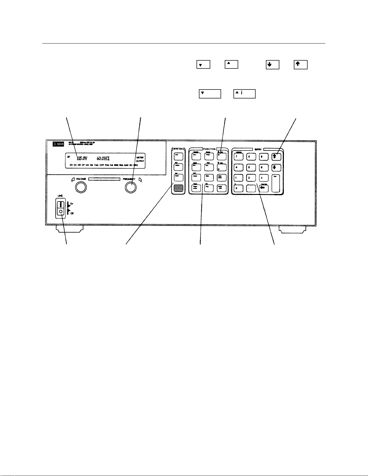
The front panel - at a glance
14-character display
shows menu commands
and measured values.
♦ Annunciators
indicate operating
modes and status
conditions.
Rotary controls set voltage
and frequency when ac
source is in local mode.
♦ Turn rapidly for coarse
control
♦ Turn slowly for fine
control.
ô
and scroll
through menu
commands.
ô index index
and
scroll through lists and
harmonic arrays.
Ë
and
Ì
scroll through
command
parameters.
Turns the ac
source on or off
System keys:
♦ Return to Local mode
♦ Set the GPIB address
and other system
parameters
♦ Set the RS-232
interface
♦ Display SCPI error
codes
♦ Save and recall
instrument states
Function keys:
♦ Enable/disable the
output
♦ Select output phases
♦ Select front panel
metering and harmonic
analysis functions
♦ Program voltage
frequency, phase,
current limit, pulse
parameters, and
waveform shapes
♦ Set and clear protection
functions
♦ Select output and input
coupling
♦ Monitor status
♦ Scroll through front
panel menu commands.
Entry keys:
♦ Enter values
♦ Increment or
decrement values
♦ Scroll through
command
parameters.
♦ Calibrate the ac
source.
3
Page 4

The rear panel - at a glance
Rear Panel Connections (see Chapter 3 in the User’s Guide for details)
1 INH (Remote Inhibit) TTL input signal for externally disabling the power source.
FLT (Discrete Fault Indicator) TTL output signal when there is a device fault.
2 RS-232 connector for remote controller.
3 TRIGGER BNC connectors for external trigger inputs and &source; trigger outputs.
4 GPIB connector and GPIB cable for remote controller.
5 SENSE connections for remote voltage sensing at the load.
6 Airflow Vents (do not block).
7 OUTPUT power connections to the load. (φ2, φ3 connections available on Agilent 6834B only.)
8 AC Input Line Fuses (Agilent 6814B/6834B/6843A only. Other models have internal fuses).
9 LINE RATING label specifies power source required by the power source.
10 AC Line Input connections from the power source.
4
Page 5
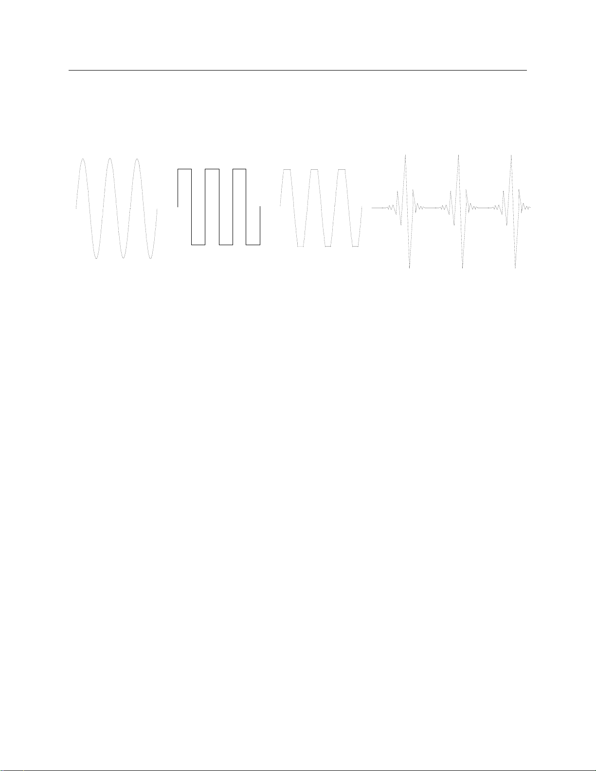
What the ac source can do
Generate waveform shapes
♦ Sinewave ♦ Squarewave ♦ Clipped sinewave ♦ User-definable waveforms
Program the output
Agilent Models 6811B, 6812B, 6813B
♦ Phase
♦ Ac rms voltage ♦ Dc voltage
program the following additional output
functions:
♦ Distortion ♦ Peak Current limit
♦ Frequency ♦ AC coupling
♦ Voltage and frequency slew rates ♦ Impedance
♦ Rms current limit
Make the following measurements
Agilent Models 6811B, 6812B, 6813B
♦ Ac rms, ac + dc rms voltage
♦ Ac rms, ac + dc rms current;
plus repetitive and non-repetitive peak current
♦ Real, reactive, and apparent power ♦ Dc current
♦ Harmonic analysis of voltage and current waveforms
giving amplitude, phase, and total harmonic distortion
results of up to the 50th harmonic.
♦ Triggered acquisition of digitized voltage and current
with extensive post-acquisition calculations
make the following additional
measurements:
♦ Dc voltage
Agilent Model 6834B makes the following
additional measurement:
♦ Total power and neutral current
5
Page 6

Synchronize transient events or measurements with external signals
♦ Triggers applied to the unit ♦ Triggers generated by the unit
Operate in four transient modes
♦ Fixed ♦ Step ♦ Pulse ♦ List
Operate under local or remote control
♦ From the front panel keys
♦ Through the built-in GPIB or RS-232 interfaces
Implement protection features
♦ Over-voltage
♦ Over-current
♦ Over-power
♦ Over-temperature
♦ User-defined external events (via a FLT shutdown signal)
6
Page 7

How to use the front panel
Make sure the unit is turned on.
From the System key group
Local
From the Function key group
Press Local to activate the front panel keypad if the unit is not already in local mode. (If
the Local Lockout command is in effect, cycle power to return the unit to local mode.)
Voltage
Press Voltage to select the voltage function. To select a different function, simply press
the appropriate key.
To select a function appearing above a key (such as Current), first press the blue shift
key, then press the key below the function.
Harmonic
Meter
Output
Input
Status
Protect
Trigger
Trigger
Control
FUNCTION
Current
Voltage
Phase
Freq
Shape
List
Pulse
Index
Index
Phase
Select
Output
on/off
SYSTEM
Local
Error
Address
Save
Recall
Harmonic
Meter
Output
Input
Status
Protect
Trigger
Trigger
Control
FUNCTI
Current
Voltage
Phase
Freq
Shape
List
Pulse
ON
Phase
Select
Output
Index
Index
on/off
NOTE: Pressing Output on/ of f , Phase Sel ect , or (Shift) + Trigger immediately
implements the function. Display annunciators indicate that an immediate action has
occurred. All other function keys have command menus underneath them that are
accessed via the p and q keys after the function key is pressed. Refer to “The front
panel menus- at a glance”.
p
q
Use these keys to move through the command menus of the selected function.
FUNCTION
Harmonic
Meter
Output
Input
Status
Protect
Trigger
Trigger
Control
Current
Voltage
Phase
Freq
Shape
List
Pulse
Phase
Select
Output
Index
Index
on/off
7
Page 8

The following chart shows the commands in the Voltage function menu. Some
commands may not appear on all models. Menus are circular, you can return to the
starting position by continuously pressing p or q.
Key Display Command Function
Voltage
q
q
q
q
q
q
q
q
q
q
q
From the Entry key group
VOLT <value> Set immediate rms output voltage
VOLT:T <value > Set triggered rms output voltage
VOLT:M FIXED Select the voltage mode
OFFSET <value> Set immediate dc offset voltage
OFFSET:T<value> Set triggered dc offset voltage
OFFSET:M FIXED Select the dc offset voltage mode
RANGE 150 Selects the voltage range
SLEW <value> Set immediate voltage slew rate in volts/second
SLEW:T<value> Set triggered voltage slew rate in volts/second
SLEW:M FIXED Select the voltage slew mode
ALC INT Select the voltage sense source
ALC:DET RMS Select the voltage sense detector
°
¯
Use these keys to increment/decrement or select the command parameters to be
executed. If the parameter is a number, use these keys to make minor changes to the
value. Enter enters the selection and returns to the Meter function.
Calibration
789
4
E
0
ENTRY
56
321
-
.
Clear Entry
Enter
Key Display Description
q
Voltage
, ,
1
to
9
Use the numeric Entry keys to directly enter a value for the command parameter. For
example, to enter a value for the voltage parameter:
q
°
°
°
VOLT:M FIXED Sets fixed mode
VOLT:M STEP Sets step mode
VOLT:M PULSE Sets pulse mode
VOLT:M LIST Sets list mode
Key Display Description
Voltage
6
,
Enter
0
VOLT 0 0 volts
VOLT 60 60 volts
60 V 60 Hz enters the value and returns to the Meter
function
8
Page 9

Some basic operations
Make sure the unit is turned on. Use either the front panel keys or the corresponding SCPI commands.
The column on the left indicates the front panel keys that program the indicated action. If the SCPI
programming syntax is substantially different from the front panel menu command, it is shown inside
parentheses ( ).
The text to the right describes the result. If appropriate, the resultant output waveshape is shown
underneath the description.
Enable the output
Output On/Off
When the output is enabled, the programmed voltage appears at the output
and the Dis annunciator turns off.
Select the output phase (Agilent 6834B only)
Phase Select
(INST:NSEL)
You can specify phases individually, or you can couple the phases. When
phases are coupled, all three phase annunciators (φ1, φ2, φ3) on the front
panel are on, indicating that commands will be sent to all three phases.
Note that front panel metering is only done one phase at a time (except for
the total power and neutral current measurements).
Set the voltage
Voltage
1
2
0
VOLT 120
Enter
When this command is sent, the output voltage is set to 120 V rms.
0 V
Set the frequency
120 V rms
Freq
5
0
FREQ 50
Enter
When this command is sent, the output frequency is set to 50 Hz.
60 Hz
50 Hz
120 V rms
9
Page 10

Set the rms current limit (and peak current on Agilent 6811B/6812B/6813B units)
Shift
Current
1
0
CURR:LEV 10
Enter
When this command is sent, the rms current limit is set to 10 A. If more
current than the programmed limit is drawn, the output voltage amplitude is
reduced to keep the rms current within the specified limit. Press Shift
Current and q to access CURR:PEAK, which lets you set the peak
current limit on Agilent 6811B/6812B/6813B units. Note that the peak
current limit circuit on these units acts instantly and clips the output
voltage to maintain the programmed peak limit.
120 V rms
current limit active
NOTE: The rms current limit circuit is slower than the peak current limit circuit and, depending
on the setting of the peak current limit and the load on the output, your unit may generate
momentary peak currents that can well exceed the rms current limit.
Select a waveshape
Shape
°
SHAPE SQUARE
Enter
When this command is sent, the output generates a squarewave. Note that
the peak-to-peak amplitude of the squarewave is less that that of a
sinewave when it is programmed to the same rms voltage amplitude.
Program a protection function
Protect
CURR:LEV 10
Enter
Protect
q
°
CURR:PROT ON
Enter
These commands clear all previously set protection functions and then set
the current protection, which disables the output when an overcurrent
condition is detected. The OCP annunciator will light when this command
is programmed.
120 V rms
0 V
overcurr ent detected
10
Page 11

Measuring the output
All measurements are based on acquiring and subsequently processing output waveform information.
When the ac source is on, it takes measurements and updates the front panel meter continuously. The
Meter key accesses the measurement functions from the front panel.
The SCPI MEASure command acquires new waveform information each time it is executed. The SCPI
FETCh command does not acquire new waveform information but extracts the desired information from
previously acquired waveform data. SCPI commands let you measure phases individually or
simultaneously measure all phases using the FETCh command.
Measurement functions
The following example illustrates the measurements that can be returned by the front panel of the ac
source when sourcing power to a typical non-resistive load such as a power supply. The ac source output
voltage and current waveforms are shown on the next page.
NOTE: On Agilent 6811B, 6812B, and 6813B units, the Input key selects the meter coupling
and hence, what the meter will measure. The choices are: AC only, DC only, or AC +
DC.
Meter
120V 60HZ rms voltage and frequency
(FETC/MEAS)
q
q
q
q
q
q
q
q
q
120V 1.925A rms voltage and current
1.93A 60HZ rms current and frequency
120V 150.5W rms voltage and power
2.82 CREST F current crest factor
5.379A PK REP peak current, repetitive
36.83A PK NR peak current, non repetitive
230.6VA apparent power
175.2 VAR reactive power
0.65 PFACTOR power factor
Note that in addition to the measurement functions listed above, the Agilent 6834B unit can also measure total power
of all phases and neutral rms current.
11
Page 12

Harmonic measurements
Use the harmonic menu to make harmonic measurements of the output current. The following example
illustrates the current magnitude measurements returned at harmonics 0 to 5. Note that harmonic 1 is the
fundamental. Harmonic 0 is the dc component.
Harmonic Shift
0.01A I:MAG:0 current amplitude at harmonic 0
(FETC/MEAS)
pIndex Shift
pIndex Shift
pIndex Shift
pIndex Shift
pIndex Shift
1.43A I:MAG:1 current amplitude at harmonic 1
0.01A I:MAG:2 current amplitude at harmonic 2
0.91A I:MAG:3 current amplitude at harmonic 3
0.01A I:MAG:4 current amplitude at harmonic 4
0.74A I:MAG:5 current amplitude at harmonic 5
Output voltage and current waveforms
RMS Voltage
0
12
Peak Current
(nonrepetitive)
Peak Current
(repetitive)
RM S Curre nt
0
Page 13

Programming output transients
Up to now the ac source has been programmed with the transient system in Fixed mode. The following
examples briefly describe the transient system’s Step, Pulse, and List modes, which require the
application of a trigger to implement the transient mode.
NOTE: For the examples that follow, press Shift Output, scroll to *RST and press Enter to
reset the unit prior to each example. Also press Enter to enter or activate each selection.
Program an output step
Voltage
VOLT:M STEP
VOLT 120
VOLT:T 150
Trigger Control
INIT IMMED
Shift
Trigger
Program an output pulse
Voltage
VOLT:M PULSE
VOLT 120
VOLT:T 90
Pulse
WIDTH .01
PER .03
COUNT 2
Trigger Control
INIT IMMED
Trigger Shift
Step transients transition to a new output level upon receipt of a trigger. When these
commands are sent, the voltage amplitude is stepped from its previous setting to
150 V rms upon receipt of a trigger.
TRIG level
VOLT level
Trigger
Pulse transients transition to a new output level upon receipt of a trigger and return
to the original level after a specified time, repeating this action by the number of
times specified by the count. When these commands are sent, two output pulses step
the voltage amplitude from its previous setting to 90 V rms upon receipt of a
trigger. At the end of the specified period (multiplied by the count), the voltage
returns to its original level.
VOLT level
TRIG level
Width
Trigger
Period
Pulse Count
Program an output list
Voltage
VOLT: M LIST
VOLT 120
List Shift
DWELL [0] .5
DWELL [1] .5
DWELL [2] .5
VOLT [0] 130
VOLT [1] 140
VOLT [2] 150
STEP AUTO
Trigger Control
INIT IMMED
Trigger Shift
List transients generate complex output sequences. When these commands are sent,
the voltage amplitude is sequentially stepped to three levels upon receipt of a
trigger, and then returns to the original voltage level. The output remains at each list
step for .5 seconds. The values inside the brackets ([ ]) are the list index references.
Use Clear Entry to clear a list.
Step 2
Step 1
Step 0
VOLT level
Trigger
List
complete
13
Page 14

More transient examples
The previous examples showed how the transient system can be used to control the output voltage
amplitude. The transient system can also control output frequency, phase, waveform shape, voltage and
frequency slew rates, offset voltage, and peak current limit. The following examples illustrate how the
transient system’s Pulse mode can generate frequency, shape, phase, and voltage slew pulses.
Freq
FREQ:M PULSE
FREQ 60
FREQ:T 50
Pulse
WIDTH .1
Trigger Control
INIT IMMED
Trigger Shift
Shape
SHAPE:M PULSE
SHAPE SINE
SHAPE:T SQUARE
Pulse
WIDTH .05
Trigger Control
INIT IMMED
Trigger Shift
FREQ TRIG
FREQ
width
Trigger
SHAPE TRIG
SHAPE
width
Trigger
Phase Shift
PHASE:M PULSE
PHASE 0
PHASE:T 180
Pulse
WIDTH .05
Trigger Control
INIT IMMED
Trigger Shift
Voltage
VOLT:M PULSE
VOLT 120
VOLT:T 150
SLEW:M PULSE
SLEW 10000
SLEW:T 1000
Pulse
WIDTH .1
Trigger Control
INIT IMMED
Trigger Shift
PHASE TRIG
PHASE
SLEW TRIG
width
Trigger
SLEW
width
Trigger
14
Page 15

Programming trigger synchronization and delays
The previous transient examples were programmed to respond to immediate triggers. However, delayed
and phase synchronized triggers can also be programmed as shown in the following examples.
No delay; no phase synchronization
Voltage
VOLT:M STEP
VOLT 120
VOLT:T 150
Trigger Control
DELAY 0
SYNC:SOUR IMM
INIT:IMMED
Shift Trigger
No delay; 90 degrees phase synchronization
Voltage
VOLT:M STEP
VOLT 120
VOLT:T 150
Trigger Control
DELAY 0
SYNC:SOUR PHAS
SYNC:PHAS 90
INIT:IMMED
Shift
Trigger
When these commands are sent, the voltage amplitude changes immediately
upon the receipt of a trigger.
TRIG level
VOLT level
Trigger
When these commands are sent, the voltage amplitude changes at the next
90 degree phase angle that occurs following the receipt of a trigger.
0
90
TRIG level
VOLT level
Trigger
Trigger delay; no phase synchronization
Voltage
VOLT:M STEP
VOLT 120
VOLT:T 150
Trigger Control
DELAY .0167
SYNC:SOUR IMM
INIT:IMMED
Shift Trigger
When these commands are sent, the voltage amplitude changes .0167
seconds after the receipt of a trigger.
TRIG level
VOLT level
Trigger
Delay
15
Page 16

Trigger delay; 90 degree phase synchronization
Voltage
VOLT:M STEP
VOLT 120
VOLT:T 150
Trigger Control
DELAY .0167
SYNC:SOUR PHAS
SYNC:PHAS 90
INIT:IMMED
Trigger Shift
When these commands are sent, the voltage amplitude changes at the next
90 degree phase angle that occurs after the .0167 second delay has expired,
following the receipt of a trigger.
0
TRIG level
VOLT level
Trigger
90
Delay
More about the trigger system
In the previous examples, a front panel trigger is used to generate the output transients. The trigger is
shown occurring at 270 degrees but actual triggers may occur at any phase. Delay and phase
synchronization however, will occur as programmed.
Note that trigger system used in the ac source provides great flexibility in generating triggers. The
following figure is a simplified model of the trigger system. A complete discussion of the capabilities of
the trigger system is found in the ac source Programming Guide.
IDLE STATE
INIT:IMMED
INITIATED STATE
TRIGGER RECEIVED
DELAYING STATE
DELAY COMPLETED
WAIT FOR SYNC STATE
PHASE ANGLE OCCURS
OUTPUT CHANGES
16
Page 17

The front panel menus - at a glance
<
<
<
<
<
<
<
SYSTEM Keys
Local
Error
Address
ERROR <value> Displays system error codes stored in the SCPI
ADDRESS <value> sets the GPIB address
INTF GPIB | RS232 selects an interface
BAUDRATE 300 | 600 | 1200
2400 | 4800 | 9600
PARITY NONE | EVEN | ODD selects message parity
LANG SCPI | E9012 selects the language
NOUTPUTS 1 | 3 selects t he number of outputs
Save
Recall
Press to save an existing ac source state in nonvolatile memory.
Up to 16 states can be saved (0-15).
Press to place t he ac source into a previously sav ed state.
Up to 16 states can be r ecalled (0-15).
Press to change the ac source’s selected
interface from remot e operation to local (front
panel) operation. Pressing t he key will have no
effect if the interface state is already Local , Localwith-Lockout, or Remote-with-Lockout.
Error Functions
error queue. If no errors exist, a 0 is displayed.
The Err annunciator is lit when there are errors.
Address Functions
selects the baud r ate
1
Save Functions
Recall Functions
First press and release this blue shift key to select
a shifted function. The Shift annunciator lights
when this key is pressed.
FUNCTION Keys
<reading>V <reading>Hz rms voltage and frequency
<reading>V <reading>A rms voltage and rms current
<reading>A <reading>Hz rms current and frequency
<reading>V <reading>W rms voltage and power
<reading> CREST F current crest factor
<reading>A PK REP peak current, repet itive
<reading>A PK NR peak current, nonr epetitive
<reading>VA apparent power
<reading> VAR reactive power
<reading>W TOTAL total power all phases
<reading> PFACTOR power factor
<reading>A NEUTRAL neutral rms curr ent
Output
Input
OUTP:COUP AC | DC select output coupling
*RST executes the *RST c ommand
TTLT:SOUR BOT| EOT| LIST select Trigger Out source coupling
TTLT:STATE ON | OFF set Trigger Out state
IMP:STATE ON | OFF s et output impedance programming
IMP:REAL <value> set real part of output impedance
IMP:REAC <value> set reactive part of output im pedance
PON:STATE RST | RCL0 select power-on state command
RI LATCHING | LIVE | OFF sets remote inhibit mode
DFI ON | OFF sets discrete fault indicator state
DFI:SOUR QUES | OPER
Meter Functions
Output Functions
select the DFI source
1
1
3
3
ESB | RQS | OFF
INP:COUP AC | DC | ACDC choose meter coupling
CURR:RANGE HIGH | LOW current measurement r ange
WINDOW KBESSEL | RECT select harmoni c measurement
Input Functions
3
window meter
3
3
Status
FUNCTION Keys
Harmonic
Meter
Prot
Status Functions
*CLS executes the *CLS command
STATUS:PRESET executes STATus:PRESet command
*ESR? <value> return Event Status register value
reading>A I:MAG: <i ndex> current harmonic magnitude
Harmonic Functions
reading>° I:PHASE: <index>
current harmonic phase
reading>V V:MAG: <index> voltage harmonic magnit ude
reading>° V:PHASE: <index>
voltage harmonic phas e
reading> N:MAG: <index> neutral current harmonic magnitude
reading>° N:PHASE: <index>
neutral current harmonic phase
reading> CURR:THD current total % harmonic distortion
reading> VOLT:THD voltage total % harmonic distortion
Meter functions continued on next column
*STB <value> return Status Byte register value
OPER:EVEN? <value> return STAT:OPER:EVENT? value
OPER:COND <value> return STAT:OPER:COND? value
QUES:EVEN? <value> return STAT:QUES:EVENT? value
QUES:COND <value> return STAT:QUES:COND? value
Protect Functions
PROT:CLEAR cl ears latched protection signal
CURR:PROT ON | OFF set overcurrent protection function
VOLT:PROT ON | OFF set overvoltage protection function
VOLT:PROT <value> set overvoltage protection level
DELAY <value> set a time delay for activating a
protection fault
3
17
Page 18

Trigger
Control
Trigger
Shape
Pressing the Shift Trigger key generates an immediate trigger
Trigger Function
Trigger Control Functi ons
INIT:IMMED Initiate trigger immedi ately
INIT:CONT ON | OFF Initiate trigger continuously
TRIG:SOUR BUS | EXT
Select transient trigger source
TTLT | IMM
DELAY <value> Set trigger delay in seconds
ABORT Abort all trigger sequences
SYNC:SOUR PHASE | IMM Select sync hronous trigger source
SYNC:PHASE <value> Set synchronous phase reference
Current
Voltage
CURR:LEV <value> set immediate rms current limit
Current Functions
CURR:PEAK <value> set immediate peak current limit
CURR:PEAK:T <value> set triggered peak cur rent limit
CURR:PEAK:M FIXED | STEP
select the peak current limit mode
4
3
3
PULSE | LIST
VOLT <value> set immediate ac output voltage
Voltage Functions
VOLT:T<value> set triggered output voltage
VOLT:M FIXED | STEP
select the vol tage mode
4
4
4
PULSE | LIST
RANGE 150 | 300 set the voltage range
OFFSET <value> set immediate dc offset voltage
OFFSET:T<value> set triggered dc offset volt age
OFFSET:M FIXED | STEP
select the dc of fset voltage mode
2, 4
3
3
PULSE | LIST
SLEW <value> set voltage slew in V/sec
4
SLEW:T<value> set triggered voltage slew in V/sec
SLEW:M FIXED | STEP
select the vol tage slew mode
4
PULSE | LIST
OFF:SLW <value> set dc offset sl ew in V/sec
3
OFF:SLW:T<value> set triggered dc offset slew in V/sec
OFF:SLW:M FIXED | STEP
PULSE | LIST
select the dc of fset voltage slew
3
mode
ALC INT | EXT select the voltage sense s ource
ALC:DET RTIME | RMS select the voltage sense detector
Phase
Freq
PHASE <value> set immediate output phase
Phase Functions
PHASE:T <value> set triggered output phase
PHASE:M FIXED | STEP
select the phase mode
4
4
4
PULSE | LIST
FREQ <value> set immediate output f requency
FREQ:T<value> set triggered output frequency
FREQ:M FIXED | STEP
PULSE | LIST
SLEW <value> set frequency slew in Hz/sec
SLEW:T<value> set triggered frequency slew Hz/sec
SLEW:M FIXED | STEP
PULSE | LIST
Freq Functions
select the frequency mode
select the frequency slew mode
SHAPE SINE |SQUARE
set immediate shape
CSIN | <user>
Shape Functions
SHAPE:T SINE |SQUARE
set triggered shape
CSIN | <user>
SHAPE:M FIXED | STEP
set shape mode
PULSE | LIST
CLIP <value> set clipping level
List
Pulse
List Functions
COUNT <value> number of times a list repeats
DWEL:<index> <value> list of output dwell times
FREQ:<index> <val ue> list of output frequencies
FSLW:<index> <val ue> list of output frequency slew rates
IPK:<index> <v alue> list of output peak current limits
3
OFFS:<index> <val ue> list of dc output v oltages
OSLW:<index> <val ue> dc offset voltage slew rate list
PHASE:<index> <val ue> list of output voltage phase
SHAP:<index> SINE | SQUARE
4
angles
list of output waveform shapes
3
3
3
CSIN | <user>
STEP ONCE | AUTO s et response of list to triggers
TTLT:<index> ON | OFF set trigger out pulse list
VOLT:<index> <val ue> list of ac output voltages
VSLW:<index> <value> list of output v oltage slew rates
3
WIDTH <value> set the pulse width
Pulse Functions
4
4
COUNT <value> set the number of output pulses
DCYCLE <value> set the pulse duty cycle
4
PER <value> set the pulse period count
HOLD WIDTH | DCYCLE set parameter that is held constant
3
3
q
ô
Index
p
Index
q p
Index Functions
These are Shift Index keys which are used to scroll t hrough indexed
functions. Press these keys to step through int egers 0 through 50 for a
harmonic list, or 0 through 99 for list points. Hold down these keys to
rapidly access any harmonic or list point.
q p
Functions
These keys let you move through the choices in a command list.
Command lists are c ircular; you can return to the st arting position by
continuously pr essing either key.
Phase
Select
This key applies to 3-phase ac sources only.
Pressing this key successively selects phase 1
first, followed by phase 2, phase 3, and then all
three phases.
Output
On/Off
This key toggles the output on and off. When off,
the ac source output is disabled and the Dis
annunciator is on.
18
Page 19

ENTRY Keys
¯ °
These keys let you scroll through choices in a par ameter list that
apply to a specif ic command. Parameter lists are ci rcular; you can
return to the starting position by continuously pr essing either key. If
the command has a numeric r ange, these keys increment or
decrement the exis ting value.
90
−
−
.
Enter
E
0
The numeric keys 0 through 9 are used for
entering numeric values.
Press shift and this key to ent er a minus.
Press this key alone to enter a decimal point.
Until you press the Enter key, the values or
parameters you enter with the other Entry
keys are displayed but not entered into the
ac source.
Press Shift and this key to enter an exponent.
Clear Entry
Calibration
7
Notes:
1 Valid for Model Agilent 6834B only
2 Valid for Models Agil ent 6814B, 6834B, and 6843A only
3 Valid for Models Agil ent 6811B, 6812B, and 6813B only
4 Phase selectable on Agi lent 6834B
Press Shift and this key to abort a keypad
entry and clear the value. When editing a
list, pressing Clear Entry truncates or clears
the list at the presently displayed list point.
Press this key alone to backspace and delete
the last digit entered
Press Shift and thi s key to access the
calibration menu. Refer to appendix B In the
user’s for more information.
19
Page 20

Agilent Sales and Support Offices
For more information about Agilent Technologies test and measurement products, applications, services,
and for a current sales office listing, visit our web site: http://www.agilent.com/find/tmdir
You can also contact one of the following centers and ask for a test and measurement sales
representative.
United States:
Agilent Technologies
Test and Measurement Call Center
P.O. Box 4026
Englewood, CO 80155-4026
(tel) 1 800 452 4844
Canada:
Agilent Technologies Canada Inc.
5150 Spectrum Way
Mississauga, Ontario
L4W 5G1
(tel) 1 877 894 4414
Europe:
Agilent Technologies
Test & Measurement European Marketing Organisation
P.O. Box 999
1180 AZ Amstelveen
The Netherlands
(tel) (31 20) 547 9999
Latin America:
Agilent Technologies
Latin American Region Headquarters
5200 Blue Lagoon Drive, Suite #950
Miami, Florida 33126
U.S.A.
(tel) (305) 267 4245
(fax) (305) 267 4286
Australia/New Zealand:
Agilent Technologies Australia Pty Ltd
347 Burwood Highway
Forest Hill, Victoria 3131
(tel) 1-800 629 485 (Australia)
(fax) (61 3) 9272 0749
(tel) 0 800 738 378 (New Zealand)
(fax) (64 4) 802 6881
Asia Pacific:
Agilent Technologies
24/F, Cityplaza One, 1111 King’s Road,
Taikoo Shing, Hong Kong
tel: (852)-3197-7777
fax: (852)-2506-9284
Japan:
Agilent Technologies Japan Ltd.
Measurement Assistance Center
9-1, Takakura-Cho, Hachioji-Shi,
Tokyo 192-8510, Japan
(tel) (81) 426 56 7832
(fax) (81) 426 56 7840
Technical data is subject to change.
20
 Loading...